US7835431B2 - Systems and methods for loop length and bridged tap length determination of a transmission line - Google Patents
Systems and methods for loop length and bridged tap length determination of a transmission lineDownload PDFInfo
- Publication number
- US7835431B2 US7835431B2US12/694,128US69412810AUS7835431B2US 7835431 B2US7835431 B2US 7835431B2US 69412810 AUS69412810 AUS 69412810AUS 7835431 B2US7835431 B2US 7835431B2
- Authority
- US
- United States
- Prior art keywords
- channel transfer
- transfer function
- loop
- estimated
- length
- Prior art date
- Legal status (The legal status is an assumption and is not a legal conclusion. Google has not performed a legal analysis and makes no representation as to the accuracy of the status listed.)
- Expired - Fee Related
Links
Images


Classifications
- H—ELECTRICITY
- H04—ELECTRIC COMMUNICATION TECHNIQUE
- H04B—TRANSMISSION
- H04B3/00—Line transmission systems
- H04B3/02—Details
- H04B3/46—Monitoring; Testing
- H04B3/493—Testing echo effects or singing
- H—ELECTRICITY
- H04—ELECTRIC COMMUNICATION TECHNIQUE
- H04B—TRANSMISSION
- H04B3/00—Line transmission systems
- H04B3/02—Details
- H04B3/46—Monitoring; Testing
- H—ELECTRICITY
- H04—ELECTRIC COMMUNICATION TECHNIQUE
- H04L—TRANSMISSION OF DIGITAL INFORMATION, e.g. TELEGRAPHIC COMMUNICATION
- H04L1/00—Arrangements for detecting or preventing errors in the information received
- H04L1/004—Arrangements for detecting or preventing errors in the information received by using forward error control
- H—ELECTRICITY
- H04—ELECTRIC COMMUNICATION TECHNIQUE
- H04L—TRANSMISSION OF DIGITAL INFORMATION, e.g. TELEGRAPHIC COMMUNICATION
- H04L1/00—Arrangements for detecting or preventing errors in the information received
- H04L1/24—Testing correct operation
- H—ELECTRICITY
- H04—ELECTRIC COMMUNICATION TECHNIQUE
- H04L—TRANSMISSION OF DIGITAL INFORMATION, e.g. TELEGRAPHIC COMMUNICATION
- H04L1/00—Arrangements for detecting or preventing errors in the information received
- H04L1/24—Testing correct operation
- H04L1/245—Testing correct operation by using the properties of transmission codes
- H—ELECTRICITY
- H04—ELECTRIC COMMUNICATION TECHNIQUE
- H04L—TRANSMISSION OF DIGITAL INFORMATION, e.g. TELEGRAPHIC COMMUNICATION
- H04L25/00—Baseband systems
- H04L25/02—Details ; arrangements for supplying electrical power along data transmission lines
- H04L25/0202—Channel estimation
- H04L25/0212—Channel estimation of impulse response
- H04L25/0216—Channel estimation of impulse response with estimation of channel length
- H—ELECTRICITY
- H04—ELECTRIC COMMUNICATION TECHNIQUE
- H04L—TRANSMISSION OF DIGITAL INFORMATION, e.g. TELEGRAPHIC COMMUNICATION
- H04L43/00—Arrangements for monitoring or testing data switching networks
- H04L43/50—Testing arrangements
- H—ELECTRICITY
- H04—ELECTRIC COMMUNICATION TECHNIQUE
- H04L—TRANSMISSION OF DIGITAL INFORMATION, e.g. TELEGRAPHIC COMMUNICATION
- H04L5/00—Arrangements affording multiple use of the transmission path
- H04L5/14—Two-way operation using the same type of signal, i.e. duplex
- H04L5/1438—Negotiation of transmission parameters prior to communication
- H—ELECTRICITY
- H04—ELECTRIC COMMUNICATION TECHNIQUE
- H04M—TELEPHONIC COMMUNICATION
- H04M3/00—Automatic or semi-automatic exchanges
- H04M3/08—Indicating faults in circuits or apparatus
- H04M3/085—Fault locating arrangements
- H—ELECTRICITY
- H04—ELECTRIC COMMUNICATION TECHNIQUE
- H04M—TELEPHONIC COMMUNICATION
- H04M3/00—Automatic or semi-automatic exchanges
- H04M3/22—Arrangements for supervision, monitoring or testing
- H04M3/2227—Quality of service monitoring
- H—ELECTRICITY
- H04—ELECTRIC COMMUNICATION TECHNIQUE
- H04M—TELEPHONIC COMMUNICATION
- H04M3/00—Automatic or semi-automatic exchanges
- H04M3/22—Arrangements for supervision, monitoring or testing
- H04M3/26—Arrangements for supervision, monitoring or testing with means for applying test signals or for measuring
- H04M3/28—Automatic routine testing ; Fault testing; Installation testing; Test methods, test equipment or test arrangements therefor
- H04M3/30—Automatic routine testing ; Fault testing; Installation testing; Test methods, test equipment or test arrangements therefor for subscriber's lines, for the local loop
- H04M3/305—Automatic routine testing ; Fault testing; Installation testing; Test methods, test equipment or test arrangements therefor for subscriber's lines, for the local loop testing of physical copper line parameters, e.g. capacitance or resistance
- H04M3/306—Automatic routine testing ; Fault testing; Installation testing; Test methods, test equipment or test arrangements therefor for subscriber's lines, for the local loop testing of physical copper line parameters, e.g. capacitance or resistance for frequencies above the voice frequency, e.g. xDSL line qualification
- H—ELECTRICITY
- H04—ELECTRIC COMMUNICATION TECHNIQUE
- H04L—TRANSMISSION OF DIGITAL INFORMATION, e.g. TELEGRAPHIC COMMUNICATION
- H04L25/00—Baseband systems
- H04L25/02—Details ; arrangements for supplying electrical power along data transmission lines
- H04L25/0202—Channel estimation
- H—ELECTRICITY
- H04—ELECTRIC COMMUNICATION TECHNIQUE
- H04M—TELEPHONIC COMMUNICATION
- H04M3/00—Automatic or semi-automatic exchanges
- H04M3/22—Arrangements for supervision, monitoring or testing
- H04M3/2209—Arrangements for supervision, monitoring or testing for lines also used for data transmission
Definitions
- This inventionrelates to determination of transmission line characteristics.
- this inventionrelates to systems and methods for determining loop lengths and bridged tap lengths of a transmission line.
- the collection and exchange of diagnostic and test information between transceivers in a telecommunications environmentis an important part of a telecommunications, such as an ADSL, deployment.
- a telecommunicationssuch as an ADSL
- communications over a local subscriber loop between a central office and a subscriber premisesis accomplished by modulating the data to be transmitted onto a multiplicity of discrete frequency carriers which are summed together and then transmitted over the subscriber loop.
- the carriersform discrete, non-overlapping communication subchannels of limited bandwidth.
- the carriersform what is effectively a broadband communications channel.
- the carriersare demodulated and the data recovered.
- DSL systemsexperience disturbances from other data services on adjacent phone lines, such as, for example, ADSL, HDSL, ISDN, T1, or the like. These disturbances may commence after the subject ADSL service is already initiated and, since DSL for internet access is envisioned as an always-on service, the effect of these disturbances must be ameliorated by the subject ADSL transceiver.
- Identifying, measuring and characterizing the condition of a transmission lineis a key element of an ADSL deployment.
- the transceiver connectionis not performing as expected, for example, the data rate is low, there are many bit errors, a data link is not possible, or the like, it is important to be able to identify the loop length and the existence, location and length of any bridged taps without having to send a technician to the remote modem site to run diagnostic tests.
- This inventiondescribes a system and method for estimating the loop length, the number of bridged taps and length of the bridged taps on a transmission line from readily available modem data.
- the loop length, the number of bridge taps and the length of the bridged tapscan be estimated by comparing a measured frequency domain channel impulse response of the transmission line to a model of a transmission line that is composed of multiple sections and multiple bridge taps.
- the diagnostic and test information describing the condition of the linecan then be exchanged, for example, by two transceivers during a diagnostic link mode, such as that described in U.S. patent application Ser. No. 09/755,173 filed Jan. 8, 2001, entitled “Systems And Methods For Establishing A Diagnostic Transmission Mode And Communicating Over The Same,” now U.S. Pat. No. 6,658,052, which is incorporated herein by reference in its entirety.
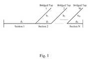
- FIG. 1illustrates an exemplary multiple section loop with multiple bridged taps
- FIG. 2illustrates a graph of the measured received reverb signal and the theoretical model for downstream data
- FIG. 3illustrates a graph of the measured received reverb signal and the theoretical model for upstream data
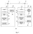
- FIG. 4is a functional block diagram illustrating an exemplary loop length and bridged tap length estimation system according to this invention.
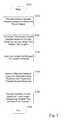
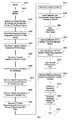
- FIG. 5is a flowchart outlining an exemplary general method for determining loop length and bridged tap lengths according to this invention
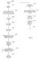
- FIG. 6is a flowchart outlining an exemplary method for estimating the loop length and bridged tap length in the upstream direction according to this invention.
- FIG. 7is a flowchart outlining an exemplary method for estimating the loop length and bridged tap length in the downstream direction according to this invention.
- the frequency domain channel impulse response of the subscriber loopis measured at a set of discrete frequency values.
- FIG. 1illustrates an exemplary model of a loop with N sections and M bridged taps.
- an estimate of the optimal parameter vector x that best approximates the measured channel impulse response H m (f i )can be determined given the model H(x,f).
- the frequency domain model H(x,f)can also incorporate the effect of, for example, an imperfectly matched transmission line, by including the effects of the load and source impedances.
- the loop characterization algorithmsemploy a model based approach to estimate the length of the loop and the lengths of up to two bridged taps.
- a channel characterization algorithmcompares the measured channel impulse response to the channel impulse response of a loop model consisting of a single-gauge wire and containing up to two bridged taps.
- the loop length and the bridged tap lengthsare the parameters of the theoretical channel impulse response. The system varies the parameters of the theoretical model and evaluates the difference between the measured channel impulse response and the theoretical channel impulse response. The loop length/bridged tap lengths that minimize the error function are then declared as the estimated values.
- the presence of a bridged tapis declared if the bridged tap length is greater than a predetermined length, such as one hundred feet.
- a predetermined lengthsuch as one hundred feet.
- This threshold for bridged tap detectionwas set experimentally. It was determined that for most loops there is a chance that a phantom bridged tap with a small length will be detected because of modeling inaccuracies and noise in the measurement system. Since the lengths of these phantom bridged taps were almost always below 100 ft, the exemplary threshold was set to 100 ft. However, in general the threshold can be altered depending on the particular operational environment and the complexity of the model.
- fis a dummy variable denoting frequency
- the downstream reverb signalis collected at the customer-premises equipment (CPE) and upstream reverb signal is collected at central office (CO). While there is no difference in the data collection process for the upstream or the downstream reverb signal, the characteristics of these two data sets are quite different. Specifically, the downstream reverb data contains significantly more information. Furthermore, there are more samples of the frequency domain reverb signal available in the downstream direction and these samples cover an extended range in the frequency domain where the effects of bridged taps on impulse response can be easily detected. However, there is one crucial difference between the upstream and the downstream data sets which complicates using the same interpretation algorithm for both. In the downstream channel, the matching of the front-end impedance to the loop impedance tends to be better than in the upstream channel. This makes it possible to use a simplified channel model for the downstream channel. Unfortunately, the impedance matching in the upstream channel is generally not as good as in the downstream channel and a more complicated channel impulse response should be used.
- the basic upstream channel characterization algorithmis limited in terms of estimation accuracy and the number of bridged taps that can be detected.
- the channel modelby extending the channel model to include multiple sections of varying gauges and/or more than two bridged taps, the presence of more than two bridged taps can be detected and more accurate results for the lengths of individual sections of the loop determined if there is a change of wire gauge along the loop.
- the only trade offis that as the number of model parameters increase, the computational effort needed to estimate the parameters will increase as well.
- an exemplary two-wire loopis characterized by its characteristic impedance:
- FIG. 2An example of the operation of the algorithm for an exemplary loop is illustrated in FIG. 2 .
- Displayedare the measured received reverb signal Rx(f) and the theoretical model H (d, b 1 ,b 2 ,f) which were obtained by finding the model parameters d,b 1 ,b 2 that best match the data.
- the observed (dashed line) received reverb signal Rx(f)is plotted against the theoretical channel model (solid line) H(d,b 1 ,b 2 ,f) as functions of frequency for an exemplary 6000 ft loop with an exemplary single 1300 ft bridged tap.
- the exemplary loopconsisted of a 26 awg. 6000 ft wire with a 26 awg. 1300 ft bridged tap close to the CPE.
- the global minimum of E(d,b 1 ,b 2 )is desired.
- the parameters (d p ,b 1 q ,b 2 r ) which result in the minimum cost among the sampled valuesare chosen. This requires evaluating the cost function at P ⁇ Q ⁇ R locations.
- the frequency dependent propagation constant ⁇ (f) for a number of wires of different gaugesneeds to be stored.
- 24 awg. and 26 awg. wiresare used which require 4 ⁇ N locations to store the real and the imaginary parts of ⁇ (f) for N ADSL tones.
- the analog front end (AFE) compensation curvesneed be stored which occupy N locations in memory.
- the loop transfer functioncan be determined directly from Eq.
- the algorithmfor example, if the algorithm were implemented on a personal computer or workstation, or it may be necessary to store the log [2+tan h(b 1 ⁇ )] terms in regular intervals as required by the sampling procedure for (d p ,b 1 q ,b 2 r ).
- the channel transfer functionis again measured by averaging K frames of the received reverb signal as given by Eq. 1.
- the theoretical model for the channel transfer function in the upstream casecan be described in two steps.
- the first stepconsists of writing the equations for the current and the voltage at the source (CPE), I s , V s , in terms of current and voltage at the load (CO), I L , V L , through the application of ABCD matrices:
- a i , B, F s and F Lare 2 ⁇ 2 matrices whose elements are arrays of N elements.
- a iis a matrix representing the frequency domain response of the ith section of the loop
- Bis the matrix representing the response of the bridged tap
- F S and F Lare the matrices representing the frequency domain response of the analog front end (AFE) hardware of the modem circuitry for TX (source) and RX (load) paths.
- AFEanalog front end
- FIG. 3An example of the operation of the upstream loop length and bridged tap length estimation algorithm is illustrated in FIG. 3 .
- the measured received reverb signal Rx(f) and the theoretical model H(d,b 1 ,b 2 ,f), which was obtained by finding the model parameters d,b 1 b 2 that best match the data,are displayed.
- the exemplary loopconsisted of 26 awg. 7700 ft wire with a 26 awg. 600 ft bridged tap 5900 ft away from CO.
- FIG. 3illustrates the observed (dashed line) received reverb signal Rx(f) plotted against the theoretical channel model (solid line) H (d 1 , d 2 , J) as functions of frequency for an exemplary 7700 ft loop with a single 600 ft bridged tap.
- FIG. 4illustrates an exemplary loop length and bridged tap length estimation system according to an embodiment of this invention for downstream data.
- the loop length and bridged tap length estimation system 100comprises a downstream loop length and bridged tap length determination device 200 , an upstream loop length and bridged tap length determination device 300 , a central office modem 20 and a consumer-premises modem 30 , connected by link 10 , such as a twisted pair.
- the a downstream loop length and bridged tap length determination device 200comprises a controller 210 , an I/O interface 220 , a storage device 230 , a reverb signal determination device 240 , a loop length output device 250 and a bridged tap output device 260 , connected by link 5 .
- the upstream loop length and bridged tap length determination device 300comprises a controller 310 , an I/O interface 320 , a storage device 330 , a reverb signal determination device 340 , an impedance determination device 350 , a modem identification device 360 , a loop length output device 370 and a bridged tap output device 380 , connected by link 5 .
- the various components of the loop length and the bridged tap length estimation system 100can be located at distant portions of a distributed network, such as a local area network, a wide area network, an intranet and/or the Internet, or within a dedicated loop length and bridged tap length estimation system.
- a distributed networksuch as a local area network, a wide area network, an intranet and/or the Internet
- the components of the loop length and bridged tap length estimation system 100can be combined into one device or collocated on a particular node of a distributed network.
- the components of the loop length and the bridged tap length estimation system 100can be arranged at any location, such as in a general purpose computer or within a distributed network without affecting the operation of the system.
- the links 5can be a wired or a wireless link or any other known or later developed element(s) that is capable of supplying electronic data to and from the connected elements.
- the controller 210in cooperation with the I/O interface 220 triggers initialization of the modem 20 .
- the reverb signal determination device 240in cooperation with the modem 20 , the controller 210 and the I/O interface 220 determines a transfer function by averaging K consecutive frames of a reverb signal.
- the loop length, a first bridged tap length and a second bridged tap lengthare input from an input device (not shown) such as a computer, a laptop, a terminal, a transmission line testing device, or the like, or retrieved from the storage device 230 .
- the controller 210in cooperation with the storage device 230 , then determines the frequency domain propagation function for a specified wire gauge, and the frequency domain loop model.
- the calibrated and compensated reverb signals in the frequency domainare stored in the storage device 230 and the reference wire gauge input or retrieved from the storage device 230 .
- the controller 210in cooperation with the storage device 230 determines the number of elements in the Rx function and the difference between the actual and the measured transfer function.
- the loop length output devicein cooperation with the I/O interface then outputs the estimated loop length to, for example, a computer, a laptop, a terminal, a transmission line testing device, or the like.
- the bridged tap output deviceoutputs the estimated bridged tap length to, for example, a computer, a laptop, a terminal, a transmission line testing device, or the like.
- the controller 310in cooperation with the I/O interface 320 triggers initialization of the modem 30 .
- the reverb signal determination device 340in cooperation with the modem 30 , the controller 310 and the I/O interface 320 determines a transfer function by averaging K consecutive frames of a reverb signal.
- the controller 310in cooperation with the storage device 230 , determines the frequency domain propagation function for a specified wire gauge, where the specified wire gauge is input or retrieved from the storage device 330 .
- the controller 310in cooperation with the storage device 330 and the impedance determination device 350 , determines the frequency domain impedance of the specified wire gauge. Then, the controller 310 , in cooperation with the storage device 330 and the impedance determination device 350 , determines the transmit impedance of the CPE modem and the receive impedance of the CO modem.
- the controller 310in cooperation with the storage device 330 , determines the matrix representing the frequency domain responses of the i th section of the loop, the matrix representing the response of the bridged tap, and the F S matrix representing the AFE circuitry for the source (TX) and load (RX) paths and stores them in the storage device 330 , and estimates the transfer function H.
- the calibrated and the compensated reverb signal in the frequency domain and the reference gauge of the wireare input or retrieved from the storage device 330 .
- the modem identification determining device 360determines the identification of the CO modem collecting the upstream reverb signal, and the identification of the CPE modem transmitting the upstream reverb signal. Knowing the number of elements in the Rx function, the controller 310 minimizes the difference between the actual and measured transfer functions, and outputs, with the cooperation of the loop length output device 370 and the bridged tap output device 380 , the estimated loop length and the estimated bridged tap length, respectively.
- FIG. 5illustrates an exemplary method of determining a loop length and bridged tap lengths.
- controlbegins in step S 100 and continues to step S 110 .
- step S 110the channel impulse response is estimated based on a measured reverb signal.
- step S 120the theoretical channel impulse response of a loop model is determined using a loop length and the bridged tap lengths.
- step S 130the loop length and the bridged tap lengths of the model are varied. Control then continues to step S 140 .
- step S 140the difference between the measured channel impulse response and the theoretical channel impulse is monitored.
- step S 150the estimated values of the loop length and bridged tap length are declared based on the loop lengths and bridged tap lengths that minimize the error function between the measured channel impulse response and the theoretical channel impulse response. Control then continues to step S 160 where the control sequence ends.
- FIG. 6illustrates an exemplary method of determining the loop length and the bridged tap length for downstream data.
- controlbegins in step S 200 and continues to step S 210 .
- step S 210a modem is initialized.
- step S 220a transfer function is determined by averaging K consecutive frames of the reverb signal.
- step S 230the loop length is input. Control then continues to step S 240 .
- step S 240a first bridged tap length is input.
- step S 250a second bridged tap length is input.
- step S 260the frequency domain propagation function is determined for a specified wire gauge. Control then continues to step S 270 .
- step S 270the frequency domain loop model is determined.
- step S 280the calibrated and compensated reverb signals in the frequency domain are input.
- step S 290the reference wire gauge is input. Control then continues to step S 300 .
- step S 300the number of elements in the Rx function are input.
- step S 310the difference between the actual and the measured transfer function are determined.
- step S 320the estimated loop length is determined Control then continues to step S 330 .
- step S 330the estimated bridged tap length is determined Control then continues to step S 340 where the control sequence ends.
- FIG. 7illustrates an exemplary method of determining the loop length and bridged tap length for upstream data.
- controlbegins in step S 500 and continues to step S 510 .
- step S 510the modem is initialized.
- step S 520the transfer function is determined by averaging K consecutive frames of the reverb signal.
- step S 530the frequency domain propagation function for the wire gauge in use is determined. Control then continues to step S 540 .
- step S 540the frequency domain impedance of the wire gauge is determined.
- step S 550the transmit impedance of the CPE modem is determined.
- step S 560the receive impedance of the CO modem is determined Control then continues to step S 570 .
- step S 570the matrix representing the frequency domain responses of the i th section of the loop are determined.
- step S 580the matrix representing the response of the bridged tap is determined.
- step S 590the F S matrix representing the AFE circuitry for the source (TX) and load (RX) paths are determined Control then continues to step S 600 .
- step S 600the transfer function H is estimated.
- step S 610the calibrated and the compensated reverb signal in the frequency domain are input.
- step S 620the reference gauge of the wire is input. Control then continues to step S 630 .
- step S 630the identification of the CO modem collecting the upstream reverb signal is input.
- step S 640the identification of the CPE modem transmitting the upstream reverb is input.
- step S 650the number of elements in the Rx function are input. Control then continues to step S 660 .
- step S 660the difference between the actual and measured transfer functions are minimized.
- step S 670the estimated loop length is determined.
- step S 680the estimated bridged tap length is determined Control then continues to step S 690 where the control sequence ends.
- the loop length and bridged tap length estimation systemcan be implemented either on a single program general purpose computer, or a separate program general purpose computer.
- the loop length and bridged tap length estimation systemcan also be implemented on a special purpose computer, a programmed microprocessor or microcontroller and peripheral integrated circuit element, an ASIC or other integrated circuit, a digital signal processor, a hard wired electronic or logic circuit such as a discrete element circuit, a programmable logic device such as a PLD, PLA, FPGA, PAL, a modem, or the like.
- any device capable of implementing a finite state machinethat is in turn capable of implementing the flowcharts illustrated in FIG. 5-7 can be used to implement the loop length and bridged tap length estimation system according to this invention.
- the disclosed methodmay be readily implemented in software using object or object-oriented software development environments that provide portable source code that can be used on a variety of computer or workstation hardware platforms.
- the disclosed loop length and bridged tap length estimation systemmay be implemented partially or fully in hardware using standard logic circuits or VLSI design. Whether software or hardware is used to implement the systems in accordance with this invention is dependent on the speed and/or efficiency requirements of the system, the particular function, and the particular software or hardware systems or microprocessor or microcomputer systems being utilized.
- loop length and bridged tap length estimation systems and methods illustrated hereincan be readily implemented in hardware and/or software using any known or later-developed systems or structures, devices and/or software by those of ordinary skill in the applicable art from the functional description provided herein and a general basic knowledge of the computer arts.
- the disclosed methodsmay be readily implemented as software executed on a programmed general purpose computer, a special purpose computer, a microprocessor, or the like.
- the methods and systems of this inventioncan be implemented as a program embedded on a personal computer such as a Java® or CGI script, as a resource residing on a server or graphics workstation, as a routine embedded in a dedicated loop length and bridged tap length estimation system, a modem, a dedicated loop length and/or bridged tap length estimation system, or the like.
- the loop length and bridged tap length estimation systemcan also be implemented by physically incorporating the system and method into a software and/or hardware system, such as the hardware and software systems of a dedicated loop length and bridged tap length estimation system or modem.
Landscapes
- Engineering & Computer Science (AREA)
- Signal Processing (AREA)
- Computer Networks & Wireless Communication (AREA)
- Quality & Reliability (AREA)
- Power Engineering (AREA)
- Cable Transmission Systems, Equalization Of Radio And Reduction Of Echo (AREA)
- Telephonic Communication Services (AREA)
- Monitoring And Testing Of Transmission In General (AREA)
- Telephone Function (AREA)
- Analysing Materials By The Use Of Radiation (AREA)
Abstract
Description
x=[d1, d2.. . . , dN, b1, b2.. . . , bM,].
Assuming that the number of sections of the multiple section subscriber loop, N, and the number of bridged taps, M, are known, an estimate of the optimal parameter vector x that best approximates the measured channel impulse response Hm(fi) can be determined given the model H(x,f). The optimal parameter vector set x* can be estimated by minimizing the norm of the difference between the measured and the model frequency response, at the discrete frequency values fi=iΔf, for i=0, 1, . . . , k−1. This minimization can be performed using the expression:
If the number of the bridged taps on the loop is not known, by adopting a large number of bridged taps in the model frequency response, and assuming that the minimization will converge to a solution with the correct number of bridged taps with non-zero length, the remaining bridge taps will have length zero.
where f is a dummy variable denoting frequency and rx(n), for n=1, . . . , N, are the samples of the time-domain received reverb signal within a frame, with N being the number of samples contained in a single frame.
fi=iΔf, i=1, . . . N/2. (2)
The reverb signal is transmitted over a portion of the entire ADSL spectrum. For example, the reverb signal is available at 224 (96 in G.Lite) tones from f32=32Δf to f255=255Δf in the downstream channel and at 26 tones from f6=6Δf to f31=31Δf in the upstream channel. The downstream reverb signal is collected at the customer-premises equipment (CPE) and upstream reverb signal is collected at central office (CO). While there is no difference in the data collection process for the upstream or the downstream reverb signal, the characteristics of these two data sets are quite different. Specifically, the downstream reverb data contains significantly more information. Furthermore, there are more samples of the frequency domain reverb signal available in the downstream direction and these samples cover an extended range in the frequency domain where the effects of bridged taps on impulse response can be easily detected. However, there is one crucial difference between the upstream and the downstream data sets which complicates using the same interpretation algorithm for both. In the downstream channel, the matching of the front-end impedance to the loop impedance tends to be better than in the upstream channel. This makes it possible to use a simplified channel model for the downstream channel. Unfortunately, the impedance matching in the upstream channel is generally not as good as in the downstream channel and a more complicated channel impulse response should be used.
And its propagation constant:
γ(f)=√{square root over ((R+jωL)(G+jωC))}{square root over ((R+jωL)(G+jωC))}
where ω=2πf is the radian frequency and R (resistance), L (inductance), G (admittance) and C (capacitance) are the frequency dependent constants of the loop and vary with wire gauge. For a perfectly terminated loop, or a very long loop, with length d, and two bridged taps of lengths b1and b2, the transfer function of the loop H(d, b1, b2, f), is given by:
log|H(d,b1,b2,f)|=log(2)−dγ(f)−log [2+tanh(b1γ)]−log [2+tanh(b2γ)]. (4)
where Rx(fi) is the received reverb signal sampled at fI=iΔf and iiare iiare the first and the last tones Rx(fi).
Since the cost function E(d,b1,b2) is a nonlinear of d, b1and b2, the function contains many local minima. Therefore, many well known optimization algorithms such as Gauss-Newton should not be used since these algorithms are unable to cope with multiple local minima and they converge to a local minimum of the cost function. In this exemplary embodiment the global minimum of E(d,b1,b2) is desired. For this reason, a brute-force global minimization algorithm is used where the cost function is sampled at the points (dp,b1q,b2r), dp=pΔD, b1q=qΔb1and b2r=rΔb2with p=1, . . . , P, q=1, . . . , Q and r=1, . . . , R. Next the parameters (dp,b1q,b2r) which result in the minimum cost among the sampled values are chosen. This requires evaluating the cost function at P×Q×R locations.
where Ai, B, Fsand FLare 2×2 matrices whose elements are arrays of N elements. Here, Aiis a matrix representing the frequency domain response of the ith section of the loop, B is the matrix representing the response of the bridged tap and FSand FLare the matrices representing the frequency domain response of the analog front end (AFE) hardware of the modem circuitry for TX (source) and RX (load) paths. From Eq. 7 the transfer function of the channel can be derived and is given by:
where d1is the length of the section before a bridged tap and d2is the length of the section after the bridged tap. Note that the CO interpretation algorithm uses a two-section, single bridged tap model. This is because of the limited number of frequency bins, fi=iΔf, from tone i=6 to i=32, at which the transfer function is available.
A11i=A22i=cosh(γdi)
A12i=Z0sinh(γdi),A21i=A21iZ0−2
Entries of matrix B:
B11=B22=1
B12=0, B21=Zj−1(b)
Where Zj−1=tan h(bγ)/Z0, and finally:
F11S=F22S=1, F12S=0, F21S=ZS
F11L=F22L=1, F12L=0, F21L=ZL−1
The estimation algorithm minimizes the difference between the measured and the actual transfer functions:
Claims (14)
Priority Applications (7)
| Application Number | Priority Date | Filing Date | Title |
|---|---|---|---|
| US12/694,128US7835431B2 (en) | 2000-01-07 | 2010-01-26 | Systems and methods for loop length and bridged tap length determination of a transmission line |
| US12/902,677US8094703B2 (en) | 2000-01-07 | 2010-10-12 | Systems and methods for loop length and bridged tap length determination of a transmission line |
| US13/307,228US8369394B2 (en) | 2000-01-07 | 2011-11-30 | Systems and methods for loop length and bridged tap length determination of a transmission line |
| US13/750,277US8553750B2 (en) | 2000-01-07 | 2013-01-25 | Systems and methods for loop length and bridged tap length determination of a transmission line |
| US14/046,723US8687680B2 (en) | 2000-01-07 | 2013-10-04 | Systems and methods for loop length and bridged tap length determination of a transmission line |
| US14/227,827US8958466B2 (en) | 2000-01-07 | 2014-03-27 | Systems and methods for loop length and bridged tap length determination of a transmission line |
| US14/598,026US9191066B2 (en) | 2000-01-07 | 2015-01-15 | Systems and methods for loop length and bridged tap length determination of a transmission line |
Applications Claiming Priority (5)
| Application Number | Priority Date | Filing Date | Title |
|---|---|---|---|
| US17486600P | 2000-01-07 | 2000-01-07 | |
| US22430800P | 2000-08-10 | 2000-08-10 | |
| US09/755,172US6865221B2 (en) | 2000-01-07 | 2001-01-08 | Systems and methods for loop length and bridged tap length determination of a transmission line |
| US11/033,310US7852910B2 (en) | 2000-01-07 | 2005-01-12 | Systems and methods for loop length and bridged tap length determination of a transmission line |
| US12/694,128US7835431B2 (en) | 2000-01-07 | 2010-01-26 | Systems and methods for loop length and bridged tap length determination of a transmission line |
Related Parent Applications (1)
| Application Number | Title | Priority Date | Filing Date |
|---|---|---|---|
| US11/033,310ContinuationUS7852910B2 (en) | 2000-01-07 | 2005-01-12 | Systems and methods for loop length and bridged tap length determination of a transmission line |
Related Child Applications (2)
| Application Number | Title | Priority Date | Filing Date |
|---|---|---|---|
| US12/902,677ContinuationUS8094703B2 (en) | 2000-01-07 | 2010-10-12 | Systems and methods for loop length and bridged tap length determination of a transmission line |
| US12/902,677Continuation-In-PartUS8094703B2 (en) | 2000-01-07 | 2010-10-12 | Systems and methods for loop length and bridged tap length determination of a transmission line |
Publications (2)
| Publication Number | Publication Date |
|---|---|
| US20100142602A1 US20100142602A1 (en) | 2010-06-10 |
| US7835431B2true US7835431B2 (en) | 2010-11-16 |
Family
ID=26870618
Family Applications (9)
| Application Number | Title | Priority Date | Filing Date |
|---|---|---|---|
| US09/755,172Expired - LifetimeUS6865221B2 (en) | 2000-01-07 | 2001-01-08 | Systems and methods for loop length and bridged tap length determination of a transmission line |
| US11/033,310Expired - Fee RelatedUS7852910B2 (en) | 2000-01-07 | 2005-01-12 | Systems and methods for loop length and bridged tap length determination of a transmission line |
| US12/694,128Expired - Fee RelatedUS7835431B2 (en) | 2000-01-07 | 2010-01-26 | Systems and methods for loop length and bridged tap length determination of a transmission line |
| US12/902,677Expired - Fee RelatedUS8094703B2 (en) | 2000-01-07 | 2010-10-12 | Systems and methods for loop length and bridged tap length determination of a transmission line |
| US13/307,228Expired - Fee RelatedUS8369394B2 (en) | 2000-01-07 | 2011-11-30 | Systems and methods for loop length and bridged tap length determination of a transmission line |
| US13/750,277Expired - Fee RelatedUS8553750B2 (en) | 2000-01-07 | 2013-01-25 | Systems and methods for loop length and bridged tap length determination of a transmission line |
| US14/046,723Expired - Fee RelatedUS8687680B2 (en) | 2000-01-07 | 2013-10-04 | Systems and methods for loop length and bridged tap length determination of a transmission line |
| US14/227,827Expired - Fee RelatedUS8958466B2 (en) | 2000-01-07 | 2014-03-27 | Systems and methods for loop length and bridged tap length determination of a transmission line |
| US14/598,026Expired - Fee RelatedUS9191066B2 (en) | 2000-01-07 | 2015-01-15 | Systems and methods for loop length and bridged tap length determination of a transmission line |
Family Applications Before (2)
| Application Number | Title | Priority Date | Filing Date |
|---|---|---|---|
| US09/755,172Expired - LifetimeUS6865221B2 (en) | 2000-01-07 | 2001-01-08 | Systems and methods for loop length and bridged tap length determination of a transmission line |
| US11/033,310Expired - Fee RelatedUS7852910B2 (en) | 2000-01-07 | 2005-01-12 | Systems and methods for loop length and bridged tap length determination of a transmission line |
Family Applications After (6)
| Application Number | Title | Priority Date | Filing Date |
|---|---|---|---|
| US12/902,677Expired - Fee RelatedUS8094703B2 (en) | 2000-01-07 | 2010-10-12 | Systems and methods for loop length and bridged tap length determination of a transmission line |
| US13/307,228Expired - Fee RelatedUS8369394B2 (en) | 2000-01-07 | 2011-11-30 | Systems and methods for loop length and bridged tap length determination of a transmission line |
| US13/750,277Expired - Fee RelatedUS8553750B2 (en) | 2000-01-07 | 2013-01-25 | Systems and methods for loop length and bridged tap length determination of a transmission line |
| US14/046,723Expired - Fee RelatedUS8687680B2 (en) | 2000-01-07 | 2013-10-04 | Systems and methods for loop length and bridged tap length determination of a transmission line |
| US14/227,827Expired - Fee RelatedUS8958466B2 (en) | 2000-01-07 | 2014-03-27 | Systems and methods for loop length and bridged tap length determination of a transmission line |
| US14/598,026Expired - Fee RelatedUS9191066B2 (en) | 2000-01-07 | 2015-01-15 | Systems and methods for loop length and bridged tap length determination of a transmission line |
Country Status (10)
| Country | Link |
|---|---|
| US (9) | US6865221B2 (en) |
| EP (1) | EP1245085B1 (en) |
| JP (3) | JP4311902B2 (en) |
| KR (1) | KR100683289B1 (en) |
| AT (1) | ATE332593T1 (en) |
| AU (1) | AU2632601A (en) |
| CA (2) | CA2394826C (en) |
| DE (1) | DE60121290T2 (en) |
| ES (2) | ES2265411T3 (en) |
| WO (1) | WO2001052439A1 (en) |
Cited By (3)
| Publication number | Priority date | Publication date | Assignee | Title |
|---|---|---|---|---|
| US20110026569A1 (en)* | 2000-01-07 | 2011-02-03 | Aware, Inc. | Systems and methods for loop length and bridged tap length determination of a transmission line |
| US10887450B1 (en)* | 2018-09-06 | 2021-01-05 | Adtran, Inc. | Systems and methods for locating faults in a telecommunication line using line test data |
| US20220069863A1 (en)* | 2020-08-26 | 2022-03-03 | PassiveLogic Inc. | Perceptible Indicators Of Wires Being Attached Correctly To Controller |
Families Citing this family (40)
| Publication number | Priority date | Publication date | Assignee | Title |
|---|---|---|---|---|
| EP2267914A3 (en) | 2000-01-07 | 2012-09-26 | Aware, Inc. | Systems and methods for loop length and bridged tap length determination of a transmission line |
| US6782043B1 (en)* | 2000-01-18 | 2004-08-24 | Lsi Logic Corporation | Method and apparatus for estimating the length of a transmission line |
| KR100697002B1 (en)* | 2001-02-17 | 2007-03-20 | 삼성전자주식회사 | Initialization Method for High Speed Digital Subscriber Line with Tone Spacing Control and Supporting System |
| ES2270967T3 (en)* | 2001-04-02 | 2007-04-16 | Alcatel | METHOD AND APPLIANCE FOR THE IDENTIFICATION OF AN ACCESS NETWORK THROUGH 1-PORT MEASUREMENTS. |
| WO2002087103A1 (en)* | 2001-04-19 | 2002-10-31 | Aware, Inc. | Single-ended measurement method and system using abcd-matrix theory of transmission lines |
| EP1382188A2 (en)* | 2001-04-26 | 2004-01-21 | Aware, Inc. | Systems and methods for loop characterization from double-ended measurements |
| CA2358379A1 (en)* | 2001-10-05 | 2003-04-05 | Elysium Broadband Inc. | Method and device for preventing signal loss in unterminated bridge taps |
| US6782082B2 (en) | 2002-02-15 | 2004-08-24 | Broadcom Corporation | Method and system for reducing cross-talk and avoiding bridged taps |
| US7015948B2 (en)* | 2002-04-05 | 2006-03-21 | Spx Corporation | Method and apparatus for real time testing of DTV antenna transmitting systems in time domain under full power |
| DE10226348A1 (en)* | 2002-06-13 | 2004-01-15 | Infineon Technologies Ag | Method and circuit arrangement for the detection of pupin coils |
| ATE426964T1 (en)* | 2003-02-04 | 2009-04-15 | Tracespan Comm Ltd | INFLUENCE-FREE MODEM PERFORMANCE ANALYSIS |
| JP4500309B2 (en)* | 2003-05-02 | 2010-07-14 | イカノス・コミュニケーションズ・インコーポレイテッド | Automatic mode selection in Annex C |
| JP4348138B2 (en)* | 2003-08-01 | 2009-10-21 | パナソニック株式会社 | ADSL modem device |
| US7446622B2 (en)* | 2003-09-05 | 2008-11-04 | Infinera Corporation | Transmission line with low dispersive properties and its application in equalization |
| US7302379B2 (en)* | 2003-12-07 | 2007-11-27 | Adaptive Spectrum And Signal Alignment, Inc. | DSL system estimation and parameter recommendation |
| US7809116B2 (en)* | 2003-12-07 | 2010-10-05 | Adaptive Spectrum And Signal Alignment, Inc. | DSL system estimation including known DSL line scanning and bad splice detection capability |
| WO2005069856A2 (en)* | 2004-01-14 | 2005-08-04 | Conexant Systems, Inc. | Method and apparatus for single end loop testing for dsl provisioning and maintenance |
| US7388906B2 (en)* | 2004-05-03 | 2008-06-17 | Sbc Knowledge Ventures, L.P. | Method for detecting bridged taps on telephony cable |
| US7440497B2 (en)* | 2004-11-01 | 2008-10-21 | Lsi Corporation | Serial data link using decision feedback equalization |
| US7623630B2 (en)* | 2005-04-08 | 2009-11-24 | Ikanos Communications, Inc. | Double-ended line probing (DELP) for DSL systems |
| US7405405B2 (en)* | 2005-05-17 | 2008-07-29 | General Electric Company | Method and system for reconstructing an image in a positron emission tomography (PET) system |
| CN1870611A (en)* | 2005-05-26 | 2006-11-29 | 华为技术有限公司 | Method and system for estimating channel property parameter |
| AU2006268292B2 (en) | 2005-07-10 | 2011-03-24 | Adaptive Spectrum And Signal Alignment, Incorporated | DSL system estimation |
| DE102006015055B4 (en)* | 2006-03-31 | 2007-12-27 | Nokia Siemens Networks Gmbh & Co.Kg | Method, arrangement and device for transmitting information between a central and at least one decentralized unit in a communication network |
| US20080292064A1 (en)* | 2007-05-21 | 2008-11-27 | Xidong Wu | Methods and apparatus to characterize a digital subscriber line (dsl) subscriber loop |
| US20080310617A1 (en)* | 2007-06-14 | 2008-12-18 | Infineon Technologies Ag | Transmission Links |
| CN101159777B (en)* | 2007-11-09 | 2011-02-09 | 华为技术有限公司 | Line measuring method and measuring device |
| TW200934154A (en)* | 2007-12-28 | 2009-08-01 | Panasonic Corp | Communication device and communication system |
| CN101572569B (en)* | 2008-05-04 | 2013-01-23 | 华为技术有限公司 | Line topological management method, system and correlative device |
| US8170088B2 (en)* | 2008-11-19 | 2012-05-01 | Harris Corporation | Methods for determining a reference signal at any location along a transmission media |
| US20100124263A1 (en)* | 2008-11-19 | 2010-05-20 | Harris Corporation | Systems for determining a reference signal at any location along a transmission media |
| US20100123618A1 (en)* | 2008-11-19 | 2010-05-20 | Harris Corporation | Closed loop phase control between distant points |
| US8249176B2 (en)* | 2008-11-20 | 2012-08-21 | At&T Intellectual Property I, Lp | Method for determination of bridged taps on a transmission line |
| US20110062472A1 (en)* | 2009-09-17 | 2011-03-17 | Koninklijke Philips Electronics N.V. | Wavelength-converted semiconductor light emitting device |
| EP2675074B1 (en)* | 2012-06-13 | 2014-08-06 | Alcatel Lucent | Method and device for detecting a bridged tap within a telecommunication line |
| EP2712160B1 (en)* | 2012-09-24 | 2014-06-18 | Alcatel Lucent | Method and device for testing subscriber premises equipment |
| US9185204B2 (en) | 2013-07-29 | 2015-11-10 | Ikanos Communications, Inc. | Method and apparatus for designing an improved transmit signal for use in a single ended line test (SELT) |
| EP3739764B1 (en)* | 2019-05-17 | 2024-07-31 | Nokia Solutions and Networks Oy | Method and apparatus for determining a bridged tap length |
| CN112013506B (en)* | 2019-05-31 | 2022-02-25 | 青岛海尔空调电子有限公司 | Method and device for communication detection, air conditioner |
| TWI773966B (en)* | 2020-02-20 | 2022-08-11 | 瑞昱半導體股份有限公司 | Operation method and receiver device |
Citations (43)
| Publication number | Priority date | Publication date | Assignee | Title |
|---|---|---|---|---|
| US4571733A (en) | 1981-12-28 | 1986-02-18 | Fujitsu Limited | Automatic equalization device and method of starting-up the same |
| US4630228A (en) | 1982-06-28 | 1986-12-16 | Systron-Donner Corporation | Transmission line analyzer for automatically identifying the severities and locations of multiple mismatches |
| US5068614A (en) | 1990-11-05 | 1991-11-26 | Tektronix, Inc. | Swept frequency domain relectometry enhancement |
| US5128619A (en) | 1989-04-03 | 1992-07-07 | Bjork Roger A | System and method of determining cable characteristics |
| JPH05288794A (en) | 1992-04-14 | 1993-11-02 | Nec Corp | Bridge tap transmission line position specifying system in subscriber's line |
| WO1997001900A1 (en) | 1995-06-26 | 1997-01-16 | Ericsson Austria Ag | Method of bi-directional data transmission over a two-wire line |
| GB2303032A (en) | 1995-06-30 | 1997-02-05 | Samsung Electronics Co Ltd | Adaptive bit swapping between channels of a discrete multitone system |
| US5864602A (en) | 1997-04-28 | 1999-01-26 | Nynex Science & Technologies, Inc. | Qualifying telephone line for digital transmission service |
| WO1999026375A2 (en) | 1997-11-14 | 1999-05-27 | Tektronix, Inc. | Method of operating a digital data distribution network |
| US5994905A (en) | 1997-12-02 | 1999-11-30 | Wavetek Corporation | Frequency domain reflectometer and method of suppressing harmonics |
| US6002671A (en) | 1997-09-03 | 1999-12-14 | Fluke Corporation | Test instrument for testing asymmetric digital subscriber lines |
| US6058162A (en) | 1997-12-05 | 2000-05-02 | Harris Corporation | Testing of digital subscriber loops using multi-tone power ratio (MTPR) waveform |
| US6091713A (en)* | 1998-04-13 | 2000-07-18 | Telcordia Technologies, Inc. | Method and system for estimating the ability of a subscriber loop to support broadband services |
| EP1041731A1 (en) | 1999-03-31 | 2000-10-04 | Alcatel | Method and arrangement to estimate transmission channel characteristics |
| WO2000064130A2 (en) | 1999-04-20 | 2000-10-26 | Teradyne, Inc. | Determining the physical structure of subscriber lines |
| WO2001001158A1 (en) | 1999-06-25 | 2001-01-04 | Telcordia Technologies, Inc. | Single ended measurement method and system for determining subscriber loop make up |
| US6177801B1 (en) | 1999-04-21 | 2001-01-23 | Sunrise Telecom, Inc. | Detection of bridge tap using frequency domain analysis |
| US6205202B1 (en) | 1998-03-23 | 2001-03-20 | Yokogawa Electric Corporation | Subscriber line tester |
| US6215855B1 (en) | 1999-01-21 | 2001-04-10 | Bell Atlantic Network Services, Inc. | Loop certification and measurement for ADSL |
| WO2001052439A1 (en) | 2000-01-07 | 2001-07-19 | Aware, Inc. | Systems and methods for loop length and bridged tap length determination of a transmission line |
| US6292539B1 (en) | 1998-05-29 | 2001-09-18 | Verizon Laboratories Inc. | Method and apparatus for digital subscriber loop qualification |
| US6292468B1 (en) | 1998-12-31 | 2001-09-18 | Qwest Communications International Inc. | Method for qualifying a loop for DSL service |
| US20010043568A1 (en) | 1996-03-29 | 2001-11-22 | Mchale John F. | Communication server apparatus and method |
| WO2002013405A2 (en) | 2000-08-10 | 2002-02-14 | Aware, Inc. | Systems and methods for characterizing transmission lines in a multi-carrier dsl environment |
| US6370187B1 (en) | 1998-04-01 | 2002-04-09 | Texas Instruments Incorporated | Adaptive power dissipation for data communications system |
| US20020041657A1 (en) | 1999-11-12 | 2002-04-11 | A. John Ulanskas | Method for controlling dsl transmission power |
| US20020131537A1 (en)* | 2001-01-25 | 2002-09-19 | Andrew Storm | Approach for processing data received from a communications channel to reduce noise power and optimize impulse response length to reduce inter-symbol interference and inter-channel interference |
| US6487276B1 (en) | 1999-09-30 | 2002-11-26 | Teradyne, Inc. | Detecting faults in subscriber telephone lines |
| US6512597B1 (en) | 1999-11-17 | 2003-01-28 | Lexmark International, Inc. | Method and apparatus for correcting unadjusted threshold arrays for halftoning by use of parameterized transfer functions that generate adjusted threshold arrays at run time |
| US6512789B1 (en) | 1999-04-30 | 2003-01-28 | Pctel, Inc. | Partial equalization for digital communication systems |
| US6516049B1 (en) | 2000-06-06 | 2003-02-04 | Ikanos Communications, Inc. | Method and apparatus for insertion loss estimation in wireline communications |
| US6538451B1 (en) | 1999-06-25 | 2003-03-25 | Telcordia Technologies, Inc. | Single ended measurement method and system for determining subscriber loop make up |
| US6553098B1 (en) | 2000-04-11 | 2003-04-22 | Verizon Laboratories Inc. | Apparatus and method for assessing leakage from cable networks |
| US6584176B2 (en) | 1999-05-25 | 2003-06-24 | Adtran Inc. | Loop loss measurement and reporting mechanism for digital data services telephone channel equipment |
| US20030156685A1 (en) | 2001-06-08 | 2003-08-21 | Erving Richard Henry | Method and system for testing subscriber loops using touchtone telephone signals |
| US20030198217A1 (en) | 2002-04-01 | 2003-10-23 | Redfern Arthur J. | Spectrally compatible mask for enhanced upstream data rates in DSL systems |
| US6650697B1 (en) | 1998-09-18 | 2003-11-18 | Nortel Networks Limited | Wireline communication system and method of frequency allocation therein |
| US6658052B2 (en) | 2000-01-07 | 2003-12-02 | Aware, Inc. | Systems and methods for establishing a diagnostic transmission mode and communicating over the same |
| US20030231023A1 (en) | 2001-11-07 | 2003-12-18 | Aware, Inc. | Modeling and calibrating a three-port time-domain reflectometry system |
| US20040076119A1 (en) | 2002-06-25 | 2004-04-22 | Aronson Lewis B. | Transceiver module and integrated circuit with dual eye openers and integrated loopback and bit error rate testing |
| US6751254B1 (en)* | 1999-05-05 | 2004-06-15 | Panasonic Communications Co., Ltd. | Activation of multiple xDSL modems with power control measurement |
| US6829330B2 (en) | 2001-04-26 | 2004-12-07 | Aware, Inc. | Systems and methods for loop characterization from double-ended measurements |
| US6965578B1 (en) | 1998-09-30 | 2005-11-15 | Conexant Systems, Inc. | Echo canceling method and apparatus for digital data communication system |
Family Cites Families (4)
| Publication number | Priority date | Publication date | Assignee | Title |
|---|---|---|---|---|
| US653098A (en)* | 1900-04-13 | 1900-07-03 | John Edward Laidlaw | Non-reclosable bottle. |
| US5991311A (en)* | 1997-10-25 | 1999-11-23 | Centillium Technology | Time-multiplexed transmission on digital-subscriber lines synchronized to existing TCM-ISDN for reduced cross-talk |
| US6259746B1 (en)* | 1998-01-14 | 2001-07-10 | Motorola Inc. | Method for allocating data and power in a discrete multi-tone communication system |
| US6782082B2 (en)* | 2002-02-15 | 2004-08-24 | Broadcom Corporation | Method and system for reducing cross-talk and avoiding bridged taps |
- 2001
- 2001-01-08ESES01900917Tpatent/ES2265411T3/ennot_activeExpired - Lifetime
- 2001-01-08DEDE2001621290patent/DE60121290T2/ennot_activeExpired - Lifetime
- 2001-01-08WOPCT/US2001/000420patent/WO2001052439A1/enactiveIP Right Grant
- 2001-01-08ESES06013787Tpatent/ES2407155T3/ennot_activeExpired - Lifetime
- 2001-01-08CACA2394826Apatent/CA2394826C/ennot_activeExpired - Fee Related
- 2001-01-08AUAU26326/01Apatent/AU2632601A/ennot_activeAbandoned
- 2001-01-08KRKR1020027008792Apatent/KR100683289B1/ennot_activeExpired - Fee Related
- 2001-01-08CACA2687472Apatent/CA2687472C/ennot_activeExpired - Fee Related
- 2001-01-08EPEP20010900917patent/EP1245085B1/ennot_activeExpired - Lifetime
- 2001-01-08USUS09/755,172patent/US6865221B2/ennot_activeExpired - Lifetime
- 2001-01-08ATAT01900917Tpatent/ATE332593T1/ennot_activeIP Right Cessation
- 2001-01-08JPJP2001552546Apatent/JP4311902B2/ennot_activeExpired - Fee Related
- 2005
- 2005-01-12USUS11/033,310patent/US7852910B2/ennot_activeExpired - Fee Related
- 2008
- 2008-07-24JPJP2008191009Apatent/JP4473327B2/ennot_activeExpired - Fee Related
- 2010
- 2010-01-04JPJP2010000204Apatent/JP2010148120A/enactivePending
- 2010-01-26USUS12/694,128patent/US7835431B2/ennot_activeExpired - Fee Related
- 2010-10-12USUS12/902,677patent/US8094703B2/ennot_activeExpired - Fee Related
- 2011
- 2011-11-30USUS13/307,228patent/US8369394B2/ennot_activeExpired - Fee Related
- 2013
- 2013-01-25USUS13/750,277patent/US8553750B2/ennot_activeExpired - Fee Related
- 2013-10-04USUS14/046,723patent/US8687680B2/ennot_activeExpired - Fee Related
- 2014
- 2014-03-27USUS14/227,827patent/US8958466B2/ennot_activeExpired - Fee Related
- 2015
- 2015-01-15USUS14/598,026patent/US9191066B2/ennot_activeExpired - Fee Related
Patent Citations (49)
| Publication number | Priority date | Publication date | Assignee | Title |
|---|---|---|---|---|
| US4571733A (en) | 1981-12-28 | 1986-02-18 | Fujitsu Limited | Automatic equalization device and method of starting-up the same |
| US4630228A (en) | 1982-06-28 | 1986-12-16 | Systron-Donner Corporation | Transmission line analyzer for automatically identifying the severities and locations of multiple mismatches |
| US5128619A (en) | 1989-04-03 | 1992-07-07 | Bjork Roger A | System and method of determining cable characteristics |
| US5068614A (en) | 1990-11-05 | 1991-11-26 | Tektronix, Inc. | Swept frequency domain relectometry enhancement |
| JPH05288794A (en) | 1992-04-14 | 1993-11-02 | Nec Corp | Bridge tap transmission line position specifying system in subscriber's line |
| WO1997001900A1 (en) | 1995-06-26 | 1997-01-16 | Ericsson Austria Ag | Method of bi-directional data transmission over a two-wire line |
| GB2303032A (en) | 1995-06-30 | 1997-02-05 | Samsung Electronics Co Ltd | Adaptive bit swapping between channels of a discrete multitone system |
| US20010043568A1 (en) | 1996-03-29 | 2001-11-22 | Mchale John F. | Communication server apparatus and method |
| US5864602A (en) | 1997-04-28 | 1999-01-26 | Nynex Science & Technologies, Inc. | Qualifying telephone line for digital transmission service |
| US6002671A (en) | 1997-09-03 | 1999-12-14 | Fluke Corporation | Test instrument for testing asymmetric digital subscriber lines |
| WO1999026375A2 (en) | 1997-11-14 | 1999-05-27 | Tektronix, Inc. | Method of operating a digital data distribution network |
| US5994905A (en) | 1997-12-02 | 1999-11-30 | Wavetek Corporation | Frequency domain reflectometer and method of suppressing harmonics |
| US6058162A (en) | 1997-12-05 | 2000-05-02 | Harris Corporation | Testing of digital subscriber loops using multi-tone power ratio (MTPR) waveform |
| US6205202B1 (en) | 1998-03-23 | 2001-03-20 | Yokogawa Electric Corporation | Subscriber line tester |
| US6370187B1 (en) | 1998-04-01 | 2002-04-09 | Texas Instruments Incorporated | Adaptive power dissipation for data communications system |
| US6091713A (en)* | 1998-04-13 | 2000-07-18 | Telcordia Technologies, Inc. | Method and system for estimating the ability of a subscriber loop to support broadband services |
| US6292539B1 (en) | 1998-05-29 | 2001-09-18 | Verizon Laboratories Inc. | Method and apparatus for digital subscriber loop qualification |
| US6650697B1 (en) | 1998-09-18 | 2003-11-18 | Nortel Networks Limited | Wireline communication system and method of frequency allocation therein |
| US6965578B1 (en) | 1998-09-30 | 2005-11-15 | Conexant Systems, Inc. | Echo canceling method and apparatus for digital data communication system |
| US6292468B1 (en) | 1998-12-31 | 2001-09-18 | Qwest Communications International Inc. | Method for qualifying a loop for DSL service |
| US6215855B1 (en) | 1999-01-21 | 2001-04-10 | Bell Atlantic Network Services, Inc. | Loop certification and measurement for ADSL |
| JP2000332662A (en) | 1999-03-31 | 2000-11-30 | Alcatel | Method and apparatus for evaluating transmission channel characteristics |
| US6606719B1 (en) | 1999-03-31 | 2003-08-12 | Alcatel | Method and arrangement to estimate transmission channel characteristics |
| EP1041731A1 (en) | 1999-03-31 | 2000-10-04 | Alcatel | Method and arrangement to estimate transmission channel characteristics |
| WO2000064130A2 (en) | 1999-04-20 | 2000-10-26 | Teradyne, Inc. | Determining the physical structure of subscriber lines |
| US20020090060A1 (en) | 1999-04-20 | 2002-07-11 | Ilia L. Rudinsky | Determining the physical structure of subscriber lines |
| US6177801B1 (en) | 1999-04-21 | 2001-01-23 | Sunrise Telecom, Inc. | Detection of bridge tap using frequency domain analysis |
| US6512789B1 (en) | 1999-04-30 | 2003-01-28 | Pctel, Inc. | Partial equalization for digital communication systems |
| US6751254B1 (en)* | 1999-05-05 | 2004-06-15 | Panasonic Communications Co., Ltd. | Activation of multiple xDSL modems with power control measurement |
| US6584176B2 (en) | 1999-05-25 | 2003-06-24 | Adtran Inc. | Loop loss measurement and reporting mechanism for digital data services telephone channel equipment |
| US6538451B1 (en) | 1999-06-25 | 2003-03-25 | Telcordia Technologies, Inc. | Single ended measurement method and system for determining subscriber loop make up |
| WO2001001158A1 (en) | 1999-06-25 | 2001-01-04 | Telcordia Technologies, Inc. | Single ended measurement method and system for determining subscriber loop make up |
| US6487276B1 (en) | 1999-09-30 | 2002-11-26 | Teradyne, Inc. | Detecting faults in subscriber telephone lines |
| US20020041657A1 (en) | 1999-11-12 | 2002-04-11 | A. John Ulanskas | Method for controlling dsl transmission power |
| US6512597B1 (en) | 1999-11-17 | 2003-01-28 | Lexmark International, Inc. | Method and apparatus for correcting unadjusted threshold arrays for halftoning by use of parameterized transfer functions that generate adjusted threshold arrays at run time |
| US6658052B2 (en) | 2000-01-07 | 2003-12-02 | Aware, Inc. | Systems and methods for establishing a diagnostic transmission mode and communicating over the same |
| WO2001052439A1 (en) | 2000-01-07 | 2001-07-19 | Aware, Inc. | Systems and methods for loop length and bridged tap length determination of a transmission line |
| US6865221B2 (en) | 2000-01-07 | 2005-03-08 | Aware, Inc. | Systems and methods for loop length and bridged tap length determination of a transmission line |
| US20050123030A1 (en) | 2000-01-07 | 2005-06-09 | Aware, Inc. | Systems and methods for loop length and bridged tap length determination of a transmission line |
| US6553098B1 (en) | 2000-04-11 | 2003-04-22 | Verizon Laboratories Inc. | Apparatus and method for assessing leakage from cable networks |
| US6516049B1 (en) | 2000-06-06 | 2003-02-04 | Ikanos Communications, Inc. | Method and apparatus for insertion loss estimation in wireline communications |
| WO2002013405A2 (en) | 2000-08-10 | 2002-02-14 | Aware, Inc. | Systems and methods for characterizing transmission lines in a multi-carrier dsl environment |
| US20020114383A1 (en) | 2000-08-10 | 2002-08-22 | Murat Belge | Systems and methods for characterizing transmission lines using broadband signals in a multi-carrier DSL environment |
| US20020131537A1 (en)* | 2001-01-25 | 2002-09-19 | Andrew Storm | Approach for processing data received from a communications channel to reduce noise power and optimize impulse response length to reduce inter-symbol interference and inter-channel interference |
| US6829330B2 (en) | 2001-04-26 | 2004-12-07 | Aware, Inc. | Systems and methods for loop characterization from double-ended measurements |
| US20030156685A1 (en) | 2001-06-08 | 2003-08-21 | Erving Richard Henry | Method and system for testing subscriber loops using touchtone telephone signals |
| US20030231023A1 (en) | 2001-11-07 | 2003-12-18 | Aware, Inc. | Modeling and calibrating a three-port time-domain reflectometry system |
| US20030198217A1 (en) | 2002-04-01 | 2003-10-23 | Redfern Arthur J. | Spectrally compatible mask for enhanced upstream data rates in DSL systems |
| US20040076119A1 (en) | 2002-06-25 | 2004-04-22 | Aronson Lewis B. | Transceiver module and integrated circuit with dual eye openers and integrated loopback and bit error rate testing |
Non-Patent Citations (34)
| Title |
|---|
| Cioffi John M., ADSL Maintenance with DMT, T1E1.4 ADSL Project, Amati Communications Corporation, Dec. 1, 1992, pp. 1-14. |
| Decision of Refusal (including translation) for Japanese Patent Application No. 2008-191009, Dispatched Sep. 7, 2009. |
| Decision to Grant European Patent for European Patent Application No. 01900917.4, dated Jun. 9, 2006. |
| Decision to Grant Patent (including translation) for Korean Patent Application No. 10-2002-7008792, dated Nov. 20, 2006. |
| European Search Report for European Patent Application No. 06013787, completed Nov. 7, 2006. |
| Examination Report for European Patent Application No. 01900917.4, dated Jan. 21, 2003. |
| Examination Report for European Patent Application No. 01900917.4, dated May 4, 2004. |
| Examination Report for European Patent Application No. 06013787, dated Aug. 17, 2007. |
| Examiner's First Report on Australian Patent Application No. 26326/01, mailed Feb. 18, 2004. |
| International Preliminary Examination Report for International (PCT) Patent Application No. PCT/US01/00420, mailed Apr. 29, 2002. |
| International Search Report for PCT/US01/00420 dated May 28, 2001; 4 pages. |
| Lewis L. et al.: "Extending Trouble Ticket Systems To Fault Diagnostics" IEEE Network, Nov. 1993, pp. 44-51, XP 000575228. |
| Marcos Tzannes "Draft New Recommendation G.996.1: Test Procedures For Digital Subscriber Line (DSL) Transceivers -For Approval", Mar. 1999, 2 pages. |
| Notice of Acceptance for Australian Patent Application No. 2005211639, mailed Oct. 12, 2006. |
| Notice of Allowability for U.S. Appl. No. 11/033,310, mailed Sep. 8, 2010. |
| Notice of Allowance for Canadian Patent Application No. 2,394,826, mailed Jun. 10, 2009. |
| Notice of Allowance for Japanese Patent Application No. 2008-191009, mailed Mar. 1, 2010. |
| Notification of Reason for Refusal (including translation) for Japanese Patent Application No. 2008-191009, Dispatched Apr. 27, 2009. |
| Notification of Reason for Refusal (including translation) for Japanese Patent Application No. 2010-000204, mailed Jun. 28, 2010. |
| Notification of Reason for Refusal for Japanese Patent Application No. 2001-552546, Dispatched Sep. 16, 2008. |
| Official Action for Canadian Patent Application No. 2,394,826, mailed Jun. 23, 2008. |
| Official Action for U.S. Appl. No. 11/033,310, mailed Apr. 21, 2010. |
| Official Action for U.S. Appl. No. 11/033,310, mailed Aug. 17, 2010. |
| Official Action for U.S. Appl. No. 11/033,310, mailed Jan. 23, 2008. |
| Official Action for U.S. Appl. No. 11/033,310, mailed Jun. 1, 2009. |
| Official Action for U.S. Appl. No. 11/033,310, mailed Nov. 17, 2008. |
| Official Action for U.S. Appl. No. 11/033,310, mailed Nov. 17, 2009. |
| Patrick Boets et al.: "The Modelling Aspect Of Transmission Line Networks" Proceedings Of The Instrumentation And Measurement Technology Conference, US, New York, IEEE, May 12, 1992, pp. 137-141, XP 000343913. |
| Ranier Storn et al. "Differential Evolution-A Simple And Efficient Adaptive Scheme For Global Optimization Over Continuous Spaces", Mar. 1995, 12 pages. |
| Ranier Storn et al. "Differential Evolution—A Simple And Efficient Adaptive Scheme For Global Optimization Over Continuous Spaces", Mar. 1995, 12 pages. |
| Rizzi, P. A., Microwave Engineering, Appendix C "Transmission Matrices", Prentice-Hall, Englewood Cliffs, N.J., 1988, pp. 534-540. |
| Storn, R. and Price, K., Differential Evolution-A Simple and Efficient Heuristic for Global Optimization over Continuous Spaces, Journal of Global Optimization 11, Kluwer Academic Publishers, 1997, pp. 341-359. |
| Storn, R. and Price, K., Differential Evolution—A Simple and Efficient Heuristic for Global Optimization over Continuous Spaces, Journal of Global Optimization 11, Kluwer Academic Publishers, 1997, pp. 341-359. |
| Written Opinion for International (PCT) Patent Application No. PCT/US01/00420, mailed Feb. 20, 2002. |
Cited By (22)
| Publication number | Priority date | Publication date | Assignee | Title |
|---|---|---|---|---|
| US20110026569A1 (en)* | 2000-01-07 | 2011-02-03 | Aware, Inc. | Systems and methods for loop length and bridged tap length determination of a transmission line |
| US8094703B2 (en) | 2000-01-07 | 2012-01-10 | Aware, Inc. | Systems and methods for loop length and bridged tap length determination of a transmission line |
| US8369394B2 (en) | 2000-01-07 | 2013-02-05 | Aware, Inc. | Systems and methods for loop length and bridged tap length determination of a transmission line |
| US8553750B2 (en) | 2000-01-07 | 2013-10-08 | Aware, Inc. | Systems and methods for loop length and bridged tap length determination of a transmission line |
| US8687680B2 (en) | 2000-01-07 | 2014-04-01 | Aware, Inc. | Systems and methods for loop length and bridged tap length determination of a transmission line |
| US8958466B2 (en) | 2000-01-07 | 2015-02-17 | Broadcom Corporation | Systems and methods for loop length and bridged tap length determination of a transmission line |
| US9191066B2 (en) | 2000-01-07 | 2015-11-17 | Broadcom Corporation | Systems and methods for loop length and bridged tap length determination of a transmission line |
| US10887450B1 (en)* | 2018-09-06 | 2021-01-05 | Adtran, Inc. | Systems and methods for locating faults in a telecommunication line using line test data |
| US20220069863A1 (en)* | 2020-08-26 | 2022-03-03 | PassiveLogic Inc. | Perceptible Indicators Of Wires Being Attached Correctly To Controller |
| US11477905B2 (en) | 2020-08-26 | 2022-10-18 | PassiveLogic, Inc. | Digital labeling control system terminals that enable guided wiring |
| US11490537B2 (en) | 2020-08-26 | 2022-11-01 | PassiveLogic, Inc. | Distributed building automation controllers |
| US20230120713A1 (en)* | 2020-08-26 | 2023-04-20 | PassiveLogic, Inc. | Perceptible Indicators That Wires are Attached Correctly to Controller |
| US11706891B2 (en)* | 2020-08-26 | 2023-07-18 | PassiveLogic Inc. | Perceptible indicators of wires being attached correctly to controller |
| US11832413B2 (en) | 2020-08-26 | 2023-11-28 | PassiveLogic, Inc. | Method of building automation heat load and user preference inferring occupancy via network systems activity |
| US11871505B2 (en) | 2020-08-26 | 2024-01-09 | PassiveLogic, Inc. | Automated line testing |
| US12089360B2 (en)* | 2020-08-26 | 2024-09-10 | PassiveLogic, Inc. | Perceptible indicators that wires are attached correctly to controller |
| US12108556B2 (en) | 2020-08-26 | 2024-10-01 | Passivelogic, Inc | Method and apparatus for generalized control of devices |
| US12120838B2 (en) | 2020-08-26 | 2024-10-15 | PassiveLogic, Inc. | Semantic labeling analysis |
| US20240349437A1 (en)* | 2020-08-26 | 2024-10-17 | PassiveLogic, Inc. | Perceptible Indicators of Wires Being Attached Correctly to Controller |
| US12156360B2 (en) | 2020-08-26 | 2024-11-26 | PassiveLogic, Inc. | Controller with moveable interactive screen |
| US12324120B2 (en) | 2020-08-26 | 2025-06-03 | PassiveLogic, Inc. | Control system having an adjacent electronic display for auto labeling and guided wiring |
| US12408287B2 (en)* | 2020-08-26 | 2025-09-02 | PassiveLogic, Inc. | Perceptible indicators of wires being attached correctly to controller |
Also Published As
Similar Documents
| Publication | Publication Date | Title |
|---|---|---|
| US9191066B2 (en) | Systems and methods for loop length and bridged tap length determination of a transmission line | |
| EP2267914A2 (en) | Systems and methods for loop length and bridged tap length determination of a transmission line | |
| US8971500B2 (en) | Communication channel capacity estimation | |
| US6829330B2 (en) | Systems and methods for loop characterization from double-ended measurements | |
| EP1734661B1 (en) | Systems and methods for loop length and bridged tap length determination of a transmission line | |
| AU2005211639B2 (en) | Systems and methods for loop length and bridged tap length determination of a transmission line | |
| HK1148394A (en) | Systems and methods for loop length and bridged tap length determination of a transmission line | |
| HK1099432A (en) | Systems and methods for loop length and bridged tap length determination of a transmission line |
Legal Events
| Date | Code | Title | Description |
|---|---|---|---|
| STCF | Information on status: patent grant | Free format text:PATENTED CASE | |
| FPAY | Fee payment | Year of fee payment:4 | |
| AS | Assignment | Owner name:BROADCOM CORPORATION, CALIFORNIA Free format text:ASSIGNMENT OF ASSIGNORS INTEREST;ASSIGNOR:AWARE, INC.;REEL/FRAME:033705/0585 Effective date:20140801 | |
| AS | Assignment | Owner name:BANK OF AMERICA, N.A., AS COLLATERAL AGENT, NORTH CAROLINA Free format text:PATENT SECURITY AGREEMENT;ASSIGNOR:BROADCOM CORPORATION;REEL/FRAME:037806/0001 Effective date:20160201 Owner name:BANK OF AMERICA, N.A., AS COLLATERAL AGENT, NORTH Free format text:PATENT SECURITY AGREEMENT;ASSIGNOR:BROADCOM CORPORATION;REEL/FRAME:037806/0001 Effective date:20160201 | |
| AS | Assignment | Owner name:AVAGO TECHNOLOGIES GENERAL IP (SINGAPORE) PTE. LTD., SINGAPORE Free format text:ASSIGNMENT OF ASSIGNORS INTEREST;ASSIGNOR:BROADCOM CORPORATION;REEL/FRAME:041706/0001 Effective date:20170120 Owner name:AVAGO TECHNOLOGIES GENERAL IP (SINGAPORE) PTE. LTD Free format text:ASSIGNMENT OF ASSIGNORS INTEREST;ASSIGNOR:BROADCOM CORPORATION;REEL/FRAME:041706/0001 Effective date:20170120 | |
| AS | Assignment | Owner name:BROADCOM CORPORATION, CALIFORNIA Free format text:TERMINATION AND RELEASE OF SECURITY INTEREST IN PATENTS;ASSIGNOR:BANK OF AMERICA, N.A., AS COLLATERAL AGENT;REEL/FRAME:041712/0001 Effective date:20170119 | |
| MAFP | Maintenance fee payment | Free format text:PAYMENT OF MAINTENANCE FEE, 8TH YEAR, LARGE ENTITY (ORIGINAL EVENT CODE: M1552) Year of fee payment:8 | |
| AS | Assignment | Owner name:AVAGO TECHNOLOGIES INTERNATIONAL SALES PTE. LIMITE Free format text:MERGER;ASSIGNOR:AVAGO TECHNOLOGIES GENERAL IP (SINGAPORE) PTE. LTD.;REEL/FRAME:047196/0687 Effective date:20180509 | |
| AS | Assignment | Owner name:AVAGO TECHNOLOGIES INTERNATIONAL SALES PTE. LIMITE Free format text:CORRECTIVE ASSIGNMENT TO CORRECT THE EFFECTIVE DATE OF MERGER TO 9/5/2018 PREVIOUSLY RECORDED AT REEL: 047196 FRAME: 0687. ASSIGNOR(S) HEREBY CONFIRMS THE MERGER;ASSIGNOR:AVAGO TECHNOLOGIES GENERAL IP (SINGAPORE) PTE. LTD.;REEL/FRAME:047630/0344 Effective date:20180905 | |
| AS | Assignment | Owner name:AVAGO TECHNOLOGIES INTERNATIONAL SALES PTE. LIMITE Free format text:CORRECTIVE ASSIGNMENT TO CORRECT THE PROPERTY NUMBERS PREVIOUSLY RECORDED AT REEL: 47630 FRAME: 344. ASSIGNOR(S) HEREBY CONFIRMS THE ASSIGNMENT;ASSIGNOR:AVAGO TECHNOLOGIES GENERAL IP (SINGAPORE) PTE. LTD.;REEL/FRAME:048883/0267 Effective date:20180905 | |
| FEPP | Fee payment procedure | Free format text:MAINTENANCE FEE REMINDER MAILED (ORIGINAL EVENT CODE: REM.); ENTITY STATUS OF PATENT OWNER: LARGE ENTITY | |
| LAPS | Lapse for failure to pay maintenance fees | Free format text:PATENT EXPIRED FOR FAILURE TO PAY MAINTENANCE FEES (ORIGINAL EVENT CODE: EXP.); ENTITY STATUS OF PATENT OWNER: LARGE ENTITY | |
| STCH | Information on status: patent discontinuation | Free format text:PATENT EXPIRED DUE TO NONPAYMENT OF MAINTENANCE FEES UNDER 37 CFR 1.362 | |
| FP | Lapsed due to failure to pay maintenance fee | Effective date:20221116 |