US7835303B2 - Packet-switched network topology tracking method and system - Google Patents
Packet-switched network topology tracking method and systemDownload PDFInfo
- Publication number
- US7835303B2 US7835303B2US11/695,352US69535207AUS7835303B2US 7835303 B2US7835303 B2US 7835303B2US 69535207 AUS69535207 AUS 69535207AUS 7835303 B2US7835303 B2US 7835303B2
- Authority
- US
- United States
- Prior art keywords
- network
- link state
- lsar
- topology
- routers
- Prior art date
- Legal status (The legal status is an assumption and is not a legal conclusion. Google has not performed a legal analysis and makes no representation as to the accuracy of the status listed.)
- Expired - Lifetime, expires
Links
- 238000000034methodMethods0.000titleclaimsdescription14
- 238000004891communicationMethods0.000claimsdescription6
- 238000012544monitoring processMethods0.000claimsdescription5
- 238000012545processingMethods0.000description6
- 230000008901benefitEffects0.000description4
- 230000006870functionEffects0.000description4
- 238000012986modificationMethods0.000description4
- 230000004048modificationEffects0.000description4
- 230000008569processEffects0.000description4
- 238000013459approachMethods0.000description3
- 238000010586diagramMethods0.000description3
- 238000006424Flood reactionMethods0.000description2
- 230000008859changeEffects0.000description2
- 238000013461designMethods0.000description2
- 238000007726management methodMethods0.000description2
- 230000007246mechanismEffects0.000description2
- 241000283070Equus zebraSpecies0.000description1
- 241000712062PatriciaSpecies0.000description1
- 230000009471actionEffects0.000description1
- 238000013499data modelMethods0.000description1
- 230000007123defenseEffects0.000description1
- 238000003745diagnosisMethods0.000description1
- 230000000694effectsEffects0.000description1
- 230000003116impacting effectEffects0.000description1
- 238000002955isolationMethods0.000description1
- 230000008520organizationEffects0.000description1
- 230000001360synchronised effectEffects0.000description1
- 230000002194synthesizing effectEffects0.000description1
- 230000007723transport mechanismEffects0.000description1
- 238000012795verificationMethods0.000description1
Images


Classifications
- H—ELECTRICITY
- H04—ELECTRIC COMMUNICATION TECHNIQUE
- H04L—TRANSMISSION OF DIGITAL INFORMATION, e.g. TELEGRAPHIC COMMUNICATION
- H04L41/00—Arrangements for maintenance, administration or management of data switching networks, e.g. of packet switching networks
- H04L41/12—Discovery or management of network topologies
- H—ELECTRICITY
- H04—ELECTRIC COMMUNICATION TECHNIQUE
- H04L—TRANSMISSION OF DIGITAL INFORMATION, e.g. TELEGRAPHIC COMMUNICATION
- H04L45/00—Routing or path finding of packets in data switching networks
- H04L45/02—Topology update or discovery
- H04L45/03—Topology update or discovery by updating link state protocols
- H—ELECTRICITY
- H04—ELECTRIC COMMUNICATION TECHNIQUE
- H04L—TRANSMISSION OF DIGITAL INFORMATION, e.g. TELEGRAPHIC COMMUNICATION
- H04L45/00—Routing or path finding of packets in data switching networks
- H04L45/32—Flooding
Definitions
- the present inventionrelates to network management, and, more particularly, to constructing network-wide views of the topology of a packet-switched network.
- Packet-switched networkssuch as networks based on the TCP/IP protocol suite, can be utilized by a network operator to provide a rich array of services.
- IPInternet Protocol
- ASAutonomous System
- OSPFOpen Shortest Path Forwarding
- OSPFOpen Shortest Path Forwarding
- Every router running OSPFis responsible for describing a certain part of the network in a Link State Advertisements (LSA) which is flooded reliably to other routers in the network.
- LSAsare utilized by each router to construct a weighted topological graph which the router uses to compute a shortest path tree. The router thereby builds a forwarding table that assures that packets are forwarded along the shortest paths in terms of link weights to their destination.
- an architectureenabling the tracking of intradomain topology by passively monitoring the existing reliable link state flooding mechanism of an intradomain routing protocol such as OSPF. It is preferable to divide the topology tracking mechanism into two functional components: “reflectors” which are responsible for passively receiving the link state information and an “aggregator” which collects the topology information to form an overall view of the entire domain, that is accessible to other network monitoring applications.
- the aggregatorsubscribes to one or more of the reflectors with regard to particular areas of the network.
- the reflectorscan be incorporated functionally into network routers or preferably can be established in an adjacency with a pre-existing router. Where OSPF is the routing protocol utilized, the reflector can take advantage of an intermediate loading state in the protocol to establish an adjacency with the router without impacting the routing behavior of the rest of the network.
- the present inventionadvantageously requires no changes to existing network routing or management protocols or systems.
- the present inventionimposes no penalties on packet routing, forwarding, or network reliability.
- the view of topology maintained by the systemis identical to that in the router databases. Following an event that changes the topology of the network, the aggregator's view should converge to the new view near the time that the routers themselves converge to the new view. Moreover, updates to the topology can be reliably and rapidly detected.
- FIG. 1is a diagram of a packet-switched network, illustrating a preferred embodiment of the invention.
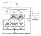
- FIG. 2is simplified diagram of the components of an LSA aggregator, in accordance with a preferred embodiment of the invention.
- FIG. 3is a flowchart of processing performed by the LSA aggregator shown in FIG. 2 .
- FIG. 4is an abstract representation of a topology data structure model.
- FIG. 5is an abstract representation of the organization of a subscription database.
- FIG. 6is a flowchart of processing performed by an LSA reflector, in accordance with a preferred embodiment of the invention.
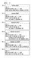
- FIG. 7is an illustrative specification of data objects exchanged between an LSA aggregator and an LSA reflector during a session.
- FIG. 1is a diagram of a packet-switched network 100 illustrating a novel and advantageous approach to network topology tracking, in accordance with a preferred embodiment of the invention.
- the packet-switched network 100comprises a plurality of routers 111 - 127 connected, as shown in FIG. 1 , to form an arbitrary topology.
- the routers 111 - 127are assumed, for purposes of the description herein, to be part of a single autonomous system and utilizing a link state routing protocol such as OSPF. Accordingly, as is known in the art, it is advantageous to divide the OSPF domain into areas: a backbone area 101 which provides connectivity to one or more non-backbone areas, e.g. areas 102 , 103 , 104 in FIG. 1 .
- Every link in the networkis assigned to exactly one area. Routers that have links to multiple areas are referred to in the art as border routers, e.g. border routers 115 , 116 , 119 , 120 , 123 , 124 in FIG. 1 . Every router 111 - 127 need only maintain a copy of the topology graph for each area to which it is connected. The routers 111 - 127 utilize reliable flooding of LSAs to distribute topology information.
- the task of collecting topology information and synthesizing a global view of the network topologyis divided into two principal functional components: referred to by the inventors as an LSA “aggregator” (“LSAG”) 150 and one or more LSA “reflectors” (“LSAR”s) 161 , 162 , 163 .
- LSA reflectors 161 , 162 , 163are responsible for collecting LSA information that a link state protocol such as OSPF naturally floods throughout each network area to ensure that the routers arrive at a common view of the network topology.
- Each LSA reflectorforwards that information to the LSA aggregator which “aggregates” the topology view of each LSA reflector into a single view of the entire OSPF domain.
- Separating the LSAR and LSAG functionsadvantageously provides a degree of fault isolation; each function can be simplified and replicated independently to increase overall reliability. Another benefit is that the LSAG may subscribe to a subset of the LSAs, for example, just the router and network LSAs for a given OSPF area.
- separating the LSAG from the LSAR functionallows a network operator to conduct significant modifications to the LSAG, e.g. as new functionalities are added, without disturbing the operation of the LSARs.
- LSA aggregator 150The structure and operation of the LSA aggregator 150 and the LSA reflectors 161 , 162 , 163 are explained in further detail herein.
- the LSA AGGREGATORis responsible for handling all complex logic in tracking the network topology: e.g., storing and managing the topology updates, filling in an appropriate topology data model, and providing advantageous application programming interfaces to applications that require network topology views.
- FIG. 2shows a high-level architectural view of an advantageous embodiment of an LSA aggregator 200 .
- the LSAG 200can be a conventional server computer—typically comprising a storage device 250 , a network interface 220 , all connected to one or more central processing units 210 operating under the control of software program instructions stored in a memory unit 240 .
- the storage device 250is typically a fast hard disk, which is utilized by the central processing unit 210 to store three main databases: a topology view 251 , a subscription database 252 , and a configuration database 253 . It is advantageous to roughly divide the software program instructions into two main program modules: a subscription manager 241 and a session manager 242 .
- the session manager 242performs the task of managing communication sessions with the various LSARs.
- FIG. 3sets forth a simplified flowchart of the processing performed by the LSAG, as the session manager checks for various session events.
- the session managerestablishes a set of initial sessions with the LSARs per the direction of the subscription manager.
- the LSAGcan use its network interface(s) to establish TCP connections to the relevant LSAR(s).
- the LSAG and the LSARcan communicate using an advantageous message protocol, such as the LSAG-LSAR protocol described in further detail below.
- the session managermonitors the sessions for any incoming messages. If a message has arrived, the session manager will proceed to process the message, depending on the message contents.
- the session managerwill update the subscription database, as described in further detail herein.
- the session managerwill update the topology view, where the LSAR communicates a message indicating a change to the network topology.
- the session managerwill notify the subscription manager when any relevant changes to the topology or to the subscriptions have occurred.
- the session managermanages the sessions, for example by sending “keep-alive” messages to an LSAR, resetting connection timers, etc.
- the session managerprocesses any directives received from the subscription manager, including any directives to establish a new session or close an existing session with an LSAR.
- FIG. 4shows an abstract representation of an advantageous topology data structure model maintained by the LSAG. Five data types are used to store the topology information. The structures and their relationships are shown in FIG. 4 .
- the TopArea 401 structurecontains information related to an OSPF area, such as the area-id. Structures TopRouter 402 and TopNetwork 403 represent a router and a network (e.g., a local area network) in the area.
- Each TopArea 401 nodecontains a set of TopRouter 402 and TopNetwork 403 nodes, thereby representing all the routers and networks in the area.
- the structure—TopInterface 404represents a single physical interface on a router.
- each TopRouter 402 nodehas a set of TopInterface 404 nodes corresponding to all the interfaces the router has in the given area.
- the structures TopLinkrepresents a link between a router-router pair 405 or a router-network pair 406 . Separate structures are designated for an interface and a link because OSPF allows multiple logical links over a single physical link, e.g. in the case of point-to-multipoint links.
- a TopNetwork 403 nodedirectly stores its set of TopLink nodes.
- Each link noderepresents a unidirectional link with its OSPF weight.
- the linkalso stores a reference to its local end which could be a TopInterface node or a TopNetwork node, and a reference to its remote node which could be a—TopRouter or a TopNetwork node.
- the linkalso stores a reference to the reverse link if one exists. Note that a link can exist between a pair of routers or between a router and a network but not between a pair of networks.
- the aims of the data structure design in FIG. 4are simplicity and generality. It is advantageous for the structure to mirror those of the OSPF builds in the routers' link state databases, thereby allowing easy verification and comparison of the functionality of different implementations. Alternative structures may also be utilized that are better adapted to rapid search or other applications.
- the subscription manager 241decides which LSAR to contact and what network areas to subscribe for.
- the subscription database 252contains this subscription related information, for example in a database structure organized as shown in FIG. 5 .
- the sub_info structureis indexed by both the area ID and the router ID of an LSAR.
- the sub_info structurebasically has two parameters: attached which indicates whether the associated LSAR is attached to the corresponding area; and subscribed which indicates whether the LSAG has subscribed to the LSAR for the area or not. These two parameters are orthogonal to each other, so there are four possible combinations.
- the subscription databaseshould keep all entries for which—attached and subscribed both have a value of “yes”, but it is also advantageous to the subscription manager to keep other entries.
- the subscription managercan lookup entries which are attached to a given area but to which it is not subscribed in order to subscribe to the area at some later time when another subscribed LSAR finds itself detached from the area.
- the structure shown in FIG. 5is merely illustrative; although area_info and rtr_info structures are shown arranged in a doubly linked list, they can be readily implemented in other more efficient structure such as a Patricia tree.
- the session manager 242As the session manager 242 receives various messages from the LSARs, it updates the subscription database 252 . Any changes, for example in the attached or subscribed parameter, are communicated back to the subscription manager 241 . In accordance with an embodiment of another aspect of the invention, the subscription manager 241 can then run a “decision” algorithm to select a course of action. For example and without limitation, consider an LSAG that has established a session with an LSAR and has subscribed for some given area A. At some point, the LSAR gets detached from area A and sends this information to the LSAG using the protocol described below. This message is received by the session manager 242 which then updates the subscription database 252 and informs the subscription manager 241 of this change.
- the subscription manager 241can then ask the session manager 242 to establish a session with some other LSAR to subscribe for area A.
- the subscription manager 241can consult the configuration database 253 to find what LSAR to contact for area A, or it can base its decision by looking at the topology view itself. More sophisticated decision algorithms may be readily implemented which advantageously require little to no intervention from a human operator.
- the LSA reflector 161 , 162 , 163 in FIG. 1is responsible for collecting and forwarding topology information to the LSAG 150 .
- link state informationThere are a number of possible ways to obtain such link state information.
- One way, for example,is by having the LSAR passively snoop on the LSAs that flow around the network.
- Another more advantageous wayis to passively participate in the LSA flooding process without actively participating in the forwarding of packets, e.g. by establishing an “adjacency” with a router in the network. This approach exploits the stream of LSAs that OSPF already reliably floods throughout the network while minimizing possible disturbances to the operational network.
- Such an embodimentmay be readily constructed by modifying a conventional OSPF hardware router or OSPF routing software such as GateD or Zebra. Such modifications preferably include the following:
- the main design goal for the LSARis that it be passive. Though the LSAR “speaks” OSPF, it should not behave as a real router and it must not be involved in packet forwarding. No other router in the network should send data packets to the LSAR to be forwarded elsewhere.
- a natural line of defense against having the LSAR participate in normal forwardingis to use router configuration measures—assign effectively infinite OSPF weights to the links to the LSARs, and install on neighbor routers strict access control lists and route filters.
- a more preferable methodis to exploit standardized features of the OSPF protocol that permit links to the LSAR to carry LSAs from the routers, but do not permit neighbors to accept LSAs from the LSAR. This can be accomplished by keeping the LSAR-router adjacency in essentially a “hanging” state such that the two ends start the database synchronization but never finish it.
- One method to achieve thisis to have the LSAR originate an LSA L and inform the router that it has this LSA during the synchronization process but never actually send it out to the router. This ensures that the database is never synchronized and hence the adjacency is never fully established from the router's perspective.
- the adjacent routernever gets to advertise a link to the LSAR in its Router LSA although it sends all the LSAs it receives to the LSAR as part of the flooding procedure.
- a side benefit of this approachis that any instability in the LSAR does not impact other routers in the network. Based on practical experience with various commercial router implementations, the inventors have not seen any alarms generated by this procedure; the only side effect of this hanging adjacency appears to be repeated link state request packets sent by the router to acquire the LSA L from the LSAR.
- FIG. 6is a flowchart of processing performed by an LSAR, in accordance with a preferred embodiment of an aspect of the invention.
- the LSARestablishes an adjacency with a router in the area it is supposed to monitor, e.g. by using the procedure described above.
- the LSARchecks to see if it has received any subscription messages from an LSAG. If it has, it updates a subscription list and includes the area id for which it is to be subscribed at step 603 .
- the LSARsends its existing link state database to the subscribing LSAG.
- the LSARchecks for any messages from an LSAG to unsubscribe. If any such message is received, then at step 606 the LSAR proceeds to remove the LSAG and the associated area from its subscription list. Finally, at step 607 , the LSAR checks to see if it has received any LSA associated with a subscribed area on the subscription list. If it has received such an LSA, then at step 608 the LSAR forwards it to the relevant LSAG on the subscription list using the LSAG-LSAR protocol described below. Accordingly, for every area in the subscription list associated with an LSAG, the LSAR sends every LSA that it accepts into the area's link state database to the LSAG.
- the above LSAR architectureadvantageously does not require any modifications to existing conventional routers in a pre-existing packet-switched network. It should be noted however that the function of the LSAR can be readily incorporated into that of a conventional router. The router need only by enhanced to implement the LSAG-LSAR protocol described below.
- FIG. 7sets forth a useful specification of object formats to be exchanged between the LSAG and the LSAR.
- the objectscan be encapsulated in one or more messages and sent over a TCP connection.
- Each messagecan contain a header, for example, which specifies a destination ID, a source ID, and a length. Where the destination/source is an LSAR, its ID should be its OSPF router ID. Where the destination/source is an LSAG, it should be the IP address of one of its interfaces. It is recommended that the LSAG uses the same IP address in all the messages it generates.
- the objects shown in FIG. 7can be encoded, e.g., in a type-length-value format.
- a sessionis initiated by an LSAG: the LSAG acts as a client and the LSAR acts as a server in the session.
- the HoldTime object 701is useful for managing sessions between an LSAG and the LSARs. Once a session has been established, each end can ensure that it sends at least one message within a “keep alive” period. At the end of the period if a node does not have an object to send, it sends an empty message. If a node does not receive any message from the other end with a value specified in a HoldTime object, it assumes that the other end is dead and terminates the session.
- the LSAGcan subscribe or unsubscribe to the LSAR for any area at any time using the Subscribe object 702 and the Unsubscribe object 703 respectively.
- the area IDcan be represented the same way it is in OSPF.
- a special wild-cardcan be used when the LSAG wants to subscribe for all the areas the LSAR is attached.
- the LSARkeeps track of all the areas the LSAG is currently subscribing for in a subscription list. The LSAR may not be attached to all of the areas that the LSAG is subscribing for. If that is the case, the LSAR sends back a message with a Detached-area object 704 .
- the LSARgets attached to an area at some point, it sends an Attached-area object 705 to the LSAG.
- the LSARsends every LSA that it accepts into an area's link state database where the area is in the subscription list associated with an LSAG. These LSAs are sent out in TopologyInfo objects 706 .
- the present inventioncan be readily extended to MPLS and variations on MPLS (such as MPLambdaS or GMPLS) which employ interior gateway protocols such as OSPF for topology discovery.
- MPLSsuch as MPLambdaS or GMPLS
- interior gateway protocolssuch as OSPF for topology discovery.
Landscapes
- Engineering & Computer Science (AREA)
- Computer Networks & Wireless Communication (AREA)
- Signal Processing (AREA)
- Data Exchanges In Wide-Area Networks (AREA)
Abstract
Description
- 1. The LSAR should not originate any LSAs other than as indicated below to establish an adjacency with a router. The LSAR does not send out any link state update packets, which ensures that its router LSA never actually goes out.
- 2. The LSAR should not perform any shortest path first computation.
- 3. The LSAR should not take part in flooding. So, even if it is connected to two routers and receives a new instance of an LSA from one of the routers, it should not flood the LSA out to the other router. This is consistent with the fact that the LSAR does not send out any link state update packets.
- 4. The LSAR should not refresh LSAs, although it ages the LSAs while they reside in the link state database like a normal OSPF router. Since LSAR does not refresh LSAs, it never flushes an LSA out when its age reaches MaxAge, typically 1 hour.
- 5. The LSAR should not be allowed to become the designated router (DR) or the backup DR (BDR) on a local area network even if the configuration file specifies a non-zero priority for it.
- 6. The LSAR should accept any LSA it receives irrespective of whether the copy of the LSA is newer or older than the received copy.
- 7. The LSAR should not describe any LSAs in the Database Description packets other than its own Router LSA (described in database exchange but never transmitted over the link).
Claims (9)
Priority Applications (1)
| Application Number | Priority Date | Filing Date | Title |
|---|---|---|---|
| US11/695,352US7835303B2 (en) | 2001-05-21 | 2007-04-02 | Packet-switched network topology tracking method and system |
Applications Claiming Priority (3)
| Application Number | Priority Date | Filing Date | Title |
|---|---|---|---|
| US29241501P | 2001-05-21 | 2001-05-21 | |
| US10/063,867US7200120B1 (en) | 2001-05-21 | 2002-05-21 | Packet-switched network topology tracking method and system |
| US11/695,352US7835303B2 (en) | 2001-05-21 | 2007-04-02 | Packet-switched network topology tracking method and system |
Related Parent Applications (1)
| Application Number | Title | Priority Date | Filing Date |
|---|---|---|---|
| US10/063,867ContinuationUS7200120B1 (en) | 2001-05-21 | 2002-05-21 | Packet-switched network topology tracking method and system |
Publications (2)
| Publication Number | Publication Date |
|---|---|
| US20070165546A1 US20070165546A1 (en) | 2007-07-19 |
| US7835303B2true US7835303B2 (en) | 2010-11-16 |
Family
ID=37897642
Family Applications (2)
| Application Number | Title | Priority Date | Filing Date |
|---|---|---|---|
| US10/063,867Expired - LifetimeUS7200120B1 (en) | 2001-05-21 | 2002-05-21 | Packet-switched network topology tracking method and system |
| US11/695,352Expired - LifetimeUS7835303B2 (en) | 2001-05-21 | 2007-04-02 | Packet-switched network topology tracking method and system |
Family Applications Before (1)
| Application Number | Title | Priority Date | Filing Date |
|---|---|---|---|
| US10/063,867Expired - LifetimeUS7200120B1 (en) | 2001-05-21 | 2002-05-21 | Packet-switched network topology tracking method and system |
Country Status (1)
| Country | Link |
|---|---|
| US (2) | US7200120B1 (en) |
Families Citing this family (28)
| Publication number | Priority date | Publication date | Assignee | Title |
|---|---|---|---|---|
| US8510468B2 (en) | 2000-04-17 | 2013-08-13 | Ciradence Corporation | Route aware network link acceleration |
| US6836465B2 (en)* | 2001-11-29 | 2004-12-28 | Ipsum Networks, Inc. | Method and system for path identification in packet networks |
| US7860024B1 (en) | 2001-05-21 | 2010-12-28 | At&T Intellectual Property Ii, L.P. | Network monitoring method and system |
| US7200120B1 (en)* | 2001-05-21 | 2007-04-03 | At&T Corp. | Packet-switched network topology tracking method and system |
| GB2388490A (en)* | 2002-05-07 | 2003-11-12 | Marconi Comm Ltd | Monitoring the state of a communications network |
| US7539210B2 (en)* | 2002-05-17 | 2009-05-26 | Telefonaktiebolaget L M Ericcson (Publ) | Dynamic routing in packet-switching multi-layer communications networks |
| US7355986B2 (en)* | 2002-10-22 | 2008-04-08 | Sandia Corporation | Reconfigureable network node |
| US7983239B1 (en)* | 2003-01-07 | 2011-07-19 | Raytheon Bbn Technologies Corp. | Systems and methods for constructing a virtual model of a multi-hop, multi-access network |
| US7881229B2 (en) | 2003-08-08 | 2011-02-01 | Raytheon Bbn Technologies Corp. | Systems and methods for forming an adjacency graph for exchanging network routing data |
| US7606927B2 (en) | 2003-08-27 | 2009-10-20 | Bbn Technologies Corp | Systems and methods for forwarding data units in a communications network |
| US20050083964A1 (en)* | 2003-10-15 | 2005-04-21 | Tatman Lance A. | Method and system for the centralized collection of link state routing protocol data |
| US7668083B1 (en) | 2003-10-28 | 2010-02-23 | Bbn Technologies Corp. | Systems and methods for forwarding data in a communications network |
| US7801857B2 (en)* | 2003-12-19 | 2010-09-21 | Solace Systems, Inc. | Implicit routing in content based networks |
| US7599349B2 (en)* | 2004-01-29 | 2009-10-06 | Cisco Technology, Inc. | Computing inter-autonomous system MPLS traffic engineering LSP paths |
| US20060029035A1 (en)* | 2004-03-25 | 2006-02-09 | Chase Christopher J | Method and apparatus for selecting routes for distribution within IP networks |
| JP4408756B2 (en)* | 2004-06-30 | 2010-02-03 | 富士通株式会社 | Route calculation system |
| KR100674086B1 (en)* | 2004-12-16 | 2007-01-24 | 한국전자통신연구원 | Topology Discovery Method in Ethernet Network |
| US8228818B2 (en) | 2005-06-24 | 2012-07-24 | At&T Intellectual Property Ii, Lp | Systems, methods, and devices for monitoring networks |
| US9191396B2 (en)* | 2005-09-08 | 2015-11-17 | International Business Machines Corporation | Identifying source of malicious network messages |
| US8521904B1 (en) | 2008-12-16 | 2013-08-27 | At&T Intellectual Property I, L.P. | Devices, systems, and/or methods for determining internet topology |
| US8139504B2 (en) | 2009-04-07 | 2012-03-20 | Raytheon Bbn Technologies Corp. | System, device, and method for unifying differently-routed networks using virtual topology representations |
| US20110289119A1 (en)* | 2010-05-20 | 2011-11-24 | Sybase, Inc. | Methods and systems for monitoring server cloud topology and resources |
| EP2586157B1 (en)* | 2010-06-28 | 2019-08-07 | Telefonaktiebolaget LM Ericsson (publ) | Network management |
| CN104168154B (en)* | 2014-07-31 | 2018-01-02 | 中国人民解放军91655部队 | The multi-level network system and its construction method of network-oriented Situation Awareness |
| CN106330511B (en)* | 2015-06-30 | 2020-06-09 | 中兴通讯股份有限公司 | Network element equipment and method for opening data communication network |
| CN105049345B (en)* | 2015-07-22 | 2018-03-30 | 中国科学院计算技术研究所 | A kind of method and system of BGP routing traffics data fusion |
| CN107959627B (en)* | 2016-10-14 | 2021-02-12 | 华为技术有限公司 | Address transmission method and network equipment |
| US10326794B2 (en)* | 2016-12-21 | 2019-06-18 | Verisign, Inc. | Anycast-based spoofed traffic detection and mitigation |
Citations (29)
| Publication number | Priority date | Publication date | Assignee | Title |
|---|---|---|---|---|
| US5331637A (en) | 1993-07-30 | 1994-07-19 | Bell Communications Research, Inc. | Multicast routing using core based trees |
| US5546540A (en) | 1991-01-14 | 1996-08-13 | Concord Communications, Inc. | Automatic topology monitor for multi-segment local area network |
| US5926463A (en) | 1997-10-06 | 1999-07-20 | 3Com Corporation | Method and apparatus for viewing and managing a configuration of a computer network |
| US6094682A (en) | 1998-03-13 | 2000-07-25 | Fujitsu Limited | Method of constructing the path information of a network management system |
| US20010053149A1 (en) | 2000-05-05 | 2001-12-20 | Li Mo | Method and system for quality of service (QoS) support in a packet-switched network |
| US6363319B1 (en) | 1999-08-31 | 2002-03-26 | Nortel Networks Limited | Constraint-based route selection using biased cost |
| US20020141378A1 (en) | 2001-03-28 | 2002-10-03 | Bays Robert James | Methods, apparatuses and systems facilitating deployment, support and configuration of network routing policies |
| US20020163884A1 (en) | 2001-05-03 | 2002-11-07 | Amir Peles | Controlling traffic on links between autonomous systems |
| US20020176359A1 (en) | 2001-05-08 | 2002-11-28 | Sanja Durinovic-Johri | Apparatus for load balancing in routers of a network using overflow paths |
| US20020196802A1 (en) | 1998-02-26 | 2002-12-26 | Joshua Sakov | Data forwarding method and apparatus |
| US20030026212A1 (en) | 2001-05-18 | 2003-02-06 | Martin Daniel J. | Method and system for determining network characteristics using routing protocols |
| US20030026268A1 (en) | 2000-11-28 | 2003-02-06 | Siemens Technology-To-Business Center, Llc | Characteristic routing |
| US20030058804A1 (en) | 1999-01-15 | 2003-03-27 | Ali Saleh | Method of reducing traffic during path restoration |
| US6574663B1 (en)* | 1999-08-31 | 2003-06-03 | Intel Corporation | Active topology discovery in active networks |
| US6600724B1 (en) | 1998-04-28 | 2003-07-29 | Cisco Technology, Inc. | Routing table structures |
| US6650626B1 (en) | 1999-12-10 | 2003-11-18 | Nortel Networks Limited | Fast path forwarding of link state advertisements using a minimum spanning tree |
| US6728214B1 (en) | 1999-07-28 | 2004-04-27 | Lucent Technologies Inc. | Testing of network routers under given routing protocols |
| US6751660B1 (en) | 2000-05-31 | 2004-06-15 | Cisco Technology, Inc. | Network management systems that receive cross connect and/or other circuit information from network elements |
| US6820134B1 (en)* | 2000-12-28 | 2004-11-16 | Cisco Technology, Inc. | Optimizing flooding of information in link-state routing protocol |
| US6823395B1 (en) | 1999-09-14 | 2004-11-23 | Telefonaktiebolaget Lm Ericsson (Publ) | Arrangement and method relating to routing in a network |
| US6871235B1 (en) | 1999-12-10 | 2005-03-22 | Nortel Networks Limited | Fast path forwarding of link state advertisements using reverse path forwarding |
| US20050099958A1 (en) | 2003-11-06 | 2005-05-12 | Tekelec | Methods and systems for automated analysis of signaling link utilization |
| US20050198250A1 (en) | 2001-04-06 | 2005-09-08 | Terited International, Inc. | Network system, method and protocols for hierarchical service and content distribution via directory enabled network |
| US6944159B1 (en) | 2001-04-12 | 2005-09-13 | Force10 Networks, Inc. | Method and apparatus for providing virtual point to point connections in a network |
| US6944675B2 (en) | 2000-04-18 | 2005-09-13 | Nec Corporation | QoS-based shortest path routing for hierarchical communication network |
| US6980537B1 (en) | 1999-11-12 | 2005-12-27 | Itt Manufacturing Enterprises, Inc. | Method and apparatus for communication network cluster formation and transmission of node link status messages with reduced protocol overhead traffic |
| US6985959B1 (en) | 2000-11-01 | 2006-01-10 | Nortel Networks Limited | Constraint route dissemination using distributed route exchanges |
| US20060069779A1 (en) | 2000-09-05 | 2006-03-30 | Operax Ab | Method for, and a topology aware resource manager in an IP-telephony system |
| US7200120B1 (en) | 2001-05-21 | 2007-04-03 | At&T Corp. | Packet-switched network topology tracking method and system |
- 2002
- 2002-05-21USUS10/063,867patent/US7200120B1/ennot_activeExpired - Lifetime
- 2007
- 2007-04-02USUS11/695,352patent/US7835303B2/ennot_activeExpired - Lifetime
Patent Citations (33)
| Publication number | Priority date | Publication date | Assignee | Title |
|---|---|---|---|---|
| US5546540A (en) | 1991-01-14 | 1996-08-13 | Concord Communications, Inc. | Automatic topology monitor for multi-segment local area network |
| US5331637A (en) | 1993-07-30 | 1994-07-19 | Bell Communications Research, Inc. | Multicast routing using core based trees |
| US5926463A (en) | 1997-10-06 | 1999-07-20 | 3Com Corporation | Method and apparatus for viewing and managing a configuration of a computer network |
| US20020196802A1 (en) | 1998-02-26 | 2002-12-26 | Joshua Sakov | Data forwarding method and apparatus |
| US6094682A (en) | 1998-03-13 | 2000-07-25 | Fujitsu Limited | Method of constructing the path information of a network management system |
| US6600724B1 (en) | 1998-04-28 | 2003-07-29 | Cisco Technology, Inc. | Routing table structures |
| US20030058804A1 (en) | 1999-01-15 | 2003-03-27 | Ali Saleh | Method of reducing traffic during path restoration |
| US7002917B1 (en) | 1999-01-15 | 2006-02-21 | Cisco Technology, Inc. | Method for path selection in a network |
| US6728214B1 (en) | 1999-07-28 | 2004-04-27 | Lucent Technologies Inc. | Testing of network routers under given routing protocols |
| US6363319B1 (en) | 1999-08-31 | 2002-03-26 | Nortel Networks Limited | Constraint-based route selection using biased cost |
| US6574663B1 (en)* | 1999-08-31 | 2003-06-03 | Intel Corporation | Active topology discovery in active networks |
| US6823395B1 (en) | 1999-09-14 | 2004-11-23 | Telefonaktiebolaget Lm Ericsson (Publ) | Arrangement and method relating to routing in a network |
| US6980537B1 (en) | 1999-11-12 | 2005-12-27 | Itt Manufacturing Enterprises, Inc. | Method and apparatus for communication network cluster formation and transmission of node link status messages with reduced protocol overhead traffic |
| US6871235B1 (en) | 1999-12-10 | 2005-03-22 | Nortel Networks Limited | Fast path forwarding of link state advertisements using reverse path forwarding |
| US6650626B1 (en) | 1999-12-10 | 2003-11-18 | Nortel Networks Limited | Fast path forwarding of link state advertisements using a minimum spanning tree |
| US6944675B2 (en) | 2000-04-18 | 2005-09-13 | Nec Corporation | QoS-based shortest path routing for hierarchical communication network |
| US20010053149A1 (en) | 2000-05-05 | 2001-12-20 | Li Mo | Method and system for quality of service (QoS) support in a packet-switched network |
| US6751660B1 (en) | 2000-05-31 | 2004-06-15 | Cisco Technology, Inc. | Network management systems that receive cross connect and/or other circuit information from network elements |
| US20060069779A1 (en) | 2000-09-05 | 2006-03-30 | Operax Ab | Method for, and a topology aware resource manager in an IP-telephony system |
| US6985959B1 (en) | 2000-11-01 | 2006-01-10 | Nortel Networks Limited | Constraint route dissemination using distributed route exchanges |
| US20030026268A1 (en) | 2000-11-28 | 2003-02-06 | Siemens Technology-To-Business Center, Llc | Characteristic routing |
| US6820134B1 (en)* | 2000-12-28 | 2004-11-16 | Cisco Technology, Inc. | Optimizing flooding of information in link-state routing protocol |
| US7437476B2 (en) | 2000-12-28 | 2008-10-14 | Cisco Technology, Inc. | Optimizing flooding of information in link-state routing protocol |
| US20020141378A1 (en) | 2001-03-28 | 2002-10-03 | Bays Robert James | Methods, apparatuses and systems facilitating deployment, support and configuration of network routing policies |
| US20050198250A1 (en) | 2001-04-06 | 2005-09-08 | Terited International, Inc. | Network system, method and protocols for hierarchical service and content distribution via directory enabled network |
| US6944159B1 (en) | 2001-04-12 | 2005-09-13 | Force10 Networks, Inc. | Method and apparatus for providing virtual point to point connections in a network |
| US20020163884A1 (en) | 2001-05-03 | 2002-11-07 | Amir Peles | Controlling traffic on links between autonomous systems |
| US20020176359A1 (en) | 2001-05-08 | 2002-11-28 | Sanja Durinovic-Johri | Apparatus for load balancing in routers of a network using overflow paths |
| US20040233859A1 (en) | 2001-05-18 | 2004-11-25 | Martin Daniel J. | Method and system for determining network characteristics using routing protocols |
| US6744739B2 (en)* | 2001-05-18 | 2004-06-01 | Micromuse Inc. | Method and system for determining network characteristics using routing protocols |
| US20030026212A1 (en) | 2001-05-18 | 2003-02-06 | Martin Daniel J. | Method and system for determining network characteristics using routing protocols |
| US7200120B1 (en) | 2001-05-21 | 2007-04-03 | At&T Corp. | Packet-switched network topology tracking method and system |
| US20050099958A1 (en) | 2003-11-06 | 2005-05-12 | Tekelec | Methods and systems for automated analysis of signaling link utilization |
Non-Patent Citations (3)
| Title |
|---|
| A Model for Generation and Processing of Link State Information in SAAM architecture; H. Huseyin Uysal; Mar. 2000. |
| Making Qos Aware Multicast Scalable in Terms of Link State Advertisement; Toshihiko et al.; IEEE 2001. |
| Performance Analysis and Improvement of the Open Shortest Path First Routing Protocol; Mahad A. Ahmed, B. Eng; Sep. 1999. |
Also Published As
| Publication number | Publication date |
|---|---|
| US7200120B1 (en) | 2007-04-03 |
| US20070165546A1 (en) | 2007-07-19 |
Similar Documents
| Publication | Publication Date | Title |
|---|---|---|
| US7835303B2 (en) | Packet-switched network topology tracking method and system | |
| US10673741B2 (en) | Control device discovery in networks having separate control and forwarding devices | |
| EP2933979B1 (en) | Dht-based control network implementation method and system, and network controller | |
| US9667524B2 (en) | Method to check health of automatically discovered controllers in software defined networks (SDNs) | |
| US7065059B1 (en) | Technique for restoring adjacencies in OSPF in a non-stop forwarding intermediate node of a computer network | |
| JP4790376B2 (en) | Separation of SoftRouter protocol | |
| US7801857B2 (en) | Implicit routing in content based networks | |
| US8351438B2 (en) | Flooding-based routing protocol having database pruning and rate-controlled state refresh | |
| US7752024B2 (en) | Systems and methods for constructing multi-layer topological models of computer networks | |
| US6757258B1 (en) | Method and apparatus for reducing OSPF flooding | |
| US20090245137A1 (en) | Highly available virtual stacking architecture | |
| US9647928B2 (en) | OSPF point-to-multipoint over broadcast or NBMA mode | |
| US6950427B1 (en) | Technique for resynchronizing LSDB in OSPF after a software reload in a non-stop forwarding intermediate node of a computer network | |
| JP2006229967A (en) | Fast multicast path switching | |
| KR101464790B1 (en) | How to Compute Extension Trees Based on Link State Advertisements (LSA), Bridges and Computer Networks | |
| WO2005018175A2 (en) | Method and apparatus for adaptive flow-based routing in multi-stage data networks | |
| WO2001086844A1 (en) | Systems and methods for constructing multi-layer topological models of computer networks | |
| US7860024B1 (en) | Network monitoring method and system | |
| EP1185041B1 (en) | OSPF autonomous system with a backbone divided into two sub-areas | |
| WO2002006918A2 (en) | A method, system, and product for preventing data loss and forwarding loops when conducting a scheduled change to the topology of a link-state routing protocol network | |
| Cisco | Logical Object Dialog Boxes | |
| Cisco | Logical Object Dialog Boxes | |
| Cisco | Logical Dialog Boxes | |
| JP2009130421A (en) | Mesh network using flooding relay packet system and nodes used in the network | |
| Sharma | Programmable Ethernet Switch Networks and Their Applications |
Legal Events
| Date | Code | Title | Description |
|---|---|---|---|
| FEPP | Fee payment procedure | Free format text:PAYOR NUMBER ASSIGNED (ORIGINAL EVENT CODE: ASPN); ENTITY STATUS OF PATENT OWNER: LARGE ENTITY | |
| STCF | Information on status: patent grant | Free format text:PATENTED CASE | |
| FEPP | Fee payment procedure | Free format text:PAYER NUMBER DE-ASSIGNED (ORIGINAL EVENT CODE: RMPN); ENTITY STATUS OF PATENT OWNER: LARGE ENTITY Free format text:PAYOR NUMBER ASSIGNED (ORIGINAL EVENT CODE: ASPN); ENTITY STATUS OF PATENT OWNER: LARGE ENTITY | |
| AS | Assignment | Owner name:AT&T PROPERTIES, LLC, NEVADA Free format text:ASSIGNMENT OF ASSIGNORS INTEREST;ASSIGNOR:AT&T CORP.;REEL/FRAME:032246/0586 Effective date:20140205 Owner name:AT&T INTELLECTUAL PROPERTY II, L.P., GEORGIA Free format text:ASSIGNMENT OF ASSIGNORS INTEREST;ASSIGNOR:AT&T PROPERTIES, LLC;REEL/FRAME:032248/0355 Effective date:20140207 | |
| FPAY | Fee payment | Year of fee payment:4 | |
| AS | Assignment | Owner name:ASHBOURNE TECHNOLOGIES, LLC, DELAWARE Free format text:ASSIGNMENT OF ASSIGNORS INTEREST;ASSIGNOR:AT&T INTELLECTUAL PROPERTY II, L.P.;REEL/FRAME:033443/0346 Effective date:20140610 | |
| MAFP | Maintenance fee payment | Free format text:PAYMENT OF MAINTENANCE FEE, 8TH YEAR, LARGE ENTITY (ORIGINAL EVENT CODE: M1552) Year of fee payment:8 | |
| MAFP | Maintenance fee payment | Free format text:PAYMENT OF MAINTENANCE FEE, 12TH YEAR, LARGE ENTITY (ORIGINAL EVENT CODE: M1553); ENTITY STATUS OF PATENT OWNER: LARGE ENTITY Year of fee payment:12 |