US7835074B2 - Mini-scope for multi-directional imaging - Google Patents
Mini-scope for multi-directional imagingDownload PDFInfo
- Publication number
- US7835074B2 US7835074B2US11/810,702US81070207AUS7835074B2US 7835074 B2US7835074 B2US 7835074B2US 81070207 AUS81070207 AUS 81070207AUS 7835074 B2US7835074 B2US 7835074B2
- Authority
- US
- United States
- Prior art keywords
- mini
- optical
- scope
- optical energy
- selective
- Prior art date
- Legal status (The legal status is an assumption and is not a legal conclusion. Google has not performed a legal analysis and makes no representation as to the accuracy of the status listed.)
- Active, expires
Links
- 238000003384imaging methodMethods0.000titleclaimsabstractdescription47
- 230000003287optical effectEffects0.000claimsabstractdescription162
- 238000005286illuminationMethods0.000claimsabstractdescription32
- 239000004020conductorSubstances0.000claimsabstractdescription18
- 230000004044responseEffects0.000claimsabstractdescription13
- 238000000034methodMethods0.000claimsdescription20
- 238000012545processingMethods0.000claimsdescription16
- 230000010287polarizationEffects0.000claimsdescription14
- 238000001454recorded imageMethods0.000claimsdescription14
- 239000007787solidSubstances0.000claimsdescription11
- 239000013307optical fiberSubstances0.000claimsdescription5
- 238000004891communicationMethods0.000claimsdescription3
- 238000000060site-specific infrared dichroism spectroscopyMethods0.000abstractdescription19
- 230000001902propagating effectEffects0.000abstractdescription3
- 230000003319supportive effectEffects0.000description7
- 230000006870functionEffects0.000description4
- 239000000463materialSubstances0.000description3
- 239000004065semiconductorSubstances0.000description2
- 229910000530Gallium indium arsenideInorganic materials0.000description1
- 239000000919ceramicSubstances0.000description1
- 238000006243chemical reactionMethods0.000description1
- 230000000295complement effectEffects0.000description1
- 150000001875compoundsChemical class0.000description1
- 238000013461designMethods0.000description1
- 238000009472formulationMethods0.000description1
- 239000011521glassSubstances0.000description1
- 238000002347injectionMethods0.000description1
- 239000007924injectionSubstances0.000description1
- 238000005259measurementMethods0.000description1
- 229910044991metal oxideInorganic materials0.000description1
- 150000004706metal oxidesChemical class0.000description1
- 239000000203mixtureSubstances0.000description1
- 238000012986modificationMethods0.000description1
- 230000004048modificationEffects0.000description1
- 239000004033plasticSubstances0.000description1
- 229920003023plasticPolymers0.000description1
- 230000008569processEffects0.000description1
- 238000001228spectrumMethods0.000description1
Images


Classifications
- G—PHYSICS
- G02—OPTICS
- G02B—OPTICAL ELEMENTS, SYSTEMS OR APPARATUS
- G02B23/00—Telescopes, e.g. binoculars; Periscopes; Instruments for viewing the inside of hollow bodies; Viewfinders; Optical aiming or sighting devices
- G02B23/24—Instruments or systems for viewing the inside of hollow bodies, e.g. fibrescopes
- G02B23/2407—Optical details
- G02B23/2423—Optical details of the distal end
- A—HUMAN NECESSITIES
- A61—MEDICAL OR VETERINARY SCIENCE; HYGIENE
- A61B—DIAGNOSIS; SURGERY; IDENTIFICATION
- A61B1/00—Instruments for performing medical examinations of the interior of cavities or tubes of the body by visual or photographical inspection, e.g. endoscopes; Illuminating arrangements therefor
- A61B1/00163—Optical arrangements
- A61B1/00174—Optical arrangements characterised by the viewing angles
- A61B1/00181—Optical arrangements characterised by the viewing angles for multiple fixed viewing angles
- A—HUMAN NECESSITIES
- A61—MEDICAL OR VETERINARY SCIENCE; HYGIENE
- A61B—DIAGNOSIS; SURGERY; IDENTIFICATION
- A61B1/00—Instruments for performing medical examinations of the interior of cavities or tubes of the body by visual or photographical inspection, e.g. endoscopes; Illuminating arrangements therefor
- A61B1/00163—Optical arrangements
- A61B1/00174—Optical arrangements characterised by the viewing angles
- A61B1/00183—Optical arrangements characterised by the viewing angles for variable viewing angles
- A—HUMAN NECESSITIES
- A61—MEDICAL OR VETERINARY SCIENCE; HYGIENE
- A61B—DIAGNOSIS; SURGERY; IDENTIFICATION
- A61B1/00—Instruments for performing medical examinations of the interior of cavities or tubes of the body by visual or photographical inspection, e.g. endoscopes; Illuminating arrangements therefor
- A61B1/04—Instruments for performing medical examinations of the interior of cavities or tubes of the body by visual or photographical inspection, e.g. endoscopes; Illuminating arrangements therefor combined with photographic or television appliances
- A61B1/05—Instruments for performing medical examinations of the interior of cavities or tubes of the body by visual or photographical inspection, e.g. endoscopes; Illuminating arrangements therefor combined with photographic or television appliances characterised by the image sensor, e.g. camera, being in the distal end portion
- G—PHYSICS
- G02—OPTICS
- G02B—OPTICAL ELEMENTS, SYSTEMS OR APPARATUS
- G02B23/00—Telescopes, e.g. binoculars; Periscopes; Instruments for viewing the inside of hollow bodies; Viewfinders; Optical aiming or sighting devices
- G02B23/24—Instruments or systems for viewing the inside of hollow bodies, e.g. fibrescopes
- G02B23/2476—Non-optical details, e.g. housings, mountings, supports
- G02B23/2484—Arrangements in relation to a camera or imaging device
- H—ELECTRICITY
- H04—ELECTRIC COMMUNICATION TECHNIQUE
- H04N—PICTORIAL COMMUNICATION, e.g. TELEVISION
- H04N23/00—Cameras or camera modules comprising electronic image sensors; Control thereof
- H04N23/50—Constructional details
- H04N23/555—Constructional details for picking-up images in sites, inaccessible due to their dimensions or hazardous conditions, e.g. endoscopes or borescopes
- G—PHYSICS
- G02—OPTICS
- G02B—OPTICAL ELEMENTS, SYSTEMS OR APPARATUS
- G02B27/00—Optical systems or apparatus not provided for by any of the groups G02B1/00 - G02B26/00, G02B30/00
- G02B27/10—Beam splitting or combining systems
- G02B27/14—Beam splitting or combining systems operating by reflection only
- G02B27/141—Beam splitting or combining systems operating by reflection only using dichroic mirrors
- G—PHYSICS
- G02—OPTICS
- G02B—OPTICAL ELEMENTS, SYSTEMS OR APPARATUS
- G02B27/00—Optical systems or apparatus not provided for by any of the groups G02B1/00 - G02B26/00, G02B30/00
- G02B27/28—Optical systems or apparatus not provided for by any of the groups G02B1/00 - G02B26/00, G02B30/00 for polarising
- G02B27/283—Optical systems or apparatus not provided for by any of the groups G02B1/00 - G02B26/00, G02B30/00 for polarising used for beam splitting or combining
Definitions
- the inventionis directed to a mini-scope for multi-directional imaging.
- the mini-scopeincludes an elongated mini-scope body having a flexible optical conductor.
- the flexible optical conductorhas a distal and a proximal end.
- An emissions apertureis disposed on the distal end of the elongated mini-scope body to emit a beam of optical energy propagating through the flexible optical conductor.
- a selective mirroris also disposed at the distal end of the elongated mini-scope body. The selective mirror is configured to selectively pass and/or reflect the beam of optical energy based on the optical characteristics of the beam of optical energy.
- An SSIDis also disposed at the distal end of the elongated mini-scope body for imaging illumination reflected by an external object in response to the beam of optical energy, the illumination is directed to pass through or reflect from the selective mirror to the camera based on optical characteristics of the beam.
- FIG. 1is a side view of a mini-scope in accordance with an embodiment of the present invention
- FIG. 2 a - 2 bis a side view of a mini-scope in accordance with another embodiment of the present invention.
- FIG. 3is a side view of a mini-scope emitting and imaging multiple beams of optical energy, in accordance with another embodiment of the present invention.
- FIG. 4is a side view of a mini-scope having a prism member, in accordance with another embodiment of the present invention.
- FIG. 5is a side view of a mini-scope having a plurality of selective mirrors, in accordance with another embodiment of the present invention.
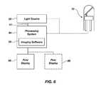
- FIG. 6is a process flow chart illustrating one embodiment of the present invention with multiple displays.
- FIG. 7is a flow chart of a method for multidirectional imaging, in accordance with another embodiment of the present invention.
- a beam of optical energyincludes reference to one or more of such beams
- an emitterincludes reference to one or more of such emitters.
- mini-scoperefers to a miniature optical instrument for examining the inner parts of the body as well as for other optical applications.
- SSIDSolid State Imaging Device
- CIDcharge-injection devices
- CCDcharge-coupled devices
- CMOScomplementary metal oxide semiconductor
- imaging devicesincluding those made from compound semiconductors such as InGaAs, capable of imaging reflected illumination of visible and/or non-visible light.
- selective mirrorrefers to a surface, having selective reflection properties, based on various characteristics of the incident optical energy. These characteristics can include, for example: wavelength, polarization, intensity, direction, angle, frequency, and other like characteristics.
- the surfacecan be planar or nonplanar as suits a particular configuration.
- a numerical range of “about 1 micrometer to about 5 micrometers”should be interpreted to include not only the explicitly recited values of about 1 micrometer to about 5 micrometers, but also include individual values and sub-ranges within the indicated range. Thus, included in this numerical range are individual values such as 2, 3, and 4 and sub-ranges such as from 1-3, from 2-4, and from 3-5, etc. This same principle applies to ranges reciting only one numerical value and should apply regardless of the breadth of the range or the characteristics being described.
- the term “about”means that dimensions, sizes, formulations, parameters, shapes and other quantities and characteristics are not and need not be exact, but may be approximated and/or larger or smaller, as desired, reflecting tolerances, conversion factors, rounding off, measurement error, and the like, and other factors known to those of skill in the art.
- a mini-scope 10in accordance with one embodiment of the invention, includes a means for optically conducting a beam of optical energy.
- This means for optically conductingcan include an elongated mini-scope body 18 having a flexible optical conductor 20 , a single optical fiber having a jacket, and the like.
- the flexible optical conductorcan be a flexible optical fiber having a substantially small diameter and being configured to transmit optical energy from one end of the mini-scope 10 to an opposite end.
- the elongated mini-scope bodyhas, for example, a distal end and a proximal end, and a length of approximately 0.1 m to 3 m, with 0.5 m being an exemplary length, and a diameter of approximately 0.5 mm to 5 mm, with 1 mm being an exemplary diameter.
- a mini-scope 10includes a source of optical energy (no shown) disposed on a distal end of the mini-scope 10 for generating a beam of optical energy at the distal end of the mini-scope 10 .
- This elongated mini-scope bodyis configured to be inserted into or in contact with a patient or device.
- the mini-scopecan further include a means for emitting a beam of optical energy, such as an emissions aperture 14 , an emissions aperture with a lens, or the like.
- An emissions aperturecan be disposed on the distal end of the elongated mini-scope body for emitting the beam of optical energy propagating through the flexible optical conductor.
- a means for selectively directing a beam of optical energycan be positioned above the emissions aperture to selectively pass and reflect the beam of optical energy 32 a based on the optical characteristics of the beam, as described in greater detail below.
- a means for imagingcan also be disposed on the distal end of the elongated mini-scope body.
- This means for imagingcan include a SSID 16 , such as a mini charge coupled device (CCD) camera, a mini CMOS camera, or another optical energy detector designed to operate at other wavelengths.
- the means for imagingcan image the illumination reflected by an external object in response to the beam of optical energy 32 b, wherein the illumination is directed to pass through or reflect from the selective mirror to the means for imaging.
- a means for selectively directing the beam of optical energycan selectively direct a beam or multiple beams of optical energy based on various optical characteristics of the beam.
- This means for selectively directingcan include a selective mirror 12 .
- the selective mirrorcan be a dichroic mirror, a polarization dependant beam splitting plate, a polarization dependant beam splitting cube, a prism, a diffraction grating, or other optical devices that can be configured to selectively pass and reflect a beam or portion of a beam of optical energy based on the properties of the optical energy.
- the mini-scope 10can provide both a forward and a lateral image to a user, without the need for turning, rotating, or redirecting the scope head and without substantially increasing the size of the scope.
- the selective mirror 12can be a dichroic mirror or a mirror which reflects or passes a beam of optical energy based on the frequency characteristics of the beam of optical energy.
- Dichroic mirrorscan be designed to reflect a specific wavelength region of optical energy.
- a dichroic mirrorcan be designed to reflect blue light (e.g., light with an optical wavelength of about 440-550 nm), but pass red light (e.g., light with an optical wavelength of about 625-740 nm).
- a mirrorcan be designed to reflect all light having a wavelength of about 450 ⁇ 10 nm, thus reflecting most blue light, while passing light with an optical frequency outside of this range.
- a dichroic mirrorcan be designed to pass and reflect other frequency regions, such as red light, or all near ultraviolet wavelength of about 380 -200 nm.
- the selective mirror 12can be a polarizing beam splitter cube or other optical element configured to pass or reflect a beam of optical energy based on the polarization characteristics of the beam.
- polarization beam splitter platesare designed to separate optical energy into the P-and S-components by passing one component and reflecting the other. This type of selective mirror can pass or reflect a spectrum of light frequencies, given constant P-or S-polarization.
- the width of the selective mirrorcan be approximately the diameter of the elongated mini-scope body, and the length can vary according to the desired angular orientation of the mirror.
- This selective mirrorcan have a variety of shapes including an ellipse, a circle, a square, a rectangle, and the like.
- the selective mirrorcan be positioned at a fixed or movable angle. For example, this angle can be a 45 degree, 15 degree angle, facing in the reverse direction, or any other angular orientations relative to the plane of the supportive end structure 28 , according to the design, usage, and type of the selective mirror.
- a mini-scope 10further includes a SSID 16 , such as a charged coupled device (CCD) camera, having a gradient refractive index (GRIN) lens 22 .
- the SSIDis configured to transmit recorded images to a processing system (not shown) via an electrical connection 26 , disposed within the elongated mini-scope body 18 . In another aspect, the images could be sent via a wireless connection to a processing system.
- the elongated mini-scope bodycan further include a supportive end structure 28 , disposed at its distal end. This supportive end structure can position the emissions aperture 14 and the SSID 16 in a forward direction.
- This structurecan further be coupled to a mirror supporting structure 24 , which holds the selective mirror 12 in position.
- the mirror supporting structurecan be configured to support and control the structure in a fixed or movable position, according to a variety of suitable structural configurations and embodiments.
- the mini-scope 10can include a rotating device (not shown) for rotating the selective mirror 12 .
- the rotating devicecan be coupled to the supportive end structure and be configured to both support, rotate and/or pivot the selective mirror, the emissions aperture 14 , and/or the SSID 16 about the center axis of the elongated mini-scope body 18 .
- the rotating devicecan also rotate the supportive end structure and/or the selective mirror in other directions, as desired.
- the supportive end structure 28 and mirror supporting structure 24can include rotational means.
- a mirror supporting structure that serves as a rotating devicecan rotate the mirror so as to increase or decrease the direction of reflection.
- This mirror supporting structurecan be made of a piezoelectric material that is configured to rotate the mirror in response to a predefined electrical condition.
- the rotating devicecan also rotate via a variety of other rotational means, including a mechanical device, electromechanical device, electromagnetic device, or other suitable device. Power for this device can be supplied through the electrical connection 26 , or through a similar connection.
- the mini-scopecan also include a transparent shield 30 , for protecting the patient and mini-scope elements.
- the shieldmay be coupled to the supportive end structure 28 and can be fabricated from various materials such as plastics, glass, ceramics, etc.
- a first beam of optical energy 32 acan be transmitted down the flexible optical conductor 20 and emitted towards the selective mirror 12 , via the emissions aperture 14 .
- the first beamcan be reflected in a lateral direction, based on the optical characteristics of the first beam.
- the selective mirrorcan be a dichroic mirror, as described above.
- the dichroic mirrorcan be positioned at a 45 degree angle relative to the emissions apertures and can be configured to reflect all light having a wavelength of approximately 450 ⁇ 10 nm (blue light).
- the first beam 32 ahas a wavelength of approximately 450 nm
- the beamcan be reflected by the dichroic mirror in a lateral direction, based on the optical characteristics of the first beam, as shown.
- the illumination 32 b reflected by an external object (not shown) in a reverse-lateral direction, in response to the first beam of optical energy 32 a,can also be directed by the selective mirror to the SSID.
- the external objectis subsequently imaged by the SSID.
- a second beam of optical energy 34 ahaving a wavelength outside of the range 450 ⁇ 10 nm (e.g., approximately 650 nm)
- the second beamcan be passed through the dichroic mirror in the forward direction based on the frequency properties of the second beam.
- the illumination 34 b reflected by an external object (not shown) in a reverse direction, in response to the beam of optical energy 34 acan also pass through the selective mirror to the SSID.
- the external objectis then imaged by the camera or other means for imaging.
- a first beam of optical energy 32 a and a second beam of optical energy 34 acan be simultaneously transmitted down a flexible optical conductor 20 , wherein the first and second beams form first and second portions of a single beam of optical energy.
- a first portion of the beam of optical energycan be passed through the selective mirror in a forward direction, while a second portion of the beam of optical energy can be concurrently reflected in a lateral direction.
- the illumination reflected by an external object in a reverse directionin response to the first portion of the beam, can be passed through the selective mirror to the imaging device 16 to produce a first recorded image.
- the illumination reflected by an external object in a reverse-lateral directionin response to the second portion of the beam of optical energy can be reflected by the selective mirror to the imaging device, to concurrently produce a second recorded image.
- the selective mirror 12 of FIGS. 2 a and 2 bcan be a polarizing beam splitter plate.
- the flexible optical conductor 20can be a polarization maintaining optical fiber to maintain the polarization of a transmitted beam of optical energy.
- the polarizing beam splitter platecan function similarly to that of the dichroic mirror described above, passing P-polarized beams of optical energy and reflecting S-polarized beams of optical energy, or vice a versa, according to the type and orientation of the polarizing beam splitter.
- the function of the polarization beam splitter platewill differ from the function of the dichroic mirror in that the polarization beam splitter plate will primarily direct illumination reflected by an external object in response to the first or second beam of optical energy that is S-polarized or P-polarized, respectively. In the case that illumination reflected by an external object changes polarization, the polarization beam splitter plate will mostly misdirect this illumination away from the means for imaging or SSID 16 .
- the selective mirror 12can further include a non-selective portion, such as a half silvered mirror portion 38 , as shown in FIG. 3 .
- the half silvered mirrorsreflect half of the incident light and transmit the other half so half of the illuminating light is incident on the SSID array.
- the means for selectively directing a beam of optical energycan be a prism 41 , as illustrated in FIG. 4 .
- the beam of optical energycan include multiple portions, such as frequency portions, including a first beam portion 32 a and second beam portion 34 a .
- the prismcan selectively direct the beam portions, based on their respective optical characteristics.
- the reflected illumination of the first and second beam portions ( 32 b and 34 b respectively)can be further selectively directed by the prism to the SSID 16 for imaging to produce a recorded image.
- the recorded imagecan later be filtered and processed in order to separate the reflected illumination beam portions for display, as will be described below.
- the mini-scope 10can include a plurality of selective mirrors.
- the mini-scopecan be configured to image multiple directions without the need for rotating the mini-scope device.
- Two or more camerascan be used according to the selective qualities and ranges of the selective mirrors.
- Each of the selective mirrorscan be configured to selectively pass or reflect the beam of optical energy, based on optical characteristics of the beam.
- the mini-scope 10can include a first selective mirror 12 and a second selective mirror 12 a. This second selective mirror can have a different directional orientation to reflect a beam of optical energy in a second direction, based on the optical characteristics of the beam.
- the mirror supporting structure 24can extend from the first selective mirror to the second selective mirror 12 a to control both the positioning and directional orientation of the selective mirrors.
- a second mirror supporting structurecan be included.
- the first and second selective mirrors 12 and 12 acan be dichroic mirrors, positioned at 45 degrees and 135 degrees, respectively, relative to the emissions aperture.
- the first selective mirror 12is configured to reflect optical energy having a wavelength of approximately 450 ⁇ 10 nm
- the second selective mirroris configured to reflect optical energy having a wavelength of approximately 550 ⁇ 10 nm.
- a first beam of optical energy 32 ahaving a wavelength of 450 nm, can be transmitted down the flexible optical conductor. This first beam can be reflected by the first selective mirror, illuminating objects in the lateral direction.
- a second beam of optical energy 34 ahaving a wavelength of 550 nm can be transmitted down the flexible optical conductor.
- This second beamcan pass through the first selective mirror and be reflected off the second selective mirror, illuminating objects in a reverse-lateral direction.
- a third beam of optical energy 40 ahaving a wavelength of 650 nm (red light) can be either simultaneously or alternatively transmitted down the flexible optical conductor. This third beam can pass through the first and second selective mirrors, illuminating objects in a forward direction.
- the reflected illumination of the first, second, and third beams 32 b, 34 b, and 40 b, in response to external objectsare passed through or reflected from the first, second or both the first and second selective mirrors, towards the GRIN lens 22 and SSID 16 for producing a recorded image.
- the imagescan be filtered and separated by a processing system 54 , having imaging software 55 for processing and displaying these images on separated display screens 56 and 58 , representing the various directional views.
- the proximal end of the elongated mini-scope body 18can be coupled to a light source 52 or plurality of light sources, for transmitting a beam or beams of optical energy down the flexible optical conductor 20 .
- the light source(s)can include a light-emitting diode (LED), laser, or other suitable source.
- the SSIDcan be in communication with the processing system 54 , as described above.
- the processing systemcan control the light source or plurality of light sources, as represented in the figure by communication line 51 .
- the light source 52can alternatively transmit a first beam of optical energy, having a first predefined optical characteristic, for a predetermined amount of time.
- the light sourcecan then transmit a second beam of optical energy, having a second predefined optical characteristic, for a predetermined amount of time (e.g., as shown in FIGS. 2 a and 2 b ).
- the selective mirrorcan be a dichroic mirror configured to reflect blue light.
- the light sourcecan alternatively transmit blue followed by red light.
- the blue lightcan be reflected by the dichroic mirror and the red light can be passed through the dichroic mirror.
- the reflected illumination of these alternating light beamscan be recorded by the SSID and communicated to the processing system 54 .
- the imaging software 55 of the processing systemcan display the images recorded during the approximate time that the red light was transmitted on a first display screen 56 , and the images recorded during the approximate time that the blue light was transmitted on a second display screen 58 .
- the first display screenwill display a front view from the distal end of the mini-scope 10
- the second display screenwill display a lateral view from the distal end of the mini-scope.
- the predetermined amount of time for alternatively transmitting a first beamis substantially short, such as approximately 0.050 seconds, the images displayed on the first and second displays will appear nearly continuous to the human eye.
- multiple selective mirrors 12are included with the mini-scope, multiple beams of light can be alternatively transmitted, recorded, processed, and displayed to show multiple directional views from the distal end of the mini-scope.
- a plurality of beams of optical energycan be transmitted and recorded simultaneously, as previously mentioned.
- Imaging software 55 of a processing system 54can then selectively filter and display the recorded image according to the predefined characteristics of the plurality of beams of optical energy.
- itcan display multiple directional views of the distal end of the mini-scope 10 on multiple displays 56 and 58 .
- a method 60for multi-directional imaging with a mini-scope includes, the step 62 of transmitting a beam of optical energy down a flexible optical conductor to a selective mirror.
- a first portion of the beam of optical energyis passed in a forward direction through the selective mirror, while a second portion of the beam is concurrently reflected by the selective mirror, based on optical characteristics of the beam.
- the illumination reflected by an external object in response to the first and second portions of the beamis then imaged with an imaging device to produce first and second images.
- These imagesare then processed by the processing system having imaging software.
- the imaging softwarecan be configured to selectively filter the images based on various optical characteristics, including frequency characteristics.
- the processed imagesare then displayed on first and second display screens.
- the first and second portions of the beamcan be transmitted alternatively, sequentially, or simultaneously, or in any combination of these.
- the first and second portionscan further include a plurality of other beams, each having varied intensities. Because the beam can be passed through the selective mirror either simultaneously or alternatively with a second beam, it will be understood that the step of passing and the step of reflection can be performed simultaneously or sequentially.
- benefits of the present inventioninclude a mini-scope with multi-directional imaging functionality.
- Various embodiments of the mini-scopeare suitable for use with different types of medical and other applications.
- the multi-directional imagingis achieved by positioning a means for selectively directing a beam of optical energy in the optical path of the optical energy emitted by the elongated mini-scope body. This allows light to be directed and recorded from a forward and an angled direction, or multiple angled directions. This function can reduce the need for rotation of the mini-scope and bulky and/or complex directional devices.
Landscapes
- Health & Medical Sciences (AREA)
- Life Sciences & Earth Sciences (AREA)
- Physics & Mathematics (AREA)
- Surgery (AREA)
- Optics & Photonics (AREA)
- Engineering & Computer Science (AREA)
- Medical Informatics (AREA)
- General Health & Medical Sciences (AREA)
- Pathology (AREA)
- Nuclear Medicine, Radiotherapy & Molecular Imaging (AREA)
- Biomedical Technology (AREA)
- Heart & Thoracic Surgery (AREA)
- Biophysics (AREA)
- Molecular Biology (AREA)
- Animal Behavior & Ethology (AREA)
- Radiology & Medical Imaging (AREA)
- Public Health (AREA)
- Veterinary Medicine (AREA)
- Astronomy & Astrophysics (AREA)
- General Physics & Mathematics (AREA)
- Multimedia (AREA)
- Signal Processing (AREA)
- Endoscopes (AREA)
- Instruments For Viewing The Inside Of Hollow Bodies (AREA)
- Studio Devices (AREA)
Abstract
Description
Claims (32)
Priority Applications (6)
| Application Number | Priority Date | Filing Date | Title |
|---|---|---|---|
| US11/810,702US7835074B2 (en) | 2007-06-05 | 2007-06-05 | Mini-scope for multi-directional imaging |
| EP08770221.3AEP2179317B1 (en) | 2007-06-05 | 2008-06-05 | A mini-scope for multi-directional imaging |
| CN2008800234454ACN101809480B (en) | 2007-06-05 | 2008-06-05 | A mini-scope for multi-directional imaging |
| PCT/US2008/065947WO2008151287A1 (en) | 2007-06-05 | 2008-06-05 | A mini-scope for multi-directional imaging |
| JP2010511330AJP5383672B2 (en) | 2007-06-05 | 2008-06-05 | Small scope for multi-directional imaging |
| US12/946,442US8358462B2 (en) | 2007-06-05 | 2010-11-15 | Mini-scope for multi-directional imaging |
Applications Claiming Priority (1)
| Application Number | Priority Date | Filing Date | Title |
|---|---|---|---|
| US11/810,702US7835074B2 (en) | 2007-06-05 | 2007-06-05 | Mini-scope for multi-directional imaging |
Related Child Applications (1)
| Application Number | Title | Priority Date | Filing Date |
|---|---|---|---|
| US12/946,442ContinuationUS8358462B2 (en) | 2007-06-05 | 2010-11-15 | Mini-scope for multi-directional imaging |
Publications (2)
| Publication Number | Publication Date |
|---|---|
| US20080304143A1 US20080304143A1 (en) | 2008-12-11 |
| US7835074B2true US7835074B2 (en) | 2010-11-16 |
Family
ID=40094200
Family Applications (2)
| Application Number | Title | Priority Date | Filing Date |
|---|---|---|---|
| US11/810,702Active2028-08-16US7835074B2 (en) | 2007-06-05 | 2007-06-05 | Mini-scope for multi-directional imaging |
| US12/946,442Expired - Fee RelatedUS8358462B2 (en) | 2007-06-05 | 2010-11-15 | Mini-scope for multi-directional imaging |
Family Applications After (1)
| Application Number | Title | Priority Date | Filing Date |
|---|---|---|---|
| US12/946,442Expired - Fee RelatedUS8358462B2 (en) | 2007-06-05 | 2010-11-15 | Mini-scope for multi-directional imaging |
Country Status (5)
| Country | Link |
|---|---|
| US (2) | US7835074B2 (en) |
| EP (1) | EP2179317B1 (en) |
| JP (1) | JP5383672B2 (en) |
| CN (1) | CN101809480B (en) |
| WO (1) | WO2008151287A1 (en) |
Cited By (17)
| Publication number | Priority date | Publication date | Assignee | Title |
|---|---|---|---|---|
| US20090004033A1 (en)* | 2007-02-27 | 2009-01-01 | Deka Products Limited Partnership | Pumping Cassette |
| US20100125167A1 (en)* | 2008-11-19 | 2010-05-20 | Hoya Corporation | Scanning endoscope, scanning endoscope processor, and scanning endoscope apparatus |
| US20110286089A1 (en)* | 2007-06-05 | 2011-11-24 | Sterling Lc | Mini-scope for multi-directional imaging |
| WO2013001540A1 (en)* | 2011-06-30 | 2013-01-03 | Dvp Technologies Ltd. | System and method for multidirectional imaging |
| US8486735B2 (en) | 2008-07-30 | 2013-07-16 | Raytheon Company | Method and device for incremental wavelength variation to analyze tissue |
| US8614768B2 (en) | 2002-03-18 | 2013-12-24 | Raytheon Company | Miniaturized imaging device including GRIN lens optically coupled to SSID |
| US20140012082A1 (en)* | 2012-07-03 | 2014-01-09 | Samsung Electronics Co., Ltd. | Endoscope and endoscope system |
| US8690762B2 (en) | 2008-06-18 | 2014-04-08 | Raytheon Company | Transparent endoscope head defining a focal length |
| US8717428B2 (en) | 2009-10-01 | 2014-05-06 | Raytheon Company | Light diffusion apparatus |
| US8828028B2 (en) | 2009-11-03 | 2014-09-09 | Raytheon Company | Suture device and method for closing a planar opening |
| US9060704B2 (en) | 2008-11-04 | 2015-06-23 | Sarcos Lc | Method and device for wavelength shifted imaging |
| US9144664B2 (en) | 2009-10-01 | 2015-09-29 | Sarcos Lc | Method and apparatus for manipulating movement of a micro-catheter |
| US20150359594A1 (en)* | 2013-01-31 | 2015-12-17 | Digma Medicl Ltd. | Methods and systems for reducing neural activity in an organ of a subject |
| US9661996B2 (en) | 2009-10-01 | 2017-05-30 | Sarcos Lc | Needle delivered imaging device |
| US10537387B2 (en) | 2014-04-17 | 2020-01-21 | Digma Medical Ltd. | Methods and systems for blocking neural activity in an organ of a subject, preferably in the small intestine or the duodenum |
| US10575904B1 (en) | 2016-08-14 | 2020-03-03 | Digma Medical Ltd. | Apparatus and method for selective submucosal ablation |
| US11109913B2 (en) | 2016-08-14 | 2021-09-07 | Digma Medical Ltd. | Apparatus and method for nerve ablation in the wall of the gastointestinal tract |
Families Citing this family (15)
| Publication number | Priority date | Publication date | Assignee | Title |
|---|---|---|---|---|
| CN102770087A (en) | 2009-09-14 | 2012-11-07 | 纪念斯隆-凯特林癌症中心 | Device, system and method for providing laser guidance and focusing for cutting, resection and ablation of tissue in minimally invasive surgery |
| JP5438550B2 (en)* | 2010-02-26 | 2014-03-12 | 富士フイルム株式会社 | Imaging optical system for endoscope and endoscope system |
| JP5561677B2 (en)* | 2010-08-09 | 2014-07-30 | 国立大学法人 東京大学 | Endoscope |
| JP5279863B2 (en)* | 2011-03-31 | 2013-09-04 | 富士フイルム株式会社 | Electronic endoscope and electronic endoscope system |
| WO2013148306A1 (en)* | 2012-03-30 | 2013-10-03 | The General Hospital Corporation | Imaging system, method and distal attachment for multidirectional field of view endoscopy |
| WO2015164792A1 (en)* | 2014-04-25 | 2015-10-29 | The General Hospital Corporation | Imaging system, method and distal attachment for multidirectional field of view endoscopy |
| WO2014020894A1 (en)* | 2012-08-02 | 2014-02-06 | 日本電気株式会社 | Projection-type display device and method for generating projection light |
| US9195125B2 (en)* | 2012-08-02 | 2015-11-24 | Nec Corporation | Projection display apparatus and projection light generating method |
| DE102012220578A1 (en)* | 2012-11-12 | 2014-05-15 | Olympus Winter & Ibe Gmbh | Endoscope with swiveling optics |
| TWI481853B (en)* | 2012-12-19 | 2015-04-21 | Univ China Medical | Fiber-type image capture method and apparatus |
| CN105050475B (en)* | 2013-03-29 | 2017-10-13 | 索尼公司 | Device and Laser Scanning are observed in laser scanning |
| WO2015009932A1 (en)* | 2013-07-19 | 2015-01-22 | The General Hospital Corporation | Imaging apparatus and method which utilizes multidirectional field of view endoscopy |
| US9880447B2 (en)* | 2016-06-27 | 2018-01-30 | Google Llc | Camera module assembly with movable reflective elements |
| US11471027B2 (en)* | 2017-08-29 | 2022-10-18 | Omnivision Technologies, Inc. | Endoscope having large field of view resulted from two field of views |
| EP4062818A1 (en)* | 2021-03-22 | 2022-09-28 | BHS Technologies GmbH | Medical imaging system, deflection unit and method for calibrating a medical imaging system |
Citations (194)
| Publication number | Priority date | Publication date | Assignee | Title |
|---|---|---|---|---|
| US3817635A (en) | 1967-08-08 | 1974-06-18 | Olumpus Co Ltd | Device for measuring the actual dimension of an object at the forward end portion of an endoscope |
| US3856000A (en) | 1972-06-19 | 1974-12-24 | Machido Seisakusho Kk | Endoscope |
| US3971065A (en) | 1975-03-05 | 1976-07-20 | Eastman Kodak Company | Color imaging array |
| US4283115A (en) | 1978-06-28 | 1981-08-11 | Richard Wolf Gmbh | Beam splitters for endoscopes comprising a dual observation system |
| US4487206A (en) | 1982-10-13 | 1984-12-11 | Honeywell Inc. | Fiber optic pressure sensor with temperature compensation and reference |
| US4491865A (en) | 1982-09-29 | 1985-01-01 | Welch Allyn, Inc. | Image sensor assembly |
| US4515444A (en) | 1983-06-30 | 1985-05-07 | Dyonics, Inc. | Optical system |
| US4573450A (en) | 1983-11-11 | 1986-03-04 | Fuji Photo Optical Co., Ltd. | Endoscope |
| US4594613A (en) | 1982-02-16 | 1986-06-10 | Canon Kabushiki Kaisha | Solid-state imaging device assembly |
| US4600831A (en) | 1982-12-07 | 1986-07-15 | The Secretary Of State For Defence In Her Britannic Majesty's Government Of The United Kingdom Of Great Britain And Northern Ireland | Apparatus to focus light on a surface based on color |
| US4604992A (en) | 1983-12-27 | 1986-08-12 | Olympus Optical Company, Ltd. | Endoscope system |
| US4620534A (en) | 1984-11-01 | 1986-11-04 | New Mexico State University Foundation | Apparatus for insertion of an intravaginal article |
| US4622954A (en) | 1984-05-15 | 1986-11-18 | Fuji Photo Optical Co., Ltd. | Endoscope having a plate-like image sensor for forming images |
| US4646724A (en) | 1982-10-15 | 1987-03-03 | Olympus Optical Co., Ltd. | Endoscopic photographing apparatus |
| US4706118A (en) | 1985-10-09 | 1987-11-10 | Olympus Optical Co., Ltd. | Control circuit for video endoscope |
| US4723843A (en) | 1985-07-31 | 1988-02-09 | Richard Wolf Gmbh | Endoscope optical system |
| US4725721A (en) | 1984-08-17 | 1988-02-16 | Hitachi, Ltd. | Autofocusing control system |
| US4745470A (en) | 1986-04-04 | 1988-05-17 | Olympus Optical Co., Ltd. | Endoscope using a chip carrier type solid state imaging device |
| US4745471A (en) | 1986-05-13 | 1988-05-17 | Olympus Optical Co., Ltd. | Solid-state imaging apparatus and endoscope |
| US4791479A (en) | 1986-06-04 | 1988-12-13 | Olympus Optical Co., Ltd. | Color-image sensing apparatus |
| US4802487A (en) | 1987-03-26 | 1989-02-07 | Washington Research Foundation | Endoscopically deliverable ultrasound imaging system |
| US4803562A (en) | 1986-06-20 | 1989-02-07 | Olympus Optical Co., Ltd. | Image sensing apparatus |
| US4832003A (en) | 1986-09-12 | 1989-05-23 | Olympus Optical Co., Ltd. | Electronic endoscope tip |
| US4846785A (en) | 1987-01-22 | 1989-07-11 | Robert Cassou | Instrument for artificial insemination, embryo transfer or sampling follicular liquids in mammals |
| US4859040A (en) | 1985-12-27 | 1989-08-22 | Canon Kabushiki Kaisha | Optical system having gradient-index lens and method for correcting aberrations |
| US4867137A (en) | 1987-03-19 | 1989-09-19 | Olympus Optical Co., Ltd. | Electronic endoscope |
| US4867138A (en) | 1987-05-13 | 1989-09-19 | Olympus Optical Co., Ltd. | Rigid electronic endoscope |
| US4867174A (en) | 1987-11-18 | 1989-09-19 | Baxter Travenol Laboratories, Inc. | Guidewire for medical use |
| US4880298A (en) | 1985-08-07 | 1989-11-14 | Olympus Optical Co., Ltd. | Microscope objective |
| US4895138A (en) | 1985-01-14 | 1990-01-23 | Olympus Optical Co., Ltd. | Endoscope with a detachable observation unit at its distal end |
| US4926257A (en) | 1986-12-19 | 1990-05-15 | Olympus Optical Co., Ltd. | Stereoscopic electronic endoscope device |
| US4932394A (en) | 1987-08-10 | 1990-06-12 | Kabushiki Kaisha Toshiba | Endoscope including scope terminal locking indicator |
| US4998807A (en) | 1988-08-23 | 1991-03-12 | Olympus Optical Co., Ltd. | Variable focal length lens system |
| US5006928A (en) | 1988-12-05 | 1991-04-09 | Fuji Photo Film Co., Ltd. | Image processing method in an electronic video endoscopy system |
| US5009483A (en) | 1989-04-12 | 1991-04-23 | Rockwell Iii Marshall A | Optical waveguide display system |
| US5021888A (en) | 1987-12-18 | 1991-06-04 | Kabushiki Kaisha Toshiba | Miniaturized solid state imaging device |
| US5040069A (en) | 1989-06-16 | 1991-08-13 | Fuji Photo Optical Co., Ltd. | Electronic endoscope with a mask bump bonded to an image pick-up device |
| US5061036A (en) | 1990-04-17 | 1991-10-29 | Photon Imaging Corp. | Color page scanner using fiber optic bundle and a photosensor array |
| US5093719A (en) | 1989-10-23 | 1992-03-03 | Manx Optical Corporation | Endoscopic gradient index optical systems |
| US5106387A (en) | 1985-03-22 | 1992-04-21 | Massachusetts Institute Of Technology | Method for spectroscopic diagnosis of tissue |
| US5109859A (en) | 1989-10-04 | 1992-05-05 | Beth Israel Hospital Association | Ultrasound guided laser angioplasty |
| US5111804A (en) | 1989-02-15 | 1992-05-12 | Kabushiki Kaisha Toshiba | Electronic endoscope |
| US5113254A (en) | 1989-04-06 | 1992-05-12 | Olympus Optical Co., Ltd. | Electronic endoscope apparatus outputting ternary drive signal |
| US5130804A (en) | 1990-01-09 | 1992-07-14 | Konica Corporation | Compact recording apparatus with functional components mounted on a substrate |
| US5166656A (en) | 1992-02-28 | 1992-11-24 | Avx Corporation | Thin film surface mount fuses |
| US5191203A (en) | 1991-04-18 | 1993-03-02 | Mckinley Optics, Inc. | Stereo video endoscope objective lens system |
| US5198894A (en) | 1991-09-24 | 1993-03-30 | Hicks John W | Drape for endoscope |
| US5220198A (en) | 1990-08-27 | 1993-06-15 | Olympus Optical Co., Ltd. | Solid state imaging apparatus in which a solid state imaging device chip and substrate are face-bonded with each other |
| US5222477A (en) | 1991-09-30 | 1993-06-29 | Welch Allyn, Inc. | Endoscope or borescope stereo viewing system |
| US5228430A (en) | 1989-08-04 | 1993-07-20 | Kabushiki Kaisha Toshiba | Electronic endoscope apparatus including easy focusing distal end |
| US5258834A (en) | 1991-02-13 | 1993-11-02 | Olympus Optical Co., Ltd. | Electronic endoscope for producing a color image by extracting a plurality of field picture images in one field period without changing a horizontal clock rate |
| US5289434A (en)* | 1992-09-18 | 1994-02-22 | Shell Oil Company | Retroreflector apparatus for remote seismic sensing |
| US5291010A (en) | 1990-10-04 | 1994-03-01 | Olympus Optical Co., Ltd. | Solid state imaging device having a chambered imaging chip corner |
| US5305098A (en) | 1991-04-11 | 1994-04-19 | Olympus Optical Co., Ltd. | Endoscope image processing system with means for discriminating between endoscope image area and character image area |
| US5304173A (en) | 1985-03-22 | 1994-04-19 | Massachusetts Institute Of Technology | Spectral diagonostic and treatment system |
| US5361166A (en) | 1993-01-28 | 1994-11-01 | Gradient Lens Corporation | Negative abbe number radial gradient index relay and use of same |
| US5365268A (en) | 1991-04-26 | 1994-11-15 | Fuji Photo Optical Co., Ltd. | Circuit board of solid-state image sensor for electronic endoscope |
| US5376960A (en) | 1991-09-10 | 1994-12-27 | Richard Wolf Gmbh | Video endoscope with solid-state imaging device |
| US5377047A (en) | 1992-04-13 | 1994-12-27 | Linvatec Corporation | Disposable endoscope employing positive and negative gradient index of refraction optical materials |
| US5381784A (en) | 1992-09-30 | 1995-01-17 | Adair; Edwin L. | Stereoscopic endoscope |
| EP0639043A1 (en) | 1993-08-10 | 1995-02-15 | Siemens Nixdorf Informationssysteme AG | Process for manufacturing plated through-hole printed circuit boards having very small solder lands |
| US5396366A (en) | 1993-03-04 | 1995-03-07 | Sigma Dynamics Corporation | Endoscope apparatus |
| US5398685A (en) | 1992-01-10 | 1995-03-21 | Wilk; Peter J. | Endoscopic diagnostic system and associated method |
| US5402769A (en) | 1992-04-23 | 1995-04-04 | Olympus Optical Co., Ltd. | Endoscope apparatus which time-sequentially transmits sensor signals with image signals during a blanking period |
| US5430475A (en) | 1990-06-29 | 1995-07-04 | Olympus Optical Co., Ltd. | Electronic endoscope apparatus having micro array on photoelectric conversion surface |
| US5434615A (en) | 1992-09-25 | 1995-07-18 | Fuji Photo Optical Co., Ltd. | Signal processing circuit adaptable to electronic endoscopes having different lengths |
| US5436655A (en) | 1991-08-09 | 1995-07-25 | Olympus Optical Co., Ltd. | Endoscope apparatus for three dimensional measurement for scanning spot light to execute three dimensional measurement |
| US5438975A (en) | 1993-03-24 | 1995-08-08 | Machida Endoscope Co., Ltd. | Distal tip of endoscope having spirally coiled control wires |
| US5455455A (en) | 1992-09-14 | 1995-10-03 | Badehi; Peirre | Methods for producing packaged integrated circuit devices and packaged integrated circuit devices produced thereby |
| US5459570A (en) | 1991-04-29 | 1995-10-17 | Massachusetts Institute Of Technology | Method and apparatus for performing optical measurements |
| US5458612A (en) | 1994-01-06 | 1995-10-17 | Origin Medsystems, Inc. | Prostatic ablation method and apparatus for perineal approach |
| EP0681809A1 (en) | 1994-05-09 | 1995-11-15 | Welch Allyn, Inc. | Stereo imaging assembly for endoscopic probe |
| US5469841A (en) | 1992-10-29 | 1995-11-28 | Olympus Optical Co., Ltd. | Endoscope apparatus provided with liquid removing mechanism for the electric connector |
| US5512940A (en) | 1993-03-19 | 1996-04-30 | Olympus Optical Co., Ltd. | Image processing apparatus, endoscope image sensing and processing apparatus, and image processing method for performing different displays depending upon subject quantity |
| US5531664A (en) | 1990-12-26 | 1996-07-02 | Olympus Optical Co., Ltd. | Bending actuator having a coil sheath with a fixed distal end and a free proximal end |
| US5547455A (en) | 1994-03-30 | 1996-08-20 | Medical Media Systems | Electronically steerable endoscope |
| US5594497A (en) | 1993-04-07 | 1997-01-14 | Ahern; John M. | Endoscope provided with a distally located color CCD |
| US5603687A (en) | 1992-10-28 | 1997-02-18 | Oktas General Partnership | Asymmetric stereo-optic endoscope |
| US5630788A (en) | 1994-08-12 | 1997-05-20 | Imagyn Medical, Inc. | Endoscope with curved end image guide |
| US5647368A (en) | 1996-02-28 | 1997-07-15 | Xillix Technologies Corp. | Imaging system for detecting diseased tissue using native fluorsecence in the gastrointestinal and respiratory tract |
| US5673083A (en) | 1989-03-17 | 1997-09-30 | Hitachi, Ltd. | Semiconductor device and video camera unit having the same and method for manufacturing the same |
| US5685311A (en) | 1994-10-20 | 1997-11-11 | Olympus Optical Company, Ltd. | Image display system |
| US5693043A (en) | 1985-03-22 | 1997-12-02 | Massachusetts Institute Of Technology | Catheter for laser angiosurgery |
| US5704892A (en) | 1992-09-01 | 1998-01-06 | Adair; Edwin L. | Endoscope with reusable core and disposable sheath with passageways |
| US5716759A (en) | 1993-09-02 | 1998-02-10 | Shellcase Ltd. | Method and apparatus for producing integrated circuit devices |
| US5716323A (en) | 1995-04-05 | 1998-02-10 | Karl Storz Imaging | Electrical isolation of endoscopic video camera |
| US5722403A (en) | 1996-10-28 | 1998-03-03 | Ep Technologies, Inc. | Systems and methods using a porous electrode for ablating and visualizing interior tissue regions |
| US5740808A (en) | 1996-10-28 | 1998-04-21 | Ep Technologies, Inc | Systems and methods for guilding diagnostic or therapeutic devices in interior tissue regions |
| US5749827A (en) | 1995-03-07 | 1998-05-12 | Fuji Photo Optical Co., Ltd. | Objective optical member with air gap for endoscope imaging unit |
| US5751340A (en) | 1996-08-21 | 1998-05-12 | Karl Storz Gmbh & Co. | Method and apparatus for reducing the inherently dark grid pattern from the video display of images from fiber optic bundles |
| US5752518A (en) | 1996-10-28 | 1998-05-19 | Ep Technologies, Inc. | Systems and methods for visualizing interior regions of the body |
| US5769792A (en) | 1991-07-03 | 1998-06-23 | Xillix Technologies Corp. | Endoscopic imaging system for diseased tissue |
| US5772597A (en) | 1992-09-14 | 1998-06-30 | Sextant Medical Corporation | Surgical tool end effector |
| US5776049A (en) | 1992-12-24 | 1998-07-07 | Olympus Optical Co., Ltd. | Stereo endoscope and stereo endoscope imaging apparatus |
| US5792984A (en) | 1996-07-01 | 1998-08-11 | Cts Corporation | Molded aluminum nitride packages |
| US5808665A (en) | 1992-01-21 | 1998-09-15 | Sri International | Endoscopic surgical instrument and method for use |
| US5818644A (en) | 1995-11-02 | 1998-10-06 | Olympus Optical Co., Ltd. | Gradient index optical element and method for making the same |
| US5827172A (en) | 1996-09-30 | 1998-10-27 | Fuji Photo Optical Co., Ltd. | Optical system for electronic endoscopes |
| US5840017A (en) | 1995-08-03 | 1998-11-24 | Asahi Kogaku Kogyo Kabushiki Kaisha | Endoscope system |
| US5846185A (en) | 1996-09-17 | 1998-12-08 | Carollo; Jerome T. | High resolution, wide field of view endoscopic viewing system |
| US5848969A (en) | 1996-10-28 | 1998-12-15 | Ep Technologies, Inc. | Systems and methods for visualizing interior tissue regions using expandable imaging structures |
| US5865729A (en) | 1997-10-10 | 1999-02-02 | Olympus America, Inc. | Apparatus for facilitating gynecological examinations and procedures |
| US5870229A (en) | 1995-08-04 | 1999-02-09 | Olympus Optical Co., Ltd. | Gradient index lens component and image pickup apparatus using the gradient index lens component |
| US5873816A (en) | 1994-11-02 | 1999-02-23 | Olympus Optical Co., Ltd. | Electronic endoscope having an insertional portion a part of which is a conductive armor |
| US5879285A (en) | 1995-09-28 | 1999-03-09 | Olympus Optical Co., Ltd. | Aligning means attaching a cable in an imaging apparatus |
| EP0482997B1 (en) | 1990-10-23 | 1999-04-21 | Sony Corporation | Lens barrel having reference shafts for movably supporting lenses |
| US5904651A (en) | 1996-10-28 | 1999-05-18 | Ep Technologies, Inc. | Systems and methods for visualizing tissue during diagnostic or therapeutic procedures |
| US5908445A (en) | 1996-10-28 | 1999-06-01 | Ep Technologies, Inc. | Systems for visualizing interior tissue regions including an actuator to move imaging element |
| US5913817A (en) | 1995-04-05 | 1999-06-22 | Karl Storz Imaging | Electrical isolation of endoscopic video camera |
| US5916155A (en) | 1996-07-30 | 1999-06-29 | Nellcor Puritan Bennett Incorporated | Fetal sensor with securing balloons remote from optics |
| US5929900A (en) | 1996-11-14 | 1999-07-27 | Fuji Photo Optical Co., Ltd. | Signal processor circuit for endoscope systems of all-pixels readout type |
| US5940126A (en) | 1994-10-25 | 1999-08-17 | Kabushiki Kaisha Toshiba | Multiple image video camera apparatus |
| US5947894A (en) | 1997-11-21 | 1999-09-07 | Endolap, Inc. | Disposable endoscope shield and method |
| US5951462A (en) | 1997-12-11 | 1999-09-14 | Fuji Photo Optical Co., Ltd. | Electronic endoscope system for displaying unconnected scope |
| US5957849A (en) | 1997-06-30 | 1999-09-28 | The Regents Of The University Of California | Endoluminal ultrasound-guided resectoscope |
| US5971915A (en) | 1997-06-13 | 1999-10-26 | Fuji Photo Optical Co., Ltd. | Stereoscopic endoscope |
| US5973779A (en) | 1996-03-29 | 1999-10-26 | Ansari; Rafat R. | Fiber-optic imaging probe |
| US5980663A (en) | 1995-05-15 | 1999-11-09 | Shellcase Ltd. | Bonding machine |
| US5999327A (en) | 1995-09-12 | 1999-12-07 | Olympus Optical Co., Ltd. | Objective lens system |
| US6008123A (en) | 1997-11-04 | 1999-12-28 | Lucent Technologies Inc. | Method for using a hardmask to form an opening in a semiconductor substrate |
| US6022758A (en) | 1994-07-10 | 2000-02-08 | Shellcase Ltd. | Process for manufacturing solder leads on a semiconductor device package |
| US6040235A (en) | 1994-01-17 | 2000-03-21 | Shellcase Ltd. | Methods and apparatus for producing integrated circuit devices |
| US6095970A (en) | 1997-02-19 | 2000-08-01 | Asahi Kogaku Kogyo Kabushiki Kaisha | Endoscope |
| US6118476A (en) | 1998-04-21 | 2000-09-12 | Moritex Corporation | CCD Microscope |
| US6117707A (en) | 1994-07-13 | 2000-09-12 | Shellcase Ltd. | Methods of producing integrated circuit devices |
| US6134003A (en) | 1991-04-29 | 2000-10-17 | Massachusetts Institute Of Technology | Method and apparatus for performing optical measurements using a fiber optic imaging guidewire, catheter or endoscope |
| US6133637A (en) | 1997-01-24 | 2000-10-17 | Rohm Co., Ltd. | Semiconductor device having a plurality of semiconductor chips |
| US6139489A (en) | 1999-10-05 | 2000-10-31 | Ethicon Endo-Surgery, Inc. | Surgical device with integrally mounted image sensor |
| US6142930A (en) | 1997-01-13 | 2000-11-07 | Asahi Kogaku Kogyo Kabushiki Kaisha | Electronic endoscope having compact construction |
| US6161035A (en) | 1997-04-30 | 2000-12-12 | Asahi Kogaku Kogyo Kabushiki Kaisha | Fluorescence diagnostic apparatus |
| US6184923B1 (en) | 1994-11-25 | 2001-02-06 | Olympus Optical Co., Ltd. | Endoscope with an interchangeable distal end optical adapter |
| US6211955B1 (en)* | 2000-01-24 | 2001-04-03 | Amnis Corporation | Imaging and analyzing parameters of small moving objects such as cells |
| EP1104182A1 (en) | 1999-11-27 | 2001-05-30 | STMicroelectronics Limited | Improved image sensor devices for Incorporation into endoscopes |
| US20010007051A1 (en) | 1999-12-03 | 2001-07-05 | Asahi Kogaku Kogyo Kabushiki Kaisha | Electronic endoscope |
| US20010007511A1 (en) | 2000-01-12 | 2001-07-12 | Itsuji Minami | Endoscope objective lens |
| US20010024848A1 (en) | 2000-03-22 | 2001-09-27 | Masao Nakamura | Solid-state imaging device and manufacturing method thereof |
| US6319745B1 (en) | 2000-05-31 | 2001-11-20 | International Business Machines Corporation | Formation of charge-coupled-device with image pick-up array |
| US6322498B1 (en) | 1996-10-04 | 2001-11-27 | University Of Florida | Imaging scope |
| US6327096B1 (en) | 1997-04-30 | 2001-12-04 | Olympus Optical Co., Ltd. | Set of lens system |
| US20010049509A1 (en) | 2000-02-29 | 2001-12-06 | Olympus Optical Co., Ltd. | Endoscopic treatment system |
| US20020007110A1 (en) | 1992-11-12 | 2002-01-17 | Ing. Klaus Irion | Endoscope, in particular, having stereo-lateral-view optics |
| US6352503B1 (en) | 1998-07-17 | 2002-03-05 | Olympus Optical Co., Ltd. | Endoscopic surgery apparatus |
| US6366726B1 (en) | 1995-11-20 | 2002-04-02 | Cirrex Corp. | Fiber optic probes for indwelling investigations |
| US6384397B1 (en) | 2000-05-10 | 2002-05-07 | National Semiconductor Corporation | Low cost die sized module for imaging application having a lens housing assembly |
| US6396116B1 (en) | 2000-02-25 | 2002-05-28 | Agilent Technologies, Inc. | Integrated circuit packaging for optical sensor devices |
| US20020080248A1 (en) | 1997-11-24 | 2002-06-27 | Adair Edwin L. | Reduced area imaging devices utilizing selected charge integration periods |
| US20020111534A1 (en) | 2000-07-24 | 2002-08-15 | Takayuki Suzuki | Endoscope and endoscopic instrument and method using same |
| US20020166946A1 (en) | 2001-03-12 | 2002-11-14 | Olympus Optical Co., Ltd. | Optical scanning probe device using low coherence light |
| US6485413B1 (en) | 1991-04-29 | 2002-11-26 | The General Hospital Corporation | Methods and apparatus for forward-directed optical scanning instruments |
| US20020188204A1 (en) | 2001-06-07 | 2002-12-12 | Mcnamara Edward I. | Fiber optic endoscopic gastrointestinal probe |
| US20020193660A1 (en) | 2001-06-19 | 2002-12-19 | Mallinckrodt Inc. | Balloon assisted endoscope for viewing a fetus during delivery |
| US6537205B1 (en) | 1999-10-14 | 2003-03-25 | Scimed Life Systems, Inc. | Endoscopic instrument system having reduced backlash control wire action |
| US20030071342A1 (en) | 2001-02-28 | 2003-04-17 | Fujitsu Limited | Semiconductor device and method for making the same |
| US6561972B2 (en) | 2000-03-29 | 2003-05-13 | Matsushita Electric Industrial Co., Ltd. | Video scope for simultaneously imaging a portion from multiple directions |
| US6595913B2 (en) | 2000-09-07 | 2003-07-22 | Fuji Photo Optical Co., Ltd. | Cable structure in electronic endoscope |
| US6622367B1 (en) | 1998-02-03 | 2003-09-23 | Salient Interventional Systems, Inc. | Intravascular device and method of manufacture and use |
| US6643071B2 (en) | 2001-12-21 | 2003-11-04 | Lucent Technologies Inc. | Graded-index lens microscopes |
| US20030220574A1 (en) | 2002-03-18 | 2003-11-27 | Sarcos Investments Lc. | Miniaturized imaging device including utility aperture and SSID |
| US20030222325A1 (en) | 2002-03-18 | 2003-12-04 | Sarcos Investments Lc. | Miniaturized imaging device with integrated circuit connector system |
| US20040017961A1 (en) | 2002-07-25 | 2004-01-29 | Petersen Christopher L. | Scanning miniature optical probes with optical distortion correction and rotational control |
| US6695787B2 (en) | 2000-08-25 | 2004-02-24 | Neoseed Technology Llc. | Prostate visualization device and methods of use |
| CN1481753A (en) | 2003-04-11 | 2004-03-17 | 清华大学 | Two-way digital wireless endoscope system and its working method |
| US20040059204A1 (en) | 2000-11-08 | 2004-03-25 | Marshall Daniel R. | Swallowable data recorder capsule medical device |
| US6719686B2 (en) | 2000-08-30 | 2004-04-13 | Mallinckrodt, Inc. | Fetal probe having an optical imaging device |
| US6761684B1 (en) | 2000-08-10 | 2004-07-13 | Linvatec Corporation | Endoscope tip protection system |
| US20040181148A1 (en) | 2001-10-31 | 2004-09-16 | Olympus Corporation | Optical scanning observation apparatus |
| US20040225222A1 (en) | 2003-05-08 | 2004-11-11 | Haishan Zeng | Real-time contemporaneous multimodal imaging and spectroscopy uses thereof |
| US6826422B1 (en) | 1997-01-13 | 2004-11-30 | Medispectra, Inc. | Spectral volume microprobe arrays |
| US6827683B2 (en) | 2001-10-12 | 2004-12-07 | Olympus Corporation | Endoscope system and medical treatment method |
| US6834158B1 (en) | 2000-09-22 | 2004-12-21 | Advanced Micro Devices, Inc. | Pinhole defect repair by resist flow |
| US20050054902A1 (en) | 2003-09-05 | 2005-03-10 | Mitsujiro Konno | Capsule endoscope |
| US6898458B2 (en) | 2000-12-19 | 2005-05-24 | Haishan Zeng | Methods and apparatus for fluorescence and reflectance imaging and spectroscopy and for contemporaneous measurements of electromagnetic radiation with multiple measuring devices |
| US20050154277A1 (en) | 2002-12-31 | 2005-07-14 | Jing Tang | Apparatus and methods of using built-in micro-spectroscopy micro-biosensors and specimen collection system for a wireless capsule in a biological body in vivo |
| US20050174649A1 (en)* | 2002-03-29 | 2005-08-11 | Kuniaki Okada | Micro-lens array substrate and production method therefor, and projection type liquid crystal display unit using those |
| US6937268B2 (en) | 1999-09-01 | 2005-08-30 | Olympus Corporation | Endoscope apparatus |
| US6953432B2 (en) | 2003-05-20 | 2005-10-11 | Everest Vit, Inc. | Imager cover-glass mounting |
| US20050234345A1 (en) | 2004-03-23 | 2005-10-20 | California Institute Of Technology | Forward scanning imaging optical fiber probe |
| US6960165B2 (en)* | 2001-05-16 | 2005-11-01 | Olympus Corporation | Endoscope with a single image pick-up element for fluorescent and normal-light images |
| US20050267340A1 (en) | 2004-03-29 | 2005-12-01 | Olympus Corporation | In-vivo information measurement apparatus |
| JP2005334462A (en) | 2004-05-28 | 2005-12-08 | Olympus Corp | Stereoscopic vision endoscope system |
| US20050288555A1 (en) | 2004-06-28 | 2005-12-29 | Binmoeller Kenneth E | Methods and devices for illuminating, vievwing and monitoring a body cavity |
| EP1626436A2 (en) | 2002-03-18 | 2006-02-15 | Sarcos Investment LC | Method of making a solid state imaging device |
| US20060069312A1 (en) | 2004-09-30 | 2006-03-30 | Scimed Life Systems, Inc. | System for retaining optical clarity in a medical imaging system |
| US7030904B2 (en) | 1997-10-06 | 2006-04-18 | Micro-Medical Devices, Inc. | Reduced area imaging device incorporated within wireless endoscopic devices |
| US7033317B2 (en) | 2003-06-05 | 2006-04-25 | Hydrocision, Inc. | Disposable endoscope and method of making a disposable endoscope |
| JP2006162418A (en) | 2004-12-07 | 2006-06-22 | Hitachi Medical Corp | Cars three-dimensional image system |
| US20060146172A1 (en) | 2002-03-18 | 2006-07-06 | Jacobsen Stephen C | Miniaturized utility device having integrated optical capabilities |
| US7091500B2 (en) | 2003-06-20 | 2006-08-15 | Lucent Technologies Inc. | Multi-photon endoscopic imaging system |
| US7153299B1 (en) | 2003-02-24 | 2006-12-26 | Maxwell Sensors Inc. | Optical apparatus for detecting and treating vulnerable plaque |
| US7218822B2 (en)* | 2004-09-03 | 2007-05-15 | Chemimage Corporation | Method and apparatus for fiberscope |
| US7221388B2 (en) | 1999-02-04 | 2007-05-22 | Olympus Optical Co., Ltd. | Endoscope image sensing method and apparatus |
| JP2007312290A (en)* | 2006-05-22 | 2007-11-29 | Nidec Sankyo Corp | Observation unit |
| US20080045794A1 (en) | 2000-04-03 | 2008-02-21 | Amir Belson | Steerable segmented endoscope and method of insertion |
| EP1477104B1 (en) | 2003-05-16 | 2009-01-14 | Ethicon Endo-Surgery | Medical apparatus for use with an endoscope |
Family Cites Families (130)
| Publication number | Priority date | Publication date | Assignee | Title |
|---|---|---|---|---|
| JPS49130235A (en) | 1973-04-16 | 1974-12-13 | ||
| US3886933A (en) | 1973-10-10 | 1975-06-03 | Olympus Optical Co | Ureteral catheter device |
| JPS54154759U (en) | 1978-04-20 | 1979-10-27 | ||
| US4641927A (en) | 1982-03-24 | 1987-02-10 | Dyonics, Inc. | Chromatic aberration corrected gradient index lens system |
| JPH0785135B2 (en) | 1983-09-05 | 1995-09-13 | オリンパス光学工業株式会社 | Endoscope device |
| CH663466A5 (en) | 1983-09-12 | 1987-12-15 | Battelle Memorial Institute | METHOD AND DEVICE FOR DETERMINING THE POSITION OF AN OBJECT IN RELATION TO A REFERENCE. |
| JPS60104470A (en) | 1983-11-10 | 1985-06-08 | Iseki & Co Ltd | Agricultural passenger tractor |
| JPH0646977B2 (en) | 1984-06-09 | 1994-06-22 | オリンパス光学工業株式会社 | Measuring endoscope |
| US4588294A (en) | 1984-06-27 | 1986-05-13 | Warner-Lambert Technologies, Inc. | Searching and measuring endoscope |
| JPS61261713A (en)* | 1985-05-16 | 1986-11-19 | Olympus Optical Co Ltd | Electornic endoscope device |
| US4785815A (en) | 1985-10-23 | 1988-11-22 | Cordis Corporation | Apparatus for locating and ablating cardiac conduction pathways |
| US5000185A (en) | 1986-02-28 | 1991-03-19 | Cardiovascular Imaging Systems, Inc. | Method for intravascular two-dimensional ultrasonography and recanalization |
| US4790624A (en) | 1986-10-31 | 1988-12-13 | Identechs Corporation | Method and apparatus for spatially orienting movable members using shape memory effect alloy actuator |
| DE3740318A1 (en) | 1986-11-29 | 1988-07-28 | Olympus Optical Co | IMAGING DEVICE AND AN ENDOSCOPE USING THIS DEVICE |
| JPS63209288A (en) | 1987-02-25 | 1988-08-30 | Olympus Optical Co Ltd | Image pickup device |
| US4916534A (en) | 1987-04-28 | 1990-04-10 | Olympus Optical Co., Ltd. | Endoscope |
| CH671828A5 (en) | 1987-06-26 | 1989-09-29 | Battelle Memorial Institute | |
| US4783591A (en) | 1987-11-09 | 1988-11-08 | Honeywell Inc. | Color mark sensor |
| US4843416A (en) | 1988-03-02 | 1989-06-27 | W. Haking Enterprises Limited | Autofocus camera system |
| JP2639983B2 (en) | 1988-10-11 | 1997-08-13 | オリンパス光学工業株式会社 | Refractive index distribution type lens |
| US5032913A (en) | 1989-02-28 | 1991-07-16 | Olympus Optical Co., Ltd. | Electronic endoscope system equipped with color smear reducing means |
| US4934340A (en) | 1989-06-08 | 1990-06-19 | Hemo Laser Corporation | Device for guiding medical catheters and scopes |
| US4941457A (en) | 1989-08-17 | 1990-07-17 | Olympus Optical Co., Ltd. | Endoscope using an optical guide twisted on the tip side to have the visual field direction and curvature axis coincide with each other |
| US5182672A (en) | 1990-07-17 | 1993-01-26 | Minolta Camera Co., Ltd. | Finder optical system |
| US5188093A (en) | 1991-02-04 | 1993-02-23 | Citation Medical Corporation | Portable arthroscope with periscope optics |
| US5126639A (en) | 1991-06-04 | 1992-06-30 | Zenith Electronics Corporation | Sequential scan system changes for multiple frequency range oscillator and control |
| US5440669A (en) | 1991-07-26 | 1995-08-08 | Accuwave Corporation | Photorefractive systems and methods |
| JPH05164687A (en)* | 1991-12-18 | 1993-06-29 | Hamamatsu Photonics Kk | Ratio imaging apparatus |
| US5298741A (en) | 1993-01-13 | 1994-03-29 | Trustees Of Tufts College | Thin film fiber optic sensor array and apparatus for concurrent viewing and chemical sensing of a sample |
| US5517997A (en) | 1994-09-15 | 1996-05-21 | Gabriel Medical, Inc. | Transillumination of body members for protection during body invasive procedures |
| DE19535114B4 (en)* | 1994-09-21 | 2013-09-05 | Hoya Corp. | Endoscope system with fluorescence diagnosis |
| US6618614B1 (en) | 1995-01-03 | 2003-09-09 | Non-Invasive Technology, Inc. | Optical examination device, system and method |
| US5621574A (en) | 1995-03-29 | 1997-04-15 | Nikon Corporation | Objective lens system utilizing axial gradient index (grin) lens elements |
| CA2221555A1 (en) | 1995-06-26 | 1997-01-16 | Andrew J. Ouderkirk | Light diffusing adhesive |
| US5662621A (en) | 1995-07-06 | 1997-09-02 | Scimed Life Systems, Inc. | Guide catheter with shape memory retention |
| DE69632228T2 (en) | 1995-07-13 | 2005-04-14 | Eastman Kodak Co. | Image sensor with a carrier housing |
| JPH0961132A (en) | 1995-08-28 | 1997-03-07 | Olympus Optical Co Ltd | Three-dimensional-shape measuring apparatus |
| US5732150A (en) | 1995-09-19 | 1998-03-24 | Ihc Health Services, Inc. | Method and system for multiple wavelength microscopy image analysis |
| US5783829A (en) | 1995-11-06 | 1998-07-21 | The University Of Virginia | Energy and position sensitive radiation detectors |
| US6850279B1 (en) | 1996-06-18 | 2005-02-01 | Sony Corporation | Optical image recording system, and associated processing system |
| US6014919A (en) | 1996-09-16 | 2000-01-18 | Precision Vascular Systems, Inc. | Method and apparatus for forming cuts in catheters, guidewires, and the like |
| US5881644A (en)* | 1997-01-30 | 1999-03-16 | Corporative Association "Printechno" | Device for removing ink applied to non-printing parts on waterless planographic printing plate and planographic printing machine and method using the same |
| JPH10211162A (en)* | 1997-01-31 | 1998-08-11 | Union Optical Co Ltd | Visual field direction selection type endoscope |
| US6379334B1 (en) | 1997-02-10 | 2002-04-30 | Essex Technology, Inc. | Rotate advance catheterization system |
| JPH11137512A (en)* | 1997-11-07 | 1999-05-25 | Toshiba Corp | Endoscope device |
| JPH11281970A (en) | 1998-03-30 | 1999-10-15 | Toshiba Corp | Reflective liquid crystal display |
| US7098871B1 (en) | 1998-08-05 | 2006-08-29 | Microvision, Inc. | Optical scanning system with correction |
| US6262855B1 (en) | 1998-11-23 | 2001-07-17 | Seh America | Infrared laser beam viewing apparatus |
| JP3401215B2 (en) | 1998-12-15 | 2003-04-28 | オリンパス光学工業株式会社 | Optical adapter for endoscope and endoscope device |
| JP3551058B2 (en) | 1999-01-21 | 2004-08-04 | 株式会社日立製作所 | Projection type image display device |
| US6628385B1 (en) | 1999-02-05 | 2003-09-30 | Axon Instruments, Inc. | High efficiency, large field scanning microscope |
| WO2000076570A2 (en) | 1999-06-15 | 2000-12-21 | Cryocath Technologies, Inc. | Steerable catheter |
| US8540704B2 (en) | 1999-07-14 | 2013-09-24 | Cardiofocus, Inc. | Guided cardiac ablation catheters |
| US6445939B1 (en) | 1999-08-09 | 2002-09-03 | Lightlab Imaging, Llc | Ultra-small optical probes, imaging optics, and methods for using same |
| US6456423B1 (en) | 1999-10-22 | 2002-09-24 | The Board Of Trustees Of The University Of Illinois | Silicon nanoparticle microcrystal nonlinear optical devices |
| JP2001191025A (en) | 1999-11-04 | 2001-07-17 | Dainippon Printing Co Ltd | Method for producing polymer-fine particle composite |
| JP2001314365A (en)* | 2000-05-02 | 2001-11-13 | Nobuyuki Suzuki | Endoscopic device |
| US6665118B2 (en) | 2000-08-30 | 2003-12-16 | Matsushita Electric Industrial Co., Ltd. | Rear-projection screen and rear-projection image display |
| EP1199886B1 (en) | 2000-10-13 | 2004-03-10 | Applied Scintillation Technologies Ltd. | Infrared camera with phosphor coated CCD |
| US6930705B2 (en)* | 2000-11-14 | 2005-08-16 | Pentax Corporation | Image search device |
| US20020109774A1 (en) | 2001-01-16 | 2002-08-15 | Gavriel Meron | System and method for wide field imaging of body lumens |
| US6727313B2 (en) | 2001-01-17 | 2004-04-27 | 3M Innovative Properties Company | Polymeric compositions and articles with anisotropic light scattering and methods of making and using |
| US6900913B2 (en) | 2001-01-23 | 2005-05-31 | Wen-Ching Chen | Image pickup module |
| US6570659B2 (en) | 2001-03-16 | 2003-05-27 | Lightlab Imaging, Llc | Broadband light source system and method and light source combiner |
| DE10116056B4 (en) | 2001-03-30 | 2005-09-08 | Karl Storz Gmbh & Co. Kg | Endoscopic visualization device with different image systems |
| US6552796B2 (en) | 2001-04-06 | 2003-04-22 | Lightlab Imaging, Llc | Apparatus and method for selective data collection and signal to noise ratio enhancement using optical coherence tomography |
| US6850659B2 (en) | 2001-06-04 | 2005-02-01 | Agility Communicatioins, Inc. | Grin lens based astigmatism correcting optical coupler |
| GB2376562B (en) | 2001-06-14 | 2003-06-04 | Dynatronics Ltd | Mass spectrometers and methods of ion separation and detection |
| JP2003021704A (en) | 2001-07-10 | 2003-01-24 | Nippon Sheet Glass Co Ltd | A pair of refractive index distributed rod lenses and microchemical system equipped with the lenses |
| US20030092995A1 (en) | 2001-11-13 | 2003-05-15 | Medtronic, Inc. | System and method of positioning implantable medical devices |
| EP1332710B1 (en)* | 2002-02-05 | 2008-12-03 | Kersten Zaar | Endoscope with side-view optics |
| GB0219248D0 (en) | 2002-08-17 | 2002-09-25 | Univ York | OPtical assembly and method for detection of light transmission |
| US9149602B2 (en) | 2005-04-22 | 2015-10-06 | Advanced Cardiovascular Systems, Inc. | Dual needle delivery system |
| US7881769B2 (en) | 2002-11-18 | 2011-02-01 | Mediguide Ltd. | Method and system for mounting an MPS sensor on a catheter |
| US6944204B2 (en) | 2003-01-29 | 2005-09-13 | Lambda Solutions, Inc. | Laser-induced breakdown spectroscopy with second harmonic guide light |
| US7165552B2 (en) | 2003-03-27 | 2007-01-23 | Cierra, Inc. | Methods and apparatus for treatment of patent foramen ovale |
| US7186251B2 (en) | 2003-03-27 | 2007-03-06 | Cierra, Inc. | Energy based devices and methods for treatment of patent foramen ovale |
| US6939348B2 (en) | 2003-03-27 | 2005-09-06 | Cierra, Inc. | Energy based devices and methods for treatment of patent foramen ovale |
| JP4324402B2 (en) | 2003-04-08 | 2009-09-02 | Hoya株式会社 | Camera autofocus device |
| WO2004097479A1 (en) | 2003-04-25 | 2004-11-11 | Corning Incorporated | Multi-bandwidth collimator |
| JP4394373B2 (en)* | 2003-05-09 | 2010-01-06 | Hoya株式会社 | Sidescope |
| JP2005006856A (en) | 2003-06-18 | 2005-01-13 | Olympus Corp | Endoscope apparatus |
| KR100624410B1 (en) | 2003-06-20 | 2006-09-18 | 삼성전자주식회사 | Objective lens optical system which adopts green lens |
| US7420675B2 (en) | 2003-06-25 | 2008-09-02 | The University Of Akron | Multi-wavelength imaging system |
| US20050124875A1 (en) | 2003-10-01 | 2005-06-09 | Olympus Corporation | Vivo observation device |
| US6842288B1 (en) | 2003-10-30 | 2005-01-11 | 3M Innovative Properties Company | Multilayer optical adhesives and articles |
| JP4784966B2 (en) | 2003-11-18 | 2011-10-05 | シャープ株式会社 | Semiconductor laser device and illumination device |
| US7304310B1 (en) | 2003-11-21 | 2007-12-04 | Kla-Tencor Technologies Corp. | Methods and systems for inspecting a specimen using light scattered in different wavelength ranges |
| US7234816B2 (en) | 2004-02-03 | 2007-06-26 | 3M Innovative Properties Company | Polarizing beam splitter assembly adhesive |
| US20050187568A1 (en) | 2004-02-20 | 2005-08-25 | Klenk Alan R. | Devices and methods for closing a patent foramen ovale with a coil-shaped closure device |
| US7273452B2 (en) | 2004-03-04 | 2007-09-25 | Scimed Life Systems, Inc. | Vision catheter system including movable scanning plate |
| JP2005261557A (en)* | 2004-03-17 | 2005-09-29 | Olympus Corp | Endoscope of variable visual field direction and endoscope system |
| US20070167682A1 (en) | 2004-04-21 | 2007-07-19 | Acclarent, Inc. | Endoscopic methods and devices for transnasal procedures |
| US20070208252A1 (en) | 2004-04-21 | 2007-09-06 | Acclarent, Inc. | Systems and methods for performing image guided procedures within the ear, nose, throat and paranasal sinuses |
| US7901870B1 (en) | 2004-05-12 | 2011-03-08 | Cirrex Systems Llc | Adjusting optical properties of optical thin films |
| JP4481098B2 (en) | 2004-07-06 | 2010-06-16 | オリンパス株式会社 | Living body observation device |
| US7394543B2 (en) | 2004-07-12 | 2008-07-01 | Utah State University Research Foundation | Spectral selection and image conveyance using micro filters and optical fibers |
| JP2006030542A (en) | 2004-07-15 | 2006-02-02 | Noritsu Koki Co Ltd | Light intensity modulation element, intensity modulated light generator, laser exposure apparatus and photographic processing apparatus |
| US7621869B2 (en) | 2005-05-06 | 2009-11-24 | Nitesh Ratnakar | Next generation colonoscope |
| JP4438641B2 (en)* | 2005-02-25 | 2010-03-24 | 三菱電機株式会社 | Endoscope |
| EP1883849A4 (en) | 2005-05-12 | 2009-07-08 | Univ Akron | MOLECULAR IMAGING, NANOPHOTONIC IMAGING, DETECTION PRINCIPLES AND SYSTEMS, CONTRAST AGENTS, BIOMARKERS AND MECHANISM FOR OBTAINING THESE CONTRAST AGENTS |
| AU2006269384B2 (en) | 2005-07-07 | 2012-03-29 | Cardinal Health 529, Llc | Patent foramen ovale closure device with steerable delivery system |
| DE102005032369A1 (en) | 2005-07-08 | 2007-01-11 | Siemens Ag | endoscopy capsule |
| IL169641A0 (en) | 2005-07-12 | 2009-02-11 | Sialo Lite Ltd | Device and system for root canal treatment |
| US7572236B2 (en) | 2005-08-05 | 2009-08-11 | Senorx, Inc. | Biopsy device with fluid delivery to tissue specimens |
| JP4653172B2 (en) | 2005-08-12 | 2011-03-16 | オリンパス株式会社 | Endoscopic treatment tool and biological tissue analysis processing system |
| JP2009507617A (en) | 2005-09-14 | 2009-02-26 | ネオガイド システムズ, インコーポレイテッド | Method and apparatus for performing transluminal and other operations |
| US7875041B2 (en) | 2005-09-28 | 2011-01-25 | Olympus Medical Systems Corp. | Suturing method for penetrating hole |
| US20070083232A1 (en) | 2005-10-07 | 2007-04-12 | Innovasive, Inc. | Vascular closure device |
| US8038595B2 (en) | 2006-01-25 | 2011-10-18 | Beth Israel Deaconess Medical Center | Devices and methods for tissue transplant and regeneration |
| US20070233187A1 (en) | 2006-04-04 | 2007-10-04 | Medtronic Vascular, Inc. | Self-closing medical staple |
| US9155646B2 (en) | 2006-04-27 | 2015-10-13 | Brs Holdings, Llc | Composite stent with bioremovable ceramic flakes |
| JP2007319396A (en) | 2006-05-31 | 2007-12-13 | Olympus Medical Systems Corp | Endoscope and endoscope system |
| DE102006046555B4 (en) | 2006-09-28 | 2010-12-16 | Grintech Gmbh | Miniaturized optical imaging system with high lateral and axial resolution |
| US8147413B2 (en) | 2006-10-12 | 2012-04-03 | Innoscion, Llc | Image guided catheter having deployable balloons and pericardial access procedure |
| JP5226533B2 (en)* | 2006-11-28 | 2013-07-03 | オリンパス株式会社 | Endoscope device |
| JP5049602B2 (en) | 2007-01-18 | 2012-10-17 | 株式会社東芝 | Electric vacuum cleaner |
| US20080177141A1 (en) | 2007-01-24 | 2008-07-24 | Hsien-Ming Wu | Memory-type two-section endoscopic system |
| US8125627B2 (en) | 2007-04-27 | 2012-02-28 | Alakai Defense Systems, Inc. | Laser spectroscopy system |
| WO2008144575A2 (en) | 2007-05-18 | 2008-11-27 | Optiscan Biomedical Corporation | Fluid injection and safety system |
| US7835074B2 (en)* | 2007-06-05 | 2010-11-16 | Sterling Lc | Mini-scope for multi-directional imaging |
| US9411149B2 (en) | 2007-07-17 | 2016-08-09 | The Board Of Trustees Of The Leland Stanford Junior University | Microendoscopy with corrective optics |
| JP4416018B2 (en) | 2007-07-27 | 2010-02-17 | セイコーエプソン株式会社 | Wavelength conversion element, light source device, illumination device, monitor device, and projector |
| US8139911B2 (en) | 2007-08-29 | 2012-03-20 | Namiki Seimitsu Houseki Kabushiki Kaisha | Light-illuminating probe and fundus observing apparatus, fundus surgery apparatus, endoscope, and catheter using the light-illuminating probe |
| JP5376783B2 (en) | 2007-09-14 | 2013-12-25 | 積水化成品工業株式会社 | Single hollow particle, method for producing the same, resin composition, and light diffusion plate |
| WO2009051698A2 (en) | 2007-10-12 | 2009-04-23 | Beth Israel Deaconess Medical Center | Catheter guided endotracheal intubation |
| US7969659B2 (en) | 2008-01-11 | 2011-06-28 | Sterling Lc | Grin lens microscope system |
| US20090234325A1 (en) | 2008-03-17 | 2009-09-17 | Allan Rozenberg | Methods and devices for non-invasive cerebral and systemic cooling |
| US20090287048A1 (en) | 2008-05-16 | 2009-11-19 | Sterling Lc | Method and apparatus for imaging within a living body |
| WO2010053916A2 (en) | 2008-11-04 | 2010-05-14 | Sterling Lc | Method and device for wavelength shifted imaging |
- 2007
- 2007-06-05USUS11/810,702patent/US7835074B2/enactiveActive
- 2008
- 2008-06-05WOPCT/US2008/065947patent/WO2008151287A1/enactiveApplication Filing
- 2008-06-05EPEP08770221.3Apatent/EP2179317B1/ennot_activeNot-in-force
- 2008-06-05CNCN2008800234454Apatent/CN101809480B/ennot_activeExpired - Fee Related
- 2008-06-05JPJP2010511330Apatent/JP5383672B2/ennot_activeExpired - Fee Related
- 2010
- 2010-11-15USUS12/946,442patent/US8358462B2/ennot_activeExpired - Fee Related
Patent Citations (205)
| Publication number | Priority date | Publication date | Assignee | Title |
|---|---|---|---|---|
| US3817635A (en) | 1967-08-08 | 1974-06-18 | Olumpus Co Ltd | Device for measuring the actual dimension of an object at the forward end portion of an endoscope |
| US3856000A (en) | 1972-06-19 | 1974-12-24 | Machido Seisakusho Kk | Endoscope |
| US3971065A (en) | 1975-03-05 | 1976-07-20 | Eastman Kodak Company | Color imaging array |
| US4283115A (en) | 1978-06-28 | 1981-08-11 | Richard Wolf Gmbh | Beam splitters for endoscopes comprising a dual observation system |
| US4594613A (en) | 1982-02-16 | 1986-06-10 | Canon Kabushiki Kaisha | Solid-state imaging device assembly |
| US4491865A (en) | 1982-09-29 | 1985-01-01 | Welch Allyn, Inc. | Image sensor assembly |
| US4487206A (en) | 1982-10-13 | 1984-12-11 | Honeywell Inc. | Fiber optic pressure sensor with temperature compensation and reference |
| US4646724A (en) | 1982-10-15 | 1987-03-03 | Olympus Optical Co., Ltd. | Endoscopic photographing apparatus |
| US4600831A (en) | 1982-12-07 | 1986-07-15 | The Secretary Of State For Defence In Her Britannic Majesty's Government Of The United Kingdom Of Great Britain And Northern Ireland | Apparatus to focus light on a surface based on color |
| US4515444A (en) | 1983-06-30 | 1985-05-07 | Dyonics, Inc. | Optical system |
| US4573450A (en) | 1983-11-11 | 1986-03-04 | Fuji Photo Optical Co., Ltd. | Endoscope |
| US4604992A (en) | 1983-12-27 | 1986-08-12 | Olympus Optical Company, Ltd. | Endoscope system |
| US4622954A (en) | 1984-05-15 | 1986-11-18 | Fuji Photo Optical Co., Ltd. | Endoscope having a plate-like image sensor for forming images |
| US4725721A (en) | 1984-08-17 | 1988-02-16 | Hitachi, Ltd. | Autofocusing control system |
| US4620534A (en) | 1984-11-01 | 1986-11-04 | New Mexico State University Foundation | Apparatus for insertion of an intravaginal article |
| US4895138A (en) | 1985-01-14 | 1990-01-23 | Olympus Optical Co., Ltd. | Endoscope with a detachable observation unit at its distal end |
| US5106387A (en) | 1985-03-22 | 1992-04-21 | Massachusetts Institute Of Technology | Method for spectroscopic diagnosis of tissue |
| US5318024A (en) | 1985-03-22 | 1994-06-07 | Massachusetts Institute Of Technology | Laser endoscope for spectroscopic imaging |
| US5693043A (en) | 1985-03-22 | 1997-12-02 | Massachusetts Institute Of Technology | Catheter for laser angiosurgery |
| US5304173A (en) | 1985-03-22 | 1994-04-19 | Massachusetts Institute Of Technology | Spectral diagonostic and treatment system |
| US4723843A (en) | 1985-07-31 | 1988-02-09 | Richard Wolf Gmbh | Endoscope optical system |
| US4880298A (en) | 1985-08-07 | 1989-11-14 | Olympus Optical Co., Ltd. | Microscope objective |
| US4706118A (en) | 1985-10-09 | 1987-11-10 | Olympus Optical Co., Ltd. | Control circuit for video endoscope |
| US4859040A (en) | 1985-12-27 | 1989-08-22 | Canon Kabushiki Kaisha | Optical system having gradient-index lens and method for correcting aberrations |
| US4745470A (en) | 1986-04-04 | 1988-05-17 | Olympus Optical Co., Ltd. | Endoscope using a chip carrier type solid state imaging device |
| US4745471A (en) | 1986-05-13 | 1988-05-17 | Olympus Optical Co., Ltd. | Solid-state imaging apparatus and endoscope |
| US4791479A (en) | 1986-06-04 | 1988-12-13 | Olympus Optical Co., Ltd. | Color-image sensing apparatus |
| US4803562A (en) | 1986-06-20 | 1989-02-07 | Olympus Optical Co., Ltd. | Image sensing apparatus |
| US4832003A (en) | 1986-09-12 | 1989-05-23 | Olympus Optical Co., Ltd. | Electronic endoscope tip |
| US4926257A (en) | 1986-12-19 | 1990-05-15 | Olympus Optical Co., Ltd. | Stereoscopic electronic endoscope device |
| US4846785A (en) | 1987-01-22 | 1989-07-11 | Robert Cassou | Instrument for artificial insemination, embryo transfer or sampling follicular liquids in mammals |
| US4867137A (en) | 1987-03-19 | 1989-09-19 | Olympus Optical Co., Ltd. | Electronic endoscope |
| US4802487A (en) | 1987-03-26 | 1989-02-07 | Washington Research Foundation | Endoscopically deliverable ultrasound imaging system |
| US4867138A (en) | 1987-05-13 | 1989-09-19 | Olympus Optical Co., Ltd. | Rigid electronic endoscope |
| US4932394A (en) | 1987-08-10 | 1990-06-12 | Kabushiki Kaisha Toshiba | Endoscope including scope terminal locking indicator |
| US4867174A (en) | 1987-11-18 | 1989-09-19 | Baxter Travenol Laboratories, Inc. | Guidewire for medical use |
| US5021888A (en) | 1987-12-18 | 1991-06-04 | Kabushiki Kaisha Toshiba | Miniaturized solid state imaging device |
| US4998807A (en) | 1988-08-23 | 1991-03-12 | Olympus Optical Co., Ltd. | Variable focal length lens system |
| US5006928A (en) | 1988-12-05 | 1991-04-09 | Fuji Photo Film Co., Ltd. | Image processing method in an electronic video endoscopy system |
| US5111804A (en) | 1989-02-15 | 1992-05-12 | Kabushiki Kaisha Toshiba | Electronic endoscope |
| US5673083A (en) | 1989-03-17 | 1997-09-30 | Hitachi, Ltd. | Semiconductor device and video camera unit having the same and method for manufacturing the same |
| US5113254A (en) | 1989-04-06 | 1992-05-12 | Olympus Optical Co., Ltd. | Electronic endoscope apparatus outputting ternary drive signal |
| US5009483A (en) | 1989-04-12 | 1991-04-23 | Rockwell Iii Marshall A | Optical waveguide display system |
| US5040069A (en) | 1989-06-16 | 1991-08-13 | Fuji Photo Optical Co., Ltd. | Electronic endoscope with a mask bump bonded to an image pick-up device |
| US5228430A (en) | 1989-08-04 | 1993-07-20 | Kabushiki Kaisha Toshiba | Electronic endoscope apparatus including easy focusing distal end |
| US5109859A (en) | 1989-10-04 | 1992-05-05 | Beth Israel Hospital Association | Ultrasound guided laser angioplasty |
| US5093719A (en) | 1989-10-23 | 1992-03-03 | Manx Optical Corporation | Endoscopic gradient index optical systems |
| US5130804A (en) | 1990-01-09 | 1992-07-14 | Konica Corporation | Compact recording apparatus with functional components mounted on a substrate |
| US5061036A (en) | 1990-04-17 | 1991-10-29 | Photon Imaging Corp. | Color page scanner using fiber optic bundle and a photosensor array |
| US5430475A (en) | 1990-06-29 | 1995-07-04 | Olympus Optical Co., Ltd. | Electronic endoscope apparatus having micro array on photoelectric conversion surface |
| US5220198A (en) | 1990-08-27 | 1993-06-15 | Olympus Optical Co., Ltd. | Solid state imaging apparatus in which a solid state imaging device chip and substrate are face-bonded with each other |
| US5291010A (en) | 1990-10-04 | 1994-03-01 | Olympus Optical Co., Ltd. | Solid state imaging device having a chambered imaging chip corner |
| EP0482997B1 (en) | 1990-10-23 | 1999-04-21 | Sony Corporation | Lens barrel having reference shafts for movably supporting lenses |
| US5531664A (en) | 1990-12-26 | 1996-07-02 | Olympus Optical Co., Ltd. | Bending actuator having a coil sheath with a fixed distal end and a free proximal end |
| US5258834A (en) | 1991-02-13 | 1993-11-02 | Olympus Optical Co., Ltd. | Electronic endoscope for producing a color image by extracting a plurality of field picture images in one field period without changing a horizontal clock rate |
| US5305098A (en) | 1991-04-11 | 1994-04-19 | Olympus Optical Co., Ltd. | Endoscope image processing system with means for discriminating between endoscope image area and character image area |
| US5191203A (en) | 1991-04-18 | 1993-03-02 | Mckinley Optics, Inc. | Stereo video endoscope objective lens system |
| US5365268A (en) | 1991-04-26 | 1994-11-15 | Fuji Photo Optical Co., Ltd. | Circuit board of solid-state image sensor for electronic endoscope |
| US6485413B1 (en) | 1991-04-29 | 2002-11-26 | The General Hospital Corporation | Methods and apparatus for forward-directed optical scanning instruments |
| US6134003A (en) | 1991-04-29 | 2000-10-17 | Massachusetts Institute Of Technology | Method and apparatus for performing optical measurements using a fiber optic imaging guidewire, catheter or endoscope |
| US5459570A (en) | 1991-04-29 | 1995-10-17 | Massachusetts Institute Of Technology | Method and apparatus for performing optical measurements |
| US5769792A (en) | 1991-07-03 | 1998-06-23 | Xillix Technologies Corp. | Endoscopic imaging system for diseased tissue |
| US5436655A (en) | 1991-08-09 | 1995-07-25 | Olympus Optical Co., Ltd. | Endoscope apparatus for three dimensional measurement for scanning spot light to execute three dimensional measurement |
| US5376960A (en) | 1991-09-10 | 1994-12-27 | Richard Wolf Gmbh | Video endoscope with solid-state imaging device |
| US5198894A (en) | 1991-09-24 | 1993-03-30 | Hicks John W | Drape for endoscope |
| US5222477A (en) | 1991-09-30 | 1993-06-29 | Welch Allyn, Inc. | Endoscope or borescope stereo viewing system |
| US5398685A (en) | 1992-01-10 | 1995-03-21 | Wilk; Peter J. | Endoscopic diagnostic system and associated method |
| US5808665A (en) | 1992-01-21 | 1998-09-15 | Sri International | Endoscopic surgical instrument and method for use |
| US5166656A (en) | 1992-02-28 | 1992-11-24 | Avx Corporation | Thin film surface mount fuses |
| US5377047A (en) | 1992-04-13 | 1994-12-27 | Linvatec Corporation | Disposable endoscope employing positive and negative gradient index of refraction optical materials |
| US5402769A (en) | 1992-04-23 | 1995-04-04 | Olympus Optical Co., Ltd. | Endoscope apparatus which time-sequentially transmits sensor signals with image signals during a blanking period |
| US5704892A (en) | 1992-09-01 | 1998-01-06 | Adair; Edwin L. | Endoscope with reusable core and disposable sheath with passageways |
| US5455455A (en) | 1992-09-14 | 1995-10-03 | Badehi; Peirre | Methods for producing packaged integrated circuit devices and packaged integrated circuit devices produced thereby |
| US5772597A (en) | 1992-09-14 | 1998-06-30 | Sextant Medical Corporation | Surgical tool end effector |
| US5547906A (en) | 1992-09-14 | 1996-08-20 | Badehi; Pierre | Methods for producing integrated circuit devices |
| US5289434A (en)* | 1992-09-18 | 1994-02-22 | Shell Oil Company | Retroreflector apparatus for remote seismic sensing |
| US5434615A (en) | 1992-09-25 | 1995-07-18 | Fuji Photo Optical Co., Ltd. | Signal processing circuit adaptable to electronic endoscopes having different lengths |
| US5381784A (en) | 1992-09-30 | 1995-01-17 | Adair; Edwin L. | Stereoscopic endoscope |
| US5494483A (en) | 1992-09-30 | 1996-02-27 | Adair; Edwin L. | Stereoscopic endoscope with miniaturized electronic imaging chip |
| US5603687A (en) | 1992-10-28 | 1997-02-18 | Oktas General Partnership | Asymmetric stereo-optic endoscope |
| US5469841A (en) | 1992-10-29 | 1995-11-28 | Olympus Optical Co., Ltd. | Endoscope apparatus provided with liquid removing mechanism for the electric connector |
| US20020007110A1 (en) | 1992-11-12 | 2002-01-17 | Ing. Klaus Irion | Endoscope, in particular, having stereo-lateral-view optics |
| US5776049A (en) | 1992-12-24 | 1998-07-07 | Olympus Optical Co., Ltd. | Stereo endoscope and stereo endoscope imaging apparatus |
| US5361166A (en) | 1993-01-28 | 1994-11-01 | Gradient Lens Corporation | Negative abbe number radial gradient index relay and use of same |
| US5396366A (en) | 1993-03-04 | 1995-03-07 | Sigma Dynamics Corporation | Endoscope apparatus |
| US5512940A (en) | 1993-03-19 | 1996-04-30 | Olympus Optical Co., Ltd. | Image processing apparatus, endoscope image sensing and processing apparatus, and image processing method for performing different displays depending upon subject quantity |
| US5438975A (en) | 1993-03-24 | 1995-08-08 | Machida Endoscope Co., Ltd. | Distal tip of endoscope having spirally coiled control wires |
| US5594497A (en) | 1993-04-07 | 1997-01-14 | Ahern; John M. | Endoscope provided with a distally located color CCD |
| EP0639043A1 (en) | 1993-08-10 | 1995-02-15 | Siemens Nixdorf Informationssysteme AG | Process for manufacturing plated through-hole printed circuit boards having very small solder lands |
| US5716759A (en) | 1993-09-02 | 1998-02-10 | Shellcase Ltd. | Method and apparatus for producing integrated circuit devices |
| US5458612A (en) | 1994-01-06 | 1995-10-17 | Origin Medsystems, Inc. | Prostatic ablation method and apparatus for perineal approach |
| US6040235A (en) | 1994-01-17 | 2000-03-21 | Shellcase Ltd. | Methods and apparatus for producing integrated circuit devices |
| US6261226B1 (en) | 1994-03-30 | 2001-07-17 | Medical Media Systems | Electronically Steerable Endoscope |
| US5800341A (en) | 1994-03-30 | 1998-09-01 | Medical Media Systems | Electronically steerable endoscope |
| US5547455A (en) | 1994-03-30 | 1996-08-20 | Medical Media Systems | Electronically steerable endoscope |
| EP0681809A1 (en) | 1994-05-09 | 1995-11-15 | Welch Allyn, Inc. | Stereo imaging assembly for endoscopic probe |
| US6022758A (en) | 1994-07-10 | 2000-02-08 | Shellcase Ltd. | Process for manufacturing solder leads on a semiconductor device package |
| US6117707A (en) | 1994-07-13 | 2000-09-12 | Shellcase Ltd. | Methods of producing integrated circuit devices |
| US5630788A (en) | 1994-08-12 | 1997-05-20 | Imagyn Medical, Inc. | Endoscope with curved end image guide |
| US5685311A (en) | 1994-10-20 | 1997-11-11 | Olympus Optical Company, Ltd. | Image display system |
| US5940126A (en) | 1994-10-25 | 1999-08-17 | Kabushiki Kaisha Toshiba | Multiple image video camera apparatus |
| US5873816A (en) | 1994-11-02 | 1999-02-23 | Olympus Optical Co., Ltd. | Electronic endoscope having an insertional portion a part of which is a conductive armor |
| US6184923B1 (en) | 1994-11-25 | 2001-02-06 | Olympus Optical Co., Ltd. | Endoscope with an interchangeable distal end optical adapter |
| US5749827A (en) | 1995-03-07 | 1998-05-12 | Fuji Photo Optical Co., Ltd. | Objective optical member with air gap for endoscope imaging unit |
| US5913817A (en) | 1995-04-05 | 1999-06-22 | Karl Storz Imaging | Electrical isolation of endoscopic video camera |
| US5716323A (en) | 1995-04-05 | 1998-02-10 | Karl Storz Imaging | Electrical isolation of endoscopic video camera |
| US5980663A (en) | 1995-05-15 | 1999-11-09 | Shellcase Ltd. | Bonding machine |
| US5840017A (en) | 1995-08-03 | 1998-11-24 | Asahi Kogaku Kogyo Kabushiki Kaisha | Endoscope system |
| US5870229A (en) | 1995-08-04 | 1999-02-09 | Olympus Optical Co., Ltd. | Gradient index lens component and image pickup apparatus using the gradient index lens component |
| US5999327A (en) | 1995-09-12 | 1999-12-07 | Olympus Optical Co., Ltd. | Objective lens system |
| US5879285A (en) | 1995-09-28 | 1999-03-09 | Olympus Optical Co., Ltd. | Aligning means attaching a cable in an imaging apparatus |
| US5818644A (en) | 1995-11-02 | 1998-10-06 | Olympus Optical Co., Ltd. | Gradient index optical element and method for making the same |
| US6366726B1 (en) | 1995-11-20 | 2002-04-02 | Cirrex Corp. | Fiber optic probes for indwelling investigations |
| US5647368A (en) | 1996-02-28 | 1997-07-15 | Xillix Technologies Corp. | Imaging system for detecting diseased tissue using native fluorsecence in the gastrointestinal and respiratory tract |
| US5973779A (en) | 1996-03-29 | 1999-10-26 | Ansari; Rafat R. | Fiber-optic imaging probe |
| US5792984A (en) | 1996-07-01 | 1998-08-11 | Cts Corporation | Molded aluminum nitride packages |
| US5916155A (en) | 1996-07-30 | 1999-06-29 | Nellcor Puritan Bennett Incorporated | Fetal sensor with securing balloons remote from optics |
| US5751340A (en) | 1996-08-21 | 1998-05-12 | Karl Storz Gmbh & Co. | Method and apparatus for reducing the inherently dark grid pattern from the video display of images from fiber optic bundles |
| US5846185A (en) | 1996-09-17 | 1998-12-08 | Carollo; Jerome T. | High resolution, wide field of view endoscopic viewing system |
| US5827172A (en) | 1996-09-30 | 1998-10-27 | Fuji Photo Optical Co., Ltd. | Optical system for electronic endoscopes |
| US6322498B1 (en) | 1996-10-04 | 2001-11-27 | University Of Florida | Imaging scope |
| US5848969A (en) | 1996-10-28 | 1998-12-15 | Ep Technologies, Inc. | Systems and methods for visualizing interior tissue regions using expandable imaging structures |
| US6522913B2 (en) | 1996-10-28 | 2003-02-18 | Ep Technologies, Inc. | Systems and methods for visualizing tissue during diagnostic or therapeutic procedures |
| US6658279B2 (en) | 1996-10-28 | 2003-12-02 | Ep Technologies, Inc. | Ablation and imaging catheter |
| US5752518A (en) | 1996-10-28 | 1998-05-19 | Ep Technologies, Inc. | Systems and methods for visualizing interior regions of the body |
| US5908445A (en) | 1996-10-28 | 1999-06-01 | Ep Technologies, Inc. | Systems for visualizing interior tissue regions including an actuator to move imaging element |
| US5740808A (en) | 1996-10-28 | 1998-04-21 | Ep Technologies, Inc | Systems and methods for guilding diagnostic or therapeutic devices in interior tissue regions |
| US5722403A (en) | 1996-10-28 | 1998-03-03 | Ep Technologies, Inc. | Systems and methods using a porous electrode for ablating and visualizing interior tissue regions |
| US5904651A (en) | 1996-10-28 | 1999-05-18 | Ep Technologies, Inc. | Systems and methods for visualizing tissue during diagnostic or therapeutic procedures |
| US5929900A (en) | 1996-11-14 | 1999-07-27 | Fuji Photo Optical Co., Ltd. | Signal processor circuit for endoscope systems of all-pixels readout type |
| US6142930A (en) | 1997-01-13 | 2000-11-07 | Asahi Kogaku Kogyo Kabushiki Kaisha | Electronic endoscope having compact construction |
| US6826422B1 (en) | 1997-01-13 | 2004-11-30 | Medispectra, Inc. | Spectral volume microprobe arrays |
| US6133637A (en) | 1997-01-24 | 2000-10-17 | Rohm Co., Ltd. | Semiconductor device having a plurality of semiconductor chips |
| US6095970A (en) | 1997-02-19 | 2000-08-01 | Asahi Kogaku Kogyo Kabushiki Kaisha | Endoscope |
| US6161035A (en) | 1997-04-30 | 2000-12-12 | Asahi Kogaku Kogyo Kabushiki Kaisha | Fluorescence diagnostic apparatus |
| US6327096B1 (en) | 1997-04-30 | 2001-12-04 | Olympus Optical Co., Ltd. | Set of lens system |
| US5971915A (en) | 1997-06-13 | 1999-10-26 | Fuji Photo Optical Co., Ltd. | Stereoscopic endoscope |
| US5957849A (en) | 1997-06-30 | 1999-09-28 | The Regents Of The University Of California | Endoluminal ultrasound-guided resectoscope |
| US7030904B2 (en) | 1997-10-06 | 2006-04-18 | Micro-Medical Devices, Inc. | Reduced area imaging device incorporated within wireless endoscopic devices |
| US5865729A (en) | 1997-10-10 | 1999-02-02 | Olympus America, Inc. | Apparatus for facilitating gynecological examinations and procedures |
| US6008123A (en) | 1997-11-04 | 1999-12-28 | Lucent Technologies Inc. | Method for using a hardmask to form an opening in a semiconductor substrate |
| US5947894A (en) | 1997-11-21 | 1999-09-07 | Endolap, Inc. | Disposable endoscope shield and method |
| US20020080248A1 (en) | 1997-11-24 | 2002-06-27 | Adair Edwin L. | Reduced area imaging devices utilizing selected charge integration periods |
| US6982740B2 (en) | 1997-11-24 | 2006-01-03 | Micro-Medical Devices, Inc. | Reduced area imaging devices utilizing selected charge integration periods |
| US5951462A (en) | 1997-12-11 | 1999-09-14 | Fuji Photo Optical Co., Ltd. | Electronic endoscope system for displaying unconnected scope |
| US6622367B1 (en) | 1998-02-03 | 2003-09-23 | Salient Interventional Systems, Inc. | Intravascular device and method of manufacture and use |
| US6118476A (en) | 1998-04-21 | 2000-09-12 | Moritex Corporation | CCD Microscope |
| US6352503B1 (en) | 1998-07-17 | 2002-03-05 | Olympus Optical Co., Ltd. | Endoscopic surgery apparatus |
| US7221388B2 (en) | 1999-02-04 | 2007-05-22 | Olympus Optical Co., Ltd. | Endoscope image sensing method and apparatus |
| US6937268B2 (en) | 1999-09-01 | 2005-08-30 | Olympus Corporation | Endoscope apparatus |
| US6139489A (en) | 1999-10-05 | 2000-10-31 | Ethicon Endo-Surgery, Inc. | Surgical device with integrally mounted image sensor |
| US6537205B1 (en) | 1999-10-14 | 2003-03-25 | Scimed Life Systems, Inc. | Endoscopic instrument system having reduced backlash control wire action |
| EP1104182A1 (en) | 1999-11-27 | 2001-05-30 | STMicroelectronics Limited | Improved image sensor devices for Incorporation into endoscopes |
| US20010007051A1 (en) | 1999-12-03 | 2001-07-05 | Asahi Kogaku Kogyo Kabushiki Kaisha | Electronic endoscope |
| US6533722B2 (en) | 1999-12-03 | 2003-03-18 | Pentax Corporation | Electronic endoscope having reduced diameter |
| US20010007511A1 (en) | 2000-01-12 | 2001-07-12 | Itsuji Minami | Endoscope objective lens |
| US6211955B1 (en)* | 2000-01-24 | 2001-04-03 | Amnis Corporation | Imaging and analyzing parameters of small moving objects such as cells |
| US6396116B1 (en) | 2000-02-25 | 2002-05-28 | Agilent Technologies, Inc. | Integrated circuit packaging for optical sensor devices |
| US20010049509A1 (en) | 2000-02-29 | 2001-12-06 | Olympus Optical Co., Ltd. | Endoscopic treatment system |
| US20010024848A1 (en) | 2000-03-22 | 2001-09-27 | Masao Nakamura | Solid-state imaging device and manufacturing method thereof |
| US6561972B2 (en) | 2000-03-29 | 2003-05-13 | Matsushita Electric Industrial Co., Ltd. | Video scope for simultaneously imaging a portion from multiple directions |
| US20080045794A1 (en) | 2000-04-03 | 2008-02-21 | Amir Belson | Steerable segmented endoscope and method of insertion |
| US6384397B1 (en) | 2000-05-10 | 2002-05-07 | National Semiconductor Corporation | Low cost die sized module for imaging application having a lens housing assembly |
| US6319745B1 (en) | 2000-05-31 | 2001-11-20 | International Business Machines Corporation | Formation of charge-coupled-device with image pick-up array |
| US20020111534A1 (en) | 2000-07-24 | 2002-08-15 | Takayuki Suzuki | Endoscope and endoscopic instrument and method using same |
| US6761684B1 (en) | 2000-08-10 | 2004-07-13 | Linvatec Corporation | Endoscope tip protection system |
| US6695787B2 (en) | 2000-08-25 | 2004-02-24 | Neoseed Technology Llc. | Prostate visualization device and methods of use |
| US6719686B2 (en) | 2000-08-30 | 2004-04-13 | Mallinckrodt, Inc. | Fetal probe having an optical imaging device |
| US6595913B2 (en) | 2000-09-07 | 2003-07-22 | Fuji Photo Optical Co., Ltd. | Cable structure in electronic endoscope |
| US6834158B1 (en) | 2000-09-22 | 2004-12-21 | Advanced Micro Devices, Inc. | Pinhole defect repair by resist flow |
| US20040059204A1 (en) | 2000-11-08 | 2004-03-25 | Marshall Daniel R. | Swallowable data recorder capsule medical device |
| US6898458B2 (en) | 2000-12-19 | 2005-05-24 | Haishan Zeng | Methods and apparatus for fluorescence and reflectance imaging and spectroscopy and for contemporaneous measurements of electromagnetic radiation with multiple measuring devices |
| US20030071342A1 (en) | 2001-02-28 | 2003-04-17 | Fujitsu Limited | Semiconductor device and method for making the same |
| US20020166946A1 (en) | 2001-03-12 | 2002-11-14 | Olympus Optical Co., Ltd. | Optical scanning probe device using low coherence light |
| US6960165B2 (en)* | 2001-05-16 | 2005-11-01 | Olympus Corporation | Endoscope with a single image pick-up element for fluorescent and normal-light images |
| US20020188204A1 (en) | 2001-06-07 | 2002-12-12 | Mcnamara Edward I. | Fiber optic endoscopic gastrointestinal probe |
| US6879851B2 (en) | 2001-06-07 | 2005-04-12 | Lightlab Imaging, Llc | Fiber optic endoscopic gastrointestinal probe |
| US20020193660A1 (en) | 2001-06-19 | 2002-12-19 | Mallinckrodt Inc. | Balloon assisted endoscope for viewing a fetus during delivery |
| US6827683B2 (en) | 2001-10-12 | 2004-12-07 | Olympus Corporation | Endoscope system and medical treatment method |
| US20040181148A1 (en) | 2001-10-31 | 2004-09-16 | Olympus Corporation | Optical scanning observation apparatus |
| US6643071B2 (en) | 2001-12-21 | 2003-11-04 | Lucent Technologies Inc. | Graded-index lens microscopes |
| US20060146172A1 (en) | 2002-03-18 | 2006-07-06 | Jacobsen Stephen C | Miniaturized utility device having integrated optical capabilities |
| US20030220574A1 (en) | 2002-03-18 | 2003-11-27 | Sarcos Investments Lc. | Miniaturized imaging device including utility aperture and SSID |
| US20030222325A1 (en) | 2002-03-18 | 2003-12-04 | Sarcos Investments Lc. | Miniaturized imaging device with integrated circuit connector system |
| EP1626436A2 (en) | 2002-03-18 | 2006-02-15 | Sarcos Investment LC | Method of making a solid state imaging device |
| US7166537B2 (en) | 2002-03-18 | 2007-01-23 | Sarcos Investments Lc | Miniaturized imaging device with integrated circuit connector system |
| US20050174649A1 (en)* | 2002-03-29 | 2005-08-11 | Kuniaki Okada | Micro-lens array substrate and production method therefor, and projection type liquid crystal display unit using those |
| US20040017961A1 (en) | 2002-07-25 | 2004-01-29 | Petersen Christopher L. | Scanning miniature optical probes with optical distortion correction and rotational control |
| US20050154277A1 (en) | 2002-12-31 | 2005-07-14 | Jing Tang | Apparatus and methods of using built-in micro-spectroscopy micro-biosensors and specimen collection system for a wireless capsule in a biological body in vivo |
| US7153299B1 (en) | 2003-02-24 | 2006-12-26 | Maxwell Sensors Inc. | Optical apparatus for detecting and treating vulnerable plaque |
| CN1481753A (en) | 2003-04-11 | 2004-03-17 | 清华大学 | Two-way digital wireless endoscope system and its working method |
| US20040225222A1 (en) | 2003-05-08 | 2004-11-11 | Haishan Zeng | Real-time contemporaneous multimodal imaging and spectroscopy uses thereof |
| EP1477104B1 (en) | 2003-05-16 | 2009-01-14 | Ethicon Endo-Surgery | Medical apparatus for use with an endoscope |
| US6953432B2 (en) | 2003-05-20 | 2005-10-11 | Everest Vit, Inc. | Imager cover-glass mounting |
| US7033317B2 (en) | 2003-06-05 | 2006-04-25 | Hydrocision, Inc. | Disposable endoscope and method of making a disposable endoscope |
| US7091500B2 (en) | 2003-06-20 | 2006-08-15 | Lucent Technologies Inc. | Multi-photon endoscopic imaging system |
| US20050054902A1 (en) | 2003-09-05 | 2005-03-10 | Mitsujiro Konno | Capsule endoscope |
| US20050234345A1 (en) | 2004-03-23 | 2005-10-20 | California Institute Of Technology | Forward scanning imaging optical fiber probe |
| US20050267340A1 (en) | 2004-03-29 | 2005-12-01 | Olympus Corporation | In-vivo information measurement apparatus |
| JP2005334462A (en) | 2004-05-28 | 2005-12-08 | Olympus Corp | Stereoscopic vision endoscope system |
| US20050288555A1 (en) | 2004-06-28 | 2005-12-29 | Binmoeller Kenneth E | Methods and devices for illuminating, vievwing and monitoring a body cavity |
| US7218822B2 (en)* | 2004-09-03 | 2007-05-15 | Chemimage Corporation | Method and apparatus for fiberscope |
| US20060069312A1 (en) | 2004-09-30 | 2006-03-30 | Scimed Life Systems, Inc. | System for retaining optical clarity in a medical imaging system |
| JP2006162418A (en) | 2004-12-07 | 2006-06-22 | Hitachi Medical Corp | Cars three-dimensional image system |
| JP2007312290A (en)* | 2006-05-22 | 2007-11-29 | Nidec Sankyo Corp | Observation unit |
Non-Patent Citations (20)
| Title |
|---|
| Boppart, S.A. et al., "Forward-imaging instruments for optical coherence tomography." Optics Letters, Nov. 1, 1997, vol. 22, No. 21, pp. 1618-1620. |
| Boppart, S.A. et al., "Optical imaging technology in minimally invasive surgery," Surg. Endosc., 1999, vol. 13, pp. 718-722. |
| Fujimoto, JG et al., "High resolution in vivo intra-arterial imaging with optical coherence tomography," Heart, 1999, vol. 82, pp. 128-133. |
| Hirofumi Tsuchida et al., "Design of imaging lens systems that use low dispersive radial gradient-index rod," Jpn, J. Appl. Phys. vol. 37 No. 6B, Jun. 30, 1998, pp. 3633-3637. |
| J. Knittel et al., "Endoscope-compatible confocal microscope using a gradient index-lens system" Optics Communications, vol. 188, Issue 5-6, Feb. 2001, pp. 267-273. |
| Jacobsen, Stephen C., U.S. Appl. No. 10/391,489, filed Mar. 17, 2003. |
| Jacobsen, Stephen C., U.S. Appl. No. 10/391,490, filed Mar. 17, 2003. |
| Jacobsen, Stephen C., U.S. Appl. No. 10/391,513, filed Mar. 17, 2003. |
| Jacobsen, Stephen C., U.S. Appl. No. 11/292,902, filed Dec. 1, 2005. |
| Jacobsen, Stephen C., U.S. Appl. No. 12/008,486, filed Jan. 11, 2008. |
| Jacobsen, Stephen C., U.S. Appl. No. 12/079,741, filed Mar. 27, 2008. |
| Jacobsen, Stephen C., U.S. Appl. No. 12/152,730, filed May 16, 2008. |
| Jacobsen, Stephen C., U.S. Appl. No. 12/487,481, filed Jun. 18, 2009. |
| Jacobsen, Stephen C., U.S. Appl. No. 12/487,495, filed Jun. 18, 2009. |
| Jacobsen, Stephen C., U.S. Appl. No. 12/512,188, filed Jul. 30, 2009. |
| Literature from GRIN TECH, "In vivo medical confocal imaging and optical coherence tomography," www.grintech.de, Revision Jun. 2001, pp. 1-3. |
| Microcam, Minast Project 5.04, Nov. 11, 1999, http://www.imt.unine.ch/ESPLAB/www/projects/Microcam/, pp. 1-16. |
| Nguyen, Clark, "Communications Applications of Microelectromechanical Systems," Proceedings, Sensors Expo, May 19-21, 1998, San Jose, CA. pp. 447-455. |
| Tearney, G.J. et al., "Scanning single-mode fiber optic catheter-endoscope for otpical coherence tomography," Optics Letters, Apr. 1, 1996, vol. 21, No. 7, pp. 543-545. |
| Zeis, Michael et al., "Color Business Report," ISSN 1055-3339. Jul. 2002, p. 5. |
Cited By (30)
| Publication number | Priority date | Publication date | Assignee | Title |
|---|---|---|---|---|
| US8614768B2 (en) | 2002-03-18 | 2013-12-24 | Raytheon Company | Miniaturized imaging device including GRIN lens optically coupled to SSID |
| US20090004033A1 (en)* | 2007-02-27 | 2009-01-01 | Deka Products Limited Partnership | Pumping Cassette |
| US20110286089A1 (en)* | 2007-06-05 | 2011-11-24 | Sterling Lc | Mini-scope for multi-directional imaging |
| US8358462B2 (en)* | 2007-06-05 | 2013-01-22 | Jacobsen Stephen C | Mini-scope for multi-directional imaging |
| US9521946B2 (en) | 2008-06-18 | 2016-12-20 | Sarcos Lc | Transparent endoscope head defining a focal length |
| US8690762B2 (en) | 2008-06-18 | 2014-04-08 | Raytheon Company | Transparent endoscope head defining a focal length |
| US9259142B2 (en) | 2008-07-30 | 2016-02-16 | Sarcos Lc | Method and device for incremental wavelength variation to analyze tissue |
| US8486735B2 (en) | 2008-07-30 | 2013-07-16 | Raytheon Company | Method and device for incremental wavelength variation to analyze tissue |
| US9060704B2 (en) | 2008-11-04 | 2015-06-23 | Sarcos Lc | Method and device for wavelength shifted imaging |
| US9717418B2 (en) | 2008-11-04 | 2017-08-01 | Sarcos Lc | Method and device for wavelength shifted imaging |
| US8348836B2 (en)* | 2008-11-19 | 2013-01-08 | Hoya Corporation | Scanning endoscope, scanning endoscope processor, and scanning endoscope apparatus |
| US20100125167A1 (en)* | 2008-11-19 | 2010-05-20 | Hoya Corporation | Scanning endoscope, scanning endoscope processor, and scanning endoscope apparatus |
| US8717428B2 (en) | 2009-10-01 | 2014-05-06 | Raytheon Company | Light diffusion apparatus |
| US9144664B2 (en) | 2009-10-01 | 2015-09-29 | Sarcos Lc | Method and apparatus for manipulating movement of a micro-catheter |
| US9661996B2 (en) | 2009-10-01 | 2017-05-30 | Sarcos Lc | Needle delivered imaging device |
| US8828028B2 (en) | 2009-11-03 | 2014-09-09 | Raytheon Company | Suture device and method for closing a planar opening |
| WO2013001540A1 (en)* | 2011-06-30 | 2013-01-03 | Dvp Technologies Ltd. | System and method for multidirectional imaging |
| US9407819B2 (en) | 2011-06-30 | 2016-08-02 | Dvp Technologies Ltd. | System and method for multidirectional imaging |
| US20140012082A1 (en)* | 2012-07-03 | 2014-01-09 | Samsung Electronics Co., Ltd. | Endoscope and endoscope system |
| US20150359594A1 (en)* | 2013-01-31 | 2015-12-17 | Digma Medicl Ltd. | Methods and systems for reducing neural activity in an organ of a subject |
| US9993297B2 (en)* | 2013-01-31 | 2018-06-12 | Digma Medical Ltd. | Methods and systems for reducing neural activity in an organ of a subject |
| US20180250074A1 (en)* | 2013-01-31 | 2018-09-06 | Digma Medical Ltd. | Methods and systems for reducing neural activity in an organ of a subject |
| US10888377B2 (en) | 2013-01-31 | 2021-01-12 | Digma Medical Ltd. | Methods and systems for reducing neural activity in an organ of a subject |
| US10925671B2 (en) | 2013-01-31 | 2021-02-23 | Digma Medical Ltd. | Methods and systems for reducing neural activity in an organ of a subject |
| US11311337B2 (en) | 2013-01-31 | 2022-04-26 | Digma Medical Ltd. | Methods and systems for reducing neural activity in an organ of a subject |
| US20230414284A1 (en)* | 2013-01-31 | 2023-12-28 | Digma Medical Ltd. | Methods and systems for reducing neural activity in an organ of a subject |
| US10537387B2 (en) | 2014-04-17 | 2020-01-21 | Digma Medical Ltd. | Methods and systems for blocking neural activity in an organ of a subject, preferably in the small intestine or the duodenum |
| US10575904B1 (en) | 2016-08-14 | 2020-03-03 | Digma Medical Ltd. | Apparatus and method for selective submucosal ablation |
| US11109913B2 (en) | 2016-08-14 | 2021-09-07 | Digma Medical Ltd. | Apparatus and method for nerve ablation in the wall of the gastointestinal tract |
| US11564743B1 (en) | 2016-08-14 | 2023-01-31 | Digma Medical Ltd. | Apparatus and method for selective submucosal ablation |
Also Published As
| Publication number | Publication date |
|---|---|
| CN101809480A (en) | 2010-08-18 |
| EP2179317A4 (en) | 2012-11-07 |
| US20110286089A1 (en) | 2011-11-24 |
| US8358462B2 (en) | 2013-01-22 |
| US20080304143A1 (en) | 2008-12-11 |
| JP2010530768A (en) | 2010-09-16 |
| WO2008151287A1 (en) | 2008-12-11 |
| EP2179317B1 (en) | 2018-02-28 |
| EP2179317A1 (en) | 2010-04-28 |
| CN101809480B (en) | 2012-07-04 |
| JP5383672B2 (en) | 2014-01-08 |
Similar Documents
| Publication | Publication Date | Title |
|---|---|---|
| US7835074B2 (en) | Mini-scope for multi-directional imaging | |
| JP5281923B2 (en) | Projection display | |
| EP2587982B1 (en) | Dual optical path prism and camera in a minimally invasive surgical system | |
| US7448995B2 (en) | Scanning endoscope | |
| EP3254606B1 (en) | Endoscope and imaging arrangement providing depth of field | |
| US7783133B2 (en) | Rotation compensation and image stabilization system | |
| US11163169B2 (en) | Endoscope and imaging arrangement providing improved depth of field and resolution | |
| JPH0232313A (en) | Endoscope | |
| US7252634B2 (en) | Confocal probe having scanning mirrors mounted to a transparent substrate in an optical path of the probe | |
| US10353209B2 (en) | Optical assembly | |
| JP5944156B2 (en) | Optical system in which illumination optical system and imaging optical system are integrated, and three-dimensional image acquisition apparatus including the same | |
| US10151915B2 (en) | Illumination arrangement, beam combination device and method for coupling at least three input light beams into an optical waveguide | |
| JP2015135511A (en) | Camera adaptor for medical-optical observation instrument and camera-adaptor combination | |
| JP2011125598A (en) | Endoscope apparatus | |
| KR102011488B1 (en) | Endoscope for monitoring the thermal distribution | |
| US20240285155A1 (en) | Video endoscope for fluorescence imaging | |
| US12396623B2 (en) | Vision sensor apparatus for medical diagnostic applications | |
| WO2014054742A1 (en) | Endoscope system and control method therefor |
Legal Events
| Date | Code | Title | Description |
|---|---|---|---|
| AS | Assignment | Owner name:SARCOS LC, UTAH Free format text:ASSIGNMENT OF ASSIGNORS INTEREST;ASSIGNORS:JACOBSEN, STEPHEN;MARCEAU, DAVID;SMITH, FRASER M;REEL/FRAME:019826/0050 Effective date:20070904 | |
| AS | Assignment | Owner name:STERLING LC, UTAH Free format text:CHANGE OF NAME;ASSIGNOR:SARCOS LC;REEL/FRAME:020373/0603 Effective date:20071102 | |
| STCF | Information on status: patent grant | Free format text:PATENTED CASE | |
| AS | Assignment | Owner name:RAYTHEON COMPANY, MASSACHUSETTS Free format text:ASSIGNMENT OF ASSIGNORS INTEREST;ASSIGNOR:STERLING LC;REEL/FRAME:031381/0449 Effective date:20130920 | |
| FPAY | Fee payment | Year of fee payment:4 | |
| AS | Assignment | Owner name:SARCOS LC, UTAH Free format text:ASSIGNMENT OF ASSIGNORS INTEREST;ASSIGNOR:RAYTHEON COMPANY;REEL/FRAME:034644/0935 Effective date:20141114 | |
| MAFP | Maintenance fee payment | Free format text:PAYMENT OF MAINTENANCE FEE, 8TH YEAR, LARGE ENTITY (ORIGINAL EVENT CODE: M1552) Year of fee payment:8 | |
| MAFP | Maintenance fee payment | Free format text:PAYMENT OF MAINTENANCE FEE, 12TH YEAR, LARGE ENTITY (ORIGINAL EVENT CODE: M1553); ENTITY STATUS OF PATENT OWNER: LARGE ENTITY Year of fee payment:12 |