US7834819B2 - Virtual flip chart method and apparatus - Google Patents
Virtual flip chart method and apparatusDownload PDFInfo
- Publication number
- US7834819B2 US7834819B2US10/816,537US81653704AUS7834819B2US 7834819 B2US7834819 B2US 7834819B2US 81653704 AUS81653704 AUS 81653704AUS 7834819 B2US7834819 B2US 7834819B2
- Authority
- US
- United States
- Prior art keywords
- image
- unit
- slave
- master
- presentation
- Prior art date
- Legal status (The legal status is an assumption and is not a legal conclusion. Google has not performed a legal analysis and makes no representation as to the accuracy of the status listed.)
- Active, expires
Links
Images


Classifications
- G—PHYSICS
- G09—EDUCATION; CRYPTOGRAPHY; DISPLAY; ADVERTISING; SEALS
- G09G—ARRANGEMENTS OR CIRCUITS FOR CONTROL OF INDICATING DEVICES USING STATIC MEANS TO PRESENT VARIABLE INFORMATION
- G09G5/00—Control arrangements or circuits for visual indicators common to cathode-ray tube indicators and other visual indicators
- G09G5/003—Details of a display terminal, the details relating to the control arrangement of the display terminal and to the interfaces thereto
- G09G5/006—Details of the interface to the display terminal
- G—PHYSICS
- G09—EDUCATION; CRYPTOGRAPHY; DISPLAY; ADVERTISING; SEALS
- G09B—EDUCATIONAL OR DEMONSTRATION APPLIANCES; APPLIANCES FOR TEACHING, OR COMMUNICATING WITH, THE BLIND, DEAF OR MUTE; MODELS; PLANETARIA; GLOBES; MAPS; DIAGRAMS
- G09B5/00—Electrically-operated educational appliances
- G09B5/02—Electrically-operated educational appliances with visual presentation of the material to be studied, e.g. using film strip
- G—PHYSICS
- G06—COMPUTING OR CALCULATING; COUNTING
- G06F—ELECTRIC DIGITAL DATA PROCESSING
- G06F3/00—Input arrangements for transferring data to be processed into a form capable of being handled by the computer; Output arrangements for transferring data from processing unit to output unit, e.g. interface arrangements
- G06F3/01—Input arrangements or combined input and output arrangements for interaction between user and computer
- G06F3/03—Arrangements for converting the position or the displacement of a member into a coded form
- G06F3/033—Pointing devices displaced or positioned by the user, e.g. mice, trackballs, pens or joysticks; Accessories therefor
- G06F3/0354—Pointing devices displaced or positioned by the user, e.g. mice, trackballs, pens or joysticks; Accessories therefor with detection of 2D relative movements between the device, or an operating part thereof, and a plane or surface, e.g. 2D mice, trackballs, pens or pucks
- G—PHYSICS
- G06—COMPUTING OR CALCULATING; COUNTING
- G06F—ELECTRIC DIGITAL DATA PROCESSING
- G06F3/00—Input arrangements for transferring data to be processed into a form capable of being handled by the computer; Output arrangements for transferring data from processing unit to output unit, e.g. interface arrangements
- G06F3/01—Input arrangements or combined input and output arrangements for interaction between user and computer
- G06F3/03—Arrangements for converting the position or the displacement of a member into a coded form
- G06F3/041—Digitisers, e.g. for touch screens or touch pads, characterised by the transducing means
- G—PHYSICS
- G06—COMPUTING OR CALCULATING; COUNTING
- G06T—IMAGE DATA PROCESSING OR GENERATION, IN GENERAL
- G06T3/00—Geometric image transformations in the plane of the image
- G06T3/60—Rotation of whole images or parts thereof
- G—PHYSICS
- G09—EDUCATION; CRYPTOGRAPHY; DISPLAY; ADVERTISING; SEALS
- G09B—EDUCATIONAL OR DEMONSTRATION APPLIANCES; APPLIANCES FOR TEACHING, OR COMMUNICATING WITH, THE BLIND, DEAF OR MUTE; MODELS; PLANETARIA; GLOBES; MAPS; DIAGRAMS
- G09B5/00—Electrically-operated educational appliances
- G09B5/06—Electrically-operated educational appliances with both visual and audible presentation of the material to be studied
- G—PHYSICS
- G09—EDUCATION; CRYPTOGRAPHY; DISPLAY; ADVERTISING; SEALS
- G09G—ARRANGEMENTS OR CIRCUITS FOR CONTROL OF INDICATING DEVICES USING STATIC MEANS TO PRESENT VARIABLE INFORMATION
- G09G5/00—Control arrangements or circuits for visual indicators common to cathode-ray tube indicators and other visual indicators
- H—ELECTRICITY
- H04—ELECTRIC COMMUNICATION TECHNIQUE
- H04N—PICTORIAL COMMUNICATION, e.g. TELEVISION
- H04N7/00—Television systems
- H04N7/14—Systems for two-way working
- H04N7/15—Conference systems
Definitions
- the field of the inventionis information presentation systems and more specifically presentation systems that enable interactive information presentation to an audience within a conference room or the like where information is presented in a manner akin to conventional paper type flip charts that can be dynamically edited in a collaborative fashion.
- erasable boardsWhile erasable boards are suitable for certain collaborative activities, erasable boards typically have several shortcomings. To this end, when a clear presentation surface is required and therefore information currently thereon is erased, in most cases there is no way to continue to present the erased information in front of the audience so that the erased information as well as the newly applied information can be simultaneously viewed. In addition, in most cases, there is no way to archive erased information for subsequent presentation when using an erasable board.
- erasable boardsare either not portable (e.g., are mounted to a wall) or are difficult to transport (e.g., may be mounted on wheels to transport within a facility but may only rarely be transported outside a facility to another facility due to their size.
- a typical flip chartresembles a large pad of paper typically mounted to an easel or the like and bound along a top edge.
- the easelis usually placed at the front of a room in which collaborative activity is to occur.
- informationis applied to a top sheet of a pad as concepts are developed.
- a top sheet including applied informationis either torn along the top edge and is removed or is flipped over the top of the pad (hence the label “flip chart”) to reveal a new clean top sheet on which additional information can be applied.
- the removed sheetmay be posted on a wall or other generally vertical supporting structure adjacent the flip chart at the front of the room in which the presentation takes place so that information on both the top sheet and the removed sheet can be viewed simultaneously by the audience.
- sheetsare posted via tape strips or tacks. In most cases flip charts and associated easels are portable.
- flip chartsare advantageously portable and can be used to present a large amount of information by removing and posting sheets within audience view.
- flip chart sheetscan be stored in a folder or the like to archive collaborative information and to facilitate subsequent access.
- flip chartsOne major drawback to flip charts is that the flipping or paper removing activities as well as the posting activities are both visibly and audibly (i.e., paper flipping and tearing machinations are noisy) distracting to audience members. This is particularly true where an information presenter herself has to flip, tear and/or post sheets between information presentation which results in pauses during collaborating activity.
- non-erasable pensare used to apply information to flip chart sheets and therefore, while information can be added to sheets, information typically cannot be removed from sheets once added.
- a flip chart userwants to provide a sheet that includes only part of the information appearing on an existing sheet, the user typically has to create a new sheet including only the desired information and foregoing the other information.
- a flip chart sheet while postede.g., a sheet removed from the easel and mounted to a wall
- the topology of a wall behind a posted sheetis unsuitable for supporting the sheet during application of information (i.e., the wall surface may be contoured).
- the sheethas to be removed from the support wall and remounted to the easel after which the information is added. Thereafter, the sheet has to be removed from the easel and reposted on the wall a second time.
- This sheet shuffling activitylike the tearing and initial posting activity, is distracting and time consuming.
- a digital cameramay be provided that, upon command, takes and stores a digital picture of a whiteboard surface.
- a letter sized copy of the digital picturecan be printed for storage or distribution.
- systemsare provided that can track pen tip and eraser movement on a whiteboard surface and that can generate representations of the pen and eraser movements and digitally store the representations for subsequent access and/or printing (in this regard see U.S. patent application Ser. No. 10/452,178 which is titled “Electronic Whiteboard” and which is incorporated herein by reference in its entirety).
- a projectorprojects an image indicative of the instrument activity onto the board surface (i.e., a pen movement appears on a projection screen as a line that follows the movement of the pen tip, all projected marks within the swath of an eraser instrument are erased from the projected image, etc.).
- a processorstores the image projected onto the board surface in a database. At a subsequent time the stored image can be retrieved from storage and re-presented via the projector and board surface.
- Similar systemshave been provided using flat panel displays (e.g., plasma, LCD, etc.) and touch sensitive projection screens.
- Some electronically enhanced systemshave been developed that allow an information presenter to preview, edit and direct images to be presented to an audience via two or more large screens.
- an information presentercan use a podium mounted display device to view and edit slides or pre-stored images during a presentation and prior to presenting the images to an audience.
- a processormay provide controls to the presenter via the podium mounted display to, when an image is selected to be presented to the audience, identify which of two or more large screens to send the selected image to. For instance, where first and second large screens are located behind a podium and to the left and right of the podium, respectively, the controls may enable the presenter to select one of the left or right large screens on which to present the image.
- the podium mounted displayis useable to edit an image prior to presentation to an audience
- the podium mounted displayis specifically juxtaposed so that the audience cannot see the information presented thereon.
- the podium mounted displayis not useable in a collaborative fashion as is the top sheet of a flip chart.
- presented imageshave to be digitally stored separately for archive purposes.
- a systemincludes ten large screens
- separate imagesare displayed on each of the large screens and a group using the system decides to break for the day intending to resume collaborative activity the next day
- each of the ten imageshas to be stored separately prior to turning off the system and has to be retrieved separately the following day.
- the present inventionincludes a master presentation unit and one or more slave presentation units that can be used to mimic the advantageous aspects of a conventional paper pad type flip chart in both visual presentation characteristics as well as the manner in which a system operator interacts with the master and slave units.
- a system operatoruses the master unit in a collaborative fashion with an audience located in a conference room, class room, on a factory floor, or the like, to present concepts and develop ideas dynamically via a master display screen that is observable to each of the operator and the audience at the same time.
- the operatormay use a stylus or virtual ink pen to draw an image on the master display screen in front of the audience and may use a virtual ink eraser type tool to remove portions of the image in a collaborative fashion.
- the operatorcan use interactive tools provided by the master unit or some other type of interacting device to “flip” the completed diagram from the master display screen to any one of the slave presentation units thereby mimicking the process of tearing a top page of a flip chart pad of paper from a pad and posting the removed sheet of paper in front the audience for continued viewing while the next sheet of paper on the pad is used to collaboratively develop additional images.
- the master presentation unitmay also be useable to access digitally stored data generated by various types of computer software.
- the master unitmay be used to access word processor documents, spread sheet images, CAD drawings and models and/or internet browser screen shots.
- the digitally stored imageis presented simultaneously to the operator and the audience via the master display screen and, when flipped to one of the slave presentation units is presented in its entirety via the slave unit.
- the master presentation unitmay be used to control various types of software via master unit interface tools or through interaction with some other type of input device such as a portable laptop computer, a palm type computing device or some other type of handheld remote control device.
- the master unitmay be useable to access a CAD drawing tool, spread sheet software, an internet or other computer network browser, or the like.
- the master display screenoperates in a manner similar to that of a typical computer monitor.
- the master display screenmay be touch sensitive and programs may be controllable via selection of icons presented on the master display screen (e.g., within tool margins along the borders of the master screen).
- the master unitis also useable to re-access information currently presented via one of the slave presentation units so that the information presented by the slave unit can be modified via the master unit when desired.
- the process of re-accessing information presented via one of the slave units for modificationis akin to or mimics the conventional flip chart process of adding or deleting information presented on a previously posted sheet of flip chart paper and again should be intuitive to persons that are already familiar with how to effectively use a conventional flip chart.
- Interconnectivity between the master and slave units of the present inventionmay be accomplished in any of several different well known ways including wireless RF communication, infrared communication, actual hardwired communication between the units or other type of communication.
- a remote control interface devicesuch as a palm type computer or laptop computer is employed to control the master presentation unit
- connectivity between the remote device and the master unitmay be either wireless or hardwired communication.
- wireless communication between an interface unit and presentation unitsis supported, the wireless communication may either be direct between the communicating system elements or, in the alternative, may be via access points distributed within or near the space in which the system components are being used.
- At least some embodiments of the inventioninclude a presentation system for presenting information to an audience within a space, the system comprising a communication network, a control interface, a master presentation unit including a processor and a master display screen, the master screen located within the space so as to be viewable by the audience within the space, the processor operable to transmit an image displayed on the master screen over the network upon user command issued via the control interface and at least a first slave presentation unit including a first slave image presenter operable to receive and present images that are transmitted by the master unit to the first slave unit over the network to the audience within the space.
- some embodimentsinclude a presentation system for presenting information to an audience within a space, the system comprising a communication network, a plurality of presentation units, each presentation unit positioned to present images to the audience within the space, at least one of the presentation units being a master unit including a processor and a display screen, the processor operable to transmit images displayed on the display screen over the network to another one of the presentation units upon user command, each of the other presentation units operable to receive and present images to the audience within the space that are transmitted by the master unit to the other unit over the network.
- some embodiments of the inventioninclude a method for use with a plurality of image presenting units within a space wherein each of the presenting units is positioned so that an audience within the space can observe images presented by the unit, the method for managing presented images and comprising the steps of providing a control interface, presenting images via each of the presenting units, the image presented by each of the presenting units being a unit specific image, monitoring the control interface for an indication that the presented images should be stored, when an indication is received that the presented images should be stored for each presenting unit, correlating the unit specific image presented with a unit identifier to form an image-unit set and storing the image-unit sets for all of the units as a session image set.
- some embodimentsinclude a method for use with a master presentation unit, at least a first slave presentation unit, a communication network and a control interface, the master unit including a processor and a master display screen and the slave unit including a slave presenter, the method for presenting images to an audience within a space, the method comprising the steps of locating the master display screen within the space so as to be viewable by the audience within the space, locating the slave presenter within the space so that an image generated thereby will be viewable by the audience within the space, monitoring the control interface for an indication that an image presented on the master screen should be presented via the slave presenter and when an indication is received that the image presented on the master screen should be presented via the slave presenter, transmitting the image presented on the master screen to the slave unit for presentation via the communication network.
- Still other embodimentsinclude a presentation system for presenting information to an audience within a space, the system comprising a control interface, a presentation unit including a processor and a display screen, the screen having a master presentation space and at least a first slave presentation space separate from the master space, the processor linkable to the interface to receive commands therefrom, the processor programmed to monitor for a command from the interface to flip an image from the master space to the slave space and, when a command to flip an image is received, rendering the image from the master space unobservable and presenting the image via the slave space.
- FIG. 1is a perspective view of an exemplary flipchart mimicking system according to one embodiment of the present invention including a master presentation unit and first and second slave presentation units;
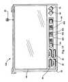
- FIG. 2is an enlarged perspective view of the master presentation unit of FIG. 1 ;
- FIG. 3is a schematic partial cross sectional view of the master unit of FIG. 2 ;
- FIG. 4is a perspective view of one of the slave units of FIG. 1 ;
- FIG. 5is a schematic partial cross sectional view of the slave presentation unit of FIG. 4 ;
- FIG. 6is a perspective view of a second embodiment of a slave unit that may be used with the master unit of FIG. 1 ;
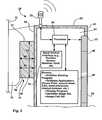
- FIG. 7is a view similar to the view of FIG. 5 , albeit illustrating another exemplary slave presentation unit design
- FIG. 8is a similar to FIG. 7 albeit illustrating one additional slave presentation unit
- FIG. 9is similar to FIG. 7 albeit illustrating yet one more slave presentation unit embodiment
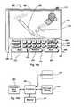
- FIG. 10 ais a perspective view of a handheld interface unit shown in FIG. 1 ;
- FIG. 10 bis a schematic view of components that make up one embodiment of the interface unit of FIG. 10 a;
- FIG. 11is similar to FIG. 1 , albeit illustrating a system that includes a different type of slave presentation unit
- FIG. 12is similar to FIG. 1 , albeit illustrating slave presentation units that include flat panel displays;
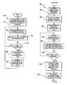
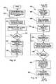
- FIG. 13is a flowchart illustrating a flipping method according to one aspect of the present invention that may be used with any one of the systems shown in FIGS. 1 through 12 ;
- FIG. 14is a sub-process that may be substituted for a portion of the method illustrated in FIG. 13 for retrieving images from a slave unit and re-presenting the images via the master unit;
- FIG. 15is a method for flipping images from a master unit to a slave unit and thereafter retrieving an image from a slave unit where the slave unit is uniquely identifiable;
- FIG. 16is a flowchart illustrating a method whereby images currently displayed via a master presentation unit and slave presentation units may be quickly stored and subsequently re-accessed and re-presented via the same units on which the images were presented prior to being saved;
- FIG. 17is similar to FIG. 2 , albeit illustrating a master unit that includes a different compliment of control buttons;
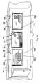
- FIG. 18is a plan view of a system consistent with certain aspects of the present invention including a single presentation unit that divides surface space into a plurality of presentation surfaces that can be used to mimic flip chart activity;
- FIG. 19is similar to FIG. 18 , albeit illustrating a different system wherein presented images are managed in a different manner;
- FIG. 20is a perspective view of another inventive embodiment including three projectors and associated projection screens/assemblies;
- FIG. 21illustrates yet another embodiment where a master unit is in the form of an easel assembly and slave units are wall mounted
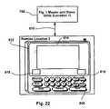
- FIG. 22is a schematic illustrating a system where an interface unit is used to remotely control a presentation using remotely located master and slave units.
- FIG. 1While the system components to be described may be used in any space to present information to an audience and/or to facilitate collaborative activity between a system operator and an audience, in order to simplify this explanation, the systems and components will be described in the context of an exemplary conference room 11 including a presentation wall 12 generally located at a front end of the conference room 11 , a door 14 for entering and exiting the conference room 11 and a plurality of conference tables or desks, two of which are identified by numerals 16 and 18 , respectively.
- the tables 16 and 18are arranged as are seats (not illustrated) within room 11 so as to orient audience members within room 11 to easily observe information presented to the audience at the front of room 11 adjacent wall 12 .
- an elongated horizontal rail 40is mounted to wall 12 at approximately 6 to 7 feet above the floor within room 11 for either temporarily or permanently supporting master and slave presentation units adjacent wall 12 .
- rail 40has a height dimension H 1 and a width W 1 that are perpendicular to the length of rail 40 and forms a horizontal top surface 41 .
- Rail 40may be mounted to wall 12 in any secure manner including bolts or the like and is held off the surface of wall 12 such that distal ends (e.g., 74 in FIG. 3 ) of presentation unit mounting members to be described in greater detail below fit between the wall and a rear surface of rail 40 .
- an exemplary first system 10includes a master presentation unit 28 and first and second slave presentation units 22 a and 22 b , respectively. As illustrated in FIG. 1 , each of the presentation units 28 , 22 a , 22 b , etc., are mounted to and hang from rail 40 adjacent wall 12 so that front presentation surfaces (generally identified by numeral 48 or numeral 48 followed by a lower case letter) are easily observable by an audience within room 11 . Referring also to FIGS.
- master presentation unit 28is an electronic image-forming device which, in the illustrated embodiment, includes a flat plasma or liquid crystal type display screen 48 mounted within a rigid generally rectilinear and relatively thin plastic or metal housing assembly 52 , a transceiver 20 and first and second mounting hooks or members 72 , 74 , respectively.
- housing 52includes oppositely facing front and rear surfaces 53 and 55 , respectively.
- Front surface 53forms an opening 57 in which screen 48 is mounted so that a front surface 54 thereof having a width dimension W 2 and a height dimension H 2 is observable.
- Mounting members 72 and 74extend from opposite lateral upper corners of rear surface 55 and extend downwardly at distal ends thereof so as to form channels 17 and 19 between rear surface 55 and facing surfaces of the distal ends (one of the facing surfaces identified by numeral 59 in FIG. 3 ).
- Each channel 17 , 19has a recess dimension R 1 which is substantially similar to width dimension W 1 of rail 40 (see FIG. 3 ).
- unit 28To mount master unit 28 to rail 40 , as best illustrated in FIGS. 1 and 3 , unit 28 is lifted and positioned with respect to rail 40 such that the channels formed by members 72 and 74 are above rail 40 . Thereafter, unit 28 is lowered until sections of rail 40 are received within the channels formed by members 72 and 74 and so that members 72 and 74 are generally supported on the top rail surface 41 (see FIG. 3 ).
- one or more additional extension membermay be provided that extends from rear surface 55 proximate the bottom end thereof to contact the wall 12 surface and stabilize unit 28 in a substantially vertical orientation.
- exemplary master presentation unit 28includes a processor 80 , a keyboard or other type of control interface 30 (i.e., the keyboard is not necessary where interactivity is provided via other means such as selectable on-screen icons, etc.) and a digital memory 88 .
- Processor 80 and memory 88are mounted within cavity 61 formed by housing 52 while keyboard 30 includes keys supported by the housing structure.
- Processor 80is linked to each of transceiver 20 , display screen 48 , keyboard 30 and memory 88 via a plurality of data busses (not labeled).
- transceiver 20is capable of transmitting and receiving information via any of several different wireless technologies (e.g., RF, infrared, etc.) and via any of several different wireless communication protocols (e.g., 802.11b, Bluetooth, etc.) within the vicinity of transceiver 20 (e.g., within the space defined by a conference room 11 ).
- wireless technologiese.g., RF, infrared, etc.
- wireless communication protocolse.g., 802.11b, Bluetooth, etc.
- Memory 88is a digital memory device and includes a plurality of different types of information usable by processor 80 to perform various methods. Generally, the information stored in memory 88 takes two forms including programs run by processor 80 and data such as images presented via display screen 48 . Programs run by processor 80 include, in at least some cases, position sensing programs for sensing the position of virtual ink pens and virtual ink type eraser devices used to add information to and delete information from screen 48 as well as display driver programs for presenting information via display 48 .
- memory 88includes programs used to manage images present via display 48 .
- a program in memory 88may assign unique identifier numbers or the like to each image flipped from unit 28 to one of the slave presentation units and may store each flipped image and corresponding identifier number within memory 88 for subsequent access.
- the master unit processor 80may be programmed to correlate and store the flipped image with a unit identifier that uniquely identifies the slave unit to which the image is being flipped. After an identifier and an image is stored in memory 88 , the image may be accessed via reference to the unique identifier.
- copies of conventional software applicationssuch as PowerPoint, various spread sheet applications, CAD applications, word processor applications, internet browser applications, etc.
- conventional software applicationsmay not be useable with system 10 and in that case, copies of the conventional software applications would not be stored in memory 88 .
- software applicationssuch as PowerPoint, spreadsheets and the like may be stored in or accessed via a palm or laptop type computer useable with master presentation unit 28 so that, while processor 80 is used to display images corresponding to conventional software applications, processor 80 itself does not run the software applications.
- the computerwould run the programs and provide information to processor 80 to drive the display 48 .
- control interface 30may include various types of input devices.
- mechanical hardware type buttonslike the keys illustrated in FIG. 2 may be provided within the front surface 53 of housing 52 for providing commands to processor 80 such as flip commands (i.e., commands that indicate that an image currently on display 48 should be transmitted to slave presentation units and then removed from display 48 ) and other data access and program control commands.
- touch selectable iconsmay be provided on display screen 48 for selection by a system operator which, when selected, provide command signals to processor 80 to perform processes.
- the input device 30may include image augmentation capabilities (i.e., be in part an augment interface) so that marks can be added to an image on screen 48 or deleted.
- image augmentation capabilitiesi.e., be in part an augment interface
- input to master unit 28may always be via a palm or laptop type computing device (e.g., a portable control interface) where commands to processor 80 are received via transceiver 20 .
- the master unit 28includes a mechanical type keyboard 30 .
- palm and laptop computers and control deviceswill be referred to generally as hand held devices (HHDs).
- unit and device communicationmay be wired, it will be assumed here that all unit and device communication is via a wireless protocol and transceivers (e.g., 20 in FIG. 2 ).
- exemplary master unit keyboard keysinclude a resume key 56 , a send key 58 , a store key 60 , a retrieve key 62 , a left send key 68 , a right send key 70 , and a number pad 67 .
- the selectable keys described and illustrated hereinare only exemplary and, in many cases, additional selectable keys or a subset of the keys described herein may be provided via display 48 , the selectable key set being dependent upon the functions supported by the system 10 and, in at least some cases, the relative juxtaposition of system components.
- mouse or touch selectable icons required to support the software applicationsmay appear on display 48 .
- master presentation unit 28may be positioned to one side of the slave presentation units 22 a , 22 b , etc. relative to an audience viewing the units within room 11 .
- to flip an image from display 48 to one of the slave presentation units 22 a , 22 b , etc.there must be some way to specifically identify the slave unit to receive the flipped image.
- unique slave unit identifiers “1” and “2”are provided on each one of the slave units 22 a , 22 b , etc., which are easily viewable by a system operator when the operator is in a position to facilitate collaborative activity by interacting with master unit 28 .
- the unit identifiers “1” and “2”are permanently printed at one end of each of the unit housing assemblies.
- processor 80is programmed to monitor keyboard 30 for an indication that the image on display 48 is to be flipped to one of units 22 a or 22 b .
- processor 80uses number 67 to select the unit identifier number corresponding to the unit to which the image is to be flipped and subsequently selects send key 58 .
- the operatoruses pad 67 to select number “1” and then selects key 58 .
- the operatorselects number “2” from pad 67 and subsequently selects send key 58 .
- each separately addressable slave units and also, in some embodiments, master unit 28has a unique network address that can be used to send data thereto.
- slave units 22 a and 22 bmay be assigned unique wireless addresses “XP45519784” and “QZ1433217”, respectively, while master unit 28 is assigned address “AM7966142”.
- the addresses of slave screensare correlated with the unique salve unit identifiers (e.g., “1” and “2” in the present example) and the correlated addresses and identifiers are stored in master unit memory 88 .
- processors in each of the slave units 22 a , 22 b , etc.are programmed to monitor for and receive wireless signals sent to their respective network addresses.
- processor 80identifies the network address associated with the target slave unit, generates an image data packet including the image and the address of the target slave unit, transmits the data packet to the selected slave unit and then, in at best some embodiments, erases the image from display 48 (i.e., blanks display 48 ) or otherwise renders the image un-observable via display 48 to provide a clean and clear surface 48 in a manner that mimics a conventional paper pad type flip chart.
- a second affirmative stepmay be required to render the master image un-observable.
- master presentation unit 28is also useable to retrieve images presented via the slave presentation units 22 a , 22 b , etc., so that those images can be edited and then re-presented via the slave units in the edited form.
- the image data received by the slave unitis temporarily stored in a slave unit memory (see 119 in FIG. 5 ).
- a system operatorwants to edit that image, in a manner similar to the manner described above for flipping an image to unit 22 b , the system operator uses number pad 67 to select the identifier number corresponding to the slave unit and then selects retrieve key 62 .
- retrieve key 62When retrieve key 62 is selected, master processor 80 forms a retrieve data packet including an image retrieve request and the address of the slave unit from which to retrieve the image and wirelessly transmits the retrieve data packet to the slave unit.
- the slave unitgenerates an image data packet including the slave image and the network address of the master unit and transmits the image data packet back to the master unit 28 .
- master unit 28re-presents the image via display 48 for further collaborative viewing/editing.
- the imagewhen master unit 28 flips an image to a slave unit, the image may be correlated with and stored with the unique slave unit identifier in master unit memory 88 . Thereafter, when an operator wants to re-present a slave image via master unit 28 for editing or the like, the operator can select the appropriate slave unit identifier (i.e., the identifier number associated with the slave unit presenting the image to be re-accessed) via number pad 67 followed by retrieve key 62 causing processor 80 to access the previously stored image in memory 88 and present the image via display 48 .
- the appropriate slave unit identifieri.e., the identifier number associated with the slave unit presenting the image to be re-accessed
- a functionis provided whereby the operator can quickly store all of the images currently presented via the presentation units such that, upon resuming the presentation or collaborative activity, all of the currently presented images can be quickly and immediately re-presented via the presentation units in the same relative juxtapositions.
- processor 80may be programmed to monitor store key 60 and, when icon 60 is selected, may correlate each of the unique presentation unit identifiers (e.g., “1”, “2”, etc., an identifier uniquely associated with master unit 28 , etc.) with the image currently displayed by the corresponding presentation unit as an image-unit set and then to store the image-unit set in memory 88 . Thereafter, to re-present the images via the master and slave units at a subsequent time, the operator may select resume key 56 after which processor 80 accesses the image-unit set and re-presents those images via the master and slave units.
- the unique presentation unit identifierse.g., “1”, “2”, etc., an identifier uniquely associated with master unit 28 , etc.
- processor 80may be programmed to enable the operator to uniquely identify the image-unit set by providing a name therefore useable to recognize the specific image-unit set.
- more than one image-unit setmay be stored in memory 88 and subsequently unambiguously retrieved to resume presentations.
- processor 80simply accesses the stored images and addresses and flips the images to the correlated addresses without having to perform the intermediate step of correlating the unit identifiers and addresses.
- the number of slave units used with a master unitwill not change and that keys dedicated to specific slave units and functions may be provided on keyboard 30 .
- a system 10only includes one master unit 28 and two slave units 22 a and 22 b
- separate send and retrieve keys for each of the slave units 22 a and 22 bmay be provided so that single key selection can cause image flipping/retrieving.
- a master unit 28may be positioned between two slave units (i.e., master unit 28 and slave unit 22 a would be swapped so that unit 28 is between slave units 22 a and 22 b ).
- simple left and right send icons 68 and 70may be used to flip images from master unit 28 to the slave units to the left and right of the master unit, respectively.
- simple left and right retrieve arrow icons similar to icons 68 and 70may also be provided for retrieving images from the slave units to be re-presented via screen 48 .
- each of the slave presentation units 22 a and 22 bwill have a similar construction and similar operation and therefore, in the interest of simplifying the present explanation, only unit 22 a will be described here in detail. Referring also to FIGS.
- slave presentation unit 22 ais a pull-out, roller window shade style unit and includes a housing assembly 100 (hereinafter housing 100 ), a transceiver 34 a , a rollable and unrollable presentation screen 38 a , first and second mounting members or hooks 102 and 104 , respectively, a processor 110 , a motor 112 , a powered screen spindle 114 , a slave presenter/print applicator that takes the form of a printer 116 in the present example, an eraser 118 and a memory 119 .
- Housing 100is generally a rigid box shaped assembly that forms a cavity 105 between top and bottom walls 107 and 109 , respectively, and front and rear walls 111 and 113 , respectively.
- the front wall 111 and rear wall 113form opposite facing front and rear surfaces 101 and 103 , respectively.
- Bottom wall 109forms a slit or opening 122 generally along the length of housing 100 through which a lower end of screen 38 a extends.
- Each of mounting members 102 and 104like mounting members 72 and 74 that are secured to master unit housing 52 , are secured to an extend rearwardly from the rear surface 113 of housing 100 and extend from opposite ends of housing 100 .
- the distal ends of each of members 102 and 104extend downwardly such that member 102 forms a channel 117 and member 104 forms a channel 115 having a channel dimension R 2 which is similar to the width dimension W 1 of rail 40 .
- slave unit 22 ais mountable to rail 40 by placing members 102 and 104 over rail 40 so that rail 40 is received within channels 115 and 117 .
- Transceiver 34 ais mounted to top wall 107 and extends upwardly therefrom.
- Screen 38 ain at least some embodiments of the present invention, is a flexible and rollable generally rectilinear member that, when unrolled, extends through opening 122 and there below to provide a presentation surface 48 a that faces in the same direction as front surface 101 of housing 100 .
- presentation surface 48 ais a writable/erasable surface such as Mylar (trademarked name of a polyester material developed and sold by DuPont) or the like on which erasable ink can be printed or plotted and can subsequently be erased.
- a weighted bar 106may be mounted to a distal lower end of screen 38 a that helps to maintain screen 38 a substantially flat when screen 38 a is unrolled and extends below housing 100 .
- each of processor 110 , motor 112 , spindle 114 , printer 116 and eraser 118is mounted within housing cavity 105 .
- Processor 110is linked to each of motor 112 , printer 116 and eraser 118 for controlling each of those components.
- Processor 110is also linked to memory 119 for accessing information therein and is linked to transceiver 34 a to send and receive data packets.
- Motor 112is linked to spindle 114 for rolling and unrolling slave screen 38 a which is attached at a top end to spindle 114 .
- Processor 110controls printer 116 to, when an image is flipped to slave unit 22 a from master unit 28 , print the image on presentation surface 48 a either as screen 38 a is being unrolled or, in the alternative, by moving one or more printer heads adjacent to the surface 48 a while moving screen 38 a up and down via spindle. In any event, processor 110 controls printer 116 to provide a rendition of the image flipped to unit 22 a from master unit 28 . In some cases the rendition will be in color while in other cases it may be in black and white. In still other cases the user may have the option to print in color or in black and white.
- Eraser 118is controlled by processor 110 to erase ink applied by printer 116 to presentation surface 48 a .
- eraser 118may simply move back and forth along the length of housing 100 while holding an eraser pad on surface 48 a as screen spindle 114 rolls up screen 38 a .
- processor 110may be able to control eraser 118 to erase certain information from surface 48 a while leaving other information on surface 48 a .
- the modified imagemay be presented via unit 22 a by erasing the appropriate information from surface 48 a and unrolling screen 38 a so that the modified image is viewable via surface 48 a.
- the image data packetis transmitted via transceiver 22 to processor 110 via transceiver 34 a after which processor 110 controls motor 112 and printer 116 to simultaneously unroll screen 38 a and apply ink to surface 48 a thereby forming the flipped image on surface 48 a .
- processor 110first controls motor 112 and eraser 118 to roll up screen 38 a while simultaneously erasing the ink printed thereon.
- processor 110next controls motor 112 and printer 116 to again apply ink to surface 48 a thereby providing the newly flipped image on surface 48 a for the audience to view.
- the dimensions of the master display screen 48 and the portion of the slave screen 38 a that is unrolled and used to present an imageare similar such that an image flipped to and presented via screen 38 a has a scale substantially similar to the scale of the image that was originally presented via display 48 .
- the entire system described abovecan be easily transported from one conference room 11 to another and can easily be set up by placing the mounting members that extend from the rear surfaces of the units over a rail in the other conference room similar to rail 40 .
- the screens (e.g., 38 a ) of the slave unitscan be completely rolled up for protection and to provide a compact configuration.
- a second embodiment of a slave presentation unit 120including a top header 122 , a housing 124 , a transceiver 130 , a screen 126 and first and second mounting members 132 and 134 , respectively.
- Mounting members 132 and 134are similar in construction and operation to mounting members 102 and 104 described above and therefore will not be described here in detail.
- members 132 and 134extend from a rear surface of header 122 for mounting unit 120 to a rail like rail 40 described above.
- screen 126is rigidly secured to a lower surface of header 122 and lower housing 124 forms an opening (not illustrated) through which a distal lower end of screen 126 extends and in which a screen spindle similar to spindle 114 described above with respect to FIG. 5 is mounted.
- the processor 110 , motor 112 , printer 116 , memory 119 and eraser 118 described above with respect to FIG. 5are also mounted within housing 124 and transceiver 130 extends upwardly from housing 124 .
- the image data packet transmittedis received via transceiver 130 and the processor in housing 124 simultaneously controls the motor and printer therein to unroll screen 126 and apply ink to surface 126 forming the flipped image thereon as housing 124 descends (see arrow 128 ) below header 122 .
- An advantage hereis that the image can be printed from top to bottom.
- the processor inside housing 124simultaneously controls the motor and eraser in housing 124 to roll screen 126 up and erase ink from surface 126 .
- each of the slave unitsincludes a processor 110 , a motor or motivator of some type 112 , a printer 118 , an eraser 116 , a memory (not illustrated), mounting members (e.g., 104 ) and a transceiver 34 a similar to those described above with respect to FIG. 5 and therefore, in the interest of simplifying this explanation, those components are not separately described again here.
- the primary difference between the embodiments of FIGS. 7 , 8 and 9 and the embodiment of FIG. 5is in how the presentation screens are extended and retracted.
- FIG. 7is generally a pull-out endless loop style unit and includes both a powered spindle 151 and a freewheeling spindle 148 .
- Powered spindle 151is driven by motor 112 under the control of processor 110 .
- screen 144is a continuous belt or loop type screen that wraps around powered spindle 151 within housing 100 and extends downward and wraps around freewheeling spindle 148 below housing 100 such that a front screen segment forms a front presentation surface 155 and a rear screen segment forms a rear surface 159 facing in a direction opposite the direction of surface 155 .
- housing 100forms two slit like openings 140 and 142 that extend generally along the entire length of housing 100 to allow screen 145 to pass therethrough.
- spindle 151may be powered in either clockwise or counterclockwise direction so that screen 144 can move in either direction up or down as indicated by arrow 146 and so that freewheeling spindle 148 can rotate in either clockwise or counterclockwise directions as indicated by arrow 150 .
- processor 110controls the motor 112 and printer 116 simultaneously to apply ink and form the image on screen 144 as spindle 151 rotates in the clockwise direction. After an image is formed, the image is viewable on front surface 155 between housing 100 and freewheeling spindle 148 .
- spindle 151may be rotated in the counterclockwise direction while eraser 118 removes the ink from screen 144 .
- spindle 151may be rotated in the clockwise direction so that the image rotates about freewheeling spindle 148 , back up toward and around powered spindle 151 and again down past eraser 118 while eraser 118 erases the ink on the screen.
- eraser 118may be positioned on the opposite side of screen 144 within housing 100 and may be used to erase images presented thereto on screen 144 as section 155 is moved up through opening 140 .
- exemplary slave presentation unit 173is a pull-out drop loop style unit and includes a first powered spindle 163 and a second powered spindle 165 , both mounted within housing 100 , as well as a freewheeling spindle 167 wherein first and second ends of a presentation screen 181 are mounted to and rolled around spindles 163 and 165 , respectively, and a central portion of screen 181 wraps around freewheeling spindle 167 that hangs below housing 100 .
- the powered spindles 163 and 165may be used to move a presentation surface 183 of screen 181 either upward or downward as indicated by arrow 146 and about spindle 167 in either direction as indicated by arrow 187 .
- a printer 116 and an eraser 118may be controlled to apply ink to the presentation surface or to remove ink therefrom to reflect image flipping activity caused by interaction with master unit 28 .
- unit 175is a pull-out accordion style unit similar to the units described above with respect to FIGS. 5 , 7 and 8 except that the spindles are replaced by a take up and let down assembly 174 and the screen, instead of being a rollable screen member, is a segmented accordion type screen 172 including elongated horizontal screen members, two of which are collectively identified by number 189 , that are linked along horizontal elongated edges.
- motivator 112is controlled by processor 110 to let out the screen 172 adjacent printer 116 and to take up the screen 172 adjacent eraser 118 as indicated by arrow 170 .
- an exemplary HHD interface unit 200includes a generally rectilinear and rigid plastic or metallic housing 199 that protects and supports other unit components including a processor 203 , a display 204 , a keyboard 209 and a transceiver 211 .
- Processor 203is linked to each of transceiver 211 , screen 204 , memory 207 and keyboard 209 to receive information therefrom or provide information thereto, where appropriate.
- Processor 203runs various programs stored in memory 207 .
- processor 203may be able to access a conventional computer network (e.g., a local area network, a wide area network, the Internet, etc.) via wireless communication with access points mounted within or proximate conference room 11 .
- a conventional computer networke.g., a local area network, a wide area network, the Internet, etc.
- access pointsmounted within or proximate conference room 11 .
- Communication between wireless devices like unit 200 and a network server via access pointsis well known in the wireless communication arts and therefore, in the interest of simplifying this explanation, will not be described here in detail.
- Keyboard 209includes hardware keys that are akin to the keyboard keys described above with respect to FIG. 2 .
- mechanical keys 208 , 210 , 216 and 220are akin to keys 56 , 60 , 62 and 58 described above and can be used to resume a presentation, store images associated with a presentation, retrieve images presented by slave units so they can be re-presented by the master unit 28 and to send images from the master unit 28 to any one of the slave units, respectively.
- Number pad 214is used in a manner similar to the number pad 67 described above with respect to FIG. 2 . For instance, to indicate a slave unit associated with identifier number “2” to which an image should be flipped, an operator selects the “2” key from keyboard 209 followed by the send key 220 .
- Left arrow key 222is a send left key indicating, as its label implies, that an image currently presented via master unit 28 should be sent to a slave unit to the left of master unit 28 .
- right arrow key 228is a send right key indicating that an image currently displayed by the master unit 28 should be sent to the slave unit to the right of the master unit 28 .
- Right directed arrow key 223is a left retrieve key indicating that the image currently presented on a slave unit to the left of master unit 28 should be retrieved to the master unit and displayed thereby.
- left directed arrow key 226is a right retrieve key indicating that an image currently presented by a slave unit to the right of master unit 28 should be retrieved and displayed via master unit 28 .
- an enter key 212is provided via unit 200 which can be used to indicate that information entered via other keyboard keys should be acted upon. For example, in cases where a presentation is to be resumed and a specific seven digit number code must be entered to access a specific previously stored image-unit set, after resume button 208 is selected, processor 203 may present a session identification number field via display 204 in which a specific sequence of seven numbers has to be entered in order to access the images corresponding to an image-unit set and present the images via the presentation units.
- unit 200may include a full keyboard compliment including letters, numbers and function keys that are typically found on a computer keyboard so that unit 200 can, in effect, be used as a complete laptop computer to interact with various software applications (e.g., Power Point, spreadsheet applications, word processor applications, etc.).
- software applicationse.g., Power Point, spreadsheet applications, word processor applications, etc.
- screen 204is a fully functional touch sensitive flat panel display screen which can be used to display virtually any type of visual image including images corresponding to software applications, images corresponding to information applied to screen 204 via a stylus 202 or other similar types of interface tools and, in at least some cases, images that combine software generated images and applied information.
- a system operatormay use stylus 202 to make a mark (e.g., 229 in FIG. 10 a ) on display 204 which is tracked by processor 203 and in response to which processor 203 changes the image on display 204 so that the mark is represented.
- the markis referred to as a virtual ink mark because the mark appears on display 204 despite the fact that no real ink is applied to the surface of screen 204 .
- the information presented via display 204 of control interface 200is immediately updated on the master display 48 of unit 28 .
- the operatorcan use HHD 200 to modify the image displayed on display 48 in a real time and collaborative flip chart like manner.
- the operatoruses HHD 200 to flip the image to the appropriate slave unit. For instance, in the example illustrated in FIG. 1 , to flip an image from master unit 28 to slave unit 22 a , the operator selects the “1” key on HHD 200 followed by send key 220 .
- processor 203After send key 220 is selected, processor 203 forms a flip command data packet commanding an image flip to the selected slave unit and including the master unit network address and transmits the flip command data packet to processor 80 (see again FIG. 3 ) via transceivers 211 and 20 . In response to receiving the flip command, processor 80 forms an image data packet including the currently displayed image and transmits the image data packet to the slave unit selected via HHD 200 .
- unit 200may be a stand alone laptop computer and may provide the complete data processing platform where master unit 28 is simply an output and input device.
- programs to track interactivity with display 20may be run by unit 200 and unit 200 may simply provide display driving data to the master unit processor 80 .
- the unit 200may completely organize the image presentation and master unit 28 may not perform the flipping and retrieving processes.
- unit 200may store all of the images including the images displayed by the master and slave units.
- the commandmay be received by unit 200 which in turn causes the flip to occur via transmission of the master image to the designated slave unit.
- unit 200may also automatically transmit a command to the master unit to erase the flipped image. Retrieval commands would also be performed via unit 200 as opposed to via the master processor 80 .
- System 230is shown in the context of a conference room like conference room 11 described above with respect to FIG. 1 where presentation units 48 and 232 are mounted on a rail 40 within the room for easy viewing of associated presentation surfaces by an audience.
- master unit 28is similar to the master unit 28 described above with respect to FIG. 1 with few differences.
- master unit processor 80 in the FIG. 11 embodimentis programmed slightly differently than the processor described above with respect to FIG. 1 . More specifically, because there is only one slave unit 232 in system 230 , processor 80 is programmed to flip all images to single slave unit 232 when send commands are received.
- processor 80is programmed to add an image identifier number to the flipped image which, in the example here, is added to the flipped image in the upper left hand corner.
- image identifier numbers “6” and “7”are associated with images presented on surfaces 250 and 248 , respectively, and therefore, identifier numbers 6 and 7 have been added to each of the images so that each image can be subsequently uniquely identified.
- processor 80prior to flipping an image to slave unit 232 , processor 80 correlates and stores the image and the image identifier number in master unit memory 88 for subsequent access.
- master unit processor 80(see again FIG. 3 ) stores the image on surface 250 with identifier number 6 and similarly stores the image on surface 248 with identifier number 7 when each of those images is flipped to slave unit 232 .
- slave presentation unit 232is a large format printer or plotter that includes a subset of the components or a set of components akin to the components illustrated in FIG. 5 .
- unit 232includes a processor 336 , a motor 338 , a printer 340 and a large roll of paper 342 as well as a transceiver 240 .
- processor 336is linked to motor 338 , transceiver 240 and printer 340 and, when an image is flipped to unit 232 , processor 336 controls motor 338 and printer 340 simultaneously to unroll a portion of the paper roll while applying ink to a front surface 250 thereof as the unrolled portion of the roll drops downward.
- printer 340applies the image identifier number (e.g., “6” in FIG. 11 ) in the upper left hand corner of the image.
- rail 40may include a corkboard front surface so that tacks can be used to post torn sheets there along.
- an exemplary torn sheet 234 having the number “7” as an identifier numberis illustrated as being posted to rail 40 adjacent unit 232 . It is contemplated that perforated lines may be provided at spaced locations along the length of the paper roll so that sheets can be torn off in a clean fashion.
- a system operatoruses number pad 67 to select the number associated with the image to re-present and then selects retrieve key 62 . For instance, to re-present the image on sheet 234 in FIG. 11 , the operator selects number “7” and retrieve key 62 . After key 62 is selected, referring once again to FIG. 3 , master unit processor 80 accesses the image stored in memory 88 corresponding to image identifier number “7” and re-presents that image via display 48 . Once the image is re-presented, the image may be modified and then re-flipped to slave unit 232 for printing and posting.
- the system 251includes a master presentation unit 48 and first and second slave units 252 a and 252 b , respectively.
- master unit 48is mounted to a rail 40 between slave units 252 a and 252 b so that, when viewed from an audience's perspective, unit 252 a is to the left of master unit 48 and unit 252 b is to the right of master unit 48 .
- Master unit 48is similar to the master units described above and therefore will not be described here in detail.
- Each of slave units 252 a and 252 bis similarly constructed and operates in a similar fashion and therefore, in the interest of simplifying this explanation, only unit 252 a will be described in any detail.
- Unit 252 aincludes a hardened, generally rectilinear, plastic or metallic housing 258 a , a transceiver 254 a and a large format thin profile plasma, LCD or other thin profile display screen 256 a .
- unit 252 aalso includes a processor and a memory linked thereto, neither of the processor nor memory illustrated. The slave processor is linked to display 256 a and to slave transceiver 254 a as well as to the slave memory.
- the imagewhen an image is flipped from unit 48 to slave unit 252 a , the image is transmitted wirelessly to unit 252 a and is immediately presented via display 256 a .
- unit 28is immediately blanked so as to mimic the flipping of a sheet on a conventional paper pad type flipchart.
- the image and the slave unit to which the image has been flippedmay be correlated and stored in either the master unit memory 88 or in the slave unit memory.
- the keyboard on unit 28may be used to identify the slave unit from which the image is to be retrieved and then to perform the retrieval process.
- the retrieval processmay be completely internal to unit 28 where the image presented by the slave unit is stored in master unit memory 88 .
- the retrieval processmay require a retrieval request packet from master unit 28 to the slave unit (e.g., 252 a in FIG. 12 ) to retrieve the image and then a second packet transmission from the slave unit back to master unit 28 .
- System 470includes a single presentation unit (also referred to by numeral 470 ) that includes a display 474 mounted within a rigid housing assembly 472 so that a display surface 475 is observable to the audience.
- surface 475is generally divided into a plurality of sub-spaces for presentation purposes including adjacent spaces 476 , 478 and 480 .
- system 470may include a front projector unit (not illustrated) that projects images into each of presentation surface spaces 476 , 478 and 480 .
- unit 470may be a flat panel plasma, LCD type display or other thin type display where separate images are presented via each of spaces 476 , 478 and 480 .
- Icon 484is selectable to indicate that an image presented via surface 478 should be flipped left to surface 476 as indicated by arrow 490 .
- Arrow icon 486is selectable to indicate that an image presented via surface 478 should be flipped right to surface 480 as indicated by arrow 492 .
- arrow icon 482is selectable to indicate that the image on left surface 476 should be retrieved and presented on surface 478 as indicated by arrow 494 and arrow icon 488 is selectable to indicate that an image on right surface 480 should be retrieved and presented on central surface 478 as indicated via arrow 496 .
- the central presentation surface 478may be useable in the same way that the master units described above are useable to edit images and to flip the images to slave units and retrieve the images from slave units.
- a system 520 similar to the system of FIG. 18includes a single presentation unit 522 that is an electronic, flat panel unit having a presentation screen 524 that forms a viewing surface 526 .
- a system operatore.g., via a stylus, the users finger, etc.
- a master presentation space 530may be represented on surface 526 in a visually distinct manner such as by placing a border or outline line therearound.
- master space 530is illustrated as being located generally on the central part of surface 526 .
- more elaborate visual graphicsmay be provided to distinguish master space 530 .
- space 530may be distinguished via graphics that resemble a flip chart.
- a control icon 536is provided within master space 530 that can be used to flip images from master space 530 to other spaces on surface 526 .
- a system operatorcan place the tip of a stylus in icon 536 to drag the image to another location on surface 526 .
- the imageis dragged from master space 530
- the master space and its visually distinguishing featureswill remain in their original positions on surface 526 .
- FIG. 19one image previously flipped or dragged from master space 530 is labeled 528 and a second image being flipped from space 530 as indicated via arrow 540 is labeled 532 .
- An arrow 542represents the tip of a stylus used by the operator to perform the dragging process.
- control iconswill move therewith so that the flipped images can be moved about surface 526 after flipping.
- images previously flippedmay be retrieved to master space 530 by selecting the control icon on the flipped image and dragging the selected icon back into master space 530 .
- software for master space editing and display of software screen shotsare contemplated.
- the master unitincludes a master display screen or assembly 554 and a master front projector unit 560 while the first and second slave units include slave screen 552 and first slave projector unit 558 and second slave screen 556 and second slave projector unit 562 , respectively.
- Screens 552 , 554 and 556include display projection surfaces 564 , 566 and 568 , respectively, that are all of similar dimensions and which would each be juxtaposed for simultaneous viewing by an audience or group participating in collaborative activities.
- master assembly 554includes a laser sensor unit 570 mounted along a top edge of screen 554 for sensing positions of styluses, pens, erasers, etc., on or proximate surface 566 .
- Master assembly 554is linked to (not illustrated) or includes a processor akin to the processors described above for controlling images and system software generally and, more specifically, for controlling image flipping activity as well as retrieval of images back to master surface 566 for viewing and editing.
- System 600includes a master presentation unit 610 and three slave units 604 , 606 and 608 .
- Each of the slave units 604 , 606 and 608is similar to the slave units described above with respect to FIGS. 1 , 4 and 5 and therefore are not described again here in detail.
- each slave unit 604 , 606 and 608is mounted to a wall 601 and more specifically via a wall mounted rail 602 and is capable of receiving images flipped thereto from master unit 610 and presenting received images via a slave presentation surface (i.e., surfaces 622 , 624 and 626 ).
- master unit 610is a portable floor supported easel type assembly including an easel structure (also identified via numeral 610 ) having an interior space 614 and one or more shelf members 616 .
- easel structurealso identified via numeral 610
- casters 618are mounted at the bottom end of easel structure 610 to facilitate movement within a facility.
- a computer projector and other system componentsmay be located on shelves 616 within space 614 .
- Unit 610includes a master presentation surface 612 for presenting master images, modifying the images and generally facilitating collaborative activity.
- on-screen selectable iconsmay be provided via surface 612 for flipping master images to the slave units, to retrieve images and to perform other image management functions.
- screen 612may take any of several forms including a plasma screen, a rear projection screen where a rear projector is located within space 614 , a front projection screen, etc.
- FIGS. 13 through 16various methods and sub-methods consist of with certain aspects of the present invention are described. Each of the methods described herein may be used with at least one and in some cases more than one or even all of the systems described above or variations thereof.
- a method 270 for flipping images from a master unit 28 to a slave unitis illustrated. Referring also to FIGS. 1-5 , method 270 will be described in the context of system 10 .
- a system operatorarranges the master unit and the slave presentation units or devices for viewing by an audience within room 11 .
- informationis presented via master display 48 .
- processor 80monitors input devices such as keyboard 30 , wireless control signals generated via HHD 200 , etc., for a command to flip an image currently presented via unit 28 to one of the slave presentation units 22 a and 22 b .
- controlloops back up the block 274 where the method described above is repeated.
- controlpasses to block 280 where master unit 48 transmits the master image as part of an image data packet to the selected slave unit.
- the selected slave unitpresents the received image in any of the manners described above.
- sub-method 284which may be used to replace blocks 280 and 282 in FIG. 13 is illustrated which correlates flipped images with image identifiers so that images can be subsequently re-accessed, re-presented and edited via master unit 28 .
- sub-process 284is to be used with systems that assign unique image identifiers to images generated by the slave units where the slave units then include (e.g., print) the image identifiers with the images when images are generated.
- sub-method 284will described in the context of system 230 of FIG. 11 .
- the master imageis correlated with a unique image identifier number (e.g., “6” or “7” as illustrated in FIG. 11 ).
- master processor 80stores the correlated image and image identifier number in master memory 88 .
- master unit 28transmits the master image to the selected slave unit.
- the selected slave unitpresents the transmitted image along with the image identifier number.
- slave unit 232generates the image on surface 250 and adds the image identifier number “6” in the upper left hand corner. At this point the image flip has been completed.
- master processor 80monitors for a retrieval request for an image associated with a specific identifier number. For example, where identifier number “7” has been appended to an image on sheet 234 as indicated in FIG. 11 , the system operator may request retrieval of the image on sheet 234 via entry of number “7” and selection of the retrieve key 62 (see again FIG. 2 ).
- slave unit 22 acan be uniquely identified by number “1” while unit 22 b can be identified by number “2”.
- a slave identifiere.g., 24 a , 24 b , etc.
- the slave identifieris associated in some fashion with the wireless network address corresponding to the identifier on the slave device.
- the associated slave identifiers and network addressesare stored in master unit memory 88 .
- the master unit 28 and the slave presentation units 22 a and 22 bare arranged within room 11 for viewing by an audience.
- an imageis presented and/or manipulated via master display 48 .
- master unit processor 80monitors for a flip command indicating that the currently displayed image should be flipped to one of the slave presentation units.
- controlpasses back up and through blocks 336 and 338 .
- controlpasses to block 342 where the master image is correlated with the slave identifier specified by the operator (i.e., the identity of the slave unit to which the image is to be flipped).
- master processor 80stores the correlated image and slave identifier number in memory 88 and at block 346 master processor 80 transmits the master image to the slave unit.
- the slave unitpresents the received image.
- master processor 80monitors for a retrieve request indicating a specific slave identifier associated with a slave unit from which an image should be retrieved.
- controlpasses back up to block 348 and the loop described above is repeated.
- controlpasses to block 354 where processor 80 accesses the image correlated with the slave identifier in master memory 88 .
- processor 80re-presents the correlated image via master display 48 .
- Method 360is a method for correlating currently presented images with specific presentation units when a session store command is received, storing the correlated images and unit identifiers for subsequent access and then, when a resume command is received, for re-presenting the images via the presentation units associated therewith when the session store command was received.
- FIG. 1assume that during a collaborative session first, second and third images are presented via units 22 a , 22 b and master unit 28 when the store key 60 is selected, respectively.
- the first, second and third imagesare correlated with unit identifiers associated with units 22 a , 22 b and 28 , respectively, the correlated data is stored in master memory 88 as an image set and then the presentation surfaces of units 22 a , 22 b and 28 are cleared. Subsequently, when an operator resumes the session corresponding to the stored image set, processor 28 flips the first and second images to slave units 22 a and 22 b , respectively, for presentation and presents the third image via display 48 so that the session can continue where the session left off.
- processor 80monitors for selection of store key 60 .
- controlpasses back up to block 362 .
- processor 28blanks master display 48 and transmits signals to each slave unit (e.g., 22 a , 22 b , etc.) causing each of the slave units to blank their respective presentation surfaces.
- each slave unite.g., 22 a , 22 b , etc.
- data corresponding to the images from the presentation surfacesis maintained in master memory 88 or a combination of master memory 88 and the slave memories (e.g., 119 in FIG. 5 ).
- processor 80requests a session identifier from the operator that can be subsequently used to access the session images. For instance, processor 80 may provide a session identifier field and a query prompting the operator to name the session image set via master display 48 . Where a text session identifier is preferred, processor 80 may also provide touch selectable icons comprising a full alphabetical keyboard via display 48 or, in the alternative, may be capable of recognizing hand writing within the session identifier field. Instead of requesting a session identifier at block 171 , processor 80 may simply assign a random access code to the session image set and temporarily provide the code to the operator via display 48 .
- processor 80correlates each image in the image set with a unique presentation unit identifier (i.e., an identifier that is unique to one of master unit 28 or one of the slave units (e.g., 22 a , 22 b , etc.).
- master processor 80stores the session image set with the session identifier where each of the images is associated with a specific one of the master unit and the slave unit identifiers in master memory 88 . After block 370 all of the session images have been stored in an accessible format for future reference.
- master processor 80monitors for selection of resume icon 56 indicating that a previous collaborative session is to be resumed and therefore that a stored image set should be reaccessed and presented.
- controlpasses back up to block 374 . Once a resume command is received at block 376 , control passes to block 377 .
- master processor 80provides a request prompting a system operator to provide a session identifier corresponding to a previously stored image set.
- the promptmay include a text query and a session identifier field along with a suitable set of touch sensitive icons (e.g., numbers, alphanumeric, etc.) for specifying an identifier.
- the image set associated with an entered session identifieris retrieved from memory 88 and at block 380 the images in the set are displayed via the master display and the slave units so that the previous session can continue where it left off.
- controlpasses back up to block 362 where the process described above continues.
- master processor 80may be programmed such that, when store key 60 is selected once, the image currently presented via display 48 is stored and, when key 60 is selected twice in rapid succession (e.g., an action akin to a double-click of a mouse), processor 80 is programmed to store an entire compliment of session images as an image set.
- processor 80may perform a process similar to the one described above with respect to storage of session image sets, requiring a specific text or numeric image identifier from the system operator that can be used to subsequently reaccess the image.
- processor 80may provide a menu of options indicating the possible sources from which an image can be retrieved and suitable tools for accessing those images.
- a master presentation unit 528 similar to the master unit 28 of FIG. 2is illustrated where the master unit 528 provides a set of touch sensitive icons in a lower margin area 530 .
- the resume icon 56 , send icon 58 , store icon 60 and retrieve icon 62 as well as the left and right flip icons 68 and 70 , respectivelyhave functions that mirror the functions described above with respect to the similarly numbered keys in FIG. 2 and therefore, in the interest of simplifying this explanation, will not be described again here in detail.
- the main difference between the icon set provided via unit 528 and the key set provided via unit 28is that the number pad 67 in FIG. 2 has been replaced by a thumb nail sketch bar 450 in FIG. 17 .
- thumb nail of the flipped imagewill be presented via bar 450 .
- two exemplary thumb nail sketchesare identified by numerals 452 and 454 .
- the system operatorcan simply select one of the thumb nail sketches (e.g., 452 , 454 , etc.) and retrieve icons 62 to re-present the image via display 48 .
- all images flipped from master unit 528 to any of the slave unitsare stored and maintained within the master memory 88 until a system operator terminates a collaborative session and corresponding thumb nail sketches (e.g., 452 , 454 , etc.) are added to bar 450 .
- thumb nail sketchese.g., 452 , 454 , etc.
- Icons 64 and 66are left and right scrolling icons that enable the operator to graphically search a large number of thumbnail sketches for specific images to re-present.
- all flipped images and all stored images that are not flippedwill be stored in master memory 88 and represented as selectable thumbnail sketches in bar 450 .
- master unit 28may simply be a conventional whiteboard equipped with a camera wherein, when an image is flipped from the master unit to one of the slave units, the camera takes a picture of the image presented via the master unit and transmits that image to a selected slave unit for presentation.
- presentation units described hereininclude mounting members that mount the presentation units to a wall mounted rail, it should be appreciated that other types of support structures for the presentation units are contemplated.
- master unit 28may be supported by an easel type assembly or may be a cart mounted assembly where the cart includes casters to facilitate easy movement of the unit within a facility.
- slave presentation surfacesmay be provided by rigid whiteboard member and the printers described above may be plotters that move along the presentation surface or relative thereto (i.e., the rigid whiteboards may in fact be moved with respect to the plotters) and the eraser may be supported and moved in a similar fashion to provide images on the presentation surface and to erase images therefrom.
- both the slave and master presentation unitsmay be supported in any fashion including permanent wall mounts, easel type support structures with or without casters to facilitate movement, ceiling mounts, structure that secures the units to partition walls, etc.
- While systems described hereininclude only two slave units, it should be appreciated that some systems will include three or more slave units. In addition, some systems may include more than one type of slave unit. For instance, referring again to FIGS. 11 and 12 , a printer type slave unit like unit 232 may be added to the system 251 of FIG. 12 so that the system includes the printer 232 as well as flat panel units 252 a and 252 b . Other slave unit combinations are contemplated.
- all of the system unitsmay have identical constructions and functionality so that images can be edited via any of the units and can be flipped from or retrieved to any of the units.
- an operatormay move among the units editing and flipping and retrieving in an enhanced collaborative fashion.
- the inventioncontemplates many different types of rail configurations including other hook to hook type rails, rails that may receive wheels mounted on the master and slave units, rails that are only mountable via the ends thereof (e.g., the rail may restrict removal of mounted units via upward or forward motion—this is particularly important in cases where the units are relatively expensive) and other system where the units include securing structure to more effectively secure the units to the rail members 40 .
- the systemmay also include a standard sized printer (e.g., 81 ⁇ 2′′ ⁇ 11′′, legal size, etc.) for printing copies of displayed images for meeting attendants to use during a meeting or to take from the meeting.
- a standard sized printere.g., 81 ⁇ 2′′ ⁇ 11′′, legal size, etc.
- one or all of the master and slave units 28 , 221 , 22 bmay be located remotely 798 from a presenter using a laptop or personal computer to control master and slave units and the images presented thereon.
- a presenter in Chicagomakes a mark on a Chicago based unit 800 display
- the markmay be immediately provided on a master unit 28 (see again FIG. 1 ) located in a New York conference room.
- the userindicates that the master image should be flipped to the first slave unit 22 a , the image in New York is flipped to the first slave unit 22 a in New York.
- images from the New York located slave unitsmay be retrieved to the master unit 28 for editing via commands entered in Chicago.
- the remote control unit 200(see again FIG. 10 a ) communicates via a network link 810 (e.g., the Internet) with the master unit 28 to drive the New York based presentation.
- a network link 810e.g., the Internet
- unit 800may include representations of each of the master and slave unit images to help the presenter keep track of the remote presentation.
- display 812 in FIG. 22includes a master unit image box 814 and first and second slave unit image thumbnail sketches 816 and 818 .
- flipping and retrievingmay be as simple as dragging images from one box or sketch or the other. For instance, to flip to the first slave unit 22 a , a presenter may simply drag the master image in box 814 to thumbnail 816 . Similarly, to retrieve the second slave unit image, the user may simply drag the second slave unit thumbnail 818 to the master box 814 .
- This featuremay also be used in the context of a unit 800 to control master and slave images locally (i.e., with unit 800 in the same space as the presentation units).
- the master unit 28 and sub-set of the slave units 22 a , 22 bmay be located in Chicago while one or more slave units are remotely located in New York.
- the presentercould control the flipping process to the different slave units in a manner similar to that described above.
Landscapes
- Engineering & Computer Science (AREA)
- Theoretical Computer Science (AREA)
- Physics & Mathematics (AREA)
- General Physics & Mathematics (AREA)
- General Engineering & Computer Science (AREA)
- Business, Economics & Management (AREA)
- Educational Technology (AREA)
- Educational Administration (AREA)
- Human Computer Interaction (AREA)
- Computer Hardware Design (AREA)
- Signal Processing (AREA)
- Multimedia (AREA)
- Controls And Circuits For Display Device (AREA)
- User Interface Of Digital Computer (AREA)
- Digital Computer Display Output (AREA)
- Position Input By Displaying (AREA)
- Two-Way Televisions, Distribution Of Moving Picture Or The Like (AREA)
- Credit Cards Or The Like (AREA)
- Information Transfer Between Computers (AREA)
Abstract
Description
Claims (89)
Priority Applications (27)
| Application Number | Priority Date | Filing Date | Title |
|---|---|---|---|
| US10/816,537US7834819B2 (en) | 2004-04-01 | 2004-04-01 | Virtual flip chart method and apparatus |
| MXPA06011363AMXPA06011363A (en) | 2004-04-01 | 2005-04-01 | Virtual flip chart method and apparatus. |
| KR1020067022825AKR20070040331A (en) | 2004-04-01 | 2005-04-01 | Virtual flip chart method and device |
| DE602005024781TDE602005024781D1 (en) | 2004-04-01 | 2005-04-01 | METHOD AND DEVICE FOR A VIRTUAL FLIP CHART |
| JP2007506359AJP4881851B2 (en) | 2004-04-01 | 2005-04-01 | Virtual flipchart method and apparatus |
| AT05733062TATE488957T1 (en) | 2004-04-01 | 2005-04-01 | METHOD AND DEVICE FOR A VIRTUAL FLIP CHART |
| AU2005232057AAU2005232057A1 (en) | 2004-04-01 | 2005-04-01 | Virtual flip chart method and apparatus |
| ES05733062TES2356844T3 (en) | 2004-04-01 | 2005-04-01 | VIRTUAL ROTAFOLIO PROCEDURE AND APPLIANCE. |
| CN2005800143998ACN1951117B (en) | 2004-04-01 | 2005-04-01 | Virtual drawing board uncovering method and device |
| US11/096,969US20050235215A1 (en) | 2004-04-01 | 2005-04-01 | Virtual flip chart method and apparatus |
| CA2561816ACA2561816C (en) | 2004-04-01 | 2005-04-01 | Virtual flip chart method and apparatus |
| PCT/US2005/011366WO2005099263A1 (en) | 2004-04-01 | 2005-04-01 | Virtual flip chart method and apparatus |
| EP05733062AEP1733557B1 (en) | 2004-04-01 | 2005-04-01 | Virtual flip chart method and apparatus |
| US11/446,019US20070044028A1 (en) | 2004-04-01 | 2006-06-02 | Virtual flip chart method and apparatus |
| US11/585,752US7948448B2 (en) | 2004-04-01 | 2006-10-24 | Portable presentation system and methods for use therewith |
| US13/087,085US8610641B2 (en) | 2004-04-01 | 2011-04-14 | Portable presentation system and methods for use therewith |
| US13/968,931US9471269B2 (en) | 2004-04-01 | 2013-08-16 | Portable presentation system and methods for use therewith |
| US13/968,941US9430181B2 (en) | 2004-04-01 | 2013-08-16 | Portable presentation system and methods for use therewith |
| US13/968,943US9465573B2 (en) | 2004-04-01 | 2013-08-16 | Portable presentation system and methods for use therewith |
| US13/968,945US9448759B2 (en) | 2004-04-01 | 2013-08-16 | Portable presentation system and methods for use therewith |
| US13/968,935US9116656B2 (en) | 2004-04-01 | 2013-08-16 | Portable presentation system and methods for use therewith |
| US14/827,963US20150356943A1 (en) | 2004-04-01 | 2015-08-17 | Virtual Flip Chart Method and Apparatus |
| US14/958,438US9870195B2 (en) | 2004-04-01 | 2015-12-03 | Portable presentation system and methods for use therewith |
| US15/417,313US10051236B2 (en) | 2004-04-01 | 2017-01-27 | Portable presentation system and methods for use therewith |
| US15/417,320US9727207B2 (en) | 2004-04-01 | 2017-01-27 | Portable presentation system and methods for use therewith |
| US15/836,508US10455193B2 (en) | 2004-04-01 | 2017-12-08 | Portable presentation system and methods for use therewith |
| US16/566,225US10958873B2 (en) | 2004-04-01 | 2019-09-10 | Portable presentation system and methods for use therewith |
Applications Claiming Priority (1)
| Application Number | Priority Date | Filing Date | Title |
|---|---|---|---|
| US10/816,537US7834819B2 (en) | 2004-04-01 | 2004-04-01 | Virtual flip chart method and apparatus |
Related Child Applications (1)
| Application Number | Title | Priority Date | Filing Date |
|---|---|---|---|
| US11/096,969Continuation-In-PartUS20050235215A1 (en) | 2004-04-01 | 2005-04-01 | Virtual flip chart method and apparatus |
Publications (2)
| Publication Number | Publication Date |
|---|---|
| US20050219225A1 US20050219225A1 (en) | 2005-10-06 |
| US7834819B2true US7834819B2 (en) | 2010-11-16 |
Family
ID=34964877
Family Applications (3)
| Application Number | Title | Priority Date | Filing Date |
|---|---|---|---|
| US10/816,537Active2028-10-04US7834819B2 (en) | 2004-04-01 | 2004-04-01 | Virtual flip chart method and apparatus |
| US11/096,969AbandonedUS20050235215A1 (en) | 2004-04-01 | 2005-04-01 | Virtual flip chart method and apparatus |
| US14/827,963AbandonedUS20150356943A1 (en) | 2004-04-01 | 2015-08-17 | Virtual Flip Chart Method and Apparatus |
Family Applications After (2)
| Application Number | Title | Priority Date | Filing Date |
|---|---|---|---|
| US11/096,969AbandonedUS20050235215A1 (en) | 2004-04-01 | 2005-04-01 | Virtual flip chart method and apparatus |
| US14/827,963AbandonedUS20150356943A1 (en) | 2004-04-01 | 2015-08-17 | Virtual Flip Chart Method and Apparatus |
Country Status (12)
| Country | Link |
|---|---|
| US (3) | US7834819B2 (en) |
| EP (1) | EP1733557B1 (en) |
| JP (1) | JP4881851B2 (en) |
| KR (1) | KR20070040331A (en) |
| CN (1) | CN1951117B (en) |
| AT (1) | ATE488957T1 (en) |
| AU (1) | AU2005232057A1 (en) |
| CA (1) | CA2561816C (en) |
| DE (1) | DE602005024781D1 (en) |
| ES (1) | ES2356844T3 (en) |
| MX (1) | MXPA06011363A (en) |
| WO (1) | WO2005099263A1 (en) |
Cited By (8)
| Publication number | Priority date | Publication date | Assignee | Title |
|---|---|---|---|---|
| US20050233296A1 (en)* | 2000-02-10 | 2005-10-20 | Ziv-El Shimon G | Method and system for online teaching using Web pages |
| US20120322507A1 (en)* | 2011-06-16 | 2012-12-20 | Desno Corporation | Display apparatus, mobile communication terminal and display system |
| US20130106888A1 (en)* | 2011-11-02 | 2013-05-02 | Microsoft Corporation | Interactively zooming content during a presentation |
| US9116656B2 (en) | 2004-04-01 | 2015-08-25 | Steelcase Inc. | Portable presentation system and methods for use therewith |
| US9703179B2 (en) | 2012-01-06 | 2017-07-11 | Sunrise R&D Holdings, Llc | Display shelf modules with projectors for displaying product information and modular shelving systems comprising the same |
| US10264213B1 (en) | 2016-12-15 | 2019-04-16 | Steelcase Inc. | Content amplification system and method |
| US10339579B2 (en) | 2015-05-04 | 2019-07-02 | Sunrise R&D Holdings, Llc | Systems and methods for controlling shelf display units and for graphically presenting information on shelf display units |
| US20210232754A1 (en)* | 2013-10-09 | 2021-07-29 | Interactive Solutions Corp. | Mobile terminal device, slide information managing system, and a control method of mobile terminal |
Families Citing this family (36)
| Publication number | Priority date | Publication date | Assignee | Title |
|---|---|---|---|---|
| US20070044028A1 (en)* | 2004-04-01 | 2007-02-22 | Dunn Michael H | Virtual flip chart method and apparatus |
| US7752561B2 (en)* | 2005-03-15 | 2010-07-06 | Microsoft Corporation | Method and system for creating temporary visual indicia |
| WO2006130750A1 (en)* | 2005-06-02 | 2006-12-07 | Poly Vision Corporation | Virtual flip chart method and apparatus |
| US8405603B2 (en)* | 2005-10-14 | 2013-03-26 | Google Inc. | Service processor for controlling a user interface |
| GB2432341B (en)* | 2005-10-29 | 2009-10-14 | Hewlett Packard Development Co | Marking material |
| JP2007163725A (en)* | 2005-12-13 | 2007-06-28 | Seiko Epson Corp | Image display system, image display method, information processing apparatus, image display apparatus, control program, and recording medium |
| JP2008058574A (en)* | 2006-08-31 | 2008-03-13 | Seiko Epson Corp | Image display system and image display apparatus |
| USD579948S1 (en)* | 2006-09-20 | 2008-11-04 | Mettler-Toledo Ag | Set of dual allocation control buttons applied to a scientific instrument |
| US20120265715A1 (en)* | 2006-12-21 | 2012-10-18 | Seth Silver | Facilitated method to improve professional relationships |
| US7901214B1 (en)* | 2007-01-06 | 2011-03-08 | Liebowitz Michael J | Portable drawing system |
| US8627211B2 (en) | 2007-03-30 | 2014-01-07 | Uranus International Limited | Method, apparatus, system, medium, and signals for supporting pointer display in a multiple-party communication |
| US7765261B2 (en) | 2007-03-30 | 2010-07-27 | Uranus International Limited | Method, apparatus, system, medium and signals for supporting a multiple-party communication on a plurality of computer servers |
| US8702505B2 (en) | 2007-03-30 | 2014-04-22 | Uranus International Limited | Method, apparatus, system, medium, and signals for supporting game piece movement in a multiple-party communication |
| US8060887B2 (en) | 2007-03-30 | 2011-11-15 | Uranus International Limited | Method, apparatus, system, and medium for supporting multiple-party communications |
| US7950046B2 (en) | 2007-03-30 | 2011-05-24 | Uranus International Limited | Method, apparatus, system, medium, and signals for intercepting a multiple-party communication |
| US7765266B2 (en) | 2007-03-30 | 2010-07-27 | Uranus International Limited | Method, apparatus, system, medium, and signals for publishing content created during a communication |
| US8187005B1 (en) | 2007-11-13 | 2012-05-29 | Einstruction Corporation | Interactive chalkboard |
| JP4712786B2 (en)* | 2007-12-13 | 2011-06-29 | 京セラ株式会社 | Information processing device |
| CN102026821B (en)* | 2008-03-12 | 2012-12-05 | 活力板公司 | Portable retractable erasable writing surface |
| US8059173B2 (en)* | 2008-09-26 | 2011-11-15 | On Semiconductor Trading Ltd. | Correlated double sampling pixel and method |
| US8450972B2 (en)* | 2008-12-30 | 2013-05-28 | Sanford L.P. | Rechargeable eraser and charging tray |
| JP2011048204A (en)* | 2009-08-27 | 2011-03-10 | Kyocera Corp | Display device |
| KR101709470B1 (en) | 2010-09-02 | 2017-02-23 | 엘지전자 주식회사 | Image display apparatus and method for operating the same |
| US8601195B2 (en) | 2011-06-25 | 2013-12-03 | Sharp Laboratories Of America, Inc. | Primary display with selectively autonomous secondary display modules |
| CA2798716A1 (en)* | 2011-12-13 | 2013-06-13 | Peermedical Ltd. | Removable tip endoscope |
| US9329679B1 (en)* | 2012-08-23 | 2016-05-03 | Amazon Technologies, Inc. | Projection system with multi-surface projection screen |
| KR102066226B1 (en)* | 2013-11-01 | 2020-01-14 | 엘지전자 주식회사 | Electronic device and communication system having the same |
| CN103593050B (en)* | 2013-11-05 | 2017-01-04 | 人民网股份有限公司 | Method and system for selecting news screen and transmitting picture through mobile terminal |
| JP6360296B2 (en)* | 2013-12-10 | 2018-07-18 | キヤノン株式会社 | Image transmission apparatus, image presentation system, control method, and program |
| JP6760711B2 (en)* | 2014-12-09 | 2020-09-23 | シャープ株式会社 | Display system and display method |
| JP6516480B2 (en)* | 2015-01-19 | 2019-05-22 | キヤノン株式会社 | Display device, display system and display method |
| JP6464008B2 (en)* | 2015-03-25 | 2019-02-06 | シャープ株式会社 | Display system and display method |
| US11599323B2 (en)* | 2020-09-28 | 2023-03-07 | Rockwell Collins, Inc. | Touchscreen boom pod |
| USD1006822S1 (en) | 2020-10-30 | 2023-12-05 | Rockwell Collins, Inc. | Touchscreen display boom graphical user interface |
| US11243636B1 (en)* | 2020-11-30 | 2022-02-08 | Stmicroelectronics Asia Pacific Pte Ltd. | Rollable display device |
| CN117953834B (en)* | 2024-03-27 | 2024-05-28 | 安徽触威电子科技有限公司 | Display control method and system for fireproof display screen |
Citations (160)
| Publication number | Priority date | Publication date | Assignee | Title |
|---|---|---|---|---|
| US3911218A (en) | 1972-09-22 | 1975-10-07 | Tokyo Shibaura Electric Co | Time division information transmitting and receiving systems |
| US4430526A (en) | 1982-01-25 | 1984-02-07 | Bell Telephone Laboratories, Incorporated | Interactive graphics transmission system employing an adaptive stylus for reduced bandwidth |
| US4451895A (en) | 1980-07-17 | 1984-05-29 | Telesis Corporation Of Delaware, Inc. | Interactive computer aided design system |
| US4495490A (en) | 1981-05-29 | 1985-01-22 | Ibm Corporation | Word processor and display |
| US4503429A (en) | 1982-01-15 | 1985-03-05 | Tandy Corporation | Computer graphics generator |
| US4521770A (en) | 1982-08-30 | 1985-06-04 | International Business Machines Corporation | Use of inversions in the near realtime control of selected functions in interactive buffered raster displays |
| US4538993A (en) | 1984-02-27 | 1985-09-03 | Freda Krumholz | Computer teaching system |
| US4587568A (en) | 1983-03-18 | 1986-05-06 | Oki Electric Industry Co., Ltd. | Electronic print board |
| US4616336A (en) | 1983-05-11 | 1986-10-07 | International Business Machines Corp. | Independent image and annotation overlay with highlighting of overlay conflicts |
| US4659876A (en) | 1983-08-30 | 1987-04-21 | Spi Soft Pac International | Audiographics communication system |
| US4667254A (en) | 1984-06-04 | 1987-05-19 | Oki Electric Industry Co., Ltd. | Electronic print board |
| US4683468A (en) | 1985-03-11 | 1987-07-28 | International Business Machines Corp. | Method for manipulation of graphic sub-objects in an interactive draw graphic system |
| US4686522A (en) | 1985-02-19 | 1987-08-11 | International Business Machines Corporation | Method of editing graphic objects in an interactive draw graphic system using implicit editing actions |
| US4715818A (en) | 1984-12-04 | 1987-12-29 | Ronald Lewis Shapiro | Computer training system |
| US4725829A (en) | 1984-09-12 | 1988-02-16 | International Business Machines Corporation | Automatic highlighting in a raster graphics display system |
| US4736407A (en) | 1986-04-08 | 1988-04-05 | The United States Of America As Represented By The Secretary Of The Army | Computer assisted graphic teleconferencing method and apparatus |
| US4752893A (en) | 1985-11-06 | 1988-06-21 | Texas Instruments Incorporated | Graphics data processing apparatus having image operations with transparent color having a selectable number of bits |
| US4752773A (en) | 1984-11-02 | 1988-06-21 | Hitachi, Ltd. | Image display apparatus capable of selective and partial erasure of information |
| US4763356A (en) | 1986-12-11 | 1988-08-09 | AT&T Information Systems, Inc. American Telephone and Telegraph Company | Touch screen form entry system |
| EP0279558A1 (en) | 1987-02-12 | 1988-08-24 | Ing. C. Olivetti & C., S.p.A. | System of data working stations for teaching a class of students |
| US4780821A (en) | 1986-07-29 | 1988-10-25 | International Business Machines Corp. | Method for multiple programs management within a network having a server computer and a plurality of remote computers |
| US4797106A (en) | 1985-09-06 | 1989-01-10 | Mitsubishi Denki Kabushiki Kaisha | Electronic blackboard system |
| US4815029A (en) | 1985-09-23 | 1989-03-21 | International Business Machines Corp. | In-line dynamic editor for mixed object documents |
| US4893116A (en) | 1987-11-16 | 1990-01-09 | Ncr Corporation | Logical drawing and transparency circuits for bit mapped video display controllers |
| US4897801A (en) | 1986-08-25 | 1990-01-30 | Hitachi, Ltd. | Display terminal equipment with concurrently operable plural input devices |
| US4939509A (en) | 1988-01-25 | 1990-07-03 | At&T Company | Data conferencing arrangement for stations having keyboards and displays, using a keyboard buffer and a screen buffer |
| US4953159A (en) | 1989-01-03 | 1990-08-28 | American Telephone And Telegraph Company | Audiographics conferencing arrangement |
| US4954970A (en) | 1988-04-08 | 1990-09-04 | Walker James T | Video overlay image processing apparatus |
| US5002491A (en) | 1989-04-28 | 1991-03-26 | Comtek | Electronic classroom system enabling interactive self-paced learning |
| US5008853A (en) | 1987-12-02 | 1991-04-16 | Xerox Corporation | Representation of collaborative multi-user activities relative to shared structured data objects in a networked workstation environment |
| US5014267A (en) | 1989-04-06 | 1991-05-07 | Datapoint Corporation | Video conferencing network |
| US5018083A (en) | 1984-11-14 | 1991-05-21 | Canon Kabushiki Kaisha | Image processing system |
| US5025314A (en) | 1990-07-30 | 1991-06-18 | Xerox Corporation | Apparatus allowing remote interactive use of a plurality of writing surfaces |
| US5027198A (en) | 1987-11-10 | 1991-06-25 | Mitsubishi Denki Kabushiki Kaisha | Teleconference system with image display and input means |
| US5038158A (en)* | 1989-11-13 | 1991-08-06 | Applied Resources, Inc. | Electromagnetic gray scale printer |
| US5050105A (en) | 1988-01-26 | 1991-09-17 | International Business Machines Corporation | Direct cursor-controlled access to multiple application programs and data |
| US5063600A (en) | 1990-05-14 | 1991-11-05 | Norwood Donald D | Hybrid information management system for handwriting and text |
| US5073926A (en) | 1989-01-20 | 1991-12-17 | Asch Corporation | Picture communication apparatus |
| US5101197A (en) | 1988-08-17 | 1992-03-31 | In Focus Systems, Inc. | Electronic transparency method and apparatus |
| US5107443A (en) | 1988-09-07 | 1992-04-21 | Xerox Corporation | Private regions within a shared workspace |
| US5119319A (en) | 1989-12-14 | 1992-06-02 | Options Unlimited Research Corp. | Full-duplex video communication system |
| US5146552A (en) | 1990-02-28 | 1992-09-08 | International Business Machines Corporation | Method for associating annotation with electronically published material |
| US5176520A (en) | 1990-04-17 | 1993-01-05 | Hamilton Eric R | Computer assisted instructional delivery system and method |
| US5201011A (en) | 1991-11-19 | 1993-04-06 | Xerox Corporation | Method and apparatus for image hand markup detection using morphological techniques |
| US5202828A (en) | 1991-05-15 | 1993-04-13 | Apple Computer, Inc. | User interface system having programmable user interface elements |
| US5206934A (en) | 1989-08-15 | 1993-04-27 | Group Technologies, Inc. | Method and apparatus for interactive computer conferencing |
| US5208912A (en) | 1989-11-15 | 1993-05-04 | Hitachi, Ltd. | Joint information processing system comprising a plurality of terminal apparatuses guaranteeing identicalness of data processing results |
| US5216755A (en) | 1980-12-04 | 1993-06-01 | Quantel Limited | Video image creation system which proportionally mixes previously created image pixel data with currently created data |
| US5239466A (en) | 1990-10-04 | 1993-08-24 | Motorola, Inc. | System for selectively routing and merging independent annotations to a document at remote locations |
| US5271097A (en) | 1988-06-30 | 1993-12-14 | International Business Machines Corporation | Method and system for controlling the presentation of nested overlays utilizing image area mixing attributes |
| US5280583A (en) | 1988-05-13 | 1994-01-18 | Hitachi, Ltd. | System and method for performing interlocution at a plurality of terminals connected to communication network |
| US5293619A (en) | 1991-05-30 | 1994-03-08 | Sandia Corporation | Method and apparatus for collaborative use of application program |
| US5299033A (en) | 1991-05-07 | 1994-03-29 | Matsushita Graphic Communication Systems, Inc. | Image reading and recording apparatus with marking board and moveable scanning arm conveyed by a cable and drum arrangement |
| US5299307A (en) | 1990-08-17 | 1994-03-29 | Claris Corporation | Controls for drawing images on computer displays |
| US5309555A (en) | 1990-05-15 | 1994-05-03 | International Business Machines Corporation | Realtime communication of hand drawn images in a multiprogramming window environment |
| US5339389A (en) | 1991-12-31 | 1994-08-16 | International Business Machines Corporation | User selectable lock regions |
| US5347295A (en) | 1990-10-31 | 1994-09-13 | Go Corporation | Control of a computer through a position-sensed stylus |
| US5375200A (en) | 1992-11-13 | 1994-12-20 | International Business Machines Corporation | Method and system for graphic interaction between data and applications within a data processing system |
| US5392400A (en) | 1992-07-02 | 1995-02-21 | International Business Machines Corporation | Collaborative computing system using pseudo server process to allow input from different server processes individually and sequence number map for maintaining received data sequence |
| US5412775A (en) | 1988-04-13 | 1995-05-02 | Hitachi, Ltd. | Display control method and apparatus determining corresponding validity of windows or operations |
| US5442749A (en) | 1991-08-22 | 1995-08-15 | Sun Microsystems, Inc. | Network video server system receiving requests from clients for specific formatted data through a default channel and establishing communication through separate control and data channels |
| US5448263A (en) | 1991-10-21 | 1995-09-05 | Smart Technologies Inc. | Interactive display system |
| US5463728A (en) | 1993-03-10 | 1995-10-31 | At&T Corp. | Electronic circuits for the graphical display of overlapping windows with transparency |
| US5465370A (en) | 1992-01-28 | 1995-11-07 | Kabushiki Kaisha Toshiba | Electronic meeting support system |
| US5473737A (en) | 1993-10-12 | 1995-12-05 | International Business Machines Corporation | Method and apparatus for displaying a composite image made up of a foreground image and a background image |
| US5502727A (en) | 1993-04-20 | 1996-03-26 | At&T Corp. | Image and audio communication system having graphical annotation capability |
| US5530795A (en) | 1994-02-15 | 1996-06-25 | Wan; Hong K. | Computer conferencing |
| US5530880A (en) | 1991-08-13 | 1996-06-25 | Fuji Xerox Co., Ltd. | Cooperative operation using workstations having operative rights assigned |
| US5537548A (en) | 1991-08-08 | 1996-07-16 | International Business Machines Corporation | Method of computer conferencing by intercepting commands issued by application programs and redirecting to all stations for execution |
| US5548705A (en) | 1992-04-15 | 1996-08-20 | Xerox Corporation | Wiping metaphor as a user interface for operating on graphical objects on an interactive graphical display |
| US5579481A (en) | 1992-07-31 | 1996-11-26 | International Business Machines Corporation | System and method for controlling data transfer between multiple interconnected computer systems with an untethered stylus |
| US5596721A (en) | 1990-09-13 | 1997-01-21 | Hitachi, Ltd. | Screen communications system granting screen modifying requests if no other requests received after first period of time and releasing requests after second period of time |
| US5608426A (en) | 1993-09-28 | 1997-03-04 | Ncr Corporation | Palette management for application sharing in collaborative systems |
| US5608872A (en) | 1993-03-19 | 1997-03-04 | Ncr Corporation | System for allowing all remote computers to perform annotation on an image and replicating the annotated image on the respective displays of other comuters |
| US5625833A (en) | 1988-05-27 | 1997-04-29 | Wang Laboratories, Inc. | Document annotation & manipulation in a data processing system |
| US5634018A (en) | 1990-06-07 | 1997-05-27 | Hitachi, Ltd. | Presentation supporting method and apparatus therefor |
| US5649104A (en) | 1993-03-19 | 1997-07-15 | Ncr Corporation | System for allowing user of any computer to draw image over that generated by the host computer and replicating the drawn image to other computers |
| US5651107A (en) | 1992-12-15 | 1997-07-22 | Sun Microsystems, Inc. | Method and apparatus for presenting information in a display system using transparent windows |
| US5671380A (en) | 1991-11-21 | 1997-09-23 | International Business Machines Corporation | Method and apparatus for creating a graphic using graphic icons |
| US5704042A (en) | 1993-03-19 | 1997-12-30 | Ncr Corporation | Accelerated replication of multiple computer displays |
| US5717939A (en) | 1991-11-18 | 1998-02-10 | Compaq Computer Corporation | Method and apparatus for entering and manipulating spreadsheet cell data |
| US5748894A (en) | 1991-11-21 | 1998-05-05 | Hitachi, Ltd. | Cooperative information processing method and apparatus utilizing local program |
| US5754186A (en) | 1993-05-10 | 1998-05-19 | Apple Computer, Inc. | Method and apparatus for blending images |
| US5790818A (en) | 1993-12-30 | 1998-08-04 | Intel Corporation | Remote highlighting of objects in a conferencing system by logically anding a highlight bitmap and a foreground bitmap |
| US5790114A (en) | 1996-10-04 | 1998-08-04 | Microtouch Systems, Inc. | Electronic whiteboard with multi-functional user interface |
| US5799320A (en) | 1989-08-23 | 1998-08-25 | John R. Klug | Remote multiple-user editing system and method |
| US5805118A (en) | 1995-12-22 | 1998-09-08 | Research Foundation Of The State Of New York | Display protocol specification with session configuration and multiple monitors |
| US5822525A (en) | 1996-05-22 | 1998-10-13 | Microsoft Corporation | Method and system for presentation conferencing |
| US5831622A (en) | 1990-12-28 | 1998-11-03 | Apple Computer, Inc. | Method and apparatus for intersecting color regions of multiple shapes for graphics systems |
| US5835713A (en) | 1993-03-19 | 1998-11-10 | Ncr Corporation | Remote collaboration system for selectively locking the display at remote computers to prevent annotation of the display by users of the remote computers |
| US5870547A (en) | 1993-03-19 | 1999-02-09 | Ncr Corporation | Remote collaboration among a host computer and a plurality of remote computers each remote computer running a remote program that selectively replicates annotated images on the other remote computers |
| US5872923A (en) | 1993-03-19 | 1999-02-16 | Ncr Corporation | Collaborative video conferencing system |
| US5892509A (en) | 1986-10-03 | 1999-04-06 | L G Semicon Co., Ltd. | Image processing apparatus having common and personal memory and capable of viewing and editing an image commonly with a remote image processing apparatus over a network |
| US5903252A (en) | 1996-10-08 | 1999-05-11 | Matsushita Electric Industrial Co., Ltd. | Electronic whiteboard apparatus |
| US5920694A (en) | 1993-03-19 | 1999-07-06 | Ncr Corporation | Annotation of computer video displays |
| US5940082A (en) | 1997-02-14 | 1999-08-17 | Brinegar; David | System and method for distributed collaborative drawing |
| US5949432A (en) | 1993-05-10 | 1999-09-07 | Apple Computer, Inc. | Method and apparatus for providing translucent images on a computer display |
| US5987376A (en) | 1997-07-16 | 1999-11-16 | Microsoft Corporation | System and method for the distribution and synchronization of data and state information between clients in a distributed processing system |
| US5995096A (en) | 1991-10-23 | 1999-11-30 | Hitachi, Ltd. | Conference display control method and apparatus for an electronic conference for displaying either shared or local data and transferring local data |
| US6020863A (en)* | 1996-02-27 | 2000-02-01 | Cirrus Logic, Inc. | Multi-media processing system with wireless communication to a remote display and method using same |
| US6084638A (en) | 1996-10-08 | 2000-07-04 | Hare; Charles S. | Computer interface extension system and method |
| US6091408A (en) | 1997-08-13 | 2000-07-18 | Z-Axis Corporation | Method for presenting information units on multiple presentation units |
| US6115022A (en) | 1996-12-10 | 2000-09-05 | Metavision Corporation | Method and apparatus for adjusting multiple projected raster images |
| US6219099B1 (en) | 1998-09-23 | 2001-04-17 | Honeywell International Inc. | Method and apparatus for calibrating a display using an array of cameras |
| US6223212B1 (en) | 1997-03-12 | 2001-04-24 | Microsoft Corporation | Method and system for sharing negotiating capabilities when sharing an application with multiple systems |
| WO2001031397A1 (en) | 1999-10-25 | 2001-05-03 | Wilkhahn Wilkening + Hahne Gmbh + Co. | Projection wall |
| US6237025B1 (en) | 1993-10-01 | 2001-05-22 | Collaboration Properties, Inc. | Multimedia collaboration system |
| US6266691B1 (en) | 1996-06-28 | 2001-07-24 | Fujitsu Limited | Conference support system with user operation rights and control within the conference |
| JP2001217977A (en) | 2000-01-31 | 2001-08-10 | Ricoh Co Ltd | Method of browsing document information on electronic blackboard and electronic blackboard system with Web server function |
| US6335739B1 (en) | 1998-12-15 | 2002-01-01 | Fujitsu Limited | Terminal operation system |
| US6340976B1 (en) | 1998-04-15 | 2002-01-22 | Mitsubishi Denki Kabushiki Kaisha | Multivision system, color calibration method and display |
| US6342906B1 (en) | 1999-02-02 | 2002-01-29 | International Business Machines Corporation | Annotation layer for synchronous collaboration |
| US6388654B1 (en) | 1997-10-03 | 2002-05-14 | Tegrity, Inc. | Method and apparatus for processing, displaying and communicating images |
| US20020067318A1 (en) | 1997-07-14 | 2002-06-06 | Eiichi Matsuzaki | Display control system and its control method, switching device, connection device, peripheral device, peripheral device system, and their control method, and computer readable memory |
| US20020135536A1 (en) | 2001-03-22 | 2002-09-26 | Koninklijke Philips Electronics N.V. | Two-way presentation display system |
| US20020140675A1 (en) | 1999-01-25 | 2002-10-03 | Ali Ammar Al | System and method for altering a display mode based on a gravity-responsive sensor |
| US20020186236A1 (en) | 2001-05-25 | 2002-12-12 | Brown Christopher Robert | System and method for electronic presentations |
| US20020191013A1 (en) | 2001-06-15 | 2002-12-19 | Abrams Stephen Alfred | Method and system for incorporating a dynamic situation display in a powerpoint slide show presentation |
| JP2003031079A (en) | 2001-07-17 | 2003-01-31 | Sony Corp | Input device and electronic equipment having the same |
| US6560637B1 (en) | 1998-12-02 | 2003-05-06 | Polycom, Inc. | Web-enabled presentation device and methods of use thereof |
| US6567813B1 (en) | 2000-12-29 | 2003-05-20 | Webex Communications, Inc. | Quality of service maintenance for distributed collaborative computing |
| US6587587B2 (en) | 1993-05-20 | 2003-07-01 | Microsoft Corporation | System and methods for spacing, storing and recognizing electronic representations of handwriting, printing and drawings |
| US6594390B2 (en) | 1991-06-17 | 2003-07-15 | Microsoft Corporation | Method and system for data entry of handwritten symbols |
| US6601087B1 (en) | 1998-11-18 | 2003-07-29 | Webex Communications, Inc. | Instant document sharing |
| US6608636B1 (en) | 1992-05-13 | 2003-08-19 | Ncr Corporation | Server based virtual conferencing |
| US6614451B1 (en) | 1991-10-24 | 2003-09-02 | Grouputer Corporation Pty Ltd | Group based computer use system |
| US20030197659A1 (en) | 2002-04-19 | 2003-10-23 | Nec-Mitsubishi Electric Visual Systems Corporation | Image display apparatus and control method for image display apparatus |
| US6654032B1 (en) | 1999-12-23 | 2003-11-25 | Webex Communications, Inc. | Instant sharing of documents on a remote server |
| US20030222848A1 (en) | 2002-05-31 | 2003-12-04 | Solomon Mark C. | System and method of switching viewing orientations of a display |
| US6662210B1 (en) | 1997-03-31 | 2003-12-09 | Ncr Corporation | Method of remote collaboration system |
| US20040024819A1 (en) | 1998-09-24 | 2004-02-05 | Fujitsu Limited | Apparatus for controlling a shared screen |
| US6693661B1 (en) | 1998-10-14 | 2004-02-17 | Polycom, Inc. | Conferencing system having an embedded web server, and method of use thereof |
| US6724373B1 (en) | 2000-01-05 | 2004-04-20 | Brother International Corporation | Electronic whiteboard hot zones for controlling local and remote personal computer functions |
| US6735616B1 (en) | 2000-06-07 | 2004-05-11 | Infocus Corporation | Method and apparatus for remote projector administration and control |
| US20040125044A1 (en) | 2002-09-05 | 2004-07-01 | Akira Suzuki | Display system, display control apparatus, display apparatus, display method and user interface device |
| US20040128354A1 (en) | 2002-10-29 | 2004-07-01 | Fuji Xerox Co., Ltd. | Teleconference system, teleconference support method, and computer program |
| US6759997B2 (en)* | 1999-06-14 | 2004-07-06 | Mitsubishi Denki Kabushiki Kaisha | Image signal generating apparatus, image signal transmission apparatus, image signal generating method, image signal transmission method, image display unit, control method for an image display unit, and image display system |
| US6783252B1 (en) | 2003-04-21 | 2004-08-31 | Infocus Corporation | System and method for displaying projector system identification information |
| US20040252074A1 (en) | 2003-06-13 | 2004-12-16 | Joachim Schaper | Presentation system for displaying data |
| US20050052338A1 (en) | 2001-09-14 | 2005-03-10 | Hiroyuki Suzuki | Information creating method information creating apparatus and network information processing system |
| US20050091610A1 (en) | 2003-10-22 | 2005-04-28 | International Business Machines Corporation | Selective display of windows on an auxiliary output device |
| US20050093868A1 (en) | 2003-10-30 | 2005-05-05 | Microsoft Corporation | Distributed sensing techniques for mobile devices |
| US6901448B2 (en) | 2000-12-29 | 2005-05-31 | Webex Communications, Inc. | Secure communications system for collaborative computing |
| US6925645B2 (en) | 2000-12-29 | 2005-08-02 | Webex Communications, Inc. | Fault tolerant server architecture for collaborative computing |
| US20050193060A1 (en)* | 2004-02-26 | 2005-09-01 | Barton John J. | Sensor-enhanced document exchange and display control device |
| US20060010392A1 (en) | 2004-06-08 | 2006-01-12 | Noel Vicki E | Desktop sharing method and system |
| US7006055B2 (en) | 2001-11-29 | 2006-02-28 | Hewlett-Packard Development Company, L.P. | Wireless multi-user multi-projector presentation system |
| US20060048058A1 (en) | 2001-05-25 | 2006-03-02 | Learning Tree International | System and method for electronic presentations |
| US7016935B2 (en) | 2000-05-19 | 2006-03-21 | Sony Corporation | Network conferencing system, equipment management method and data presentation method |
| US7018043B2 (en) | 2001-12-26 | 2006-03-28 | Infocus Corporation | Projector device user interface system |
| US7027035B2 (en)* | 2002-10-07 | 2006-04-11 | Hewlett-Packard Development Company, L.P. | Image copy to a second display |
| US7046213B2 (en) | 2002-06-05 | 2006-05-16 | Ibm | Apparatus and method for direct manipulation of electronic information |
| US7069298B2 (en) | 2000-12-29 | 2006-06-27 | Webex Communications, Inc. | Fault-tolerant distributed system for collaborative computing |
| US7130883B2 (en) | 2000-12-29 | 2006-10-31 | Webex Communications, Inc. | Distributed network system architecture for collaborative computing |
| US7143134B2 (en) | 2000-06-02 | 2006-11-28 | Virtual Ink Corporation | System and method for integrating electronic transcription systems |
| US7170531B2 (en) | 1998-02-03 | 2007-01-30 | Seiko Epson Corporation | Projection display apparatus, display method for same and image display apparatus |
| US20070065096A1 (en) | 2001-09-12 | 2007-03-22 | Kabushiki Kaisha Toshiba | Information storage medium, information recording apparatus, and information reproduction apparatus |
| US7203755B2 (en) | 2000-12-29 | 2007-04-10 | Webex—Communications, Inc. | System and method for application sharing in collaborative setting |
| US7238231B1 (en) | 2006-11-16 | 2007-07-03 | Tronox Llc | Process for manufacturing zirconia-treated titanium dioxide pigments |
| US7248231B2 (en) | 2002-11-05 | 2007-07-24 | Speakeasy, Llc | Integrated information presentation system with environmental controls |
Family Cites Families (5)
| Publication number | Priority date | Publication date | Assignee | Title |
|---|---|---|---|---|
| JPS61288655A (en)* | 1985-06-17 | 1986-12-18 | Fujitsu Ltd | Electronic blackboard device |
| JPS62179268A (en)* | 1986-01-31 | 1987-08-06 | Mita Ind Co Ltd | Electronic blackboard |
| US6473704B1 (en)* | 1997-04-28 | 2002-10-29 | Mitsubishi Precision, Co., Ltd. | Information guidance system |
| JP3343529B2 (en)* | 1999-05-17 | 2002-11-11 | 株式会社日立製作所 | Conference system |
| JP2005064966A (en)* | 2003-08-15 | 2005-03-10 | Ricoh Co Ltd | Electronic conference apparatus, electronic conference system, electronic conference method, electronic conference program, and recording medium |
- 2004
- 2004-04-01USUS10/816,537patent/US7834819B2/enactiveActive
- 2005
- 2005-04-01KRKR1020067022825Apatent/KR20070040331A/ennot_activeCeased
- 2005-04-01EPEP05733062Apatent/EP1733557B1/ennot_activeExpired - Lifetime
- 2005-04-01CNCN2005800143998Apatent/CN1951117B/ennot_activeExpired - Fee Related
- 2005-04-01ESES05733062Tpatent/ES2356844T3/ennot_activeExpired - Lifetime
- 2005-04-01AUAU2005232057Apatent/AU2005232057A1/ennot_activeAbandoned
- 2005-04-01WOPCT/US2005/011366patent/WO2005099263A1/enactiveApplication Filing
- 2005-04-01CACA2561816Apatent/CA2561816C/ennot_activeExpired - Fee Related
- 2005-04-01JPJP2007506359Apatent/JP4881851B2/ennot_activeExpired - Fee Related
- 2005-04-01USUS11/096,969patent/US20050235215A1/ennot_activeAbandoned
- 2005-04-01ATAT05733062Tpatent/ATE488957T1/ennot_activeIP Right Cessation
- 2005-04-01MXMXPA06011363Apatent/MXPA06011363A/enactiveIP Right Grant
- 2005-04-01DEDE602005024781Tpatent/DE602005024781D1/ennot_activeExpired - Lifetime
- 2015
- 2015-08-17USUS14/827,963patent/US20150356943A1/ennot_activeAbandoned
Patent Citations (181)
| Publication number | Priority date | Publication date | Assignee | Title |
|---|---|---|---|---|
| US3911218A (en) | 1972-09-22 | 1975-10-07 | Tokyo Shibaura Electric Co | Time division information transmitting and receiving systems |
| US4451895A (en) | 1980-07-17 | 1984-05-29 | Telesis Corporation Of Delaware, Inc. | Interactive computer aided design system |
| US5216755A (en) | 1980-12-04 | 1993-06-01 | Quantel Limited | Video image creation system which proportionally mixes previously created image pixel data with currently created data |
| US4495490A (en) | 1981-05-29 | 1985-01-22 | Ibm Corporation | Word processor and display |
| US4503429A (en) | 1982-01-15 | 1985-03-05 | Tandy Corporation | Computer graphics generator |
| US4430526A (en) | 1982-01-25 | 1984-02-07 | Bell Telephone Laboratories, Incorporated | Interactive graphics transmission system employing an adaptive stylus for reduced bandwidth |
| US4521770A (en) | 1982-08-30 | 1985-06-04 | International Business Machines Corporation | Use of inversions in the near realtime control of selected functions in interactive buffered raster displays |
| US4587568A (en) | 1983-03-18 | 1986-05-06 | Oki Electric Industry Co., Ltd. | Electronic print board |
| US4587568B1 (en) | 1983-03-18 | 1988-12-27 | ||
| US4616336A (en) | 1983-05-11 | 1986-10-07 | International Business Machines Corp. | Independent image and annotation overlay with highlighting of overlay conflicts |
| US4659876A (en) | 1983-08-30 | 1987-04-21 | Spi Soft Pac International | Audiographics communication system |
| US4538993A (en) | 1984-02-27 | 1985-09-03 | Freda Krumholz | Computer teaching system |
| US4667254A (en) | 1984-06-04 | 1987-05-19 | Oki Electric Industry Co., Ltd. | Electronic print board |
| US4725829A (en) | 1984-09-12 | 1988-02-16 | International Business Machines Corporation | Automatic highlighting in a raster graphics display system |
| US4752773A (en) | 1984-11-02 | 1988-06-21 | Hitachi, Ltd. | Image display apparatus capable of selective and partial erasure of information |
| US5018083A (en) | 1984-11-14 | 1991-05-21 | Canon Kabushiki Kaisha | Image processing system |
| US4715818A (en) | 1984-12-04 | 1987-12-29 | Ronald Lewis Shapiro | Computer training system |
| US4686522A (en) | 1985-02-19 | 1987-08-11 | International Business Machines Corporation | Method of editing graphic objects in an interactive draw graphic system using implicit editing actions |
| US4683468A (en) | 1985-03-11 | 1987-07-28 | International Business Machines Corp. | Method for manipulation of graphic sub-objects in an interactive draw graphic system |
| US4797106A (en) | 1985-09-06 | 1989-01-10 | Mitsubishi Denki Kabushiki Kaisha | Electronic blackboard system |
| US4815029A (en) | 1985-09-23 | 1989-03-21 | International Business Machines Corp. | In-line dynamic editor for mixed object documents |
| US4752893A (en) | 1985-11-06 | 1988-06-21 | Texas Instruments Incorporated | Graphics data processing apparatus having image operations with transparent color having a selectable number of bits |
| US4736407A (en) | 1986-04-08 | 1988-04-05 | The United States Of America As Represented By The Secretary Of The Army | Computer assisted graphic teleconferencing method and apparatus |
| US4780821A (en) | 1986-07-29 | 1988-10-25 | International Business Machines Corp. | Method for multiple programs management within a network having a server computer and a plurality of remote computers |
| US4897801A (en) | 1986-08-25 | 1990-01-30 | Hitachi, Ltd. | Display terminal equipment with concurrently operable plural input devices |
| US5892509A (en) | 1986-10-03 | 1999-04-06 | L G Semicon Co., Ltd. | Image processing apparatus having common and personal memory and capable of viewing and editing an image commonly with a remote image processing apparatus over a network |
| US4763356A (en) | 1986-12-11 | 1988-08-09 | AT&T Information Systems, Inc. American Telephone and Telegraph Company | Touch screen form entry system |
| EP0279558A1 (en) | 1987-02-12 | 1988-08-24 | Ing. C. Olivetti & C., S.p.A. | System of data working stations for teaching a class of students |
| US5027198A (en) | 1987-11-10 | 1991-06-25 | Mitsubishi Denki Kabushiki Kaisha | Teleconference system with image display and input means |
| US4893116A (en) | 1987-11-16 | 1990-01-09 | Ncr Corporation | Logical drawing and transparency circuits for bit mapped video display controllers |
| US5008853A (en) | 1987-12-02 | 1991-04-16 | Xerox Corporation | Representation of collaborative multi-user activities relative to shared structured data objects in a networked workstation environment |
| US4939509A (en) | 1988-01-25 | 1990-07-03 | At&T Company | Data conferencing arrangement for stations having keyboards and displays, using a keyboard buffer and a screen buffer |
| US5050105A (en) | 1988-01-26 | 1991-09-17 | International Business Machines Corporation | Direct cursor-controlled access to multiple application programs and data |
| US4954970A (en) | 1988-04-08 | 1990-09-04 | Walker James T | Video overlay image processing apparatus |
| US5412775A (en) | 1988-04-13 | 1995-05-02 | Hitachi, Ltd. | Display control method and apparatus determining corresponding validity of windows or operations |
| US5280583A (en) | 1988-05-13 | 1994-01-18 | Hitachi, Ltd. | System and method for performing interlocution at a plurality of terminals connected to communication network |
| US5680636A (en) | 1988-05-27 | 1997-10-21 | Eastman Kodak Company | Document annotation and manipulation in a data processing system |
| US5625833A (en) | 1988-05-27 | 1997-04-29 | Wang Laboratories, Inc. | Document annotation & manipulation in a data processing system |
| US5271097A (en) | 1988-06-30 | 1993-12-14 | International Business Machines Corporation | Method and system for controlling the presentation of nested overlays utilizing image area mixing attributes |
| US5101197A (en) | 1988-08-17 | 1992-03-31 | In Focus Systems, Inc. | Electronic transparency method and apparatus |
| US5107443A (en) | 1988-09-07 | 1992-04-21 | Xerox Corporation | Private regions within a shared workspace |
| US4953159A (en) | 1989-01-03 | 1990-08-28 | American Telephone And Telegraph Company | Audiographics conferencing arrangement |
| US5073926A (en) | 1989-01-20 | 1991-12-17 | Asch Corporation | Picture communication apparatus |
| US5014267A (en) | 1989-04-06 | 1991-05-07 | Datapoint Corporation | Video conferencing network |
| US5002491A (en) | 1989-04-28 | 1991-03-26 | Comtek | Electronic classroom system enabling interactive self-paced learning |
| US5206934A (en) | 1989-08-15 | 1993-04-27 | Group Technologies, Inc. | Method and apparatus for interactive computer conferencing |
| US5799320A (en) | 1989-08-23 | 1998-08-25 | John R. Klug | Remote multiple-user editing system and method |
| US5038158A (en)* | 1989-11-13 | 1991-08-06 | Applied Resources, Inc. | Electromagnetic gray scale printer |
| US5208912A (en) | 1989-11-15 | 1993-05-04 | Hitachi, Ltd. | Joint information processing system comprising a plurality of terminal apparatuses guaranteeing identicalness of data processing results |
| US5119319A (en) | 1989-12-14 | 1992-06-02 | Options Unlimited Research Corp. | Full-duplex video communication system |
| US5146552A (en) | 1990-02-28 | 1992-09-08 | International Business Machines Corporation | Method for associating annotation with electronically published material |
| US5176520A (en) | 1990-04-17 | 1993-01-05 | Hamilton Eric R | Computer assisted instructional delivery system and method |
| US5063600A (en) | 1990-05-14 | 1991-11-05 | Norwood Donald D | Hybrid information management system for handwriting and text |
| US5309555A (en) | 1990-05-15 | 1994-05-03 | International Business Machines Corporation | Realtime communication of hand drawn images in a multiprogramming window environment |
| US5634018A (en) | 1990-06-07 | 1997-05-27 | Hitachi, Ltd. | Presentation supporting method and apparatus therefor |
| US5025314A (en) | 1990-07-30 | 1991-06-18 | Xerox Corporation | Apparatus allowing remote interactive use of a plurality of writing surfaces |
| US5299307A (en) | 1990-08-17 | 1994-03-29 | Claris Corporation | Controls for drawing images on computer displays |
| US5596721A (en) | 1990-09-13 | 1997-01-21 | Hitachi, Ltd. | Screen communications system granting screen modifying requests if no other requests received after first period of time and releasing requests after second period of time |
| US5239466A (en) | 1990-10-04 | 1993-08-24 | Motorola, Inc. | System for selectively routing and merging independent annotations to a document at remote locations |
| US5347295A (en) | 1990-10-31 | 1994-09-13 | Go Corporation | Control of a computer through a position-sensed stylus |
| US5831622A (en) | 1990-12-28 | 1998-11-03 | Apple Computer, Inc. | Method and apparatus for intersecting color regions of multiple shapes for graphics systems |
| US5299033A (en) | 1991-05-07 | 1994-03-29 | Matsushita Graphic Communication Systems, Inc. | Image reading and recording apparatus with marking board and moveable scanning arm conveyed by a cable and drum arrangement |
| US5202828A (en) | 1991-05-15 | 1993-04-13 | Apple Computer, Inc. | User interface system having programmable user interface elements |
| US5293619A (en) | 1991-05-30 | 1994-03-08 | Sandia Corporation | Method and apparatus for collaborative use of application program |
| US6594390B2 (en) | 1991-06-17 | 2003-07-15 | Microsoft Corporation | Method and system for data entry of handwritten symbols |
| US5537548A (en) | 1991-08-08 | 1996-07-16 | International Business Machines Corporation | Method of computer conferencing by intercepting commands issued by application programs and redirecting to all stations for execution |
| US5530880A (en) | 1991-08-13 | 1996-06-25 | Fuji Xerox Co., Ltd. | Cooperative operation using workstations having operative rights assigned |
| US5442749A (en) | 1991-08-22 | 1995-08-15 | Sun Microsystems, Inc. | Network video server system receiving requests from clients for specific formatted data through a default channel and establishing communication through separate control and data channels |
| US5448263A (en) | 1991-10-21 | 1995-09-05 | Smart Technologies Inc. | Interactive display system |
| US5995096A (en) | 1991-10-23 | 1999-11-30 | Hitachi, Ltd. | Conference display control method and apparatus for an electronic conference for displaying either shared or local data and transferring local data |
| US6614451B1 (en) | 1991-10-24 | 2003-09-02 | Grouputer Corporation Pty Ltd | Group based computer use system |
| US5717939A (en) | 1991-11-18 | 1998-02-10 | Compaq Computer Corporation | Method and apparatus for entering and manipulating spreadsheet cell data |
| US5201011A (en) | 1991-11-19 | 1993-04-06 | Xerox Corporation | Method and apparatus for image hand markup detection using morphological techniques |
| US5748894A (en) | 1991-11-21 | 1998-05-05 | Hitachi, Ltd. | Cooperative information processing method and apparatus utilizing local program |
| US5671380A (en) | 1991-11-21 | 1997-09-23 | International Business Machines Corporation | Method and apparatus for creating a graphic using graphic icons |
| US5339389A (en) | 1991-12-31 | 1994-08-16 | International Business Machines Corporation | User selectable lock regions |
| US5465370A (en) | 1992-01-28 | 1995-11-07 | Kabushiki Kaisha Toshiba | Electronic meeting support system |
| US5548705A (en) | 1992-04-15 | 1996-08-20 | Xerox Corporation | Wiping metaphor as a user interface for operating on graphical objects on an interactive graphical display |
| US6608636B1 (en) | 1992-05-13 | 2003-08-19 | Ncr Corporation | Server based virtual conferencing |
| US5392400A (en) | 1992-07-02 | 1995-02-21 | International Business Machines Corporation | Collaborative computing system using pseudo server process to allow input from different server processes individually and sequence number map for maintaining received data sequence |
| US5579481A (en) | 1992-07-31 | 1996-11-26 | International Business Machines Corporation | System and method for controlling data transfer between multiple interconnected computer systems with an untethered stylus |
| US5375200A (en) | 1992-11-13 | 1994-12-20 | International Business Machines Corporation | Method and system for graphic interaction between data and applications within a data processing system |
| US5651107A (en) | 1992-12-15 | 1997-07-22 | Sun Microsystems, Inc. | Method and apparatus for presenting information in a display system using transparent windows |
| US5463728A (en) | 1993-03-10 | 1995-10-31 | At&T Corp. | Electronic circuits for the graphical display of overlapping windows with transparency |
| US5781727A (en) | 1993-03-19 | 1998-07-14 | Ncr Corporation | Collaborative system for allowing user to draw annotation images on the user display and replicating the annotation images on the displays of all other computers |
| US5889946A (en) | 1993-03-19 | 1999-03-30 | Ncr Corporation | Collaborative system running application program for transmitting the identity of each surrogate function to remotes to draw images of displays |
| US5761419A (en) | 1993-03-19 | 1998-06-02 | Ncr Corporation | Remote collaboration system including first program means translating user inputs into annotations and running on all computers while second program means runs on one computer |
| US5717856A (en) | 1993-03-19 | 1998-02-10 | Ncr Corporation | Method of operating multiple computers by identical software running on every computer with the exception of the host computer which runs shared program in addition |
| US6061717A (en) | 1993-03-19 | 2000-05-09 | Ncr Corporation | Remote collaboration system with annotation and viewer capabilities |
| US5704042A (en) | 1993-03-19 | 1997-12-30 | Ncr Corporation | Accelerated replication of multiple computer displays |
| US5649104A (en) | 1993-03-19 | 1997-07-15 | Ncr Corporation | System for allowing user of any computer to draw image over that generated by the host computer and replicating the drawn image to other computers |
| US6047314A (en) | 1993-03-19 | 2000-04-04 | Ncr Corporation | Remote collaboration system with multiple host computers using multiple applications |
| US5819038A (en) | 1993-03-19 | 1998-10-06 | Ncr Corporation | Collaboration system for producing copies of image generated by first program on first computer on other computers and annotating the image by second program |
| US5608872A (en) | 1993-03-19 | 1997-03-04 | Ncr Corporation | System for allowing all remote computers to perform annotation on an image and replicating the annotated image on the respective displays of other comuters |
| US6008804A (en) | 1993-03-19 | 1999-12-28 | Ncr Corporation | Remote collaboration system with selective annotation |
| US5835713A (en) | 1993-03-19 | 1998-11-10 | Ncr Corporation | Remote collaboration system for selectively locking the display at remote computers to prevent annotation of the display by users of the remote computers |
| US5838914A (en) | 1993-03-19 | 1998-11-17 | Ncr Corporation | Collaboration system for allowing computer to draw annotation images on the output of selected program and replicating the annotation images on displays of other computers |
| US5870547A (en) | 1993-03-19 | 1999-02-09 | Ncr Corporation | Remote collaboration among a host computer and a plurality of remote computers each remote computer running a remote program that selectively replicates annotated images on the other remote computers |
| US5872923A (en) | 1993-03-19 | 1999-02-16 | Ncr Corporation | Collaborative video conferencing system |
| US5948022A (en) | 1993-03-19 | 1999-09-07 | Ncr Corporation | Remote collaboration system |
| US5944785A (en) | 1993-03-19 | 1999-08-31 | Ncr Corporation | Remote collaboration system performed by a host computer running an application program and remote computers running a program distinct from the application program |
| US5938724A (en) | 1993-03-19 | 1999-08-17 | Ncr Corporation | Remote collaboration system that stores annotations to the image at a separate location from the image |
| US5920694A (en) | 1993-03-19 | 1999-07-06 | Ncr Corporation | Annotation of computer video displays |
| US5923844A (en) | 1993-03-19 | 1999-07-13 | Ncr Corporation | Remote collaboration among host computer running host program and remote computers each running application program |
| US5502727A (en) | 1993-04-20 | 1996-03-26 | At&T Corp. | Image and audio communication system having graphical annotation capability |
| US5949432A (en) | 1993-05-10 | 1999-09-07 | Apple Computer, Inc. | Method and apparatus for providing translucent images on a computer display |
| US5754186A (en) | 1993-05-10 | 1998-05-19 | Apple Computer, Inc. | Method and apparatus for blending images |
| US6587587B2 (en) | 1993-05-20 | 2003-07-01 | Microsoft Corporation | System and methods for spacing, storing and recognizing electronic representations of handwriting, printing and drawings |
| US5608426A (en) | 1993-09-28 | 1997-03-04 | Ncr Corporation | Palette management for application sharing in collaborative systems |
| US6237025B1 (en) | 1993-10-01 | 2001-05-22 | Collaboration Properties, Inc. | Multimedia collaboration system |
| US5473737A (en) | 1993-10-12 | 1995-12-05 | International Business Machines Corporation | Method and apparatus for displaying a composite image made up of a foreground image and a background image |
| US5790818A (en) | 1993-12-30 | 1998-08-04 | Intel Corporation | Remote highlighting of objects in a conferencing system by logically anding a highlight bitmap and a foreground bitmap |
| US5530795A (en) | 1994-02-15 | 1996-06-25 | Wan; Hong K. | Computer conferencing |
| US5805118A (en) | 1995-12-22 | 1998-09-08 | Research Foundation Of The State Of New York | Display protocol specification with session configuration and multiple monitors |
| US6020863A (en)* | 1996-02-27 | 2000-02-01 | Cirrus Logic, Inc. | Multi-media processing system with wireless communication to a remote display and method using same |
| US6411988B1 (en) | 1996-05-22 | 2002-06-25 | Microsoft Corporation | Method and system for presentation conferencing |
| US5822525A (en) | 1996-05-22 | 1998-10-13 | Microsoft Corporation | Method and system for presentation conferencing |
| US6266691B1 (en) | 1996-06-28 | 2001-07-24 | Fujitsu Limited | Conference support system with user operation rights and control within the conference |
| US5790114A (en) | 1996-10-04 | 1998-08-04 | Microtouch Systems, Inc. | Electronic whiteboard with multi-functional user interface |
| US6084638A (en) | 1996-10-08 | 2000-07-04 | Hare; Charles S. | Computer interface extension system and method |
| US5903252A (en) | 1996-10-08 | 1999-05-11 | Matsushita Electric Industrial Co., Ltd. | Electronic whiteboard apparatus |
| US6115022A (en) | 1996-12-10 | 2000-09-05 | Metavision Corporation | Method and apparatus for adjusting multiple projected raster images |
| US5940082A (en) | 1997-02-14 | 1999-08-17 | Brinegar; David | System and method for distributed collaborative drawing |
| US6223212B1 (en) | 1997-03-12 | 2001-04-24 | Microsoft Corporation | Method and system for sharing negotiating capabilities when sharing an application with multiple systems |
| US6662210B1 (en) | 1997-03-31 | 2003-12-09 | Ncr Corporation | Method of remote collaboration system |
| US6714172B2 (en) | 1997-07-14 | 2004-03-30 | Canon Kabushiki Kaisha | Display control system and its control method, switching device, connection device, peripheral device, peripheral device system, and their control method, and computer readable memory |
| US20020067318A1 (en) | 1997-07-14 | 2002-06-06 | Eiichi Matsuzaki | Display control system and its control method, switching device, connection device, peripheral device, peripheral device system, and their control method, and computer readable memory |
| US5987376A (en) | 1997-07-16 | 1999-11-16 | Microsoft Corporation | System and method for the distribution and synchronization of data and state information between clients in a distributed processing system |
| US6091408A (en) | 1997-08-13 | 2000-07-18 | Z-Axis Corporation | Method for presenting information units on multiple presentation units |
| US6388654B1 (en) | 1997-10-03 | 2002-05-14 | Tegrity, Inc. | Method and apparatus for processing, displaying and communicating images |
| US7170531B2 (en) | 1998-02-03 | 2007-01-30 | Seiko Epson Corporation | Projection display apparatus, display method for same and image display apparatus |
| US6340976B1 (en) | 1998-04-15 | 2002-01-22 | Mitsubishi Denki Kabushiki Kaisha | Multivision system, color calibration method and display |
| US6219099B1 (en) | 1998-09-23 | 2001-04-17 | Honeywell International Inc. | Method and apparatus for calibrating a display using an array of cameras |
| US20040024819A1 (en) | 1998-09-24 | 2004-02-05 | Fujitsu Limited | Apparatus for controlling a shared screen |
| US6693661B1 (en) | 1998-10-14 | 2004-02-17 | Polycom, Inc. | Conferencing system having an embedded web server, and method of use thereof |
| US6601087B1 (en) | 1998-11-18 | 2003-07-29 | Webex Communications, Inc. | Instant document sharing |
| US6560637B1 (en) | 1998-12-02 | 2003-05-06 | Polycom, Inc. | Web-enabled presentation device and methods of use thereof |
| US6335739B1 (en) | 1998-12-15 | 2002-01-01 | Fujitsu Limited | Terminal operation system |
| US20020140675A1 (en) | 1999-01-25 | 2002-10-03 | Ali Ammar Al | System and method for altering a display mode based on a gravity-responsive sensor |
| US6342906B1 (en) | 1999-02-02 | 2002-01-29 | International Business Machines Corporation | Annotation layer for synchronous collaboration |
| US6759997B2 (en)* | 1999-06-14 | 2004-07-06 | Mitsubishi Denki Kabushiki Kaisha | Image signal generating apparatus, image signal transmission apparatus, image signal generating method, image signal transmission method, image display unit, control method for an image display unit, and image display system |
| WO2001031397A1 (en) | 1999-10-25 | 2001-05-03 | Wilkhahn Wilkening + Hahne Gmbh + Co. | Projection wall |
| US6654032B1 (en) | 1999-12-23 | 2003-11-25 | Webex Communications, Inc. | Instant sharing of documents on a remote server |
| US6724373B1 (en) | 2000-01-05 | 2004-04-20 | Brother International Corporation | Electronic whiteboard hot zones for controlling local and remote personal computer functions |
| JP2001217977A (en) | 2000-01-31 | 2001-08-10 | Ricoh Co Ltd | Method of browsing document information on electronic blackboard and electronic blackboard system with Web server function |
| US7016935B2 (en) | 2000-05-19 | 2006-03-21 | Sony Corporation | Network conferencing system, equipment management method and data presentation method |
| US7143134B2 (en) | 2000-06-02 | 2006-11-28 | Virtual Ink Corporation | System and method for integrating electronic transcription systems |
| US6735616B1 (en) | 2000-06-07 | 2004-05-11 | Infocus Corporation | Method and apparatus for remote projector administration and control |
| US6901448B2 (en) | 2000-12-29 | 2005-05-31 | Webex Communications, Inc. | Secure communications system for collaborative computing |
| US7130883B2 (en) | 2000-12-29 | 2006-10-31 | Webex Communications, Inc. | Distributed network system architecture for collaborative computing |
| US7203755B2 (en) | 2000-12-29 | 2007-04-10 | Webex—Communications, Inc. | System and method for application sharing in collaborative setting |
| US20050198141A1 (en) | 2000-12-29 | 2005-09-08 | Min Zhu | Secure communications system for collaborative computing |
| US6925645B2 (en) | 2000-12-29 | 2005-08-02 | Webex Communications, Inc. | Fault tolerant server architecture for collaborative computing |
| US6567813B1 (en) | 2000-12-29 | 2003-05-20 | Webex Communications, Inc. | Quality of service maintenance for distributed collaborative computing |
| US7069298B2 (en) | 2000-12-29 | 2006-06-27 | Webex Communications, Inc. | Fault-tolerant distributed system for collaborative computing |
| US20020135536A1 (en) | 2001-03-22 | 2002-09-26 | Koninklijke Philips Electronics N.V. | Two-way presentation display system |
| US6989801B2 (en) | 2001-03-22 | 2006-01-24 | Koninklijke Philips Electronics N.V. | Two-way presentation display system |
| US7134079B2 (en)* | 2001-05-25 | 2006-11-07 | Learning Tree International | System and method for multiple screen electronic presentations |
| US20060048058A1 (en) | 2001-05-25 | 2006-03-02 | Learning Tree International | System and method for electronic presentations |
| US20020186236A1 (en) | 2001-05-25 | 2002-12-12 | Brown Christopher Robert | System and method for electronic presentations |
| US20020191013A1 (en) | 2001-06-15 | 2002-12-19 | Abrams Stephen Alfred | Method and system for incorporating a dynamic situation display in a powerpoint slide show presentation |
| JP2003031079A (en) | 2001-07-17 | 2003-01-31 | Sony Corp | Input device and electronic equipment having the same |
| US20070065096A1 (en) | 2001-09-12 | 2007-03-22 | Kabushiki Kaisha Toshiba | Information storage medium, information recording apparatus, and information reproduction apparatus |
| US20050052338A1 (en) | 2001-09-14 | 2005-03-10 | Hiroyuki Suzuki | Information creating method information creating apparatus and network information processing system |
| US7006055B2 (en) | 2001-11-29 | 2006-02-28 | Hewlett-Packard Development Company, L.P. | Wireless multi-user multi-projector presentation system |
| US7018043B2 (en) | 2001-12-26 | 2006-03-28 | Infocus Corporation | Projector device user interface system |
| US20030197659A1 (en) | 2002-04-19 | 2003-10-23 | Nec-Mitsubishi Electric Visual Systems Corporation | Image display apparatus and control method for image display apparatus |
| US20030222848A1 (en) | 2002-05-31 | 2003-12-04 | Solomon Mark C. | System and method of switching viewing orientations of a display |
| US7046213B2 (en) | 2002-06-05 | 2006-05-16 | Ibm | Apparatus and method for direct manipulation of electronic information |
| US20040125044A1 (en) | 2002-09-05 | 2004-07-01 | Akira Suzuki | Display system, display control apparatus, display apparatus, display method and user interface device |
| US7027035B2 (en)* | 2002-10-07 | 2006-04-11 | Hewlett-Packard Development Company, L.P. | Image copy to a second display |
| US20040128354A1 (en) | 2002-10-29 | 2004-07-01 | Fuji Xerox Co., Ltd. | Teleconference system, teleconference support method, and computer program |
| US7248231B2 (en) | 2002-11-05 | 2007-07-24 | Speakeasy, Llc | Integrated information presentation system with environmental controls |
| US6783252B1 (en) | 2003-04-21 | 2004-08-31 | Infocus Corporation | System and method for displaying projector system identification information |
| US20040252074A1 (en) | 2003-06-13 | 2004-12-16 | Joachim Schaper | Presentation system for displaying data |
| US7373605B2 (en)* | 2003-06-13 | 2008-05-13 | Sap Aktiengesellschaft | Presentation system for displaying data |
| US20050091610A1 (en) | 2003-10-22 | 2005-04-28 | International Business Machines Corporation | Selective display of windows on an auxiliary output device |
| US20050093868A1 (en) | 2003-10-30 | 2005-05-05 | Microsoft Corporation | Distributed sensing techniques for mobile devices |
| US20050193060A1 (en)* | 2004-02-26 | 2005-09-01 | Barton John J. | Sensor-enhanced document exchange and display control device |
| US20060010392A1 (en) | 2004-06-08 | 2006-01-12 | Noel Vicki E | Desktop sharing method and system |
| US7238231B1 (en) | 2006-11-16 | 2007-07-03 | Tronox Llc | Process for manufacturing zirconia-treated titanium dioxide pigments |
Non-Patent Citations (6)
| Title |
|---|
| Final Rejection, mailed Dec. 2, 2009, for U.S. Appl. No. 11/446,019. |
| Non-Final Rejection, mailed Apr. 15, 2009, for U.S. Appl. No. 11/446,019. |
| Non-Final Rejection, mailed Feb. 22, 2010, for U.S. Appl. No. 11/585,752. |
| Request for Restriction/Election, mailed Nov. 26, 2008, for U.S. Appl. No. 11/446,019. |
| Request for Restriction/Election, mailed Nov. 3, 2009, for U.S. Appl. No. 11/585,752. |
| Wilkhahn + Hahne GmbH + Co; InterWall.ConsulTable.ConAction range; 12 pages, no date. |
Cited By (32)
| Publication number | Priority date | Publication date | Assignee | Title |
|---|---|---|---|---|
| US8467714B2 (en)* | 2000-02-10 | 2013-06-18 | Educational Testing Service | Method and system for online teaching using web pages |
| US20050233296A1 (en)* | 2000-02-10 | 2005-10-20 | Ziv-El Shimon G | Method and system for online teaching using Web pages |
| US9430181B2 (en) | 2004-04-01 | 2016-08-30 | Steelcase Inc. | Portable presentation system and methods for use therewith |
| US10455193B2 (en) | 2004-04-01 | 2019-10-22 | Steelcase Inc. | Portable presentation system and methods for use therewith |
| US10051236B2 (en) | 2004-04-01 | 2018-08-14 | Steelcase Inc. | Portable presentation system and methods for use therewith |
| US9116656B2 (en) | 2004-04-01 | 2015-08-25 | Steelcase Inc. | Portable presentation system and methods for use therewith |
| US9448759B2 (en) | 2004-04-01 | 2016-09-20 | Steelcase Inc. | Portable presentation system and methods for use therewith |
| US9465573B2 (en) | 2004-04-01 | 2016-10-11 | Steelcase Inc. | Portable presentation system and methods for use therewith |
| US9471269B2 (en) | 2004-04-01 | 2016-10-18 | Steelcase Inc. | Portable presentation system and methods for use therewith |
| US10958873B2 (en) | 2004-04-01 | 2021-03-23 | Steelcase Inc. | Portable presentation system and methods for use therewith |
| US9727207B2 (en) | 2004-04-01 | 2017-08-08 | Steelcase Inc. | Portable presentation system and methods for use therewith |
| US9870195B2 (en) | 2004-04-01 | 2018-01-16 | Steelcase Inc. | Portable presentation system and methods for use therewith |
| US9866794B2 (en)* | 2005-04-01 | 2018-01-09 | Steelcase Inc. | Portable presentation system and methods for use therewith |
| US20170142370A1 (en)* | 2005-04-01 | 2017-05-18 | Steelcase Inc. | Portable presentation system and methods for use therewith |
| US9904462B2 (en) | 2005-06-02 | 2018-02-27 | Steelcase Inc. | Portable presentation system and methods for use therewith |
| US9858033B2 (en) | 2006-02-09 | 2018-01-02 | Steelcase Inc. | Portable presentation system and methods for use therewith |
| US20120322507A1 (en)* | 2011-06-16 | 2012-12-20 | Desno Corporation | Display apparatus, mobile communication terminal and display system |
| US8676270B2 (en)* | 2011-06-16 | 2014-03-18 | Denso Corporation | Display apparatus, mobile communication terminal and display system |
| US20130106888A1 (en)* | 2011-11-02 | 2013-05-02 | Microsoft Corporation | Interactively zooming content during a presentation |
| US9703179B2 (en) | 2012-01-06 | 2017-07-11 | Sunrise R&D Holdings, Llc | Display shelf modules with projectors for displaying product information and modular shelving systems comprising the same |
| US11790154B2 (en)* | 2013-10-09 | 2023-10-17 | Interactive Solutions Corp. | Mobile terminal device, slide information managing system, and a control method of mobile terminal |
| US20210232754A1 (en)* | 2013-10-09 | 2021-07-29 | Interactive Solutions Corp. | Mobile terminal device, slide information managing system, and a control method of mobile terminal |
| US10339579B2 (en) | 2015-05-04 | 2019-07-02 | Sunrise R&D Holdings, Llc | Systems and methods for controlling shelf display units and for graphically presenting information on shelf display units |
| US10719861B2 (en) | 2015-05-04 | 2020-07-21 | Sunrise R&D Holdings, Llc | Systems and methods for controlling shelf display units and for graphically presenting information on shelf display units |
| US10909595B2 (en) | 2015-05-04 | 2021-02-02 | Sunrise R&D Holdings, Llc | Systems and methods for controlling shelf display units and for graphically presenting information on shelf display units |
| US10580052B2 (en) | 2015-05-04 | 2020-03-03 | Sunrise R&D Holdings, Llc | Systems and methods for controlling shelf display units and for graphically presenting information on shelf display units |
| US10897598B1 (en) | 2016-12-15 | 2021-01-19 | Steelcase Inc. | Content amplification system and method |
| US10638090B1 (en) | 2016-12-15 | 2020-04-28 | Steelcase Inc. | Content amplification system and method |
| US11190731B1 (en) | 2016-12-15 | 2021-11-30 | Steelcase Inc. | Content amplification system and method |
| US11652957B1 (en) | 2016-12-15 | 2023-05-16 | Steelcase Inc. | Content amplification system and method |
| US10264213B1 (en) | 2016-12-15 | 2019-04-16 | Steelcase Inc. | Content amplification system and method |
| US12231810B1 (en) | 2016-12-15 | 2025-02-18 | Steelcase Inc. | Content amplification system and method |
Also Published As
| Publication number | Publication date |
|---|---|
| US20050219225A1 (en) | 2005-10-06 |
| KR20070040331A (en) | 2007-04-16 |
| EP1733557B1 (en) | 2010-11-17 |
| ATE488957T1 (en) | 2010-12-15 |
| CA2561816A1 (en) | 2005-10-20 |
| AU2005232057A1 (en) | 2005-10-20 |
| DE602005024781D1 (en) | 2010-12-30 |
| WO2005099263A1 (en) | 2005-10-20 |
| MXPA06011363A (en) | 2007-05-07 |
| JP4881851B2 (en) | 2012-02-22 |
| US20150356943A1 (en) | 2015-12-10 |
| CA2561816C (en) | 2013-12-24 |
| JP2007535696A (en) | 2007-12-06 |
| CN1951117B (en) | 2010-06-09 |
| EP1733557A1 (en) | 2006-12-20 |
| US20050235215A1 (en) | 2005-10-20 |
| ES2356844T3 (en) | 2011-04-13 |
| CN1951117A (en) | 2007-04-18 |
Similar Documents
| Publication | Publication Date | Title |
|---|---|---|
| US7834819B2 (en) | Virtual flip chart method and apparatus | |
| US10958873B2 (en) | Portable presentation system and methods for use therewith | |
| EP1891808B1 (en) | Virtual flip chart method and apparatus | |
| US20070044028A1 (en) | Virtual flip chart method and apparatus |
Legal Events
| Date | Code | Title | Description |
|---|---|---|---|
| AS | Assignment | Owner name:STEELCASE DEVELOPMENT CORPORATION, MICHIGAN Free format text:ASSIGNMENT OF ASSIGNORS INTEREST;ASSIGNORS:DUNN, MICHAEL H.;HUTCHINSON, IAN G.;HILDEBRANDT, PETER W.;REEL/FRAME:015874/0333;SIGNING DATES FROM 20040324 TO 20040326 Owner name:STEELCASE DEVELOPMENT CORPORATION, MICHIGAN Free format text:ASSIGNMENT OF ASSIGNORS INTEREST;ASSIGNORS:DUNN, MICHAEL H.;HUTCHINSON, IAN G.;HILDEBRANDT, PETER W.;SIGNING DATES FROM 20040324 TO 20040326;REEL/FRAME:015874/0333 | |
| AS | Assignment | Owner name:POLYVISION CORPORATION, GEORGIA Free format text:ASSIGNMENT OF ASSIGNORS INTEREST;ASSIGNOR:STEELCASE DEVELOPMENT CORPORATION;REEL/FRAME:020294/0458 Effective date:20071221 | |
| STCF | Information on status: patent grant | Free format text:PATENTED CASE | |
| FEPP | Fee payment procedure | Free format text:PAYOR NUMBER ASSIGNED (ORIGINAL EVENT CODE: ASPN); ENTITY STATUS OF PATENT OWNER: LARGE ENTITY | |
| AS | Assignment | Owner name:STEELCASE INC., MICHIGAN Free format text:ASSIGNMENT OF ASSIGNORS INTEREST;ASSIGNOR:POLYVISION CORPORATION;REEL/FRAME:032180/0786 Effective date:20140210 | |
| FPAY | Fee payment | Year of fee payment:4 | |
| MAFP | Maintenance fee payment | Free format text:PAYMENT OF MAINTENANCE FEE, 8TH YEAR, LARGE ENTITY (ORIGINAL EVENT CODE: M1552) Year of fee payment:8 | |
| MAFP | Maintenance fee payment | Free format text:PAYMENT OF MAINTENANCE FEE, 12TH YEAR, LARGE ENTITY (ORIGINAL EVENT CODE: M1553); ENTITY STATUS OF PATENT OWNER: LARGE ENTITY Year of fee payment:12 |