US7834768B2 - Obstruction detection apparatus for a bed - Google Patents
Obstruction detection apparatus for a bedDownload PDFInfo
- Publication number
- US7834768B2 US7834768B2US11/851,535US85153507AUS7834768B2US 7834768 B2US7834768 B2US 7834768B2US 85153507 AUS85153507 AUS 85153507AUS 7834768 B2US7834768 B2US 7834768B2
- Authority
- US
- United States
- Prior art keywords
- bed
- controller
- frame
- sensor
- patient
- Prior art date
- Legal status (The legal status is an assumption and is not a legal conclusion. Google has not performed a legal analysis and makes no representation as to the accuracy of the status listed.)
- Expired - Fee Related, expires
Links
Images


Classifications
- G—PHYSICS
- G16—INFORMATION AND COMMUNICATION TECHNOLOGY [ICT] SPECIALLY ADAPTED FOR SPECIFIC APPLICATION FIELDS
- G16H—HEALTHCARE INFORMATICS, i.e. INFORMATION AND COMMUNICATION TECHNOLOGY [ICT] SPECIALLY ADAPTED FOR THE HANDLING OR PROCESSING OF MEDICAL OR HEALTHCARE DATA
- G16H40/00—ICT specially adapted for the management or administration of healthcare resources or facilities; ICT specially adapted for the management or operation of medical equipment or devices
- G16H40/60—ICT specially adapted for the management or administration of healthcare resources or facilities; ICT specially adapted for the management or operation of medical equipment or devices for the operation of medical equipment or devices
- G16H40/63—ICT specially adapted for the management or administration of healthcare resources or facilities; ICT specially adapted for the management or operation of medical equipment or devices for the operation of medical equipment or devices for local operation
- G—PHYSICS
- G08—SIGNALLING
- G08B—SIGNALLING OR CALLING SYSTEMS; ORDER TELEGRAPHS; ALARM SYSTEMS
- G08B21/00—Alarms responsive to a single specified undesired or abnormal condition and not otherwise provided for
- G08B21/18—Status alarms
- A—HUMAN NECESSITIES
- A61—MEDICAL OR VETERINARY SCIENCE; HYGIENE
- A61B—DIAGNOSIS; SURGERY; IDENTIFICATION
- A61B5/00—Measuring for diagnostic purposes; Identification of persons
- A61B5/103—Measuring devices for testing the shape, pattern, colour, size or movement of the body or parts thereof, for diagnostic purposes
- A61B5/11—Measuring movement of the entire body or parts thereof, e.g. head or hand tremor or mobility of a limb
- A61B5/1113—Local tracking of patients, e.g. in a hospital or private home
- A61B5/1115—Monitoring leaving of a patient support, e.g. a bed or a wheelchair
- A—HUMAN NECESSITIES
- A61—MEDICAL OR VETERINARY SCIENCE; HYGIENE
- A61G—TRANSPORT, PERSONAL CONVEYANCES, OR ACCOMMODATION SPECIALLY ADAPTED FOR PATIENTS OR DISABLED PERSONS; OPERATING TABLES OR CHAIRS; CHAIRS FOR DENTISTRY; FUNERAL DEVICES
- A61G7/00—Beds specially adapted for nursing; Devices for lifting patients or disabled persons
- A61G7/05—Parts, details or accessories of beds
- A61G7/0507—Side-rails
- A61G7/0508—Side-rails characterised by a particular connection mechanism
- A61G7/0509—Side-rails characterised by a particular connection mechanism sliding or pivoting downwards
- A—HUMAN NECESSITIES
- A61—MEDICAL OR VETERINARY SCIENCE; HYGIENE
- A61G—TRANSPORT, PERSONAL CONVEYANCES, OR ACCOMMODATION SPECIALLY ADAPTED FOR PATIENTS OR DISABLED PERSONS; OPERATING TABLES OR CHAIRS; CHAIRS FOR DENTISTRY; FUNERAL DEVICES
- A61G7/00—Beds specially adapted for nursing; Devices for lifting patients or disabled persons
- A61G7/05—Parts, details or accessories of beds
- A61G7/0507—Side-rails
- A61G7/0512—Side-rails characterised by customised length
- A61G7/0513—Side-rails characterised by customised length covering particular sections of the bed, e.g. one or more partial side-rail sections along the bed
- A—HUMAN NECESSITIES
- A61—MEDICAL OR VETERINARY SCIENCE; HYGIENE
- A61G—TRANSPORT, PERSONAL CONVEYANCES, OR ACCOMMODATION SPECIALLY ADAPTED FOR PATIENTS OR DISABLED PERSONS; OPERATING TABLES OR CHAIRS; CHAIRS FOR DENTISTRY; FUNERAL DEVICES
- A61G7/00—Beds specially adapted for nursing; Devices for lifting patients or disabled persons
- A61G7/05—Parts, details or accessories of beds
- A61G7/0507—Side-rails
- A61G7/0524—Side-rails characterised by integrated accessories, e.g. bed control means, nurse call or reading lights
- A—HUMAN NECESSITIES
- A61—MEDICAL OR VETERINARY SCIENCE; HYGIENE
- A61G—TRANSPORT, PERSONAL CONVEYANCES, OR ACCOMMODATION SPECIALLY ADAPTED FOR PATIENTS OR DISABLED PERSONS; OPERATING TABLES OR CHAIRS; CHAIRS FOR DENTISTRY; FUNERAL DEVICES
- A61G7/00—Beds specially adapted for nursing; Devices for lifting patients or disabled persons
- A61G7/05—Parts, details or accessories of beds
- A61G7/0527—Weighing devices
- A—HUMAN NECESSITIES
- A61—MEDICAL OR VETERINARY SCIENCE; HYGIENE
- A61G—TRANSPORT, PERSONAL CONVEYANCES, OR ACCOMMODATION SPECIALLY ADAPTED FOR PATIENTS OR DISABLED PERSONS; OPERATING TABLES OR CHAIRS; CHAIRS FOR DENTISTRY; FUNERAL DEVICES
- A61G7/00—Beds specially adapted for nursing; Devices for lifting patients or disabled persons
- A61G7/05—Parts, details or accessories of beds
- A61G7/0528—Steering or braking devices for castor wheels
- G—PHYSICS
- G01—MEASURING; TESTING
- G01G—WEIGHING
- G01G19/00—Weighing apparatus or methods adapted for special purposes not provided for in the preceding groups
- G01G19/44—Weighing apparatus or methods adapted for special purposes not provided for in the preceding groups for weighing persons
- H—ELECTRICITY
- H01—ELECTRIC ELEMENTS
- H01R—ELECTRICALLY-CONDUCTIVE CONNECTIONS; STRUCTURAL ASSOCIATIONS OF A PLURALITY OF MUTUALLY-INSULATED ELECTRICAL CONNECTING ELEMENTS; COUPLING DEVICES; CURRENT COLLECTORS
- H01R13/00—Details of coupling devices of the kinds covered by groups H01R12/70 or H01R24/00 - H01R33/00
- H01R13/62—Means for facilitating engagement or disengagement of coupling parts or for holding them in engagement
- H01R13/629—Additional means for facilitating engagement or disengagement of coupling parts, e.g. aligning or guiding means, levers, gas pressure electrical locking indicators, manufacturing tolerances
- H01R13/631—Additional means for facilitating engagement or disengagement of coupling parts, e.g. aligning or guiding means, levers, gas pressure electrical locking indicators, manufacturing tolerances for engagement only
- H01R13/6315—Additional means for facilitating engagement or disengagement of coupling parts, e.g. aligning or guiding means, levers, gas pressure electrical locking indicators, manufacturing tolerances for engagement only allowing relative movement between coupling parts, e.g. floating connection
- A—HUMAN NECESSITIES
- A61—MEDICAL OR VETERINARY SCIENCE; HYGIENE
- A61G—TRANSPORT, PERSONAL CONVEYANCES, OR ACCOMMODATION SPECIALLY ADAPTED FOR PATIENTS OR DISABLED PERSONS; OPERATING TABLES OR CHAIRS; CHAIRS FOR DENTISTRY; FUNERAL DEVICES
- A61G2203/00—General characteristics of devices
- A61G2203/30—General characteristics of devices characterised by sensor means
- A61G2203/32—General characteristics of devices characterised by sensor means for force
- A—HUMAN NECESSITIES
- A61—MEDICAL OR VETERINARY SCIENCE; HYGIENE
- A61G—TRANSPORT, PERSONAL CONVEYANCES, OR ACCOMMODATION SPECIALLY ADAPTED FOR PATIENTS OR DISABLED PERSONS; OPERATING TABLES OR CHAIRS; CHAIRS FOR DENTISTRY; FUNERAL DEVICES
- A61G2203/00—General characteristics of devices
- A61G2203/30—General characteristics of devices characterised by sensor means
- A61G2203/34—General characteristics of devices characterised by sensor means for pressure
- A—HUMAN NECESSITIES
- A61—MEDICAL OR VETERINARY SCIENCE; HYGIENE
- A61G—TRANSPORT, PERSONAL CONVEYANCES, OR ACCOMMODATION SPECIALLY ADAPTED FOR PATIENTS OR DISABLED PERSONS; OPERATING TABLES OR CHAIRS; CHAIRS FOR DENTISTRY; FUNERAL DEVICES
- A61G2203/00—General characteristics of devices
- A61G2203/30—General characteristics of devices characterised by sensor means
- A61G2203/44—General characteristics of devices characterised by sensor means for weight
- A—HUMAN NECESSITIES
- A61—MEDICAL OR VETERINARY SCIENCE; HYGIENE
- A61G—TRANSPORT, PERSONAL CONVEYANCES, OR ACCOMMODATION SPECIALLY ADAPTED FOR PATIENTS OR DISABLED PERSONS; OPERATING TABLES OR CHAIRS; CHAIRS FOR DENTISTRY; FUNERAL DEVICES
- A61G2203/00—General characteristics of devices
- A61G2203/70—General characteristics of devices with special adaptations, e.g. for safety or comfort
- A61G2203/72—General characteristics of devices with special adaptations, e.g. for safety or comfort for collision prevention
- A61G2203/723—Impact absorbing means, e.g. bumpers or airbags
- A—HUMAN NECESSITIES
- A61—MEDICAL OR VETERINARY SCIENCE; HYGIENE
- A61G—TRANSPORT, PERSONAL CONVEYANCES, OR ACCOMMODATION SPECIALLY ADAPTED FOR PATIENTS OR DISABLED PERSONS; OPERATING TABLES OR CHAIRS; CHAIRS FOR DENTISTRY; FUNERAL DEVICES
- A61G7/00—Beds specially adapted for nursing; Devices for lifting patients or disabled persons
- A61G7/002—Beds specially adapted for nursing; Devices for lifting patients or disabled persons having adjustable mattress frame
- A61G7/015—Beds specially adapted for nursing; Devices for lifting patients or disabled persons having adjustable mattress frame divided into different adjustable sections, e.g. for Gatch position
- A—HUMAN NECESSITIES
- A61—MEDICAL OR VETERINARY SCIENCE; HYGIENE
- A61G—TRANSPORT, PERSONAL CONVEYANCES, OR ACCOMMODATION SPECIALLY ADAPTED FOR PATIENTS OR DISABLED PERSONS; OPERATING TABLES OR CHAIRS; CHAIRS FOR DENTISTRY; FUNERAL DEVICES
- A61G7/00—Beds specially adapted for nursing; Devices for lifting patients or disabled persons
- A61G7/002—Beds specially adapted for nursing; Devices for lifting patients or disabled persons having adjustable mattress frame
- A61G7/018—Control or drive mechanisms
- A—HUMAN NECESSITIES
- A61—MEDICAL OR VETERINARY SCIENCE; HYGIENE
- A61G—TRANSPORT, PERSONAL CONVEYANCES, OR ACCOMMODATION SPECIALLY ADAPTED FOR PATIENTS OR DISABLED PERSONS; OPERATING TABLES OR CHAIRS; CHAIRS FOR DENTISTRY; FUNERAL DEVICES
- A61G7/00—Beds specially adapted for nursing; Devices for lifting patients or disabled persons
- A61G7/05—Parts, details or accessories of beds
- A61G7/0506—Head or foot boards
Definitions
- the present inventionrelates to a patient position detection apparatus for a bed. More particularly, the present invention relates to a bed exit and patient position detection apparatus which has multiple modes of operation for providing information to a caregiver regarding a location of a patient on a support deck of the bed and for providing an indication when the patient has exited the bed.
- a caregiverWhen a patient is required to stay in a hospital bed at a hospital or other patient care facility, it is desirable for a caregiver to be able to monitor the presence, absence, and location of the patient on the bed support surface and to monitor the patient's activity level.
- Caregivers within a hospital or other patient care facilitiesare continuously responsible for more and more activities. One of these activities is monitoring patients who need to be restricted to the bed or patients that are at a risk of falling or aggravating injuries if they exit the bed. Patients having certain patient profiles, such as confusion, weakness, or disorientation, are more likely to be injured or reinjured if they exit the bed. Patients with certain types of medical conditions therefore require monitoring of both their presence on the bed and their or location on the support surface. In this instance, the present invention provides an alarm when the patient moves out of the predetermined position on the bed, prior to exiting the bed.
- the present inventionprovides dual sensor mechanisms for detecting the location of the patient on the bed and for detecting bed exit. Therefore, the caregiver may select from various modes of operation depending upon the patient condition and profile.
- the apparatus of the present inventiondetects the presence or absence of the patient on the bed and also detects the position of the patient on the support surface. Therefore, the present invention allows proper patient monitoring to be applied at the discretion of the caregiver for the correct patient situation.
- the apparatus of the present inventionutilizes two different sensor technologies integrated into the support sections of the hospital bed frame and deck.
- a controllermonitor inputs from both types of sensors and, depending upon the mode selected by the caregiver, results in an alarm or no alarm based on detected sensor conditions.
- a first set of sensorsincludes load cells mounted on a base frame of the bed to support a weigh frame. As weight is applied to the bed, such as when a patient enters the bed, the controller detects voltage changes from the load cells.
- a second set of sensorsis located below the patient. These second sensors are illustratively pressure sensitive sensors, such as resistive sensors which are located on the support deck or within the mattress. As pressure is applied to these sensors, such as when a patient lies on the mattress, a resultant voltage corresponds to the amount of pressure applied to a particular sensor. As the patient moves about the bed, sensor resistances change accordingly, thereby providing the controller with data to analyze regarding patient positions.
- Each sensorprovides an input to the common controller and all of the inputs are evaluated by the controller.
- an audible or visual alarmis activated.
- the criteria for activating the alarmis dependent upon the particular mode of operation for the overall system. Multiple modes of operation are selected by a switch, knob, button, etc. located on the bed, and preferably on a siderail of the bed. It is understood that a control panel on a pendant or remote control input device electrically coupled to the controller may be used to select the modes.
- an alarmis activated only when a patient completely exits the bed.
- an alarmis activated when a patient is located at a pre-exit position near the sides or ends of the support surface of the bed.
- an alarmis activated when a patient moves away from a head support surface on the deck located beneath the patient's head and back, such as when the patient has rolled against a siderail of the bed or has sat up in bed. Therefore, position mode provides an alarm earlier than exiting mode.
- an alarmwill also be activated if the patient exits the bed.
- the out-of-bed detectoris also used.
- the alarm tones of the apparatusmay be selected from a number of various tone options. Different sounds or visual indicators may be provided for each of the modes, if desired.
- the patient positioning systemis configured to deactivate the alarm if the patient gets back into bed or returns to the correct position on the bed.
- the apparatusalso includes a button, switch, etc. located on the bed which will send a signal to reset or clear the “nurse call” alarm which is activated at a remote nurse station when a patient alarm is generated by the apparatus. This button allows the nurse to clear the remote bed exit/patient position alarm while at the bed after responding to the alarm.
- nurseshave to clear the bed exit/patient position alarm by returning to the nurse call station or by deactivating the alarm somewhere else in the hospital, other than at the bed.
- Another illustrated embodiment of the inventionis configured to turn on the room lights when an alarm is activated.
- an apparatusfor detecting a position of a body on a support surface of a bed.
- the apparatusincludes at least one first sensor coupled to the bed and at least one second sensor located adjacent the support surface.
- the at least one first sensorhas an output signal which is variable in response to changes in a weight applied to the support surface.
- the at least one second sensorhas an output signal which is variable in response to changes in the position of the body on the support surface.
- the apparatusalso includes a controller having inputs configured to receive the output signals from the first and second sensors. The controller is configured to monitor the output signals, to provide an indication of changes in the position of the body relative to the support surface, and to provide an indication if the body exits the support surface.
- the first and second sensorsare different types of sensors.
- the at least one first sensoris illustratively a load cell or other suitable sensor.
- the at least one second sensoris illustratively a resistive pressure sensor, a capacitance sensor, a piezoelectric sensor, or other suitable sensor.
- the bedillustratively includes a base frame and a weigh frame.
- the weigh frameis configured to support the support surface of the bed.
- the at least one first sensorincludes a plurality of load cells configured to couple the weigh frame to the base frame. Each of the plurality of load cells is electrically coupled to the controller.
- the support surface of the bedillustratively includes a deck and a mattress located on the deck.
- the at least one second sensoris coupled to the mattress.
- the at least one second sensoris either coupled to a top or bottom surface of the mattress or located within an interior region of the mattress.
- the at least one second sensoris coupled to the deck.
- the deckillustratively includes a head deck section, a seat deck section, a thigh deck section, and a leg deck section.
- the second sensorsillustratively include at least one head sensor coupled to the head deck section, at least one seat sensor coupled to the seat deck section, and at least one thigh sensor coupled to the thigh deck section.
- the head sensoris an elongated strip which extends in a direction parallel to a longitudinal axis of the deck.
- the head sensoris located at a center portion of the head deck section.
- Two elongated thigh sensorsare illustratively coupled to the thigh deck section.
- the elongated thigh sensorsillustratively extend in a direction parallel to the longitudinal axis of the deck.
- the seat sensoris an elongated strip which is configured to extend in a direction transverse to the longitudinal axis of the deck.
- the second sensorsmay further include at least one leg sensor coupled to the leg deck section.
- the illustrated apparatusfurther includes an alarm coupled to the controller.
- the controllerhas a first mode of operation in which the alarm is activated by the controller only when the at least one first sensor detects that the body has exited the bed, a second mode of operation in which the alarm is activated by the controller when the at least one second sensor detects that the body has moved away from a central portion of the support surface, and a third mode of operation in which the alarm is activated by the controller when the at least one second sensor detects that the body has moved away from a central portion of a head section of the deck.
- the illustrated apparatusfurther includes first, second, and third mode indicator lights located on the bed which correspond to the first, second, and third modes of operation of the controller, respectively.
- the controlleris coupled to the first, second, and third mode indicator lights.
- the controlleris configured to illuminate the first mode indicator light when the controller is in the first operation mode, to illuminate the first and second mode indicator lights when the controller is in the second operation mode, and to illuminate the first, second, and third mode indicator lights when the controller is in the third operation mode.
- the illustrated apparatusincludes a control panel coupled to the controller to permit a caregiver to select between the first and second modes of operation.
- the control panelis illustratively either coupled to a siderail of the bed, located on a pendant coupled to the controller, coupled to the controller by a remote control transmitter, or located elsewhere on the bed.
- the controlleris configured to activate the alarm when the patient is out of a predetermined position on the support surface.
- the controlleris also configured to detect when the body moves back into the predetermined position on the support surface and automatically deactivate the alarm upon detection of the body moving back into the predetermined position on the support surface.
- the controlleris configured to monitor movement of the body on the support surface.
- the controlleris configured to generate an output signal if a predetermined amount of movement of the body is not detected within a predetermined period of time.
- the controllerincludes an output coupled to a communication port to provide a nurse call alarm upon detection of the body moving out of a predetermined position on the support surface of the bed.
- a nurse call clear actuatoris coupled to the bed.
- the nurse call clear actuatoris configured to clear the nurse call alarm.
- the controlleralso is configured to transmit an output signal through the communication port to a remote location over a communication network.
- An apparatusfor detecting a position of a body on a support surface of a bed.
- the apparatusincludes at least one sensor coupled to the bed.
- the at least one sensorhas an output signal which is variable in response to changes to in the position of the body on the support surface.
- the apparatusalso includes an alarm and a controller having at least one input configured to received the output signal from the at least one sensor and an output coupled to the alarm.
- the controllerhas at least two different modes of operation to monitor the position of the body on the support surface and generate an alarm signal to activate the alarm if predetermined conditions are met.
- the apparatusfurther includes a control panel coupled to the controller.
- the control panelincludes a key button and a separate mode button to permit a caregiver to change the mode of operation of the controller.
- the controlleris configured to permit a caregiver to adjust the mode of operation by pressing the mode button only when the key button is also pressed.
- the control panelis illustratively coupled to a siderail of the bed, located on a pendant coupled to the controller, coupled to the controller by a remote control transmitter, or located elsewhere on the bed.
- the illustrated control panelalso includes an alarm volume control button.
- the controllerbeing configured to permit the caregiver to adjust the volume of the alarm using the volume control button only when the key button is also pressed.
- the control panelincludes an actuator to permit a tone of the alarm to be selected from a plurality of different tones, and the controller is configured to turn on a room light wherein the alarm signal is generated.
- the controllerhas first, second and third different modes of operation.
- the alarmis activated by the controller when different levels of patient movement on the support surface are detected for the first, second and third modes of operation.
- the apparatusalso includes first, second, and third mode indicator lights located on the control panel which correspond to the first, second, and third modes of operation of the controller, respectively.
- the controlleris coupled to the first, second, and third mode indicator lights.
- the controlleris illustratively configured to illuminate the first mode indicator light when the controller is in the first operation mode, to illuminate the first and second mode indicator lights when the controller is in the second operation mode, and to illuminate the first, second, and third mode indicator lights when the controller is in the third operation mode.
- a bedincludes a base, a support surface coupled to the base, a controller configured to control an entertainment device including at least one of a television, a radio, a stereo, a video player, and a computer, and an entertainment control panel coupled to the controller.
- the entertainment control panelincludes inputs to permit an operator to control operation of the entertainment device.
- the apparatusalso includes a lockout switch coupled to the controller. The lockout switch is configured to disable the entertainment control panel when the lockout switch is actuated.
- an indicator lightis coupled to the controller.
- the indicator lightis illuminated when the lockout switch is actuated.
- the indicator lightis illustratively coupled to a siderail of the bed spaced apart from the lockout switch.
- the lockout switchis illustratively coupled to a footboard of the bed.
- a coveris coupled to the footboard. The lockout switch being concealed beneath the cover.
- the indicatoris coupled to a siderail of the bed and the plurality of lockout switches are located on a footboard of the bed.
- Each of the plurality of lockout switchesillustratively includes a separate light located adjacent the lockout switch to indicate when the lockout switch is actuated.
- One of the first and second connector alignment apparatusesincludes at least one alignment post, and the other of the first and second connector alignment apparatuses includes at least one aperture configured to receive the alignment post therein as the removable member is installed on to the frame of the bed to align the first and second electrical connectors before the first and second connectors are mated.
- the first fasteneris configured to provide a rigid connection between the first connector alignment apparatus and the removable member
- the second fasteneris configured provide a loose connection between the second connector alignment apparatus and the frame to permit limited movement of the second connector alignment apparatus relative to the frame.
- the frame of the bedis illustratively formed to include at least one aperture.
- the second electrical connector alignment apparatusillustratively includes at least one retention post configured to be inserted into the at least one aperture of the frame.
- the at least one aperture of the frameis larger than the at least one retention post to permit the limited movement of the second connector alignment apparatus relative to the frame of the bed.
- FIG. 1is a perspective view of a hospital bed which includes a patient position detection apparatus in accordance with the present invention and which includes a footboard having an electrical connector alignment apparatus of the present invention;
- FIG. 2is an end view of the footboard of FIG. 1 illustrating further details of the electrical connector alignment apparatus
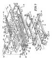
- FIG. 3is an exploded perspective view of portions of the hospital bed of FIG. 1 illustrating a base frame, a weigh frame, an intermediate frame, a retracting frame, an articulating deck, a first set of sensors for detecting the weight of a patient on the deck, and a second set of sensors located on the articulating deck for detecting the position of the patient on the deck;
- FIG. 4is a partial sectional view illustrating a load cell configured to connect the weigh frame to the base frame
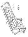
- FIG. 5is a perspective view of a head end siderail which includes a control panel for operating the patient position detection apparatus of the present invention
- FIG. 6is an enlarged view of the control panel of FIG. 5 which is used to control the mode of operation of the patient position detection apparatus and the volume of the alarms generated by the detection apparatus;
- FIG. 7is a block diagram illustrating the control electronics of the patient position detection apparatus
- FIG. 8is a top plan view of the articulating deck of the bed with the second set of sensors mounted on the deck;
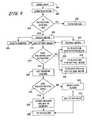
- FIGS. 9 and 10are flow charts illustrating a main loop of steps performed by the controller for monitoring inputs from the control panel and the first and second sets of sensors to control operation of the patient position detection apparatus in a position mode, an exiting mode, and an out-of-bed mode;
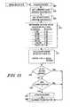
- FIG. 11is a flow chart illustrating steps performed by the controller in the position mode
- FIG. 12is a flow chart illustrating steps performed by the controller in the exiting mode
- FIG. 13is a flow chart illustrating steps performed by the controller in the out-of-bed mode
- FIG. 14is a perspective view of a first electrical connector alignment apparatus configured to be coupled to the footboard of the bed;
- FIG. 15is a perspective view of a second electrical connector alignment apparatus configured to be coupled to the retracting frame of the bed.
- FIG. 1illustrates a hospital bed 10 of the present invention.
- the bed 10includes a base frame 12 having a plurality of casters 14 and brake/steer control pedals 16 mounted adjacent each of the casters 14 . Details of the operation of the brake/steer control mechanism are disclosed in co-pending U.S. patent application Ser. No. 09/263,039, entitled CASTER AND BRAKING SYSTEM), now U.S. Pat. No. 6,321,878, filed Mar. 5, 1999, which is hereby incorporated by reference.
- the bed 10includes a weigh frame 18 coupled to the base frame 12 , an intermediate frame 19 coupled to the weigh frame 18 , a retracting frame 20 coupled to the intermediate frame 19 , and an articulating deck 22 coupled to the intermediate frame 19 and the retracting frame 20 .
- Brackets 21 on opposite sides of frame 20are configured to be coupled between the head section 106 and the thigh section 110 of deck 22 with suitable fasteners (not shown).
- the bed 10includes a headboard 24 mounted adjacent a head end 26 of the bed 10 and a footboard 28 mounted to the frame 20 adjacent a foot end 30 of bed 10 .
- Bed 10further includes a pair of head end siderails 32 and a pair of foot end siderails 34 mounted to the articulating deck 22 on opposite sides of the bed 10 . Further details of head end siderail 32 are illustrated in FIG. 5 .
- Siderails 32 and 34are coupled to the articulating deck 22 in a conventional manner using a connector mechanism 35 best shown in FIG. 5 .
- the siderails 32 and 34are movable from a lowered position shown in FIG. 1 to an elevated position (not shown) located above a top surface 36 of mattress 38 .
- Mattress 38is located on articulating deck 22 for supporting a patient thereon.
- the footboard 28includes a plurality of buttons, knobs, switches or other controls 40 for controlling various functions of the bed 10 .
- Controls 40are located on a top inclined panel 42 and a bottom inclined panel 44 on the footboard 28 .
- a cover 46is pivotably coupled to the footboard 28 by a pivot connection 48 so that the cover can be pivoted downwardly to conceal at least the controls 40 located on the top inclined panel 42 .
- One of the controls on the footboard 28is illustratively a lockout button 61 for entertainment functions which are controlled by patient input control panels on the bed 10 .
- a caregivercan press button 61 to lock out entertainment functions on the bed 10 .
- An indicator lightis provided adjacent the entertainment lockout control 61 to provide an indication when the entertainment lockout 61 is activated.
- the entertainment lockout control 61is illustratively located below the cover 46 on the footboard 28 . It is understood, however, that the entertainment lockout may be located at other positions on the bed.
- the bed 10also includes a plurality of lockout switches 63 which are illustratively located on the footboard 28 . It is understood that the lockout switches 63 may be located at any other position on the bed 10 .
- the lockout switches 63are coupled to the controller 50 to permit a caregiver to lock out selected functions which are normally controlled by the patient. Using patient controls that are typically located on the head end siderails 32 .
- lockout switches 63may deactivate controls for a night light, a back light, head or knee articulation, a hi/lo mechanism, or the entertainment devices discussed above.
- a master lockout switchis provided to lock out the head and knee articulation and the hi/lo control mechanism controls.
- Panel 42illustratively includes an indicator light (not shown) adjacent each of the lockout switches 63 to provide an indication when a particular lockout switch 63 is pressed.
- the bed 10includes a separate lockout indicator light 65 located at a location on the bed 10 spaced apart from the lockout switches 63 .
- the separate lockout indicator light 65is located on the head end siderail 32 as shown in FIG. 5 .
- Indicator light 65provides the nurse with a visual indication that one of the lockout switches 63 has been pressed.
- Footboard 28also includes side bumpers 66 and apertures 68 .
- Apertures 68provide handles to facilitate movement of the bed 10 .
- headboard 24 and footboard 28are made from a plastic material using a blow molding process. It is understood, however, that the headboard 24 and footboard 28 may be made from other materials and from other processes, if desired.
- the controls 40 on the footboard 28are electrically coupled to a controller 50 shown in FIG. 3 .
- the controller 50 and other bed electronicsare illustratively mounted on frame 20 .
- a first connector alignment apparatus 52is coupled to the footboard 28 and a second connector alignment apparatus 54 is coupled to the frame 20 .
- footboard 28is formed to include apertures 56 which slide over posts 58 on the frame 20 during installation of the footboard 28 onto the frame 20 in the direction of arrow 60 in FIG. 3 .
- Posts 58 and apertures 56therefore provide initial alignment between the footboard 28 and the frame 20 .
- First and second connector alignment apparatuses 52 and 54provide further alignment for male and female electrical connectors 62 and 64 , respectively, as discussed in detail below with reference to FIGS. 14-16 .
- the patient position detection apparatus of the present inventionuses two different types of sensors 70 , 104 .
- a first set of sensors 70is used to detect when a patient exits the bed 10 .
- a second set of sensors 104is used to determine a position of the patient on the deck 22 of the bed 10 .
- the first type of sensorsinclude load cells 70 which are mounted at the four corners of the weigh frame 18 . Details of the mounting of the load cells 70 between the base frame 12 and the weigh frame 18 are illustrated in FIGS. 3 and 4 .
- Base frame 12includes side frame members 72 and transverse frame members 74 extending between the side frame members 72 .
- Weigh frame 18includes a pair of hollow side frame members 76 .
- Load cells 70are well known. Load cells 70 typically include a plurality of strain gauges located within a metal block.
- a mounting ball 78is coupled to the load cell 70 .
- mounting ball 78includes a threaded stem which is screwed into threads in the load cell 70 .
- Mounting ball 78is located within an aperture 80 formed in a mounting block 82 .
- Mounting blocks 82are secured to the transverse frame members 74 by suitable fasteners 84 at the four corners of the base frame 12 .
- a mounting bar 86is coupled to an arm 88 of load cell 70 by fasteners 90 .
- Mounting bar 86is then secured to a top surface 92 of side frame member 76 of weigh frame 18 by suitable fasteners 94 and washers 96 .
- Mounting bar 86is not coupled to arm 98 of load cell 70 .
- load cell 70may be deflected downwardly in the direction of arrow 100 when weight is applied to the weigh frame 18 . Such deflection in the direction of arrow 100 changes an output voltage which provides an indication of weight change on the weigh frame.
- Load cells 70are coupled to a signal conditioner 53 by wires 102 .
- the signal conditioner 53is then coupled to the controller 50 on the bed 10 by wires 102 .
- the bed 10will typically include several controllers which control different functions on the bed. These controllers may be located at any location on the bed and are not limited to the location illustrated in FIG. 3 .
- the controllers 10typically are microprocessor based controllers. Output signals from various devices may need to be conditioned prior to being coupled to the controller. For instance, analog signals may need to be converted to digital signals for processing by the microprocessor of the controller. Therefore, the word controller is used broadly to include any type of control circuitry necessary to process the output signals and produce the desired control outputs or signals.
- a second set of sensors 104is illustrated in FIGS. 3 and 8 .
- Articulating deck 22includes a head deck section 106 , a seat deck section 108 , a thigh deck section 110 , and a leg deck section 112 .
- the second set of sensors 104includes a head section sensor 104 coupled to head deck section 106 by fasteners 116 .
- Sensor 114is elongated and extends along a longitudinal axis 118 of the deck 22 .
- Seat sensor 120is coupled to seat deck section 108 by fasteners 116 .
- Sensor 120extends in a direction transverse to the longitudinal axis 118 .
- Thigh sensors 122 and 124are coupled to thigh deck section 110 by fasteners 116 .
- the locations of sensors 114 , 120 , 122 , 124are further illustrated in FIG. 8 .
- sensors 114 , 120 , 122 , and 124are resistive pressure sensors available from Interlink Electronics.
- the resistive pressure sensorsare formed in strips which can be cut to any desired length.
- the sensor stripsare illustratively adhered to a stiffener and then sealed within a protective outer sleeve or cover made from a wipable material.
- Fasteners 116are illustratively rivets which secure the sensors 114 , 120 , 122 , and 124 in position on the deck 22 as best shown in FIG. 8 .
- Sensors 114 , 120 , 122 , and 124are coupled to the controller 50 on the bed 10 by wires 126 .
- the controller 50determines the position of the patient on the deck 22 . In particular, the controller 50 determines when the patient moves away from a central portion of the bed and too close to the side edges 23 or 25 on the deck 22 . Controller 50 then provides an indication that the patient is at risk of exiting the bed.
- the patient position detection apparatus of the present inventionis capable of operating in several different modes to assist the caregiver with tracking the patient position on the bed 10 .
- an out-of-bed modeonly sensors 70 are used to activate an alarm when a patient completely exits the bed.
- both sets of sensors 70 , 104are used.
- An alarmis activated when a patient is located at a position near the sides 23 , 25 of deck 22 or on the deck 22 near the head end 26 or foot end 30 .
- a pre-exit alarmis sounded when the patient moves outside a central portion of the deck 22 on the bed 10 .
- both sets of sensors 70 , 104are also used. An alarm is activated when a patient moves away from the head sensor 114 on the deck 22 as discussed below.
- FIG. 7is a block diagram illustrating the electronic control components of the patient position detection apparatus.
- the first and second sensors 70 and 104are each coupled to the controller 50 .
- the controller 50processes signals from the first and second sensors 70 , 104 as discussed in detail below to provide various control functions.
- a caregiver control panel 130is mounted on the bed 10 to control operation of the patient position detection apparatus.
- the caregiver control panel 130is mounted on the head end siderail 52 as best shown in FIG. 5 .
- the control panel 130may also be on a pendant or on a remote control device electrically coupled to the controller 50 .
- the caregiver control panel 130includes control buttons, switches, knobs, etc.
- the caregiver control panel 130includes control buttons, switches, knobs, etc. to set the particular type of detection mode for the apparatus as discussed below. Inputs from the caregiver control panel 130 are transmitted to the controller 50 . Controller 50 also transmits signals to the caregiver control panel 130 to control indicator lights 136 on the caregiver control panel 130 .
- controller 50controls either audible or visual local alarms 138 within the room or on the bed 10 . Controller 50 may also be used to turn on the room lights 140 when an alarm condition is detected. Finally, the controller 50 activates a nurse call alarm 142 to send an indication of the alarm condition to a nurse station located at a remote location.
- the apparatus of the present inventionfurther includes a nurse call reset or clear button 144 located on the bed 10 .
- This clear button 144sends a signal to controller 50 to clear the nurse call 142 alarm once the nurse call 142 alarm has been activated at the remote nurse call station.
- Nurse call clear button 144permits the caregiver to clear or reset the remote patient alarm while at the bed 10 after responding to the alarm condition.
- caregiversmust cancel the nurse call bed exit alarm 142 by returning to the nurse call station or by deactivating the alarm somewhere else in the hospital, other than at the bed 10 .
- Button 144permits the caregiver to clear the nurse call bed exit alarm 142 after responding to the alarm condition at the bed 10 .
- Controller 50is also coupled to a communication network 55 so that the controller 50 can transmit output signals to a remote location.
- controller 50is programmed to deactivate the local alarm 138 if the patient returns to bed 10 or returns to a correct position on the bed 10 depending upon the mode selected. This feature may encourage the patient to return to the correct position on the bed 10 since the alarm will be deactivated when the patient returns to the correct position.
- the nurse call alarm 142typically remains activated so that the caregiver may still respond to the alarm, even if the local audible and visual room alarm 138 is deactivated.
- FIG. 6illustrates further details of the caregiver control panel 130 which is illustratively located on the head end siderail 132 .
- Control panel 130includes a key button 150 , a mode control button 152 , and a volume control button 154 .
- the caregiverIn order to adjust the detection mode or volume of the alarm, the caregiver must depress the key button 150 and hold it down while depressing the desired mode button 152 or volume button 154 . With the key button 150 held down, the caregiver can scroll through the modes of operation by pressing the mode button 152 .
- Separate indicator LEDsare provided to indicate which mode is selected. The Position Mode is indicated by LED 156 , the Exiting Mode is indicated by LED 158 , and the Out-of-Bed Mode is indicated by LED 160 . If none of the LEDs 156 , 158 , 160 is lit, the patient position detection apparatus is off.
- Position Modeall three LEDs 156 , 158 , and 160 are lit. If the Exiting Mode is selected, LEDs 158 and 160 are lit. If the Out-of-Bed Mode is selected, only LED 160 is lit. By providing a different number of indicator lights for each of the three modes, a caregiver can tell which mode is selected in the dark.
- the patientis deterred from changing modes or volumes.
- the caregivercan change the volume of the alarm between a high setting, a medium setting, and a low setting by pressing the key button 150 and simultaneously pressing the volume button 154 . Subsequent presses of the volume button 154 change the volume to different levels.
- Indicator LEDs 162 , 164 , and 166are provided for the high, medium, and low volumes, respectively. If the high volume level is selected, all three LEDs 162 , 164 , and 168 are lit.
- LEDs 164 and 168are lit. If the low volume level is selected, only LED 168 is lit. By providing a different number of indicator lights for each volume level, a caregiver can tell the volume level for the alarm in the dark. When the patient position detection apparatus is off, all the volume LEDs 162 , 164 , and 168 are off.
- Position ModeWhen a local alarm condition is detected by controller 50 as discussed below.
- An appropriate LED for Position Mode, Exiting Mode, and Out-of-Bed Modewill flash on the control panel 30 to indicate an alarm condition for that mode. More than one of the LEDs 156 , 158 , and 160 can flash. For instance, in Position Mode, the Position Mode LED 156 may begin to flash when an alarm condition is detected by the Position Mode. Since the Out-of-Bed Mode is also run in Position Mode, the Out-of-Bed LED 160 may also be flashing if the patient has exited the bed.
- Caregiver control panel 130also includes an indicator LED 170 to provide an indication that the bed 10 is not down. This indicator LED 170 is lit when the deck 22 is not in its lowest position relative to the floor.
- caregiver panel 130includes an indicator LED 172 which provides an indication when the brake on the casters 14 is not set. When positioned in a room, the bed 10 is typically set so that the deck 22 is in its lowest position and the brake is set. Therefore, indicator LEDs 170 and 172 provide the caregiver with an indication that these conditions are not met.
- FIG. 8shows the illustrative arrangement of the sensors 114 , 120 , 122 , and 124 on the articulating deck 22 . It is understood that other arrangements of the second set of sensors 104 may be used in accordance with the present invention. In addition, additional sensors may be provided such as a sensor 125 located on the leg deck section 112 . Although the second sensors 104 are illustratively resistive sensors, it is understood that other types of sensors may be used in accordance with the present invention. For example, capacitance sensors such as shown in U.S. Pat. No. 5,808,552 or in U.S. patent application Ser. No. 09/031,749, now U.S. Pat. No.
- the second sensorsmay be used as the second sensors.
- a piezoelectric sensorsuch as disclosed in U.S. application Ser. No. 09/263,038, entitled A MONITORING SYSTEM AND METHOD) filed Mar. 5, 1999, now U.S. Pat. No. 6,252,512, which is hereby incorporated by reference may also be used.
- the sensors 104are coupled to a stop or bottom surface of the mattress 38 or are located within an interior region of the mattress 38 .
- FIGS. 9-12are flow charts illustrating operation of the controller 50 of the present invention and each of the three patient position detection modes.
- the main software loop of the controller 50is illustrated in FIGS. 9 and 10 .
- the main loopbegins at block 200 of FIG. 9 .
- Controller 50first updates the status of the indicator lights 136 on control panel 130 or elsewhere as illustrated at block 202 .
- Controller 50determines whether the patient detection system is on at block 204 . If the detection system is not on, controller 50 advances to block 230 as illustrated at block 205 . If the patient detection system is on, controller 50 checks the mode of the detection system as illustrated at block 206 . Specifically, controller 50 determines whether the detection system is in position mode as illustrated at block 208 , exiting mode as illustrated at block 210 , or out-of-bed mode as illustrated at block 212 .
- the controller 50will run the control loops for these modes as discussed below. After running the positioning mode loop or the exiting mode loop, the controller 50 will also run the out-of-bed mode loop when the controller is set in position mode or exiting mode. In other words, if the detection system is on, the out-of-bed mode will always be checked.
- Controller 50determines whether the mode was just activated at block 214 . If the particular mode was not just activated, the controller 50 advances to block 246 of FIG. 11 if the system is in position mode as illustrated at block 216 . If the particular mode was not just activated, controller 50 advances to block 264 of FIG. 12 if the system is in exiting mode as illustrated at block 218 . If the particular mode was not just activated, controller 50 advances to block 278 of FIG. 13 if the system is in out-of-bed mode as illustrated at block 220 .
- controller 50checks all the load cells 70 and sensors 114 , 120 , 122 , and 124 . To be within specification for exiting mode, the weight range detected by load cells 70 must be within a predetermined range based on average human weights. Controller 50 also determines whether any of the sensors 114 , 120 , 122 , or 124 are not plugged in or are shorted. In the out-of-bed mode, controller 50 only looks at load cells 70 to make sure that at least a predetermined minimum weight reading is obtained in order to indicate that a patient is on the bed 10 .
- controller 50will send a local alarm as illustrated at block 226 so that the caregiver can investigate the problem as illustrated at block 226 . Controller 50 then turns the detection system off as illustrated at block 227 and advances to block 230 as illustrated at block 229 . If the retrieved sensor values are within the specifications at block 224 , controller 50 stores all the sensor values in memory 51 as illustrated at block 228 . Controller 50 then advances to block 230 as illustrated at block 229 .
- the key button 150 on control panel 130is a hardware switch. If the key button 50 is not pressed, the controller 50 does not receive the signal from the mode button 152 or the volume button 154 . Therefore, if the key button is not pressed as illustrated at block 232 , controller 50 returns to block 200 as illustrated at block 244 . If the key button 150 and the mode button 152 are pressed as illustrated at block 234 , the controller 50 will receive an input based on the mode button press. If the key button 150 and the volume button 154 are pressed as illustrated at block 236 , the controller 50 will receive an input signal from the volume button 154 press.
- controller 50will receive input signals from both the mode button press and the volume button press. If the key button and at least one other button are pressed at blocks 234 , 236 , and 238 , controller 50 will update the mode and volume settings in memory 51 as illustrated at block 240 . Controller 50 then returns to block 200 as illustrated at block 244 .
- Controller 50Operation of the controller 50 in position mode is illustrated beginning at block 246 of FIG. 11 .
- Controller 50first reads the current value of head sensor 114 as illustrated at block 248 .
- the current head sensor valueis abbreviated as CV.
- controller 50retrieves the stored value for head sensor 114 which was stored in memory 51 at block 228 as illustrated at block 250 .
- the stored sensor valueis abbreviated as SV.
- Controller 50determines a scaler value based upon the stored head sensor value.
- an 8 bit A/D converteris used to convert the output from the sensors 104 . Therefore, the value SV ranges from 1-256 in the illustrated embodiment. Smaller values of SV indicate larger weight on the sensors 104 .
- Controller 50sets the scaler value as illustrated in the table at block 252 .
- the scaler valueremains constant until the mode is reactivated.
- controller 50calculates the acceptable range for the current head sensor value (CV) as illustrated at block 254 .
- the acceptable rangeis:
- Controller 50determines whether the current head sensor value CV is within the acceptable range as illustrated at block 256 . If so, controller 50 determines that the patient is in the proper position on the deck and returns to block 230 as illustrated at block 262 . If the current head sensor value is not within the acceptable range at block 256 , controller 50 determines whether a timer has expired at block 258 . If not, controller 50 advances back to block 230 . If the timer has expired, controller 50 determines that the patient is out of position and activates the local alarms 138 as illustrated at block 260 . Controller 50 also activates a nurse call alarm 142 , and may turn on the room lights 140 at block 260 . Controller 50 then advances to block 278 and runs the out-of-bed mode check as illustrated at block 262 .
- Controller 50advances to block 264 from block 218 in FIG. 9 .
- controller 50first runs the positioning mode loop as illustrated at block 266 .
- the controller 50uses head sensor 114 to check the patient's position using the flow chart discussed above in reference to FIG. 11 .
- Controller 50determines whether the current head sensor value CV is within the acceptable range as illustrated at block 268 . If so, controller 50 determines that the patient is in the proper position and advances to block 278 to run the out-of-bed mode check as illustrated at block 276 in FIG. 12 .
- Controller 50determines whether two of the three remaining sensors 120 , 122 , and 124 are within acceptable ranges as illustrated at block 272 by comparing the current sensor values to ranges based on the corresponding stored sensory values. If so, controller 50 determines that the patient is in an acceptable position on the deck 22 and advances at block 230 as illustrated at block 276 . If two of the three sensors are not within the acceptable ranges at block 272 , controller 50 determines that the patient is out of position and updates the local alarms 238 , activates the nurse call alarm 142 , and may turn on the room lights 140 as illustrated at block 274 . Controller 50 then advances to block 230 as illustrated at block 276 . In exiting mode, the patient position detection apparatus of the present invention permits the patient to move around more on the deck 22 before an alarm is activated compared to the position mode. Therefore, position mode is the most sensitive setting for the patient position detection apparatus of the present invention.
- sensors 104may be provided for the locations of sensors 104 .
- a different number of sensors 104may be used.
- the sensors 104may be mounted at different locations on the deck 22 , on the mattress 38 , or elsewhere on the bed 10 .
- Controller 50advances to block 278 from block 220 in FIG. 9 .
- controller 50detects an average current weight of the patient as illustrated at block 280 .
- the controller 50can take four readings from each load cell 70 and divide by four to get an average current weight.
- controller 50retrieves the stored initial weight from memory 51 as illustrated at block 282 .
- Controller 50subtracts the stored weight from the current weight as illustrated at block 284 .
- controller 286determines whether the weight on the bed 10 detected at block 280 has increased or decreased by more than 30 lbs. compared to the initial stored weight retrieved at block 282 . If the weight has not changed by more than 30 lbs., controller returns to block 230 as illustrated at block 294 . If the weight has changed by more than 30 lbs. at block 286 , controller 50 determines whether a timer has expired at block 288 . If the timer has not expired, controller 250 advances to block 230 as illustrated at block 294 . If the timer has expired at block 288 , the controller 50 determines whether the difference calculated at block 284 is less than ⁇ 30 lbs. at block 290 .
- controller 50determines that the patient has exited the bed 10 and updates the local alarms 138 , the nurse call alarm 142 and may turn on the room lights 140 as illustrated at block 292 . Controller 50 then returns to block 230 as illustrated at block 294 .
- controller 50determines whether the difference calculated at block 284 is greater than 30 lbs. as illustrated at block 296 . If so, controller 50 determines that substantial additional weight has been added to the bed and updates local alarms 138 only as illustrated at block 298 . The nurse call alarm 142 may also be activated, if desired. Controller 50 then advances to block 230 as illustrated at block 294 . If the difference is not greater than 30 lbs. at block 296 , controller 50 clears the local alarm only at block 300 and then advances to block 230 as illustrated at block 294 .
- the 30 lbs. threshold value for the out-of-bed modemay be adjusted upwardly or downwardly depending upon the weight of the patient. In other words, if the patient is particularly heavy, the 30 lb. threshold may be increased, for example.
- the patient detection apparatus of the present inventionmay have more than three modes of operation if desired.
- the separate modesmay have different sensitivity levels.
- the out-of-bed mode of the present inventionmay be armed with the patient in the bed 10 .
- the patientIn some beds having scales, the patient must be removed in order to determine a tare weight of the bed prior to the patient getting into the bed in order to arm the bed exit detector.
- removing the patient from the bedis not required in order to arm the bed exit detection system.
- the patient position detection system of the present inventionmay be quickly switched from a normal bed exit system in which an alarm is generated only when a patient exits the bed to a predictive bed exit system in which an alarm is generated when a patient moves away from a center portion of the bed.
- the output signals from the first and second set of sensors 70 , 104are monitored and stored, either at the bed 10 , or at a remote location to record movements of the patient.
- the controller 50 or a controller at the remote locationmonitors the sensor output values to determine whether the patient is moving on the bed 10 .
- the controller 50 or controller at a remote locationgenerates a caregiver alert signal or alarm if the patient has not moved on the bed within a predetermined period of time.
- the caregivercan go to the bed 10 and rotate the patient in order to reduce the likelihood that the patient will get bed sores. For example, if the patient hasn't moved for a predetermined period of time, such as two hours, a signal is generated advising the caregiver to move the patient. If the sensors 70 , 104 and controller detect that the patient has moved within the predetermined period, then there is no need for the caregiver to go turn the patient. Therefore, no signal is generated. This feature saves caregiver time and reduces the likelihood of injuries due to unnecessary rotation of a patient who has been moving.
- the output signals from the four sensors 70 located at the corners of the base frame 12are used to provide an indication when one of the frames or the deck hits an obstruction when moving from the high position to a low position.
- the processor 50determines when an output signal from one of the sensors 70 at the corners generates a negative value or a greatly reduced weight reading within a short period of time. This rapid change in the output signal indicates that an obstruction has been hit. Therefore, controller 50 can provide an output signal to stop the hi/lo mechanism from lowering the frames and deck. An alarm signal is also provided, if desired.
- FIGS. 14-16further illustrate the connector alignment apparatus of the present invention.
- the first connector alignment apparatus 52is illustrated in FIG. 14
- the second connector alignment apparatus 54is illustrated in FIG. 15
- Connector alignment apparatus 52is configured to receive a first pair of electrical connectors 62 shown in FIG. 16 which include a housing 304 having a first pair of spaced-apart flanges 306 and a second pair of spaced-apart flanges 308 .
- Flanges 308are each formed to include an aperture 310 .
- Connectors 302include a plurality of electrical terminals 312 extending away from housing 304 . Alignment posts 313 extend from housing 304 of connector 62 further than terminals 312 .
- the terminals 312are electrically connected to conductors of a cable 314 .
- Cable 314 of connectors 62are connected to controls 40 .
- Connector alignment apparatus 54is configured to receive female electrical connectors 64 . Those numbers referenced by numbers on connectors 62 perform the same or similar function.
- Connectors 64include female socket contacts 318 configured to receive terminals 312 of connector 302 .
- cables extending from connectors 64are coupled to the controller 50 on bed 10 .
- connector alignment apparatus 52includes a base plate 320 having outwardly extending alignment posts 322 located at opposite ends. Posts 322 each include tapered head portions 324 . Alignment apparatus 52 includes a pair of connector receiving portions 326 . Connector receiving portions 326 each include a pair of center posts 328 . Each post 328 includes a pair of spring arms 330 . Each spring arm 330 has a head portion 332 including a ramp surface 334 and a bottom lip 336 . Each connector receiving portion 326 also includes a pair of posts 338 .
- Electrical connectors 62are installed into the connector receiving portions 326 by locating the apertures 310 on flanges 308 over the posts 338 and pushing the connector 62 toward base 320 .
- Flanges 306engage ramp surfaces 334 of heads 332 and cause the spring arms 330 to be deflected. Once the flanges 306 move past the heads 332 , heads 332 then move over flanges 306 to retain the connectors 302 within the connector alignment apparatus 52 as best shown in FIG. 16 .
- Second connector alignment apparatus 54is best illustrated in FIG. 15 .
- the alignment apparatusincludes a body portion 340 having a pair of downwardly extending alignment posts 342 .
- Body portion 340is formed to include apertures 344 at opposite ends.
- Apertures 344are configured to receive the posts 322 of first connector alignment apparatus 52 as discussed below.
- Lead-in ramp surfaces 346are formed around the apertures 344 .
- Body portion 340further includes a pair of connector receiving portions 348 which function the same as connector receiving portions 326 described above. Reference numbers the same as in FIG. 14 perform the same or similar function.
- Apertures 310 formed in flanges 308 of connectors 64are inserted over the posts 338 of the connector receiving portions 348 .
- the connectors 64are then pushed downwardly to deflect the heads 332 until the lips 336 move over flanges 306 to lock the connectors 64 within the housing 340 as discussed above.
- the first connector alignment apparatus 52 and the second connector alignment apparatus 54each may include a key shown diagrammatically at locations 349 and 351 , respectively. Certain beds have different features which are controlled by controller 50 and actuated by controls 40 on the footboard. Therefore, different footboards 28 may be required depending upon the particular type of bed 10 being used.
- the keys 349 and 351 on the first and second connector alignment apparatuses 52 and 54only permit connection between an appropriate type of footboard 28 for the particular bed 10 . Therefore, the keys 349 and 351 ensure that the right type of footboard 28 is attached to the bed 10 .
- First connector alignment apparatus 52is rigidly coupled within a recessed portion 350 formed in footboard 28 as best shown in FIG. 16 .
- the base 320is secured to the footboard 28 by a fastener 352 which extends through an aperture 354 formed in the base 320 .
- the second connector alignment apparatus 54is loosely connected to an end surface 356 of the frame 20 .
- a fastener 358is configured to extend through an oversized central opening 360 formed in housing 340 .
- Posts 342 at opposite ends of the housing 340are located within apertures 362 formed in the surface 356 of the frame 20 . Housing 340 is therefore not rigidly coupled to frame 20 and can float slightly due to the oversized apertures 362 and the oversized aperture 360 .
- initial alignmentis provided by posts 58 on frame 20 extending into the apertures 56 formed in the footboard 28 .
- the posts 322 on first connector alignment apparatus 52enter the apertures 344 in the second connector alignment apparatus 54 .
- Tapered surfaces 324 on posts 22 and tapered surfaces 346 of apertures 344facilitate insertion of the posts 322 into the apertures 344 . Since the housing 340 of second connector alignment apparatus 54 can float on the frame 20 , the housing 340 moves into proper alignment with the first connector alignment apparatus 52 as the footboard 28 is installed. This ensures proper alignment between connectors 62 and 64 .
- connectors 62 and 64include further alignment posts 313 and apertures 315 , respectively, which mate to make sure that each of the terminals 312 line up with the socket contacts 318 . Therefore, the connector alignment apparatus of the present invention includes a combination of posts 58 on the frame 20 which mate with aperture 56 on the footboard 28 , posts 322 on the first connector alignment apparatus 52 which mate with apertures 344 on the second connector alignment apparatus 54 , and posts 313 on connectors 62 which mate with apertures 315 on the connectors 64 to provide further alignment.
Landscapes
- Health & Medical Sciences (AREA)
- Life Sciences & Earth Sciences (AREA)
- General Health & Medical Sciences (AREA)
- Public Health (AREA)
- Animal Behavior & Ethology (AREA)
- Veterinary Medicine (AREA)
- Nursing (AREA)
- Engineering & Computer Science (AREA)
- Physics & Mathematics (AREA)
- Biomedical Technology (AREA)
- Medical Informatics (AREA)
- General Physics & Mathematics (AREA)
- Business, Economics & Management (AREA)
- Dentistry (AREA)
- Physiology (AREA)
- Oral & Maxillofacial Surgery (AREA)
- Biophysics (AREA)
- Pathology (AREA)
- Heart & Thoracic Surgery (AREA)
- Molecular Biology (AREA)
- Surgery (AREA)
- Emergency Management (AREA)
- Epidemiology (AREA)
- Primary Health Care (AREA)
- General Business, Economics & Management (AREA)
- Invalid Beds And Related Equipment (AREA)
Abstract
Description
Claims (25)
Priority Applications (6)
| Application Number | Priority Date | Filing Date | Title |
|---|---|---|---|
| US11/851,535US7834768B2 (en) | 1999-03-05 | 2007-09-07 | Obstruction detection apparatus for a bed |
| US12/912,330US7978084B2 (en) | 1999-03-05 | 2010-10-26 | Body position monitoring system |
| US13/154,553US8258963B2 (en) | 1999-03-05 | 2011-06-07 | Body position monitoring system |
| US13/327,999US8400311B2 (en) | 1999-03-05 | 2011-12-16 | Hospital bed having alert light |
| US13/563,873US8525682B2 (en) | 1999-03-05 | 2012-08-01 | Hospital bed having alert light |
| US14/012,114US8830070B2 (en) | 1999-03-05 | 2013-08-28 | Hospital bed having alert light |
Applications Claiming Priority (7)
| Application Number | Priority Date | Filing Date | Title |
|---|---|---|---|
| US09/264,174US6208250B1 (en) | 1999-03-05 | 1999-03-05 | Patient position detection apparatus for a bed |
| US09/737,111US6320510B2 (en) | 1999-03-05 | 2000-12-14 | Bed control apparatus |
| US10/038,986US6791460B2 (en) | 1999-03-05 | 2001-11-19 | Patient position detection apparatus for a bed |
| US10/940,480US20050035871A1 (en) | 1999-03-05 | 2004-09-14 | Patient position detection apparatus for a bed |
| US11/088,468US20050166324A1 (en) | 1999-03-05 | 2005-03-24 | Romovable footboard for a hospital bed |
| US11/774,744US7986242B2 (en) | 1999-03-05 | 2007-07-09 | Electrical connector assembly suitable for a bed footboard |
| US11/851,535US7834768B2 (en) | 1999-03-05 | 2007-09-07 | Obstruction detection apparatus for a bed |
Related Parent Applications (6)
| Application Number | Title | Priority Date | Filing Date |
|---|---|---|---|
| US09/264,174DivisionUS6208250B1 (en) | 1999-03-05 | 1999-03-05 | Patient position detection apparatus for a bed |
| US09/737,111ContinuationUS6320510B2 (en) | 1999-03-05 | 2000-12-14 | Bed control apparatus |
| US10/038,986ContinuationUS6791460B2 (en) | 1999-03-05 | 2001-11-19 | Patient position detection apparatus for a bed |
| US10/940,480ContinuationUS20050035871A1 (en) | 1999-03-05 | 2004-09-14 | Patient position detection apparatus for a bed |
| US11/088,468ContinuationUS20050166324A1 (en) | 1999-03-05 | 2005-03-24 | Romovable footboard for a hospital bed |
| US11/774,744ContinuationUS7986242B2 (en) | 1999-03-05 | 2007-07-09 | Electrical connector assembly suitable for a bed footboard |
Related Child Applications (1)
| Application Number | Title | Priority Date | Filing Date |
|---|---|---|---|
| US12/912,330ContinuationUS7978084B2 (en) | 1999-03-05 | 2010-10-26 | Body position monitoring system |
Publications (2)
| Publication Number | Publication Date |
|---|---|
| US20070296600A1 US20070296600A1 (en) | 2007-12-27 |
| US7834768B2true US7834768B2 (en) | 2010-11-16 |
Family
ID=38947754
Family Applications (6)
| Application Number | Title | Priority Date | Filing Date |
|---|---|---|---|
| US11/851,535Expired - Fee RelatedUS7834768B2 (en) | 1999-03-05 | 2007-09-07 | Obstruction detection apparatus for a bed |
| US12/912,330Expired - Fee RelatedUS7978084B2 (en) | 1999-03-05 | 2010-10-26 | Body position monitoring system |
| US13/154,553Expired - Fee RelatedUS8258963B2 (en) | 1999-03-05 | 2011-06-07 | Body position monitoring system |
| US13/327,999Expired - Fee RelatedUS8400311B2 (en) | 1999-03-05 | 2011-12-16 | Hospital bed having alert light |
| US13/563,873Expired - Fee RelatedUS8525682B2 (en) | 1999-03-05 | 2012-08-01 | Hospital bed having alert light |
| US14/012,114Expired - Fee RelatedUS8830070B2 (en) | 1999-03-05 | 2013-08-28 | Hospital bed having alert light |
Family Applications After (5)
| Application Number | Title | Priority Date | Filing Date |
|---|---|---|---|
| US12/912,330Expired - Fee RelatedUS7978084B2 (en) | 1999-03-05 | 2010-10-26 | Body position monitoring system |
| US13/154,553Expired - Fee RelatedUS8258963B2 (en) | 1999-03-05 | 2011-06-07 | Body position monitoring system |
| US13/327,999Expired - Fee RelatedUS8400311B2 (en) | 1999-03-05 | 2011-12-16 | Hospital bed having alert light |
| US13/563,873Expired - Fee RelatedUS8525682B2 (en) | 1999-03-05 | 2012-08-01 | Hospital bed having alert light |
| US14/012,114Expired - Fee RelatedUS8830070B2 (en) | 1999-03-05 | 2013-08-28 | Hospital bed having alert light |
Country Status (1)
| Country | Link |
|---|---|
| US (6) | US7834768B2 (en) |
Cited By (32)
| Publication number | Priority date | Publication date | Assignee | Title |
|---|---|---|---|---|
| US20070180616A1 (en)* | 2006-02-08 | 2007-08-09 | Hill-Rom Services, Inc. | User module for a patient support |
| US20080172789A1 (en)* | 2005-12-19 | 2008-07-24 | Stryker Corporation | Patient support with improved control |
| US20110066287A1 (en)* | 2009-09-15 | 2011-03-17 | Joseph Flanagan | Article with Force Sensitive Motion Control Capability |
| US20110309944A1 (en)* | 2010-06-22 | 2011-12-22 | Ramanan Lakshminarayanan | Patient table system for medical system for medical applications and associated medical imaging device |
| US20120174319A1 (en)* | 1999-12-29 | 2012-07-12 | Menkedick Douglas J | Hospital Bed |
| US8258963B2 (en) | 1999-03-05 | 2012-09-04 | Hill-Rom Services, Inc. | Body position monitoring system |
| US8344860B2 (en) | 2004-08-02 | 2013-01-01 | Hill-Rom Services, Inc. | Patient support apparatus alert system |
| US8464380B2 (en) | 2005-07-08 | 2013-06-18 | Hill-Rom Services, Inc. | Patient support apparatus having alert light |
| US20130219382A1 (en)* | 2012-02-21 | 2013-08-22 | Troy PARSONS | Auto leveling low profile patient support apparatus |
| US8537008B2 (en) | 2008-09-19 | 2013-09-17 | Hill-Rom Services, Inc. | Bed status indicators |
| US20130340165A1 (en)* | 2011-03-09 | 2013-12-26 | Koninklijke Philips N.V. | Imaging system subject support |
| US20140221764A1 (en)* | 2013-01-31 | 2014-08-07 | Hill-Rom Services, Inc. | Stat clock for patient support apparatus |
| US8921717B2 (en) | 2012-11-05 | 2014-12-30 | S R Instruments, Inc. | Weight magnitude and weight position indication systems and methods |
| US8959681B2 (en) | 2010-12-20 | 2015-02-24 | Hill-Rom Services, Inc. | Ground sensor control of foot section retraction |
| US9177465B2 (en) | 2012-12-28 | 2015-11-03 | Hill-Rom Services, Inc. | Bed status system for a patient support apparatus |
| US9539155B2 (en) | 2012-10-26 | 2017-01-10 | Hill-Rom Services, Inc. | Control system for patient support apparatus |
| US9655798B2 (en) | 2013-03-14 | 2017-05-23 | Hill-Rom Services, Inc. | Multi-alert lights for hospital bed |
| US9875633B2 (en) | 2014-09-11 | 2018-01-23 | Hill-Rom Sas | Patient support apparatus |
| US10045715B2 (en) | 2015-04-27 | 2018-08-14 | Hill-Rom Services, Inc. | Self-compensating bed scale system for removable components |
| US10054479B2 (en) | 2015-05-05 | 2018-08-21 | Hill-Rom Services, Inc. | Bed with automatic weight offset detection and modification |
| US10130536B2 (en) | 2013-09-06 | 2018-11-20 | Stryker Corporation | Patient support usable with bariatric patients |
| US10188569B2 (en) | 2013-09-06 | 2019-01-29 | Stryker Corporation | Patient support usable with bariatric patients |
| US10206836B2 (en) | 2011-11-11 | 2019-02-19 | Hill-Rom Services, Inc. | Bed exit alerts for person support apparatus |
| US20190350780A1 (en)* | 2018-05-21 | 2019-11-21 | Hill-Rom Services, Inc. | Patient support apparatus adaptable to multiple modes of transport |
| US10634549B2 (en) | 2016-02-11 | 2020-04-28 | Hill-Rom Services, Inc. | Hospital bed scale calibration methods and patient position monitoring methods |
| US10842701B2 (en) | 2016-10-14 | 2020-11-24 | Stryker Corporation | Patient support apparatus with stabilization |
| US10945902B2 (en) | 2017-11-13 | 2021-03-16 | Stryker Corporation | Techniques for controlling actuators of a patient support apparatus |
| US11020297B2 (en) | 2015-12-22 | 2021-06-01 | Stryker Corporation | Powered side rail for a patient support apparatus |
| US11090209B2 (en) | 2017-06-20 | 2021-08-17 | Stryker Corporation | Patient support apparatus with control system and method to avoid obstacles during reconfiguration |
| US11213443B2 (en) | 2017-12-29 | 2022-01-04 | Stryker Corporation | Indication system to identify open space beneath patient support apparatus |
| US12036161B2 (en) | 2019-08-16 | 2024-07-16 | Stryker Corporation | Patient support with deck width monitoring and control |
| US12324776B2 (en) | 2022-04-28 | 2025-06-10 | Stryker Corporation | Patient support apparatus for treating patients presenting behavioral health indicia |
Families Citing this family (93)
| Publication number | Priority date | Publication date | Assignee | Title |
|---|---|---|---|---|
| US6791460B2 (en)* | 1999-03-05 | 2004-09-14 | Hill-Rom Services, Inc. | Patient position detection apparatus for a bed |
| WO2003088885A1 (en) | 2002-04-19 | 2003-10-30 | Hill-Rom Services, Inc. | Hospital bed obstacle detection device and method |
| GB0506691D0 (en)* | 2005-04-01 | 2005-05-11 | Pegasus Ltd | Height-adjustable bed |
| WO2007056342A2 (en)* | 2005-11-07 | 2007-05-18 | Stryker Corporation | Patient handling device including local status indication, one-touch fowler angle adjustment, and power-on alarm configuration |
| US11246776B2 (en) | 2005-12-19 | 2022-02-15 | Stryker Corporation | Patient support with improved control |
| DE102009010379B4 (en)* | 2008-03-03 | 2013-04-18 | Dieter Martin | Method for monitoring a person lying in a bed |
| EP2346404A4 (en)* | 2008-10-24 | 2013-12-18 | Hill Rom Services Inc | Apparatuses for supporting and monitoring a person |
| JP5424676B2 (en)* | 2009-03-13 | 2014-02-26 | キヤノン株式会社 | Image processing device |
| US8752220B2 (en)* | 2009-07-10 | 2014-06-17 | Hill-Rom Services, Inc. | Systems for patient support, monitoring and treatment |
| US8525680B2 (en) | 2009-09-18 | 2013-09-03 | Hill-Rom Services, Inc. | Apparatuses for supporting and monitoring a condition of a person |
| JP2013522588A (en) | 2010-03-12 | 2013-06-13 | エンハンスド サーフェイス ダイナミクス,インコーポレイテッド | System and method for fast collection of data from pressure sensors in a pressure sensing system |
| US9073575B2 (en)* | 2010-05-12 | 2015-07-07 | GM Global Technology Operations LLC | Memory features for a manually adjustable apparatus |
| US8508372B2 (en)* | 2010-06-21 | 2013-08-13 | General Electric Company | Method and system for fall detection |
| US20130139318A1 (en)* | 2010-08-06 | 2013-06-06 | Ohad Paz | Bed with weight bearing control system |
| US9013313B2 (en)* | 2011-01-18 | 2015-04-21 | Alan Paine | Bed pre-exit patient monitor |
| CN103476378A (en)* | 2011-04-12 | 2013-12-25 | 利纳克有限公司 | Electric actuator system |
| DE102011103284A1 (en)* | 2011-05-26 | 2012-11-29 | Rwe Effizienz Gmbh | Liege device |
| US20130127620A1 (en) | 2011-06-20 | 2013-05-23 | Cerner Innovation, Inc. | Management of patient fall risk |
| DE102011078567B4 (en)* | 2011-07-04 | 2014-08-28 | Siemens Aktiengesellschaft | Patient storage device for a medical imaging device, and a medical imaging device with the patient support device |
| US9741227B1 (en) | 2011-07-12 | 2017-08-22 | Cerner Innovation, Inc. | Method and process for determining whether an individual suffers a fall requiring assistance |
| US10546481B2 (en) | 2011-07-12 | 2020-01-28 | Cerner Innovation, Inc. | Method for determining whether an individual leaves a prescribed virtual perimeter |
| WO2013008187A1 (en) | 2011-07-13 | 2013-01-17 | Enhanced Surface Dynamics, Inc. | Methods and systems for the manufacture and initiation of a pressure detection mat |
| EP2763642B1 (en)* | 2011-10-03 | 2016-11-16 | Huntleigh Technology Limited | Multi-layered support system with electrically conductive spacer material |
| EP2766659B1 (en) | 2011-10-09 | 2017-05-17 | Stryker Corporation | Illuminable indicator for a bed |
| US8959082B2 (en) | 2011-10-31 | 2015-02-17 | Elwha Llc | Context-sensitive query enrichment |
| CN103945812B (en) | 2011-11-22 | 2017-06-30 | 八乐梦床业有限公司 | bed device |
| US20140310876A1 (en)* | 2011-12-16 | 2014-10-23 | Chg Hospital Beds Inc. | Patient support overload or obstruction detection |
| JP5946403B2 (en)* | 2011-12-24 | 2016-07-06 | 飯田 一喜 | Nursing bed |
| EP2803057A4 (en)* | 2012-01-13 | 2015-07-08 | Enhanced Surface Dynamics Inc | System and methods for risk management analysis of a pressure sensing system |
| US8978181B2 (en) | 2012-03-21 | 2015-03-17 | Midmark Corporation | Medical examination table with integrated scale |
| TW201340936A (en)* | 2012-04-11 | 2013-10-16 | Metal Ind Res & Dev Ct | Intelligent weight monitoring system and method thereof |
| EP2666406A3 (en)* | 2012-05-22 | 2013-12-04 | Hill-Rom Services, Inc. | Occupant egress prediction systems, methods and devices |
| US9228885B2 (en)* | 2012-06-21 | 2016-01-05 | Hill-Rom Services, Inc. | Patient support systems and methods of use |
| US20140025233A1 (en) | 2012-07-17 | 2014-01-23 | Elwha Llc | Unmanned device utilization methods and systems |
| US9798325B2 (en) | 2012-07-17 | 2017-10-24 | Elwha Llc | Unmanned device interaction methods and systems |
| US9306322B2 (en)* | 2012-08-23 | 2016-04-05 | Stryker Corporation | Patient support apparatus connectors |
| KR20140062891A (en)* | 2012-11-15 | 2014-05-26 | 삼성전자주식회사 | Cradle apparatus and control method thereof |
| US9173796B2 (en)* | 2013-02-05 | 2015-11-03 | Hill-Rom Services, Inc. | Bed with a powered width expansion wing with manual release |
| WO2015015288A1 (en)* | 2013-08-01 | 2015-02-05 | Rondish Co. Ltd. | Multifunction interface for patient monitoring |
| US9358169B2 (en)* | 2013-10-04 | 2016-06-07 | Gendron, Inc. | Drive system for bed |
| US10098797B2 (en)* | 2013-11-05 | 2018-10-16 | Hill-Rom Services, Inc. | Endboard for a person support apparatus |
| US10875482B2 (en)* | 2013-12-10 | 2020-12-29 | Maxon Industries, Inc. | Mounting system for vehicle underride |
| US10096223B1 (en) | 2013-12-18 | 2018-10-09 | Cerner Innovication, Inc. | Method and process for determining whether an individual suffers a fall requiring assistance |
| US10225522B1 (en) | 2014-01-17 | 2019-03-05 | Cerner Innovation, Inc. | Method and system for determining whether an individual takes appropriate measures to prevent the spread of healthcare-associated infections |
| US9729833B1 (en) | 2014-01-17 | 2017-08-08 | Cerner Innovation, Inc. | Method and system for determining whether an individual takes appropriate measures to prevent the spread of healthcare-associated infections along with centralized monitoring |
| US10078956B1 (en) | 2014-01-17 | 2018-09-18 | Cerner Innovation, Inc. | Method and system for determining whether an individual takes appropriate measures to prevent the spread of healthcare-associated infections |
| WO2015138317A1 (en) | 2014-03-10 | 2015-09-17 | Stryker Corporation | Limb positioning system |
| CA2902102C (en) | 2014-08-27 | 2023-02-14 | Umano Medical Inc. | Systems for patient support surface orientation and displacement |
| US10058468B2 (en)* | 2014-08-28 | 2018-08-28 | Umano Medical Inc. | Siderail system for a bed |
| US10786408B2 (en) | 2014-10-17 | 2020-09-29 | Stryker Corporation | Person support apparatuses with exit detection systems |
| CA2960740A1 (en)* | 2014-10-17 | 2016-04-21 | Stryker Corporation | Person support apparatuses with motion monitoring |
| US9771003B2 (en)* | 2014-10-29 | 2017-09-26 | Ford Global Technologies, Llc | Apparatus for customizing a vehicle seat for an occupant |
| US9711029B2 (en) | 2014-10-31 | 2017-07-18 | Hill-Rom Services, Inc. | Equipment, dressing and garment wireless connectivity to a patient bed |
| US10206834B2 (en) | 2014-12-11 | 2019-02-19 | Stryker Corporation | Obstruction detection system and method |
| US10090068B2 (en) | 2014-12-23 | 2018-10-02 | Cerner Innovation, Inc. | Method and system for determining whether a monitored individual's hand(s) have entered a virtual safety zone |
| US10524722B2 (en) | 2014-12-26 | 2020-01-07 | Cerner Innovation, Inc. | Method and system for determining whether a caregiver takes appropriate measures to prevent patient bedsores |
| USD770828S1 (en)* | 2015-01-29 | 2016-11-08 | Hill-Rom Services, Inc. | Footboard for patient bed |
| USD770827S1 (en)* | 2015-01-29 | 2016-11-08 | Hill-Rom Services, Inc. | Headboard for patient bed |
| US10091463B1 (en) | 2015-02-16 | 2018-10-02 | Cerner Innovation, Inc. | Method for determining whether an individual enters a prescribed virtual zone using 3D blob detection |
| US9951904B2 (en) | 2015-03-24 | 2018-04-24 | Stryker Corporation | Rotatable seat clamps for rail clamp |
| US10342478B2 (en) | 2015-05-07 | 2019-07-09 | Cerner Innovation, Inc. | Method and system for determining whether a caretaker takes appropriate measures to prevent patient bedsores |
| US9892611B1 (en) | 2015-06-01 | 2018-02-13 | Cerner Innovation, Inc. | Method for determining whether an individual enters a prescribed virtual zone using skeletal tracking and 3D blob detection |
| WO2016197221A1 (en)* | 2015-06-10 | 2016-12-15 | Sander Norberto André | System for monitoring beds of patients potentially at risk of falls |
| US10695246B2 (en)* | 2015-07-28 | 2020-06-30 | Stryker Corporation | Person support apparatus barrier |
| US10905609B2 (en) | 2015-11-20 | 2021-02-02 | Stryker Corporation | Patient support systems and methods for assisting caregivers with patient care |
| BR112018011315B1 (en)* | 2015-12-04 | 2023-04-11 | Arjo IP Holding Aktiebolag | PATIENT HANDLING APPLIANCE, BED SYSTEM, AND HOIST SYSTEM |
| US10614288B2 (en) | 2015-12-31 | 2020-04-07 | Cerner Innovation, Inc. | Methods and systems for detecting stroke symptoms |
| CA2917234A1 (en)* | 2016-01-11 | 2017-07-11 | Mackenzie Atlantic Tool And Die/Machining Ltd. | Slouch correction device and method |
| US10492734B2 (en) | 2016-11-04 | 2019-12-03 | Wellsense, Inc. | Patient visualization system |
| US11083418B2 (en) | 2016-11-04 | 2021-08-10 | Wellsense, Inc. | Patient visualization system |
| US10147184B2 (en) | 2016-12-30 | 2018-12-04 | Cerner Innovation, Inc. | Seizure detection |
| US11172892B2 (en) | 2017-01-04 | 2021-11-16 | Hill-Rom Services, Inc. | Patient support apparatus having vital signs monitoring and alerting |
| US10235845B2 (en)* | 2017-04-05 | 2019-03-19 | Stryker Corporation | Patient support apparatuses with reconfigurable communication |
| US10811136B2 (en) | 2017-06-27 | 2020-10-20 | Stryker Corporation | Access systems for use with patient support apparatuses |
| US11484451B1 (en) | 2017-06-27 | 2022-11-01 | Stryker Corporation | Patient support apparatus user interfaces |
| US11304865B2 (en) | 2017-06-27 | 2022-04-19 | Stryker Corporation | Patient support apparatus with adaptive user interface |
| US11337872B2 (en) | 2017-06-27 | 2022-05-24 | Stryker Corporation | Patient support systems and methods for assisting caregivers with patient care |
| US11810667B2 (en) | 2017-06-27 | 2023-11-07 | Stryker Corporation | Patient support systems and methods for assisting caregivers with patient care |
| US11096850B2 (en) | 2017-06-27 | 2021-08-24 | Stryker Corporation | Patient support apparatus control systems |
| US11202729B2 (en) | 2017-06-27 | 2021-12-21 | Stryker Corporation | Patient support apparatus user interfaces |
| US11382812B2 (en) | 2017-06-27 | 2022-07-12 | Stryker Corporation | Patient support systems and methods for assisting caregivers with patient care |
| EP3664696B1 (en)* | 2017-08-10 | 2024-05-01 | Parasol Medical LLC | Patient movement and incontinence notification system |
| US10643446B2 (en) | 2017-12-28 | 2020-05-05 | Cerner Innovation, Inc. | Utilizing artificial intelligence to detect objects or patient safety events in a patient room |
| US10482321B2 (en) | 2017-12-29 | 2019-11-19 | Cerner Innovation, Inc. | Methods and systems for identifying the crossing of a virtual barrier |
| US11957633B2 (en)* | 2018-04-30 | 2024-04-16 | Stryker Corporation | Patient transport apparatus having powered drive system utilizing coordinated user input devices |
| US11406548B2 (en) | 2018-09-27 | 2022-08-09 | Hill-Rom Services, Inc. | Obstacle detection IR beam filter |
| US10922936B2 (en) | 2018-11-06 | 2021-02-16 | Cerner Innovation, Inc. | Methods and systems for detecting prohibited objects |
| CN109998821B (en)* | 2019-05-14 | 2021-02-05 | 温州市中心医院 | A kind of integrated multifunctional nursing bed for hematology department |
| CA3085085A1 (en) | 2019-08-20 | 2021-02-20 | Stryker Corporation | Person support apparatus with adjustable exit detection zones |
| US12148512B2 (en) | 2019-12-31 | 2024-11-19 | Cerner Innovation, Inc. | Patient safety using virtual observation |
| US11573138B2 (en)* | 2020-01-08 | 2023-02-07 | Zebra Technologies Corporation | Doubly interlaced sensor array and method to support low power counting and identification |
| EP4221587A4 (en)* | 2020-09-30 | 2024-10-30 | Stryker Corporation | EXIT DETECTION SYSTEM WITH OBSTRUCTION REACTION |
| WO2023108243A1 (en) | 2021-12-16 | 2023-06-22 | Sociedade Beneficente De Senhoras - Hospital Sírio-Libanês | Fall prevention equipment |
Citations (64)
| Publication number | Priority date | Publication date | Assignee | Title |
|---|---|---|---|---|
| US3325799A (en) | 1964-07-13 | 1967-06-13 | Edwia Greines Cohen | Mattress alarm |
| US3504540A (en) | 1968-12-06 | 1970-04-07 | Us Army | Foot pad force measurement instrument |
| US3760794A (en) | 1971-09-01 | 1973-09-25 | Electronic Monitors Inc | Respiration monitoring apparatus and method |
| US3826145A (en) | 1973-03-01 | 1974-07-30 | Farland K Mc | Electrical ataxiameter |
| US3836900A (en) | 1973-01-26 | 1974-09-17 | Fleet Electronics Ltd | Recording or alarm devices |
| US3890958A (en) | 1974-04-08 | 1975-06-24 | Moog Automotive Inc | Physiological diagnostic apparatus |
| US3898981A (en) | 1971-09-01 | 1975-08-12 | Electronic Monitors Inc | Respiration monitoring apparatus |
| US3926177A (en) | 1972-09-11 | 1975-12-16 | Cavitron Corp | Activity and respiration monitor |
| USRE28754E (en) | 1973-03-05 | 1976-03-30 | William Beaumont Hospital | Bed egress alarm circuit |
| US3961201A (en) | 1974-09-06 | 1976-06-01 | Rosenthal Morris H | Patient monitoring |
| US3991414A (en) | 1971-08-02 | 1976-11-09 | Moran Jack L | Health care signaling device |
| US3991746A (en) | 1975-03-31 | 1976-11-16 | Medical R & D, Limited | Patient monitoring system and method |
| US4020482A (en) | 1976-04-19 | 1977-04-26 | Feldl Erich J | Patient monitor |
| US4051522A (en) | 1975-05-05 | 1977-09-27 | Jonathan Systems | Patient monitoring system |
| US4172216A (en) | 1978-05-19 | 1979-10-23 | Sprague Electric Company | Pressure sensitive switch |
| US4175263A (en) | 1977-04-25 | 1979-11-20 | Triad & Associates, Inc. | Technique for monitoring whether an individual is moving from a particular area |
| US4179692A (en) | 1977-05-05 | 1979-12-18 | Vance Dwight A | Apparatus to indicate when a patient has evacuated a bed or demonstrates a restless condition |
| US4195287A (en) | 1977-11-28 | 1980-03-25 | Mathis James C | Fire and absence detection and alarm system for bed occupants |
| US4228426A (en) | 1978-09-29 | 1980-10-14 | Roberts William A | Hospital bed monitor |
| US4242672A (en) | 1977-11-09 | 1980-12-30 | Gault Robert L | Patient monitoring system and switch |
| US4245651A (en) | 1979-03-13 | 1981-01-20 | Frost James K | Detecting body movements |
| US4264904A (en) | 1977-11-28 | 1981-04-28 | Mccoy Roy G | Fire and absence detection and alarm system for bed occupants |
| US4275385A (en) | 1979-08-13 | 1981-06-23 | Bell Telephone Laboratories, Incorporated | Infrared personnel locator system |
| US4295133A (en) | 1977-05-05 | 1981-10-13 | Vance Dwight A | Apparatus to indicate when a patient has evacuated a bed or demonstrates a restless condition |
| US4320766A (en) | 1979-03-13 | 1982-03-23 | Instrumentarium Oy | Apparatus in medicine for the monitoring and or recording of the body movements of a person on a bed, for instance of a patient |
| US4426884A (en) | 1982-02-01 | 1984-01-24 | The Langer Biomechanics Group, Inc. | Flexible force sensor |
| US4484043A (en) | 1982-09-30 | 1984-11-20 | Bed-Check Corporation | Switch apparatus responsive to pressure or distortion |
| US4539560A (en) | 1982-12-10 | 1985-09-03 | Hill-Rom Company, Inc. | Bed departure detection system |
| US4565910A (en) | 1982-09-30 | 1986-01-21 | Bed-Check Corporation | Switch apparatus responsive to distortion |
| US4601356A (en) | 1985-02-01 | 1986-07-22 | Muccillo Jr Vincent J | Suspended platform scale structure |
| US4633237A (en) | 1984-07-11 | 1986-12-30 | Kenneth A. Tucknott | Patient bed alarm system |
| US4638307A (en) | 1985-10-15 | 1987-01-20 | Swartout Willson C | Patient position monitoring system |
| US4669136A (en) | 1985-04-02 | 1987-06-02 | Med-Con Of Georgia, Inc. | Combination hospital bed and surgical table |
| US4700180A (en) | 1983-05-04 | 1987-10-13 | Vance Dwight A | Apparatus to indicate when a patient has evacuated a bed |
| US4793428A (en) | 1988-02-29 | 1988-12-27 | Cobe Asdt, Inc. | Hospital bed with an integrated scale |
| US4926951A (en) | 1989-06-26 | 1990-05-22 | Ssi Medical Services, Inc. | Weigh bed |
| US4934468A (en) | 1987-12-28 | 1990-06-19 | Hill-Rom Company, Inc. | Hospital bed for weighing patients |
| US4953244A (en) | 1987-12-28 | 1990-09-04 | Hill-Rom Company, Inc. | Hospital bed for weighing patients |
| US4974692A (en) | 1989-06-26 | 1990-12-04 | Ssi Medical Services, Inc. | Weigh bed |
| US5010774A (en) | 1987-11-05 | 1991-04-30 | The Yokohama Rubber Co., Ltd. | Distribution type tactile sensor |
| US5023967A (en) | 1988-03-23 | 1991-06-18 | American Life Support Technology | Patient support system |
| US5060174A (en) | 1990-04-18 | 1991-10-22 | Biomechanics Corporation Of America | Method and apparatus for evaluating a load bearing surface such as a seat |
| US5115223A (en) | 1990-09-20 | 1992-05-19 | Moody Thomas O | Personnel location monitoring system and method |
| US5144284A (en) | 1991-05-22 | 1992-09-01 | Hammett Rawlings H | Patient-monitoring bed covering device |
| US5170364A (en) | 1990-12-06 | 1992-12-08 | Biomechanics Corporation Of America | Feedback system for load bearing surface |
| US5253656A (en) | 1991-05-23 | 1993-10-19 | Rincoe Richard G | Apparatus and method for monitoring contact pressure between body parts and contact surfaces |
| US5269388A (en) | 1991-11-12 | 1993-12-14 | Stress-Tek, Inc. | Weighing bed |
| US5276432A (en) | 1992-01-15 | 1994-01-04 | Stryker Corporation | Patient exit detection mechanism for hospital bed |
| US5317769A (en)* | 1992-11-10 | 1994-06-07 | Hill-Rom Company, Inc. | Hospital bed |
| US5353012A (en) | 1992-05-14 | 1994-10-04 | Bartronix, Inc. | Bed position and activity sensing apparatus |
| US5393935A (en) | 1993-07-09 | 1995-02-28 | Ch Administration, Inc. | Portable scale |
| US5410297A (en) | 1993-01-11 | 1995-04-25 | R. F. Technologies, Inc. | Capacitive patient presence monitor |
| US5633627A (en) | 1994-09-23 | 1997-05-27 | Bed-Check Corporation | Hard-wired monitoring system for hospital bed or short term care patients |
| US5640145A (en) | 1994-10-11 | 1997-06-17 | Bed-Check Corporation | Remote controlled system for monitoring the occupancy of an infant bearing device |
| US5654694A (en) | 1994-09-23 | 1997-08-05 | Bed-Check Corporation | Mobile battery powered patient bed and chair occupancy monitoring system |
| US5699038A (en) | 1993-07-12 | 1997-12-16 | Hill-Rom, Inc. | Bed status information system for hospital beds |
| US5771511A (en) | 1995-08-04 | 1998-06-30 | Hill-Rom, Inc. | Communication network for a hospital bed |
| EP0860803A2 (en) | 1997-02-25 | 1998-08-26 | Lunan Products Limited | Carer's monitoring system |
| US5808552A (en) | 1996-11-25 | 1998-09-15 | Hill-Rom, Inc. | Patient detection system for a patient-support device |
| US5906016A (en) | 1988-03-23 | 1999-05-25 | Hill-Rom | Patient care system |
| US6067019A (en) | 1996-11-25 | 2000-05-23 | Hill-Rom, Inc. | Bed exit detection apparatus |
| US6163903A (en)* | 1994-01-25 | 2000-12-26 | Hill-Rom Inc. | Chair bed |
| US20090313758A1 (en)* | 1999-12-29 | 2009-12-24 | Menkedick Douglas J | Hospital bed |
| US7676866B2 (en)* | 2005-04-01 | 2010-03-16 | Pegasus Limited | Height-adjustable bedframes |
Family Cites Families (92)
| Publication number | Priority date | Publication date | Assignee | Title |
|---|---|---|---|---|
| US1078077A (en) | 1913-06-23 | 1913-11-11 | Nat Spring Bed Company | Bed. |
| US2527111A (en)* | 1947-10-07 | 1950-10-24 | Walter Brumbach | Vertically adjustable bed construction |
| GB1224904A (en) | 1968-08-09 | 1971-03-10 | John Stewart Simpson Stewart | Improvements in and relating to electromedical apparatus |
| US3802417A (en) | 1968-12-21 | 1974-04-09 | V Lang | Device for combined monitoring and stimulation of respiration |
| US3697846A (en) | 1971-02-11 | 1972-10-10 | American Hospital Supply Corp | Control system for hospital bed |
| US4197854A (en) | 1974-07-19 | 1980-04-15 | Medicor Muvek | Process and apparatus for patient danger recognition and forecasting of a danger condition, especially in case of intensive medical care |
| US4038709A (en) | 1975-12-24 | 1977-08-02 | Kerwit Medical Products, Inc. | Dual hydraulic hospital bed |
| US4097939A (en)* | 1976-02-18 | 1978-07-04 | Hill-Rom Company, Inc. | Hospital bed |
| US4183015A (en) | 1978-06-26 | 1980-01-08 | Hill-Rom Company, Inc. | Side guard for bed including means for controlling remote electrical devices |
| US4196425A (en) | 1978-07-10 | 1980-04-01 | by said David S. Weekly said Clyde E. Williams | Patient activity monitoring system |
| US4435862A (en) | 1981-10-19 | 1984-03-13 | Simmons Universal Corporation | Control arrangement and method for an adjustable bed |
| JPS5886179A (en) | 1981-11-18 | 1983-05-23 | 松下電器産業株式会社 | Laser medical apparatus |
| DE3313843C2 (en) | 1983-04-16 | 1986-01-16 | Volkmar 5600 Wuppertal Hahn | Sickbed |
| US4592104A (en)* | 1983-12-06 | 1986-06-03 | Hill-Rom Company, Inc. | Hospital bed |
| US4680790A (en) | 1985-08-22 | 1987-07-14 | Joerns Healthcare, Inc. | Bedside control module for healthcare stations and the like |
| USRE38419E1 (en) | 1986-05-13 | 2004-02-10 | Ncr Corporation | Computer interface device |
| US4751754A (en) | 1987-04-02 | 1988-06-21 | Hill-Rom Company, Inc. | Dual hydraulic hospital bed with emergency bypass circuit |
| US4803744A (en)* | 1987-05-19 | 1989-02-14 | Hill-Rom Company, Inc. | Inflatable bed |
| DE3716917C2 (en) | 1987-05-20 | 1996-07-18 | Franke Gmbh & Co Kg | Installation fitting for a bed frame |
| DE3734902C1 (en)* | 1987-10-15 | 1989-04-13 | Stollenwerk Fabrik Fuer Sanita | Carriage for a stretcher |
| US4907845A (en) | 1988-09-16 | 1990-03-13 | Salomon Sa | Bed patient monitoring system |
| US4998939A (en) | 1988-09-28 | 1991-03-12 | R & P Joint Venture | Hospital bed with guard rail actuated safety apparatus |
| JPH03502844A (en) | 1988-12-16 | 1991-06-27 | ベルゲル,ライマー | control device |
| US4953243A (en) | 1989-08-09 | 1990-09-04 | Amedco Health Care, Inc. | Electronic control with emergency CPR feature for adjustable bed |
| US5117521A (en)* | 1990-05-16 | 1992-06-02 | Hill-Rom Company, Inc. | Care cart and transport system |
| GB2252495B (en) | 1991-02-06 | 1994-12-14 | Nesbit Evans & Co Ltd | "Adjustable beds" |
| US5137033A (en) | 1991-07-15 | 1992-08-11 | Norton John L | Patient monitoring device |
| US5184112A (en) | 1991-09-11 | 1993-02-02 | Gaymar Industries, Inc. | Bed patient position monitor |
| US5195198A (en) | 1992-01-15 | 1993-03-23 | Stryker Corporation | Fail-safe bed motion control circuit having a microprocessor |
| US6131868A (en) | 1992-11-30 | 2000-10-17 | Hill-Rom, Inc. | Hospital bed communication and control device |
| US5377372A (en)* | 1993-03-31 | 1995-01-03 | Hill-Rom Company, Inc. | Hospital bed castor control mechanism |
| US5838223A (en) | 1993-07-12 | 1998-11-17 | Hill-Rom, Inc. | Patient/nurse call system |
| US5561412A (en) | 1993-07-12 | 1996-10-01 | Hill-Rom, Inc. | Patient/nurse call system |
| US6897780B2 (en)* | 1993-07-12 | 2005-05-24 | Hill-Rom Services, Inc. | Bed status information system for hospital beds |
| US5444880A (en) | 1993-11-03 | 1995-08-29 | Hill-Rom Company, Inc. | Bed with emergency head release and automatic knee down |
| US5450639A (en) | 1993-12-21 | 1995-09-19 | Hill-Rom Company, Inc. | Electrically activated visual indicator for visually indicating the mode of a hospital bed castor |
| US5502853A (en) | 1994-02-14 | 1996-04-02 | Sequin Hospital Bed Corp. | Bed frame with independently oscillating cradle |
| US5611096A (en) | 1994-05-09 | 1997-03-18 | Kinetic Concepts, Inc. | Positional feedback system for medical mattress systems |
| US6892405B1 (en)* | 1994-05-09 | 2005-05-17 | Kci Licensing, Inc. | Therapeutic bed and related apparatus and methods |
| US5664270A (en) | 1994-07-19 | 1997-09-09 | Kinetic Concepts, Inc. | Patient interface system |
| US5542138A (en) | 1995-02-06 | 1996-08-06 | Williams; Terry N. | Bedside control unit for a hospital bed |
| US5713856A (en) | 1995-03-13 | 1998-02-03 | Alaris Medical Systems, Inc. | Modular patient care system |
| US5830149A (en) | 1995-03-27 | 1998-11-03 | Colin Corporation | Physical information monitor system having means for indicating amount of deviation of monitored information from normal information |
| US7017208B2 (en)* | 1995-08-04 | 2006-03-28 | Hill-Rom Services, Inc. | Hospital bed |
| US5815865A (en) | 1995-11-30 | 1998-10-06 | Sleep Options, Inc. | Mattress structure |
| US5774914A (en) | 1996-01-05 | 1998-07-07 | Stryker Corporation | Maternity bed |
| US5806111A (en)* | 1996-04-12 | 1998-09-15 | Hill-Rom, Inc. | Stretcher controls |
| CA2181021C (en) | 1996-07-11 | 2007-10-02 | Eric Laganiere | Split side guards |
| JP2975894B2 (en) | 1996-07-12 | 1999-11-10 | 難波プレス工業株式会社 | Multi-layer seat of different hardness with skin and method of manufacturing the same |
| US5859390A (en)* | 1996-10-23 | 1999-01-12 | Hill-Rom, Inc. | Hospital bed scale mounting apparatus |
| US6000076A (en) | 1996-10-23 | 1999-12-14 | Hill-Rom, Inc. | Procedural stretcher recline controls |
| US5878452A (en) | 1996-12-03 | 1999-03-09 | Hill-Rom, Inc. | Long term care bed controls |
| US6057689A (en) | 1997-08-04 | 2000-05-02 | Gynecare, Inc. | Apparatus and method for leak detection in a fluid-filled balloon useful to treat body tissue |
| US6021533A (en) | 1997-08-25 | 2000-02-08 | Hill-Rom, Inc. | Mattress apparatus having a siderail down sensor |
| US7010369B2 (en) | 1997-11-07 | 2006-03-07 | Hill-Rom Services, Inc. | Medical equipment controller |
| US6240579B1 (en) | 1998-01-07 | 2001-06-05 | Stryker Corporation | Unitary pedal control of brake and fifth wheel deployment via side and end articulation with additional unitary pedal control of height of patient support |
| US6014346A (en)* | 1998-02-12 | 2000-01-11 | Accucure, L.L.C. | Medical timer/monitor and method of monitoring patient status |
| US6008598A (en) | 1998-04-22 | 1999-12-28 | Patmark Company, Inc. | Hand-held controller for bed and mattress assembly |
| US6188407B1 (en) | 1998-03-04 | 2001-02-13 | Critikon Company, Llc | Reconfigurable user interface for modular patient monitor |
| US6486792B1 (en) | 1998-04-14 | 2002-11-26 | Hill-Rom Services, Inc. | Communication and bed function control apparatus |
| EP1082038A2 (en)* | 1998-05-29 | 2001-03-14 | Hill-Rom, Inc. | Bed frame |
| US6286166B1 (en)* | 1998-06-19 | 2001-09-11 | Hill-Rom Services, Inc. | Modular foam mattress |
| US6199508B1 (en)* | 1998-06-22 | 2001-03-13 | Theresa Miale | Animal lift and transport apparatus |
| US6166644A (en) | 1998-09-10 | 2000-12-26 | Senior Technologies, Inc. | Patient monitoring system |
| US6049281A (en)* | 1998-09-29 | 2000-04-11 | Osterweil; Josef | Method and apparatus for monitoring movements of an individual |
| US6014784A (en) | 1998-10-19 | 2000-01-18 | Taylor; Rex E. | Portable system for generating variable pressure point body support |
| US6721980B1 (en)* | 1998-10-28 | 2004-04-20 | Hill-Fom Services, Inc. | Force optimization surface apparatus and method |
| US6078261A (en)* | 1998-11-10 | 2000-06-20 | Alert Systems, Inc. | System for monitoring a bed patient |
| US6180893B1 (en)* | 1999-03-03 | 2001-01-30 | Peter Salgo | Patient weighing apparatus |
| US6791460B2 (en)* | 1999-03-05 | 2004-09-14 | Hill-Rom Services, Inc. | Patient position detection apparatus for a bed |
| US6252512B1 (en) | 1999-03-05 | 2001-06-26 | Hill-Rom, Inc. | Monitoring system and method |
| US7834768B2 (en) | 1999-03-05 | 2010-11-16 | Hill-Rom Services, Inc. | Obstruction detection apparatus for a bed |
| US6321878B1 (en) | 1999-03-05 | 2001-11-27 | Hill-Rom Services, Inc. | Caster and braking system |
| US6208250B1 (en)* | 1999-03-05 | 2001-03-27 | Hill-Rom, Inc. | Patient position detection apparatus for a bed |
| EP1290652A2 (en) | 2000-05-05 | 2003-03-12 | Hill-Rom Services, Inc. | Hospital monitoring and control system and method |
| US7629890B2 (en)* | 2003-12-04 | 2009-12-08 | Hoana Medical, Inc. | System and methods for intelligent medical vigilance with bed exit detection |
| US7656299B2 (en)* | 2007-01-17 | 2010-02-02 | Hoana Medical, Inc. | Bed exit and patient detection system |
| EP1374194A2 (en)* | 2001-03-30 | 2004-01-02 | Hill-Rom Services, Inc. | Hospital bed and network system |
| US7154397B2 (en)* | 2001-08-03 | 2006-12-26 | Hill Rom Services, Inc. | Patient point-of-care computer system |
| JP4712385B2 (en)* | 2002-09-06 | 2011-06-29 | ヒル−ロム サービシーズ,インコーポレイティド | Hospital bed |
| JP4460276B2 (en) | 2003-12-12 | 2010-05-12 | エア・ウォーター防災株式会社 | Medical gas monitoring system |
| US7557718B2 (en)* | 2004-04-30 | 2009-07-07 | Hill-Rom Services, Inc. | Lack of patient movement monitor and method |
| US7319386B2 (en)* | 2004-08-02 | 2008-01-15 | Hill-Rom Services, Inc. | Configurable system for alerting caregivers |
| US7253366B2 (en) | 2004-08-09 | 2007-08-07 | Hill-Rom Services, Inc. | Exit alarm for a hospital bed triggered by individual load cell weight readings exceeding a predetermined threshold |
| US7155317B1 (en) | 2004-08-20 | 2006-12-26 | Nhan Tran | Occupant Counter Control Switch for automatic turning on and off electrical appliances in a room |
| WO2007056342A2 (en)* | 2005-11-07 | 2007-05-18 | Stryker Corporation | Patient handling device including local status indication, one-touch fowler angle adjustment, and power-on alarm configuration |
| US7657956B2 (en)* | 2006-08-04 | 2010-02-09 | Hill-Rom Services, Inc. | Patient support |
| US7768949B2 (en)* | 2007-02-22 | 2010-08-03 | Rauland-Borg Corporation | Communications system and protocol for medical environment |
| US7868740B2 (en)* | 2007-08-29 | 2011-01-11 | Hill-Rom Services, Inc. | Association of support surfaces and beds |
| US7789187B2 (en)* | 2008-01-29 | 2010-09-07 | Hill-Rom Services, Inc. | Push handle with pivotable handle post |
| US8299721B2 (en) | 2008-06-10 | 2012-10-30 | Telsa Controls Corporation | Systems and methods for rules based, automated lighting control |
| JP7107195B2 (en) | 2018-12-04 | 2022-07-27 | 株式会社豊田自動織機 | Electrolyte and power storage device |
- 2007
- 2007-09-07USUS11/851,535patent/US7834768B2/ennot_activeExpired - Fee Related
- 2010
- 2010-10-26USUS12/912,330patent/US7978084B2/ennot_activeExpired - Fee Related
- 2011
- 2011-06-07USUS13/154,553patent/US8258963B2/ennot_activeExpired - Fee Related
- 2011-12-16USUS13/327,999patent/US8400311B2/ennot_activeExpired - Fee Related
- 2012
- 2012-08-01USUS13/563,873patent/US8525682B2/ennot_activeExpired - Fee Related
- 2013
- 2013-08-28USUS14/012,114patent/US8830070B2/ennot_activeExpired - Fee Related
Patent Citations (66)
| Publication number | Priority date | Publication date | Assignee | Title |
|---|---|---|---|---|
| US3325799A (en) | 1964-07-13 | 1967-06-13 | Edwia Greines Cohen | Mattress alarm |
| US3504540A (en) | 1968-12-06 | 1970-04-07 | Us Army | Foot pad force measurement instrument |
| US3991414A (en) | 1971-08-02 | 1976-11-09 | Moran Jack L | Health care signaling device |
| US3760794A (en) | 1971-09-01 | 1973-09-25 | Electronic Monitors Inc | Respiration monitoring apparatus and method |
| US3898981A (en) | 1971-09-01 | 1975-08-12 | Electronic Monitors Inc | Respiration monitoring apparatus |
| US3926177A (en) | 1972-09-11 | 1975-12-16 | Cavitron Corp | Activity and respiration monitor |
| US3836900A (en) | 1973-01-26 | 1974-09-17 | Fleet Electronics Ltd | Recording or alarm devices |
| US3826145A (en) | 1973-03-01 | 1974-07-30 | Farland K Mc | Electrical ataxiameter |
| USRE28754E (en) | 1973-03-05 | 1976-03-30 | William Beaumont Hospital | Bed egress alarm circuit |
| US3890958A (en) | 1974-04-08 | 1975-06-24 | Moog Automotive Inc | Physiological diagnostic apparatus |
| US3961201A (en) | 1974-09-06 | 1976-06-01 | Rosenthal Morris H | Patient monitoring |
| US3991746A (en) | 1975-03-31 | 1976-11-16 | Medical R & D, Limited | Patient monitoring system and method |
| US4051522A (en) | 1975-05-05 | 1977-09-27 | Jonathan Systems | Patient monitoring system |
| US4020482A (en) | 1976-04-19 | 1977-04-26 | Feldl Erich J | Patient monitor |
| US4175263A (en) | 1977-04-25 | 1979-11-20 | Triad & Associates, Inc. | Technique for monitoring whether an individual is moving from a particular area |
| US4179692A (en) | 1977-05-05 | 1979-12-18 | Vance Dwight A | Apparatus to indicate when a patient has evacuated a bed or demonstrates a restless condition |
| US4295133A (en) | 1977-05-05 | 1981-10-13 | Vance Dwight A | Apparatus to indicate when a patient has evacuated a bed or demonstrates a restless condition |
| US4242672A (en) | 1977-11-09 | 1980-12-30 | Gault Robert L | Patient monitoring system and switch |
| US4195287A (en) | 1977-11-28 | 1980-03-25 | Mathis James C | Fire and absence detection and alarm system for bed occupants |
| US4264904A (en) | 1977-11-28 | 1981-04-28 | Mccoy Roy G | Fire and absence detection and alarm system for bed occupants |
| US4172216A (en) | 1978-05-19 | 1979-10-23 | Sprague Electric Company | Pressure sensitive switch |
| US4228426A (en) | 1978-09-29 | 1980-10-14 | Roberts William A | Hospital bed monitor |
| US4320766A (en) | 1979-03-13 | 1982-03-23 | Instrumentarium Oy | Apparatus in medicine for the monitoring and or recording of the body movements of a person on a bed, for instance of a patient |
| US4245651A (en) | 1979-03-13 | 1981-01-20 | Frost James K | Detecting body movements |
| US4275385A (en) | 1979-08-13 | 1981-06-23 | Bell Telephone Laboratories, Incorporated | Infrared personnel locator system |
| US4426884A (en) | 1982-02-01 | 1984-01-24 | The Langer Biomechanics Group, Inc. | Flexible force sensor |
| US4484043A (en) | 1982-09-30 | 1984-11-20 | Bed-Check Corporation | Switch apparatus responsive to pressure or distortion |
| US4565910A (en) | 1982-09-30 | 1986-01-21 | Bed-Check Corporation | Switch apparatus responsive to distortion |
| US4539560A (en) | 1982-12-10 | 1985-09-03 | Hill-Rom Company, Inc. | Bed departure detection system |
| US4700180A (en) | 1983-05-04 | 1987-10-13 | Vance Dwight A | Apparatus to indicate when a patient has evacuated a bed |
| US4633237A (en) | 1984-07-11 | 1986-12-30 | Kenneth A. Tucknott | Patient bed alarm system |
| US4601356A (en) | 1985-02-01 | 1986-07-22 | Muccillo Jr Vincent J | Suspended platform scale structure |
| US4669136A (en) | 1985-04-02 | 1987-06-02 | Med-Con Of Georgia, Inc. | Combination hospital bed and surgical table |
| US4638307A (en) | 1985-10-15 | 1987-01-20 | Swartout Willson C | Patient position monitoring system |
| US5010774A (en) | 1987-11-05 | 1991-04-30 | The Yokohama Rubber Co., Ltd. | Distribution type tactile sensor |
| US4934468A (en) | 1987-12-28 | 1990-06-19 | Hill-Rom Company, Inc. | Hospital bed for weighing patients |
| US4953244A (en) | 1987-12-28 | 1990-09-04 | Hill-Rom Company, Inc. | Hospital bed for weighing patients |
| US4793428A (en) | 1988-02-29 | 1988-12-27 | Cobe Asdt, Inc. | Hospital bed with an integrated scale |
| US5279010A (en) | 1988-03-23 | 1994-01-18 | American Life Support Technology, Inc. | Patient care system |
| US5023967A (en) | 1988-03-23 | 1991-06-18 | American Life Support Technology | Patient support system |
| US5906016A (en) | 1988-03-23 | 1999-05-25 | Hill-Rom | Patient care system |
| US5138729A (en) | 1988-03-23 | 1992-08-18 | American Life Support Technology | Patient support system |
| US4926951A (en) | 1989-06-26 | 1990-05-22 | Ssi Medical Services, Inc. | Weigh bed |
| US4974692A (en) | 1989-06-26 | 1990-12-04 | Ssi Medical Services, Inc. | Weigh bed |
| US5060174A (en) | 1990-04-18 | 1991-10-22 | Biomechanics Corporation Of America | Method and apparatus for evaluating a load bearing surface such as a seat |
| US5115223A (en) | 1990-09-20 | 1992-05-19 | Moody Thomas O | Personnel location monitoring system and method |
| US5170364A (en) | 1990-12-06 | 1992-12-08 | Biomechanics Corporation Of America | Feedback system for load bearing surface |
| US5144284A (en) | 1991-05-22 | 1992-09-01 | Hammett Rawlings H | Patient-monitoring bed covering device |
| US5253656A (en) | 1991-05-23 | 1993-10-19 | Rincoe Richard G | Apparatus and method for monitoring contact pressure between body parts and contact surfaces |
| US5269388A (en) | 1991-11-12 | 1993-12-14 | Stress-Tek, Inc. | Weighing bed |
| US5276432A (en) | 1992-01-15 | 1994-01-04 | Stryker Corporation | Patient exit detection mechanism for hospital bed |
| US5353012A (en) | 1992-05-14 | 1994-10-04 | Bartronix, Inc. | Bed position and activity sensing apparatus |
| US5317769A (en)* | 1992-11-10 | 1994-06-07 | Hill-Rom Company, Inc. | Hospital bed |
| US5410297A (en) | 1993-01-11 | 1995-04-25 | R. F. Technologies, Inc. | Capacitive patient presence monitor |
| US5393935A (en) | 1993-07-09 | 1995-02-28 | Ch Administration, Inc. | Portable scale |
| US5699038A (en) | 1993-07-12 | 1997-12-16 | Hill-Rom, Inc. | Bed status information system for hospital beds |
| US6163903A (en)* | 1994-01-25 | 2000-12-26 | Hill-Rom Inc. | Chair bed |
| US5633627A (en) | 1994-09-23 | 1997-05-27 | Bed-Check Corporation | Hard-wired monitoring system for hospital bed or short term care patients |
| US5654694A (en) | 1994-09-23 | 1997-08-05 | Bed-Check Corporation | Mobile battery powered patient bed and chair occupancy monitoring system |
| US5640145A (en) | 1994-10-11 | 1997-06-17 | Bed-Check Corporation | Remote controlled system for monitoring the occupancy of an infant bearing device |
| US5771511A (en) | 1995-08-04 | 1998-06-30 | Hill-Rom, Inc. | Communication network for a hospital bed |
| US5808552A (en) | 1996-11-25 | 1998-09-15 | Hill-Rom, Inc. | Patient detection system for a patient-support device |
| US6067019A (en) | 1996-11-25 | 2000-05-23 | Hill-Rom, Inc. | Bed exit detection apparatus |
| EP0860803A2 (en) | 1997-02-25 | 1998-08-26 | Lunan Products Limited | Carer's monitoring system |
| US20090313758A1 (en)* | 1999-12-29 | 2009-12-24 | Menkedick Douglas J | Hospital bed |
| US7676866B2 (en)* | 2005-04-01 | 2010-03-16 | Pegasus Limited | Height-adjustable bedframes |
Non-Patent Citations (2)
| Title |
|---|
| Advance Series Bed Services Manual (man026re) "4.37 Head Screw Assembly Chapter 4: Removal, Replacement, and Adjustment Procedures",Sep. 1998, pp. 89-106. |
| Advance Series Bed Services Manual (man026re) "Head Drive Unit Assembly-P/N 43353, 6200401 and 6200402; Chapter 5: Parts List", Sep. 1998, pp. 150-160. |
Cited By (76)
| Publication number | Priority date | Publication date | Assignee | Title |
|---|---|---|---|---|
| US8830070B2 (en) | 1999-03-05 | 2014-09-09 | Hill-Rom Services, Inc. | Hospital bed having alert light |
| US8525682B2 (en) | 1999-03-05 | 2013-09-03 | Hill-Rom Services, Inc. | Hospital bed having alert light |
| US8258963B2 (en) | 1999-03-05 | 2012-09-04 | Hill-Rom Services, Inc. | Body position monitoring system |
| US8400311B2 (en) | 1999-03-05 | 2013-03-19 | Hill-Rom Services, Inc. | Hospital bed having alert light |
| US9009893B2 (en)* | 1999-12-29 | 2015-04-21 | Hill-Rom Services, Inc. | Hospital bed |
| US20120174319A1 (en)* | 1999-12-29 | 2012-07-12 | Menkedick Douglas J | Hospital Bed |
| US8344860B2 (en) | 2004-08-02 | 2013-01-01 | Hill-Rom Services, Inc. | Patient support apparatus alert system |
| US8464380B2 (en) | 2005-07-08 | 2013-06-18 | Hill-Rom Services, Inc. | Patient support apparatus having alert light |
| US10561550B2 (en) | 2005-07-08 | 2020-02-18 | Hill-Rom Services, Inc. | Patient support apparatus having alert light |
| US9220650B2 (en) | 2005-07-08 | 2015-12-29 | Hill-Rom Services, Inc. | Patient support apparatus having alert light |
| US8544126B2 (en) | 2005-12-19 | 2013-10-01 | Stryker Corporation | Patient support with improved control |
| US20110144548A1 (en)* | 2005-12-19 | 2011-06-16 | Stryker Corporation | Patient suport with improved control |
| US20080172789A1 (en)* | 2005-12-19 | 2008-07-24 | Stryker Corporation | Patient support with improved control |
| US9038217B2 (en)* | 2005-12-19 | 2015-05-26 | Stryker Corporation | Patient support with improved control |
| US9827157B2 (en) | 2006-02-08 | 2017-11-28 | Hill-Rom Services, Inc. | User module for a patient support |
| US20070180616A1 (en)* | 2006-02-08 | 2007-08-09 | Hill-Rom Services, Inc. | User module for a patient support |
| US11786428B2 (en) | 2006-02-08 | 2023-10-17 | Hill-Rom Services, Inc. | User module for a patient support apparatus |
| US11617698B2 (en) | 2006-02-08 | 2023-04-04 | Hill-Rom Services, Inc. | User module for a patient support apparatus |
| US10842695B2 (en) | 2006-02-08 | 2020-11-24 | Hill-Rom Services, Inc. | User module for a patient support apparatus |
| US11273088B2 (en) | 2006-02-08 | 2022-03-15 | Hill-Rom Services, Inc. | User module for a patient support apparatus |
| US8537008B2 (en) | 2008-09-19 | 2013-09-17 | Hill-Rom Services, Inc. | Bed status indicators |
| US8593284B2 (en) | 2008-09-19 | 2013-11-26 | Hill-Rom Services, Inc. | System and method for reporting status of a bed |
| US8847756B2 (en) | 2008-09-19 | 2014-09-30 | Hill-Rom Services, Inc. | Bed status indicators |
| US20110066287A1 (en)* | 2009-09-15 | 2011-03-17 | Joseph Flanagan | Article with Force Sensitive Motion Control Capability |
| US8039766B2 (en)* | 2009-09-15 | 2011-10-18 | Hill-Rom Services, Inc. | Obstruction detecting force sensing system wherein the threshold force value for detecting an obstruction is set according to the configuration of the bed |
| US8633827B2 (en)* | 2010-06-22 | 2014-01-21 | General Electric Company | Patient table system for medical system for medical applications and associated medical imaging device |
| US20110309944A1 (en)* | 2010-06-22 | 2011-12-22 | Ramanan Lakshminarayanan | Patient table system for medical system for medical applications and associated medical imaging device |
| US8959681B2 (en) | 2010-12-20 | 2015-02-24 | Hill-Rom Services, Inc. | Ground sensor control of foot section retraction |
| US20130340165A1 (en)* | 2011-03-09 | 2013-12-26 | Koninklijke Philips N.V. | Imaging system subject support |
| US10285655B2 (en)* | 2011-03-09 | 2019-05-14 | Koninklijke Philips N.V. | Imaging system subject support |
| US10206836B2 (en) | 2011-11-11 | 2019-02-19 | Hill-Rom Services, Inc. | Bed exit alerts for person support apparatus |
| US20190046377A1 (en)* | 2012-02-21 | 2019-02-14 | Sizewise Rentals, L.L.C. | Auto leveling low profile patient support apparatus |
| US20130219382A1 (en)* | 2012-02-21 | 2013-08-22 | Troy PARSONS | Auto leveling low profile patient support apparatus |
| US12150904B2 (en)* | 2012-02-21 | 2024-11-26 | Sizewise Rentals, L.L.C. | Auto leveling low profile patient support apparatus |
| US10123923B2 (en)* | 2012-02-21 | 2018-11-13 | Sizewise Rentals, L.L.C. | Auto leveling low profile patient support apparatus |
| US10512573B2 (en) | 2012-10-26 | 2019-12-24 | Hill-Rom Services, Inc. | Control system for patient support apparatus |
| US9539155B2 (en) | 2012-10-26 | 2017-01-10 | Hill-Rom Services, Inc. | Control system for patient support apparatus |
| US8921717B2 (en) | 2012-11-05 | 2014-12-30 | S R Instruments, Inc. | Weight magnitude and weight position indication systems and methods |
| US9489818B2 (en) | 2012-12-28 | 2016-11-08 | Hill-Rom Services, Inc. | Bed status system for a patient support apparatus |
| US9177465B2 (en) | 2012-12-28 | 2015-11-03 | Hill-Rom Services, Inc. | Bed status system for a patient support apparatus |
| US20140221764A1 (en)* | 2013-01-31 | 2014-08-07 | Hill-Rom Services, Inc. | Stat clock for patient support apparatus |
| US10709625B2 (en) | 2013-03-14 | 2020-07-14 | Hill-Rom Services, Inc. | Foot end alert display for hospital bed |
| US12186249B2 (en) | 2013-03-14 | 2025-01-07 | Hill-Rom Services, Inc. | Multi-alert lights for hospital bed |
| US11833090B2 (en) | 2013-03-14 | 2023-12-05 | Hill-Rom Services, Inc. | Multi-alert lights for hospital bed |
| US10512574B2 (en) | 2013-03-14 | 2019-12-24 | Hill-Rom Services, Inc. | Multi-alert lights for hospital bed |
| US10413465B2 (en) | 2013-03-14 | 2019-09-17 | Hill-Rom Services, Inc. | Multi-alert lights for hospital bed |
| US9655798B2 (en) | 2013-03-14 | 2017-05-23 | Hill-Rom Services, Inc. | Multi-alert lights for hospital bed |
| US10918546B2 (en) | 2013-03-14 | 2021-02-16 | Hill-Rom Services, Inc. | Multi-alert lights for hospital bed |
| US11464692B2 (en) | 2013-03-14 | 2022-10-11 | Hill-Rom Services, Inc. | Multi-alert lights for hospital bed |
| US10842694B2 (en) | 2013-09-06 | 2020-11-24 | Stryker Corporation | Patient support usable with bariatric patients |
| US11865056B2 (en) | 2013-09-06 | 2024-01-09 | Stryker Corporation | Patient support usable with bariatric patients |
| US10716722B2 (en) | 2013-09-06 | 2020-07-21 | Stryker Corporation | Patient support usable with bariatric patients |
| US10188569B2 (en) | 2013-09-06 | 2019-01-29 | Stryker Corporation | Patient support usable with bariatric patients |
| US10130536B2 (en) | 2013-09-06 | 2018-11-20 | Stryker Corporation | Patient support usable with bariatric patients |
| US11285061B2 (en) | 2013-09-06 | 2022-03-29 | Stryker Corporation | Patient support usable with bariatric patients |
| US11980580B2 (en) | 2013-09-06 | 2024-05-14 | Stryker Corporation | Patient support usable with bariatric patients |
| US11419776B2 (en) | 2013-09-06 | 2022-08-23 | Stryker Corporation | Patient support usable with bariatric patients |
| US10276021B2 (en) | 2014-09-11 | 2019-04-30 | Hill-Rom Sas | Patient support apparatus having articulated mattress support deck with load sensors |
| US9875633B2 (en) | 2014-09-11 | 2018-01-23 | Hill-Rom Sas | Patient support apparatus |
| US10660544B2 (en) | 2015-04-27 | 2020-05-26 | Hill-Rom Services, Inc. | Self-compensating bed scale system for removable components |
| US10045715B2 (en) | 2015-04-27 | 2018-08-14 | Hill-Rom Services, Inc. | Self-compensating bed scale system for removable components |
| US10054479B2 (en) | 2015-05-05 | 2018-08-21 | Hill-Rom Services, Inc. | Bed with automatic weight offset detection and modification |
| US11020297B2 (en) | 2015-12-22 | 2021-06-01 | Stryker Corporation | Powered side rail for a patient support apparatus |
| US11998499B2 (en) | 2015-12-22 | 2024-06-04 | Stryker Corporation | Powered side rail for a patient support apparatus |
| US10634549B2 (en) | 2016-02-11 | 2020-04-28 | Hill-Rom Services, Inc. | Hospital bed scale calibration methods and patient position monitoring methods |
| US10842701B2 (en) | 2016-10-14 | 2020-11-24 | Stryker Corporation | Patient support apparatus with stabilization |
| US11090209B2 (en) | 2017-06-20 | 2021-08-17 | Stryker Corporation | Patient support apparatus with control system and method to avoid obstacles during reconfiguration |
| US11806292B2 (en) | 2017-11-13 | 2023-11-07 | Stryker Corporation | Techniques for controlling actuators of a patient support apparatus |
| US11389353B2 (en) | 2017-11-13 | 2022-07-19 | Stryker Corporation | Techniques for controlling actuators of a patient support apparatus |
| US10945902B2 (en) | 2017-11-13 | 2021-03-16 | Stryker Corporation | Techniques for controlling actuators of a patient support apparatus |
| US11213443B2 (en) | 2017-12-29 | 2022-01-04 | Stryker Corporation | Indication system to identify open space beneath patient support apparatus |
| US11628102B2 (en)* | 2018-05-21 | 2023-04-18 | Hill-Rom Services, Inc. | Patient support apparatus adaptable to multiple modes of transport |
| US20190350780A1 (en)* | 2018-05-21 | 2019-11-21 | Hill-Rom Services, Inc. | Patient support apparatus adaptable to multiple modes of transport |
| US12336941B2 (en) | 2018-05-21 | 2025-06-24 | Hill-Rom Services, Inc. | Patient support apparatus having detachable barrier assembly |
| US12036161B2 (en) | 2019-08-16 | 2024-07-16 | Stryker Corporation | Patient support with deck width monitoring and control |
| US12324776B2 (en) | 2022-04-28 | 2025-06-10 | Stryker Corporation | Patient support apparatus for treating patients presenting behavioral health indicia |
Also Published As
| Publication number | Publication date |
|---|---|
| US20140000032A1 (en) | 2014-01-02 |
| US8525682B2 (en) | 2013-09-03 |
| US20110234408A1 (en) | 2011-09-29 |
| US8830070B2 (en) | 2014-09-09 |
| US20120086575A1 (en) | 2012-04-12 |
| US8258963B2 (en) | 2012-09-04 |
| US20110037597A1 (en) | 2011-02-17 |
| US7978084B2 (en) | 2011-07-12 |
| US20120291200A1 (en) | 2012-11-22 |
| US20070296600A1 (en) | 2007-12-27 |
| US8400311B2 (en) | 2013-03-19 |
Similar Documents
| Publication | Publication Date | Title |
|---|---|---|
| US7834768B2 (en) | Obstruction detection apparatus for a bed | |
| CA2362788C (en) | Patient position detection apparatus for a bed | |
| US6791460B2 (en) | Patient position detection apparatus for a bed | |
| EP1754462B1 (en) | Patient support with actuator control member | |
| US7533429B2 (en) | Lift system for hospital bed |
Legal Events
| Date | Code | Title | Description |
|---|---|---|---|
| STCF | Information on status: patent grant | Free format text:PATENTED CASE | |
| FPAY | Fee payment | Year of fee payment:4 | |
| AS | Assignment | Owner name:JPMORGAN CHASE BANK, N.A., AS COLLATERAL AGENT, ILLINOIS Free format text:SECURITY INTEREST;ASSIGNORS:ALLEN MEDICAL SYSTEMS, INC.;HILL-ROM SERVICES, INC.;ASPEN SURGICAL PRODUCTS, INC.;AND OTHERS;REEL/FRAME:036582/0123 Effective date:20150908 Owner name:JPMORGAN CHASE BANK, N.A., AS COLLATERAL AGENT, IL Free format text:SECURITY INTEREST;ASSIGNORS:ALLEN MEDICAL SYSTEMS, INC.;HILL-ROM SERVICES, INC.;ASPEN SURGICAL PRODUCTS, INC.;AND OTHERS;REEL/FRAME:036582/0123 Effective date:20150908 | |
| AS | Assignment | Owner name:JPMORGAN CHASE BANK, N.A., AS COLLATERAL AGENT, ILLINOIS Free format text:SECURITY AGREEMENT;ASSIGNORS:HILL-ROM SERVICES, INC.;ASPEN SURGICAL PRODUCTS, INC.;ALLEN MEDICAL SYSTEMS, INC.;AND OTHERS;REEL/FRAME:040145/0445 Effective date:20160921 Owner name:JPMORGAN CHASE BANK, N.A., AS COLLATERAL AGENT, IL Free format text:SECURITY AGREEMENT;ASSIGNORS:HILL-ROM SERVICES, INC.;ASPEN SURGICAL PRODUCTS, INC.;ALLEN MEDICAL SYSTEMS, INC.;AND OTHERS;REEL/FRAME:040145/0445 Effective date:20160921 | |
| MAFP | Maintenance fee payment | Free format text:PAYMENT OF MAINTENANCE FEE, 8TH YEAR, LARGE ENTITY (ORIGINAL EVENT CODE: M1552) Year of fee payment:8 | |
| AS | Assignment | Owner name:HILL-ROM SERVICES, INC., ILLINOIS Free format text:RELEASE BY SECURED PARTY;ASSIGNOR:JPMORGAN CHASE BANK, N.A.;REEL/FRAME:050254/0513 Effective date:20190830 Owner name:ANODYNE MEDICAL DEVICE, INC., FLORIDA Free format text:RELEASE BY SECURED PARTY;ASSIGNOR:JPMORGAN CHASE BANK, N.A.;REEL/FRAME:050254/0513 Effective date:20190830 Owner name:HILL-ROM, INC., ILLINOIS Free format text:RELEASE BY SECURED PARTY;ASSIGNOR:JPMORGAN CHASE BANK, N.A.;REEL/FRAME:050254/0513 Effective date:20190830 Owner name:MORTARA INSTRUMENT, INC., WISCONSIN Free format text:RELEASE BY SECURED PARTY;ASSIGNOR:JPMORGAN CHASE BANK, N.A.;REEL/FRAME:050254/0513 Effective date:20190830 Owner name:MORTARA INSTRUMENT SERVICES, INC., WISCONSIN Free format text:RELEASE BY SECURED PARTY;ASSIGNOR:JPMORGAN CHASE BANK, N.A.;REEL/FRAME:050254/0513 Effective date:20190830 Owner name:ALLEN MEDICAL SYSTEMS, INC., ILLINOIS Free format text:RELEASE BY SECURED PARTY;ASSIGNOR:JPMORGAN CHASE BANK, N.A.;REEL/FRAME:050254/0513 Effective date:20190830 Owner name:VOALTE, INC., FLORIDA Free format text:RELEASE BY SECURED PARTY;ASSIGNOR:JPMORGAN CHASE BANK, N.A.;REEL/FRAME:050254/0513 Effective date:20190830 Owner name:WELCH ALLYN, INC., NEW YORK Free format text:RELEASE BY SECURED PARTY;ASSIGNOR:JPMORGAN CHASE BANK, N.A.;REEL/FRAME:050254/0513 Effective date:20190830 Owner name:HILL-ROM COMPANY, INC., ILLINOIS Free format text:RELEASE BY SECURED PARTY;ASSIGNOR:JPMORGAN CHASE BANK, N.A.;REEL/FRAME:050254/0513 Effective date:20190830 | |
| AS | Assignment | Owner name:JPMORGAN CHASE BANK, N.A., ILLINOIS Free format text:SECURITY AGREEMENT;ASSIGNORS:HILL-ROM HOLDINGS, INC.;HILL-ROM, INC.;HILL-ROM SERVICES, INC.;AND OTHERS;REEL/FRAME:050260/0644 Effective date:20190830 | |
| AS | Assignment | Owner name:HILL-ROM HOLDINGS, INC., ILLINOIS Free format text:RELEASE OF SECURITY INTEREST AT REEL/FRAME 050260/0644;ASSIGNOR:JPMORGAN CHASE BANK, N.A.;REEL/FRAME:058517/0001 Effective date:20211213 Owner name:BARDY DIAGNOSTICS, INC., ILLINOIS Free format text:RELEASE OF SECURITY INTEREST AT REEL/FRAME 050260/0644;ASSIGNOR:JPMORGAN CHASE BANK, N.A.;REEL/FRAME:058517/0001 Effective date:20211213 Owner name:VOALTE, INC., FLORIDA Free format text:RELEASE OF SECURITY INTEREST AT REEL/FRAME 050260/0644;ASSIGNOR:JPMORGAN CHASE BANK, N.A.;REEL/FRAME:058517/0001 Effective date:20211213 Owner name:HILL-ROM, INC., ILLINOIS Free format text:RELEASE OF SECURITY INTEREST AT REEL/FRAME 050260/0644;ASSIGNOR:JPMORGAN CHASE BANK, N.A.;REEL/FRAME:058517/0001 Effective date:20211213 Owner name:WELCH ALLYN, INC., NEW YORK Free format text:RELEASE OF SECURITY INTEREST AT REEL/FRAME 050260/0644;ASSIGNOR:JPMORGAN CHASE BANK, N.A.;REEL/FRAME:058517/0001 Effective date:20211213 Owner name:ALLEN MEDICAL SYSTEMS, INC., ILLINOIS Free format text:RELEASE OF SECURITY INTEREST AT REEL/FRAME 050260/0644;ASSIGNOR:JPMORGAN CHASE BANK, N.A.;REEL/FRAME:058517/0001 Effective date:20211213 Owner name:HILL-ROM SERVICES, INC., ILLINOIS Free format text:RELEASE OF SECURITY INTEREST AT REEL/FRAME 050260/0644;ASSIGNOR:JPMORGAN CHASE BANK, N.A.;REEL/FRAME:058517/0001 Effective date:20211213 Owner name:BREATHE TECHNOLOGIES, INC., CALIFORNIA Free format text:RELEASE OF SECURITY INTEREST AT REEL/FRAME 050260/0644;ASSIGNOR:JPMORGAN CHASE BANK, N.A.;REEL/FRAME:058517/0001 Effective date:20211213 | |
| FEPP | Fee payment procedure | Free format text:MAINTENANCE FEE REMINDER MAILED (ORIGINAL EVENT CODE: REM.); ENTITY STATUS OF PATENT OWNER: LARGE ENTITY | |
| LAPS | Lapse for failure to pay maintenance fees | Free format text:PATENT EXPIRED FOR FAILURE TO PAY MAINTENANCE FEES (ORIGINAL EVENT CODE: EXP.); ENTITY STATUS OF PATENT OWNER: LARGE ENTITY | |
| STCH | Information on status: patent discontinuation | Free format text:PATENT EXPIRED DUE TO NONPAYMENT OF MAINTENANCE FEES UNDER 37 CFR 1.362 | |
| FP | Lapsed due to failure to pay maintenance fee | Effective date:20221116 |