US7834621B2 - Electromagnetic tracking employing scalar-magnetometer - Google Patents
Electromagnetic tracking employing scalar-magnetometerDownload PDFInfo
- Publication number
- US7834621B2 US7834621B2US11/860,649US86064907AUS7834621B2US 7834621 B2US7834621 B2US 7834621B2US 86064907 AUS86064907 AUS 86064907AUS 7834621 B2US7834621 B2US 7834621B2
- Authority
- US
- United States
- Prior art keywords
- magnetic field
- scalar
- magnetometer
- transmitter
- receiver
- Prior art date
- Legal status (The legal status is an assumption and is not a legal conclusion. Google has not performed a legal analysis and makes no representation as to the accuracy of the status listed.)
- Active, expires
Links
Images


Classifications
- G—PHYSICS
- G01—MEASURING; TESTING
- G01R—MEASURING ELECTRIC VARIABLES; MEASURING MAGNETIC VARIABLES
- G01R31/00—Arrangements for testing electric properties; Arrangements for locating electric faults; Arrangements for electrical testing characterised by what is being tested not provided for elsewhere
- G01R31/28—Testing of electronic circuits, e.g. by signal tracer
- G01R31/317—Testing of digital circuits
- G01R31/31708—Analysis of signal quality
- G01R31/31709—Jitter measurements; Jitter generators
Definitions
- This disclosuregenerally relates to tracking systems that employ magnetic fields to determine the position and orientation of an object, such as systems used for tracking instruments and devices during surgical interventions and other medical procedures. More particularly, this disclosure relates to a system and method that utilizes at least one scalar-magnetometer for tracking.
- Tracking systemshave been used in various industries and applications to provide positional information relating to various objects and devices. For example, electromagnetic tracking is useful in aviation applications, motion sensing applications, medical applications, and the like.
- tracking systemsare employed to provide information to an operator (e.g., a clinician) that assist in locating a medical instrument or device that is not in the line of sight of the clinician (e.g., disposed internal to a patient).
- the informationgenerally includes an image having a base image displayed on a monitor, and a visual indication of the instrument's position.
- the imagemay include a visualization of the patient's anatomy with an overlay (e.g., icon) that represents the location of the instrument relative to the patient.
- the displayed imageis continuously updated to reflect the current position of the device.
- the base image of the patient's anatomymay be generated prior to, or during the medical procedure.
- any suitable medical imaging techniquesuch as X-ray, computed tomography (CT), magnetic resonance imaging (MRI), positron emission tomography (PET), and ultrasound, may be utilized to generate the base image.
- CTcomputed tomography
- MRImagnetic resonance imaging
- PETpositron emission tomography
- ultrasoundultrasound
- tracking systemsutilize a variety of methods, including magnetic field generation and detection.
- a magnetic field sourcee.g., transmitter
- the magnetic fieldis sensed by one or more sensors (e.g., receivers).
- the transmitterincludes a permanent magnetic, an electromagnet, or a combination thereof.
- the receivergenerally includes a sensing device, such as a coil of conductive material that is responsive to a magnetic field. For example, when a receiver is exposed to a magnetic field, a current and voltage indicative of the strength of the magnetic field is driven across the coil.
- processingcan determine the position of the transmitter and receiver relative to one another. For example, processing may enable a determination of the magnetic fields between each of the transmitters and the receivers, and may employ the ratios of the magnetic fields to resolve the positions of the transmitter and the receiver relative to one another.
- the tracking systemmay employ multiple transmitters and/or receivers that enable processing to precisely resolve position and orientation of the transmitters and receivers (e.g., the X, Y and Z coordinates, as well as the roll, pitch and yaw angles).
- multiple magnetic fields and receiversenable tracking to resolve several degrees of freedom.
- the transmittermay be employed to provide multiple magnetic fields, and/or the system may include multiple receivers. Accordingly, the plurality measurements sensed between the transmitters and receivers can be employed to triangulate the position and/or the orientation of the transmitters and the receivers relative to one another.
- field distorterse.g., conductive objects
- eddy currentsthat distort the magnetic field and, thus reduce the overall accuracy of the tracking systems.
- One solution to this concernincludes lowering the operating frequency (e.g., the frequency of the generated magnetic field) to reduce the effects of eddy currents.
- the magnetic field frequencymay be reduced from 14 kilohertz (kHz) to 14 hertz (Hz) to reduce the effects of field distorters.
- kHzkilohertz
- Hzhertz
- the sensitivity of a receiver coilis approximately proportional to the sensed frequency and the accuracy of the system may be reduced when the system operates at lower frequencies.
- an electromagnetic tracking systemincluding at least one electromagnetic field receiver having at least one scalar-magnetometer, at least one electromagnetic field transmitter, and tracker electronics.
- a method for electromagnetic trackingincluding generating at least one magnetic field, sensing the at least one magnetic field with at least one scalar-magnetometer, and determining the relative position of the at least one scalar-magnetometer based on the sensed at least one magnetic field.
- an electromagnetic tracking receiverincluding a scalar-magnetometer and at least one electromagnetic coil disposed proximate the scalar magnetometer, and having an orientation wherein driving a current across the coil is configured to change the direction of the static field sensed by the scalar-magnetometer.
- a method for electromagnetic trackingincluding driving a plurality of coils disposed about a scalar-magnetometer to change the direction of a static field sensed by the scalar-magnetometer, sensing magnetic fields via the scalar-magnetometer, and determining a position of the scalar-magnetometer based on the sensed magnetic field.
- FIG. 1illustrates an exemplary tracking system implementing certain aspects of the present technique
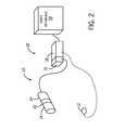
- FIG. 2illustrates an alternate embodiment of the exemplary tracking system implementing certain aspects of the present technique
- FIG. 3illustrates an embodiment of at least one receiver and at least one transmitter in accordance with certain aspects of the present technique
- FIG. 4illustrates another embodiment of at least one receiver and at least one transmitter in accordance with certain aspects of the present technique
- FIG. 5is a flowchart of a method of electromagnetic tracking in accordance with certain aspects of the present technique
- FIG. 6illustrates an embodiment of the at least one receiver including a scalar-magnetometer in accordance with certain aspects of the present technique
- FIG. 7is a flowchart of a method of electromagnetic tracking with the at least one receiver including a scalar-magnetometer in accordance with certain aspects of the present technique.
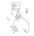
- FIG. 1illustrates a tracking system 10 in accordance with an embodiment of the present technique.
- the tracking system 10includes at least one transmitter 12 , at least one receiver 14 , tracker electronics 15 , a drive unit 16 , a processor 18 , a user interface 20 , a current source 22 , and an instrument 24 .
- the transmitter 12includes a magnetic field source that can be employed to generate a magnetic field.
- the at least one transmitter 12may include an electromagnet that generates the desired magnetic field (e.g., radio frequency (RF) magnetic field).
- the magnetic fieldmay be of sufficient magnitude to be sensed by a complementary device, such as the at least one receiver 14 .
- the at least one transmitter 12includes a single dipole coil.
- the at least one transmitter 12may include a single dipole coil that is about 8 mm long and about 1.7 mm in diameter, with 7700 turns of American Wire Gauge (AWG) wire formed around a ferromagnetic core that is about 8 mm long and about 0.5 mm in diameter.
- AMGAmerican Wire Gauge
- a single magnetic fieldis generated with a magnitude moment vector generally normal to the coil (e.g., along its axis) and having a frequency that is approximately the same as the frequency of the current driving the coil.
- the at least one transmitter 12 in an electromagnetic tracking systemis generally supplied with a sine wave current waveform having a frequency between about 8 kHz and about 40 kHz.
- the at least one transmitter 12generates magnetic fields having frequencies between about 8 kHz and about 40 kHz.
- the at least one transmitter 12may be supplied with frequencies between about 1 Hz to about 8 kHz.
- the at least one transmitter 12may include a plurality (e.g., more than one) of the coils.
- the at least one transmitter 12may be formed from three co-located orthogonal quasi-dipole coils (e.g., a coil-trio). When the coil-trio is energized, each coil generates a magnetic field. As a result, the coil-trio may be employed to generate three magnetic fields having magnitude vectors that are co-located and orthogonal to one another.
- the at least one transmitter 12may include a single dipole coil, a plurality of dipole coils, a coil-trio, a plurality of coil-trios, and the like, or a combination thereof.
- the at least one transmitter 12includes a wireless configuration. In other words, the at least one transmitter 12 does not have a wired connection to various components of the tracking system 10 (e.g., the tracker electronics 15 ). In one embodiment, as discussed in further detail below, the at least one transmitter 12 may include an integral current source 20 (e.g., oscillator). Further, the system 10 may employ processing specifically suited for tracking the at least one transmitter 12 in a wireless configuration.
- the at least one transmitter 12may include an integral current source 20 (e.g., oscillator).
- the system 10may employ processing specifically suited for tracking the at least one transmitter 12 in a wireless configuration.
- the at least one transmitter 12includes a plurality of transmitters.
- the at least one transmitter 12may include an array of transmitters and/or transmitter coils.
- the at least one transmitter 12may include a single transmitter and/or transmitter coil.
- the arrangement and placement of the at least one transmitter 12may be varied to accommodate specific applications.
- the at least one transmitter 12may include a single transmitter or an array of transmitters arranged in a single plane.
- the system 10includes the at least one receiver 14 .
- the at least one receiver 14is configured to sense (e.g., receive) the magnetic field(s) generated by the at least one transmitter 12 .
- the generated magnetic fieldmay induce a response (e.g., a current and a voltage) into the at least one receiver 14 .
- the responseincludes current induced across the at least one receiver 14 that is indicative of the magnetic field between the at least one transmitter 12 and the at least one receiver 14 .
- the magnetic fieldmay be associated with the distance between the at least one transmitter 12 and the at least one receiver 14 .
- the at least one receiver 14may transmit a signal indicative of the magnetic field that can be processed to determine the magnetic field and the distance between the at least one transmitter 12 and at least one receiver 14 .
- the at least one receiver 14includes a scalar-magnetometer.
- the at least one receiver 14may include an atomic-resonance magnetometer.
- the atomic-resonance magnetometermay include rubidium, potassium, cesium, or the like.
- the at least one receiver 14may include an Overhauser magnetometer.
- the at least one receiver 14may include a SERF (spin-exchange relation-free) magnetometer.
- SERFspin-exchange relation-free magnetometer.
- each of the previously discussed scalar-magnetometersmay provide high sensitivity.
- an optically-pumped cesium vapor magnetometeris a highly sensitive (0.004 nT/ ⁇ Hz) and accurate device. Overhauser magnetometers may achieve 0.01 nT/ ⁇ Hz noise levels.
- SERF atomic magnetometers containing potassium vaporoperate similarly to the cesium magnetometers described above yet can reach sensitivities lower than 1 fT/ ⁇ Hz.
- the at least one receiver 14may include a miniature atomic-resonance magnetometer.
- Miniature atomic-resonance magnetometersmay include a form factor that is conducive to placement of the atomic-resonance magnetometers into medical devices.
- One embodimentmay include coupling the at least one receiver 14 into the housing of a guidewire or a catheter, for instance.
- the magnetic field between the at least one transmitter 12 and the at least one receiver 14can be measured regardless as to their mechanical relationship to one another.
- the positions of the at least one transmitter 12 and the at least one receiver 14may be swapped (e.g., reversed).
- the at least one receiver 14may be coupled to the instrument 24 , and the at least one transmitter 12 may be located separate from the instrument 24 .
- the magnetic fieldmay be generated from the at least one transmitter 12 separate from the instrument 24 , and received by the at least one receiver 14 proximate to the instrument 24 (e.g., a guidewire or catheter).
- the system 10further includes tracker electronics 15 including a drive unit 16 , the processor 18 , and the user interface 20 .
- the drive unit 16may be configured to provide a drive current (via a cable) to the at least one transmitter 12 .
- the drive currentmay include a periodic waveform with a given frequency (e.g., a sine wave), for instance.
- the current across a coil of the at least one transmitter 12may generate a magnetic field at the same frequency as the drive current.
- the at least one transmitter 12 of the tracking system 10may be supplied with sinewave current waveforms having frequencies between about 8 kHz and about 40 kHz and, thus, generate magnetic fields having frequencies between about 8 kHz and about 40 kHz.
- the drive unit 16is integral to the processor 18 ; however, in other embodiments, the drive unit 16 may include a unit that is separate from the processor 18 .
- the drive unit 16may include the current source 22 , such as a battery and/or an oscillator, which is integral to the instrument 24 and/or the at least one transmitter 12 .
- the tracker electronics 15also include the processor 18 .
- the processor 18may include, for example, a digital signal processor, a CPU, or the like.
- signals indicative of the magnetic fields sensed by the at least one receiver 14are output to the processor 18 via a cable.
- the processor 18may track the orientation and position of the at least one transmitter 12 based on the signals transmitted from the at least one receiver 14 .
- the at least one receiver 14may produce output signals that are indicative of the magnetic field between the at least one transmitter 12 and the at least one receiver 14 , and the processor 18 may process the magnetic field measurements to triangulate the position of the at least one transmitter 12 and the at least one receiver 14 .
- processingmay selectively filter each magnetic field out of the signal.
- a single drive current of a given frequencymay be sufficient to identify the magnetic field. This is true because only a single transmitting coil is generating a magnetic field.
- the at least one transmitter 12e.g., a coil-trio
- the at least one receiver 14may sense the multiple magnetic fields simultaneously. As a result, a single combined signal from the at least one receiver 14 may be transmitted to the processor 18 .
- the frequency of each of the generated magnetic fieldsmay be varied. Due the variations in frequency, processing can isolate the signals between each respective at least one transmitter 12 and each of the at least one receiver 14 . Thereby, the system may determine the relative position and/or orientation of the at least one transmitter 12 and the at least one receiver 14 .
- the at least one transmitter 12may be electrically coupled to the processor 18 and the at least one receiver 14 . Accordingly, in a wired configuration, the measured phases of the waveforms driving each coil of the at least one transmitter 12 may be known.
- the source of the drive current waveformse.g., the drive unit 16
- the processor 18may “know” the phases of the currents driving the at least one transmitter 12 and can parse out each signal indicative of the given phases and frequencies from the combined signal transmitted by the at least one receiver 14 .
- the processor 18may implement any suitable algorithms to establish the position and/or orientation of the at least one transmitter 12 relative to the at least one receiver 14 .
- the at least one transmitter 12may not have “known” phases of the current waveforms.
- the wireless at least one transmitter 12may be driven by the current source 22 , such as an oscillator, coupled to the at least one transmitter 12 .
- the current source 22may generate each of the current waveforms independent from the processor 18 (i.e., the processor 18 does not have feedback or control relating to the phase of the two currents).
- the at least one transmitter 12may include a standalone device having a current source 22 that is generating magnetic fields independent of the processor 18 .
- the processor 18may incorporate additional considerations in processing to resolve the position and orientation of the at least one transmitter 12 (e.g., identify the phases of the current waveforms generated across at least one coil of the at least one transmitter 12 ).
- the tracker electronics 15also include a user interface 20 .
- the system 10may include a monitor to display the determined position and orientation of a tracked object.
- the user interface 20may include additional devices to facilitate the exchange of data between the tracking system 10 and the user.
- the user interface 20may include a keyboard, mouse, printers or other peripherals. While the processor 18 and the user interface 20 may be separate devices, in certain embodiments, the processor 18 and the user interface 20 may be provided as a single unit.
- the at least one transmitter 12is coupled to the instrument 24 . Accordingly, the tracking system 10 may be employed to track the position of the instrument 24 relative to the at least one receiver 14 and the at least one transmitter 12 .
- the instrument 24may include a catheter, a drill, a guide wire, an endoscope, a laparoscope, a biopsy needle, an ablation device or other similar devices.
- an embodiment of the at least one receiver 14may include a scalar-magnetometer.
- scalar-magnetometersintrinsically measure the magnitude of the magnetic field, but not the direction of the magnetic field. In other words, scalar-magnetometers measure the total strength of the magnetic field to which they are subjected, but do not necessarily provide an indication of the direction of the magnetic field. In operation, scalar-magnetometers are immersed in the earth's magnetic field and, thus, are sensitive to the magnitude of the vector sum of the earth's field and any additional magnetic fields (e.g., the magnetic field generated by the at least one transmitter 12 ).
- the earth's magnetic fieldmay be much larger than the magnetic field generated by the at least one transmitter 12 and only the component of the at least one transmitter's field parallel to the earth's magnetic field contributes to the overall magnitude of the magnetic field.
- the at least one receiver 14 having a single scalar-magnetometerwill respond the same as a receiver having a single coil, except the sensed orientation of the at least one receiver 14 is determined by the direction of the earth's magnetic field rather than the mechanical orientation of the at least one receiver 14 . Accordingly, at least one receiver 14 having the single scalar-magnetometer can be employed to track the position, but not the orientation of the at least one receiver 14 .
- the tracking system 10may employ various arrangements of the at least one transmitter 12 and the at least one receivers 14 employing a scalar-magnetometer.
- the at least one receiver 14may include a single scalar-magnetometer and the at least one transmitter 12 may include one or more transmitters. Accordingly, the at least one receiver 14 may sense each of the magnetic fields generated by each of the at least one transmitters 12 . As will be appreciated, processing may determine the position of the at least one receiver 14 by comparing the ratios of the sensed magnetic fields to triangulate the relative positions of the at least one transmitter 12 and the at least one receiver 14 , as discussed previously. However, due to the inability of the scalar-magnetometer to indicate the direction of the magnitude vector, the orientation of the at least one receiver 14 may not be determined.
- the at least one receiver 14may include more than one scalar-magnetometer.
- FIG. 3illustrates an embodiment of the at least one receiver 14 including two scalar-magnetometers.
- the at least one receiver 14includes a first scalar-magnetometer 26 and a second scalar-magnetometer 28 .
- the scalar-magnetometers 26 and 28are spaced a given distance 30 from one another.
- processingmay determine the position of each of the scalar-magnetometers 26 and 28 by comparing the ratios of the sensed magnetic fields, as discussed previously.
- processingmay also resolve the azimuth, the elevation and the position of the at least one receiver 14 , but not the roll.
- the tracking system 10may track the position, azimuth, and elevation of the instrument 24 .
- FIG. 4illustrates an embodiment of the at least one receiver 14 including three scalar-magnetometers.
- the at least one receiver 14includes the first scalar-magnetometer 26 , the second scalar-magnetometer 28 , and a third scalar magnetometer 32 .
- the scalar magnetometers 26 , 28 , and 32are spaced apart from one another in a plane 34 .
- processingmay determine the position of each of the scalar-magnetometers 26 , 28 , and 32 by comparing the ratios of the sensed magnetic fields, as discussed previously.
- processingmay resolve the position and the orientation (e.g., the azimuth, the elevation, the roll) of the at least one receiver 14 .
- the tracking system 10may track the position, azimuth, and elevation of the instrument 24 .
- embodiments of the at least one receiver 14may include any number of scalar-magnetometers.
- an embodimentmay include four or more scalar-magnetometers.
- each of the scalar-magnetometersmay be co-planar.
- the scalar-magnetometersmay not be co-planar.
- increasing the number of scalar-magnetometers employed in the at least one receiver 14may enable processing to more accurately determine the position and/or orientation of the at least one receiver 14 , and any devices (e.g., the instrument 24 ) coupled thereto.
- Embodimentsmay also include a plurality of the at least one receivers 14 that are each formed from any number of scalar-magnetometers.
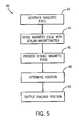
- FIG. 5illustrates a method of tracking using scalar-magnetometers in accordance with an embodiment of the present technique.
- the method 40includes generating at least one magnetic field as illustrated at block 42 .
- Generating at least one magnetic fieldmay include energizing the at least one transmitter 12 , as discussed previously.
- the drive unit 16 and/or the current source 22may drive a current across a single dipole coil, a plurality of dipole coils, a coil-trio, and/or a plurality of coil-trios, of the at least one transmitter 12 .
- the drive current and the generated at least one magnetic fieldmay include differing frequencies, magnitudes and phases to accommodate the specific tracking application.
- the method 40also includes sensing the at least one magnetic field with a scalar-magnetometer, as illustrated at block 44 .
- the generated magnetic field(block 42 ) may be sensed by the at least one receiver 14 including the scalar-magnetometer.
- the at least one receiver 14may include one or more scalar-magnetometers 26 , 28 , and 32 , as discussed previously.
- sensing the at least one magnetic field(block 44 ) may include transmitting a signal indicative of the sensed magnetic field from the at least one receiver 14 to the processor 18 .
- the method 40further includes processing the sensed magnetic field, as illustrated at block 46 .
- processing the sensed magnetic fieldincludes receiving a signal indicative of the sensed magnetic field (block 44 ).
- Processingmay also include conditioning the signals and/or determining the magnetic field between the each of the at least one transmitters 12 and the at least one receivers 14 .
- the method 40includes determining a position, as illustrated at block 48 .
- determining a positionmay include determining the relative positions of the at least one transmitter 12 , and the at least one receivers 14 based on the signals sensed by the at least one receiver 14 including scalar-magnetometers.
- determining the magnetic fieldsmay enable the system to compare the ratios of the magnetic fields to triangulate the position of the at least one transmitter 12 and the at least one receiver 14 relative to one another.
- determining a positionmay also include determining the position of the instrument 24 .
- the determined position of the at least one transmitter 12 and the at least one receiver 14may be translated to provide a relative position of the instrument 24 . Further, determining the position may also include determining the orientation of the at least one transmitter 12 and the at least one receiver 14 relative to one another. For example, where the system includes a plurality of scalar-magnetometers 26 , 28 , and 32 , processing may be capable of resolving the relative positions and/or orientations of the at least one transmitter 12 and the at least one receiver 14 .
- the method 40also includes outputting a tracked position, as illustrated at block 50 .
- outputting a tracked positionincludes providing the position and/or the orientation of the at least one transmitter 12 , the at least one receiver 14 , and/or the instrument 24 to the user interface 20 .
- the user interface 20may output a value, an image with an overlay, or other indication of position and/or orientation.
- an embodimentmay include transmitting the position and orientation data to a file, a data base, subsequent processing, or the like.
- trackingmay include repetitions of the above discussed method 40 to enable the system 10 to continually determine the positions and/or orientation of the at least one receiver 14 , the at least one transmitter 12 , and/or the instrument 24 . Accordingly, each of the steps of the method 40 may be accomplished in varying orders, or even simultaneously.
- the tracking system 10may employ a configuration of the at least one receiver 14 that enables changing the direction of the sensitivity of the scalar-magnetometer.
- magnetic field sourcese.g., coils
- the scalar-magnetometermay be employed around the scalar-magnetometer and energized to change the direction of the static field (e.g., the magnetic field of the environment, including the earth's magnetic field) applied to the scalar-magnetometer.
- coils surrounding the scalar-magnetometercan be energized to generate magnetic fields that offset the earth's magnetic field or other surrounding magnetic fields.
- the direction of the scalar magnetometer's sensitivitycan be controlled.
- offsetting the earth's magnetic fieldmay enable the scalar-magnetometer to be sensitive to a component of a magnetic field magnitude vector that would otherwise be insignificant when compared to the earth's magnetic field in another direction.
- FIG. 6illustrates an embodiment of the at least one receiver 14 having coils that generate at least one additional magnetic field to vary the sensitivity of a scalar-magnetometer.
- the at least one receiver 14includes a scalar-magnetometer 52 surrounded by a coil-trio 54 including three co-located orthogonal quasi-dipole coils.
- the coil-trio 54includes a first coil 56 , a second coil 58 and a third coil 60 having axes that are generally orthogonal to one another.
- the scalar-magnetometer 52is disposed in the center of the coil-trio 54 .
- Driving a current across the first coil 56 , the second coil 58 and the third coil 60generates magnetic fields having a first magnitude vector 62 , a second magnitude vector 64 , and a third magnitude vector 66 , respectively.
- the magnitude vectors 62 , 64 , and 66 of the magnetic fields generated by each of the first, second and third coils 56 , 58 , and 60can be varied to offset the earth's magnetic field and surrounding magnetic fields (e.g., electronics) and provide sensitivity of the scalar-magnetometer 52 in a desired direction.
- the three coils 56 , 58 , and 60may be driven with a current to offset the effects of the earth's magnetic field to increase the sensitivity of the scalar magnetometer in another direction.
- the three coils 56 , 58 , and 60may be driven at three different time intervals with pulsed direct current (DC) fields to give approximately orthogonal sensitivities at the different time intervals.
- the system 10can measure the magnetic fields sensed by the scalar-magnetometer 52 of the at least one receiver 14 during the first time interval, the second time interval, and the third time interval.
- the system 10may have at least three field measurements from the at least one receiver 14 .
- the systemmay take nine field measurements (e.g., three measurements during each of the three time intervals).
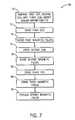
- FIG. 7is a flowchart illustrating a method 68 of tracking using a scalar-magnetometer surrounded by coils that are configured to manipulate the sensitivity of a scalar-magnetometer.
- the method 68includes disposing a first, second, and third coil about the scalar-magnetometer, as illustrated at block 70 .
- disposing a first, second, and third coil about the scalar-magnetometer (block 70 )may include disposing the coil-trio 54 about the scalar-magnetometer 52 as discussed with regard to FIG. 6 .
- the first coil 56 , the second coil 58 , and the third coil 60may be co-located orthogonal quasi-dipole coils.
- any number of coilsmay be disposed about various locations surrounding the scalar-magnetometer 52 .
- Another embodimentmay include, a single coil or any number of coils disposed proximate to the scalar-magnetometer 52 that are configured to generate a magnetic field that can be sensed by the scalar-magnetometer 52 and may offset at least a portion of the static magnetic field.
- the method 68also includes driving the first coil, as illustrated at block 72 .
- driving the first coilmay include driving a current across the first coil 56 of the coil-trio 54 disposed about the scalar-magnetometer 52 .
- driving the currentmay cause the first coil 56 to generate a magnetic field that offsets at least a portion of the static magnetic field experienced by the scalar-magnetometer 52 .
- the currentmay be driven across the first coil (block 72 ) only during a first time interval.
- the currentmay include a pulsed DC signal driven across the first coil 56 and configured to generate a generally constant magnitude magnetic field during the duration of the pulsed DC signal.
- the constant magnitude magnetic fieldoffsets at least a portion of the static magnetic field.
- the magnitude of the magnetic fieldmay be of sufficient magnitude to cancel out the component of the earth's DC magnetic field in the opposite direction of the first magnitude vector 62 that would otherwise be sensed by the scalar-magnetometer 52 .
- the method 68also includes sensing the first magnetic fields, as illustrated at block 74 .
- the method 68includes sensing the first magnetic fields (block 74 ) received by the scalar-magnetometer 52 during the period when the system 10 is driving the first coil (block 72 ).
- the system 10may measure the magnetic fields at the scalar-magnetometer 52 during the first time interval. Accordingly, the measured magnetic field may include each of the magnetic fields generated from the at least one transmitter 12 , and the first coil 56 .
- the first magnetic fieldsmay include each of the magnetic fields generated by the at least one transmitter 12 .
- the first magnetic fieldsinclude each of the three fields generated by the at least one transmitter 12 .
- the at least one transmitter 12includes a single dipole coil generating a single magnetic field
- the first magnetic fieldsmay include the single magnetic field.
- the at least one receiver 14may transmit a signal that is indicative of the measured magnetic fields generated by the at least one transmitter 12 during the first time interval (e.g., when at least a portion of the static field has been offset and the scalar-magnetometer has increased sensitivity in a first direction).
- the method 68includes driving the second coil, as illustrated at block 76 .
- driving the second coil (block 76 )may include driving a current across the second coil 58 of the coil-trio 54 disposed about the scalar-magnetometer 52 . Further, the current may be driven across the second coil (block 76 ) during a second time interval. For example, similar to driving the first coil (block 72 ) the pulsed DC signal may be driven during the second time interval, such that the DC pulse provides a constant magnitude magnetic field during the second time period.
- the method 68also includes sensing the second magnetic fields, as illustrated at block 78 .
- the method 68includes sensing the second magnetic fields (block 76 ) received by the scalar-magnetometer 52 during the period when the system 10 is driving the second coil (block 76 ).
- the at least one receiver 14may transmit a signal that is indicative of the measured magnetic fields during the second time interval (e.g., when at least a portion of the static field has been offset and the scalar-magnetometer has increased sensitivity in a second direction).
- the method 68includes driving the third coil, as illustrated at block 80 .
- driving the second coil (block 80 )may include driving a current across the third coil 58 of the coil-trio 54 disposed about the scalar-magnetometer 52 . Further, the current may be driven across the third coil (block 80 ) during a third time interval. For example, similar to driving the first and second coil (blocks 72 and 76 ) the pulsed DC signal may be driven during the second time interval, such that the DC pulse provides a constant magnitude magnetic field during the third time period.
- the method 68also includes sensing the third magnetic field, as illustrated at block 82 .
- the method 68includes sensing the third magnetic fields (block 82 ) received by the scalar-magnetometer 52 during the period when the system 10 is driving the third coil (block 80 ).
- the at least one receiver 14may transmit a signal that is indicative of the measured magnetic fields during the third time interval (e.g., when at least a portion of the static field has been offset and the scalar-magnetometer has increased sensitivity in a third direction).
- the method 68includes processing the sensed magnetic fields, as illustrated at block 84 .
- the sensed magnetic fieldsmay include the first, second and third sensed magnetic fields (blocks 74 , 78 and 82 ).
- Each of the magnetic fields sensedmay be processed to account for the magnetic field in a plurality of directions.
- driving the first coil (block 72 )may generate a magnetic field having the first magnitude vector 62 that offsets the earth's magnetic field in the opposite direction of the first magnitude vector 62 .
- the scalar-magnetometer 52may have increased sensitivity in the direction of the magnitude vector 62 .
- processingmay use each of the measurements taken during the first, second, and third time intervals to obtain a measurement of the sensed magnetic fields with sensitivity in the plurality of directions, as opposed to a single magnetic field measurement of magnitude.
- the plurality of coilsmay be employed to offset the earth's magnetic field such that the scalar-magnetometer 54 may have sensitivity in at least one direction based on the magnetic fields generated by the coils.
- processingmay determine orientation of the at least one receiver 14 relative to the at least one transmitter 12 . Further, in an embodiment that includes an arrangement wherein the at least one transmitter 12 includes a coil-trio (ISCA), processing may consider nine field measurements (e.g., three measurements during each of the three time intervals) in the determination of relative positions and orientations of the at least one transmitter 12 , and the at least one receiver 14 .
- ISCAcoil-trio
Landscapes
- Physics & Mathematics (AREA)
- Nonlinear Science (AREA)
- Engineering & Computer Science (AREA)
- General Engineering & Computer Science (AREA)
- General Physics & Mathematics (AREA)
- Measurement Of Length, Angles, Or The Like Using Electric Or Magnetic Means (AREA)
- Measuring Magnetic Variables (AREA)
Abstract
Description
Claims (5)
Priority Applications (1)
| Application Number | Priority Date | Filing Date | Title |
|---|---|---|---|
| US11/860,649US7834621B2 (en) | 2007-09-25 | 2007-09-25 | Electromagnetic tracking employing scalar-magnetometer |
Applications Claiming Priority (1)
| Application Number | Priority Date | Filing Date | Title |
|---|---|---|---|
| US11/860,649US7834621B2 (en) | 2007-09-25 | 2007-09-25 | Electromagnetic tracking employing scalar-magnetometer |
Publications (2)
| Publication Number | Publication Date |
|---|---|
| US20090079426A1 US20090079426A1 (en) | 2009-03-26 |
| US7834621B2true US7834621B2 (en) | 2010-11-16 |
Family
ID=40470944
Family Applications (1)
| Application Number | Title | Priority Date | Filing Date |
|---|---|---|---|
| US11/860,649Active2027-11-10US7834621B2 (en) | 2007-09-25 | 2007-09-25 | Electromagnetic tracking employing scalar-magnetometer |
Country Status (1)
| Country | Link |
|---|---|
| US (1) | US7834621B2 (en) |
Cited By (5)
| Publication number | Priority date | Publication date | Assignee | Title |
|---|---|---|---|---|
| US20110298457A1 (en)* | 2010-06-02 | 2011-12-08 | Halliburton Energy Services, Inc. | Downhole orientation sensing with nuclear spin gyroscope |
| US20110319751A1 (en)* | 2007-05-31 | 2011-12-29 | General Electric Company | Dynamic reference method and system for use with surgical procedures |
| US8421455B1 (en)* | 2008-09-26 | 2013-04-16 | Southwest Sciences Incorporated | Pulsed free induction decay nonlinear magneto-optical rotation apparatus |
| US9869731B1 (en) | 2014-03-31 | 2018-01-16 | The Regents Of The University Of California | Wavelength-modulated coherence pumping and hyperfine repumping for an atomic magnetometer |
| US9891291B2 (en) | 2011-08-01 | 2018-02-13 | Soreq Nuclear Research Center | Magnetic tracking system |
Families Citing this family (91)
| Publication number | Priority date | Publication date | Assignee | Title |
|---|---|---|---|---|
| US8581580B2 (en) | 2010-06-02 | 2013-11-12 | Halliburton Energy Services, Inc. | Downhole orientation sensing with nuclear spin gyroscope |
| US10048073B2 (en)* | 2011-11-07 | 2018-08-14 | Raytheon Company | Beacon-based geolocation using a low frequency electromagnetic field |
| US9983276B2 (en)* | 2012-06-25 | 2018-05-29 | Halliburton Energy Services, Inc. | Downhole all-optical magnetometer sensor |
| US9638821B2 (en) | 2014-03-20 | 2017-05-02 | Lockheed Martin Corporation | Mapping and monitoring of hydraulic fractures using vector magnetometers |
| US9853837B2 (en) | 2014-04-07 | 2017-12-26 | Lockheed Martin Corporation | High bit-rate magnetic communication |
| US10168393B2 (en) | 2014-09-25 | 2019-01-01 | Lockheed Martin Corporation | Micro-vacancy center device |
| US9910104B2 (en) | 2015-01-23 | 2018-03-06 | Lockheed Martin Corporation | DNV magnetic field detector |
| US9551763B1 (en) | 2016-01-21 | 2017-01-24 | Lockheed Martin Corporation | Diamond nitrogen vacancy sensor with common RF and magnetic fields generator |
| US9845153B2 (en) | 2015-01-28 | 2017-12-19 | Lockheed Martin Corporation | In-situ power charging |
| US9829545B2 (en) | 2015-11-20 | 2017-11-28 | Lockheed Martin Corporation | Apparatus and method for hypersensitivity detection of magnetic field |
| US9910105B2 (en) | 2014-03-20 | 2018-03-06 | Lockheed Martin Corporation | DNV magnetic field detector |
| US10012704B2 (en) | 2015-11-04 | 2018-07-03 | Lockheed Martin Corporation | Magnetic low-pass filter |
| US10241158B2 (en) | 2015-02-04 | 2019-03-26 | Lockheed Martin Corporation | Apparatus and method for estimating absolute axes' orientations for a magnetic detection system |
| WO2015157290A1 (en) | 2014-04-07 | 2015-10-15 | Lockheed Martin Corporation | Energy efficient controlled magnetic field generator circuit |
| CN105882987B (en)* | 2014-12-23 | 2017-12-19 | 中国科学院遥感与数字地球研究所 | A kind of gondola for hanging aviation superconductive magnetometer |
| WO2016118756A1 (en) | 2015-01-23 | 2016-07-28 | Lockheed Martin Corporation | Apparatus and method for high sensitivity magnetometry measurement and signal processing in a magnetic detection system |
| WO2016190909A2 (en)* | 2015-01-28 | 2016-12-01 | Lockheed Martin Corporation | Magnetic navigation methods and systems utilizing power grid and communication network |
| GB2551090A (en) | 2015-02-04 | 2017-12-06 | Lockheed Corp | Apparatus and method for recovery of three dimensional magnetic field from a magnetic detection system |
| WO2017039747A1 (en)* | 2015-09-04 | 2017-03-09 | Lockheed Martin Corporation | Magnetic wake detector |
| WO2017087013A1 (en) | 2015-11-20 | 2017-05-26 | Lockheed Martin Corporation | Apparatus and method for closed loop processing for a magnetic detection system |
| WO2017095454A1 (en) | 2015-12-01 | 2017-06-08 | Lockheed Martin Corporation | Communication via a magnio |
| US10196927B2 (en)* | 2015-12-09 | 2019-02-05 | General Electric Company | System and method for locating a probe within a gas turbine engine |
| US10196922B2 (en)* | 2015-12-09 | 2019-02-05 | General Electric Company | System and method for locating a probe within a gas turbine engine |
| WO2017123261A1 (en) | 2016-01-12 | 2017-07-20 | Lockheed Martin Corporation | Defect detector for conductive materials |
| GB2562958A (en) | 2016-01-21 | 2018-11-28 | Lockheed Corp | Magnetometer with a light emitting diode |
| WO2017127090A1 (en) | 2016-01-21 | 2017-07-27 | Lockheed Martin Corporation | Higher magnetic sensitivity through fluorescence manipulation by phonon spectrum control |
| WO2017127079A1 (en) | 2016-01-21 | 2017-07-27 | Lockheed Martin Corporation | Ac vector magnetic anomaly detection with diamond nitrogen vacancies |
| WO2017127098A1 (en) | 2016-01-21 | 2017-07-27 | Lockheed Martin Corporation | Diamond nitrogen vacancy sensed ferro-fluid hydrophone |
| WO2017127096A1 (en) | 2016-01-21 | 2017-07-27 | Lockheed Martin Corporation | Diamond nitrogen vacancy sensor with dual rf sources |
| EP3405603A4 (en) | 2016-01-21 | 2019-10-16 | Lockheed Martin Corporation | Diamond nitrogen vacancy sensor with circuitry on diamond |
| WO2017127094A1 (en) | 2016-01-21 | 2017-07-27 | Lockheed Martin Corporation | Magnetometer with light pipe |
| US10408890B2 (en) | 2017-03-24 | 2019-09-10 | Lockheed Martin Corporation | Pulsed RF methods for optimization of CW measurements |
| US10571530B2 (en) | 2016-05-31 | 2020-02-25 | Lockheed Martin Corporation | Buoy array of magnetometers |
| US10345396B2 (en) | 2016-05-31 | 2019-07-09 | Lockheed Martin Corporation | Selected volume continuous illumination magnetometer |
| US10359479B2 (en) | 2017-02-20 | 2019-07-23 | Lockheed Martin Corporation | Efficient thermal drift compensation in DNV vector magnetometry |
| US10527746B2 (en) | 2016-05-31 | 2020-01-07 | Lockheed Martin Corporation | Array of UAVS with magnetometers |
| US10345395B2 (en) | 2016-12-12 | 2019-07-09 | Lockheed Martin Corporation | Vector magnetometry localization of subsurface liquids |
| US10274550B2 (en) | 2017-03-24 | 2019-04-30 | Lockheed Martin Corporation | High speed sequential cancellation for pulsed mode |
| US10281550B2 (en) | 2016-11-14 | 2019-05-07 | Lockheed Martin Corporation | Spin relaxometry based molecular sequencing |
| US10338163B2 (en) | 2016-07-11 | 2019-07-02 | Lockheed Martin Corporation | Multi-frequency excitation schemes for high sensitivity magnetometry measurement with drift error compensation |
| US10371765B2 (en) | 2016-07-11 | 2019-08-06 | Lockheed Martin Corporation | Geolocation of magnetic sources using vector magnetometer sensors |
| US20170343621A1 (en) | 2016-05-31 | 2017-11-30 | Lockheed Martin Corporation | Magneto-optical defect center magnetometer |
| US10677953B2 (en) | 2016-05-31 | 2020-06-09 | Lockheed Martin Corporation | Magneto-optical detecting apparatus and methods |
| US10145910B2 (en) | 2017-03-24 | 2018-12-04 | Lockheed Martin Corporation | Photodetector circuit saturation mitigation for magneto-optical high intensity pulses |
| US10330744B2 (en) | 2017-03-24 | 2019-06-25 | Lockheed Martin Corporation | Magnetometer with a waveguide |
| US10317279B2 (en) | 2016-05-31 | 2019-06-11 | Lockheed Martin Corporation | Optical filtration system for diamond material with nitrogen vacancy centers |
| US10228429B2 (en) | 2017-03-24 | 2019-03-12 | Lockheed Martin Corporation | Apparatus and method for resonance magneto-optical defect center material pulsed mode referencing |
| US10371760B2 (en) | 2017-03-24 | 2019-08-06 | Lockheed Martin Corporation | Standing-wave radio frequency exciter |
| US10338164B2 (en) | 2017-03-24 | 2019-07-02 | Lockheed Martin Corporation | Vacancy center material with highly efficient RF excitation |
| US10379174B2 (en) | 2017-03-24 | 2019-08-13 | Lockheed Martin Corporation | Bias magnet array for magnetometer |
| US10459041B2 (en) | 2017-03-24 | 2019-10-29 | Lockheed Martin Corporation | Magnetic detection system with highly integrated diamond nitrogen vacancy sensor |
| CN116725667A (en) | 2017-06-28 | 2023-09-12 | 奥瑞斯健康公司 | System for providing positioning information and method for positioning an instrument within an anatomical structure |
| WO2019005696A1 (en) | 2017-06-28 | 2019-01-03 | Auris Health, Inc. | Electromagnetic distortion detection |
| CN111133656A (en)* | 2017-07-20 | 2020-05-08 | Tdk株式会社 | Primary assembly for wireless power transfer system, positioning system, and method of determining distance between primary and secondary assemblies |
| US10489896B2 (en) | 2017-11-14 | 2019-11-26 | General Electric Company | High dynamic range video capture using variable lighting |
| US10488349B2 (en) | 2017-11-14 | 2019-11-26 | General Electric Company | Automated borescope insertion system |
| US10775315B2 (en) | 2018-03-07 | 2020-09-15 | General Electric Company | Probe insertion system |
| WO2020005460A1 (en)* | 2018-06-25 | 2020-01-02 | Hi Llc | Magnetic field measurement systems and methods of making and using |
| US10976386B2 (en) | 2018-07-17 | 2021-04-13 | Hi Llc | Magnetic field measurement system and method of using variable dynamic range optical magnetometers |
| US11262420B2 (en) | 2018-08-17 | 2022-03-01 | Hi Llc | Integrated gas cell and optical components for atomic magnetometry and methods for making and using |
| US11136647B2 (en) | 2018-08-17 | 2021-10-05 | Hi Llc | Dispensing of alkali metals mediated by zero oxidation state gold surfaces |
| WO2020040882A1 (en) | 2018-08-20 | 2020-02-27 | Hi Llc | Magnetic field shaping components for magnetic field measurement systems and methods for making and using |
| US10627460B2 (en) | 2018-08-28 | 2020-04-21 | Hi Llc | Systems and methods including multi-mode operation of optically pumped magnetometer(s) |
| WO2020060652A1 (en) | 2018-09-18 | 2020-03-26 | Hi Llc | Dynamic magnetic shielding and beamforming using ferrofluid for compact magnetoencephalography (meg) |
| US11370941B2 (en) | 2018-10-19 | 2022-06-28 | Hi Llc | Methods and systems using molecular glue for covalent bonding of solid substrates |
| US11307268B2 (en) | 2018-12-18 | 2022-04-19 | Hi Llc | Covalently-bound anti-relaxation surface coatings and application in magnetometers |
| US11294008B2 (en) | 2019-01-25 | 2022-04-05 | Hi Llc | Magnetic field measurement system with amplitude-selective magnetic shield |
| US11022658B2 (en) | 2019-02-12 | 2021-06-01 | Hi Llc | Neural feedback loop filters for enhanced dynamic range magnetoencephalography (MEG) systems and methods |
| EP3948317A1 (en) | 2019-03-29 | 2022-02-09 | Hi LLC | Integrated magnetometer arrays for magnetoencephalography (meg) detection systems and methods |
| US11269027B2 (en) | 2019-04-23 | 2022-03-08 | Hi Llc | Compact optically pumped magnetometers with pump and probe configuration and systems and methods |
| US11698419B2 (en) | 2019-05-03 | 2023-07-11 | Hi Llc | Systems and methods for concentrating alkali metal within a vapor cell of a magnetometer away from a transit path of light |
| US11839474B2 (en) | 2019-05-31 | 2023-12-12 | Hi Llc | Magnetoencephalography (MEG) phantoms for simulating neural activity |
| US11131729B2 (en) | 2019-06-21 | 2021-09-28 | Hi Llc | Systems and methods with angled input beams for an optically pumped magnetometer |
| US11415641B2 (en) | 2019-07-12 | 2022-08-16 | Hi Llc | Detachable arrangement for on-scalp magnetoencephalography (MEG) calibration |
| WO2021026143A1 (en) | 2019-08-06 | 2021-02-11 | Hi Llc | Systems and methods having an optical magnetometer array with beam splitters |
| EP4025921A4 (en) | 2019-09-03 | 2023-09-06 | Auris Health, Inc. | DETECTION AND COMPENSATION OF ELECTROMAGNETIC DISTORTION |
| WO2021045953A1 (en) | 2019-09-03 | 2021-03-11 | Hi Llc | Methods and systems for fast field zeroing for magnetoencephalography (meg) |
| US11521792B2 (en)* | 2019-09-16 | 2022-12-06 | Utah State University | Wireless power transfer with active field cancellation using multiple magnetic flux sinks |
| US11474129B2 (en) | 2019-11-08 | 2022-10-18 | Hi Llc | Methods and systems for homogenous optically-pumped vapor cell array assembly from discrete vapor cells |
| US11872042B2 (en) | 2020-02-12 | 2024-01-16 | Hi Llc | Self-calibration of flux gate offset and gain drift to improve measurement accuracy of magnetic fields from the brain using a wearable neural detection system |
| US11801003B2 (en) | 2020-02-12 | 2023-10-31 | Hi Llc | Estimating the magnetic field at distances from direct measurements to enable fine sensors to measure the magnetic field from the brain using a neural detection system |
| US11604236B2 (en) | 2020-02-12 | 2023-03-14 | Hi Llc | Optimal methods to feedback control and estimate magnetic fields to enable a neural detection system to measure magnetic fields from the brain |
| US11980466B2 (en) | 2020-02-12 | 2024-05-14 | Hi Llc | Nested and parallel feedback control loops for ultra-fine measurements of magnetic fields from the brain using a neural detection system |
| US11977134B2 (en) | 2020-02-24 | 2024-05-07 | Hi Llc | Mitigation of an effect of capacitively coupled current while driving a sensor component over an unshielded twisted pair wire configuration |
| WO2021242680A1 (en) | 2020-05-28 | 2021-12-02 | Hi Llc | Systems and methods for recording neural activity |
| WO2021242682A1 (en) | 2020-05-28 | 2021-12-02 | Hi Llc | Systems and methods for recording biomagnetic fields of the human heart |
| US11428756B2 (en) | 2020-05-28 | 2022-08-30 | Hi Llc | Magnetic field measurement or recording systems with validation using optical tracking data |
| US11766217B2 (en) | 2020-05-28 | 2023-09-26 | Hi Llc | Systems and methods for multimodal pose and motion tracking for magnetic field measurement or recording systems |
| US11604237B2 (en) | 2021-01-08 | 2023-03-14 | Hi Llc | Devices, systems, and methods with optical pumping magnetometers for three-axis magnetic field sensing |
| US11803018B2 (en) | 2021-01-12 | 2023-10-31 | Hi Llc | Devices, systems, and methods with a piezoelectric-driven light intensity modulator |
| US12007454B2 (en) | 2021-03-11 | 2024-06-11 | Hi Llc | Devices, systems, and methods for suppressing optical noise in optically pumped magnetometers |
Citations (34)
| Publication number | Priority date | Publication date | Assignee | Title |
|---|---|---|---|---|
| US1450080A (en) | 1919-08-07 | 1923-03-27 | Louis A Hazeltine | Method and electric circuit arrangement for neutralizing capacity coupling |
| US4327498A (en)* | 1980-03-17 | 1982-05-04 | Sperry Corporation | Magnetic compass compensation system |
| US4710708A (en) | 1981-04-27 | 1987-12-01 | Develco | Method and apparatus employing received independent magnetic field components of a transmitted alternating magnetic field for determining location |
| US4814707A (en)* | 1987-06-17 | 1989-03-21 | Texas Instruments Incorporated | Scalar magnetometer with vector capabilities |
| US4849692A (en) | 1986-10-09 | 1989-07-18 | Ascension Technology Corporation | Device for quantitatively measuring the relative position and orientation of two bodies in the presence of metals utilizing direct current magnetic fields |
| US4945305A (en) | 1986-10-09 | 1990-07-31 | Ascension Technology Corporation | Device for quantitatively measuring the relative position and orientation of two bodies in the presence of metals utilizing direct current magnetic fields |
| US5425382A (en) | 1993-09-14 | 1995-06-20 | University Of Washington | Apparatus and method for locating a medical tube in the body of a patient |
| US5558091A (en) | 1993-10-06 | 1996-09-24 | Biosense, Inc. | Magnetic determination of position and orientation |
| US5592939A (en) | 1995-06-14 | 1997-01-14 | Martinelli; Michael A. | Method and system for navigating a catheter probe |
| US5640170A (en) | 1995-06-05 | 1997-06-17 | Polhemus Incorporated | Position and orientation measuring system having anti-distortion source configuration |
| WO1997036192A1 (en) | 1996-03-27 | 1997-10-02 | Paul Scherrer Institut | Device and process for determining position |
| US5676673A (en) | 1994-09-15 | 1997-10-14 | Visualization Technology, Inc. | Position tracking and imaging system with error detection for use in medical applications |
| US5747996A (en)* | 1994-03-09 | 1998-05-05 | U.S. Philips Corporation | Device for determining the spatial position of a sensor element which is displacement relative to a reference element |
| US5782765A (en) | 1996-04-25 | 1998-07-21 | Medtronic, Inc. | Medical positioning system |
| US5829444A (en) | 1994-09-15 | 1998-11-03 | Visualization Technology, Inc. | Position tracking and imaging system for use in medical applications |
| US5913820A (en) | 1992-08-14 | 1999-06-22 | British Telecommunications Public Limited Company | Position location system |
| US6052610A (en)* | 1998-01-09 | 2000-04-18 | International Business Machines Corporation | Magnetic catheter tracker and method therefor |
| US6073043A (en)* | 1997-12-22 | 2000-06-06 | Cormedica Corporation | Measuring position and orientation using magnetic fields |
| US6129668A (en) | 1997-05-08 | 2000-10-10 | Lucent Medical Systems, Inc. | System and method to determine the location and orientation of an indwelling medical device |
| US6172499B1 (en) | 1999-10-29 | 2001-01-09 | Ascension Technology Corporation | Eddy current error-reduced AC magnetic position measurement system |
| US6201387B1 (en) | 1997-10-07 | 2001-03-13 | Biosense, Inc. | Miniaturized position sensor having photolithographic coils for tracking a medical probe |
| US6226547B1 (en) | 1997-11-15 | 2001-05-01 | Roke Manor Research Limited | Catheter tracking system |
| US6246231B1 (en) | 1999-07-29 | 2001-06-12 | Ascension Technology Corporation | Magnetic field permeable barrier for magnetic position measurement system |
| US6269324B1 (en)* | 1998-10-19 | 2001-07-31 | Raytheon Company | Magnetic object tracking based on direct observation of magnetic sensor measurements |
| US6424853B1 (en)* | 1997-10-24 | 2002-07-23 | Hitachi, Ltd. | Magnetic field measurement apparatus |
| US6502031B2 (en) | 2001-03-27 | 2002-12-31 | Mitsubishi Denki Kabushiki Kaisha | Vehicle position recognizing system |
| US6539327B1 (en) | 1997-09-11 | 2003-03-25 | Commissariat A L'energie Atomique | Process for determining the position of a moving object using magnetic gradientmetric measurements |
| US6701179B1 (en) | 1999-10-28 | 2004-03-02 | Michael A. Martinelli | Coil structures and methods for generating magnetic fields |
| US6774624B2 (en) | 2002-03-27 | 2004-08-10 | Ge Medical Systems Global Technology Company, Llc | Magnetic tracking system |
| US20050065433A1 (en)* | 2003-09-24 | 2005-03-24 | Anderson Peter Traneus | System and method for software configurable electromagnetic tracking |
| US20060058604A1 (en) | 2004-08-25 | 2006-03-16 | General Electric Company | System and method for hybrid tracking in surgical navigation |
| US7015859B2 (en) | 2003-11-14 | 2006-03-21 | General Electric Company | Electromagnetic tracking system and method using a three-coil wireless transmitter |
| US20060247511A1 (en) | 2003-07-01 | 2006-11-02 | General Electric Company | Ultra-low frequency electromagnetic tracking system |
| US20070080682A1 (en)* | 2005-10-06 | 2007-04-12 | Assaf Govari | Magnetic sensor assembly |
- 2007
- 2007-09-25USUS11/860,649patent/US7834621B2/enactiveActive
Patent Citations (45)
| Publication number | Priority date | Publication date | Assignee | Title |
|---|---|---|---|---|
| US1450080A (en) | 1919-08-07 | 1923-03-27 | Louis A Hazeltine | Method and electric circuit arrangement for neutralizing capacity coupling |
| US4327498A (en)* | 1980-03-17 | 1982-05-04 | Sperry Corporation | Magnetic compass compensation system |
| US4710708A (en) | 1981-04-27 | 1987-12-01 | Develco | Method and apparatus employing received independent magnetic field components of a transmitted alternating magnetic field for determining location |
| US4849692A (en) | 1986-10-09 | 1989-07-18 | Ascension Technology Corporation | Device for quantitatively measuring the relative position and orientation of two bodies in the presence of metals utilizing direct current magnetic fields |
| US4945305A (en) | 1986-10-09 | 1990-07-31 | Ascension Technology Corporation | Device for quantitatively measuring the relative position and orientation of two bodies in the presence of metals utilizing direct current magnetic fields |
| US4814707A (en)* | 1987-06-17 | 1989-03-21 | Texas Instruments Incorporated | Scalar magnetometer with vector capabilities |
| US6374134B1 (en) | 1992-08-14 | 2002-04-16 | British Telecommunications Public Limited Company | Simultaneous display during surgical navigation |
| US5913820A (en) | 1992-08-14 | 1999-06-22 | British Telecommunications Public Limited Company | Position location system |
| US5425382A (en) | 1993-09-14 | 1995-06-20 | University Of Washington | Apparatus and method for locating a medical tube in the body of a patient |
| US5558091A (en) | 1993-10-06 | 1996-09-24 | Biosense, Inc. | Magnetic determination of position and orientation |
| US5747996A (en)* | 1994-03-09 | 1998-05-05 | U.S. Philips Corporation | Device for determining the spatial position of a sensor element which is displacement relative to a reference element |
| US5803089A (en) | 1994-09-15 | 1998-09-08 | Visualization Technology, Inc. | Position tracking and imaging system for use in medical applications |
| US5676673A (en) | 1994-09-15 | 1997-10-14 | Visualization Technology, Inc. | Position tracking and imaging system with error detection for use in medical applications |
| US5800352A (en) | 1994-09-15 | 1998-09-01 | Visualization Technology, Inc. | Registration system for use with position tracking and imaging system for use in medical applications |
| US6175756B1 (en) | 1994-09-15 | 2001-01-16 | Visualization Technology Inc. | Position tracking and imaging system for use in medical applications |
| US5829444A (en) | 1994-09-15 | 1998-11-03 | Visualization Technology, Inc. | Position tracking and imaging system for use in medical applications |
| US5873822A (en) | 1994-09-15 | 1999-02-23 | Visualization Technology, Inc. | Automatic registration system for use with position tracking and imaging system for use in medical applications |
| US5967980A (en) | 1994-09-15 | 1999-10-19 | Visualization Technology, Inc. | Position tracking and imaging system for use in medical applications |
| US6445943B1 (en) | 1994-09-15 | 2002-09-03 | Visualization Technology, Inc. | Position tracking and imaging system for use in medical applications |
| US5640170A (en) | 1995-06-05 | 1997-06-17 | Polhemus Incorporated | Position and orientation measuring system having anti-distortion source configuration |
| US5592939A (en) | 1995-06-14 | 1997-01-14 | Martinelli; Michael A. | Method and system for navigating a catheter probe |
| WO1997036192A1 (en) | 1996-03-27 | 1997-10-02 | Paul Scherrer Institut | Device and process for determining position |
| US5782765A (en) | 1996-04-25 | 1998-07-21 | Medtronic, Inc. | Medical positioning system |
| US6129668A (en) | 1997-05-08 | 2000-10-10 | Lucent Medical Systems, Inc. | System and method to determine the location and orientation of an indwelling medical device |
| US6539327B1 (en) | 1997-09-11 | 2003-03-25 | Commissariat A L'energie Atomique | Process for determining the position of a moving object using magnetic gradientmetric measurements |
| US6201387B1 (en) | 1997-10-07 | 2001-03-13 | Biosense, Inc. | Miniaturized position sensor having photolithographic coils for tracking a medical probe |
| US6424853B1 (en)* | 1997-10-24 | 2002-07-23 | Hitachi, Ltd. | Magnetic field measurement apparatus |
| US6226547B1 (en) | 1997-11-15 | 2001-05-01 | Roke Manor Research Limited | Catheter tracking system |
| US6073043A (en)* | 1997-12-22 | 2000-06-06 | Cormedica Corporation | Measuring position and orientation using magnetic fields |
| US6052610A (en)* | 1998-01-09 | 2000-04-18 | International Business Machines Corporation | Magnetic catheter tracker and method therefor |
| US6269324B1 (en)* | 1998-10-19 | 2001-07-31 | Raytheon Company | Magnetic object tracking based on direct observation of magnetic sensor measurements |
| US6246231B1 (en) | 1999-07-29 | 2001-06-12 | Ascension Technology Corporation | Magnetic field permeable barrier for magnetic position measurement system |
| US6701179B1 (en) | 1999-10-28 | 2004-03-02 | Michael A. Martinelli | Coil structures and methods for generating magnetic fields |
| US6172499B1 (en) | 1999-10-29 | 2001-01-09 | Ascension Technology Corporation | Eddy current error-reduced AC magnetic position measurement system |
| US6502031B2 (en) | 2001-03-27 | 2002-12-31 | Mitsubishi Denki Kabushiki Kaisha | Vehicle position recognizing system |
| US6774624B2 (en) | 2002-03-27 | 2004-08-10 | Ge Medical Systems Global Technology Company, Llc | Magnetic tracking system |
| US6980921B2 (en) | 2002-03-27 | 2005-12-27 | Ge Medical Systems Global Technology Company, Llc | Magnetic tracking system |
| US7096148B2 (en) | 2002-03-27 | 2006-08-22 | Ge Medical Systems Global Technology Company, Llc | Magnetic tracking system |
| US20060247511A1 (en) | 2003-07-01 | 2006-11-02 | General Electric Company | Ultra-low frequency electromagnetic tracking system |
| US7158754B2 (en) | 2003-07-01 | 2007-01-02 | Ge Medical Systems Global Technology Company, Llc | Electromagnetic tracking system and method using a single-coil transmitter |
| US20050065433A1 (en)* | 2003-09-24 | 2005-03-24 | Anderson Peter Traneus | System and method for software configurable electromagnetic tracking |
| US20060106292A1 (en) | 2003-09-24 | 2006-05-18 | General Electric Company | System and method for employing multiple coil architectures simultaneously in one electromagnetic tracking system |
| US7015859B2 (en) | 2003-11-14 | 2006-03-21 | General Electric Company | Electromagnetic tracking system and method using a three-coil wireless transmitter |
| US20060058604A1 (en) | 2004-08-25 | 2006-03-16 | General Electric Company | System and method for hybrid tracking in surgical navigation |
| US20070080682A1 (en)* | 2005-10-06 | 2007-04-12 | Assaf Govari | Magnetic sensor assembly |
Non-Patent Citations (2)
| Title |
|---|
| Takaaki Nara, et al.; "A Closed-Form Formula for Magnetic Dipole Localization by Measurement of Its Magnetic Field and Spatial Gradients"; Digital Object Identifier; 2006 IEEE; pp. 3291-3293. |
| U.S. Appl. No. 11/654,880, filed Jan. 18, 2007. |
Cited By (7)
| Publication number | Priority date | Publication date | Assignee | Title |
|---|---|---|---|---|
| US20110319751A1 (en)* | 2007-05-31 | 2011-12-29 | General Electric Company | Dynamic reference method and system for use with surgical procedures |
| US8886289B2 (en)* | 2007-05-31 | 2014-11-11 | General Electric Company | Dynamic reference method and system for use with surgical procedures |
| US8421455B1 (en)* | 2008-09-26 | 2013-04-16 | Southwest Sciences Incorporated | Pulsed free induction decay nonlinear magneto-optical rotation apparatus |
| US20110298457A1 (en)* | 2010-06-02 | 2011-12-08 | Halliburton Energy Services, Inc. | Downhole orientation sensing with nuclear spin gyroscope |
| US8278923B2 (en)* | 2010-06-02 | 2012-10-02 | Halliburton Energy Services Inc. | Downhole orientation sensing with nuclear spin gyroscope |
| US9891291B2 (en) | 2011-08-01 | 2018-02-13 | Soreq Nuclear Research Center | Magnetic tracking system |
| US9869731B1 (en) | 2014-03-31 | 2018-01-16 | The Regents Of The University Of California | Wavelength-modulated coherence pumping and hyperfine repumping for an atomic magnetometer |
Also Published As
| Publication number | Publication date |
|---|---|
| US20090079426A1 (en) | 2009-03-26 |
Similar Documents
| Publication | Publication Date | Title |
|---|---|---|
| US7834621B2 (en) | Electromagnetic tracking employing scalar-magnetometer | |
| US8249689B2 (en) | Coil arrangement for electromagnetic tracking method and system | |
| US7902817B2 (en) | Electromagnetic tracking method and system | |
| US6226547B1 (en) | Catheter tracking system | |
| US7650178B2 (en) | Magnetic field sensor-based navigation system to track MR image-guided interventional procedures | |
| US20090069671A1 (en) | Electric Motor Tracking System and Method | |
| US8391956B2 (en) | Medical device location systems, devices and methods | |
| US7761100B2 (en) | Ultra-low frequency electromagnetic tracking system | |
| US8380289B2 (en) | Medical device location systems, devices and methods | |
| US6522907B1 (en) | Surgical navigation | |
| EP1718203B1 (en) | Correction of measured values for a magnetic localization device | |
| US8391952B2 (en) | Coil arrangement for an electromagnetic tracking system | |
| US20080183064A1 (en) | Multi-sensor distortion detection method and system | |
| US8131342B2 (en) | Method and system for field mapping using integral methodology | |
| US7573258B2 (en) | Coil arrangement for electromagnetic tracker method and system | |
| EP0964261A2 (en) | Error compensation for device tracking systems employing electromagnetic fields | |
| JP2010125326A (en) | System for tracking object | |
| JP2019080934A (en) | Position tracking system | |
| JPH06500031A (en) | probe system | |
| CN101129264A (en) | Distortion-immune position tracking using frequency extrapolation | |
| EP3165156B1 (en) | Medical device locating system | |
| Placidi et al. | Review on patents about magnetic localisation systems for in vivo catheterizations | |
| US20090085559A1 (en) | System and method for minimizing electromagnetic field distortion in an electromagnetic tracking system | |
| EP3673793A1 (en) | Generation of an ultra-high definition map of electromagnetic fields | |
| US12390199B2 (en) | Microdevice and registration apparatus |
Legal Events
| Date | Code | Title | Description |
|---|---|---|---|
| AS | Assignment | Owner name:GENERAL ELECTRIC COMPANY, NEW YORK Free format text:ASSIGNMENT OF ASSIGNORS INTEREST;ASSIGNOR:ANDERSON, PETER TRANEUS;REEL/FRAME:019873/0281 Effective date:20070919 | |
| FEPP | Fee payment procedure | Free format text:PAYOR NUMBER ASSIGNED (ORIGINAL EVENT CODE: ASPN); ENTITY STATUS OF PATENT OWNER: LARGE ENTITY | |
| STCF | Information on status: patent grant | Free format text:PATENTED CASE | |
| FPAY | Fee payment | Year of fee payment:4 | |
| AS | Assignment | Owner name:STRYKER EUROPEAN HOLDINGS I, LLC, MICHIGAN Free format text:ASSIGNMENT OF ASSIGNORS INTEREST;ASSIGNOR:GENERAL ELECTRIC COMPANY;REEL/FRAME:046020/0621 Effective date:20171206 | |
| MAFP | Maintenance fee payment | Free format text:PAYMENT OF MAINTENANCE FEE, 8TH YEAR, LARGE ENTITY (ORIGINAL EVENT CODE: M1552) Year of fee payment:8 | |
| AS | Assignment | Owner name:STRYKER EUROPEAN HOLDINGS III, LLC, DELAWARE Free format text:NUNC PRO TUNC ASSIGNMENT;ASSIGNOR:STRYKER EUROPEAN HOLDINGS I, LLC;REEL/FRAME:056969/0771 Effective date:20210219 Owner name:STRYKER EUROPEAN OPERATIONS HOLDINGS LLC, MICHIGAN Free format text:CHANGE OF NAME;ASSIGNOR:STRYKER EUROPEAN HOLDINGS III, LLC;REEL/FRAME:056969/0893 Effective date:20190226 | |
| MAFP | Maintenance fee payment | Free format text:PAYMENT OF MAINTENANCE FEE, 12TH YEAR, LARGE ENTITY (ORIGINAL EVENT CODE: M1553); ENTITY STATUS OF PATENT OWNER: LARGE ENTITY Year of fee payment:12 | |
| AS | Assignment | Owner name:STRYKER EUROPEAN OPERATIONS HOLDINGS LLC, MICHIGAN Free format text:CHANGE OF ADDRESS;ASSIGNOR:STRYKER EUROPEAN OPERATIONS HOLDINGS LLC;REEL/FRAME:069730/0754 Effective date:20241217 |