US7833259B2 - Fenestrated endoluminal stent system - Google Patents
Fenestrated endoluminal stent systemDownload PDFInfo
- Publication number
- US7833259B2 US7833259B2US11/491,632US49163206AUS7833259B2US 7833259 B2US7833259 B2US 7833259B2US 49163206 AUS49163206 AUS 49163206AUS 7833259 B2US7833259 B2US 7833259B2
- Authority
- US
- United States
- Prior art keywords
- flexible stent
- stent
- longitudinal
- flexible
- prosthesis
- Prior art date
- Legal status (The legal status is an assumption and is not a legal conclusion. Google has not performed a legal analysis and makes no representation as to the accuracy of the status listed.)
- Active, expires
Links
- 208000012287ProlapseDiseases0.000claimsabstractdescription13
- 238000004891communicationMethods0.000claimsabstractdescription8
- 239000012530fluidSubstances0.000claimsabstractdescription8
- 238000005728strengtheningMethods0.000claimsabstractdescription4
- 239000003550markerSubstances0.000claimsdescription2
- 230000008878couplingEffects0.000abstractdescription2
- 238000010168coupling processMethods0.000abstractdescription2
- 238000005859coupling reactionMethods0.000abstractdescription2
- 238000002324minimally invasive surgeryMethods0.000abstractdescription2
- 238000000034methodMethods0.000description19
- 230000007246mechanismEffects0.000description18
- 210000004027cellAnatomy0.000description16
- 239000000463materialSubstances0.000description15
- 239000002184metalSubstances0.000description11
- 229940030225antihemorrhagicsDrugs0.000description10
- 230000000025haemostatic effectEffects0.000description10
- 230000014759maintenance of locationEffects0.000description10
- 210000001519tissueAnatomy0.000description10
- 230000000717retained effectEffects0.000description8
- 239000004033plasticSubstances0.000description7
- 239000003153chemical reaction reagentSubstances0.000description6
- 210000004204blood vesselAnatomy0.000description5
- 210000001105femoral arteryAnatomy0.000description5
- 206010002329AneurysmDiseases0.000description4
- 238000005452bendingMethods0.000description4
- 230000008439repair processEffects0.000description4
- 210000004876tela submucosaAnatomy0.000description4
- 102000008186CollagenHuman genes0.000description3
- 108010035532CollagenProteins0.000description3
- 208000007474aortic aneurysmDiseases0.000description3
- 210000001367arteryAnatomy0.000description3
- 229920001436collagenPolymers0.000description3
- 229920001343polytetrafluoroethylenePolymers0.000description3
- 239000004810polytetrafluoroethyleneSubstances0.000description3
- 210000002254renal arteryAnatomy0.000description3
- 238000007789sealingMethods0.000description3
- 229910001220stainless steelInorganic materials0.000description3
- 239000010935stainless steelSubstances0.000description3
- 102000010834Extracellular Matrix ProteinsHuman genes0.000description2
- 108010037362Extracellular Matrix ProteinsProteins0.000description2
- 241001465754MetazoaSpecies0.000description2
- 208000002223abdominal aortic aneurysmDiseases0.000description2
- 238000002399angioplastyMethods0.000description2
- 210000000709aortaAnatomy0.000description2
- 238000013459approachMethods0.000description2
- 239000000560biocompatible materialSubstances0.000description2
- 239000012620biological materialSubstances0.000description2
- 210000002744extracellular matrixAnatomy0.000description2
- 239000004744fabricSubstances0.000description2
- 238000002513implantationMethods0.000description2
- 238000003754machiningMethods0.000description2
- 238000004519manufacturing processMethods0.000description2
- 229920000728polyesterPolymers0.000description2
- 229920001296polysiloxanePolymers0.000description2
- 238000011477surgical interventionMethods0.000description2
- 210000000115thoracic cavityAnatomy0.000description2
- 210000003462veinAnatomy0.000description2
- 229920004934Dacron®Polymers0.000description1
- 102000016942ElastinHuman genes0.000description1
- 108010014258ElastinProteins0.000description1
- 241000282412HomoSpecies0.000description1
- 201000008982Thoracic Aortic AneurysmDiseases0.000description1
- 230000009471actionEffects0.000description1
- 238000002583angiographyMethods0.000description1
- 238000000137annealingMethods0.000description1
- 230000000712assemblyEffects0.000description1
- 238000000429assemblyMethods0.000description1
- 210000002469basement membraneAnatomy0.000description1
- 230000008901benefitEffects0.000description1
- 210000000013bile ductAnatomy0.000description1
- 239000008280bloodSubstances0.000description1
- 210000004369bloodAnatomy0.000description1
- 230000017531blood circulationEffects0.000description1
- 210000002168brachiocephalic trunkAnatomy0.000description1
- 210000001715carotid arteryAnatomy0.000description1
- 238000003486chemical etchingMethods0.000description1
- 238000010276constructionMethods0.000description1
- 239000002872contrast mediaSubstances0.000description1
- 238000002788crimpingMethods0.000description1
- 238000005520cutting processMethods0.000description1
- 210000001951dura materAnatomy0.000description1
- 229920002549elastinPolymers0.000description1
- 230000002708enhancing effectEffects0.000description1
- 230000007717exclusionEffects0.000description1
- 208000003457familial thoracic 1 aortic aneurysmDiseases0.000description1
- 210000001035gastrointestinal tractAnatomy0.000description1
- 230000001435haemodynamic effectEffects0.000description1
- 210000003090iliac arteryAnatomy0.000description1
- 238000003780insertionMethods0.000description1
- 230000037431insertionEffects0.000description1
- 230000000968intestinal effectEffects0.000description1
- 230000003902lesionEffects0.000description1
- 210000004185liverAnatomy0.000description1
- 230000000873masking effectEffects0.000description1
- 239000011159matrix materialSubstances0.000description1
- 210000004877mucosaAnatomy0.000description1
- 210000003516pericardiumAnatomy0.000description1
- 230000002093peripheral effectEffects0.000description1
- 229920001184polypeptidePolymers0.000description1
- -1polytetrafluoroethylenePolymers0.000description1
- 210000003137popliteal arteryAnatomy0.000description1
- 102000004196processed proteins & peptidesHuman genes0.000description1
- 108090000765processed proteins & peptidesProteins0.000description1
- 210000002345respiratory systemAnatomy0.000description1
- 210000002784stomachAnatomy0.000description1
- 210000003270subclavian arteryAnatomy0.000description1
- 210000004243sweatAnatomy0.000description1
- 229920002994synthetic fiberPolymers0.000description1
- 210000003932urinary bladderAnatomy0.000description1
- 230000002792vascularEffects0.000description1
- 239000011800void materialSubstances0.000description1
- XLYOFNOQVPJJNP-UHFFFAOYSA-NwaterSubstancesOXLYOFNOQVPJJNP-UHFFFAOYSA-N0.000description1
Images


Classifications
- A—HUMAN NECESSITIES
- A61—MEDICAL OR VETERINARY SCIENCE; HYGIENE
- A61F—FILTERS IMPLANTABLE INTO BLOOD VESSELS; PROSTHESES; DEVICES PROVIDING PATENCY TO, OR PREVENTING COLLAPSING OF, TUBULAR STRUCTURES OF THE BODY, e.g. STENTS; ORTHOPAEDIC, NURSING OR CONTRACEPTIVE DEVICES; FOMENTATION; TREATMENT OR PROTECTION OF EYES OR EARS; BANDAGES, DRESSINGS OR ABSORBENT PADS; FIRST-AID KITS
- A61F2/00—Filters implantable into blood vessels; Prostheses, i.e. artificial substitutes or replacements for parts of the body; Appliances for connecting them with the body; Devices providing patency to, or preventing collapsing of, tubular structures of the body, e.g. stents
- A61F2/82—Devices providing patency to, or preventing collapsing of, tubular structures of the body, e.g. stents
- A61F2/856—Single tubular stent with a side portal passage
- A—HUMAN NECESSITIES
- A61—MEDICAL OR VETERINARY SCIENCE; HYGIENE
- A61F—FILTERS IMPLANTABLE INTO BLOOD VESSELS; PROSTHESES; DEVICES PROVIDING PATENCY TO, OR PREVENTING COLLAPSING OF, TUBULAR STRUCTURES OF THE BODY, e.g. STENTS; ORTHOPAEDIC, NURSING OR CONTRACEPTIVE DEVICES; FOMENTATION; TREATMENT OR PROTECTION OF EYES OR EARS; BANDAGES, DRESSINGS OR ABSORBENT PADS; FIRST-AID KITS
- A61F2/00—Filters implantable into blood vessels; Prostheses, i.e. artificial substitutes or replacements for parts of the body; Appliances for connecting them with the body; Devices providing patency to, or preventing collapsing of, tubular structures of the body, e.g. stents
- A61F2/02—Prostheses implantable into the body
- A61F2/04—Hollow or tubular parts of organs, e.g. bladders, tracheae, bronchi or bile ducts
- A61F2/06—Blood vessels
- A61F2/07—Stent-grafts
- A—HUMAN NECESSITIES
- A61—MEDICAL OR VETERINARY SCIENCE; HYGIENE
- A61F—FILTERS IMPLANTABLE INTO BLOOD VESSELS; PROSTHESES; DEVICES PROVIDING PATENCY TO, OR PREVENTING COLLAPSING OF, TUBULAR STRUCTURES OF THE BODY, e.g. STENTS; ORTHOPAEDIC, NURSING OR CONTRACEPTIVE DEVICES; FOMENTATION; TREATMENT OR PROTECTION OF EYES OR EARS; BANDAGES, DRESSINGS OR ABSORBENT PADS; FIRST-AID KITS
- A61F2/00—Filters implantable into blood vessels; Prostheses, i.e. artificial substitutes or replacements for parts of the body; Appliances for connecting them with the body; Devices providing patency to, or preventing collapsing of, tubular structures of the body, e.g. stents
- A61F2/82—Devices providing patency to, or preventing collapsing of, tubular structures of the body, e.g. stents
- A61F2/86—Stents in a form characterised by the wire-like elements; Stents in the form characterised by a net-like or mesh-like structure
- A61F2/90—Stents in a form characterised by the wire-like elements; Stents in the form characterised by a net-like or mesh-like structure characterised by a net-like or mesh-like structure
- A61F2/91—Stents in a form characterised by the wire-like elements; Stents in the form characterised by a net-like or mesh-like structure characterised by a net-like or mesh-like structure made from perforated sheets or tubes, e.g. perforated by laser cuts or etched holes
- A61F2/915—Stents in a form characterised by the wire-like elements; Stents in the form characterised by a net-like or mesh-like structure characterised by a net-like or mesh-like structure made from perforated sheets or tubes, e.g. perforated by laser cuts or etched holes with bands having a meander structure, adjacent bands being connected to each other
- A—HUMAN NECESSITIES
- A61—MEDICAL OR VETERINARY SCIENCE; HYGIENE
- A61F—FILTERS IMPLANTABLE INTO BLOOD VESSELS; PROSTHESES; DEVICES PROVIDING PATENCY TO, OR PREVENTING COLLAPSING OF, TUBULAR STRUCTURES OF THE BODY, e.g. STENTS; ORTHOPAEDIC, NURSING OR CONTRACEPTIVE DEVICES; FOMENTATION; TREATMENT OR PROTECTION OF EYES OR EARS; BANDAGES, DRESSINGS OR ABSORBENT PADS; FIRST-AID KITS
- A61F2/00—Filters implantable into blood vessels; Prostheses, i.e. artificial substitutes or replacements for parts of the body; Appliances for connecting them with the body; Devices providing patency to, or preventing collapsing of, tubular structures of the body, e.g. stents
- A61F2/95—Instruments specially adapted for placement or removal of stents or stent-grafts
- A61F2/9517—Instruments specially adapted for placement or removal of stents or stent-grafts handle assemblies therefor
- A—HUMAN NECESSITIES
- A61—MEDICAL OR VETERINARY SCIENCE; HYGIENE
- A61F—FILTERS IMPLANTABLE INTO BLOOD VESSELS; PROSTHESES; DEVICES PROVIDING PATENCY TO, OR PREVENTING COLLAPSING OF, TUBULAR STRUCTURES OF THE BODY, e.g. STENTS; ORTHOPAEDIC, NURSING OR CONTRACEPTIVE DEVICES; FOMENTATION; TREATMENT OR PROTECTION OF EYES OR EARS; BANDAGES, DRESSINGS OR ABSORBENT PADS; FIRST-AID KITS
- A61F2/00—Filters implantable into blood vessels; Prostheses, i.e. artificial substitutes or replacements for parts of the body; Appliances for connecting them with the body; Devices providing patency to, or preventing collapsing of, tubular structures of the body, e.g. stents
- A61F2/82—Devices providing patency to, or preventing collapsing of, tubular structures of the body, e.g. stents
- A61F2/86—Stents in a form characterised by the wire-like elements; Stents in the form characterised by a net-like or mesh-like structure
- A61F2/89—Stents in a form characterised by the wire-like elements; Stents in the form characterised by a net-like or mesh-like structure the wire-like elements comprising two or more adjacent rings flexibly connected by separate members
- A—HUMAN NECESSITIES
- A61—MEDICAL OR VETERINARY SCIENCE; HYGIENE
- A61F—FILTERS IMPLANTABLE INTO BLOOD VESSELS; PROSTHESES; DEVICES PROVIDING PATENCY TO, OR PREVENTING COLLAPSING OF, TUBULAR STRUCTURES OF THE BODY, e.g. STENTS; ORTHOPAEDIC, NURSING OR CONTRACEPTIVE DEVICES; FOMENTATION; TREATMENT OR PROTECTION OF EYES OR EARS; BANDAGES, DRESSINGS OR ABSORBENT PADS; FIRST-AID KITS
- A61F2/00—Filters implantable into blood vessels; Prostheses, i.e. artificial substitutes or replacements for parts of the body; Appliances for connecting them with the body; Devices providing patency to, or preventing collapsing of, tubular structures of the body, e.g. stents
- A61F2/95—Instruments specially adapted for placement or removal of stents or stent-grafts
- A61F2/954—Instruments specially adapted for placement or removal of stents or stent-grafts for placing stents or stent-grafts in a bifurcation
- A—HUMAN NECESSITIES
- A61—MEDICAL OR VETERINARY SCIENCE; HYGIENE
- A61F—FILTERS IMPLANTABLE INTO BLOOD VESSELS; PROSTHESES; DEVICES PROVIDING PATENCY TO, OR PREVENTING COLLAPSING OF, TUBULAR STRUCTURES OF THE BODY, e.g. STENTS; ORTHOPAEDIC, NURSING OR CONTRACEPTIVE DEVICES; FOMENTATION; TREATMENT OR PROTECTION OF EYES OR EARS; BANDAGES, DRESSINGS OR ABSORBENT PADS; FIRST-AID KITS
- A61F2/00—Filters implantable into blood vessels; Prostheses, i.e. artificial substitutes or replacements for parts of the body; Appliances for connecting them with the body; Devices providing patency to, or preventing collapsing of, tubular structures of the body, e.g. stents
- A61F2/02—Prostheses implantable into the body
- A61F2/04—Hollow or tubular parts of organs, e.g. bladders, tracheae, bronchi or bile ducts
- A61F2/06—Blood vessels
- A61F2/07—Stent-grafts
- A61F2002/075—Stent-grafts the stent being loosely attached to the graft material, e.g. by stitching
- A—HUMAN NECESSITIES
- A61—MEDICAL OR VETERINARY SCIENCE; HYGIENE
- A61F—FILTERS IMPLANTABLE INTO BLOOD VESSELS; PROSTHESES; DEVICES PROVIDING PATENCY TO, OR PREVENTING COLLAPSING OF, TUBULAR STRUCTURES OF THE BODY, e.g. STENTS; ORTHOPAEDIC, NURSING OR CONTRACEPTIVE DEVICES; FOMENTATION; TREATMENT OR PROTECTION OF EYES OR EARS; BANDAGES, DRESSINGS OR ABSORBENT PADS; FIRST-AID KITS
- A61F2/00—Filters implantable into blood vessels; Prostheses, i.e. artificial substitutes or replacements for parts of the body; Appliances for connecting them with the body; Devices providing patency to, or preventing collapsing of, tubular structures of the body, e.g. stents
- A61F2/82—Devices providing patency to, or preventing collapsing of, tubular structures of the body, e.g. stents
- A61F2002/821—Ostial stents
- A—HUMAN NECESSITIES
- A61—MEDICAL OR VETERINARY SCIENCE; HYGIENE
- A61F—FILTERS IMPLANTABLE INTO BLOOD VESSELS; PROSTHESES; DEVICES PROVIDING PATENCY TO, OR PREVENTING COLLAPSING OF, TUBULAR STRUCTURES OF THE BODY, e.g. STENTS; ORTHOPAEDIC, NURSING OR CONTRACEPTIVE DEVICES; FOMENTATION; TREATMENT OR PROTECTION OF EYES OR EARS; BANDAGES, DRESSINGS OR ABSORBENT PADS; FIRST-AID KITS
- A61F2/00—Filters implantable into blood vessels; Prostheses, i.e. artificial substitutes or replacements for parts of the body; Appliances for connecting them with the body; Devices providing patency to, or preventing collapsing of, tubular structures of the body, e.g. stents
- A61F2/82—Devices providing patency to, or preventing collapsing of, tubular structures of the body, e.g. stents
- A61F2/86—Stents in a form characterised by the wire-like elements; Stents in the form characterised by a net-like or mesh-like structure
- A61F2/90—Stents in a form characterised by the wire-like elements; Stents in the form characterised by a net-like or mesh-like structure characterised by a net-like or mesh-like structure
- A61F2/91—Stents in a form characterised by the wire-like elements; Stents in the form characterised by a net-like or mesh-like structure characterised by a net-like or mesh-like structure made from perforated sheets or tubes, e.g. perforated by laser cuts or etched holes
- A61F2/915—Stents in a form characterised by the wire-like elements; Stents in the form characterised by a net-like or mesh-like structure characterised by a net-like or mesh-like structure made from perforated sheets or tubes, e.g. perforated by laser cuts or etched holes with bands having a meander structure, adjacent bands being connected to each other
- A61F2002/91516—Stents in a form characterised by the wire-like elements; Stents in the form characterised by a net-like or mesh-like structure characterised by a net-like or mesh-like structure made from perforated sheets or tubes, e.g. perforated by laser cuts or etched holes with bands having a meander structure, adjacent bands being connected to each other the meander having a change in frequency along the band
- A—HUMAN NECESSITIES
- A61—MEDICAL OR VETERINARY SCIENCE; HYGIENE
- A61F—FILTERS IMPLANTABLE INTO BLOOD VESSELS; PROSTHESES; DEVICES PROVIDING PATENCY TO, OR PREVENTING COLLAPSING OF, TUBULAR STRUCTURES OF THE BODY, e.g. STENTS; ORTHOPAEDIC, NURSING OR CONTRACEPTIVE DEVICES; FOMENTATION; TREATMENT OR PROTECTION OF EYES OR EARS; BANDAGES, DRESSINGS OR ABSORBENT PADS; FIRST-AID KITS
- A61F2/00—Filters implantable into blood vessels; Prostheses, i.e. artificial substitutes or replacements for parts of the body; Appliances for connecting them with the body; Devices providing patency to, or preventing collapsing of, tubular structures of the body, e.g. stents
- A61F2/82—Devices providing patency to, or preventing collapsing of, tubular structures of the body, e.g. stents
- A61F2/86—Stents in a form characterised by the wire-like elements; Stents in the form characterised by a net-like or mesh-like structure
- A61F2/90—Stents in a form characterised by the wire-like elements; Stents in the form characterised by a net-like or mesh-like structure characterised by a net-like or mesh-like structure
- A61F2/91—Stents in a form characterised by the wire-like elements; Stents in the form characterised by a net-like or mesh-like structure characterised by a net-like or mesh-like structure made from perforated sheets or tubes, e.g. perforated by laser cuts or etched holes
- A61F2/915—Stents in a form characterised by the wire-like elements; Stents in the form characterised by a net-like or mesh-like structure characterised by a net-like or mesh-like structure made from perforated sheets or tubes, e.g. perforated by laser cuts or etched holes with bands having a meander structure, adjacent bands being connected to each other
- A61F2002/91525—Stents in a form characterised by the wire-like elements; Stents in the form characterised by a net-like or mesh-like structure characterised by a net-like or mesh-like structure made from perforated sheets or tubes, e.g. perforated by laser cuts or etched holes with bands having a meander structure, adjacent bands being connected to each other within the whole structure different bands showing different meander characteristics, e.g. frequency or amplitude
- A—HUMAN NECESSITIES
- A61—MEDICAL OR VETERINARY SCIENCE; HYGIENE
- A61F—FILTERS IMPLANTABLE INTO BLOOD VESSELS; PROSTHESES; DEVICES PROVIDING PATENCY TO, OR PREVENTING COLLAPSING OF, TUBULAR STRUCTURES OF THE BODY, e.g. STENTS; ORTHOPAEDIC, NURSING OR CONTRACEPTIVE DEVICES; FOMENTATION; TREATMENT OR PROTECTION OF EYES OR EARS; BANDAGES, DRESSINGS OR ABSORBENT PADS; FIRST-AID KITS
- A61F2/00—Filters implantable into blood vessels; Prostheses, i.e. artificial substitutes or replacements for parts of the body; Appliances for connecting them with the body; Devices providing patency to, or preventing collapsing of, tubular structures of the body, e.g. stents
- A61F2/82—Devices providing patency to, or preventing collapsing of, tubular structures of the body, e.g. stents
- A61F2/86—Stents in a form characterised by the wire-like elements; Stents in the form characterised by a net-like or mesh-like structure
- A61F2/90—Stents in a form characterised by the wire-like elements; Stents in the form characterised by a net-like or mesh-like structure characterised by a net-like or mesh-like structure
- A61F2/91—Stents in a form characterised by the wire-like elements; Stents in the form characterised by a net-like or mesh-like structure characterised by a net-like or mesh-like structure made from perforated sheets or tubes, e.g. perforated by laser cuts or etched holes
- A61F2/915—Stents in a form characterised by the wire-like elements; Stents in the form characterised by a net-like or mesh-like structure characterised by a net-like or mesh-like structure made from perforated sheets or tubes, e.g. perforated by laser cuts or etched holes with bands having a meander structure, adjacent bands being connected to each other
- A61F2002/91533—Stents in a form characterised by the wire-like elements; Stents in the form characterised by a net-like or mesh-like structure characterised by a net-like or mesh-like structure made from perforated sheets or tubes, e.g. perforated by laser cuts or etched holes with bands having a meander structure, adjacent bands being connected to each other characterised by the phase between adjacent bands
- A—HUMAN NECESSITIES
- A61—MEDICAL OR VETERINARY SCIENCE; HYGIENE
- A61F—FILTERS IMPLANTABLE INTO BLOOD VESSELS; PROSTHESES; DEVICES PROVIDING PATENCY TO, OR PREVENTING COLLAPSING OF, TUBULAR STRUCTURES OF THE BODY, e.g. STENTS; ORTHOPAEDIC, NURSING OR CONTRACEPTIVE DEVICES; FOMENTATION; TREATMENT OR PROTECTION OF EYES OR EARS; BANDAGES, DRESSINGS OR ABSORBENT PADS; FIRST-AID KITS
- A61F2/00—Filters implantable into blood vessels; Prostheses, i.e. artificial substitutes or replacements for parts of the body; Appliances for connecting them with the body; Devices providing patency to, or preventing collapsing of, tubular structures of the body, e.g. stents
- A61F2/82—Devices providing patency to, or preventing collapsing of, tubular structures of the body, e.g. stents
- A61F2/86—Stents in a form characterised by the wire-like elements; Stents in the form characterised by a net-like or mesh-like structure
- A61F2/90—Stents in a form characterised by the wire-like elements; Stents in the form characterised by a net-like or mesh-like structure characterised by a net-like or mesh-like structure
- A61F2/91—Stents in a form characterised by the wire-like elements; Stents in the form characterised by a net-like or mesh-like structure characterised by a net-like or mesh-like structure made from perforated sheets or tubes, e.g. perforated by laser cuts or etched holes
- A61F2/915—Stents in a form characterised by the wire-like elements; Stents in the form characterised by a net-like or mesh-like structure characterised by a net-like or mesh-like structure made from perforated sheets or tubes, e.g. perforated by laser cuts or etched holes with bands having a meander structure, adjacent bands being connected to each other
- A61F2002/9155—Adjacent bands being connected to each other
- A61F2002/91558—Adjacent bands being connected to each other connected peak to peak
- A—HUMAN NECESSITIES
- A61—MEDICAL OR VETERINARY SCIENCE; HYGIENE
- A61F—FILTERS IMPLANTABLE INTO BLOOD VESSELS; PROSTHESES; DEVICES PROVIDING PATENCY TO, OR PREVENTING COLLAPSING OF, TUBULAR STRUCTURES OF THE BODY, e.g. STENTS; ORTHOPAEDIC, NURSING OR CONTRACEPTIVE DEVICES; FOMENTATION; TREATMENT OR PROTECTION OF EYES OR EARS; BANDAGES, DRESSINGS OR ABSORBENT PADS; FIRST-AID KITS
- A61F2/00—Filters implantable into blood vessels; Prostheses, i.e. artificial substitutes or replacements for parts of the body; Appliances for connecting them with the body; Devices providing patency to, or preventing collapsing of, tubular structures of the body, e.g. stents
- A61F2/82—Devices providing patency to, or preventing collapsing of, tubular structures of the body, e.g. stents
- A61F2/86—Stents in a form characterised by the wire-like elements; Stents in the form characterised by a net-like or mesh-like structure
- A61F2/90—Stents in a form characterised by the wire-like elements; Stents in the form characterised by a net-like or mesh-like structure characterised by a net-like or mesh-like structure
- A61F2/91—Stents in a form characterised by the wire-like elements; Stents in the form characterised by a net-like or mesh-like structure characterised by a net-like or mesh-like structure made from perforated sheets or tubes, e.g. perforated by laser cuts or etched holes
- A61F2/915—Stents in a form characterised by the wire-like elements; Stents in the form characterised by a net-like or mesh-like structure characterised by a net-like or mesh-like structure made from perforated sheets or tubes, e.g. perforated by laser cuts or etched holes with bands having a meander structure, adjacent bands being connected to each other
- A61F2002/9155—Adjacent bands being connected to each other
- A61F2002/91566—Adjacent bands being connected to each other connected trough to trough
- A—HUMAN NECESSITIES
- A61—MEDICAL OR VETERINARY SCIENCE; HYGIENE
- A61F—FILTERS IMPLANTABLE INTO BLOOD VESSELS; PROSTHESES; DEVICES PROVIDING PATENCY TO, OR PREVENTING COLLAPSING OF, TUBULAR STRUCTURES OF THE BODY, e.g. STENTS; ORTHOPAEDIC, NURSING OR CONTRACEPTIVE DEVICES; FOMENTATION; TREATMENT OR PROTECTION OF EYES OR EARS; BANDAGES, DRESSINGS OR ABSORBENT PADS; FIRST-AID KITS
- A61F2/00—Filters implantable into blood vessels; Prostheses, i.e. artificial substitutes or replacements for parts of the body; Appliances for connecting them with the body; Devices providing patency to, or preventing collapsing of, tubular structures of the body, e.g. stents
- A61F2/82—Devices providing patency to, or preventing collapsing of, tubular structures of the body, e.g. stents
- A61F2/86—Stents in a form characterised by the wire-like elements; Stents in the form characterised by a net-like or mesh-like structure
- A61F2/90—Stents in a form characterised by the wire-like elements; Stents in the form characterised by a net-like or mesh-like structure characterised by a net-like or mesh-like structure
- A61F2/91—Stents in a form characterised by the wire-like elements; Stents in the form characterised by a net-like or mesh-like structure characterised by a net-like or mesh-like structure made from perforated sheets or tubes, e.g. perforated by laser cuts or etched holes
- A61F2/915—Stents in a form characterised by the wire-like elements; Stents in the form characterised by a net-like or mesh-like structure characterised by a net-like or mesh-like structure made from perforated sheets or tubes, e.g. perforated by laser cuts or etched holes with bands having a meander structure, adjacent bands being connected to each other
- A61F2002/9155—Adjacent bands being connected to each other
- A61F2002/91575—Adjacent bands being connected to each other connected peak to trough
- A—HUMAN NECESSITIES
- A61—MEDICAL OR VETERINARY SCIENCE; HYGIENE
- A61F—FILTERS IMPLANTABLE INTO BLOOD VESSELS; PROSTHESES; DEVICES PROVIDING PATENCY TO, OR PREVENTING COLLAPSING OF, TUBULAR STRUCTURES OF THE BODY, e.g. STENTS; ORTHOPAEDIC, NURSING OR CONTRACEPTIVE DEVICES; FOMENTATION; TREATMENT OR PROTECTION OF EYES OR EARS; BANDAGES, DRESSINGS OR ABSORBENT PADS; FIRST-AID KITS
- A61F2/00—Filters implantable into blood vessels; Prostheses, i.e. artificial substitutes or replacements for parts of the body; Appliances for connecting them with the body; Devices providing patency to, or preventing collapsing of, tubular structures of the body, e.g. stents
- A61F2/95—Instruments specially adapted for placement or removal of stents or stent-grafts
- A61F2002/9505—Instruments specially adapted for placement or removal of stents or stent-grafts having retaining means other than an outer sleeve, e.g. male-female connector between stent and instrument
- A61F2002/9511—Instruments specially adapted for placement or removal of stents or stent-grafts having retaining means other than an outer sleeve, e.g. male-female connector between stent and instrument the retaining means being filaments or wires
- A—HUMAN NECESSITIES
- A61—MEDICAL OR VETERINARY SCIENCE; HYGIENE
- A61F—FILTERS IMPLANTABLE INTO BLOOD VESSELS; PROSTHESES; DEVICES PROVIDING PATENCY TO, OR PREVENTING COLLAPSING OF, TUBULAR STRUCTURES OF THE BODY, e.g. STENTS; ORTHOPAEDIC, NURSING OR CONTRACEPTIVE DEVICES; FOMENTATION; TREATMENT OR PROTECTION OF EYES OR EARS; BANDAGES, DRESSINGS OR ABSORBENT PADS; FIRST-AID KITS
- A61F2220/00—Fixations or connections for prostheses classified in groups A61F2/00 - A61F2/26 or A61F2/82 or A61F9/00 or A61F11/00 or subgroups thereof
- A61F2220/0008—Fixation appliances for connecting prostheses to the body
- A61F2220/0016—Fixation appliances for connecting prostheses to the body with sharp anchoring protrusions, e.g. barbs, pins, spikes
- A—HUMAN NECESSITIES
- A61—MEDICAL OR VETERINARY SCIENCE; HYGIENE
- A61F—FILTERS IMPLANTABLE INTO BLOOD VESSELS; PROSTHESES; DEVICES PROVIDING PATENCY TO, OR PREVENTING COLLAPSING OF, TUBULAR STRUCTURES OF THE BODY, e.g. STENTS; ORTHOPAEDIC, NURSING OR CONTRACEPTIVE DEVICES; FOMENTATION; TREATMENT OR PROTECTION OF EYES OR EARS; BANDAGES, DRESSINGS OR ABSORBENT PADS; FIRST-AID KITS
- A61F2230/00—Geometry of prostheses classified in groups A61F2/00 - A61F2/26 or A61F2/82 or A61F9/00 or A61F11/00 or subgroups thereof
- A61F2230/0002—Two-dimensional shapes, e.g. cross-sections
- A61F2230/0028—Shapes in the form of latin or greek characters
- A61F2230/005—Rosette-shaped, e.g. star-shaped
- A—HUMAN NECESSITIES
- A61—MEDICAL OR VETERINARY SCIENCE; HYGIENE
- A61F—FILTERS IMPLANTABLE INTO BLOOD VESSELS; PROSTHESES; DEVICES PROVIDING PATENCY TO, OR PREVENTING COLLAPSING OF, TUBULAR STRUCTURES OF THE BODY, e.g. STENTS; ORTHOPAEDIC, NURSING OR CONTRACEPTIVE DEVICES; FOMENTATION; TREATMENT OR PROTECTION OF EYES OR EARS; BANDAGES, DRESSINGS OR ABSORBENT PADS; FIRST-AID KITS
- A61F2230/00—Geometry of prostheses classified in groups A61F2/00 - A61F2/26 or A61F2/82 or A61F9/00 or A61F11/00 or subgroups thereof
- A61F2230/0002—Two-dimensional shapes, e.g. cross-sections
- A61F2230/0028—Shapes in the form of latin or greek characters
- A61F2230/0054—V-shaped
- A—HUMAN NECESSITIES
- A61—MEDICAL OR VETERINARY SCIENCE; HYGIENE
- A61F—FILTERS IMPLANTABLE INTO BLOOD VESSELS; PROSTHESES; DEVICES PROVIDING PATENCY TO, OR PREVENTING COLLAPSING OF, TUBULAR STRUCTURES OF THE BODY, e.g. STENTS; ORTHOPAEDIC, NURSING OR CONTRACEPTIVE DEVICES; FOMENTATION; TREATMENT OR PROTECTION OF EYES OR EARS; BANDAGES, DRESSINGS OR ABSORBENT PADS; FIRST-AID KITS
- A61F2230/00—Geometry of prostheses classified in groups A61F2/00 - A61F2/26 or A61F2/82 or A61F9/00 or A61F11/00 or subgroups thereof
- A61F2230/0063—Three-dimensional shapes
- A61F2230/0067—Three-dimensional shapes conical
Definitions
- This inventionrelates to a medical device and, in particular, a prosthesis for implantation within the human or animal body for the repair of damaged vessels such as blood vessels.
- distal and distally with respect to a prosthesisare intended to refer to the end of the prosthesis furthest away in the direction of blood flow from the heart.
- proximal and proximallyare intended to mean the end of the prosthesis which when implanted would be nearest to the heart.
- the functional vessels of humanssuch as blood vessels and ducts, occasionally weaken or even rupture.
- the aortic wallcan weaken, resulting in an aneurysm.
- haemodynamic forcessuch an aneurysm can rupture.
- a common surgical intervention for weakened, aneurismal or ruptured vesselsis the use of a prosthesis to provide some or all of the functionality of the original, healthy vessel and/or preserve any remaining vascular integrity by replacing a length of the existing vessel wall that spans the site of vessel failure.
- U.S. Pat. No. 4,562,596 entitled “Aortic Graft, Device and Method for Performing an Intraluminal Abdominal Aortic Aneurysm Repair”proposes the retention of a self expanding graft within a sleeve until it is to be deployed, at which time the sleeve is withdrawn and the graft is allowed to expand.
- U.S. Pat. No. 4,665,918 entitled “Prosthesis System and Method”proposes a system and method for the deployment of a prosthesis in a blood vessel.
- the prosthesisis positioned between a delivery catheter and an outer sheath and expands outwardly upon removal of the sheath.
- U.S. Pat. No. 4,950,227 entitled “Stent Delivery System”proposes the delivery of a stent by mounting the stent to the outside of an inflatable catheter and retaining the ends of an unexpanded stent by fitting a sleeve over either end of the stent. Expansion of the stent is caused by inflation of the catheter between the sleeves so that the ends of the stent are withdrawn from the respective sleeves and the stent released and expanded into position.
- U.S. Pat. No. 5,387,235 entitled “Expandable Transluminal Graft Prosthesis for Repair of Aneurysm”discloses apparatus and methods of retaining grafts onto deployment devices. These features and other features disclosed in U.S. Pat. No. 5,387,235 could be used with the present invention and the disclosure of U.S. Pat. No. 5,387,235 is herein incorporated by reference.
- U.S. Pat. No. 5,720,776 entitled “Barb and Expandable Transluminal Graft Prosthesis for Repair of Aneurysm”discloses improved barbs with various forms of mechanical attachment to a stent.
- U.S. Pat. No. 6,206,931 entitled “Graft Prosthesis Materials”discloses graft prosthesis materials and a method for implanting, transplanting replacing and repairing a part of a patient and particularly the manufacture and use of a purified, collagen based matrix structure removed from a submucosa tissue source.
- PCT Patent Publication Number No. WO99/29262 entitled “Endoluminal Aortic Stents”discloses a fenestrated prosthesis for placement where there are intersecting arteries. This feature and other features disclosed in PCT Patent Publication Number No. WO99/29262 could be used with the present invention and the disclosure of PCT Patent Publication Number No. WO99/29262 is herein incorporated by reference.
- PCT Patent Publication Number No. WO03/034948 entitled “Prostheses for Curved Lumens”discloses prostheses with arrangements for bending the prosthesis for placement into curved lumens. This feature and other features disclosed in PCT Patent Publication Number No. WO03/034948 could be used with the present invention and the disclosure of PCT Patent Publication Number No. WO03/034948 is herein incorporated by reference.
- United States Patent Application Publication No. 2003/0233140 entitled “Trigger Wire System”discloses release wire systems for the release of stent grafts retained on introducer devices. This feature and other features disclosed in United States Patent Application Publication No. 2003/0233140 could be used with the present invention and the disclosure of United States Patent Application Publication No. 2003/0233140 is herein incorporated by reference.
- U.S. Pat. No. 6,939,370 entitled “Thoracic Aortic Stent Graft Deployment Device”discloses introducer devices adapted for deployment of stent grafts particularly in the thoracic arch. This feature and other features disclosed in U.S. Pat. No. 6,939,370 could be used with the present invention and the disclosure of U.S. Pat. No. 6,939,370 is herein incorporated by reference.
- United States Patent Application Publication No. 2004-0054396 entitled “Stent-Graft Fastening”discloses arrangements for fastening stents onto grafts particularly for exposed stents. This feature and other features disclosed in United States Patent Application Publication No. 2004-0054396 could be used with the present invention and the disclosure of United States Patent Application Publication No. 2004-0054396 is herein incorporated by reference.
- PCT Patent Publication Number No. WO03/053287 entitled “Stent Graft with Improved Graft Adhesion”discloses arrangements on stent grafts for enhancing the adhesion of such stent grafts into walls of vessels in which they are deployed. This feature and other features disclosed in PCT Patent Publication Number No. WO03/053287 could be used with the present invention and the disclosure of PCT Patent Publication Number No. WO03/053287 is herein incorporated by reference.
- PCT Patent Publication Number No. WO98/53761 entitled “A Prosthesis and a Method and Means of Deploying a Prosthesis”discloses various embodiments of an introducer for positioning an expandable endovascular prosthesis in a lumen of a patient. This feature and other features disclosed in PCT Patent Publication Number No. WO98/53761 could be used with the present invention and the disclosure of PCT Patent Publication Number No. WO98/53761 is herein incorporated by reference.
- an endoluminal prosthesisis where the damage in a vessel is at or near a branching vessel.
- a branching vesselFor example, an abdominal aortic aneurysm may exist near the renal arteries, and a thoracic aortic aneurysm may exist near the left subclavian, common carotid, and/or innominate arteries.
- the prosthesismay comprise a tubular graft and a flexible stent.
- the tubular graftmay include a flexible body having a wall with a fenestration.
- the flexible stentmay include a body with at least one open space to encourage tissue prolapse.
- the tissue prolapsemay act to anchor the flexible stent to the branch lumen.
- the flexible stentmay be configured for intraluminal coupling to the fenestration of the tubular graft, so that the entire prosthesis may be assembled and anchored into a main lumen and a branch lumen with a minimally invasive procedure.
- the tissue prolapsemay act to anchor the flexible stent to the branch lumen.
- the flexible stentmay include a body and a plurality of bendable tabs.
- the bodymay include first, second, and third longitudinal segments.
- the first and second longitudinal segmentsmay each include a plurality of laterally interconnected cells.
- the third longitudinal segmentmay include an interconnection member and be coupled between the first and second longitudinal segments.
- the third longitudinal segmentmay include open space, so that there is open space between the first and second longitudinal segments to encourage tissue prolapse.
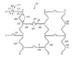
- FIG. 1Ashows a first an introducer in perspective view with a first prosthesis partially deployed.
- FIG. 1Bis an enlarged partial view of a portion of the first prosthesis in FIG. 1A , depicting the first prosthesis having a fenestration.
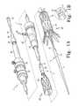
- FIG. 2shows the portion of the introducer around the proximal end of the prosthesis in detail.
- FIG. 3shows the portion of the introducer around the distal end of the prosthesis in detail.
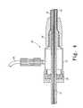
- FIG. 4shows the portion of the introducer around the haemostatic seal in detail.
- FIG. 5shows the portion of the introducer around the trigger wire release mechanisms in detail.
- FIG. 6shows the portion of the introducer around the pin vise clamp and the medical reagent introduction tube in detail.
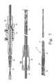
- FIG. 7shows the introducer of FIG. 1 fully loaded and ready for introduction into a patient.
- FIG. 8shows the introducer of FIG. 7 in the next stage of deployment of the prosthesis.
- FIG. 9shows the introducer of FIG. 7 with the release of the proximal end stage of deployment.
- FIG. 10shows the introducer of FIG. 7 with the release of the distal end stage of deployment.
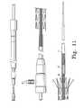
- FIG. 11shows the advancement of the distal attachment mechanism to the proximal attachment mechanism.
- FIG. 12shows the withdrawal of the introducer.
- FIG. 13is a flexible stent that is a radially expandable and laterally flexible.
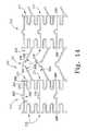
- FIG. 14is an enlarged side view of closed cells of the flexible stent of FIG. 13 in an unexpanded state.
- FIG. 15is an enlarged side view of closed cells of the flexible stent of FIG. 13 in an expanded state.
- FIG. 15 ais an enlarged side view of closed cells of the flexible stent of FIG. 13 in an expanded state, with arms of an interconnection member at about 180 degrees.
- FIG. 15 bis an enlarged partial side view of closed cells of the flexible stent of FIG. 15 a in an expanded state, with folded arms at about 180 degrees.
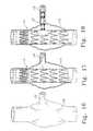
- FIG. 16is a front view of a main lumen and a branch lumen fluid communication with the main lumen.
- FIG. 17is a front view of the main lumen and the branch lumen of FIG. 17 after the prosthesis of FIG. 1 has been implanted.
- FIG. 18is a front view of the main lumen and the branch lumen of FIG. 17 after both the prosthesis of FIG. 1 and the prosthesis of FIG. 13 have been implanted.
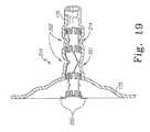
- FIG. 19is a detailed front view of the prosthesis of FIG. 13 after implantation.
- FIG. 1shows an endoluminal prosthesis 20 , and an endovascular deployment system, also known as an introducer, for deploying the prosthesis 20 in a lumen of a patient during a medical procedure.
- prosthesismeans any replacement for a body part or function of that body part. It can also mean a device that enhances or adds functionality to a physiological system.
- endoluminal and intraluminaldescribe objects that are found or can be placed inside a lumen in the human or animal body.
- a lumencan be an existing lumens or a lumen created by surgical intervention. This includes lumens such as blood vessels, parts of the gastrointestinal tract, ducts such as bile ducts, parts of the respiratory system, etc.
- Endoluminal prosthesisthus describes a prosthesis that can be placed inside one of these lumens.
- the introducerincludes an external manipulation section 1 , a distal positioning mechanism (attachment region) 2 and a proximal positioning mechanism (attachment region) region 3 .
- the external manipulation section 1which is acted upon by a user to manipulate the introducer, remains outside of the patient throughout the procedure.
- the prosthesis 20comprises a tubular graft material 50 , with self expanding stents 19 attached thereto.
- graftmeans the generally cannular or tubular member which acts as an artificial vessel.
- a graft by itself or with the addition of other elementscan be an endoluminal prosthesis.
- stentmeans any device or structure that adds rigidity, expansion force or support to a prosthesis.
- the tubular graft material 50is preferably non-porous so that it does not leak or sweat under physiologic forces.
- the graft materialis preferably made of woven DACRON® polyester (VASCUTEK® Ltd., Renfrewshire, Scotland, UK).
- the tubular graftcan be made of any other at least substantially biocompatible material including such fabrics as other polyester fabrics, polytetrafluoroethylene (PTFE), expanded PTFE, and other synthetic materials known to those of skill in the art.
- Naturally occurring biomaterials, such as collagenare also highly desirable, particularly a derived collagen material known as extracellular matrix (ECM), such as small intestinal submucosa (SIS).
- ECMextracellular matrix
- SISsmall intestinal submucosa
- ECMsare pericardium, stomach submucosa, liver basement membrane, urinary bladder submucosa, tissue mucosa, and dura mater.
- SISis particularly useful, and can be made in the fashion described in U.S. Pat. No. 4,902,508 to Badylak et al.; U.S. Pat. No. 5,733,337 to Carr; 17 Nature Biotechnology 1083 (November 1999); and WIPO Publication WO 98/22158 of May 28, 1998, to Cook et al., which is the published application of PCT/U.S.97/14855. All of these patents and publications are incorporated herein by reference.
- the graft materialcan be made thicker by making multi-laminate constructs, for example SIS constructs as described in U.S. Pat. Nos. 5,968,096; 5,955,110; 5,885,619; and 5,711,969. All of these patents are incorporated herein by reference.
- SIS constructsas described in U.S. Pat. Nos. 5,968,096; 5,955,110; 5,885,619; and 5,711,969. All of these patents are incorporated herein by reference.
- autologous tissuecan be harvested as well, for use in forming the graft material.
- ELPselastin or elastin-like polypeptides
- the self expanding stents 19cause the prosthesis 20 to expand following its disengagement from the introducer.
- the prosthesis 20also includes a self expanding zigzag stent 21 that extends from its proximal end. When it is disengaged, the self expanding zigzag stent 21 anchors the proximal end of the prosthesis 20 to the lumen.
- Radiographic markers 18may be attached to the tubular graft material 50 adjacent to the fenestration 17 in order to aid alignment of the fenestration 17 with a branch vessel.
- the radiographic markers 18may be small rings of metal, such as stainless steel, sewn to the tubular graft material 50 with suture.
- FIG. 2shows the proximal attachment region 3 in greater detail.
- the proximal attachment region 3includes a cylindrical sleeve 10 .
- the cylindrical sleeve 10has a long tapered flexible extension 11 extending from its proximal end.
- the flexible extension 11has an internal longitudinal aperture 12 .
- the longitudinal aperture 12facilitates advancement of the tapered flexible extension 11 along an insertion wire 13 .
- the aperture 12also provides a channel for the introduction of medical reagents, which will flow through openings 14 . For example, it may be desirable to supply a contrast agent to allow angiography to be performed during placement and deployment phases of the medical procedure.
- a thin walled metal tube 15is fastened to the extension 11 .
- the thin walled metal tube 15is flexible so that the introducer can be advanced along a relatively tortuous vessel, such as a femoral artery, and also to allow manipulation longitudinally and rotationally of the proximal attachment region 3 .
- the thin walled metal tube 15extends through the introducer to the manipulation section 1 , terminating at a connection means 16 , as shown in FIG. 6 .
- FIG. 6also shows that the connection means 16 is adapted to accept a syringe to facilitate the introduction of reagents into the metal tube 15 .
- the metal tube 15is in fluid communication with the aperture 12 of the flexible extension 11 . Therefore, reagents introduced into connection means 16 flow through the aperture 12 and emanate from the apertures 14 .
- a plastic tube 41is coaxial with and radially outside the thin walled metal tube 15 .
- the plastic tube 41is “thick walled”, that is to say the thickness of its wall is several times that of the thin walled metal tube 15 .
- a sheath 30is coaxial with and radially outside the thick walled tube 41 .
- the thick walled plastic tube 41 and the sheath 30extend distally to the manipulation region 1 , as shown in FIG. 5 .
- FIGS. 2 and 3illustrate retention and distal and proximal release mechanisms of the introducer, respectively.
- the prosthesis 20is retained in a compressed condition by the sheath 30 .
- the sheath 30extends distally to a gripping and haemostatic sealing means 35 of the external manipulation section 1 , shown in FIG. 4 .
- the sheath 30is advanced over the cylindrical sleeve 10 of the proximal attachment region 3 while the prosthesis 20 is held in a compressed state by an external force.
- a distal attachment (retention) section 40is formed in the thick walled plastic tube 41 to retain the distal end of the prosthesis 20 .
- the distal attachment section 40may be a separate piece coupled to the thick walled plastic tube 41 .
- the self-expanding stent 21is released by retracting the sheath 30 , removing the trigger wire 22 , and then sliding the proximal attachment region 3 , including the retention device 10 , proximally away from the stent 21 . Once the retention device 10 has cleared the self-expanding stent 21 , the stent 21 will expand.
- the trigger wire 22 and the proximal wire release mechanism 24form a control member to selectively release the retention device 10 from the prosthesis 20 by holding the self-expanding stent 21 in the retention device 10 until the prosthesis 20 is positioned at a desired site in the lumen.
- the distal end 42 of the prosthesis 20is retained by the distal attachment section 40 of the thick walled tube 41 .
- the distal end 42 of the prosthesis 20has a loop 43 through which a distal trigger wire 44 extends.
- the distal trigger wire 44extends through an aperture 45 in the distal attachment section 40 into the annular region between the thin walled tube 15 and the thick walled tube 41 .
- the distal trigger wire 44extends through the annular space between the thick walled plastic tube 41 and the thin walled tube 15 to the manipulation region 1 .
- the distal trigger wire 44exits the annular space at a distal wire release mechanism 25 .
- the distal trigger wire 44 and the distal wire release mechanism 25forms a control member to selectively disengage the distal retention section 40 from the prosthesis 20 when it is positioned at a desired site in the lumen.
- FIG. 4shows the haemostatic sealing means 35 of the external manipulation section 1 in greater detail.
- the haemostatic sealing means 35includes a haemostatic seal 27 and a side tube 29 .
- the haemostatic seal 27includes a clamping collar 26 that clamps the sheath 30 to the haemostatic seal 27 .
- the haemostatic seal 27also includes a silicone seal ring 28 .
- the silicone seal ring 28forms a haemostatic seal around the thick walled tube 41 .
- the side tube 29facilitates the introduction of medical reagents between the thick walled tube 41 and the sheath 30 .
- FIG. 5shows a proximal portion of the external manipulation section 1 .
- the release wire actuation sectionhas a body 36 that is mounted onto the thick walled plastic tube 41 .
- the thin walled tube 15passes through the body 36 .
- the distal wire release mechanism 25is mounted for slidable movement on the body 36 .
- the proximal wire release mechanism 22is mounted for slidable movement on the body 36 .
- a pair of clamping screws 37prevents inadvertent early release of the prosthesis 20 .
- the positioning of the proximal and distal wire release mechanisms 24 and 25is such that the proximal wire release mechanism 24 must be moved before the distal wire release mechanism 25 can be moved. Therefore, the distal end 42 of the prosthesis 20 cannot be released until the self-expanding zigzag stent 21 has been released and anchored to the lumen.
- a haemostatic seal 38is provided so the release wires 22 and 44 can extend out through the body 36 to the release mechanisms 24 and 25 without unnecessary blood loss during the medical procedure.
- FIG. 6shows a distal portion of the external manipulation section 1 .
- a pin vise 39is mounted onto the distal end of the body 36 .
- the pin vise 39has a screw cap 46 .
- the vise jaws 47clamp against (engage) the thin walled metal tube 15 .
- the thin walled tube 15can only move with the body 36 , and hence the thin walled tube 15 can only move with the thick walled tube 41 .
- the screw cap 46tightened, the entire assembly, except for the external sleeve 30 , can be moved as one.
- the prosthesis 20can be deployed in any method known in the art, preferably the method described in WO98/53761 in which the device is inserted by an introducer via a surgical cut-down into a femoral artery, and then advanced into the desired position over a stiff wire guide using endoluminal interventional techniques.
- FIGS. 7 through 12show various stages of the deployment of the prosthesis 20 during an illustrative medical procedure.
- a guide wire 13is introduced into the femoral artery and advanced until its tip is beyond the region into which the prosthesis 20 is to be deployed.
- the introducer assemblyis shown fully assembled ready for introduction into a patient.
- the prosthesis 20is retained at each of its ends by the proximal and distal retaining assemblies respectively, and compressed by the external sleeve 30 .
- the introducer assemblycan be inserted through a femoral artery over the guide wire 13 in the form as shown in FIG. 7 , and positioned by radiographic techniques (not discussed here).
- the fenestration 17 of the prosthesis 20may be aligned with a branch vessel, such as a renal artery, during this positioning.
- the introducer assemblyis in a desired position for deployment of the prosthesis 20 .
- the external sheath 30is withdrawn to just proximal of the distal attachment section 40 . This action releases the middle portion of the prosthesis 20 so that it can expand radially.
- the proximal self-expanding stent 21is still retained within the retention device 10 .
- the distal end 42 of the prosthesis 20is still retained within the external sheath 30 .
- the prosthesis 20may be lengthened or shortened or rotated or compressed for accurate placement in the desired location within the lumen.
- X-ray opaque markersmay be placed along the prosthesis 20 to assist with placement of the prosthesis.
- the proximal trigger wire 22has been removed, allowing the retention device 10 to be separated from the self-expanding zigzag stent 21 , as explained above.
- the proximal trigger wire release mechanism 24 and the proximal trigger wire 22can be removed completely.
- the screw cap 46 of the pin vise 39has been loosened so that the thin walled tubing 15 can been pushed in a proximal direction to move the proximal attachment means 10 in a proximal direction.
- the proximal attachment means 10no longer surrounds the self-expanding stent 21 at the proximal end of the prosthesis 20
- the self-expanding stent 21expands.
- the hooks or barbs 26 on the self-expanding stent 21grip into the walls of the lumen to hold the proximal end of the prosthesis 20 in place.
- the distal end 42 of the prosthesis 20is still retained by the distal attachment means 40 , with the loop 43 retained therein.
- the external sheath 30is then withdrawn to distal of the distal attachment section 40 to allow the distal end 42 of the prosthesis 20 to expand.
- the distal end 42 of the prosthesis 20may still be moved. Consequently, the prosthesis 20 can still be rotated or lengthened or shortened or otherwise moved for accurate positioning. Where the prosthesis 20 to be deployed is a bifurcated graft, the movement at this stage may ensure that the shorter leg is directed in the direction of the contra-iliac artery.
- the distal end 42 of the prosthesis 20has been released by removal of the distal trigger wire 44 .
- the distal trigger wire release mechanism 25 and the distal trigger wire 44can be removed completely. This removal may be accomplished by passing the distal wire release mechanism 25 over the pin vise 39 and the connection means 16 .
- the loop 43 of the terminal distal self-expanding zigzag stent 19is hence released, and the prosthesis 20 is now free to expand to the walls of the vessel. At this point, the introducer is ready to be removed.
- FIG. 11the first stage of removal is shown. First, the distal attachment section 40 is advanced until it is received in the rear of the proximal attachment device 10 . Next, the proximal attachment device 10 , the tapered flexible extension 11 , and the distal attachment device 40 are removed together, as shown in FIG. 11 .
- the sheath 30has been advanced to uncover the joint between the proximal attachment device 10 and the distal attachment section 40 .
- the sheath 30may be removed with the proximal attachment device 10 , the tapered flexible extension 11 and the distal attachment device 40 . Alternatively, these items could be removed separately, followed by removal of the external sleeve 30 .
- FIG. 13depicts a flexible stent 210 , which is a radially expandable and laterally flexible.
- the flexible stent 210is shown in FIG. 13 in an unexpanded state.
- the flexible stent 210is configured to have an outer diameter approximately equal to the diameter of fenestration 17 of the prosthesis 20 , so that the flexible stent 210 may be tightly coupled to the prosthesis 20 , as shown in FIG. 20 .
- the flexible stent 210which is comprised of an elongated member 211 with a passage 212 extending longitudinally therethrough, is formed from a tube of malleable, biocompatible material such as stainless steel. By annealing the stainless steel, the metal is soft and plastically deformable to allow the stent 210 to be readily radially expanded using a balloon catheter.
- the endoluminal flexible stent 210may be similar in construction to stents disclosed in U.S. Pat. No. 6,464,720 entitled “Radially Expandable Stent”, which is herein incorporated by reference.
- the major difference between the flexible stent 210 and stents disclosed in U.S. Pat. No. 6,464,720 and elsewhereis that the flexible stent 210 is designed to encourage tissue prolapses between stent elements, whereas usually stents are designed to prevent tissue prolapses. The reason that the flexible stent 210 is designed thusly is so that tissue prolapses may help anchor the flexible stent 210 to the lumen.
- the flexible stent 210includes a repeating series of first and second alternating segment types.
- the first segment typeis a longitudinal segment 214 having a plurality of laterally interconnected closed cells 213 , which each cell 213 defining a first open space 223 .
- the second segment typeis a flexible interconnection segment 221 that interconnects adjacent longitudinal segments via at least one interconnection strut, member, or tab 236 .
- the longitudinal segments 214when expanded, provide the flexible stent 210 with the radial strength required to maintain patency of a lumen or vessel such as a vein, an artery, or a duct.
- the interconnection segments 221provide the flexible stent 210 with lateral flexibility necessary for placement through or into tortuous vessels or sites that are subject to many bending cycles over a large range of angles.
- the interconnection member 236is circumferentially spaced from adjacent interconnection members in order to define a second open space 224 between the interconnection members 236 and the longitudinal segments 214 .
- the interconnection member 236includes a first arm 225 and a second arm 226 .
- the first arm 225can be coupled between the longitudinal segment 214 and tab 237 and the second arm 226 can be coupled between tab 237 and another longitudinal segment 214 .
- the first and second arms 225 , 226are angled relative to one another at an angle 227 , which increases to a greater angle, up to 180 degrees, when in the expanded state, as shown in FIG. 15 .
- materialmust be removed in some manner, such as by a commercially available computer-controlled laser, leaving a framework of integrated support members that has a small surface area relative to the initial surface area of the tube or sheet.
- Other methods of manufactureinclude chemical etching using photoresistive masking techniques, machining, electrode discharge machining (EDM), or cutting with a water jet.
- the flexible stent 210also includes tabs 250 at an end thereof.
- the tabs 250may be bent radially outward from flexible stent 210 to secure the flexible stent 210 to the prosthesis 20 , as shown in FIGS. 20 and 21 .
- the flexible stent 210preferably includes at least one radio opaque marker 248 , which is preferably positioned near the tabs 250 .
- FIG. 14depicts closed cells 213 of the flexible stent 210 of FIG. 13 in an unexpanded state.
- Each closed cell 213includes a pair of longitudinal struts 215 and 216 that are circumferentially spaced from one another, which maintain longitudinal orientation during and after expansion of the flexible stent 210 .
- the longitudinal struts 215 and 216are typically shared with the two laterally adjacent cells, which are interconnected with additional closed cells 213 to form a longitudinal segment 214 .
- open cells or a combination of open and closed cellscan be used.
- the first and second longitudinal struts 215 and 216are interconnected at both ends 217 and 218 at longitudinal edges 228 that include a plurality of arms 251 , 252 interconnected by a plurality of bends 254 in a serpentine pattern.
- FIG. 15depicts an enlarged, side view of closed cells 213 of the flexible stent 210 of FIG. 13 in an expanded state.
- the cells 213 of the longitudinal segments 214are defined between the longitudinal struts 215 , 216 and the longitudinal edges 228 .
- the arms 215 , 216can be parallel to one another.
- the angle 253 between folded arms 251 and 252approaches 180 degrees and the angle 227 between the arms 225 , 226 of the interconnection member 221 approaches 180 degrees such that the second open space 224 has a substantially rectangular shape.
- FIG. 15 aillustrates the angle 227 between arms 225 and 226 at about 180 degrees.
- 15 bis an enlarged partial view of FIG. 15 a , with the angle 253 between arms 251 and 252 at about 180 degrees. Although radial strength is increased as the angle between the arms 251 and 252 increases, additional stresses placed at the points of their attachment to the longitudinal struts 215 , 216 or 236 make the preferable final angle closer to 90 degrees.
- the closed cells 213allow the nominally-sized flexible stent 210 to be deployed at different diameters within a given range.
- the expanded diameters preferred for use in peripheral and non-coronary applicationssuch the aorta, iliac, femoral, popliteal, renal, subclavian, and carotid arteries or vein graft and other venous lesions, generally range from 4.0 to 14.0 mm.
- the preferred length of the flexible stent 210would be 7 to 60 mm length, although even longer lengths could be used.
- FIG. 16is a front view of a main lumen 175 and a branch lumen 176 , wherein the lumens 175 and 176 are in fluid communication.
- the main lumen 175has an aneurism, or weakness, and exists at the attachment point of the branch lumen 176 .
- FIG. 17shows the lumens 175 and 176 after the prosthesis 20 has been successfully implanted.
- the fenestration 17is aligned with the opening of the branch lumen 176 .
- the prosthesis 20reinforces the main lumen 175 .
- FIG. 18shows the lumens 175 and 176 after the flexible stent 210 has been successfully implanted.
- the flexible stent 210performs two main functions.
- the flexible stent 210keeps the fenestration 17 aligned so that the lumens 175 and 176 remain in fluid communication.
- the flexible stent 210reinforces the branch lumen 176 , which may also be weakened because of the aneurism.
- FIG. 19shows the implanted flexible stent 210 in more detail. Because the second open spaces 224 of the longitudinal segments 221 contain a significant amount of open space, typically more than the first open spaces 223 , tissue prolapses 302 develop in the lumen 176 to fill the void. These tissue prolapses 302 exert force on the longitudinal segments 214 , so that the entire flexible stent 210 is anchored to the lumen 176 thereby.
- the flexible stent 210can be implanted at the desired location by crimping the flexible stent 210 onto a conventional angioplasty balloon and locating the balloon at the desired location.
- the flexible stent 210can then be expanded by the balloon at the desired location in a manner similar to a conventional angioplasty stent.
- the tabs 250are shown in FIGS. 18 and 19 bent radially outward from the body 211 of the stent 210 . Such bending of the tabs 250 may be accomplished by locating the balloon in the lumen 176 , and then “over inflating” the balloon. Alternatively, another balloon device may be used that is particularly suited for bending the tabs 250 .
Landscapes
- Health & Medical Sciences (AREA)
- Engineering & Computer Science (AREA)
- Biomedical Technology (AREA)
- Life Sciences & Earth Sciences (AREA)
- General Health & Medical Sciences (AREA)
- Transplantation (AREA)
- Heart & Thoracic Surgery (AREA)
- Vascular Medicine (AREA)
- Cardiology (AREA)
- Animal Behavior & Ethology (AREA)
- Oral & Maxillofacial Surgery (AREA)
- Public Health (AREA)
- Veterinary Medicine (AREA)
- Physics & Mathematics (AREA)
- Optics & Photonics (AREA)
- Gastroenterology & Hepatology (AREA)
- Pulmonology (AREA)
- Prostheses (AREA)
Abstract
Description
Claims (16)
Priority Applications (1)
| Application Number | Priority Date | Filing Date | Title |
|---|---|---|---|
| US11/491,632US7833259B2 (en) | 2005-07-25 | 2006-07-24 | Fenestrated endoluminal stent system |
Applications Claiming Priority (2)
| Application Number | Priority Date | Filing Date | Title |
|---|---|---|---|
| US70220005P | 2005-07-25 | 2005-07-25 | |
| US11/491,632US7833259B2 (en) | 2005-07-25 | 2006-07-24 | Fenestrated endoluminal stent system |
Publications (2)
| Publication Number | Publication Date |
|---|---|
| US20070021822A1 US20070021822A1 (en) | 2007-01-25 |
| US7833259B2true US7833259B2 (en) | 2010-11-16 |
Family
ID=37450923
Family Applications (1)
| Application Number | Title | Priority Date | Filing Date |
|---|---|---|---|
| US11/491,632Active2027-12-02US7833259B2 (en) | 2005-07-25 | 2006-07-24 | Fenestrated endoluminal stent system |
Country Status (2)
| Country | Link |
|---|---|
| US (1) | US7833259B2 (en) |
| WO (1) | WO2007014088A2 (en) |
Cited By (35)
| Publication number | Priority date | Publication date | Assignee | Title |
|---|---|---|---|---|
| US8034100B2 (en) | 1999-03-11 | 2011-10-11 | Endologix, Inc. | Graft deployment system |
| US8118856B2 (en) | 2009-07-27 | 2012-02-21 | Endologix, Inc. | Stent graft |
| US8167925B2 (en) | 1999-03-11 | 2012-05-01 | Endologix, Inc. | Single puncture bifurcation graft deployment system |
| US8491646B2 (en) | 2009-07-15 | 2013-07-23 | Endologix, Inc. | Stent graft |
| US8523931B2 (en) | 2007-01-12 | 2013-09-03 | Endologix, Inc. | Dual concentric guidewire and methods of bifurcated graft deployment |
| US8709068B2 (en) | 2007-03-05 | 2014-04-29 | Endospan Ltd. | Multi-component bifurcated stent-graft systems |
| US8808350B2 (en) | 2011-03-01 | 2014-08-19 | Endologix, Inc. | Catheter system and methods of using same |
| US8945203B2 (en) | 2009-11-30 | 2015-02-03 | Endospan Ltd. | Multi-component stent-graft system for implantation in a blood vessel with multiple branches |
| US8945202B2 (en) | 2009-04-28 | 2015-02-03 | Endologix, Inc. | Fenestrated prosthesis |
| US9101507B2 (en) | 2011-05-18 | 2015-08-11 | Ralph F. Caselnova | Apparatus and method for proximal-to-distal endoluminal stent deployment |
| US9186267B2 (en) | 2012-10-31 | 2015-11-17 | Covidien Lp | Wing bifurcation reconstruction device |
| US9351859B2 (en) | 2010-12-06 | 2016-05-31 | Covidien Lp | Vascular remodeling device |
| US9393100B2 (en) | 2010-11-17 | 2016-07-19 | Endologix, Inc. | Devices and methods to treat vascular dissections |
| US9427339B2 (en) | 2011-10-30 | 2016-08-30 | Endospan Ltd. | Triple-collar stent-graft |
| US9579103B2 (en) | 2009-05-01 | 2017-02-28 | Endologix, Inc. | Percutaneous method and device to treat dissections |
| US9597204B2 (en) | 2011-12-04 | 2017-03-21 | Endospan Ltd. | Branched stent-graft system |
| US9668892B2 (en) | 2013-03-11 | 2017-06-06 | Endospan Ltd. | Multi-component stent-graft system for aortic dissections |
| US9700701B2 (en) | 2008-07-01 | 2017-07-11 | Endologix, Inc. | Catheter system and methods of using same |
| US9770350B2 (en) | 2012-05-15 | 2017-09-26 | Endospan Ltd. | Stent-graft with fixation elements that are radially confined for delivery |
| US9839510B2 (en) | 2011-08-28 | 2017-12-12 | Endospan Ltd. | Stent-grafts with post-deployment variable radial displacement |
| EP3272314A1 (en) | 2016-07-21 | 2018-01-24 | Cook Medical Technologies LLC | Tapered body aaa graft |
| US9918825B2 (en) | 2009-06-23 | 2018-03-20 | Endospan Ltd. | Vascular prosthesis for treating aneurysms |
| US9993360B2 (en) | 2013-01-08 | 2018-06-12 | Endospan Ltd. | Minimization of stent-graft migration during implantation |
| US10245166B2 (en) | 2008-02-22 | 2019-04-02 | Endologix, Inc. | Apparatus and method of placement of a graft or graft system |
| WO2019089385A1 (en)* | 2017-11-02 | 2019-05-09 | Silk Road Medical, Inc. | Fenestrated sheath for embolic protection during transcarotid carotid artery revascularization |
| US10470871B2 (en) | 2001-12-20 | 2019-11-12 | Trivascular, Inc. | Advanced endovascular graft |
| US10485684B2 (en) | 2014-12-18 | 2019-11-26 | Endospan Ltd. | Endovascular stent-graft with fatigue-resistant lateral tube |
| US10603197B2 (en) | 2013-11-19 | 2020-03-31 | Endospan Ltd. | Stent system with radial-expansion locking |
| US10722342B2 (en) | 2011-04-28 | 2020-07-28 | The Cleveland Clinic Foundation | Endoluminal prosthesis having multiple branches or fenestrations and methods of deployment |
| US10772717B2 (en) | 2009-05-01 | 2020-09-15 | Endologix, Inc. | Percutaneous method and device to treat dissections |
| US10888414B2 (en) | 2019-03-20 | 2021-01-12 | inQB8 Medical Technologies, LLC | Aortic dissection implant |
| US11129737B2 (en) | 2015-06-30 | 2021-09-28 | Endologix Llc | Locking assembly for coupling guidewire to delivery system |
| US11406518B2 (en) | 2010-11-02 | 2022-08-09 | Endologix Llc | Apparatus and method of placement of a graft or graft system |
| US11433226B2 (en) | 2015-04-10 | 2022-09-06 | Silk Road Medical, Inc. | Methods and systems for establishing retrograde carotid arterial blood flow |
| US11446168B2 (en) | 2017-04-25 | 2022-09-20 | Cook Medical Technologies Llc | Prosthesis with side branch and method of making the same |
Families Citing this family (54)
| Publication number | Priority date | Publication date | Assignee | Title |
|---|---|---|---|---|
| WO2002039888A2 (en)* | 2000-11-15 | 2002-05-23 | Endologix, Inc. | Implantable vascular graft |
| US20070027535A1 (en)* | 2005-07-28 | 2007-02-01 | Cook Incorporated | Implantable thromboresistant valve |
| US8038708B2 (en)* | 2001-02-05 | 2011-10-18 | Cook Medical Technologies Llc | Implantable device with remodelable material and covering material |
| US7318437B2 (en) | 2003-02-21 | 2008-01-15 | Resmed Limited | Nasal assembly |
| US11259945B2 (en) | 2003-09-03 | 2022-03-01 | Bolton Medical, Inc. | Dual capture device for stent graft delivery system and method for capturing a stent graft |
| US20070198078A1 (en) | 2003-09-03 | 2007-08-23 | Bolton Medical, Inc. | Delivery system and method for self-centering a Proximal end of a stent graft |
| US8500792B2 (en) | 2003-09-03 | 2013-08-06 | Bolton Medical, Inc. | Dual capture device for stent graft delivery system and method for capturing a stent graft |
| US7763063B2 (en) | 2003-09-03 | 2010-07-27 | Bolton Medical, Inc. | Self-aligning stent graft delivery system, kit, and method |
| US9198786B2 (en) | 2003-09-03 | 2015-12-01 | Bolton Medical, Inc. | Lumen repair device with capture structure |
| US8292943B2 (en) | 2003-09-03 | 2012-10-23 | Bolton Medical, Inc. | Stent graft with longitudinal support member |
| US20080264102A1 (en) | 2004-02-23 | 2008-10-30 | Bolton Medical, Inc. | Sheath Capture Device for Stent Graft Delivery System and Method for Operating Same |
| US11596537B2 (en) | 2003-09-03 | 2023-03-07 | Bolton Medical, Inc. | Delivery system and method for self-centering a proximal end of a stent graft |
| EP2510968B1 (en) | 2003-12-31 | 2017-02-08 | ResMed Limited | Compact oronasal patient interface |
| US20070246043A1 (en) | 2004-04-15 | 2007-10-25 | Resmed Limited | Positive-Air-Pressure Machine Conduit |
| NZ563608A (en) | 2005-06-06 | 2011-03-31 | Resmed Ltd | A mask with upper and lower stabilization parts contoured to the shape of a human face as part of the straps |
| NZ701722A (en) | 2006-07-28 | 2016-07-29 | Resmed Ltd | Delivery of respiratory therapy |
| EP2428241B1 (en) | 2006-07-28 | 2016-07-06 | ResMed Limited | Delivery of respiratory therapy |
| US20080071343A1 (en)* | 2006-09-15 | 2008-03-20 | Kevin John Mayberry | Multi-segmented graft deployment system |
| WO2008053469A2 (en)* | 2006-10-29 | 2008-05-08 | Alon Shalev | An extra-vascular wrapping for treating aneurysmatic aorta and methods thereof |
| EP2481434B1 (en) | 2006-12-15 | 2016-04-13 | ResMed Ltd. | Delivery of respiratory therapy |
| EP2053033A1 (en) | 2007-10-26 | 2009-04-29 | Bayer Schering Pharma AG | Compounds for use in imaging, diagnosing and/or treatment of diseases of the central nervous system or of tumors |
| CN101965162B (en) | 2007-12-15 | 2014-12-10 | 恩多斯潘有限公司 | Extra-vascular wrapping for treating aneurysmatic aorta in conjunction with endovascular stent-graft and methods thereof |
| US8236040B2 (en) | 2008-04-11 | 2012-08-07 | Endologix, Inc. | Bifurcated graft deployment systems and methods |
| US20090270971A1 (en)* | 2008-04-24 | 2009-10-29 | Medtronic Vascular, Inc. | Prosthesis Fixation Apparatus and Methods |
| FR2930889B1 (en) | 2008-05-12 | 2011-12-16 | Hexacath | IMPLANTABLE MEDICAL DEVICE WITH A PROXIMAL END, A POSITIONING MEANS AT A PRECISE LOCATION OF THE CONNECTION OF A BLOOD VESSEL SUCH AS A CORONARY |
| NZ618492A (en) | 2008-06-05 | 2015-09-25 | Resmed Ltd | Treatment of respiratory conditions |
| CN102076281B (en) | 2008-06-30 | 2014-11-05 | 波顿医疗公司 | Systems and methods for abdominal aortic aneurysm |
| EP3284447B1 (en)* | 2009-03-13 | 2020-05-20 | Bolton Medical Inc. | System for deploying an endoluminal prosthesis at a surgical site |
| CN108310580B (en) | 2009-06-02 | 2023-06-13 | 瑞思迈私人有限公司 | Non-highlighting nasal mask |
| WO2011004374A1 (en) | 2009-07-09 | 2011-01-13 | Endospan Ltd. | Apparatus for closure of a lumen and methods of using the same |
| WO2011059707A1 (en)* | 2009-10-29 | 2011-05-19 | William A. Cook Australia Pty. Ltd. | Stent delivery system with nitinol trigger wire |
| EP2509535B1 (en) | 2009-12-08 | 2016-12-07 | Endospan Ltd | Endovascular stent-graft system with fenestrated and crossing stent-grafts |
| WO2011080738A1 (en) | 2009-12-31 | 2011-07-07 | Endospan Ltd. | Endovascular flow direction indicator |
| US9468517B2 (en) | 2010-02-08 | 2016-10-18 | Endospan Ltd. | Thermal energy application for prevention and management of endoleaks in stent-grafts |
| US8523932B2 (en)* | 2010-05-24 | 2013-09-03 | Cook Medical Technologies Llc | Variable diameter trigger wire |
| EP2621573B1 (en) | 2010-09-30 | 2016-12-21 | ResMed Limited | Mask system |
| WO2012040791A1 (en) | 2010-09-30 | 2012-04-05 | Resmed Limited | Patient interface systems |
| CA2826022A1 (en) | 2011-02-03 | 2012-08-09 | Endospan Ltd. | Implantable medical devices constructed of shape memory material |
| WO2012111006A1 (en) | 2011-02-17 | 2012-08-23 | Endospan Ltd. | Vascular bands and delivery systems therefor |
| WO2012117395A1 (en) | 2011-03-02 | 2012-09-07 | Endospan Ltd. | Reduced-strain extra- vascular ring for treating aortic aneurysm |
| US8574287B2 (en) | 2011-06-14 | 2013-11-05 | Endospan Ltd. | Stents incorporating a plurality of strain-distribution locations |
| US8951298B2 (en) | 2011-06-21 | 2015-02-10 | Endospan Ltd. | Endovascular system with circumferentially-overlapping stent-grafts |
| US9254209B2 (en) | 2011-07-07 | 2016-02-09 | Endospan Ltd. | Stent fixation with reduced plastic deformation |
| EP2846743B1 (en) | 2012-04-12 | 2016-12-14 | Bolton Medical Inc. | Vascular prosthetic delivery device |
| US9439751B2 (en) | 2013-03-15 | 2016-09-13 | Bolton Medical, Inc. | Hemostasis valve and delivery systems |
| EP3903732B1 (en) | 2016-06-13 | 2025-07-30 | Bolton Medical, Inc. | Devices for reinforcing fenestrations in prosthetic implants |
| WO2018156848A1 (en) | 2017-02-24 | 2018-08-30 | Bolton Medical, Inc. | Vascular prosthesis with crimped adapter and methods of use |
| WO2018156847A1 (en) | 2017-02-24 | 2018-08-30 | Bolton Medical, Inc. | Delivery system and method to radially constrict a stent graft |
| WO2018156850A1 (en) | 2017-02-24 | 2018-08-30 | Bolton Medical, Inc. | Stent graft with fenestration lock |
| WO2018156851A1 (en) | 2017-02-24 | 2018-08-30 | Bolton Medical, Inc. | Vascular prosthesis with moveable fenestration |
| ES2954897T3 (en) | 2017-02-24 | 2023-11-27 | Bolton Medical Inc | Constrained Wrap Stent Graft Delivery System |
| JP7271510B2 (en) | 2017-09-25 | 2023-05-11 | ボルトン メディカル インコーポレイテッド | Systems, devices and methods for coupling prosthetic implants to fenestrated bodies |
| US11109939B2 (en)* | 2019-06-14 | 2021-09-07 | DePuy Synthes Products, Inc. | Intravascular devices with radiopaque body markers |
| EP4585192A3 (en) | 2020-06-24 | 2025-10-15 | Bolton Medical, Inc. | Anti-backspin component for vascular prosthesis delivery device |
Citations (48)
| Publication number | Priority date | Publication date | Assignee | Title |
|---|---|---|---|---|
| US4562596A (en) | 1984-04-25 | 1986-01-07 | Elliot Kornberg | Aortic graft, device and method for performing an intraluminal abdominal aortic aneurysm repair |
| US4665918A (en) | 1986-01-06 | 1987-05-19 | Garza Gilbert A | Prosthesis system and method |
| US4902508A (en) | 1988-07-11 | 1990-02-20 | Purdue Research Foundation | Tissue graft composition |
| EP0364787A1 (en) | 1988-10-04 | 1990-04-25 | EXPANDABLE GRAFTS PARTNERSHIP a Texas General Partnership | Expandable intraluminal graft |
| US4950227A (en) | 1988-11-07 | 1990-08-21 | Boston Scientific Corporation | Stent delivery system |
| EP0421729A2 (en) | 1989-10-02 | 1991-04-10 | Medtronic, Inc. | Articulated stent |
| EP0441516A2 (en) | 1990-02-08 | 1991-08-14 | Howmedica Inc. | Inflatable stent |
| US5387235A (en) | 1991-10-25 | 1995-02-07 | Cook Incorporated | Expandable transluminal graft prosthesis for repair of aneurysm |
| US5593442A (en) | 1995-06-05 | 1997-01-14 | Localmed, Inc. | Radially expansible and articulated vessel scaffold |
| US5607444A (en) | 1993-12-02 | 1997-03-04 | Advanced Cardiovascular Systems, Inc. | Ostial stent for bifurcations |
| US5711969A (en) | 1995-04-07 | 1998-01-27 | Purdue Research Foundation | Large area submucosal tissue graft constructs |
| US5720776A (en) | 1991-10-25 | 1998-02-24 | Cook Incorporated | Barb and expandable transluminal graft prosthesis for repair of aneurysm |
| US5733337A (en) | 1995-04-07 | 1998-03-31 | Organogenesis, Inc. | Tissue repair fabric |
| WO1998020810A1 (en) | 1996-11-12 | 1998-05-22 | Medtronic, Inc. | Flexible, radially expansible luminal prostheses |
| WO1998022158A2 (en) | 1996-08-23 | 1998-05-28 | Cook Biotech, Incorporated | Graft prosthesis, materials and methods |
| WO1998053761A1 (en) | 1997-05-26 | 1998-12-03 | William A. Cook Australia Pty. Ltd. | A prosthesis and a method and means of deploying a prosthesis |
| US5855600A (en)* | 1997-08-01 | 1999-01-05 | Inflow Dynamics Inc. | Flexible implantable stent with composite design |
| WO1999029262A1 (en) | 1997-12-10 | 1999-06-17 | William A. Cook Australia Pty. Ltd. | Endoluminal aortic stents |
| WO1999036002A1 (en) | 1996-11-04 | 1999-07-22 | Advanced Stent Technologies, Inc. | Extendible stent apparatus |
| US5968096A (en) | 1996-04-05 | 1999-10-19 | Purdue Research Foundation | Method of repairing perforated submucosal tissue graft constructs |
| US6231598B1 (en)* | 1997-09-24 | 2001-05-15 | Med Institute, Inc. | Radially expandable stent |
| US6261319B1 (en)* | 1998-07-08 | 2001-07-17 | Scimed Life Systems, Inc. | Stent |
| US20010016766A1 (en) | 1996-11-04 | 2001-08-23 | Vardi Gil M. | Extendible stent apparatus |
| US6348065B1 (en) | 1995-03-01 | 2002-02-19 | Scimed Life Systems, Inc. | Longitudinally flexible expandable stent |
| US6416539B1 (en)* | 1997-06-30 | 2002-07-09 | Medex, Inc. | Controlled length intraluminal implant |
| US6527799B2 (en) | 1998-10-29 | 2003-03-04 | Conor Medsystems, Inc. | Expandable medical device with ductile hinges |
| WO2003034948A1 (en) | 2001-10-26 | 2003-05-01 | Cook Incorporated | Prostheses for curved lumens |
| US6565600B2 (en) | 1997-03-10 | 2003-05-20 | Cordis Corporation | Articulated expandable intraluminal stent |
| US6582394B1 (en) | 2000-11-14 | 2003-06-24 | Advanced Cardiovascular Systems, Inc. | Stent and catheter assembly and method for treating bifurcated vessels |
| US6585758B1 (en) | 1999-11-16 | 2003-07-01 | Scimed Life Systems, Inc. | Multi-section filamentary endoluminal stent |
| WO2003053287A1 (en) | 2001-12-19 | 2003-07-03 | Cook Incorporated | Stent graft with improved graft adhesion |
| US20030229389A1 (en)* | 2000-05-01 | 2003-12-11 | Escano Arnold M. | Lock modular graft component junctions |
| US20030233140A1 (en) | 2002-05-29 | 2003-12-18 | William A. Cook Australia Pty Ltd | Trigger wire system |
| US20040044396A1 (en) | 1997-05-27 | 2004-03-04 | Clerc Claude O. | Stent and stent-graft for treating branched vessels |
| US20040054396A1 (en) | 2002-06-26 | 2004-03-18 | Cook Incorporated | Stent-graft fastening |
| US20040106972A1 (en)* | 2000-11-20 | 2004-06-03 | Deaton David H. | Fenestrated endovascular graft |
| US20040167607A1 (en) | 2000-09-27 | 2004-08-26 | Frantzen John J. | Vascular stent-graft apparatus |
| US20040167609A1 (en)* | 2003-02-25 | 2004-08-26 | Majercak David C. | Stent with nested fingers for enhanced vessel coverage |
| US20040254627A1 (en)* | 2003-04-04 | 2004-12-16 | Thompson Paul J. | Stent with end adapted for flaring |
| US6835203B1 (en) | 1996-11-04 | 2004-12-28 | Advanced Stent Technologies, Inc. | Extendible stent apparatus |
| WO2005034807A1 (en) | 2003-10-10 | 2005-04-21 | William A. Cook Australia Pty. Ltd | Composite stent graft |
| US20050090888A1 (en) | 2003-10-28 | 2005-04-28 | Hines Richard A. | Pleated stent assembly |
| US20050149166A1 (en)* | 2003-11-08 | 2005-07-07 | Schaeffer Darin G. | Branch vessel prosthesis with anchoring device and method |
| US6926734B1 (en) | 1996-05-29 | 2005-08-09 | Avantec Vascular Corporation | Radially expansible vessel scaffold having modified radiopacity |
| US6939370B2 (en) | 2002-06-28 | 2005-09-06 | Cook Incorporated | Thoracic aortic stent graft deployment device |
| WO2005099629A1 (en) | 2004-03-31 | 2005-10-27 | Cook Incorporated | Stent deployment device |
| US7163553B2 (en)* | 2001-12-28 | 2007-01-16 | Advanced Cardiovascular Systems, Inc. | Intravascular stent and method of use |
| US7220275B2 (en) | 1996-11-04 | 2007-05-22 | Advanced Stent Technologies, Inc. | Stent with protruding branch portion for bifurcated vessels |
- 2006
- 2006-07-24WOPCT/US2006/028523patent/WO2007014088A2/enactiveApplication Filing
- 2006-07-24USUS11/491,632patent/US7833259B2/enactiveActive
Patent Citations (56)
| Publication number | Priority date | Publication date | Assignee | Title |
|---|---|---|---|---|
| US4562596A (en) | 1984-04-25 | 1986-01-07 | Elliot Kornberg | Aortic graft, device and method for performing an intraluminal abdominal aortic aneurysm repair |
| US4665918A (en) | 1986-01-06 | 1987-05-19 | Garza Gilbert A | Prosthesis system and method |
| US4902508A (en) | 1988-07-11 | 1990-02-20 | Purdue Research Foundation | Tissue graft composition |
| EP0364787A1 (en) | 1988-10-04 | 1990-04-25 | EXPANDABLE GRAFTS PARTNERSHIP a Texas General Partnership | Expandable intraluminal graft |
| US4950227A (en) | 1988-11-07 | 1990-08-21 | Boston Scientific Corporation | Stent delivery system |
| EP0421729A2 (en) | 1989-10-02 | 1991-04-10 | Medtronic, Inc. | Articulated stent |
| US5104404A (en) | 1989-10-02 | 1992-04-14 | Medtronic, Inc. | Articulated stent |
| EP0441516A2 (en) | 1990-02-08 | 1991-08-14 | Howmedica Inc. | Inflatable stent |
| US5720776A (en) | 1991-10-25 | 1998-02-24 | Cook Incorporated | Barb and expandable transluminal graft prosthesis for repair of aneurysm |
| US5387235A (en) | 1991-10-25 | 1995-02-07 | Cook Incorporated | Expandable transluminal graft prosthesis for repair of aneurysm |
| US5607444A (en) | 1993-12-02 | 1997-03-04 | Advanced Cardiovascular Systems, Inc. | Ostial stent for bifurcations |
| US6348065B1 (en) | 1995-03-01 | 2002-02-19 | Scimed Life Systems, Inc. | Longitudinally flexible expandable stent |
| US5711969A (en) | 1995-04-07 | 1998-01-27 | Purdue Research Foundation | Large area submucosal tissue graft constructs |
| US5955110A (en) | 1995-04-07 | 1999-09-21 | Purdue Research Foundation, Inc. | Multilayered submucosal graft constructs and method for making the same |
| US5733337A (en) | 1995-04-07 | 1998-03-31 | Organogenesis, Inc. | Tissue repair fabric |
| US5885619A (en) | 1995-04-07 | 1999-03-23 | Purdue Research Foundation | Large area submucosal tissue graft constructs and method for making the same |
| US5593442A (en) | 1995-06-05 | 1997-01-14 | Localmed, Inc. | Radially expansible and articulated vessel scaffold |
| US5968096A (en) | 1996-04-05 | 1999-10-19 | Purdue Research Foundation | Method of repairing perforated submucosal tissue graft constructs |
| US6926734B1 (en) | 1996-05-29 | 2005-08-09 | Avantec Vascular Corporation | Radially expansible vessel scaffold having modified radiopacity |
| WO1998022158A2 (en) | 1996-08-23 | 1998-05-28 | Cook Biotech, Incorporated | Graft prosthesis, materials and methods |
| US6206931B1 (en) | 1996-08-23 | 2001-03-27 | Cook Incorporated | Graft prosthesis materials |
| US20010016766A1 (en) | 1996-11-04 | 2001-08-23 | Vardi Gil M. | Extendible stent apparatus |
| US7220275B2 (en) | 1996-11-04 | 2007-05-22 | Advanced Stent Technologies, Inc. | Stent with protruding branch portion for bifurcated vessels |
| US6835203B1 (en) | 1996-11-04 | 2004-12-28 | Advanced Stent Technologies, Inc. | Extendible stent apparatus |
| US20010037137A1 (en) | 1996-11-04 | 2001-11-01 | Vardi Gil M. | Extendible stent apparatus |
| WO1999036002A1 (en) | 1996-11-04 | 1999-07-22 | Advanced Stent Technologies, Inc. | Extendible stent apparatus |
| WO1998020810A1 (en) | 1996-11-12 | 1998-05-22 | Medtronic, Inc. | Flexible, radially expansible luminal prostheses |
| US6270524B1 (en) | 1996-11-12 | 2001-08-07 | Medtronic, Inc. | Flexible, radially expansible luminal prostheses |
| US6565600B2 (en) | 1997-03-10 | 2003-05-20 | Cordis Corporation | Articulated expandable intraluminal stent |
| WO1998053761A1 (en) | 1997-05-26 | 1998-12-03 | William A. Cook Australia Pty. Ltd. | A prosthesis and a method and means of deploying a prosthesis |
| US6860900B2 (en) | 1997-05-27 | 2005-03-01 | Schneider (Usa) Inc. | Stent and stent-graft for treating branched vessels |
| US20040044396A1 (en) | 1997-05-27 | 2004-03-04 | Clerc Claude O. | Stent and stent-graft for treating branched vessels |
| US6416539B1 (en)* | 1997-06-30 | 2002-07-09 | Medex, Inc. | Controlled length intraluminal implant |
| US5855600A (en)* | 1997-08-01 | 1999-01-05 | Inflow Dynamics Inc. | Flexible implantable stent with composite design |
| US6231598B1 (en)* | 1997-09-24 | 2001-05-15 | Med Institute, Inc. | Radially expandable stent |
| US6464720B2 (en) | 1997-09-24 | 2002-10-15 | Cook Incorporated | Radially expandable stent |
| WO1999029262A1 (en) | 1997-12-10 | 1999-06-17 | William A. Cook Australia Pty. Ltd. | Endoluminal aortic stents |
| US6261319B1 (en)* | 1998-07-08 | 2001-07-17 | Scimed Life Systems, Inc. | Stent |
| US6527799B2 (en) | 1998-10-29 | 2003-03-04 | Conor Medsystems, Inc. | Expandable medical device with ductile hinges |
| US6585758B1 (en) | 1999-11-16 | 2003-07-01 | Scimed Life Systems, Inc. | Multi-section filamentary endoluminal stent |
| US20030229389A1 (en)* | 2000-05-01 | 2003-12-11 | Escano Arnold M. | Lock modular graft component junctions |
| US20040167607A1 (en) | 2000-09-27 | 2004-08-26 | Frantzen John J. | Vascular stent-graft apparatus |
| US6582394B1 (en) | 2000-11-14 | 2003-06-24 | Advanced Cardiovascular Systems, Inc. | Stent and catheter assembly and method for treating bifurcated vessels |
| US20040106972A1 (en)* | 2000-11-20 | 2004-06-03 | Deaton David H. | Fenestrated endovascular graft |
| WO2003034948A1 (en) | 2001-10-26 | 2003-05-01 | Cook Incorporated | Prostheses for curved lumens |
| WO2003053287A1 (en) | 2001-12-19 | 2003-07-03 | Cook Incorporated | Stent graft with improved graft adhesion |
| US7163553B2 (en)* | 2001-12-28 | 2007-01-16 | Advanced Cardiovascular Systems, Inc. | Intravascular stent and method of use |
| US20030233140A1 (en) | 2002-05-29 | 2003-12-18 | William A. Cook Australia Pty Ltd | Trigger wire system |
| US20040054396A1 (en) | 2002-06-26 | 2004-03-18 | Cook Incorporated | Stent-graft fastening |
| US6939370B2 (en) | 2002-06-28 | 2005-09-06 | Cook Incorporated | Thoracic aortic stent graft deployment device |
| US20040167609A1 (en)* | 2003-02-25 | 2004-08-26 | Majercak David C. | Stent with nested fingers for enhanced vessel coverage |
| US20040254627A1 (en)* | 2003-04-04 | 2004-12-16 | Thompson Paul J. | Stent with end adapted for flaring |
| WO2005034807A1 (en) | 2003-10-10 | 2005-04-21 | William A. Cook Australia Pty. Ltd | Composite stent graft |
| US20050090888A1 (en) | 2003-10-28 | 2005-04-28 | Hines Richard A. | Pleated stent assembly |
| US20050149166A1 (en)* | 2003-11-08 | 2005-07-07 | Schaeffer Darin G. | Branch vessel prosthesis with anchoring device and method |
| WO2005099629A1 (en) | 2004-03-31 | 2005-10-27 | Cook Incorporated | Stent deployment device |
Cited By (62)
| Publication number | Priority date | Publication date | Assignee | Title |
|---|---|---|---|---|
| US8167925B2 (en) | 1999-03-11 | 2012-05-01 | Endologix, Inc. | Single puncture bifurcation graft deployment system |
| US8034100B2 (en) | 1999-03-11 | 2011-10-11 | Endologix, Inc. | Graft deployment system |
| US11439497B2 (en) | 2001-12-20 | 2022-09-13 | Trivascular, Inc. | Advanced endovascular graft |
| US10470871B2 (en) | 2001-12-20 | 2019-11-12 | Trivascular, Inc. | Advanced endovascular graft |
| US8523931B2 (en) | 2007-01-12 | 2013-09-03 | Endologix, Inc. | Dual concentric guidewire and methods of bifurcated graft deployment |
| US8709068B2 (en) | 2007-03-05 | 2014-04-29 | Endospan Ltd. | Multi-component bifurcated stent-graft systems |
| US10245166B2 (en) | 2008-02-22 | 2019-04-02 | Endologix, Inc. | Apparatus and method of placement of a graft or graft system |
| US10512758B2 (en) | 2008-07-01 | 2019-12-24 | Endologix, Inc. | Catheter system and methods of using same |
| US9700701B2 (en) | 2008-07-01 | 2017-07-11 | Endologix, Inc. | Catheter system and methods of using same |
| US8945202B2 (en) | 2009-04-28 | 2015-02-03 | Endologix, Inc. | Fenestrated prosthesis |
| US10603196B2 (en) | 2009-04-28 | 2020-03-31 | Endologix, Inc. | Fenestrated prosthesis |
| US10772717B2 (en) | 2009-05-01 | 2020-09-15 | Endologix, Inc. | Percutaneous method and device to treat dissections |
| US9579103B2 (en) | 2009-05-01 | 2017-02-28 | Endologix, Inc. | Percutaneous method and device to treat dissections |
| US11090148B2 (en) | 2009-06-23 | 2021-08-17 | Endospan Ltd. | Vascular prosthesis for treating aneurysms |
| US9918825B2 (en) | 2009-06-23 | 2018-03-20 | Endospan Ltd. | Vascular prosthesis for treating aneurysms |
| US9757262B2 (en) | 2009-07-15 | 2017-09-12 | Endologix, Inc. | Stent graft |
| US8491646B2 (en) | 2009-07-15 | 2013-07-23 | Endologix, Inc. | Stent graft |
| US8118856B2 (en) | 2009-07-27 | 2012-02-21 | Endologix, Inc. | Stent graft |
| US9907642B2 (en) | 2009-07-27 | 2018-03-06 | Endologix, Inc. | Stent graft |
| US10874502B2 (en) | 2009-07-27 | 2020-12-29 | Endologix Llc | Stent graft |
| US8821564B2 (en) | 2009-07-27 | 2014-09-02 | Endologix, Inc. | Stent graft |
| US10888413B2 (en) | 2009-11-30 | 2021-01-12 | Endospan Ltd. | Multi-component stent-graft system for implantation in a blood vessel with multiple branches |
| US8945203B2 (en) | 2009-11-30 | 2015-02-03 | Endospan Ltd. | Multi-component stent-graft system for implantation in a blood vessel with multiple branches |
| US12127929B2 (en) | 2009-11-30 | 2024-10-29 | Endospan Ltd. | Multi-component stent-graft system for implantation in a blood vessel with multiple branches |
| US10201413B2 (en) | 2009-11-30 | 2019-02-12 | Endospan Ltd. | Multi-component stent-graft system for implantation in a blood vessel with multiple branches |
| US11406518B2 (en) | 2010-11-02 | 2022-08-09 | Endologix Llc | Apparatus and method of placement of a graft or graft system |
| US9393100B2 (en) | 2010-11-17 | 2016-07-19 | Endologix, Inc. | Devices and methods to treat vascular dissections |
| US9610180B2 (en) | 2010-12-06 | 2017-04-04 | Covidien Lp | Vascular remodeling device |
| US9351859B2 (en) | 2010-12-06 | 2016-05-31 | Covidien Lp | Vascular remodeling device |
| US9549835B2 (en) | 2011-03-01 | 2017-01-24 | Endologix, Inc. | Catheter system and methods of using same |
| US8808350B2 (en) | 2011-03-01 | 2014-08-19 | Endologix, Inc. | Catheter system and methods of using same |
| US12239558B2 (en) | 2011-03-01 | 2025-03-04 | Endologix Llc | Catheter system and methods of using same |
| US9687374B2 (en) | 2011-03-01 | 2017-06-27 | Endologix, Inc. | Catheter system and methods of using same |
| US10660775B2 (en) | 2011-03-01 | 2020-05-26 | Endologix, Inc. | Catheter system and methods of using same |
| US12133793B2 (en) | 2011-04-28 | 2024-11-05 | Cook Medical Technologies Llc | Endoluminal prosthesis having multiple branches or fenestrations and methods of deployment |
| US10722342B2 (en) | 2011-04-28 | 2020-07-28 | The Cleveland Clinic Foundation | Endoluminal prosthesis having multiple branches or fenestrations and methods of deployment |
| US11607304B2 (en) | 2011-04-28 | 2023-03-21 | Cook Medical Technologies Llc | Endoluminal prosthesis having multiple branches or fenestrations and methods of deployment |
| US9101507B2 (en) | 2011-05-18 | 2015-08-11 | Ralph F. Caselnova | Apparatus and method for proximal-to-distal endoluminal stent deployment |
| US9839510B2 (en) | 2011-08-28 | 2017-12-12 | Endospan Ltd. | Stent-grafts with post-deployment variable radial displacement |
| US9427339B2 (en) | 2011-10-30 | 2016-08-30 | Endospan Ltd. | Triple-collar stent-graft |
| US9597204B2 (en) | 2011-12-04 | 2017-03-21 | Endospan Ltd. | Branched stent-graft system |
| US9770350B2 (en) | 2012-05-15 | 2017-09-26 | Endospan Ltd. | Stent-graft with fixation elements that are radially confined for delivery |
| US9186267B2 (en) | 2012-10-31 | 2015-11-17 | Covidien Lp | Wing bifurcation reconstruction device |
| US9962164B2 (en) | 2012-10-31 | 2018-05-08 | Covidien Lp | Wing bifurcation reconstruction device |
| US9993360B2 (en) | 2013-01-08 | 2018-06-12 | Endospan Ltd. | Minimization of stent-graft migration during implantation |
| US9668892B2 (en) | 2013-03-11 | 2017-06-06 | Endospan Ltd. | Multi-component stent-graft system for aortic dissections |
| US10603197B2 (en) | 2013-11-19 | 2020-03-31 | Endospan Ltd. | Stent system with radial-expansion locking |
| US11419742B2 (en) | 2014-12-18 | 2022-08-23 | Endospan Ltd. | Endovascular stent-graft with fatigue-resistant lateral tube |
| US10485684B2 (en) | 2014-12-18 | 2019-11-26 | Endospan Ltd. | Endovascular stent-graft with fatigue-resistant lateral tube |
| US12193954B2 (en) | 2014-12-18 | 2025-01-14 | Endospan Ltd. | Endovascular stent-graft with fatigue-resistant lateral tube |
| US11433226B2 (en) | 2015-04-10 | 2022-09-06 | Silk Road Medical, Inc. | Methods and systems for establishing retrograde carotid arterial blood flow |
| US12194216B2 (en) | 2015-04-10 | 2025-01-14 | Silk Road Medical, Inc. | Methods and systems for establishing retrograde carotid arterial blood flow |
| US12156961B2 (en) | 2015-04-10 | 2024-12-03 | Silk Road Medical, Inc. | Methods and systems for establishing retrograde carotid arterial blood flow |
| US12186215B2 (en) | 2015-06-30 | 2025-01-07 | Endologix Llc | Locking assembly for coupling guidewire to delivery system |
| US11129737B2 (en) | 2015-06-30 | 2021-09-28 | Endologix Llc | Locking assembly for coupling guidewire to delivery system |
| EP3272314A1 (en) | 2016-07-21 | 2018-01-24 | Cook Medical Technologies LLC | Tapered body aaa graft |
| US11446168B2 (en) | 2017-04-25 | 2022-09-20 | Cook Medical Technologies Llc | Prosthesis with side branch and method of making the same |
| WO2019089385A1 (en)* | 2017-11-02 | 2019-05-09 | Silk Road Medical, Inc. | Fenestrated sheath for embolic protection during transcarotid carotid artery revascularization |
| US11141259B2 (en) | 2017-11-02 | 2021-10-12 | Silk Road Medical, Inc. | Fenestrated sheath for embolic protection during transcarotid carotid artery revascularization |
| US11864988B2 (en) | 2017-11-02 | 2024-01-09 | Silk Road Medical, Inc. | Fenestrated sheath for embolic protection during transcarotid carotid artery revascularization |
| US12396836B2 (en) | 2017-11-02 | 2025-08-26 | Boston Scientific Scimed, Inc. | Fenestrated sheath for embolic protection during transcarotid carotid artery revascularization |
| US10888414B2 (en) | 2019-03-20 | 2021-01-12 | inQB8 Medical Technologies, LLC | Aortic dissection implant |
Also Published As
| Publication number | Publication date |
|---|---|
| WO2007014088A3 (en) | 2007-03-15 |
| US20070021822A1 (en) | 2007-01-25 |
| WO2007014088A2 (en) | 2007-02-01 |
Similar Documents
| Publication | Publication Date | Title |
|---|---|---|
| US7833259B2 (en) | Fenestrated endoluminal stent system | |
| US8048140B2 (en) | Fenestrated intraluminal stent system | |
| EP1763327B1 (en) | Balloon / self-expanding stent graft | |
| EP1729685B1 (en) | Endoluminal graft with a prosthetic valve | |
| US9095461B2 (en) | Aorta and branch vessel stent grafts and method | |
| US20050085890A1 (en) | Prosthesis deployment system retention device | |
| EP1517651A1 (en) | Thoracic aortic aneurysm stent graft | |
| EP1729684B1 (en) | Stent deployment device | |
| EP2702960B1 (en) | Endoluminal prosthesis and delivery device |
Legal Events
| Date | Code | Title | Description |
|---|---|---|---|
| AS | Assignment | Owner name:COOK INCORPORATED, INDIANA Free format text:ASSIGNMENT OF ASSIGNORS INTEREST;ASSIGNOR:BOATMAN, SCOTT E.;REEL/FRAME:018282/0931 Effective date:20060914 | |
| STCF | Information on status: patent grant | Free format text:PATENTED CASE | |
| AS | Assignment | Owner name:COOK MEDICAL TECHNOLOGIES LLC, INDIANA Free format text:ASSIGNMENT OF ASSIGNORS INTEREST;ASSIGNORS:COOK INCORPORATED;WILSON-COOK MEDICAL INCORPORATED;VANCE PRODUCTS INCORPORATED;AND OTHERS;SIGNING DATES FROM 20110315 TO 20110322;REEL/FRAME:026287/0923 | |
| FPAY | Fee payment | Year of fee payment:4 | |
| MAFP | Maintenance fee payment | Free format text:PAYMENT OF MAINTENANCE FEE, 8TH YEAR, LARGE ENTITY (ORIGINAL EVENT CODE: M1552) Year of fee payment:8 | |
| MAFP | Maintenance fee payment | Free format text:PAYMENT OF MAINTENANCE FEE, 12TH YEAR, LARGE ENTITY (ORIGINAL EVENT CODE: M1553); ENTITY STATUS OF PATENT OWNER: LARGE ENTITY Year of fee payment:12 | |
| AS | Assignment | Owner name:WILMINGTON TRUST, NATIONAL ASSOCIATION, AS COLLATERAL AGENT, DELAWARE Free format text:SECURITY INTEREST;ASSIGNOR:COOK MEDICAL TECHNOLOGIES LLC;REEL/FRAME:066700/0277 Effective date:20240227 |