US7833251B1 - System and method for performing spinal fixation - Google Patents
System and method for performing spinal fixationDownload PDFInfo
- Publication number
- US7833251B1 US7833251B1US11/031,506US3150605AUS7833251B1US 7833251 B1US7833251 B1US 7833251B1US 3150605 AUS3150605 AUS 3150605AUS 7833251 B1US7833251 B1US 7833251B1
- Authority
- US
- United States
- Prior art keywords
- wire
- connector body
- cannulated
- lower portions
- vertebra
- Prior art date
- Legal status (The legal status is an assumption and is not a legal conclusion. Google has not performed a legal analysis and makes no representation as to the accuracy of the status listed.)
- Active, expires
Links
Images


Classifications
- A—HUMAN NECESSITIES
- A61—MEDICAL OR VETERINARY SCIENCE; HYGIENE
- A61B—DIAGNOSIS; SURGERY; IDENTIFICATION
- A61B17/00—Surgical instruments, devices or methods
- A61B17/56—Surgical instruments or methods for treatment of bones or joints; Devices specially adapted therefor
- A61B17/58—Surgical instruments or methods for treatment of bones or joints; Devices specially adapted therefor for osteosynthesis, e.g. bone plates, screws or setting implements
- A61B17/68—Internal fixation devices, including fasteners and spinal fixators, even if a part thereof projects from the skin
- A61B17/70—Spinal positioners or stabilisers, e.g. stabilisers comprising fluid filler in an implant
- A61B17/7049—Connectors, not bearing on the vertebrae, for linking longitudinal elements together
- A61B17/7052—Connectors, not bearing on the vertebrae, for linking longitudinal elements together of variable angle or length
- A—HUMAN NECESSITIES
- A61—MEDICAL OR VETERINARY SCIENCE; HYGIENE
- A61B—DIAGNOSIS; SURGERY; IDENTIFICATION
- A61B17/00—Surgical instruments, devices or methods
- A61B17/56—Surgical instruments or methods for treatment of bones or joints; Devices specially adapted therefor
- A61B17/58—Surgical instruments or methods for treatment of bones or joints; Devices specially adapted therefor for osteosynthesis, e.g. bone plates, screws or setting implements
- A61B17/68—Internal fixation devices, including fasteners and spinal fixators, even if a part thereof projects from the skin
- A61B17/70—Spinal positioners or stabilisers, e.g. stabilisers comprising fluid filler in an implant
- A61B17/7001—Screws or hooks combined with longitudinal elements which do not contact vertebrae
- A61B17/7002—Longitudinal elements, e.g. rods
- A61B17/7004—Longitudinal elements, e.g. rods with a cross-section which varies along its length
- A61B17/7005—Parts of the longitudinal elements, e.g. their ends, being specially adapted to fit in the screw or hook heads
- A—HUMAN NECESSITIES
- A61—MEDICAL OR VETERINARY SCIENCE; HYGIENE
- A61B—DIAGNOSIS; SURGERY; IDENTIFICATION
- A61B17/00—Surgical instruments, devices or methods
- A61B17/56—Surgical instruments or methods for treatment of bones or joints; Devices specially adapted therefor
- A61B17/58—Surgical instruments or methods for treatment of bones or joints; Devices specially adapted therefor for osteosynthesis, e.g. bone plates, screws or setting implements
- A61B17/68—Internal fixation devices, including fasteners and spinal fixators, even if a part thereof projects from the skin
- A61B17/70—Spinal positioners or stabilisers, e.g. stabilisers comprising fluid filler in an implant
- A61B17/7001—Screws or hooks combined with longitudinal elements which do not contact vertebrae
- A61B17/7032—Screws or hooks with U-shaped head or back through which longitudinal rods pass
- A—HUMAN NECESSITIES
- A61—MEDICAL OR VETERINARY SCIENCE; HYGIENE
- A61B—DIAGNOSIS; SURGERY; IDENTIFICATION
- A61B17/00—Surgical instruments, devices or methods
- A61B17/56—Surgical instruments or methods for treatment of bones or joints; Devices specially adapted therefor
- A61B17/58—Surgical instruments or methods for treatment of bones or joints; Devices specially adapted therefor for osteosynthesis, e.g. bone plates, screws or setting implements
- A61B17/68—Internal fixation devices, including fasteners and spinal fixators, even if a part thereof projects from the skin
- A61B17/70—Spinal positioners or stabilisers, e.g. stabilisers comprising fluid filler in an implant
- A61B17/7001—Screws or hooks combined with longitudinal elements which do not contact vertebrae
- A61B17/7035—Screws or hooks, wherein a rod-clamping part and a bone-anchoring part can pivot relative to each other
- A61B17/7037—Screws or hooks, wherein a rod-clamping part and a bone-anchoring part can pivot relative to each other wherein pivoting is blocked when the rod is clamped
- A—HUMAN NECESSITIES
- A61—MEDICAL OR VETERINARY SCIENCE; HYGIENE
- A61B—DIAGNOSIS; SURGERY; IDENTIFICATION
- A61B17/00—Surgical instruments, devices or methods
- A61B17/56—Surgical instruments or methods for treatment of bones or joints; Devices specially adapted therefor
- A61B17/58—Surgical instruments or methods for treatment of bones or joints; Devices specially adapted therefor for osteosynthesis, e.g. bone plates, screws or setting implements
- A61B17/68—Internal fixation devices, including fasteners and spinal fixators, even if a part thereof projects from the skin
- A61B17/70—Spinal positioners or stabilisers, e.g. stabilisers comprising fluid filler in an implant
- A61B17/7074—Tools specially adapted for spinal fixation operations other than for bone removal or filler handling
- A61B17/7083—Tools for guidance or insertion of tethers, rod-to-anchor connectors, rod-to-rod connectors, or longitudinal elements
Definitions
- the present inventionrelates to medical devices and methods generally aimed at spinal surgery.
- the disclosed system and associated methodsrelate to performing spinal fixation.
- Fixation systemsare often surgically implanted into a patient to aid in the stabilization of a damaged spine or to aid in the correction of other spinal geometric deformities.
- Spinal fixation systemsare often constructed as a framework stabilizing a particular section of the spine.
- Existing systemsoften use a combination of rods, plates, pedicle screws and bone hooks for fixing the framework to the affected vertebrae.
- the configuration required for each patientvaries due to the patient's specific anatomical characteristics and ailments. As a result, there is a need for a modular spinal fixation system that allows for a large degree of custom configurations.
- the present inventionis directed at addressing this need and eliminating, or at least reducing, the effects of the shortcomings of the prior art systems as described above.
- the present inventiondiscloses a system and methods for performing spinal fixation.
- the systemincludes at least one pair of elongate members, a plurality of pedicle screws and at least one transverse connector.
- the elongate membersare installed along the length of the spine of the patient.
- the elongate membersare coupled to vertebrae by a set of pedicle screws.
- at least one transverse connectormay be used to interconnect the elongate members.
- the elongate membersmay include rods with sufficient length to span the affected area.
- the rodsare constructed with an outer surface that is compatible with the head of a pedicle screw, bone hook or transverse connector.
- the elongate membermay be of a length sufficient to span the entire length of the affected spinal section.
- the elongate membersmay be constructed from a plurality of the members coupled together.
- Pedicle screwsare included to couple the elongate rod members to the bony structures in the spine.
- Pedicle screwsmay have heads that are rigid with respect to the screw shank or heads that may be angularly adjusted with respect to the screw shank.
- a poly-axial pedicle screwshall be understood to encompass the latter configuration.
- the transverse connectorsare designed to extend between and couple a pair of elongate members.
- the transverse connectorsare adjustable in length along the longitudinal axis and both ends are able to rotate along the longitudinal axis. Furthermore, the angle of each end with respect to the longitudinal axis is adjustable.
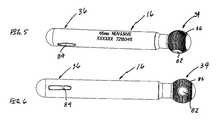
- FIG. 1is a perspective view of a spinal fixation system of the present invention incorporating (by way of example only) a single axis pedicle screw, a poly-axial pedicle screw, a spherical-ended rod member, and a transverse connector, each forming a unique and patentable aspect of the present invention;
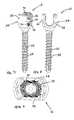
- FIG. 2is a perspective and exploded view of the spinal fixation system shown in FIG. 1 (sans transverse connector) illustrating the method of implanting the pedicle screws and rod member according to the present invention
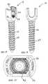
- FIG. 3is a perspective view of the spinal fixation system of the present (sans transverse connector) after implantation as shown in FIG. 2 ;
- FIG. 4is a perspective view of the transverse connector of the present invention being introduced onto the rod members of the spinal fixation system of the present invention
- FIGS. 5-6are side views of the rod member according to the present invention.
- FIGS. 7-9are perspective, side and top views, respectively, of a fixed angle pedicle screw assembly of the present invention, having a shaft diameter of 5.5 mm and a length of 45 mm;
- FIGS. 10-12are perspective, side and top views, respectively, of a fixed angle pedicle screw assembly of the present invention, having a shaft diameter of 6.5 mm and a length of 45 mm;
- FIGS. 13-15are perspective, side and top views, respectively, of a fixed angle pedicle screw assembly of the present invention, having a shaft diameter of 7.5 mm and a length of 45 mm;
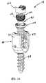
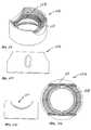
- FIG. 16is a perspective exploded view of a poly-axial pedicle screw assembly according to one embodiment of the present invention.
- FIGS. 17-19are perspective, side and top views, respectively, of a screw member forming part of the poly-axial pedicle screw system of the present invention.
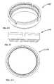
- FIGS. 20-22are perspective, side and top views, respectively, of a pivot ring forming part of the poly-axial pedicle screw system of the present invention.
- FIGS. 23-26are perspective, first side, second side, and top views, respectively, of a load ring forming part of the poly-axial pedicle screw system of the present invention.
- FIGS. 27-29are perspective, side and top views, respectively, of a transverse connector according to the present invention.
- FIG. 1is a perspective view of a spinal fixation system 10 of the present invention.
- the spinal fixation system 10is suitable for effecting fixation between adjacent vertebral levels within the spine.
- the spinal fixation system 10 of the present invention as shown in this embodimentincludes a pair single axis or “fixed” pedicle screw assemblies 12 , a pair of poly-axial pedicle screw assemblies 14 , a pair of cannulated rod members 16 , and a transverse connector 18 spanning between the pair of cannulated rod members 16 .
- Each of the single axis pedicle screw assembly 12 , poly-axial pedicle screw assembly 14 , cannulated rod member 16 , and transverse connector 18form a unique and patentable aspect of the present invention.
- the spinal fixation system 10is shown and described herein as a “single level” fixation system, meaning the single axis pedicle screw assemblies 12 will be fixed to a first vertebral body, the poly-axial pedicle screw assemblies 14 will be fixed to a second vertebral body (adjacent to the first vertebral body), the rod members 16 will be disposed on either side of (and generally parallel to) the midline of the spine, and the transverse connector 18 will span between the rod members 16 generally perpendicularly to the mid-line of the spine.
- spinal fixation system 10 of the present inventionmay be used in multi-level procedures without departing from the scope of the present invention.
- the spinal fixation system 10 of the present inventionmay comprise any number of variations of that shown without departing from the scope of the invention.
- the spinal fixation system 10may comprise four (4) of the single axis pedicle screw assemblies 12 , four (4) of the poly-axial pedicle screw assemblies 14 , and/or any combination of single and poly-axial pedicle screw assemblies 12 , 14 , in conjunction with the rod members 16 to effect spinal fixation.
- Each single axis pedicle screw assembly 12 of the present inventionincludes a screw member 20 having a shaft 22 and a housing 24 , as well as a locking screw 26 .
- the shaft 22 and housing 24are integrally formed as a unitary article such that the shaft 22 and housing 24 are in fixed relation, hence the term “single axis” to describe this type of pedicle screw assembly 12 according to the present invention.
- the shaft 22includes a thread 28 suitable for introduction into and purchase within bone.
- Each housing 24includes first and second branches 30 , 32 , which collectively form a generally “U” shaped area dimensioned to receive at least one of a ball portion 34 and/or a rod portion 36 (forming either end of the rod member 16 according to a further aspect of the present invention) and thereafter the locking screw 26 .
- each component of the fixed angle pedicle screw assembly 12is cannulated (i.e. it is equipped with a longitudinal lumen extends through the locking screw 26 and screw member 20 ) such that a K-wire may be used to guide the fixed angle pedicle screw assembly 12 into the patient.
- Each poly-axial pedicle screw assembly 14 of the present inventionincludes a screw member 40 , a housing 44 , and a locking screw 46 .
- the screw member 40includes a shaft 42 .
- the screw member 40 and housing 44are separate articles such that the angle of the housing 44 relative to the screw member 40 may be varied in any number of fashions prior to locking them together, hence the term “poly axial” to describe this type of pedicle screw assembly 14 according to the present invention.
- the shaft 42includes a thread 48 suitable for introduction into and purchase within bone.
- Each housing 44includes first and second branches 50 , 52 , which collectively form a generally “U” shaped area dimensioned to receive at least one of the ball portion 34 and/or rod portion 36 (forming either end of the rod member 16 according to a further aspect of the present invention) and thereafter the locking screw 46 .
- each component of the poly-axial pedicle screw assembly 14is cannulated (i.e. it is equipped with a longitudinal lumen extends through the locking screw 46 and screw member 40 ) such that a K-wire may be used to guide the poly-axial pedicle screw assembly 14 into the patient.
- the transverse connector 18 of the present inventionincludes a pair of rod clamping assemblies 60 capable of fixedly engaging regions on the respective rod members 16 , as well as a linkage assembly 62 extending between the rod clamping assemblies 60 .
- Each rod clamping assembly 60includes a top clamp member 64 , a bottom clamp member 66 (not shown), a clamp screw 68 , and a poly-axial pivot ring 70 (not shown).
- the linkage assembly 62includes a slotted link member 72 , a grooved link member 74 , and a link screw 76 .
- FIG. 2illustrates a method of using the spinal fixation system 10 according to one embodiment of the present invention.
- the fixed and poly-axial pedicle screw assemblies 12 , 14are preferably cannulated (i.e. a longitudinal lumen extends through the locking screws 26 , 46 and screw members 20 , 40 , respectively).
- each the pedicle screw assemblies 12 , 14 of the present inventionmay be advanced over a K-wire 80 and thereby guided into the patient.
- the K-wires 80may be used (with or without image guidance, such as X-ray and/or fluoroscopy systems) to target the location and trajectory to introduce the shafts 22 , 42 of the screw members 20 , 40 , respectively, into the pedicle of interest.
- the screw members 20 , 40may be advanced over a respective K-wire 80 until the distal end of the shafts 22 , 42 contact the pedicle, after which point the screw members 20 , 40 may be rotated about the K-wire 80 (e.g., by rotating the housings 24 , 44 via any suitable instrumentation) until the shafts 22 , 42 are introduced a desired depth into the pedicle and/or vertebral body.
- Thismay be preceded by any number of suitable preparatory steps, such as drilling and/or tapping a pilot hole to better accommodate the shafts 22 , 42 and/or threads 28 , 48 prior to the introduction of screw members 20 , 40 .
- rod members 16may thereafter be advanced into the patient for engagement with the pedicle screw assemblies 12 , 14 of the present invention.
- the rod member 16may be provided with one or more cannulations (e.g. cannulation 82 in the ball portion 34 and/or cannulation 84 in the rod region 36 ) such that one or more ends of the rod member 16 may be guided over a K-wire 80 and into a respective housing 24 , 44 .
- the locking screws 26 , 46may thereafter be introduced and engaged with the housings 24 , 44 . It may be desirable to adjust the position of the rod member 16 relative to the pedicle screw assemblies 12 , 14 according to a still further aspect of the present invention. More specifically, as will be discussed in greater detail below, the spherical nature of the ball region 34 of the rod member 16 will (prior to locking) allow it to rotate within the housing 24 . As such, the ball region 34 will be loosely disposed within the housing 24 such that the remainder of the rod member 16 may be angled therefrom in any number of desired manners (e.g. up, down, side-to-side and/or any variation thereof) depending upon the situation and need. This may advantageously facilitate positioning the rod region 36 into the housing 44 after the ball region 34 has already been positioned within housing 24 . Moreover, this may reduce if not eliminate the need to bend the rod member 16 as with traditional rod members of prior art pedicle screw systems.
- the locking screws 26 , 46may be secured or locked within the respective housing 24 , 44 via any number of suitable mechanisms, including but not limited to the manner shown, namely threading the exterior of the locking screws 26 , 46 and providing grooves along the interior of the housings 24 , 44 .
- the spinal fixation system 10 of the present inventionis suitable for both open and/or percutaneous procedures.
- any or all of the components of the pedicle screw systems 12 , 14 and rod member 16may be introduced without the assistance of a K-wire (and, for that matter, such components may be non-cannulated).
- both the pedicle screw assemblies 12 , 14 and rod member 16may be introduced percutaneously through the use of K-wire guidance. According to one embodiment, this may be accomplished by percutaneously (i.e.
- the ball portion 34 of the rod member 16will be locked in the housing 24 and the rod portion 36 will be locked in the housing 44 .
- the K-wires 80may then be withdrawn. Any number of suitable instruments may be employed to facilitate the above-identified steps, including but not limited to a screwdriver for screwing the locking screws 26 , 46 into the housings 24 , 44 .
- the spinal fixation system 10 of the present inventiononce implanted, will appear as shown in FIG. 3 .
- the transverse connector 18 of the present inventionmay thereafter be employed to establish a rigid coupling between the adjacent rod members 16 .
- the rod member 16 of the present inventionincludes the ball portion 34 at one end and the rod portion 36 at the other end.
- the ball portion 34 and/or the rod portion 36may be cannulated for purposes of accommodating a K-wire for guiding the rod member 16 into the patient, such as represented by cannulations 82 , 84 .
- the cannulation 82is preferably provided as a generally cylindrical lumen extending through the general center of the ball portion 34 such that it the center of the ball portion 34 may be guided directly into the spherical receiving area within the housing 24 (or housing 44 if the rod member 16 is reversed).
- the cannulation 84has a generally elongated shape to accommodate variations in the distance between the housing 24 and housing 44 , which may exist due to surgeon placement or other factors.
- the ball portion 34is equipped with a plurality of circumferential ridges 86 disposed generally perpendicularly to the longitudinal axis of the rod member 16 .
- these circumferential ridges 86cooperate with circumferential ridges provided within the housings 24 , 44 such that, when the ball portion 34 is locked therein, the two areas of circumferential ridges engage and meld together to prevent any rotation or movement therebetween.
- the rod member 16 of the present inventionmay be of any length suitable or desirable to connect two or more vertebrae, and may be generally provided in a range of 25-300 mm.
- the interior of the first and second branches 30 , 32are provided with grooves 90 to threadedly engage with threads provided on the exterior of the locking screw 26 .
- the grooves 90 and threads on the locking screw 26may be configured such that the first and second branches 30 , 32 are pulled together to prevent splaying during introduction of the locking screw 26 or due to use, such as by establishing a helical point-contact between the grooves 90 and threads on the locking screw 26 .
- the bottom of the housing 24is provided with a plurality of circumferential grooves 92 and 94 dimensioned to engage with the circumferential grooves 86 on the ball portion 34 of the rod member 16 .
- thisbolsters the purchase between the ball portion 34 and housing 26 such that the two are more effectively locked in position relative to one another after the locking screw 26 has been tightened.
- FIG. 8best illustrates the “U” shaped opening in the housing 24 , which may accommodate either the ball portion 34 and/or rod portion 36 of a rod member 16 .
- the thread 28is designed to have a uniform pitch regardless of the diameter of the shaft 22 .
- the thread 28has the same pitch for the 6.5 mm diameter shaft 22 as in the 5.5 mm diameter shaft 22 shown in FIGS. 7-9 .
- the thread 28has the same pitch for the 7.5 mm diameter shaft 22 as in the 5.5 mm diameter shaft 22 shown in FIGS. 7-9 and the 6.5 mm diameter shaft 22 shown in FIGS. 10-12 .
- the fixed angle pedicle screw assembly of the present inventionmay be of any length and width suitable or desirable to purchase the vertebrae, and may be generally provided with a width range of 5.5-7.5 mm and a length range of 30-50 mm.
- the screw member 40 and a housing 44are separate articles.
- the screw member 40includes a hemi-spherical head region 100 , which according to a preferred embodiment is equipped with a plurality of circumferential grooves 102 .
- the screw member 40is cannulated to receive a K-wire for guidance and includes a hex-type receiving area in the head region 100 to receive a screwdriver instrument.
- the poly-axial pedicle screw assembly 14is provided with a pivot ring 104 and a load ring 106 .
- the pivot ring 104is dimensioned to rest within a region within the bottom of the housing 44 and allow the head region 100 to pivot within the housing 44 prior to being locked in position.
- the load ring 106will rest on top of the head portion 100 of the screw member 40 and forms the receiving area for the ball portion 34 and/or rod portion 36 of the rod member 16 of the present invention.
- the load ring 106is equipped with a plurality of circumferential grooves 108 and 110 to engage and lock with the circumferential grooves 86 provided on at least the ball portion 34 .
- the poly-axial pedicle screw assembly of the present inventionmay be of any length and width suitable or desirable to purchase the vertebrae, and may be generally provided with a width range of 5.5-7.5 mm and a length range of 30-55 mm.
- the transverse connector 18 of the present inventionincludes a pair of rod clamping assemblies 60 capable of fixedly engaging regions on the respective rod members 16 , as well as a linkage assembly 62 extending between the rod clamping assemblies 60 .
- Each rod clamping assembly 60includes a top clamp member 64 , a bottom clamp member 66 (not shown), a clamp screw 68 , and a poly-axial pivot ring 70 (not shown).
- the linkage assembly 62includes a slotted link member 72 , a grooved link member 74 , and a link screw 76 .
- the transverse of the present inventionmay be of any length suitable or desirable to stabilize a pair of rods, and may be generally provided with a length range of 45-100 mm.
Landscapes
- Health & Medical Sciences (AREA)
- Orthopedic Medicine & Surgery (AREA)
- Neurology (AREA)
- Life Sciences & Earth Sciences (AREA)
- Surgery (AREA)
- Heart & Thoracic Surgery (AREA)
- Engineering & Computer Science (AREA)
- Biomedical Technology (AREA)
- Nuclear Medicine, Radiotherapy & Molecular Imaging (AREA)
- Medical Informatics (AREA)
- Molecular Biology (AREA)
- Animal Behavior & Ethology (AREA)
- General Health & Medical Sciences (AREA)
- Public Health (AREA)
- Veterinary Medicine (AREA)
- Surgical Instruments (AREA)
Abstract
Description
Claims (20)
Priority Applications (2)
| Application Number | Priority Date | Filing Date | Title |
|---|---|---|---|
| US11/031,506US7833251B1 (en) | 2004-01-06 | 2005-01-06 | System and method for performing spinal fixation |
| US12/535,671US8480712B1 (en) | 2004-01-06 | 2009-08-04 | System and method for performing spinal fixation |
Applications Claiming Priority (2)
| Application Number | Priority Date | Filing Date | Title |
|---|---|---|---|
| US53465004P | 2004-01-06 | 2004-01-06 | |
| US11/031,506US7833251B1 (en) | 2004-01-06 | 2005-01-06 | System and method for performing spinal fixation |
Related Child Applications (1)
| Application Number | Title | Priority Date | Filing Date |
|---|---|---|---|
| US12/535,671Continuation-In-PartUS8480712B1 (en) | 2004-01-06 | 2009-08-04 | System and method for performing spinal fixation |
Publications (1)
| Publication Number | Publication Date |
|---|---|
| US7833251B1true US7833251B1 (en) | 2010-11-16 |
Family
ID=43065826
Family Applications (1)
| Application Number | Title | Priority Date | Filing Date |
|---|---|---|---|
| US11/031,506Active2027-10-17US7833251B1 (en) | 2004-01-06 | 2005-01-06 | System and method for performing spinal fixation |
Country Status (1)
| Country | Link |
|---|---|
| US (1) | US7833251B1 (en) |
Cited By (89)
| Publication number | Priority date | Publication date | Assignee | Title |
|---|---|---|---|---|
| WO2006029373A1 (en) | 2004-09-08 | 2006-03-16 | Nuvasive, Inc. | Systems and methods for performing spinal fixation |
| US20080161854A1 (en)* | 2006-12-05 | 2008-07-03 | Spine Wave, Inc. | Dynamic Stabilization Devices and Methods |
| US20080183222A1 (en)* | 2004-07-21 | 2008-07-31 | Keun Ho Park | Pedicle screw and operating device thereof |
| US20100057137A1 (en)* | 2008-09-02 | 2010-03-04 | Heiges Bradley A | Modular Pedicle Screw System |
| US20100152576A1 (en)* | 2006-08-10 | 2010-06-17 | Cas Innovations Ag | Auxiliary device for establishing a mechanical connection between a medical implant and a tissue part of a patient |
| US7959679B2 (en) | 1999-08-18 | 2011-06-14 | Intrinsic Therapeutics, Inc. | Intervertebral anulus and nucleus augmentation |
| US7972337B2 (en) | 2005-12-28 | 2011-07-05 | Intrinsic Therapeutics, Inc. | Devices and methods for bone anchoring |
| US8002836B2 (en) | 1999-08-18 | 2011-08-23 | Intrinsic Therapeutics, Inc. | Method for the treatment of the intervertebral disc anulus |
| US8021425B2 (en)* | 1999-08-18 | 2011-09-20 | Intrinsic Therapeutics, Inc. | Versatile method of repairing an intervertebral disc |
| US20110276098A1 (en)* | 2010-05-05 | 2011-11-10 | Lutz Biedermann | Receiving part for receiving a rod for coupling the rod to a bone anchoring element, bone anchoring device, method and tool for assembling the same |
| US20120035670A1 (en)* | 2009-06-15 | 2012-02-09 | Jackson Roger P | Polyaxial bone anchors with pop-on shank, fully constrained friction fit retainer and lock and release insert |
| US20120143266A1 (en)* | 2009-06-15 | 2012-06-07 | Jackson Roger P | Polyaxial bone anchor with open planar retainer, pop-on shank and friction fit insert |
| US20120179212A1 (en)* | 2005-05-10 | 2012-07-12 | Jackson Roger P | Polyaxial bone anchor with compound articulation and pop-on shank |
| US8231678B2 (en) | 1999-08-18 | 2012-07-31 | Intrinsic Therapeutics, Inc. | Method of treating a herniated disc |
| US20120253400A1 (en)* | 2011-03-31 | 2012-10-04 | Corporation Spinelab AG | Vertebral column implant |
| US20120253401A1 (en)* | 2011-03-31 | 2012-10-04 | Spinelab Ag | Vertebral column implant for stabilization and stiffening of vertebral bodies of a vertebral column |
| US8323341B2 (en) | 2007-09-07 | 2012-12-04 | Intrinsic Therapeutics, Inc. | Impaction grafting for vertebral fusion |
| US20130085534A1 (en)* | 2011-09-30 | 2013-04-04 | Nicolas Hainard | Connectors for a secondary bone anchor |
| US8454612B2 (en) | 2007-09-07 | 2013-06-04 | Intrinsic Therapeutics, Inc. | Method for vertebral endplate reconstruction |
| US20140128918A1 (en)* | 2012-11-06 | 2014-05-08 | Michael Harper | Polyaxial Cross Connector |
| US20140135839A1 (en)* | 2012-11-09 | 2014-05-15 | Blackstone Medical, Inc. | Percutaneous modular head-to-head cross connector |
| US8758413B2 (en) | 2008-09-02 | 2014-06-24 | Bhdl Holdings, Llc | Method for selecting and installing a dynamic pedicle screw |
| US8852239B2 (en) | 2013-02-15 | 2014-10-07 | Roger P Jackson | Sagittal angle screw with integral shank and receiver |
| US8870928B2 (en) | 2002-09-06 | 2014-10-28 | Roger P. Jackson | Helical guide and advancement flange with radially loaded lip |
| US8911478B2 (en) | 2012-11-21 | 2014-12-16 | Roger P. Jackson | Splay control closure for open bone anchor |
| US8920475B1 (en) | 2011-01-07 | 2014-12-30 | Lanx, Inc. | Vertebral fixation system including torque mitigation |
| US8926670B2 (en) | 2003-06-18 | 2015-01-06 | Roger P. Jackson | Polyaxial bone screw assembly |
| US8926672B2 (en) | 2004-11-10 | 2015-01-06 | Roger P. Jackson | Splay control closure for open bone anchor |
| US8940024B2 (en) | 2007-07-31 | 2015-01-27 | Biedermann Technologies Gmbh & Co. Kg | Bone anchoring device |
| US8998960B2 (en) | 2004-11-10 | 2015-04-07 | Roger P. Jackson | Polyaxial bone screw with helically wound capture connection |
| US9144444B2 (en) | 2003-06-18 | 2015-09-29 | Roger P Jackson | Polyaxial bone anchor with helical capture connection, insert and dual locking assembly |
| US20150282847A1 (en)* | 2012-10-23 | 2015-10-08 | Charles R. Gordon | Method of Positioning Pedicle Screws and Spinal Rods and Apparatuses for the Same |
| US9161745B2 (en) | 2011-10-05 | 2015-10-20 | Mark A. Dodson | Modular retractor and related method |
| US9168069B2 (en) | 2009-06-15 | 2015-10-27 | Roger P. Jackson | Polyaxial bone anchor with pop-on shank and winged insert with lower skirt for engaging a friction fit retainer |
| US9308027B2 (en) | 2005-05-27 | 2016-04-12 | Roger P Jackson | Polyaxial bone screw with shank articulation pressure insert and method |
| US9393047B2 (en) | 2009-06-15 | 2016-07-19 | Roger P. Jackson | Polyaxial bone anchor with pop-on shank and friction fit retainer with low profile edge lock |
| US9439683B2 (en) | 2007-01-26 | 2016-09-13 | Roger P Jackson | Dynamic stabilization member with molded connection |
| US9451993B2 (en) | 2014-01-09 | 2016-09-27 | Roger P. Jackson | Bi-radial pop-on cervical bone anchor |
| US9451992B2 (en)* | 2010-12-01 | 2016-09-27 | Facet-Link Inc. | Variable angle bone screw fixation arrangement |
| US9504496B2 (en) | 2009-06-15 | 2016-11-29 | Roger P. Jackson | Polyaxial bone anchor with pop-on shank, friction fit retainer and winged insert |
| US9566092B2 (en) | 2013-10-29 | 2017-02-14 | Roger P. Jackson | Cervical bone anchor with collet retainer and outer locking sleeve |
| US9597119B2 (en) | 2014-06-04 | 2017-03-21 | Roger P. Jackson | Polyaxial bone anchor with polymer sleeve |
| US9603634B1 (en) | 2015-11-13 | 2017-03-28 | Amendia, Inc. | Percutaneous rod-to-rod cross connector |
| US9636146B2 (en) | 2012-01-10 | 2017-05-02 | Roger P. Jackson | Multi-start closures for open implants |
| US9662143B2 (en) | 2004-02-27 | 2017-05-30 | Roger P Jackson | Dynamic fixation assemblies with inner core and outer coil-like member |
| US9668771B2 (en) | 2009-06-15 | 2017-06-06 | Roger P Jackson | Soft stabilization assemblies with off-set connector |
| US9706947B2 (en) | 1999-08-18 | 2017-07-18 | Intrinsic Therapeutics, Inc. | Method of performing an anchor implantation procedure within a disc |
| US9717533B2 (en) | 2013-12-12 | 2017-08-01 | Roger P. Jackson | Bone anchor closure pivot-splay control flange form guide and advancement structure |
| US9883892B2 (en) | 2009-06-15 | 2018-02-06 | Roger P. Jackson | Polyaxial bone anchor with pop-on shank, friction fit retainer, winged insert and low profile edge lock |
| US9907574B2 (en)* | 2008-08-01 | 2018-03-06 | Roger P. Jackson | Polyaxial bone anchors with pop-on shank, friction fit fully restrained retainer, insert and tool receiving features |
| US9924975B2 (en) | 2014-10-21 | 2018-03-27 | Roger P. Jackson | Bone anchor having a snap-fit assembly |
| US9956006B2 (en) | 2009-06-15 | 2018-05-01 | Roger P. Jackson | Pivotal bone anchor with snap-on receiver and insert deployment |
| WO2018094320A1 (en)* | 2016-11-18 | 2018-05-24 | Garcia Bengochea Dr Javier | Implants and instruments for enhancing vertebral alignment and sagittal balance |
| US10039573B2 (en) | 2013-07-25 | 2018-08-07 | Amendia, Inc. | Percutaneous pedicle screw revision system |
| US10058354B2 (en) | 2013-01-28 | 2018-08-28 | Roger P. Jackson | Pivotal bone anchor assembly with frictional shank head seating surfaces |
| US10064658B2 (en) | 2014-06-04 | 2018-09-04 | Roger P. Jackson | Polyaxial bone anchor with insert guides |
| US10321833B2 (en) | 2016-10-05 | 2019-06-18 | Innovative Surgical Solutions. | Neural locating method |
| US10349983B2 (en) | 2003-05-22 | 2019-07-16 | Alphatec Spine, Inc. | Pivotal bone anchor assembly with biased bushing for pre-lock friction fit |
| US10363070B2 (en) | 2009-06-15 | 2019-07-30 | Roger P. Jackson | Pivotal bone anchor assemblies with pressure inserts and snap on articulating retainers |
| US10376209B2 (en) | 2013-09-20 | 2019-08-13 | Innovative Surgical Solutions, Llc | Neural locating method |
| US10376208B2 (en) | 2013-09-20 | 2019-08-13 | Innovative Surgical Solutions, Llc | Nerve mapping system |
| US10449002B2 (en) | 2013-09-20 | 2019-10-22 | Innovative Surgical Solutions, Llc | Method of mapping a nerve |
| US10478096B2 (en) | 2013-08-13 | 2019-11-19 | Innovative Surgical Solutions. | Neural event detection |
| US10478097B2 (en) | 2013-08-13 | 2019-11-19 | Innovative Surgical Solutions | Neural event detection |
| US10543021B2 (en) | 2014-10-21 | 2020-01-28 | Roger P. Jackson | Pivotal bone anchor assembly having an open ring positioner for a retainer |
| US10870002B2 (en) | 2018-10-12 | 2020-12-22 | DePuy Synthes Products, Inc. | Neuromuscular sensing device with multi-sensor array |
| US10869616B2 (en) | 2018-06-01 | 2020-12-22 | DePuy Synthes Products, Inc. | Neural event detection |
| US11229457B2 (en) | 2009-06-15 | 2022-01-25 | Roger P. Jackson | Pivotal bone anchor assembly with insert tool deployment |
| US11369417B1 (en) | 2021-06-08 | 2022-06-28 | Curiteva, Inc. | Modular polyaxial pedicle screw assembly with split ring |
| US11399777B2 (en) | 2019-09-27 | 2022-08-02 | DePuy Synthes Products, Inc. | Intraoperative neural monitoring system and method |
| US11419638B2 (en) | 2005-02-22 | 2022-08-23 | Roger P. Jackson | Pivotal bone anchor assembly with cannulated shank having a planar top surface surrounding an internal drive socket |
| US11464549B2 (en) | 2009-06-15 | 2022-10-11 | Roger P. Jackson | Pivotal bone anchor assembly with horizontal tool engagement grooves and insert with upright arms having flared outer portions |
| US11717328B2 (en) | 2007-01-22 | 2023-08-08 | Roger P. Jackson | Pivotal bone anchor assembly with twist-in-place insert |
| US11737789B2 (en) | 2004-11-23 | 2023-08-29 | Roger P. Jackson | Pivotal bone anchor assembly with pre-loaded retainer and bottom loaded cannulated screw having a planar top surface |
| US11751915B2 (en) | 2021-07-09 | 2023-09-12 | Roger P. Jackson | Modular spinal fixation system with bottom-loaded universal shank heads |
| US11864801B2 (en) | 2019-07-31 | 2024-01-09 | Seaspine, Inc. | Implantable universal connector |
| US11925392B2 (en) | 2007-05-23 | 2024-03-12 | Roger P. Jackson | Pivotal bone anchor assembly with bottom loaded spherical shank head having a planar upper surface |
| US12042185B2 (en) | 2010-05-14 | 2024-07-23 | Roger P. Jackson | Pivotal bone anchor assembly with resiliently biased friction fit insert |
| US12053217B2 (en) | 2019-12-17 | 2024-08-06 | Roger P. Jackson | Receiver assembly with rotation blocking side pockets for twist-in-place insert and method of assembly |
| US20240285322A1 (en)* | 2023-02-28 | 2024-08-29 | Globus Medical, Inc. | Orthopedic bone fasteners |
| US12082850B2 (en) | 2007-09-17 | 2024-09-10 | Roger P. Jackson | Pivotal bone anchor assembly having twist-in-place insert and receiver with pre-formed axial rotation insert stops |
| US12102357B2 (en) | 2005-02-22 | 2024-10-01 | Roger P. Jackson | Pivotal bone anchor assembly with cannulated shank having a planar top surface and method of assembly |
| US12137945B2 (en) | 2018-09-13 | 2024-11-12 | Roger P. Jackson | Pivotal bone anchor system with modular receiver sub-assemblies and universal bone anchors |
| US12167969B2 (en) | 2022-06-24 | 2024-12-17 | Nuvasive, Inc. | Resonating implant systems and methods |
| US12251138B2 (en) | 2014-10-21 | 2025-03-18 | Roger P. Jackson | Pivotal bone anchor assembly with biasing members for pre-lock friction fit |
| US12357348B2 (en) | 2005-09-30 | 2025-07-15 | Roger P. Jackson | Method of assembling a pivotal bone anchor assembly with press-in-place insert |
| US12376894B2 (en) | 2005-07-14 | 2025-08-05 | Roger P. Jackson | Pivotal bone anchor assembly with ring retainer and twist-in-place pressure insert |
| US12414801B2 (en) | 2022-11-03 | 2025-09-16 | Roger P. Jackson | Spinal fixation system with modular receiver sub-assemblies for connecting with bi-spherical universal shank heads |
| US12440245B2 (en) | 2023-09-06 | 2025-10-14 | Pivotable bone anchor assembly with independent provisional locking by insert compressing member |
Citations (87)
| Publication number | Priority date | Publication date | Assignee | Title |
|---|---|---|---|---|
| US4361141A (en) | 1979-07-27 | 1982-11-30 | Zimmer Usa, Inc. | Scoliosis transverse traction assembly |
| EP0128058A1 (en) | 1983-05-04 | 1984-12-12 | SOCIETE DE FABRICATION DE MATERIEL ORTHOPEDIQUE SOFAMOR Société à responsabilité limitée dite: | Spinal fixation device |
| FR2559378A1 (en) | 1984-02-09 | 1985-08-16 | Edwards Charles | SCREW AND DEVICE FOR FASTENING, AND METHOD FOR STRENGTHENING THE SACRUM REGION |
| US4771767A (en) | 1986-02-03 | 1988-09-20 | Acromed Corporation | Apparatus and method for maintaining vertebrae in a desired relationship |
| EP0283373A1 (en) | 1987-03-13 | 1988-09-21 | Societe De Fabrication De Materiel Orthopedique | Vertebral screw for an osteosynthesis device, especially for the lumbar and dorsal spine |
| DE3722590C1 (en) | 1987-07-08 | 1988-12-08 | Harms Juergen | Positioning device for stabilizing spinal segments |
| US4805602A (en) | 1986-11-03 | 1989-02-21 | Danninger Medical Technology | Transpedicular screw and rod system |
| FR2624720A1 (en) | 1987-12-21 | 1989-06-23 | Fabrication Materiel Orthopedi | Implant for osteosynthesis device, in particular for the spine |
| EP0348272A1 (en) | 1988-06-24 | 1989-12-27 | Societe De Fabrication De Materiel Orthopedique | Implant for a spiral osteosynthesis device, especially in traumatology |
| DE3841008A1 (en) | 1988-12-06 | 1990-06-07 | Heinrich Ulrich | Implant for correction of the spine |
| US4946458A (en) | 1986-04-25 | 1990-08-07 | Harms Juergen | Pedicle screw |
| US4998936A (en) | 1987-08-07 | 1991-03-12 | Mehdian Seyed M H | Apparatus for use in the treatment of spinal disorders |
| US5034011A (en) | 1990-08-09 | 1991-07-23 | Advanced Spine Fixation Systems Incorporated | Segmental instrumentation of the posterior spine |
| US5042982A (en) | 1987-07-08 | 1991-08-27 | Harms Juergen | Positioning device |
| DE9004960U1 (en) | 1990-05-02 | 1991-08-29 | Pfeil, Joachim, Dr.Med. | Halo fixator for the treatment of cervical spine diseases and injuries |
| US5084049A (en) | 1989-02-08 | 1992-01-28 | Acromed Corporation | Transverse connector for spinal column corrective devices |
| US5092866A (en) | 1989-02-03 | 1992-03-03 | Breard Francis H | Flexible inter-vertebral stabilizer as well as process and apparatus for determining or verifying its tension before installation on the spinal column |
| US5092867A (en) | 1988-07-13 | 1992-03-03 | Harms Juergen | Correction and supporting apparatus, in particular for the spinal column |
| US5129388A (en) | 1989-02-09 | 1992-07-14 | Vignaud Jean Louis | Device for supporting the spinal column |
| US5176680A (en) | 1990-02-08 | 1993-01-05 | Vignaud Jean Louis | Device for the adjustable fixing of spinal osteosynthesis rods |
| US5196013A (en) | 1989-11-03 | 1993-03-23 | Harms Juergen | Pedicel screw and correcting and supporting apparatus comprising such screw |
| US5207678A (en) | 1989-07-20 | 1993-05-04 | Prufer | Pedicle screw and receiver member therefore |
| US5234431A (en)* | 1991-04-03 | 1993-08-10 | Waldemar Link Gmbh & Co. | Bone plate arrangement |
| US5261907A (en) | 1991-05-17 | 1993-11-16 | Vignaud Jean L | Interconnecting device able to lock spinal osteosynthesis fasteners |
| US5275600A (en) | 1992-10-05 | 1994-01-04 | Zimmer, Inc. | Telescoping rod to rod coupler for a spinal system |
| US5312405A (en) | 1992-07-06 | 1994-05-17 | Zimmer, Inc. | Spinal rod coupler |
| US5330473A (en) | 1993-03-04 | 1994-07-19 | Advanced Spine Fixation Systems, Inc. | Branch connector for spinal fixation systems |
| US5375823A (en) | 1992-06-25 | 1994-12-27 | Societe Psi | Application of an improved damper to an intervertebral stabilization device |
| US5387213A (en) | 1991-02-05 | 1995-02-07 | Safir S.A.R.L. | Osseous surgical implant particularly for an intervertebral stabilizer |
| US5466237A (en) | 1993-11-19 | 1995-11-14 | Cross Medical Products, Inc. | Variable locking stabilizer anchor seat and screw |
| US5474555A (en) | 1990-04-26 | 1995-12-12 | Cross Medical Products | Spinal implant system |
| US5478340A (en) | 1992-01-31 | 1995-12-26 | Kluger; Patrick | Vertebral column implant and repositioning instrument |
| US5480401A (en) | 1993-02-17 | 1996-01-02 | Psi | Extra-discal inter-vertebral prosthesis for controlling the variations of the inter-vertebral distance by means of a double damper |
| US5505731A (en)* | 1993-09-01 | 1996-04-09 | Tornier Sa | Screw for lumbar-sacral fixator |
| US5536268A (en) | 1992-12-23 | 1996-07-16 | Plus Endoprothetik Ag | System for osteosynthesis at the vertebral column, connecting element for such a system and tool for its placement and removal |
| US5540688A (en) | 1991-05-30 | 1996-07-30 | Societe "Psi" | Intervertebral stabilization device incorporating dampers |
| US5545163A (en)* | 1991-07-15 | 1996-08-13 | Danek Medical, Inc. | Spinal fixation system |
| US5545166A (en) | 1994-07-14 | 1996-08-13 | Advanced Spine Fixation Systems, Incorporated | Spinal segmental reduction derotational fixation system |
| US5607425A (en) | 1993-10-08 | 1997-03-04 | Rogozinski; Chaim | Apparatus, method and system for the treatment of spinal conditions |
| US5630816A (en) | 1995-05-01 | 1997-05-20 | Kambin; Parviz | Double barrel spinal fixation system and method |
| WO1997022306A1 (en) | 1995-12-20 | 1997-06-26 | Smith & Nephew Inc. | Osteosynthesis apparatus |
| US5643264A (en) | 1995-09-13 | 1997-07-01 | Danek Medical, Inc. | Iliac screw |
| US5645544A (en) | 1995-09-13 | 1997-07-08 | Danek Medical, Inc. | Variable angle extension rod |
| US5665122A (en) | 1995-01-31 | 1997-09-09 | Kambin; Parviz | Expandable intervertebral cage and surgical method |
| US5667508A (en) | 1996-05-01 | 1997-09-16 | Fastenetix, Llc | Unitary locking cap for use with a pedicle screw |
| US5669911A (en) | 1995-04-13 | 1997-09-23 | Fastenetix, L.L.C. | Polyaxial pedicle screw |
| US5672176A (en) | 1995-03-15 | 1997-09-30 | Biedermann; Lutz | Anchoring member |
| US5676665A (en) | 1995-06-23 | 1997-10-14 | Bryan; Donald W. | Spinal fixation apparatus and method |
| US5704936A (en) | 1992-04-10 | 1998-01-06 | Eurosurgical | Spinal osteosynthesis device |
| US5716355A (en) | 1995-04-10 | 1998-02-10 | Sofamor Danek Group, Inc. | Transverse connection for spinal rods |
| US5725527A (en) | 1992-09-10 | 1998-03-10 | Biedermann Motech Gmbh | Anchoring member |
| US5776135A (en) | 1996-12-23 | 1998-07-07 | Third Millennium Engineering, Llc | Side mounted polyaxial pedicle screw |
| US5800435A (en) | 1996-10-09 | 1998-09-01 | Techsys, Llc | Modular spinal plate for use with modular polyaxial locking pedicle screws |
| US5863293A (en) | 1996-10-18 | 1999-01-26 | Spinal Innovations | Spinal implant fixation assembly |
| US5873878A (en) | 1996-04-30 | 1999-02-23 | Harms; Juergen | Anchoring member |
| US5928237A (en) | 1994-03-29 | 1999-07-27 | Sdgi Holdings, Inc. | Variable angle surgical cable crimp assembly and method |
| US5928232A (en) | 1994-11-16 | 1999-07-27 | Advanced Spine Fixation Systems, Incorporated | Spinal fixation system |
| US5938663A (en) | 1995-03-06 | 1999-08-17 | Stryker France, S.A. | Spinal instruments, particularly for a rod |
| US5944720A (en) | 1998-03-25 | 1999-08-31 | Lipton; Glenn E | Posterior spinal fixation system |
| US5944719A (en) | 1998-11-10 | 1999-08-31 | Millennium Devices, L.L.C. | External fixator |
| US5947966A (en) | 1995-06-06 | 1999-09-07 | Sdgi Holdings, Inc. | Device for linking adjacent rods in spinal instrumentation |
| US5951555A (en) | 1996-03-27 | 1999-09-14 | Rehak; Lubos | Device for the correction of spinal deformities |
| US5954722A (en) | 1997-07-29 | 1999-09-21 | Depuy Acromed, Inc. | Polyaxial locking plate |
| US5954725A (en) | 1996-11-07 | 1999-09-21 | Sdgi Holdings, Inc. | Multi-angle bone screw assembly using shape memory technology |
| US5961516A (en) | 1996-08-01 | 1999-10-05 | Graf; Henry | Device for mechanically connecting and assisting vertebrae with respect to one another |
| US5980523A (en) | 1998-01-08 | 1999-11-09 | Jackson; Roger | Transverse connectors for spinal rods |
| DE9219204U1 (en) | 1992-01-17 | 1999-12-16 | Ulrich, Heinrich, 89075 Ulm | Peg plate |
| US6030389A (en) | 1997-08-04 | 2000-02-29 | Spinal Concepts, Inc. | System and method for stabilizing the human spine with a bone plate |
| US6074391A (en)* | 1997-06-16 | 2000-06-13 | Howmedica Gmbh | Receiving part for a retaining component of a vertebral column implant |
| US6113600A (en) | 1995-06-06 | 2000-09-05 | Denek Medical, Inc. | Device for linking adjacent rods in spinal instrumentation |
| US6139548A (en) | 1995-10-30 | 2000-10-31 | Spinal Concepts, Inc. | Sliding shaft variable length cross-link device for use with dual rod apparatus |
| EP1072228A1 (en) | 1999-07-27 | 2001-01-31 | Société Etudes et Developpements S.E.D. | Implantable intervertebral connector device |
| US6190388B1 (en) | 1995-06-07 | 2001-02-20 | Gary K. Michelson | Anterior spinal instrumentation and method for implantation and revision |
| US6217578B1 (en) | 1999-10-19 | 2001-04-17 | Stryker Spine S.A. | Spinal cross connector |
| US6224598B1 (en)* | 2000-02-16 | 2001-05-01 | Roger P. Jackson | Bone screw threaded plug closure with central set screw |
| US6234705B1 (en) | 1999-04-06 | 2001-05-22 | Synthes (Usa) | Transconnector for coupling spinal rods |
| US6241730B1 (en) | 1997-11-26 | 2001-06-05 | Scient'x (Societe A Responsabilite Limitee) | Intervertebral link device capable of axial and angular displacement |
| US6264658B1 (en) | 1998-07-06 | 2001-07-24 | Solco Surgical Instruments Co., Ltd. | Spine fixing apparatus |
| US6267765B1 (en)* | 1997-06-03 | 2001-07-31 | Jean Taylor | Multidirectional adaptable vertebral osteosyntsis device with reduced space requirement |
| US6273914B1 (en)* | 1995-09-28 | 2001-08-14 | Sparta, Inc. | Spinal implant |
| US6283967B1 (en) | 1999-12-17 | 2001-09-04 | Synthes (U.S.A.) | Transconnector for coupling spinal rods |
| US6296644B1 (en) | 1998-08-26 | 2001-10-02 | Jean Saurat | Spinal instrumentation system with articulated modules |
| US20010034521A1 (en) | 2000-02-16 | 2001-10-25 | Bailey Kirk J. | Method and system for spinal fixation |
| US6325802B1 (en) | 1992-08-12 | 2001-12-04 | Synthes (U.S.A.) | Spinal fixation element |
| US20040260287A1 (en) | 2001-03-26 | 2004-12-23 | Nuvasive, Inc. | Spinal alignment system and related methods |
| US20050010217A1 (en)* | 2003-07-07 | 2005-01-13 | Dalton Brian E. | Spinal stabilization implant and method of application |
| US6899714B2 (en)* | 2001-10-03 | 2005-05-31 | Vaughan Medical Technologies, Inc. | Vertebral stabilization assembly and method |
- 2005
- 2005-01-06USUS11/031,506patent/US7833251B1/enactiveActive
Patent Citations (93)
| Publication number | Priority date | Publication date | Assignee | Title |
|---|---|---|---|---|
| US4361141A (en) | 1979-07-27 | 1982-11-30 | Zimmer Usa, Inc. | Scoliosis transverse traction assembly |
| EP0128058A1 (en) | 1983-05-04 | 1984-12-12 | SOCIETE DE FABRICATION DE MATERIEL ORTHOPEDIQUE SOFAMOR Société à responsabilité limitée dite: | Spinal fixation device |
| FR2559378A1 (en) | 1984-02-09 | 1985-08-16 | Edwards Charles | SCREW AND DEVICE FOR FASTENING, AND METHOD FOR STRENGTHENING THE SACRUM REGION |
| US4771767A (en) | 1986-02-03 | 1988-09-20 | Acromed Corporation | Apparatus and method for maintaining vertebrae in a desired relationship |
| US4946458A (en) | 1986-04-25 | 1990-08-07 | Harms Juergen | Pedicle screw |
| US4805602A (en) | 1986-11-03 | 1989-02-21 | Danninger Medical Technology | Transpedicular screw and rod system |
| EP0283373A1 (en) | 1987-03-13 | 1988-09-21 | Societe De Fabrication De Materiel Orthopedique | Vertebral screw for an osteosynthesis device, especially for the lumbar and dorsal spine |
| DE3722590C1 (en) | 1987-07-08 | 1988-12-08 | Harms Juergen | Positioning device for stabilizing spinal segments |
| US5042982A (en) | 1987-07-08 | 1991-08-27 | Harms Juergen | Positioning device |
| US4998936A (en) | 1987-08-07 | 1991-03-12 | Mehdian Seyed M H | Apparatus for use in the treatment of spinal disorders |
| FR2624720A1 (en) | 1987-12-21 | 1989-06-23 | Fabrication Materiel Orthopedi | Implant for osteosynthesis device, in particular for the spine |
| EP0348272A1 (en) | 1988-06-24 | 1989-12-27 | Societe De Fabrication De Materiel Orthopedique | Implant for a spiral osteosynthesis device, especially in traumatology |
| US5092867A (en) | 1988-07-13 | 1992-03-03 | Harms Juergen | Correction and supporting apparatus, in particular for the spinal column |
| DE3841008A1 (en) | 1988-12-06 | 1990-06-07 | Heinrich Ulrich | Implant for correction of the spine |
| US5092866A (en) | 1989-02-03 | 1992-03-03 | Breard Francis H | Flexible inter-vertebral stabilizer as well as process and apparatus for determining or verifying its tension before installation on the spinal column |
| US5084049A (en) | 1989-02-08 | 1992-01-28 | Acromed Corporation | Transverse connector for spinal column corrective devices |
| US5129388A (en) | 1989-02-09 | 1992-07-14 | Vignaud Jean Louis | Device for supporting the spinal column |
| US5207678A (en) | 1989-07-20 | 1993-05-04 | Prufer | Pedicle screw and receiver member therefore |
| US5196013A (en) | 1989-11-03 | 1993-03-23 | Harms Juergen | Pedicel screw and correcting and supporting apparatus comprising such screw |
| US5176680A (en) | 1990-02-08 | 1993-01-05 | Vignaud Jean Louis | Device for the adjustable fixing of spinal osteosynthesis rods |
| US5624442A (en) | 1990-04-26 | 1997-04-29 | Cross Medical Products, Inc. | Transverse link for use with a spinal implant system |
| US5474555A (en) | 1990-04-26 | 1995-12-12 | Cross Medical Products | Spinal implant system |
| DE9004960U1 (en) | 1990-05-02 | 1991-08-29 | Pfeil, Joachim, Dr.Med. | Halo fixator for the treatment of cervical spine diseases and injuries |
| US5034011A (en) | 1990-08-09 | 1991-07-23 | Advanced Spine Fixation Systems Incorporated | Segmental instrumentation of the posterior spine |
| US5387213A (en) | 1991-02-05 | 1995-02-07 | Safir S.A.R.L. | Osseous surgical implant particularly for an intervertebral stabilizer |
| US5234431A (en)* | 1991-04-03 | 1993-08-10 | Waldemar Link Gmbh & Co. | Bone plate arrangement |
| US5261907A (en) | 1991-05-17 | 1993-11-16 | Vignaud Jean L | Interconnecting device able to lock spinal osteosynthesis fasteners |
| US5540688A (en) | 1991-05-30 | 1996-07-30 | Societe "Psi" | Intervertebral stabilization device incorporating dampers |
| US5545163A (en)* | 1991-07-15 | 1996-08-13 | Danek Medical, Inc. | Spinal fixation system |
| DE9219204U1 (en) | 1992-01-17 | 1999-12-16 | Ulrich, Heinrich, 89075 Ulm | Peg plate |
| US5478340A (en) | 1992-01-31 | 1995-12-26 | Kluger; Patrick | Vertebral column implant and repositioning instrument |
| US5704936A (en) | 1992-04-10 | 1998-01-06 | Eurosurgical | Spinal osteosynthesis device |
| US5375823A (en) | 1992-06-25 | 1994-12-27 | Societe Psi | Application of an improved damper to an intervertebral stabilization device |
| US5312405A (en) | 1992-07-06 | 1994-05-17 | Zimmer, Inc. | Spinal rod coupler |
| US6325802B1 (en) | 1992-08-12 | 2001-12-04 | Synthes (U.S.A.) | Spinal fixation element |
| US5725527A (en) | 1992-09-10 | 1998-03-10 | Biedermann Motech Gmbh | Anchoring member |
| US5275600A (en) | 1992-10-05 | 1994-01-04 | Zimmer, Inc. | Telescoping rod to rod coupler for a spinal system |
| US5536268A (en) | 1992-12-23 | 1996-07-16 | Plus Endoprothetik Ag | System for osteosynthesis at the vertebral column, connecting element for such a system and tool for its placement and removal |
| US5480401A (en) | 1993-02-17 | 1996-01-02 | Psi | Extra-discal inter-vertebral prosthesis for controlling the variations of the inter-vertebral distance by means of a double damper |
| US5330473A (en) | 1993-03-04 | 1994-07-19 | Advanced Spine Fixation Systems, Inc. | Branch connector for spinal fixation systems |
| US5505731A (en)* | 1993-09-01 | 1996-04-09 | Tornier Sa | Screw for lumbar-sacral fixator |
| US6379354B1 (en) | 1993-10-08 | 2002-04-30 | Chaim Rogozinski | Spinal implant and method |
| US5607425A (en) | 1993-10-08 | 1997-03-04 | Rogozinski; Chaim | Apparatus, method and system for the treatment of spinal conditions |
| US5466237A (en) | 1993-11-19 | 1995-11-14 | Cross Medical Products, Inc. | Variable locking stabilizer anchor seat and screw |
| US5928237A (en) | 1994-03-29 | 1999-07-27 | Sdgi Holdings, Inc. | Variable angle surgical cable crimp assembly and method |
| US5545166A (en) | 1994-07-14 | 1996-08-13 | Advanced Spine Fixation Systems, Incorporated | Spinal segmental reduction derotational fixation system |
| US5928232A (en) | 1994-11-16 | 1999-07-27 | Advanced Spine Fixation Systems, Incorporated | Spinal fixation system |
| US5665122A (en) | 1995-01-31 | 1997-09-09 | Kambin; Parviz | Expandable intervertebral cage and surgical method |
| US5938663A (en) | 1995-03-06 | 1999-08-17 | Stryker France, S.A. | Spinal instruments, particularly for a rod |
| US5672176A (en) | 1995-03-15 | 1997-09-30 | Biedermann; Lutz | Anchoring member |
| US5716355A (en) | 1995-04-10 | 1998-02-10 | Sofamor Danek Group, Inc. | Transverse connection for spinal rods |
| US5669911A (en) | 1995-04-13 | 1997-09-23 | Fastenetix, L.L.C. | Polyaxial pedicle screw |
| US5690630A (en) | 1995-04-13 | 1997-11-25 | Fastenetix, Llc | Polyaxial pedicle screw |
| US5630816A (en) | 1995-05-01 | 1997-05-20 | Kambin; Parviz | Double barrel spinal fixation system and method |
| US6113600A (en) | 1995-06-06 | 2000-09-05 | Denek Medical, Inc. | Device for linking adjacent rods in spinal instrumentation |
| US6136003A (en) | 1995-06-06 | 2000-10-24 | Sdgi Holdings, Inc. | Device for linking adjacent rods in spinal instrumentation |
| US5947966A (en) | 1995-06-06 | 1999-09-07 | Sdgi Holdings, Inc. | Device for linking adjacent rods in spinal instrumentation |
| US6190388B1 (en) | 1995-06-07 | 2001-02-20 | Gary K. Michelson | Anterior spinal instrumentation and method for implantation and revision |
| US5676665A (en) | 1995-06-23 | 1997-10-14 | Bryan; Donald W. | Spinal fixation apparatus and method |
| US5645544A (en) | 1995-09-13 | 1997-07-08 | Danek Medical, Inc. | Variable angle extension rod |
| US5643264A (en) | 1995-09-13 | 1997-07-01 | Danek Medical, Inc. | Iliac screw |
| US6273914B1 (en)* | 1995-09-28 | 2001-08-14 | Sparta, Inc. | Spinal implant |
| US6139548A (en) | 1995-10-30 | 2000-10-31 | Spinal Concepts, Inc. | Sliding shaft variable length cross-link device for use with dual rod apparatus |
| WO1997022306A1 (en) | 1995-12-20 | 1997-06-26 | Smith & Nephew Inc. | Osteosynthesis apparatus |
| US5951555A (en) | 1996-03-27 | 1999-09-14 | Rehak; Lubos | Device for the correction of spinal deformities |
| US5873878A (en) | 1996-04-30 | 1999-02-23 | Harms; Juergen | Anchoring member |
| US5667508A (en) | 1996-05-01 | 1997-09-16 | Fastenetix, Llc | Unitary locking cap for use with a pedicle screw |
| US5961516A (en) | 1996-08-01 | 1999-10-05 | Graf; Henry | Device for mechanically connecting and assisting vertebrae with respect to one another |
| US5800435A (en) | 1996-10-09 | 1998-09-01 | Techsys, Llc | Modular spinal plate for use with modular polyaxial locking pedicle screws |
| US5863293A (en) | 1996-10-18 | 1999-01-26 | Spinal Innovations | Spinal implant fixation assembly |
| US5954725A (en) | 1996-11-07 | 1999-09-21 | Sdgi Holdings, Inc. | Multi-angle bone screw assembly using shape memory technology |
| US6063089A (en) | 1996-12-23 | 2000-05-16 | Spinal Concepts, Inc. | Side mounted polyaxial pedicle screw |
| US5776135A (en) | 1996-12-23 | 1998-07-07 | Third Millennium Engineering, Llc | Side mounted polyaxial pedicle screw |
| US6267765B1 (en)* | 1997-06-03 | 2001-07-31 | Jean Taylor | Multidirectional adaptable vertebral osteosyntsis device with reduced space requirement |
| US6074391A (en)* | 1997-06-16 | 2000-06-13 | Howmedica Gmbh | Receiving part for a retaining component of a vertebral column implant |
| US5954722A (en) | 1997-07-29 | 1999-09-21 | Depuy Acromed, Inc. | Polyaxial locking plate |
| US6030389A (en) | 1997-08-04 | 2000-02-29 | Spinal Concepts, Inc. | System and method for stabilizing the human spine with a bone plate |
| US6241730B1 (en) | 1997-11-26 | 2001-06-05 | Scient'x (Societe A Responsabilite Limitee) | Intervertebral link device capable of axial and angular displacement |
| US5980523A (en) | 1998-01-08 | 1999-11-09 | Jackson; Roger | Transverse connectors for spinal rods |
| US5944720A (en) | 1998-03-25 | 1999-08-31 | Lipton; Glenn E | Posterior spinal fixation system |
| US6264658B1 (en) | 1998-07-06 | 2001-07-24 | Solco Surgical Instruments Co., Ltd. | Spine fixing apparatus |
| US6296644B1 (en) | 1998-08-26 | 2001-10-02 | Jean Saurat | Spinal instrumentation system with articulated modules |
| US5944719A (en) | 1998-11-10 | 1999-08-31 | Millennium Devices, L.L.C. | External fixator |
| US6306137B2 (en) | 1999-04-06 | 2001-10-23 | Synthes (U.S.A.) | Transconnector for coupling spinal rods |
| US6234705B1 (en) | 1999-04-06 | 2001-05-22 | Synthes (Usa) | Transconnector for coupling spinal rods |
| EP1072228A1 (en) | 1999-07-27 | 2001-01-31 | Société Etudes et Developpements S.E.D. | Implantable intervertebral connector device |
| US6217578B1 (en) | 1999-10-19 | 2001-04-17 | Stryker Spine S.A. | Spinal cross connector |
| US6283967B1 (en) | 1999-12-17 | 2001-09-04 | Synthes (U.S.A.) | Transconnector for coupling spinal rods |
| US20010034521A1 (en) | 2000-02-16 | 2001-10-25 | Bailey Kirk J. | Method and system for spinal fixation |
| US6224598B1 (en)* | 2000-02-16 | 2001-05-01 | Roger P. Jackson | Bone screw threaded plug closure with central set screw |
| US20040260287A1 (en) | 2001-03-26 | 2004-12-23 | Nuvasive, Inc. | Spinal alignment system and related methods |
| US6899714B2 (en)* | 2001-10-03 | 2005-05-31 | Vaughan Medical Technologies, Inc. | Vertebral stabilization assembly and method |
| US20050010217A1 (en)* | 2003-07-07 | 2005-01-13 | Dalton Brian E. | Spinal stabilization implant and method of application |
Non-Patent Citations (8)
| Title |
|---|
| Beadling, "Harrington put the steel in spinal fixation",Orthopedics Today, (Jun. 2000). |
| Dipreta, "The Illiac Nail/Screw: A Modified . . .", Am. Acad. of Ortho. Surg., 67th mtg., PE184, (Mar. 19, 2000). |
| Ebrahim, "Posterior Lateral Mass Screw Fixation . . .", U.P.O.J., vol. 12, (Spring 1999),66-72. |
| Erickson, "Biomechanical Assessment of . . .", Am. Acad. of Ortho. Surg., 2002 mtg., P217, (Mar. 13, 2002). |
| Pham, "Upper Cervical Spine Surgery in . . .", Joint Bone Spine 2000, 67, (2000),434-440. |
| Sanders, "Treating, managing spinal deformity in young patients", Orthopedics today, (Jul. 2001). |
| Spiegel, "Anterior instrumentation in the Treatment . . .", U.P.O.J., vol. 11, (Spring 1998), 19-26. |
| Wood, "Torsional Rigidity of Scoliosis Constructs", Am. Acad. of Ortho. Surg., PE123, (Feb. 4, 1999). |
Cited By (190)
| Publication number | Priority date | Publication date | Assignee | Title |
|---|---|---|---|---|
| US8105384B2 (en) | 1999-08-18 | 2012-01-31 | Intrinsic Therapeutics, Inc. | Weakened anulus repair |
| US9706947B2 (en) | 1999-08-18 | 2017-07-18 | Intrinsic Therapeutics, Inc. | Method of performing an anchor implantation procedure within a disc |
| US8409284B2 (en) | 1999-08-18 | 2013-04-02 | Intrinsic Therapeutics, Inc. | Methods of repairing herniated segments in the disc |
| US8257437B2 (en) | 1999-08-18 | 2012-09-04 | Intrinsic Therapeutics, Inc. | Methods of intervertebral disc augmentation |
| US8231678B2 (en) | 1999-08-18 | 2012-07-31 | Intrinsic Therapeutics, Inc. | Method of treating a herniated disc |
| US7959679B2 (en) | 1999-08-18 | 2011-06-14 | Intrinsic Therapeutics, Inc. | Intervertebral anulus and nucleus augmentation |
| US8025698B2 (en) | 1999-08-18 | 2011-09-27 | Intrinsic Therapeutics, Inc. | Method of rehabilitating an anulus fibrosus |
| US9333087B2 (en) | 1999-08-18 | 2016-05-10 | Intrinsic Therapeutics, Inc. | Herniated disc repair |
| US7998213B2 (en) | 1999-08-18 | 2011-08-16 | Intrinsic Therapeutics, Inc. | Intervertebral disc herniation repair |
| US8002836B2 (en) | 1999-08-18 | 2011-08-23 | Intrinsic Therapeutics, Inc. | Method for the treatment of the intervertebral disc anulus |
| US8021425B2 (en)* | 1999-08-18 | 2011-09-20 | Intrinsic Therapeutics, Inc. | Versatile method of repairing an intervertebral disc |
| US8870928B2 (en) | 2002-09-06 | 2014-10-28 | Roger P. Jackson | Helical guide and advancement flange with radially loaded lip |
| US10349983B2 (en) | 2003-05-22 | 2019-07-16 | Alphatec Spine, Inc. | Pivotal bone anchor assembly with biased bushing for pre-lock friction fit |
| US9144444B2 (en) | 2003-06-18 | 2015-09-29 | Roger P Jackson | Polyaxial bone anchor with helical capture connection, insert and dual locking assembly |
| US8926670B2 (en) | 2003-06-18 | 2015-01-06 | Roger P. Jackson | Polyaxial bone screw assembly |
| US8936623B2 (en) | 2003-06-18 | 2015-01-20 | Roger P. Jackson | Polyaxial bone screw assembly |
| US9662143B2 (en) | 2004-02-27 | 2017-05-30 | Roger P Jackson | Dynamic fixation assemblies with inner core and outer coil-like member |
| US20080183222A1 (en)* | 2004-07-21 | 2008-07-31 | Keun Ho Park | Pedicle screw and operating device thereof |
| US8197522B2 (en)* | 2004-07-21 | 2012-06-12 | Solco Biomedical Co., Ltd. | Pedicle screw and operating device thereof |
| WO2006029373A1 (en) | 2004-09-08 | 2006-03-16 | Nuvasive, Inc. | Systems and methods for performing spinal fixation |
| US9743957B2 (en) | 2004-11-10 | 2017-08-29 | Roger P. Jackson | Polyaxial bone screw with shank articulation pressure insert and method |
| US8998960B2 (en) | 2004-11-10 | 2015-04-07 | Roger P. Jackson | Polyaxial bone screw with helically wound capture connection |
| US8926672B2 (en) | 2004-11-10 | 2015-01-06 | Roger P. Jackson | Splay control closure for open bone anchor |
| US11147591B2 (en) | 2004-11-10 | 2021-10-19 | Roger P Jackson | Pivotal bone anchor receiver assembly with threaded closure |
| US9522021B2 (en) | 2004-11-23 | 2016-12-20 | Roger P. Jackson | Polyaxial bone anchor with retainer with notch for mono-axial motion |
| US12262920B2 (en) | 2004-11-23 | 2025-04-01 | Roger P. Jackson | Method of assembling a bottom-loaded pivotal bone anchor assembly with compression insert and two-part shank retainer |
| US11737789B2 (en) | 2004-11-23 | 2023-08-29 | Roger P. Jackson | Pivotal bone anchor assembly with pre-loaded retainer and bottom loaded cannulated screw having a planar top surface |
| US12102357B2 (en) | 2005-02-22 | 2024-10-01 | Roger P. Jackson | Pivotal bone anchor assembly with cannulated shank having a planar top surface and method of assembly |
| US11419638B2 (en) | 2005-02-22 | 2022-08-23 | Roger P. Jackson | Pivotal bone anchor assembly with cannulated shank having a planar top surface surrounding an internal drive socket |
| US20120179212A1 (en)* | 2005-05-10 | 2012-07-12 | Jackson Roger P | Polyaxial bone anchor with compound articulation and pop-on shank |
| US10219837B2 (en) | 2005-05-10 | 2019-03-05 | Roger P. Jackson | Bone anchor receiver with longitudinally extending tool attachment structures |
| US10987137B2 (en) | 2005-05-10 | 2021-04-27 | Roger P. Jackson | Pivotal bone anchor assembly with independent lock via insert compressing tool |
| US10194951B2 (en)* | 2005-05-10 | 2019-02-05 | Roger P. Jackson | Polyaxial bone anchor with compound articulation and pop-on shank |
| US9308027B2 (en) | 2005-05-27 | 2016-04-12 | Roger P Jackson | Polyaxial bone screw with shank articulation pressure insert and method |
| US12185984B2 (en) | 2005-05-27 | 2025-01-07 | Roger P. Jackson | Method of assembling a pivotal bone anchor screw with insert tool deployment |
| US12376894B2 (en) | 2005-07-14 | 2025-08-05 | Roger P. Jackson | Pivotal bone anchor assembly with ring retainer and twist-in-place pressure insert |
| US12357348B2 (en) | 2005-09-30 | 2025-07-15 | Roger P. Jackson | Method of assembling a pivotal bone anchor assembly with press-in-place insert |
| US11957386B2 (en) | 2005-09-30 | 2024-04-16 | Roger P. Jackson | Pivotal bone anchor assembly having a downwardly-displaceable snap-in-place insert and method of assembly |
| US7972337B2 (en) | 2005-12-28 | 2011-07-05 | Intrinsic Therapeutics, Inc. | Devices and methods for bone anchoring |
| US9039741B2 (en) | 2005-12-28 | 2015-05-26 | Intrinsic Therapeutics, Inc. | Bone anchor systems |
| US8394146B2 (en) | 2005-12-28 | 2013-03-12 | Intrinsic Therapeutics, Inc. | Vertebral anchoring methods |
| US10470804B2 (en) | 2005-12-28 | 2019-11-12 | Intrinsic Therapeutics, Inc. | Bone anchor delivery systems and methods |
| US9610106B2 (en) | 2005-12-28 | 2017-04-04 | Intrinsic Therapeutics, Inc. | Bone anchor systems |
| US11185354B2 (en) | 2005-12-28 | 2021-11-30 | Intrinsic Therapeutics, Inc. | Bone anchor delivery systems and methods |
| US8114082B2 (en) | 2005-12-28 | 2012-02-14 | Intrinsic Therapeutics, Inc. | Anchoring system for disc repair |
| US20100152576A1 (en)* | 2006-08-10 | 2010-06-17 | Cas Innovations Ag | Auxiliary device for establishing a mechanical connection between a medical implant and a tissue part of a patient |
| US20080161854A1 (en)* | 2006-12-05 | 2008-07-03 | Spine Wave, Inc. | Dynamic Stabilization Devices and Methods |
| US7993375B2 (en) | 2006-12-05 | 2011-08-09 | Spine Wave, Inc. | Dynamic stabilization devices and methods |
| US20110288593A1 (en)* | 2006-12-05 | 2011-11-24 | Spine Wave, Inc. | Method for Stabilizing a Motion Segment of the Spine of a Patient |
| US8425571B2 (en)* | 2006-12-05 | 2013-04-23 | Spine Wave, Inc. | Method for stabilizing a motion segment of the spine of a patient |
| US11717328B2 (en) | 2007-01-22 | 2023-08-08 | Roger P. Jackson | Pivotal bone anchor assembly with twist-in-place insert |
| US9439683B2 (en) | 2007-01-26 | 2016-09-13 | Roger P Jackson | Dynamic stabilization member with molded connection |
| US12251139B2 (en) | 2007-05-23 | 2025-03-18 | Roger P. Jackson | Pivotal bone anchor screw with nested two-piece closure and independent locking twist-in-place insert |
| US11925392B2 (en) | 2007-05-23 | 2024-03-12 | Roger P. Jackson | Pivotal bone anchor assembly with bottom loaded spherical shank head having a planar upper surface |
| US8940024B2 (en) | 2007-07-31 | 2015-01-27 | Biedermann Technologies Gmbh & Co. Kg | Bone anchoring device |
| US9289246B2 (en) | 2007-07-31 | 2016-03-22 | Biedermann Technologies Gmbh & Co. Kg | Bone anchoring device |
| US10076424B2 (en) | 2007-09-07 | 2018-09-18 | Intrinsic Therapeutics, Inc. | Impaction systems |
| US8454612B2 (en) | 2007-09-07 | 2013-06-04 | Intrinsic Therapeutics, Inc. | Method for vertebral endplate reconstruction |
| US10716685B2 (en) | 2007-09-07 | 2020-07-21 | Intrinsic Therapeutics, Inc. | Bone anchor delivery systems |
| US9226832B2 (en) | 2007-09-07 | 2016-01-05 | Intrinsic Therapeutics, Inc. | Interbody fusion material retention methods |
| US8361155B2 (en) | 2007-09-07 | 2013-01-29 | Intrinsic Therapeutics, Inc. | Soft tissue impaction methods |
| US8323341B2 (en) | 2007-09-07 | 2012-12-04 | Intrinsic Therapeutics, Inc. | Impaction grafting for vertebral fusion |
| US12082850B2 (en) | 2007-09-17 | 2024-09-10 | Roger P. Jackson | Pivotal bone anchor assembly having twist-in-place insert and receiver with pre-formed axial rotation insert stops |
| US10478225B2 (en) | 2008-08-01 | 2019-11-19 | Roger P. Jackson | Tool compressed insert for closure independent locking of a pivotal bone anchor assembly |
| US12376886B2 (en) | 2008-08-01 | 2025-08-05 | Roger P. Jackson | Pivotal bone anchor assembly with retainer pre-positioned in expansion chamber and tool-deployable insert |
| US11185349B2 (en) | 2008-08-01 | 2021-11-30 | Roger P. Jackson | Pivotal bone anchor assembly with insert tool deployment |
| US10179010B2 (en) | 2008-08-01 | 2019-01-15 | Roger P. Jackson | Pivotal bone anchor with bottom-loaded shank and tool-deployable interference fit rod-engaging insert |
| US11484346B2 (en) | 2008-08-01 | 2022-11-01 | Roger P. Jackson | Pivotal bone anchor assembly with tool compressed insert for closure independent locking |
| US9907574B2 (en)* | 2008-08-01 | 2018-03-06 | Roger P. Jackson | Polyaxial bone anchors with pop-on shank, friction fit fully restrained retainer, insert and tool receiving features |
| US10856909B2 (en) | 2008-08-01 | 2020-12-08 | Roger P. Jackson | Bone anchor insert with rotation blocking extensions and tool forced displacement |
| US9138280B2 (en) | 2008-09-02 | 2015-09-22 | Bhdl Holdings, Llc | Torque drive device for use with a dynamic pedicle screw |
| US8758413B2 (en) | 2008-09-02 | 2014-06-24 | Bhdl Holdings, Llc | Method for selecting and installing a dynamic pedicle screw |
| US20100057137A1 (en)* | 2008-09-02 | 2010-03-04 | Heiges Bradley A | Modular Pedicle Screw System |
| US11464548B2 (en) | 2009-06-15 | 2022-10-11 | Jackson Roger P | Pivotal bone anchor assembly with receiver having vertical tool engagement groove |
| US9504496B2 (en) | 2009-06-15 | 2016-11-29 | Roger P. Jackson | Polyaxial bone anchor with pop-on shank, friction fit retainer and winged insert |
| US12402917B2 (en) | 2009-06-15 | 2025-09-02 | Roger P. Jackson | Pivotal bone anchor assembly with independent provisional locking |
| US9717534B2 (en) | 2009-06-15 | 2017-08-01 | Roger P. Jackson | Polyaxial bone anchor with pop-on shank and friction fit retainer with low profile edge lock |
| US10945768B2 (en) | 2009-06-15 | 2021-03-16 | Roger P. Jackson | Pivotal bone anchor assembly insert with upright arms and rotation blocking extensions |
| US20120035670A1 (en)* | 2009-06-15 | 2012-02-09 | Jackson Roger P | Polyaxial bone anchors with pop-on shank, fully constrained friction fit retainer and lock and release insert |
| US9883892B2 (en) | 2009-06-15 | 2018-02-06 | Roger P. Jackson | Polyaxial bone anchor with pop-on shank, friction fit retainer, winged insert and low profile edge lock |
| US20120143266A1 (en)* | 2009-06-15 | 2012-06-07 | Jackson Roger P | Polyaxial bone anchor with open planar retainer, pop-on shank and friction fit insert |
| US9918745B2 (en) | 2009-06-15 | 2018-03-20 | Roger P. Jackson | Polyaxial bone anchor with pop-on shank and winged insert with friction fit compressive collet |
| US12207847B2 (en) | 2009-06-15 | 2025-01-28 | Roger P. Jackson | Modular pivotal bone anchor assembly having pre-loaded insert engageable with restrained pre-loaded expandable retainer |
| US9956006B2 (en) | 2009-06-15 | 2018-05-01 | Roger P. Jackson | Pivotal bone anchor with snap-on receiver and insert deployment |
| US12185983B2 (en) | 2009-06-15 | 2025-01-07 | Roger P. Jackson | Receiver assembly having a vertical tool-engaging slot for independent lock via tooling |
| US9980753B2 (en)* | 2009-06-15 | 2018-05-29 | Roger P Jackson | pivotal anchor with snap-in-place insert having rotation blocking extensions |
| US12082854B2 (en) | 2009-06-15 | 2024-09-10 | Roger P. Jackson | Method of assembling a pivotable bone anchor assembly with a slidable retaining structure |
| US9668771B2 (en) | 2009-06-15 | 2017-06-06 | Roger P Jackson | Soft stabilization assemblies with off-set connector |
| US10973555B2 (en) | 2009-06-15 | 2021-04-13 | Roger P. Jackson | Medical implant receiver assembly with internal insert positioning and arm break-off extensions above horizontal tool engagement grooves |
| US11998247B2 (en) | 2009-06-15 | 2024-06-04 | Roger P. Jackson | Method of assembling a pivotal bone anchor assembly using insert tool deployment |
| US11819249B2 (en) | 2009-06-15 | 2023-11-21 | Roger P. Jackson | Pivotal bone anchor assembly having twist-in-place insert with forced interference downward displacement |
| US10172649B2 (en) | 2009-06-15 | 2019-01-08 | Roger P. Jackson | Bottom-loaded pivotal bone anchor assembly with non-pivoting retainer and deployable insert |
| US10869694B2 (en) | 2009-06-15 | 2020-12-22 | Roger P. Jackson | Pivotal bone anchor assembly with independent locking by a tool engaging an insert |
| US11779374B2 (en) | 2009-06-15 | 2023-10-10 | Roger P. Jackson | Pivotal bone anchor assembly with non-pivoting, non-rotatable retainer |
| US11751917B2 (en) | 2009-06-15 | 2023-09-12 | Roger P. Jackson | Pivotal bone anchor assembly with slidably movable retaining structure |
| US10238431B2 (en) | 2009-06-15 | 2019-03-26 | Roger P. Jackson | Pivotal bone anchor assembly with post-positioning compression insert tool deployment |
| US10278738B2 (en) | 2009-06-15 | 2019-05-07 | Roger P. Jackson | Pivotal bone anchor with snap-in-place insert having rotation blocking extensions |
| US11751916B2 (en) | 2009-06-15 | 2023-09-12 | Roger P. Jackson | Pivotal bone anchor assembly with polyaxial screw having frusto-conical upper surface |
| US10918420B2 (en) | 2009-06-15 | 2021-02-16 | Roger P. Jackson | Pivotal bone anchor assembly with forced downward displacement of a compression insert by a tool |
| US10363070B2 (en) | 2009-06-15 | 2019-07-30 | Roger P. Jackson | Pivotal bone anchor assemblies with pressure inserts and snap on articulating retainers |
| US8998959B2 (en)* | 2009-06-15 | 2015-04-07 | Roger P Jackson | Polyaxial bone anchors with pop-on shank, fully constrained friction fit retainer and lock and release insert |
| US11497532B2 (en) | 2009-06-15 | 2022-11-15 | Roger P. Jackson | Pivotal bone anchor system with universal shank head |
| US10398475B2 (en) | 2009-06-15 | 2019-09-03 | Roger P. Jackson | Uniplanar bone anchor assembly with pop-on shank and insert with tool deployment |
| US10441319B2 (en) | 2009-06-15 | 2019-10-15 | Roger P. Jackson | Pivotal bone anchor with tool engagement grooves and break-off extensions |
| US11471195B2 (en) | 2009-06-15 | 2022-10-18 | Roger P. Jackson | Pivotal bone anchor assembly with circumferential multi-directional increased angulation |
| US11464549B2 (en) | 2009-06-15 | 2022-10-11 | Roger P. Jackson | Pivotal bone anchor assembly with horizontal tool engagement grooves and insert with upright arms having flared outer portions |
| US11419636B2 (en) | 2009-06-15 | 2022-08-23 | Roger P. Jackson | Pivotal bone anchor assembly with friction fit insert having rotation blocking extensions |
| US11229457B2 (en) | 2009-06-15 | 2022-01-25 | Roger P. Jackson | Pivotal bone anchor assembly with insert tool deployment |
| US11185352B2 (en) | 2009-06-15 | 2021-11-30 | Roger P. Jackson | Pivotal bone anchor assembly with internal insert positioning and arm break-off extensions above horizontal tool engagement grooves |
| US11147592B2 (en) | 2009-06-15 | 2021-10-19 | Roger P. Jackson | Pivotal bone anchor assembly configured for independent provisional locking with insert having rotation blocking extensions |
| US9168069B2 (en) | 2009-06-15 | 2015-10-27 | Roger P. Jackson | Polyaxial bone anchor with pop-on shank and winged insert with lower skirt for engaging a friction fit retainer |
| US10765456B2 (en) | 2009-06-15 | 2020-09-08 | Roger P. Jackson | Pivotal bone anchor assembly with friction fit pop-on shank |
| US10765455B2 (en) | 2009-06-15 | 2020-09-08 | Roger P. Jackson | Pivotal bone anchor twist-in-place friction fit insert with side notches |
| US11116548B2 (en) | 2009-06-15 | 2021-09-14 | Roger P. Jackson | Pivotal bone anchor assembly with receiver having tool engagement grooves and increased shank angulation |
| US10813672B2 (en) | 2009-06-15 | 2020-10-27 | Roger P. Jackson | Pivotal bone anchor assembly having insert with rotation blocking extensions and downward facing collet |
| US10813671B2 (en) | 2009-06-15 | 2020-10-27 | Roger P. Jackson | Method of assembling a bone anchor receiver assembly having an insert with rotation blocking extensions and a downward facing collet |
| US10856911B2 (en) | 2009-06-15 | 2020-12-08 | Roger P. Jackson | Pivotal bone anchor assembly having insert with rotation blocking extensions and downward facing collet |
| US9393047B2 (en) | 2009-06-15 | 2016-07-19 | Roger P. Jackson | Polyaxial bone anchor with pop-on shank and friction fit retainer with low profile edge lock |
| US11109896B2 (en) | 2009-06-15 | 2021-09-07 | Roger P. Jackson | Uniplanar bone anchor assembly |
| US12016594B2 (en) | 2009-10-05 | 2024-06-25 | Roger P. Jackson | Pivotal bone anchor assembly with temporary positional locking by tooling |
| US9381043B2 (en) | 2010-05-05 | 2016-07-05 | Biedermann Technologies Gmbh & Co. Kg | Insert for a tool for assembling a bone anchoring device and tool for assembling a bone anchoring device |
| US9566091B2 (en) | 2010-05-05 | 2017-02-14 | Biedermann Technologies Gmbh & Co. Kg | Method and tool for assembling a bone anchoring device |
| US20110276098A1 (en)* | 2010-05-05 | 2011-11-10 | Lutz Biedermann | Receiving part for receiving a rod for coupling the rod to a bone anchoring element, bone anchoring device, method and tool for assembling the same |
| US12042185B2 (en) | 2010-05-14 | 2024-07-23 | Roger P. Jackson | Pivotal bone anchor assembly with resiliently biased friction fit insert |
| US12383311B2 (en) | 2010-05-14 | 2025-08-12 | Roger P. Jackson | Pivotal bone anchor assembly and method for use thereof |
| US12329422B2 (en) | 2010-05-14 | 2025-06-17 | Roger P. Jackson | Pivotal bone anchor assembly with resiliently axially compressible shank head and rod engaging insert |
| US11918256B2 (en) | 2010-11-02 | 2024-03-05 | Roger P. Jackson | Pivotal bone anchor assembly with snap on articulating retainer |
| US10939940B2 (en) | 2010-11-02 | 2021-03-09 | Roger P. Jackson | Pivotal bone anchor assembly with pressure insert and snap on articulating retainer |
| US9451992B2 (en)* | 2010-12-01 | 2016-09-27 | Facet-Link Inc. | Variable angle bone screw fixation arrangement |
| US8920475B1 (en) | 2011-01-07 | 2014-12-30 | Lanx, Inc. | Vertebral fixation system including torque mitigation |
| US20120253400A1 (en)* | 2011-03-31 | 2012-10-04 | Corporation Spinelab AG | Vertebral column implant |
| US20120253401A1 (en)* | 2011-03-31 | 2012-10-04 | Spinelab Ag | Vertebral column implant for stabilization and stiffening of vertebral bodies of a vertebral column |
| US20130085534A1 (en)* | 2011-09-30 | 2013-04-04 | Nicolas Hainard | Connectors for a secondary bone anchor |
| US10799228B2 (en) | 2011-10-05 | 2020-10-13 | Mark A. Dodson | Modular retractor and related method |
| US9161745B2 (en) | 2011-10-05 | 2015-10-20 | Mark A. Dodson | Modular retractor and related method |
| US10130349B2 (en) | 2011-10-05 | 2018-11-20 | Mark A. Dodson | Modular refractor and related method |
| US11911075B2 (en) | 2012-01-10 | 2024-02-27 | Roger P. Jackson | Pivotal bone anchor assembly with increased shank angulation |
| US9636146B2 (en) | 2012-01-10 | 2017-05-02 | Roger P. Jackson | Multi-start closures for open implants |
| US20150282847A1 (en)* | 2012-10-23 | 2015-10-08 | Charles R. Gordon | Method of Positioning Pedicle Screws and Spinal Rods and Apparatuses for the Same |
| US20140128918A1 (en)* | 2012-11-06 | 2014-05-08 | Michael Harper | Polyaxial Cross Connector |
| US9072547B2 (en)* | 2012-11-06 | 2015-07-07 | Globus Medical, Inc. | Polyaxial cross connector |
| US9517090B2 (en) | 2012-11-06 | 2016-12-13 | Globus Medical, Inc. | Polyaxial cross connector |
| US20140135839A1 (en)* | 2012-11-09 | 2014-05-15 | Blackstone Medical, Inc. | Percutaneous modular head-to-head cross connector |
| US9439684B2 (en)* | 2012-11-09 | 2016-09-13 | Amendia, Inc. | Percutaneous modular head-to-head cross connector |
| US20150230830A1 (en)* | 2012-11-09 | 2015-08-20 | Neurovent Llc | Percutaneous modular head-to-head cross connector |
| US9023087B2 (en)* | 2012-11-09 | 2015-05-05 | Blackstone Medical, Inc. | Percutaneous modular head-to-head cross connector |
| US8911478B2 (en) | 2012-11-21 | 2014-12-16 | Roger P. Jackson | Splay control closure for open bone anchor |
| US9770265B2 (en) | 2012-11-21 | 2017-09-26 | Roger P. Jackson | Splay control closure for open bone anchor |
| US10058354B2 (en) | 2013-01-28 | 2018-08-28 | Roger P. Jackson | Pivotal bone anchor assembly with frictional shank head seating surfaces |
| US8852239B2 (en) | 2013-02-15 | 2014-10-07 | Roger P Jackson | Sagittal angle screw with integral shank and receiver |
| US10039573B2 (en) | 2013-07-25 | 2018-08-07 | Amendia, Inc. | Percutaneous pedicle screw revision system |
| US10888355B2 (en) | 2013-07-25 | 2021-01-12 | Spinal Elements, Inc. | Percutaneous pedicle screw revision system |
| US10478096B2 (en) | 2013-08-13 | 2019-11-19 | Innovative Surgical Solutions. | Neural event detection |
| US10478097B2 (en) | 2013-08-13 | 2019-11-19 | Innovative Surgical Solutions | Neural event detection |
| US10376208B2 (en) | 2013-09-20 | 2019-08-13 | Innovative Surgical Solutions, Llc | Nerve mapping system |
| US10449002B2 (en) | 2013-09-20 | 2019-10-22 | Innovative Surgical Solutions, Llc | Method of mapping a nerve |
| US10376209B2 (en) | 2013-09-20 | 2019-08-13 | Innovative Surgical Solutions, Llc | Neural locating method |
| US9566092B2 (en) | 2013-10-29 | 2017-02-14 | Roger P. Jackson | Cervical bone anchor with collet retainer and outer locking sleeve |
| US9717533B2 (en) | 2013-12-12 | 2017-08-01 | Roger P. Jackson | Bone anchor closure pivot-splay control flange form guide and advancement structure |
| US9451993B2 (en) | 2014-01-09 | 2016-09-27 | Roger P. Jackson | Bi-radial pop-on cervical bone anchor |
| US9597119B2 (en) | 2014-06-04 | 2017-03-21 | Roger P. Jackson | Polyaxial bone anchor with polymer sleeve |
| US10064658B2 (en) | 2014-06-04 | 2018-09-04 | Roger P. Jackson | Polyaxial bone anchor with insert guides |
| US12070249B2 (en) | 2014-06-04 | 2024-08-27 | Jackson Roger P | Pivotal bone anchor assembly with bottom loaded shank head engaging retainer and closure engaging insert |
| US9924975B2 (en) | 2014-10-21 | 2018-03-27 | Roger P. Jackson | Bone anchor having a snap-fit assembly |
| US12167872B2 (en) | 2014-10-21 | 2024-12-17 | Roger P. Jackson | Bottom loaded pivotal bone anchor assembly with locking and blocking rings and insert tool deployment |
| US12082853B2 (en) | 2014-10-21 | 2024-09-10 | Roger P. Jackson | Pivotal bone anchor assembly with positioner-retainer containment and insert tool deployment |
| US12251138B2 (en) | 2014-10-21 | 2025-03-18 | Roger P. Jackson | Pivotal bone anchor assembly with biasing members for pre-lock friction fit |
| US10543021B2 (en) | 2014-10-21 | 2020-01-28 | Roger P. Jackson | Pivotal bone anchor assembly having an open ring positioner for a retainer |
| US9603634B1 (en) | 2015-11-13 | 2017-03-28 | Amendia, Inc. | Percutaneous rod-to-rod cross connector |
| US11311222B2 (en) | 2016-10-05 | 2022-04-26 | Innovative Surgical Solutions | Neural locating system |
| US10321833B2 (en) | 2016-10-05 | 2019-06-18 | Innovative Surgical Solutions. | Neural locating method |
| US12109042B2 (en) | 2016-10-05 | 2024-10-08 | Innovative Surgical Solutions, Llc | Neural locating system and method |
| WO2018094320A1 (en)* | 2016-11-18 | 2018-05-24 | Garcia Bengochea Dr Javier | Implants and instruments for enhancing vertebral alignment and sagittal balance |
| US10898240B2 (en) | 2016-11-18 | 2021-01-26 | Jgmg Bengochea, Llc | Implants and instruments for enhancing vertebral alignment and sagittal balance |
| US11944353B2 (en) | 2016-11-18 | 2024-04-02 | Jgmg Bengochea, Llc | Implants and instruments for enhancing vertebral alignment and sagittal balance |
| US10869616B2 (en) | 2018-06-01 | 2020-12-22 | DePuy Synthes Products, Inc. | Neural event detection |
| US12137945B2 (en) | 2018-09-13 | 2024-11-12 | Roger P. Jackson | Pivotal bone anchor system with modular receiver sub-assemblies and universal bone anchors |
| US10870002B2 (en) | 2018-10-12 | 2020-12-22 | DePuy Synthes Products, Inc. | Neuromuscular sensing device with multi-sensor array |
| US12090320B2 (en) | 2018-10-12 | 2024-09-17 | DePuy Synthes Products, Inc. | Neuromuscular sensing device with multi-sensor array |
| US11864801B2 (en) | 2019-07-31 | 2024-01-09 | Seaspine, Inc. | Implantable universal connector |
| US12303301B2 (en) | 2019-09-27 | 2025-05-20 | DePuy Synthes Products, Inc. | Intraoperative neural monitoring system and method |
| US11399777B2 (en) | 2019-09-27 | 2022-08-02 | DePuy Synthes Products, Inc. | Intraoperative neural monitoring system and method |
| US12053217B2 (en) | 2019-12-17 | 2024-08-06 | Roger P. Jackson | Receiver assembly with rotation blocking side pockets for twist-in-place insert and method of assembly |
| US11369417B1 (en) | 2021-06-08 | 2022-06-28 | Curiteva, Inc. | Modular polyaxial pedicle screw assembly with split ring |
| US12096964B2 (en) | 2021-07-09 | 2024-09-24 | Roger P. Jackson | Modular bone anchor system with bottom loaded shank heads having a single shank head shape |
| US11751915B2 (en) | 2021-07-09 | 2023-09-12 | Roger P. Jackson | Modular spinal fixation system with bottom-loaded universal shank heads |
| US12167969B2 (en) | 2022-06-24 | 2024-12-17 | Nuvasive, Inc. | Resonating implant systems and methods |
| US12414801B2 (en) | 2022-11-03 | 2025-09-16 | Roger P. Jackson | Spinal fixation system with modular receiver sub-assemblies for connecting with bi-spherical universal shank heads |
| US20240285322A1 (en)* | 2023-02-28 | 2024-08-29 | Globus Medical, Inc. | Orthopedic bone fasteners |
| US12440245B2 (en) | 2023-09-06 | 2025-10-14 | Pivotable bone anchor assembly with independent provisional locking by insert compressing member |
Similar Documents
| Publication | Publication Date | Title |
|---|---|---|
| US7833251B1 (en) | System and method for performing spinal fixation | |
| US8480712B1 (en) | System and method for performing spinal fixation | |
| US11058461B2 (en) | Intervertebral fusion implant | |
| US9649133B2 (en) | Supplemental fixation screw | |
| US7763057B2 (en) | Biased angle polyaxial pedicle screw assembly | |
| US20210093361A1 (en) | Bone screw | |
| US9517089B1 (en) | Bone anchor with offset rod connector | |
| USRE44392E1 (en) | Spinal fixation system and related methods | |
| US20090234392A1 (en) | Method for inserting a spinal fixation element using implants having guide tabs | |
| US20090005815A1 (en) | Dynamic stabilization system | |
| KR20150118914A (en) | A screw element for use in spinal, orthopedic or trauma surgery and a system of such a screw element and a screw driver adapted thereto | |
| US11344349B2 (en) | Bone fixation system and methods of use | |
| AU2004281737A1 (en) | Polyaxial bone anchor and method of spinal fixation | |
| US12076050B2 (en) | Single level fusion systems and methods of assembly and use | |
| US11998248B2 (en) | Multipoint angled fixation implants for multiple screws and related methods | |
| EP3782566B1 (en) | Implantable universal connector | |
| EP3193755B1 (en) | Fusion systems of assembly and use | |
| US20190183539A1 (en) | Implantable Connector | |
| US8377099B1 (en) | Surgical fixation system and method | |
| US8506598B1 (en) | Anchors for spinal fixation and correcting spinal deformity | |
| US20160128734A1 (en) | Threaded Setscrew Crosslink | |
| US20130131729A1 (en) | Surgical fixation system and method | |
| US11432849B2 (en) | Pedicle screw system with integrated rotational locking mechanism | |
| US20250261981A1 (en) | Bone fixation system and methods of use | |
| US20190388124A1 (en) | Uniplanar screw |
Legal Events
| Date | Code | Title | Description |
|---|---|---|---|
| AS | Assignment | Owner name:NUVASIVE, INC., CALIFORNIA Free format text:ASSIGNMENT OF ASSIGNORS INTEREST;ASSIGNORS:AHLGREN, DAN;FERREE, BRET;VALENTINE, KEITH;AND OTHERS;SIGNING DATES FROM 20050527 TO 20050701;REEL/FRAME:016740/0274 | |
| STCF | Information on status: patent grant | Free format text:PATENTED CASE | |
| REMI | Maintenance fee reminder mailed | ||
| FPAY | Fee payment | Year of fee payment:4 | |
| SULP | Surcharge for late payment | ||
| AS | Assignment | Owner name:BANK OF AMERICA, N.A., AS ADMINISTRATIVE AGENT, CALIFORNIA Free format text:NOTICE OF GRANT OF SECURITY INTEREST IN PATENTS;ASSIGNORS:NUVASIVE, INC.;IMPULSE MONITORING, INC.;REEL/FRAME:040634/0404 Effective date:20160208 Owner name:BANK OF AMERICA, N.A., AS ADMINISTRATIVE AGENT, CA Free format text:NOTICE OF GRANT OF SECURITY INTEREST IN PATENTS;ASSIGNORS:NUVASIVE, INC.;IMPULSE MONITORING, INC.;REEL/FRAME:040634/0404 Effective date:20160208 | |
| AS | Assignment | Owner name:BANK OF AMERICA, N.A., AS ADMINISTRATIVE AGENT, TE Free format text:NOTICE OF GRANT OF SECURITY INTEREST IN PATENTS;ASSIGNORS:NUVASIVE, INC.;BIOTRONIC NATIONAL, LLC;NUVASIVE CLINICAL SERVICES MONITORING, INC.;AND OTHERS;REEL/FRAME:042490/0236 Effective date:20170425 Owner name:BANK OF AMERICA, N.A., AS ADMINISTRATIVE AGENT, TEXAS Free format text:NOTICE OF GRANT OF SECURITY INTEREST IN PATENTS;ASSIGNORS:NUVASIVE, INC.;BIOTRONIC NATIONAL, LLC;NUVASIVE CLINICAL SERVICES MONITORING, INC.;AND OTHERS;REEL/FRAME:042490/0236 Effective date:20170425 | |
| MAFP | Maintenance fee payment | Free format text:PAYMENT OF MAINTENANCE FEE, 8TH YEAR, LARGE ENTITY (ORIGINAL EVENT CODE: M1552) Year of fee payment:8 | |
| AS | Assignment | Owner name:BANK OF AMERICA, N.A., AS ADMINISTRATIVE AGENT, NORTH CAROLINA Free format text:SECURITY INTEREST;ASSIGNORS:NUVASIVE, INC.;NUVASIVE CLINICAL SERVICES MONITORING, INC.;NUVASIVE CLINICAL SERVICES, INC.;AND OTHERS;REEL/FRAME:052918/0595 Effective date:20200224 | |
| MAFP | Maintenance fee payment | Free format text:PAYMENT OF MAINTENANCE FEE, 12TH YEAR, LARGE ENTITY (ORIGINAL EVENT CODE: M1553); ENTITY STATUS OF PATENT OWNER: LARGE ENTITY Year of fee payment:12 |