US7833204B2 - Intramedullary access or infusion devices - Google Patents
Intramedullary access or infusion devicesDownload PDFInfo
- Publication number
- US7833204B2 US7833204B2US12/119,867US11986708AUS7833204B2US 7833204 B2US7833204 B2US 7833204B2US 11986708 AUS11986708 AUS 11986708AUS 7833204 B2US7833204 B2US 7833204B2
- Authority
- US
- United States
- Prior art keywords
- tubular conduit
- intramedullary
- bone
- infusion device
- outlet
- Prior art date
- Legal status (The legal status is an assumption and is not a legal conclusion. Google has not performed a legal analysis and makes no representation as to the accuracy of the status listed.)
- Active
Links
- 238000001802infusionMethods0.000titleclaimsabstractdescription53
- 210000000988bone and boneAnatomy0.000claimsabstractdescription72
- 210000003710cerebral cortexAnatomy0.000claimsabstractdescription8
- 239000012530fluidSubstances0.000claimsdescription12
- 229920001971elastomerPolymers0.000claimsdescription6
- 239000000806elastomerSubstances0.000claimsdescription6
- 239000013543active substanceSubstances0.000abstractdescription8
- 239000007788liquidSubstances0.000description12
- 229940079593drugDrugs0.000description10
- 239000003814drugSubstances0.000description10
- 238000000034methodMethods0.000description9
- 238000003780insertionMethods0.000description8
- 230000037431insertionEffects0.000description7
- 210000004204blood vesselAnatomy0.000description6
- 230000008901benefitEffects0.000description5
- 210000001185bone marrowAnatomy0.000description5
- 238000010079rubber tappingMethods0.000description5
- 208000015181infectious diseaseDiseases0.000description4
- 239000000463materialSubstances0.000description4
- 238000012986modificationMethods0.000description4
- 230000004048modificationEffects0.000description4
- 239000004696Poly ether ether ketoneSubstances0.000description3
- 230000015572biosynthetic processEffects0.000description3
- 210000004369bloodAnatomy0.000description3
- 239000008280bloodSubstances0.000description3
- 230000001054cortical effectEffects0.000description3
- 230000006870functionEffects0.000description3
- 239000000696magnetic materialSubstances0.000description3
- 210000005259peripheral bloodAnatomy0.000description3
- 239000011886peripheral bloodSubstances0.000description3
- 229920002530polyetherether ketonePolymers0.000description3
- 230000002792vascularEffects0.000description3
- 210000003462veinAnatomy0.000description3
- VTYYLEPIZMXCLO-UHFFFAOYSA-LCalcium carbonateChemical compound[Ca+2].[O-]C([O-])=OVTYYLEPIZMXCLO-UHFFFAOYSA-L0.000description2
- CURLTUGMZLYLDI-UHFFFAOYSA-NCarbon dioxideChemical compoundO=C=OCURLTUGMZLYLDI-UHFFFAOYSA-N0.000description2
- NNJVILVZKWQKPM-UHFFFAOYSA-NLidocaineChemical compoundCCN(CC)CC(=O)NC1=C(C)C=CC=C1CNNJVILVZKWQKPM-UHFFFAOYSA-N0.000description2
- 206010033557PalpitationsDiseases0.000description2
- 102000009618Transforming Growth FactorsHuman genes0.000description2
- 108010009583Transforming Growth FactorsProteins0.000description2
- 239000000853adhesiveSubstances0.000description2
- 230000001070adhesive effectEffects0.000description2
- 230000036772blood pressureEffects0.000description2
- 239000001506calcium phosphateSubstances0.000description2
- 238000004891communicationMethods0.000description2
- 238000005520cutting processMethods0.000description2
- 238000006073displacement reactionMethods0.000description2
- 238000012377drug deliveryMethods0.000description2
- 229910052588hydroxylapatiteInorganic materials0.000description2
- 208000014674injuryDiseases0.000description2
- 238000010884ion-beam techniqueMethods0.000description2
- 229960004194lidocaineDrugs0.000description2
- 229910052751metalInorganic materials0.000description2
- 239000002184metalSubstances0.000description2
- 230000000399orthopedic effectEffects0.000description2
- XYJRXVWERLGGKC-UHFFFAOYSA-Dpentacalcium;hydroxide;triphosphateChemical compound[OH-].[Ca+2].[Ca+2].[Ca+2].[Ca+2].[Ca+2].[O-]P([O-])([O-])=O.[O-]P([O-])([O-])=O.[O-]P([O-])([O-])=OXYJRXVWERLGGKC-UHFFFAOYSA-D0.000description2
- 229920001652poly(etherketoneketone)Polymers0.000description2
- 229920006260polyaryletherketonePolymers0.000description2
- 102000004169proteins and genesHuman genes0.000description2
- 108090000623proteins and genesProteins0.000description2
- 230000004044responseEffects0.000description2
- 230000035939shockEffects0.000description2
- 239000000243solutionSubstances0.000description2
- 210000001519tissueAnatomy0.000description2
- 230000008733traumaEffects0.000description2
- QORWJWZARLRLPR-UHFFFAOYSA-Htricalcium bis(phosphate)Chemical compound[Ca+2].[Ca+2].[Ca+2].[O-]P([O-])([O-])=O.[O-]P([O-])([O-])=OQORWJWZARLRLPR-UHFFFAOYSA-H0.000description2
- 229940078499tricalcium phosphateDrugs0.000description2
- 229910000391tricalcium phosphateInorganic materials0.000description2
- 235000019731tricalcium phosphateNutrition0.000description2
- SFLSHLFXELFNJZ-QMMMGPOBSA-N(-)-norepinephrineChemical compoundNC[C@H](O)C1=CC=C(O)C(O)=C1SFLSHLFXELFNJZ-QMMMGPOBSA-N0.000description1
- UCTWMZQNUQWSLP-VIFPVBQESA-N(R)-adrenalineChemical compoundCNC[C@H](O)C1=CC=C(O)C(O)=C1UCTWMZQNUQWSLP-VIFPVBQESA-N0.000description1
- 229930182837(R)-adrenalineNatural products0.000description1
- 229930003347AtropineNatural products0.000description1
- 102100024506Bone morphogenetic protein 2Human genes0.000description1
- 102100022544Bone morphogenetic protein 7Human genes0.000description1
- 208000003870Drug OverdoseDiseases0.000description1
- WQZGKKKJIJFFOK-GASJEMHNSA-NGlucoseNatural productsOC[C@H]1OC(O)[C@H](O)[C@@H](O)[C@@H]1OWQZGKKKJIJFFOK-GASJEMHNSA-N0.000description1
- 206010019280Heart failuresDiseases0.000description1
- 208000032843HemorrhageDiseases0.000description1
- 101000762366Homo sapiens Bone morphogenetic protein 2Proteins0.000description1
- 101000899361Homo sapiens Bone morphogenetic protein 7Proteins0.000description1
- RKUNBYITZUJHSG-UHFFFAOYSA-NHyosciamin-hydrochloridNatural productsCN1C(C2)CCC1CC2OC(=O)C(CO)C1=CC=CC=C1RKUNBYITZUJHSG-UHFFFAOYSA-N0.000description1
- 208000001953HypotensionDiseases0.000description1
- 206010033296OverdosesDiseases0.000description1
- 208000002193PainDiseases0.000description1
- 239000004697PolyetherimideSubstances0.000description1
- 239000004642PolyimideSubstances0.000description1
- FAPWRFPIFSIZLT-UHFFFAOYSA-MSodium chlorideChemical compound[Na+].[Cl-]FAPWRFPIFSIZLT-UHFFFAOYSA-M0.000description1
- 229910000831SteelInorganic materials0.000description1
- JZRWCGZRTZMZEH-UHFFFAOYSA-NThiamineNatural productsCC1=C(CCO)SC=[N+]1CC1=CN=C(C)N=C1NJZRWCGZRTZMZEH-UHFFFAOYSA-N0.000description1
- 229910001069Ti alloyInorganic materials0.000description1
- 229920010741Ultra High Molecular Weight Polyethylene (UHMWPE)Polymers0.000description1
- 239000004699Ultra-high molecular weight polyethyleneSubstances0.000description1
- GXBMIBRIOWHPDT-UHFFFAOYSA-NVasopressinNatural productsN1C(=O)C(CC=2C=C(O)C=CC=2)NC(=O)C(N)CSSCC(C(=O)N2C(CCC2)C(=O)NC(CCCN=C(N)N)C(=O)NCC(N)=O)NC(=O)C(CC(N)=O)NC(=O)C(CCC(N)=O)NC(=O)C1CC1=CC=CC=C1GXBMIBRIOWHPDT-UHFFFAOYSA-N0.000description1
- 102000002852VasopressinsHuman genes0.000description1
- 108010004977VasopressinsProteins0.000description1
- HZEWFHLRYVTOIW-UHFFFAOYSA-N[Ti].[Ni]Chemical compound[Ti].[Ni]HZEWFHLRYVTOIW-UHFFFAOYSA-N0.000description1
- 230000002411adverseEffects0.000description1
- 229910045601alloyInorganic materials0.000description1
- 239000000956alloySubstances0.000description1
- 230000004075alterationEffects0.000description1
- FQPFAHBPWDRTLU-UHFFFAOYSA-NaminophyllineChemical compoundNCCN.O=C1N(C)C(=O)N(C)C2=C1NC=N2.O=C1N(C)C(=O)N(C)C2=C1NC=N2FQPFAHBPWDRTLU-UHFFFAOYSA-N0.000description1
- 229960003556aminophyllineDrugs0.000description1
- IYIKLHRQXLHMJQ-UHFFFAOYSA-NamiodaroneChemical compoundCCCCC=1OC2=CC=CC=C2C=1C(=O)C1=CC(I)=C(OCCN(CC)CC)C(I)=C1IYIKLHRQXLHMJQ-UHFFFAOYSA-N0.000description1
- 229960005260amiodaroneDrugs0.000description1
- 230000003444anaesthetic effectEffects0.000description1
- 239000002246antineoplastic agentSubstances0.000description1
- KBZOIRJILGZLEJ-LGYYRGKSSA-NargipressinChemical compoundC([C@H]1C(=O)N[C@@H](CCC(N)=O)C(=O)N[C@@H](CC(N)=O)C(=O)N[C@@H](CSSC[C@@H](C(N[C@@H](CC=2C=CC(O)=CC=2)C(=O)N1)=O)N)C(=O)N1[C@@H](CCC1)C(=O)N[C@@H](CCCN=C(N)N)C(=O)NCC(N)=O)C1=CC=CC=C1KBZOIRJILGZLEJ-LGYYRGKSSA-N0.000description1
- 230000004872arterial blood pressureEffects0.000description1
- RKUNBYITZUJHSG-SPUOUPEWSA-NatropineChemical compoundO([C@H]1C[C@H]2CC[C@@H](C1)N2C)C(=O)C(CO)C1=CC=CC=C1RKUNBYITZUJHSG-SPUOUPEWSA-N0.000description1
- 229960000396atropineDrugs0.000description1
- 239000000560biocompatible materialSubstances0.000description1
- 229920000249biocompatible polymerPolymers0.000description1
- 238000005422blastingMethods0.000description1
- 230000017531blood circulationEffects0.000description1
- FACXGONDLDSNOE-UHFFFAOYSA-Nbuta-1,3-diene;styreneChemical compoundC=CC=C.C=CC1=CC=CC=C1.C=CC1=CC=CC=C1FACXGONDLDSNOE-UHFFFAOYSA-N0.000description1
- 229910000019calcium carbonateInorganic materials0.000description1
- BPKIGYQJPYCAOW-FFJTTWKXSA-Icalcium;potassium;disodium;(2s)-2-hydroxypropanoate;dichloride;dihydroxide;hydrateChemical compoundO.[OH-].[OH-].[Na+].[Na+].[Cl-].[Cl-].[K+].[Ca+2].C[C@H](O)C([O-])=OBPKIGYQJPYCAOW-FFJTTWKXSA-I0.000description1
- 239000002775capsuleSubstances0.000description1
- 239000001569carbon dioxideSubstances0.000description1
- 229910002092carbon dioxideInorganic materials0.000description1
- 239000000919ceramicSubstances0.000description1
- 238000003486chemical etchingMethods0.000description1
- 239000000788chromium alloySubstances0.000description1
- 230000005796circulatory shockEffects0.000description1
- 238000004140cleaningMethods0.000description1
- 238000000576coating methodMethods0.000description1
- 238000010276constructionMethods0.000description1
- 229940127089cytotoxic agentDrugs0.000description1
- 230000003247decreasing effectEffects0.000description1
- 230000001934delayEffects0.000description1
- 238000013461designMethods0.000description1
- 238000001514detection methodMethods0.000description1
- 238000010586diagramMethods0.000description1
- 229910003460diamondInorganic materials0.000description1
- 239000010432diamondSubstances0.000description1
- -1domapineChemical compound0.000description1
- 238000005553drillingMethods0.000description1
- 231100000725drug overdoseToxicity0.000description1
- 238000010828elutionMethods0.000description1
- 238000005516engineering processMethods0.000description1
- 229960005139epinephrineDrugs0.000description1
- NPUKDXXFDDZOKR-LLVKDONJSA-NetomidateChemical compoundCCOC(=O)C1=CN=CN1[C@H](C)C1=CC=CC=C1NPUKDXXFDDZOKR-LLVKDONJSA-N0.000description1
- 229960001690etomidateDrugs0.000description1
- PJMPHNIQZUBGLI-UHFFFAOYSA-NfentanylChemical compoundC=1C=CC=CC=1N(C(=O)CC)C(CC1)CCN1CCC1=CC=CC=C1PJMPHNIQZUBGLI-UHFFFAOYSA-N0.000description1
- 229960002428fentanylDrugs0.000description1
- 239000012634fragmentSubstances0.000description1
- 239000008103glucoseSubstances0.000description1
- 238000000227grindingMethods0.000description1
- 230000035876healingEffects0.000description1
- 208000021822hypotensiveDiseases0.000description1
- 230000001077hypotensive effectEffects0.000description1
- 230000006698inductionEffects0.000description1
- 238000002347injectionMethods0.000description1
- 239000007924injectionSubstances0.000description1
- 238000009434installationMethods0.000description1
- 230000010354integrationEffects0.000description1
- 230000002262irrigationEffects0.000description1
- 238000003973irrigationMethods0.000description1
- 229940028395levophedDrugs0.000description1
- 239000003589local anesthetic agentSubstances0.000description1
- 238000003754machiningMethods0.000description1
- 238000004519manufacturing processMethods0.000description1
- 230000002503metabolic effectEffects0.000description1
- 150000002739metalsChemical class0.000description1
- 238000013508migrationMethods0.000description1
- 230000005012migrationEffects0.000description1
- 229910001000nickel titaniumInorganic materials0.000description1
- 230000000278osteoconductive effectEffects0.000description1
- 230000002138osteoinductive effectEffects0.000description1
- 230000036961partial effectEffects0.000description1
- 230000035515penetrationEffects0.000description1
- 230000002093peripheral effectEffects0.000description1
- 229920002492poly(sulfone)Polymers0.000description1
- 229920001601polyetherimidePolymers0.000description1
- 229920001721polyimidePolymers0.000description1
- 239000002861polymer materialSubstances0.000description1
- 229920001296polysiloxanePolymers0.000description1
- 229920002635polyurethanePolymers0.000description1
- 239000004814polyurethaneSubstances0.000description1
- 238000003825pressingMethods0.000description1
- 238000012545processingMethods0.000description1
- 230000002829reductive effectEffects0.000description1
- 230000000717retained effectEffects0.000description1
- 238000005070samplingMethods0.000description1
- 231100000241scarToxicity0.000description1
- 238000007789sealingMethods0.000description1
- 239000004065semiconductorSubstances0.000description1
- 208000037974severe injuryDiseases0.000description1
- 230000009528severe injuryEffects0.000description1
- 239000011780sodium chlorideSubstances0.000description1
- 210000004872soft tissueAnatomy0.000description1
- 238000004544sputter depositionMethods0.000description1
- 238000000992sputter etchingMethods0.000description1
- 229910001256stainless steel alloyInorganic materials0.000description1
- 239000010959steelSubstances0.000description1
- 210000001562sternumAnatomy0.000description1
- 229920000468styrene butadiene styrene block copolymerPolymers0.000description1
- 239000000126substanceSubstances0.000description1
- 238000006467substitution reactionMethods0.000description1
- 230000009885systemic effectEffects0.000description1
- KYMBYSLLVAOCFI-UHFFFAOYSA-NthiamineChemical compoundCC1=C(CCO)SCN1CC1=CN=C(C)N=C1NKYMBYSLLVAOCFI-UHFFFAOYSA-N0.000description1
- 229960003495thiamineDrugs0.000description1
- 235000019157thiamineNutrition0.000description1
- 239000011721thiamineSubstances0.000description1
- 210000002303tibiaAnatomy0.000description1
- 229920000785ultra high molecular weight polyethylenePolymers0.000description1
- 229960003726vasopressinDrugs0.000description1
- 208000009935visceral painDiseases0.000description1
Images


Classifications
- A—HUMAN NECESSITIES
- A61—MEDICAL OR VETERINARY SCIENCE; HYGIENE
- A61M—DEVICES FOR INTRODUCING MEDIA INTO, OR ONTO, THE BODY; DEVICES FOR TRANSDUCING BODY MEDIA OR FOR TAKING MEDIA FROM THE BODY; DEVICES FOR PRODUCING OR ENDING SLEEP OR STUPOR
- A61M39/00—Tubes, tube connectors, tube couplings, valves, access sites or the like, specially adapted for medical use
- A61M39/02—Access sites
- A61M39/0208—Subcutaneous access sites for injecting or removing fluids
- A—HUMAN NECESSITIES
- A61—MEDICAL OR VETERINARY SCIENCE; HYGIENE
- A61B—DIAGNOSIS; SURGERY; IDENTIFICATION
- A61B17/00—Surgical instruments, devices or methods
- A61B17/34—Trocars; Puncturing needles
- A61B17/3472—Trocars; Puncturing needles for bones, e.g. intraosseus injections
- A—HUMAN NECESSITIES
- A61—MEDICAL OR VETERINARY SCIENCE; HYGIENE
- A61M—DEVICES FOR INTRODUCING MEDIA INTO, OR ONTO, THE BODY; DEVICES FOR TRANSDUCING BODY MEDIA OR FOR TAKING MEDIA FROM THE BODY; DEVICES FOR PRODUCING OR ENDING SLEEP OR STUPOR
- A61M39/00—Tubes, tube connectors, tube couplings, valves, access sites or the like, specially adapted for medical use
- A61M39/02—Access sites
- A61M39/04—Access sites having pierceable self-sealing members
- A—HUMAN NECESSITIES
- A61—MEDICAL OR VETERINARY SCIENCE; HYGIENE
- A61M—DEVICES FOR INTRODUCING MEDIA INTO, OR ONTO, THE BODY; DEVICES FOR TRANSDUCING BODY MEDIA OR FOR TAKING MEDIA FROM THE BODY; DEVICES FOR PRODUCING OR ENDING SLEEP OR STUPOR
- A61M2210/00—Anatomical parts of the body
- A61M2210/02—Bones
Definitions
- Drugs and other liquidsare customarily delivered to patients via their vascular systems, using a needle or catheter inserted into a peripheral blood vessel. Such techniques are generally satisfactory when the patient's blood pressure is at normal levels, and blood vessels can be readily located. However, in cases where the patient is in circulatory shock as a result of, for example, heart failure, drug overdose, or severe hemorrhaging, the peripheral blood vessels are frequently collapsed and access to the blood vessels is difficult. Furthermore, blood vessels may be difficult to locate under stress or other adverse conditions. Substantial delays in administering the drugs and liquids can therefore result and, in many instances, vascular access cannot be obtained at all. Severe injury to the patient or even death can result.
- intraosseous infusionA suitable alternative to vascular infusion that is particularly useful when peripheral blood vessels are collapsed is intraosseous infusion.
- This techniquefirst saw significant use during World War II, when sternal puncture kits for bone marrow infusions were included in emergency medical supplies, but has only recently been given significant attention in the medical literature.
- intraosseous infusiona resuscitative fluid or drug solution is injected directly into the bone marrow of the patient's bone, from where it is transported throughout the patient's body.
- Intraosseous infusionrequires penetration of the patient's skin and outer bone by a needle or the like to gain access to the intraosseous space.
- the intraosseous space within boneis often referred to as a non-collapsible vein.
- Boneconsists of an outer layer of cortical bone and an inner medullary marrow cavity containing cancellous (i.e. spongy) bone tissue.
- the inner cavityis also referred to as the intraosseous space.
- the intraosseous spacecontains thousands of tiny non-collapsible blood vessels, and will transport substances quickly, generally within seconds, to the central veins in the body. Infants and children have only red marrow in the intraosseous space, which is gradually replaced with yellow marrow in the bones of adults. Blood flow through the intraosseous space is relatively constant, even in most cases of shock, and blood pressure is typically about 35/25 mmHg, which is about a third of systemic arterial blood pressure.
- IO infusion devicesinclude the First Access for Shock and Trauma (FAST), described in U.S. Pat. No. 5,817,052, and the Bone Injection Gun (BIG), described in U.S. Pat. No. 5,591,188. These are both impact-driven devices in which a powerful spring drives a needle into the bone to a certain depth.
- FASTFirst Access for Shock and Trauma
- BIGBone Injection Gun
- the present inventionprovides an intramedullary access device that includes a tubular conduit having a distal end and a proximal end with a length sufficient to pass through the cortical region to the cancellous region of a bone.
- the intramedullary access devicealso includes a flange circling the outside of the proximal end of the conduit and a penetrable diaphragm positioned within the tubular conduit.
- Embodiments of the intramedullary access deviceinclude those in which the outside of the tubular conduit includes surface texturing.
- the outside of the tubular conduitincludes threading.
- the threadingcan also include micropillars.
- the length of the tubular conduitis from about 1 mm to about 10 mm.
- the penetrable diaphragmincludes an elastomer.
- the devicefurther includes a sensor.
- the devicecan include a magnetic material.
- the present inventionprovides an intramedullary infusion device that includes a tubular conduit having a distal end and a proximal end with a length sufficient to pass through the cortical region and extend into the cancellous region of a bone; wherein the tubular conduit is closed at the distal end.
- the intramedullary infusion devicealso includes a flange circling the outside of the proximal end of the conduit; a penetrable diaphragm positioned within the tubular conduit; one or more outlet openings positioned along the tubular conduit in the region that will extend into cancellous bone; and a compressible member positioned over the outlet openings at the distal end of the tubular conduit.
- Embodiments of the intramedullary infusion devicecan include outlet openings that are positioned on outlet structures that extend beyond the surface of the tubular conduit.
- the compressible memberincludes an elastomer.
- the compressible memberincludes a spring-loaded diaphragm.
- the outside of the tubular conduitincludes surface texturing.
- the outside of the tubular conduitincludes threading.
- the threadingcan include micropillars.
- the devicecan include a sensor.
- Another aspect of the present inventionprovides a method of intramedullary drug delivery that includes detecting an intramedullary access device in the bone of a patient; inserting a needle through the penetrable diaphragm of the intramedullary access device; and administering a drug through the intramedullary access device into the cancellous bone of the patient.
- Yet another aspect of the present inventionprovides a method of intramedullary drug delivery that includes detecting an intramedullary infusion device in the bone of a patient; applying pressure to the compressible member of the intramedullary infusion device to expose an outlet opening; and administering a drug through the intramedullary infusion device into the cancellous bone of the patient.
- a,” “an,” “the,” and “at least one”are used interchangeably and mean one or more than one.
- FIG. 1is a cross-sectional view of an embodiment of the intramedullary access device positioned to penetrate into the intramedullary region of a bone.
- FIG. 2is a perspective view of an intramedullary access device with threading formed of micropillar columns.
- FIG. 3is a diagram of a sensor system that may be used with the intramedullary access device.
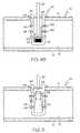
- FIG. 4is a cross-sectional view of an intramedullary infusion device including a compressible member, in which FIG. 4A shows the device before the compressible member has been compressed and FIG. 4B shows the device after the compressible member has been compressed and drug is being delivered.
- FIG. 5is a cross-sectional view of an embodiment of the intramedullary infusion device including a compressible member in which the delivered drug has compressed the compressible member to allow drug elution.
- FIGS. 6A and 6Bare perspective view of an intramedullary infusion device, without outlet structures ( 6 A) and with outlet structures ( 6 B).
- FIG. 1shows an intramedullary access device 10 that has been placed in a bone 12 .
- the bone 12includes a cortical region 14 of relatively dense bone and an underlying region of cancellous bone 16 .
- Cancellous bone 16also known as trabecular or spongy bone, is an osseous bone tissue with low strength and density, including numerous pockets that provide it with a high surface area.
- the intramedullary access device 10includes a tubular conduit 18 with a distal end and a proximal end, and a length sufficient to pass through the cortical region 14 of bone tissue and into the cancellous bone 16 .
- the tubular conduit 18may be provided in a variety of different lengths to accommodate variations in the thickness of the cortical bone.
- the tubular conduit 18may have a length from about 1 millimeter (mm) to about 10 mm, or alternately a length from about 3 mm to about 5 mm.
- the tubular conduit 18includes an outside surface extending from its proximal end to its distal end along a longitudinal axis.
- the tubular conduit 18also includes a tunnel 20 that runs through the center of the tubular conduit 18 along the longitudinal axis.
- the tunnel 20should be wide enough to accommodate a needle 22 or similar device used to administer a pharmaceutically active agent to the cancellous bone 16 .
- the tunnel 20may have a width of about 3 mm to about 10 mm.
- the tubular conduit 18 surrounding the tunnel 20may have an overall diameter of up to 1 cm, with some embodiments having diameters from about 5 mm to about 10 mm.
- the proximal end of the tubular conduit 18includes a flange 24 that circles the proximal end of the conduit 18 .
- the flange 24may provide several advantageous functions, including sealing the gap between the bone 12 and the device 10 to prevent leakage to or from the intramedullary space, infection of the bone or surrounding tissue, over-insertion of the device 10 into the bone 12 , and also provides a protrusion on the surface of the bone 12 that can aid in locating the device 10 by palpitation.
- the flange 24also provides a surface that can be readily modified to facilitate insertion of the intramedullary access device 10 by tools such as device drivers.
- the flange 24may be provided with a slot 26 as shown in FIG. 2 . Alternately, one or more slots 26 may be provided elsewhere on the flange 24 , such as along the circumference of the flange 24 .
- the intramedullary access device 10may be formed using any suitable biocompatible polymer, metal, or ceramic known to those skilled in the art.
- suitable biocompatible materialincluding metals such as cobalt-chromium alloys, titanium alloys, nickel titanium alloys, and/or stainless steel alloys.
- at least a portion of the intramedullary access device 10can be formed of magnetic material to facilitate its detection.
- Polymer materialsmay also be used, including any member of the polyaryletherketone (PAEK) family such as polyetheretherketone (PEEK), carbon-reinforced PEEK, or polyetherketoneketone (PEKK); polysulfone; polyetherimide; polyimide; ultra-high molecular weight polyethylene (UHMWPE); and/or cross-linked UHMWPE.
- PAEKpolyaryletherketone
- PEEKpolyetheretherketone
- PEEKcarbon-reinforced PEEK
- PEKKpolyetherketoneketone
- polysulfonepolyetherimide
- polyimidepolyimide
- UHMWPEultra-high molecular weight polyethylene
- UHMWPEultra-high molecular weight polyethylene
- the intramedullary access device 10generally includes a penetrable diaphragm 28 positioned within the tunnel 20 of the tubular conduit 18 .
- the diaphragm 28seals the tunnel of the intramedullary access device 10 to prevent leakage to and from the intramedullary region, and/or to prevent infection.
- the diaphragmmay be retained within the tubular conduit 18 by, for example, using adhesives or threading that fits within the tunnel 20 .
- the diaphragm 28should be penetrable to allow a needle or similar device to penetrate through the diaphragm so that the intramedullary region may be accessed to deliver pharmacologically active agent or obtain samples (e.g., blood samples).
- the penetrable diaphragm 28may be formed from, for example, an elastomer selected from the group consisting of polyurethane, styrene butadiene styrene, or silicone. Alternately, a guide port and a flapper valve together with a flapper strike plate may be used in place of a penetrable diaphragm 28 within the tunnel 20 .
- the outside surface of the tubular conduit 18may be smooth, or it may include texturing 30 and/or threading 32 . Including texturing and/or threading can provide better integration, reduce shear stress, and/or improve fixation to the bone. In some embodiments, threading and texturing may be combined, such that either the threads are formed from texturing or they include additional texturing on the surface of the threads.
- the screw threads includedare of a conventional design. Accordingly, they consist of a generally helical thread 32 that winds along the length of the outside surface of the tubular conduit 18 .
- a single continuous threadcan be used, or plural parallel threads or interrupted thread segments may be employed as is known in the art. While threading may simply be provided along the length of the tubular conduit 18 , threading that allows the intramedullary access device 10 to function as a self-tapping screw may also be used. Self-tapping threading may narrow to a point and including notching at the distal end of the tubular conduit 18 , and provide the advantage of making their own threads as the threaded tubular conduit 18 is screwed into a bore drilled into bone 12 .
- Various types of screw threading, and threading including surface texturingis described in U.S. Pat. No. 5,868,747, which is incorporated herein by reference.
- the intramedullary access device 10can also include texturing 30 on the outer surface of the tubular conduit 18 to enhance the fixation of the device 10 .
- the surfacesmay be roughened such as by chemical etching, bead-blasting, sanding, grinding, serrating, and/or diamond-cutting.
- the surface texturingcan be of small magnitude so that it does not abrade the bone surface, with the texturing extending outward from the surface so that the area of contact with bone is reduced, at least upon initial insertion. After insertion, when the bone has had an opportunity to relax or decompress and conform to the textured surface, a larger surface area contacts bone, making removal more difficult.
- Surface texturing with specific geometriescan also be provided.
- Such surface texturingcan be asymmetric or anisotropic, with angled features that facilitate installation or discourage loosening.
- This type of surface texturingmay be provided by a variety of methods, such as directed sputtering by ion beam bombardment, ion beam bombardment through a pattern defining mask, sputter-etching, or machining.
- the intramedullary access devicecan include a helical thread projecting from the outside surface of the tubular conduit 18 comprising a plurality of micropillars projecting therefrom.
- a plurality of micropillarsmay project from the exterior surface of the shell in a regular, non-helical array.
- the pillarsmay be cylindrical, square, rectangular, or crescent-shaped. Use of micropillars to provide threading is described in U.S. Pat. No. 6,071,310, which is incorporated herein by reference.
- All or a portion of the outer surface of the tubular conduit 18may also be provided with a biocompatible and osteoconductive material such as hydroxyapatite (HA), tricalcium phosphate (TCP), and/or calcium carbonate to promote bone in growth and fixation.
- a biocompatible and osteoconductive materialsuch as hydroxyapatite (HA), tricalcium phosphate (TCP), and/or calcium carbonate to promote bone in growth and fixation.
- osteoinductive coatingssuch as proteins from transforming growth factor (TGF) beta superfamily, or bone-morphogenic proteins, such as BMP2 or BMP7, may be used.
- TGFtransforming growth factor
- BMP2 or BMP7bone-morphogenic proteins
- Other suitable featuresmay include spikes for initial fixation; ridges or keels to prevent migration in the lateral and anterior direction, for example; serrations or diamond cut surfaces; fins; posts; and/or other surface textures.
- the intramedullary access device 10can be fitted with various diagnostic sensors 34 in order to detect one or more physical parameters.
- the detected parametersmay include, for example, pressure, linear displacement, angular displacement, temperature, pH, or glucose metabolic chemistries.
- a system for analyzing physical parameters using sensors associated with an intramedullary access device 10is shown in FIG. 3 .
- the intramedullary access devicemay include one or more sensors 34 coupled to a biotelemetry transmitter 36 . Multiple sensors 34 may be used to measure multiple physical parameters simultaneously.
- the sensors 34can include microscopic sensing element or elements fabricated using semiconductor or MEMS (microelectromechanical systems) fabrication technology.
- the intramedullary access device 10may further include a transmitter 36 which may be wired or wirelessly coupled to the sensors 34 . It is understood that additional components such as power components, memory components, a CPU, or additional transmitters may be incorporated in the device 10 as needed.
- the systemcan also include a power supply 38 associated with the transmitter 36 .
- the power supply 38 and the transmitter 36are shown as being incorporated into the intramedullary access device 10 , but they can also be provided external to the device 10 .
- Several methodsare available to power the sensor 34 remotely.
- the sensor 34can be powered remotely using magnetic or RF induction.
- the analog data from the sensor 34will be converted to frequency and will be transmitted using a low-power RF transmitter.
- a self-power generating systemincluding substituting stacks of piezoelectric material can be included. See for example U.S. Pat. No. 7,097,662, which is incorporated herein by reference.
- the systemcan further include a receiver 40 in communication with the transmitter 36 .
- the transmitter 36 and the receiver 40may communicate data about the physical parameters detected by the one or more sensors 34 through telemetry or percutaneous wires (e.g., RF signals).
- the receiver 40may be connected to a computer 42 for processing the received data about the physical parameters detected by the sensors 34 . Further information regarding sensors suitable for inclusion in implanted orthopedic devices can be found in U.S. patent application Ser. Nos. 11/118,170 and 11/147,750, which are incorporated herein by reference.
- the intramedullary infusion device 44includes a tubular conduit 18 with a distal end and a proximal end, and a flange 24 circling the outside of the proximal end of the conduit, as well as a penetrable diaphragm 28 positioned within the tubular conduit 18 .
- the tubular conduitis closed at the distal end.
- the tubular conduit 18has a length sufficient to extend through the cortical region 14 of the bone 12 and extend into the cancellous 16 region.
- the intramedullary infusion device 44may have a length longer than that typically used for the intramedullary access device 10 described earlier herein.
- the intramedullary infusion device 44can include one or more sensors 34 .
- One or more outlet openings 46may be provided along the sides of the tubular conduit 18 .
- the outlet openings 46are in communication with the interior of the tubular conduit 18 , and can accommodate the flow of fluid from the intramedullary access device 10 to the cancellous bone 16 .
- the outlet openings 46can have various sizes depending on the desired flow rate.
- the outlet openings 46can have a diameter from about 3 ⁇ m to 10 ⁇ m.
- a plurality of outlet openings 46are provided to minimize resistance to the effusion of liquid from the intramedullary effusion device 44 and to help diffuse the release of such liquid.
- outlet openings 46are used for delivering fluid to the cancellous bone 16 , the outlet openings 46 are not provided near the proximal end of the tubular conduit 18 , but rather are positioned towards the distal end where they can be expected to contact the cancellous bone 16 upon insertion.
- the outlet openings 46may simply be channels that run through the sides of the tubular conduit 18 , as shown in FIG. 6A . However, the outlet openings 46 can also be positioned so that they also run through an outlet structure 48 provided on the surface of the tubular conduit, as shown in FIG. 6B .
- the outlet structures 48may have a variety of shapes, such as pillars (cylindrical, square, rectangular, etc.) or fins.
- the outlet structures 48typically have a length from about 3 ⁇ m to about 15 ⁇ m.
- the outlet openings 46extend through both the tubular conduit 18 and the outlet structures 48 and can facilitate fluid flow by extending beyond fibrous capsule formation that may occur around the intramedullary infusion device 44 after it has been placed in the bone that might otherwise block fluid flow.
- the intramedullary infusion device 44also includes a collapsible member 50 positioned over the outlet openings 46 when in its non-collapsed state.
- the collapsible member 50functions to prevent flow into our out of the intramedullary infusion device 44 unless it is subject to pressure which moves it past the outlet openings 46 . This is illustrated in FIGS. 4 a , 4 b , and 5 .
- FIGS. 4 a and 4 bshow an embodiment of the intramedullary infusion device 44 in which the collapsible member 50 is moveable diaphragm 52 that fits within the tubular conduit 18 and is supported by a spring 54 .
- the diaphragm 52 and the spring 54may be replaced by other collapsible members 50 such as a compressible elastomer.
- FIG. 4 athe intramedullary infusion device 44 is shown in its normal configuration, in which liquid cannot flow into or from the device because the outlet openings 46 are blocked by the collapsible member 50 .
- FIG. 4 bwhen pressure is applied (e.g, by the needle 22 ) to compress the compressible member 50 , the compressible member 50 moves towards the distal end of the tubular conduit, exposing one or more of the outlet openings 46 .
- liquide.g., liquid carrying a pharmacologically active agent 56
- fluidcan flow from the intramedullary infusion device 44 to the surrounding cancellous region 16 of the bone 12 .
- fluidmay be drawn into the intramedullary infusion device 44 for collection.
- FIG. 5shows another embodiment of the intramedullary infusion device 44 .
- the collapsible member 50 in this embodimentis capable of contracting inwards as well as compressing downwards in response to the application of pressure. Accordingly, as shown in FIG. 5 , the application of pressure, as indicated by the large arrow, results in the collapsible member 50 contracting inwards, as indicated by the thin arrows, allowing liquid (e.g., liquid carrying a pharmacologically active agent 56 ) to flow past the collapsible member 50 and outwards into the surrounding cancellous region 16 of the bone.
- liquide.g., liquid carrying a pharmacologically active agent 56
- the intramedullary access device 10can be inserted into the bone by various methods known to those skilled in the art.
- a drillmay first be used to bore a proper sized hole for fitting the device 10 into the bone 12 .
- An incisionis made in the skin of the patient, preferably after cleaning and administration of an anesthetic, and a hole is then drilled into the bone 12 .
- the incisionmay be made at a position slightly offset from the location where the hole will be drilled in order to prevent the formation of scar tissue and/or inhibit subsequent infection at the infusion site where the device 10 is placed.
- the drillshould have a drill bit with a spiral cutting edge suitable to cut and remove cortical and cancellous bone.
- the boremay be smooth or may be threaded, depending on the nature of the device 10 being used.
- the drillingmay be done at low speed with good irrigation to minimize trauma to the bone.
- the intramedullary access device 10may be placed in any location suitable for intraosseous infusion, such as the middle or the end portions of a bone. Specific sites suitable for intraosseous infusion include the proximal tibia and/or the sternum.
- the device 10can then be inserted by tapping it into place.
- the device 10is typically inserted with the diaphragm 28 positioned within the device 10 .
- the diaphragm 28can also be placed in the device 10 subsequent to insertion.
- embodiments including texturing 30 on the outer surface of the tubular conduit 18can be readily inserted by tapping, and that the texturing 30 will help retain the inserted device in place.
- Biocompatible adhesivescan also be used to help retain the intramedullary access device 10 .
- the device by tappingit may be inserted by screwing it in if the device includes threading.
- the device 10may be screwed in by engaging slots 26 within the flange 24 and then rotating a tool to screw the device 10 into the bone 20 .
- the tool or device drivermay be in the shape of a standard screw driver or standard orthopedic instrument handle with keys to accommodate the flange much like a socket wrench engages a nut.
- the skincan be sutured closed for subsequent percutaneous access by a needle 22 .
- the skinis allowed to heal prior to use of the device; however, the device 10 may be used immediately if necessary.
- itmay be desirable to position a thin sheet of biocompatible microporous polymeric material covering the region where the skin will be replaced after insertion of the device. Use of such polymeric material can help anchor the skin and avoid formation of deadspace that can lead to infection or other problems.
- the intramedullary access device 10remains in place until needed. However, should the device 10 become plugged, it can be removed and the area cleaned. For example, cutters (e.g., flexshaft driven) can be introduced to open the blockage and restore access to the blood vessels within the cancellous bone tissue, after which the device 10 can be re-inserted. Furthermore, should the penetrable diaphragm 28 become damaged, it can be replaced without removing the access device 10 and damaging the surrounding bone tissue. Replacement of the penetrable diaphragm 28 may, for example, be necessary if the diaphragm 28 has been damaged as a result of repeated use of the device 10 .
- cutterse.g., flexshaft driven
- the intramedullary access device 10must be placed within the bone 12 before use.
- the intramedullary access device 10may be implanted at any convenient time by skilled medical personnel.
- Other advantages to the use of an intramedullary access device 10include increased speed of use and decreased pain to the subject during use.
- the intramedullary access device 10To use the intramedullary access device 10 , it is first located by palpitation, markings, or knowledge regarding its typical placement. In the case of intramedullary access devices 10 that include a magnetic material, it may be detecting by locating the magnetic field or response to a magnetic field engendered by the device 10 . Once located, a needle 22 is then properly oriented above the intramedullary access device 10 and then driven through the skin and soft tissue through the penetrable diaphragm 28 within the intramedullary access device 10 , and into the cancellous bone 16 . Preferably, the skin is prepared (e.g., cleaned) before the infusion needle 22 is inserted into the access device 10 .
- the skinis prepared (e.g., cleaned) before the infusion needle 22 is inserted into the access device 10 .
- liquidmay be delivered from the needle 22 .
- the liquidis preferably delivered at a rate of about 100 mL/minute, though depending on the nature of the intraosseous space, lower delivery rates such as about 50 mL/minute may be used.
- a variety of fluids and liquids carrying pharmacologically active agents 56can be administered.
- fluidssuch as hypertonic saline, blood, and lactated Ringer's solution may be administered.
- Pharmacologically active agents that may be administeredinclude, for example, aminophylline, amiodarone, atropine, domapine, epinephrine, etomidate, fentanyl, levophed, lidocaine, promethezine, recuronium, succinylchonline, thiamine, vasopressin, chemotherapeutic agents, or any other drug that is typically administered intravenously.
- a local anestheticsuch as lidocaine to minimize visceral pain from pressure within the bone.
- the intramedullary access device 10can also be used to provide a convenient access point for sampling blood chemistries, partial pressure of arterial carbon dioxide, pH, and hemogloblin counts, for example.
- embodiments of the intramedullary access device 10can also include sensors 34 to monitor various parameters of medical interest.
- the intramedullary access device 10may be used as often as needed to provide access for intraosseous infusion.
- the intramedullary access device 10may be left in place in the bone for as long as there is a significant chance that it will be needed.
- the intramedullary access device 10could be implanted before the soldiers enter combat and then removed at the end of their service.
- the intramedullary access device 10is particularly valuable for individuals who are placed in high risk situations.
- Soldierswould also particularly benefit from ready intraosseous access, because acute hemorrhage is a major cause of battlefield death, and treatment must often be carried out hastily under high stress conditions upon soldiers in a hypotensive state with collapsed peripheral veins.
Landscapes
- Health & Medical Sciences (AREA)
- Heart & Thoracic Surgery (AREA)
- Life Sciences & Earth Sciences (AREA)
- General Health & Medical Sciences (AREA)
- Veterinary Medicine (AREA)
- Engineering & Computer Science (AREA)
- Biomedical Technology (AREA)
- Public Health (AREA)
- Animal Behavior & Ethology (AREA)
- Anesthesiology (AREA)
- Hematology (AREA)
- Pulmonology (AREA)
- Surgery (AREA)
- Orthopedic Medicine & Surgery (AREA)
- Pathology (AREA)
- Nuclear Medicine, Radiotherapy & Molecular Imaging (AREA)
- Medical Informatics (AREA)
- Molecular Biology (AREA)
- Surgical Instruments (AREA)
Abstract
Description
Claims (13)
Priority Applications (1)
| Application Number | Priority Date | Filing Date | Title |
|---|---|---|---|
| US12/119,867US7833204B2 (en) | 2007-05-14 | 2008-05-13 | Intramedullary access or infusion devices |
Applications Claiming Priority (2)
| Application Number | Priority Date | Filing Date | Title |
|---|---|---|---|
| US91778707P | 2007-05-14 | 2007-05-14 | |
| US12/119,867US7833204B2 (en) | 2007-05-14 | 2008-05-13 | Intramedullary access or infusion devices |
Publications (2)
| Publication Number | Publication Date |
|---|---|
| US20080287910A1 US20080287910A1 (en) | 2008-11-20 |
| US7833204B2true US7833204B2 (en) | 2010-11-16 |
Family
ID=40028273
Family Applications (1)
| Application Number | Title | Priority Date | Filing Date |
|---|---|---|---|
| US12/119,867ActiveUS7833204B2 (en) | 2007-05-14 | 2008-05-13 | Intramedullary access or infusion devices |
Country Status (1)
| Country | Link |
|---|---|
| US (1) | US7833204B2 (en) |
Cited By (26)
| Publication number | Priority date | Publication date | Assignee | Title |
|---|---|---|---|---|
| US20080275395A1 (en)* | 2006-12-22 | 2008-11-06 | Innerspace Medical, Inc. | MRI-Compatible Temperature-Sensing Catheter |
| US20090216196A1 (en)* | 2008-02-27 | 2009-08-27 | Entellus Medical, Inc. | Apparatus and method for accessing a sinus cavity |
| US20120116316A1 (en)* | 2010-11-08 | 2012-05-10 | Schutz Daniel | Method for implanting an access port |
| CN104703652A (en)* | 2012-10-02 | 2015-06-10 | 瑞尼斯豪公司 | Neurosurgical device and method |
| US9649427B2 (en) | 2011-12-28 | 2017-05-16 | Xerem Medical Ltd. | System and method for blood filtering and/or treatment |
| US9770425B2 (en) | 2014-10-09 | 2017-09-26 | Aperture Medical Technology Llc | Implantable bone marrow access apparatus |
| US10016564B2 (en) | 2015-02-24 | 2018-07-10 | 410 Medical, Inc. | Apparatus and kits for fluid infusion |
| US10322227B2 (en) | 2013-03-15 | 2019-06-18 | 410 Medical, Inc. | Apparatus, kits and related methods for fluid infusion |
| US10448933B2 (en) | 2016-10-05 | 2019-10-22 | Aperture Medical Technology Llc | Bone marrow access system |
| US10507316B2 (en) | 2010-02-12 | 2019-12-17 | Renishaw (Ireland) Limited | Implantable fluid router |
| US10751520B2 (en) | 2006-11-23 | 2020-08-25 | Renishaw (Ireland) Limited | Neurological apparatus comprising a percutaneous access device |
| US11517349B2 (en) | 2019-09-27 | 2022-12-06 | Bard Access Systems, Inc. | Autovance feature of an intraosseous device |
| US11534145B2 (en) | 2018-10-12 | 2022-12-27 | Aperture Medical Technology Llc | Bone marrow access apparatus and methods for locating same |
| US11633214B2 (en) | 2019-09-27 | 2023-04-25 | Bard Access Systems, Inc. | Various operating mechanisms for intraosseous access medical devices and methods thereof |
| US11744936B2 (en) | 2021-03-08 | 2023-09-05 | 410 Medical, Inc. | Systems, apparatus, and methods for fluid infusion |
| US11759235B2 (en) | 2019-09-27 | 2023-09-19 | Bard Access Systems, Inc. | Constant-torque intraosseous access devices and methods thereof |
| US11883071B2 (en) | 2016-10-27 | 2024-01-30 | C. R. Bard, Inc. | Intraosseous access device |
| US11896264B2 (en) | 2020-04-21 | 2024-02-13 | Bard Access Systems, Inc. | Reusable push-activated intraosseous access device |
| US11925361B2 (en) | 2021-02-08 | 2024-03-12 | Bard Access Systems, Inc. | Intraosseous modular power |
| US11998237B2 (en) | 2020-06-03 | 2024-06-04 | Bard Access Systems, Inc. | Intraosseous device including a sensing obturator |
| US12082843B2 (en) | 2019-09-27 | 2024-09-10 | Bard Access Systems, Inc. | Step needle for intraosseous access device |
| US12167869B2 (en) | 2020-02-28 | 2024-12-17 | Bard Access Systems, Inc. | Flexible intraosseous obturator |
| WO2025024389A1 (en)* | 2023-07-21 | 2025-01-30 | Whisper Medical, Inc. | Cranial access port system |
| US12226123B2 (en) | 2020-07-17 | 2025-02-18 | Bard Access Systems, Inc. | Safety mechanism |
| US12274469B2 (en) | 2020-08-25 | 2025-04-15 | Bard Access Systems, Inc. | Angled intraosseous access system |
| US12402911B2 (en) | 2020-09-09 | 2025-09-02 | Bard Access Systems, Inc. | Aspiration apparatus for intraosseous access system |
Families Citing this family (10)
| Publication number | Priority date | Publication date | Assignee | Title |
|---|---|---|---|---|
| US20070265584A1 (en)* | 2006-02-15 | 2007-11-15 | Hickman Robert O | Venous prosthesis and vascular graft with access port |
| US8771354B2 (en) | 2011-10-26 | 2014-07-08 | George J. Picha | Hard-tissue implant |
| US20130197468A1 (en)* | 2012-01-26 | 2013-08-01 | Carnegie Mellon University | Device for Intramyocardial Delivery |
| WO2014134438A1 (en)* | 2013-03-01 | 2014-09-04 | The United States Of America, As Represented By The Secretary, Department Of Health & Human Services | Direct pressure-mediated intra-bone delivery system for cellular therapeutics |
| US20150025500A1 (en)* | 2013-03-15 | 2015-01-22 | North Carolina State University | Apparatus and method for intraosseous fluid infusion |
| JP6835731B2 (en)* | 2014-11-13 | 2021-02-24 | パヴメド・インコーポレイテッドPAVMed Inc. | Intraosseous infusion port and usage |
| EP3592283B1 (en) | 2017-03-10 | 2024-05-08 | Alps Holding Llc | Hard-tissue implant comprising a bulk implant, a face, pillars, slots, and at least one support member |
| US11324606B2 (en) | 2017-03-10 | 2022-05-10 | Gary A. Zwick | Spinal interbody cage comprising a bulk interbody cage, a top face, a bottom face, pillars, and slots |
| US11278427B2 (en) | 2018-04-10 | 2022-03-22 | Gary A. Zick, Trustee Of The Everest Trust Uta April 20, 2017 | Spinal interbody cage comprising top and bottom faces with mesh structures, pillars and slots |
| JP7335428B2 (en) | 2019-09-11 | 2023-08-29 | アルプス ホールディング エルエルシー | An implant comprising a first set and a second set of pillars for attaching a tendon or ligament to hard tissue |
Citations (37)
| Publication number | Priority date | Publication date | Assignee | Title |
|---|---|---|---|---|
| US3136316A (en) | 1962-01-19 | 1964-06-09 | Abbott Lab | Catheter |
| US3626950A (en) | 1970-06-19 | 1971-12-14 | Heyer Schulte Corp | Catheter with augmented drainage means |
| USRE27310E (en) | 1970-09-23 | 1972-03-21 | Cerebro-ventricular catheter | |
| US4579555A (en) | 1983-12-05 | 1986-04-01 | Sil-Fab Corporation | Surgical gravity drain having aligned longitudinally extending capillary drainage channels |
| DE3536178A1 (en) | 1985-10-10 | 1987-04-16 | Fresenius Ag | Injection site for hollow bones |
| US4772261A (en) | 1987-01-29 | 1988-09-20 | Board Of Regents, The University Of Texas System | Intramedullary catheter |
| US4850953A (en)* | 1987-07-27 | 1989-07-25 | Habley Medical Technology Corporation | Gastrostomy valve |
| US4969870A (en) | 1989-06-07 | 1990-11-13 | The Regents Of The University Of California | Method and apparatus for intraosseous infusions |
| US5122114A (en) | 1991-02-01 | 1992-06-16 | Board Of Regents, University Of Texas System | Method of using intramedullary catheter |
| US5163924A (en) | 1986-08-26 | 1992-11-17 | Michael Beverly | Implantable bone drain |
| US5207709A (en) | 1991-11-13 | 1993-05-04 | Picha George J | Implant with textured surface |
| US5236453A (en) | 1990-03-09 | 1993-08-17 | Picha George J | Mammary implant and method for reducing capsule contracture |
| US5312364A (en) | 1993-08-06 | 1994-05-17 | Pyng | Intraosseous infusion device |
| US5332398A (en) | 1992-02-01 | 1994-07-26 | Board Of Regents, The University Of Texas System | Intramedullary catheter |
| US5368046A (en) | 1992-09-09 | 1994-11-29 | Symbiosis Corporation | Bone marrow needle assembly |
| US5372583A (en) | 1992-11-25 | 1994-12-13 | Cardiopulmonary Specialities, Inc. | Bone marrow infuser and method of use |
| US5591188A (en) | 1994-04-12 | 1997-01-07 | Wais-Med Lmt, A Subsidiary Company Of Teic Technion Enterpreneurial Incubator Ltd. | Surgical instrument for impact insertion of an intraosseous trocar-needle |
| US5817052A (en) | 1995-12-26 | 1998-10-06 | Pyng Medical Corp. | Apparatus for intraosseous infusion or aspiration |
| US5868711A (en) | 1991-04-29 | 1999-02-09 | Board Of Regents, The University Of Texas System | Implantable intraosseous device for rapid vascular access |
| US5868747A (en) | 1994-12-02 | 1999-02-09 | Johnson & Johnson Professional, Inc. | Directional bone fixation device |
| US5990382A (en) | 1990-08-29 | 1999-11-23 | Biomedical Enterprises, Inc. | Method and implant for surgical manipulation of bone |
| US6030389A (en) | 1997-08-04 | 2000-02-29 | Spinal Concepts, Inc. | System and method for stabilizing the human spine with a bone plate |
| US6071310A (en)* | 1997-05-20 | 2000-06-06 | George J. Picha | Spinal implant |
| US6106558A (en) | 1997-09-15 | 2000-08-22 | Applied Medical Research, Inc. | Neuro decompression device |
| US6106495A (en) | 1998-05-20 | 2000-08-22 | Howmedica Inc. | Methods and apparatus for delivering antibiotic powders into the femoral canal for the reduction of orthopaedic sepsis during total hip arthroplasty |
| US6387098B1 (en) | 1999-10-21 | 2002-05-14 | Peter Alexander Cole | Intramedullary catheter nail apparatus and method |
| US6458117B1 (en) | 2000-01-19 | 2002-10-01 | Kevin Daniel Pollins, Sr. | Intraosseous infusion assembly and method for intraosseous infusion |
| US20020143317A1 (en)* | 2001-03-30 | 2002-10-03 | Glossop Neil David | Device and method for registering a position sensor in an anatomical body |
| US20030225411A1 (en) | 2002-05-31 | 2003-12-04 | Vidacare Corporation | Apparatus and method to access bone marrow |
| US6719738B2 (en) | 1998-11-17 | 2004-04-13 | Henri Mehier | Device for directly delivering an active substance within a cell tissue, means for implanting said device and appliances for injecting active substance into said device |
| US20050131345A1 (en) | 2002-05-31 | 2005-06-16 | Larry Miller | Apparatus and method for accessing the bone marrow of the sternum |
| US20060015066A1 (en) | 2004-05-17 | 2006-01-19 | Turieo Melanie J | Intraosseous infusion device |
| US20060052782A1 (en) | 2004-06-07 | 2006-03-09 | Chad Morgan | Orthopaedic implant with sensors |
| US20060149362A1 (en) | 2004-12-30 | 2006-07-06 | Pedrozo Hugo A | Orthopaedic implant for vascularization of the femoral head |
| US7097662B2 (en) | 2004-08-25 | 2006-08-29 | Ut-Battelle, Llc | In-vivo orthopedic implant diagnostic device for sensing load, wear, and infection |
| US20060247773A1 (en) | 2005-04-29 | 2006-11-02 | Sdgi Holdings, Inc. | Instrumented implant for diagnostics |
| US7608062B2 (en)* | 2003-07-15 | 2009-10-27 | Spinal Generations, Llc | Method and device for delivering medicine to bone |
- 2008
- 2008-05-13USUS12/119,867patent/US7833204B2/enactiveActive
Patent Citations (42)
| Publication number | Priority date | Publication date | Assignee | Title |
|---|---|---|---|---|
| US3136316A (en) | 1962-01-19 | 1964-06-09 | Abbott Lab | Catheter |
| US3626950A (en) | 1970-06-19 | 1971-12-14 | Heyer Schulte Corp | Catheter with augmented drainage means |
| USRE27310E (en) | 1970-09-23 | 1972-03-21 | Cerebro-ventricular catheter | |
| US4579555A (en) | 1983-12-05 | 1986-04-01 | Sil-Fab Corporation | Surgical gravity drain having aligned longitudinally extending capillary drainage channels |
| DE3536178A1 (en) | 1985-10-10 | 1987-04-16 | Fresenius Ag | Injection site for hollow bones |
| US5163924A (en) | 1986-08-26 | 1992-11-17 | Michael Beverly | Implantable bone drain |
| US4772261A (en) | 1987-01-29 | 1988-09-20 | Board Of Regents, The University Of Texas System | Intramedullary catheter |
| US4850953A (en)* | 1987-07-27 | 1989-07-25 | Habley Medical Technology Corporation | Gastrostomy valve |
| US4969870A (en) | 1989-06-07 | 1990-11-13 | The Regents Of The University Of California | Method and apparatus for intraosseous infusions |
| US5236453A (en) | 1990-03-09 | 1993-08-17 | Picha George J | Mammary implant and method for reducing capsule contracture |
| US5990382A (en) | 1990-08-29 | 1999-11-23 | Biomedical Enterprises, Inc. | Method and implant for surgical manipulation of bone |
| US5122114A (en) | 1991-02-01 | 1992-06-16 | Board Of Regents, University Of Texas System | Method of using intramedullary catheter |
| US5868711A (en) | 1991-04-29 | 1999-02-09 | Board Of Regents, The University Of Texas System | Implantable intraosseous device for rapid vascular access |
| US5960797A (en) | 1991-04-29 | 1999-10-05 | Board Of Regents, The University Of Texas System | Implantable intraosseous device for rapid vascular access |
| US5207709A (en) | 1991-11-13 | 1993-05-04 | Picha George J | Implant with textured surface |
| US5332398A (en) | 1992-02-01 | 1994-07-26 | Board Of Regents, The University Of Texas System | Intramedullary catheter |
| US6228088B1 (en)* | 1992-02-01 | 2001-05-08 | Board Of Regents, The University Of Texas System | Combination drill bit and intrametullary catheter and method of using same |
| US5368046A (en) | 1992-09-09 | 1994-11-29 | Symbiosis Corporation | Bone marrow needle assembly |
| US5372583A (en) | 1992-11-25 | 1994-12-13 | Cardiopulmonary Specialities, Inc. | Bone marrow infuser and method of use |
| US5312364A (en) | 1993-08-06 | 1994-05-17 | Pyng | Intraosseous infusion device |
| US5591188A (en) | 1994-04-12 | 1997-01-07 | Wais-Med Lmt, A Subsidiary Company Of Teic Technion Enterpreneurial Incubator Ltd. | Surgical instrument for impact insertion of an intraosseous trocar-needle |
| US5868747A (en) | 1994-12-02 | 1999-02-09 | Johnson & Johnson Professional, Inc. | Directional bone fixation device |
| US6018094A (en)* | 1995-02-06 | 2000-01-25 | Biomedical Enterprises, Inc. | Implant and insert assembly for bone and uses thereof |
| US5817052A (en) | 1995-12-26 | 1998-10-06 | Pyng Medical Corp. | Apparatus for intraosseous infusion or aspiration |
| US6071310A (en)* | 1997-05-20 | 2000-06-06 | George J. Picha | Spinal implant |
| US6346122B1 (en)* | 1997-05-20 | 2002-02-12 | George J. Picha | Spinal implant |
| US6030389A (en) | 1997-08-04 | 2000-02-29 | Spinal Concepts, Inc. | System and method for stabilizing the human spine with a bone plate |
| US6106558A (en) | 1997-09-15 | 2000-08-22 | Applied Medical Research, Inc. | Neuro decompression device |
| US6106495A (en) | 1998-05-20 | 2000-08-22 | Howmedica Inc. | Methods and apparatus for delivering antibiotic powders into the femoral canal for the reduction of orthopaedic sepsis during total hip arthroplasty |
| US6719738B2 (en) | 1998-11-17 | 2004-04-13 | Henri Mehier | Device for directly delivering an active substance within a cell tissue, means for implanting said device and appliances for injecting active substance into said device |
| US6387098B1 (en) | 1999-10-21 | 2002-05-14 | Peter Alexander Cole | Intramedullary catheter nail apparatus and method |
| US6458117B1 (en) | 2000-01-19 | 2002-10-01 | Kevin Daniel Pollins, Sr. | Intraosseous infusion assembly and method for intraosseous infusion |
| US20020143317A1 (en)* | 2001-03-30 | 2002-10-03 | Glossop Neil David | Device and method for registering a position sensor in an anatomical body |
| US20030225411A1 (en) | 2002-05-31 | 2003-12-04 | Vidacare Corporation | Apparatus and method to access bone marrow |
| US20050131345A1 (en) | 2002-05-31 | 2005-06-16 | Larry Miller | Apparatus and method for accessing the bone marrow of the sternum |
| US7608062B2 (en)* | 2003-07-15 | 2009-10-27 | Spinal Generations, Llc | Method and device for delivering medicine to bone |
| US20060015066A1 (en) | 2004-05-17 | 2006-01-19 | Turieo Melanie J | Intraosseous infusion device |
| US20060052782A1 (en) | 2004-06-07 | 2006-03-09 | Chad Morgan | Orthopaedic implant with sensors |
| US7097662B2 (en) | 2004-08-25 | 2006-08-29 | Ut-Battelle, Llc | In-vivo orthopedic implant diagnostic device for sensing load, wear, and infection |
| US20060149362A1 (en) | 2004-12-30 | 2006-07-06 | Pedrozo Hugo A | Orthopaedic implant for vascularization of the femoral head |
| US7217283B2 (en) | 2004-12-30 | 2007-05-15 | Depuy Products, Inc. | Orthopaedic implant for vascularization of the femoral head |
| US20060247773A1 (en) | 2005-04-29 | 2006-11-02 | Sdgi Holdings, Inc. | Instrumented implant for diagnostics |
Non-Patent Citations (9)
Cited By (44)
| Publication number | Priority date | Publication date | Assignee | Title |
|---|---|---|---|---|
| US11717663B2 (en) | 2006-11-23 | 2023-08-08 | Renishaw (Ireland) Limited | Neurological apparatus comprising a percutaneous access device |
| US10751520B2 (en) | 2006-11-23 | 2020-08-25 | Renishaw (Ireland) Limited | Neurological apparatus comprising a percutaneous access device |
| US20080275395A1 (en)* | 2006-12-22 | 2008-11-06 | Innerspace Medical, Inc. | MRI-Compatible Temperature-Sensing Catheter |
| US20090216196A1 (en)* | 2008-02-27 | 2009-08-27 | Entellus Medical, Inc. | Apparatus and method for accessing a sinus cavity |
| US8801670B2 (en)* | 2008-02-27 | 2014-08-12 | Entellus Medical, Inc. | Apparatus and method for accessing a sinus cavity |
| US9440049B2 (en) | 2008-02-27 | 2016-09-13 | Entellus Medical, Inc. | Apparatus and method for accessing a sinus cavity |
| US10596362B2 (en) | 2010-02-12 | 2020-03-24 | Renishaw (Ireland) Limited | Percutaneous drug delivery apparatus |
| US10507316B2 (en) | 2010-02-12 | 2019-12-17 | Renishaw (Ireland) Limited | Implantable fluid router |
| US11826536B2 (en) | 2010-02-12 | 2023-11-28 | Renishaw (Ireland) Limited | Percutaneous drug delivery apparatus |
| US20120116316A1 (en)* | 2010-11-08 | 2012-05-10 | Schutz Daniel | Method for implanting an access port |
| US9333331B2 (en)* | 2010-11-08 | 2016-05-10 | Cendres+Metaux Sa | Method for implanting an access port |
| US9649427B2 (en) | 2011-12-28 | 2017-05-16 | Xerem Medical Ltd. | System and method for blood filtering and/or treatment |
| CN104703652A (en)* | 2012-10-02 | 2015-06-10 | 瑞尼斯豪公司 | Neurosurgical device and method |
| US9662484B2 (en) | 2012-10-02 | 2017-05-30 | Renishaw Plc | Neurosurgical device and method |
| US10322227B2 (en) | 2013-03-15 | 2019-06-18 | 410 Medical, Inc. | Apparatus, kits and related methods for fluid infusion |
| US9770425B2 (en) | 2014-10-09 | 2017-09-26 | Aperture Medical Technology Llc | Implantable bone marrow access apparatus |
| US10391257B2 (en) | 2015-02-24 | 2019-08-27 | 410 Medical, Inc. | Apparatus and kits for fluid infusion |
| US11458256B2 (en) | 2015-02-24 | 2022-10-04 | 410 Medical, Inc. | Apparatus and kits for fluid infusion |
| US11957886B2 (en) | 2015-02-24 | 2024-04-16 | 410 Medical, Inc. | Rapid fluid delivery system |
| US10016564B2 (en) | 2015-02-24 | 2018-07-10 | 410 Medical, Inc. | Apparatus and kits for fluid infusion |
| US10517576B2 (en) | 2016-10-05 | 2019-12-31 | Aperture Medical Technology Llc | Bone marrow access apparatus |
| US11103223B2 (en) | 2016-10-05 | 2021-08-31 | Aperture Medical Technology Llc | Bone marrow access apparatus |
| US10448933B2 (en) | 2016-10-05 | 2019-10-22 | Aperture Medical Technology Llc | Bone marrow access system |
| US11849926B2 (en) | 2016-10-05 | 2023-12-26 | Aperture Medical Technology Llc | Bone marrow access apparatus |
| US11883071B2 (en) | 2016-10-27 | 2024-01-30 | C. R. Bard, Inc. | Intraosseous access device |
| US12171415B2 (en) | 2018-10-12 | 2024-12-24 | Aperture Medical Technology Llc | Bone marrow access apparatus and methods for locating same |
| US11534145B2 (en) | 2018-10-12 | 2022-12-27 | Aperture Medical Technology Llc | Bone marrow access apparatus and methods for locating same |
| US11633214B2 (en) | 2019-09-27 | 2023-04-25 | Bard Access Systems, Inc. | Various operating mechanisms for intraosseous access medical devices and methods thereof |
| US12178471B2 (en) | 2019-09-27 | 2024-12-31 | Bard Access Systems, Inc. | Autovance feature of an intraosseous device |
| US12226124B2 (en) | 2019-09-27 | 2025-02-18 | Bard Access Systems, Inc. | Constant-torque intraosseous access devices and methods thereof |
| US11759235B2 (en) | 2019-09-27 | 2023-09-19 | Bard Access Systems, Inc. | Constant-torque intraosseous access devices and methods thereof |
| US12082843B2 (en) | 2019-09-27 | 2024-09-10 | Bard Access Systems, Inc. | Step needle for intraosseous access device |
| US11517349B2 (en) | 2019-09-27 | 2022-12-06 | Bard Access Systems, Inc. | Autovance feature of an intraosseous device |
| US12167869B2 (en) | 2020-02-28 | 2024-12-17 | Bard Access Systems, Inc. | Flexible intraosseous obturator |
| US11896264B2 (en) | 2020-04-21 | 2024-02-13 | Bard Access Systems, Inc. | Reusable push-activated intraosseous access device |
| US12193710B2 (en) | 2020-04-21 | 2025-01-14 | Bard Access Systems, Inc. | Reusable push-activated intraosseous access device |
| US11998237B2 (en) | 2020-06-03 | 2024-06-04 | Bard Access Systems, Inc. | Intraosseous device including a sensing obturator |
| US12226123B2 (en) | 2020-07-17 | 2025-02-18 | Bard Access Systems, Inc. | Safety mechanism |
| US12274469B2 (en) | 2020-08-25 | 2025-04-15 | Bard Access Systems, Inc. | Angled intraosseous access system |
| US12402911B2 (en) | 2020-09-09 | 2025-09-02 | Bard Access Systems, Inc. | Aspiration apparatus for intraosseous access system |
| US11925361B2 (en) | 2021-02-08 | 2024-03-12 | Bard Access Systems, Inc. | Intraosseous modular power |
| US12390229B2 (en) | 2021-02-08 | 2025-08-19 | Bard Access Systems, Inc. | Intraosseous modular power |
| US11744936B2 (en) | 2021-03-08 | 2023-09-05 | 410 Medical, Inc. | Systems, apparatus, and methods for fluid infusion |
| WO2025024389A1 (en)* | 2023-07-21 | 2025-01-30 | Whisper Medical, Inc. | Cranial access port system |
Also Published As
| Publication number | Publication date |
|---|---|
| US20080287910A1 (en) | 2008-11-20 |
Similar Documents
| Publication | Publication Date | Title |
|---|---|---|
| US7833204B2 (en) | Intramedullary access or infusion devices | |
| US6210376B1 (en) | Cannulated delivery pin | |
| US8419683B2 (en) | Intraosseous device and methods for accessing bone marrow in the sternum and other target areas | |
| JP3414733B2 (en) | Improved intramedullary catheter | |
| US8343138B2 (en) | Subdural evacuation port aspiration device | |
| US10188440B2 (en) | Method and device for delivering medicine to bone | |
| US5990382A (en) | Method and implant for surgical manipulation of bone | |
| US5332398A (en) | Intramedullary catheter | |
| CA2698195C (en) | Spinal aspiration apparatus | |
| US20180221570A1 (en) | Pumping apparatuses and methods for fluid infusion | |
| US9226735B2 (en) | Articulating cranial bolt | |
| CN113473926B (en) | Intraosseous access device and method of accessing bone marrow | |
| US20110112436A1 (en) | Distraction pins for fluid aspiration | |
| WO2007149302A2 (en) | Bone harvest system | |
| US20080119759A1 (en) | Method and apparatus for aspirating bone marrow | |
| TW201029692A (en) | Manifolds, systems, and methods for administering reduced pressure to a subcutaneous tissue site | |
| US20150314118A1 (en) | System, apparatus and method for establishing intraosseous vascular access | |
| US20040127905A1 (en) | Bone marrow multi-tap | |
| JPH11502750A (en) | Bone implant port and its use |
Legal Events
| Date | Code | Title | Description |
|---|---|---|---|
| AS | Assignment | Owner name:APPLIED MEDICAL RESEARCH, OHIO Free format text:ASSIGNMENT OF ASSIGNORS INTEREST;ASSIGNOR:PICHA, GEORGE J, M.D.;REEL/FRAME:021320/0883 Effective date:20080702 | |
| STCF | Information on status: patent grant | Free format text:PATENTED CASE | |
| FPAY | Fee payment | Year of fee payment:4 | |
| MAFP | Maintenance fee payment | Free format text:PAYMENT OF MAINTENANCE FEE, 8TH YR, SMALL ENTITY (ORIGINAL EVENT CODE: M2552) Year of fee payment:8 | |
| AS | Assignment | Owner name:GARY A. ZWICK, TRUSTEE OF THE EVEREST TRUST UTA AP Free format text:ASSIGNMENT OF ASSIGNORS INTEREST;ASSIGNOR:APPLIED MEDICAL RESEARCH, INC.;REEL/FRAME:047123/0419 Effective date:20180911 | |
| MAFP | Maintenance fee payment | Free format text:PAYMENT OF MAINTENANCE FEE, 12TH YR, SMALL ENTITY (ORIGINAL EVENT CODE: M2553); ENTITY STATUS OF PATENT OWNER: SMALL ENTITY Year of fee payment:12 | |
| AS | Assignment | Owner name:EVEREST HOLDING COMPANY LLC, OHIO Free format text:ASSIGNMENT OF ASSIGNORS INTEREST;ASSIGNOR:GARY A. ZWICK, TRUSTEE OF THE EVEREST TRUST UTA APRIL 20, 2017;REEL/FRAME:062100/0645 Effective date:20221201 |