US7833133B2 - End of travel stop for an exercise device - Google Patents
End of travel stop for an exercise deviceDownload PDFInfo
- Publication number
- US7833133B2 US7833133B2US11/646,882US64688206AUS7833133B2US 7833133 B2US7833133 B2US 7833133B2US 64688206 AUS64688206 AUS 64688206AUS 7833133 B2US7833133 B2US 7833133B2
- Authority
- US
- United States
- Prior art keywords
- travel
- exercise apparatus
- foot
- percent
- foot member
- Prior art date
- Legal status (The legal status is an assumption and is not a legal conclusion. Google has not performed a legal analysis and makes no representation as to the accuracy of the status listed.)
- Active, expires
Links
Images


Classifications
- A—HUMAN NECESSITIES
- A63—SPORTS; GAMES; AMUSEMENTS
- A63B—APPARATUS FOR PHYSICAL TRAINING, GYMNASTICS, SWIMMING, CLIMBING, OR FENCING; BALL GAMES; TRAINING EQUIPMENT
- A63B22/00—Exercising apparatus specially adapted for conditioning the cardio-vascular system, for training agility or co-ordination of movements
- A63B22/06—Exercising apparatus specially adapted for conditioning the cardio-vascular system, for training agility or co-ordination of movements with support elements performing a rotating cycling movement, i.e. a closed path movement
- A63B22/0664—Exercising apparatus specially adapted for conditioning the cardio-vascular system, for training agility or co-ordination of movements with support elements performing a rotating cycling movement, i.e. a closed path movement performing an elliptic movement
- A—HUMAN NECESSITIES
- A63—SPORTS; GAMES; AMUSEMENTS
- A63B—APPARATUS FOR PHYSICAL TRAINING, GYMNASTICS, SWIMMING, CLIMBING, OR FENCING; BALL GAMES; TRAINING EQUIPMENT
- A63B22/00—Exercising apparatus specially adapted for conditioning the cardio-vascular system, for training agility or co-ordination of movements
- A63B22/0002—Exercising apparatus specially adapted for conditioning the cardio-vascular system, for training agility or co-ordination of movements involving an exercising of arms
- A63B22/001—Exercising apparatus specially adapted for conditioning the cardio-vascular system, for training agility or co-ordination of movements involving an exercising of arms by simultaneously exercising arms and legs, e.g. diagonally in anti-phase
- A—HUMAN NECESSITIES
- A63—SPORTS; GAMES; AMUSEMENTS
- A63B—APPARATUS FOR PHYSICAL TRAINING, GYMNASTICS, SWIMMING, CLIMBING, OR FENCING; BALL GAMES; TRAINING EQUIPMENT
- A63B22/00—Exercising apparatus specially adapted for conditioning the cardio-vascular system, for training agility or co-ordination of movements
- A63B22/0015—Exercising apparatus specially adapted for conditioning the cardio-vascular system, for training agility or co-ordination of movements with an adjustable movement path of the support elements
- A63B22/0017—Exercising apparatus specially adapted for conditioning the cardio-vascular system, for training agility or co-ordination of movements with an adjustable movement path of the support elements the adjustment being controlled by movement of the user
- A—HUMAN NECESSITIES
- A63—SPORTS; GAMES; AMUSEMENTS
- A63B—APPARATUS FOR PHYSICAL TRAINING, GYMNASTICS, SWIMMING, CLIMBING, OR FENCING; BALL GAMES; TRAINING EQUIPMENT
- A63B23/00—Exercising apparatus specially adapted for particular parts of the body
- A63B23/035—Exercising apparatus specially adapted for particular parts of the body for limbs, i.e. upper or lower limbs, e.g. simultaneously
- A63B23/04—Exercising apparatus specially adapted for particular parts of the body for limbs, i.e. upper or lower limbs, e.g. simultaneously for lower limbs
- A63B23/0405—Exercising apparatus specially adapted for particular parts of the body for limbs, i.e. upper or lower limbs, e.g. simultaneously for lower limbs involving a bending of the knee and hip joints simultaneously
- A63B23/0429—Exercising apparatus specially adapted for particular parts of the body for limbs, i.e. upper or lower limbs, e.g. simultaneously for lower limbs involving a bending of the knee and hip joints simultaneously with guided foot supports moving parallel to the body-symmetrical-plane by being cantilevered about a horizontal axis
- A—HUMAN NECESSITIES
- A63—SPORTS; GAMES; AMUSEMENTS
- A63B—APPARATUS FOR PHYSICAL TRAINING, GYMNASTICS, SWIMMING, CLIMBING, OR FENCING; BALL GAMES; TRAINING EQUIPMENT
- A63B22/00—Exercising apparatus specially adapted for conditioning the cardio-vascular system, for training agility or co-ordination of movements
- A63B22/06—Exercising apparatus specially adapted for conditioning the cardio-vascular system, for training agility or co-ordination of movements with support elements performing a rotating cycling movement, i.e. a closed path movement
- A63B22/0664—Exercising apparatus specially adapted for conditioning the cardio-vascular system, for training agility or co-ordination of movements with support elements performing a rotating cycling movement, i.e. a closed path movement performing an elliptic movement
- A63B2022/0676—Exercising apparatus specially adapted for conditioning the cardio-vascular system, for training agility or co-ordination of movements with support elements performing a rotating cycling movement, i.e. a closed path movement performing an elliptic movement with crank and handles being on the same side of the exercising apparatus with respect to the frontal body-plane of the user, e.g. crank and handles are in front of the user
- A63B2022/0682—Exercising apparatus specially adapted for conditioning the cardio-vascular system, for training agility or co-ordination of movements with support elements performing a rotating cycling movement, i.e. a closed path movement performing an elliptic movement with crank and handles being on the same side of the exercising apparatus with respect to the frontal body-plane of the user, e.g. crank and handles are in front of the user with support elements being cantilevered, i.e. the elements being supported only on one side without bearing on tracks on the floor below the user
- A—HUMAN NECESSITIES
- A63—SPORTS; GAMES; AMUSEMENTS
- A63B—APPARATUS FOR PHYSICAL TRAINING, GYMNASTICS, SWIMMING, CLIMBING, OR FENCING; BALL GAMES; TRAINING EQUIPMENT
- A63B71/00—Games or sports accessories not covered in groups A63B1/00 - A63B69/00
- A63B71/0054—Features for injury prevention on an apparatus, e.g. shock absorbers
- A63B2071/0063—Shock absorbers
- A—HUMAN NECESSITIES
- A63—SPORTS; GAMES; AMUSEMENTS
- A63B—APPARATUS FOR PHYSICAL TRAINING, GYMNASTICS, SWIMMING, CLIMBING, OR FENCING; BALL GAMES; TRAINING EQUIPMENT
- A63B71/00—Games or sports accessories not covered in groups A63B1/00 - A63B69/00
- A63B71/02—Games or sports accessories not covered in groups A63B1/00 - A63B69/00 for large-room or outdoor sporting games
- A63B71/023—Supports, e.g. poles
- A63B2071/025—Supports, e.g. poles on rollers or wheels
- A—HUMAN NECESSITIES
- A63—SPORTS; GAMES; AMUSEMENTS
- A63B—APPARATUS FOR PHYSICAL TRAINING, GYMNASTICS, SWIMMING, CLIMBING, OR FENCING; BALL GAMES; TRAINING EQUIPMENT
- A63B21/00—Exercising apparatus for developing or strengthening the muscles or joints of the body by working against a counterforce, with or without measuring devices
- A63B21/005—Exercising apparatus for developing or strengthening the muscles or joints of the body by working against a counterforce, with or without measuring devices using electromagnetic or electric force-resisters
- A63B21/0051—Exercising apparatus for developing or strengthening the muscles or joints of the body by working against a counterforce, with or without measuring devices using electromagnetic or electric force-resisters using eddy currents induced in moved elements, e.g. by permanent magnets
- A—HUMAN NECESSITIES
- A63—SPORTS; GAMES; AMUSEMENTS
- A63B—APPARATUS FOR PHYSICAL TRAINING, GYMNASTICS, SWIMMING, CLIMBING, OR FENCING; BALL GAMES; TRAINING EQUIPMENT
- A63B21/00—Exercising apparatus for developing or strengthening the muscles or joints of the body by working against a counterforce, with or without measuring devices
- A63B21/005—Exercising apparatus for developing or strengthening the muscles or joints of the body by working against a counterforce, with or without measuring devices using electromagnetic or electric force-resisters
- A63B21/0053—Exercising apparatus for developing or strengthening the muscles or joints of the body by working against a counterforce, with or without measuring devices using electromagnetic or electric force-resisters using alternators or dynamos
- A—HUMAN NECESSITIES
- A63—SPORTS; GAMES; AMUSEMENTS
- A63B—APPARATUS FOR PHYSICAL TRAINING, GYMNASTICS, SWIMMING, CLIMBING, OR FENCING; BALL GAMES; TRAINING EQUIPMENT
- A63B21/00—Exercising apparatus for developing or strengthening the muscles or joints of the body by working against a counterforce, with or without measuring devices
- A63B21/008—Exercising apparatus for developing or strengthening the muscles or joints of the body by working against a counterforce, with or without measuring devices using hydraulic or pneumatic force-resisters
- A—HUMAN NECESSITIES
- A63—SPORTS; GAMES; AMUSEMENTS
- A63B—APPARATUS FOR PHYSICAL TRAINING, GYMNASTICS, SWIMMING, CLIMBING, OR FENCING; BALL GAMES; TRAINING EQUIPMENT
- A63B21/00—Exercising apparatus for developing or strengthening the muscles or joints of the body by working against a counterforce, with or without measuring devices
- A63B21/012—Exercising apparatus for developing or strengthening the muscles or joints of the body by working against a counterforce, with or without measuring devices using frictional force-resisters
- A—HUMAN NECESSITIES
- A63—SPORTS; GAMES; AMUSEMENTS
- A63B—APPARATUS FOR PHYSICAL TRAINING, GYMNASTICS, SWIMMING, CLIMBING, OR FENCING; BALL GAMES; TRAINING EQUIPMENT
- A63B21/00—Exercising apparatus for developing or strengthening the muscles or joints of the body by working against a counterforce, with or without measuring devices
- A63B21/22—Resisting devices with rotary bodies
- A63B21/225—Resisting devices with rotary bodies with flywheels
- A—HUMAN NECESSITIES
- A63—SPORTS; GAMES; AMUSEMENTS
- A63B—APPARATUS FOR PHYSICAL TRAINING, GYMNASTICS, SWIMMING, CLIMBING, OR FENCING; BALL GAMES; TRAINING EQUIPMENT
- A63B69/00—Training appliances or apparatus for special sports
- A63B69/06—Training appliances or apparatus for special sports for rowing or sculling
- A—HUMAN NECESSITIES
- A63—SPORTS; GAMES; AMUSEMENTS
- A63B—APPARATUS FOR PHYSICAL TRAINING, GYMNASTICS, SWIMMING, CLIMBING, OR FENCING; BALL GAMES; TRAINING EQUIPMENT
- A63B69/00—Training appliances or apparatus for special sports
- A63B69/18—Training appliances or apparatus for special sports for skiing
- A63B69/182—Training appliances or apparatus for special sports for skiing for cross-country-skiing
Definitions
- the present inventionrelates to exercise equipment.
- One type of exercise machineaddresses the repetition of movement of the user by enabling the user to exercise without requiring a predetermined motion thereby gaining the desirable result of increasing mobility and freedom of movement, while minimizing boredom.
- Examples of such user defined motion fitness equipmentcan include pendulum motion-type exercise apparatus.
- Such user defined motion fitness equipmentallow the user to control the foot path rather than the machine guiding the foot such as current elliptical machines, stepping machines and stationary cycles.
- One benefit user defined motion fitness equipmentis that the user is able to control the stride length and overall foot motion to fit their needs, such as to replicate running, walking, or stepping. Another benefit is that the user can change between such motions whenever desired using a single exercise device.
- Existing user defined motion fitness equipmentsuch as pendulum motion-type exercise apparatus
- existing user defined motion fitness equipmenttypically necessarily include limits or stops to prevent excessive travel or stride of the exercise device. Such limits or stops are necessary to prevent users from inadvertently over-extending or injuring themselves during use, and in some instances to prevent premature wear or failure of the exercise device.
- Existing exercise devices with end of travel limits or stopstypically include very abrupt stops that provide a substantially immediate stop or end to the travel of the exercise device. These stops can be quite sudden and, at a minimum, can be unpleasant to the user. In more severe instances, such abrupt stops can contribute to an injury of the user. Abrupt stops can also interrupt the feel or the rhythm of a user's exercise routine.
- an exercise devicehaving a natural feeling end of travel stop. It would be advantageous to have a stop that was not abupt, but rather, provide a gentle indication to the user of the approaching end of travel. What is needed is an exercise device that enables the user to exercise muscles in a smooth natural manner over a large range of motion, without applying undesirable abrupt stops or limits to the user's motion. It would be desirable for such an exercise device to be configured for convenient use in a relatively confined space even in inclement weather. Further, a continuing need also exists for an exercise device that provides a variety of user defined unique engaging motions and is fun to use. It would also be desirable for such an exercise device to control or stop the travel when the user's foot reaches limits of travel of user defined motion fitness equipment without detracting from the unique engaging motion of the exercise device.
- the present inventionprovides an exercise apparatus for a user.
- the exercise apparatusincludes a frame, a crank system coupled to the frame, a pivotal linkage pendulum system, a foot member and a foot member end of travel apparatus.
- the crank systemincludes one or more crank members.
- the pivotal linkage pendulum systemcomprises at least a first link member.
- the first link memberis coupled to the crank system through at least a first pivot point.
- the first pivot point of the first link memberis configured to move in a path during use.
- the foot memberis coupled to the at least one first link member.
- the foot member end of travel apparatusprovides a progressive, non-linear stiffness profile to the foot member indicating the end of travel to the user.
- an exercise apparatusfor a user.
- the exercise apparatusincludes a frame, a crank system coupled to the frame, a linkage assembly, a foot engaging member, and an end of travel apparatus.
- the crank systemincludes at least one crank member.
- the linkage assemblyis coupled to the frame and the crank system.
- the linkage assemblyincludes at least a first link member and a foot link.
- the foot engaging memberis coupled to the foot link.
- the end of travel apparatusis configured to provide a predetermined maximum range of angular deflection after the linkage assembly first contacts the end of the travel apparatus, and a maximum torque value in opposition to the angular deflection.
- the end of travel apparatusprovides first and second ranges of torque opposing the travel of the linkage assembly over first and second portions of the predetermined range of angular deflection, respectively.
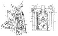
- FIG. 1is a front perspective view of an exercise device in accordance with the principles of the present invention.
- FIG. 2is a front perspective view of the exercise device of FIG. 1 with a shroud removed.
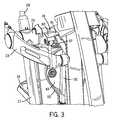
- FIG. 3is a detailed front perspective view of a portion of the exercise device of FIG. 1 .
- FIG. 4is a rear perspective view of the exercise device of FIG. 2 .
- FIG. 5is a graph of the non-linear profile of the stop point of the exercise device of FIG. 1 .
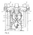
- FIG. 6is a detailed rear elevated view of a portion of the exercise device of FIG. 1 .
- FIG. 7is a detailed rear perspective view of another portion of the exercise device of FIG. 1 .
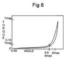
- FIG. 8is a torque versus angle graph of an end of travel stop assembly in accordance with the present invention.
- FIGS. 1-8illustrates an example embodiment of an exercise or fitness device suitable for use with the present invention. While the example embodiment described herein is a pendulum motion-type exercise device, the principles of the present invention apply to other fitness devices, particularly those in which the user is relatively mobile.
- a frame 12is provided that can include a basic supporting framework.
- the frame 12can be any structure that provides support for one or more components of the exercise device 10 .
- a pair of footpads 14is provided on which the user stands.
- a rear support base or platform 31can be provided connected to the frame 12 that provides further support to the exercise device 10 and acts as a step-up to the footpads 14 .
- the linkage pendulum system 15includes a lower and upper generally horizontal links 21 and 23 , a rear link member 18 , a forward generally vertical link 27 , and a pivot tube 25 (the pivot tube can be solid or hollow and it serves as a pivot axis).
- the footpad 14is coupled to a rear portion of the lower horizontal link 21 .
- the lower horizontal link 21serves as a footlink linking the footpad 14 to the remaining portions of the pendulum system 15 .
- the lower horizontal link 21swings or oscillates, but remains generally at or near horizontal, during use.
- the horizontal link 21is coupled near its rear end to a lower end of the rear link member 18 and is pivotally coupled at its forward end to the lower end of the forward vertical link 27 .
- the rear link member 18upwardly extends from its pivotal coupling with the lower horizontal link 21 in a generally vertical direction.
- the coupling of the rear link member 18 and the lower horizontal link 21can occur adjacent a forward portion of the footpad 14 .
- the upper end of the rear link member 18is pivotally coupled to a rear portion of the upper horizontal link 23 .
- the upper horizontal link 23extends generally horizontally and maintains a position that is generally parallel with the lower horizontal link 21 during use.
- a central region of the upper horizontal member 23is pivotally coupled to the pivot tube 25 , and a forward end of the upper horizontal member 23 is pivotally coupled to an upper end of a vertical resistance link 30 .
- the pivot tube 25is directly coupled to the frame 12 .
- the pivotal coupling of the central region of the upper horizontal member 23 to the pivot tube 25enables the rear portion of the upper horizontal member 23 (a cantilevered end region of the upper horizontal member 23 ) to be raised upward or downward during use thereby allowing for more pronounced available vertical motion to the exercise device 10 during use.
- the forward vertical link 27extends upward, generally vertically, from its coupling at its lower end to the forward end of the lower horizontal link 21 .
- the forward vertical link 27is pivotally coupled to the upper horizontal link 23 and the frame 12 at the pivot tube 25 .
- the rear link member 18 , the lower and upper horizontal links 21 and 23 , the forward vertical link 27 , and the pivot tube 25comprise the pivotal linkage pendulum system 15 .
- lower and upper horizontal links 21 and 23and the forward vertical link 27 incorporate the terms horizontal and vertical, these terms are intended to refer to the general orientation of these links.
- the lower and upper horizontal links 21 and 23 , and the forward vertical link 27will not always lie in a horizontal plane or a vertical plane, respectively. Rather, there positions will remain at or near the respective horizontal or vertical planes during use or while in a rest position.
- the resistance systems of the present Applicationare referred to in terms of vertical and horizontal resistance systems.
- the terms vertical and horizontal, in context of the resistance systems,are used in association with an embodiment of the invention, and the invention is not limited resistances systems that are directed to vertical and horizontal movements only. Rather, the present Application relates to first and second resistance systems, or primary and supplemental resistance systems.
- the orientation or application of the first and second resistance systemsis not limited to vertical and horizontal application only.
- the present inventioninvolves the application of a second or supplemental resistance system to improve the operation of an exercise device and is not limited to a specific orientation for the second or supplemental resistance application.
- a swing arm 29can be provided by extending the forward vertical link 27 above the pivot tube 25 a predetermined amount. The length and configuration of the swing arm 29 can be varied to match a desired motion and/or feel during use.
- An aesthetic shroud 33can partially cover the exercise device 10 .
- the pivotal linkage pendulum system 15 and the remaining components of the exercise deviceenable the user to increase or decrease the stride length or stride of the exercise device as desired.
- the footpads 14can be provided with toe clips 16 .
- the toe clips 16can be fixedly or removably connected to the foot pads 14 .
- the toe clip 16and be integrally formed with the foot pad 14 .
- the toe clips 16enable a user to easily and removably secure his or her foot on the footpad 14 while inhibiting forward movement or forward slippage of the user's foot during use. Accordingly, the toe clips 16 not only properly secure the user's feet with the exercise device 10 , but the toe clips 16 also enable the user to readily impart a forward force onto the footpad 14 with the toe clip 16 . In some configurations, the toe clips 14 can also enable the user to readily impart an upward force onto the toe clip 16 and foot pad 14 assembly. The user therefore can drive his or her foot forward and even upward without experiencing foot slippage. Additionally, by enabling the user to utilize these additional movements, additional large muscle group involvement is engaged throughout the exercise resulting in higher aerobic training effect. A still further benefit of the use of the toe clips is that more muscles can be exercised throughout the full range of motion rather than just during flexion or just during extension.
- FIG. 2shows the pendulum motion-type exercise device 10 with the shroud 33 removed.
- the upper end of the vertical resistance link 30is pivotally coupled to and extends generally vertically and downward from the forward end of the upper horizontal link 23 .
- the vertical resistance link 30is connected to a generally vertical resistance system 17 .
- the vertical resistance system 17can comprise a crank member 32 having a first end that is pivotally coupled to a lower end of the vertical resistance link 30 .
- a second end of the crank member 32is coupled to a shaft 35 .
- the back and forth motion of the lower horizontal link 21 , the rear link member 18 , and the forward vertical link 27typically includes at least some vertical component that causes the upper horizontal link 23 to pivot about its pivotal coupling to the pivot tube 25 .
- This pivotal movementcauses the forward end of the upper horizontal link 23 to oscillate upward and downward.
- these forcesalso cause the upper horizontal member 23 to pivot or oscillate about its pivotal coupling to the pivot tube 25 .
- the shaft 35 and the pivot tube 25each connect the left and right pivoting linkage pendulum systems 15 , and the shaft 35 connects the left and right crank members 32 causes the left and right upper horizontal links 23 to move in opposition to each other (i.e., the right movable member moves downwards as the left movable member moves upwards, and vice versa).
- the crank member 32is connected to a pulley system 34 , which includes an electronically controlled generator mounted to the frame 12 .
- the pulley system 34can be preferably operatively connected to a step-up pulley, a flywheel, and a generator system for applying a braking or retarding force, as known in the art.
- braking or retarding forcescan be applied using other mechanisms, such as for example an eddy current system, an alternator, friction brakes, fluid resistance, etc.
- a vertical resistanceis applied to the upper horizontal link 23 by means of the crank member 32 and the vertical resistance system 17 .
- an advantage of the exercise device of the present inventionis that it provides for horizontal resistance (a second or supplemental resistance).
- the present inventionprovides a horizontal resistance system 19 (a second or supplemental resistance system).
- a supplemental resistance link 41is provided pivotally coupled to the pivot tube 25 by a rocker link 60 which outwardly extends from the pivot tube 25 .
- the rocker link 60pivots in coordination with the pivoting movement of the upper horizontal link 23 about the pivot tube 25 .
- the supplemental resistance link 41is connected to the horizontal resistance system 19 .
- the horizontal resistance system 19can comprise a horizontal resistance pulley 43 .
- the horizontal resistance pulley 43comprises a rotating member pivotally coupled to the supplemental resistance link 41 opposite the pivot tube 25 .
- the supplemental resistance link 41is pivotally connected to the horizontal resistance pulley 43 near the outer periphery of the horizontal resistance pulley 43 ; thus the horizontal resistance pulley 43 acts as a crank member pivotally connecting the supplemental resistance link 41 and the horizontal resistance system 19 .
- the horizontal resistance pulley 43also acts to provided resistance to the horizontal resistance system.
- the horizontal resistance pulley 43is connected to a step-up pulley 45 and a flywheel 47 via a belt 50 .
- Tension on the belt 50can be maintained via an idler gear 52 .
- the flywheel 47can be a rotating metallic flywheel and resistance can be provided by an eddy current brake 49 (seen in FIGS. 6 and 7 ).
- the horizontal resistance pulley 43does not fully rotate in a complete 360 degree revolution; instead, the horizontal resistance pulley 43 rotates through an arch which is determined by the length of the stride of the user.
- the total rotation of the arch of the horizontal resistance pulley 43is relatively minimal; if the user takes a long stride length, the total rotation of the arch is relatively significant.
- the rotating horizontal resistance pulley 43By subjecting the rotating horizontal resistance pulley 43 to a means of resistance, the user is subjected to horizontal resistance in the fore and aft motions.
- the right and left footpads 14are synchronized about 180 degrees out of phase by the horizontal resistance pulley 43 , the supplemental resistance links 41 and the pivot shaft 25 . This synchronization results allow for foot motion that simulates climbing, walking, jogging or running to be achieved.
- the right and left footpads 14can be synchronized by a rocker link or other forms of couplings.
- the right and left footpads and the right and left linkage pendulum systemscan operate independent of each other or in a non-synchronous manner.
- a linear type resistance systemcan be used in place of the horizontal resistance pulley and related components.
- the link between the left and right footpads and the left and right linkage pendulum systemscan also be accomplished with compliance between the left and right providing a loose or flexible coupling between left and right motions.
- the movement of the left and right linkage pendulum systemscan be configured in a phased operating arrangement.
- the horizontal resistance system 19 of the present inventionpreferably provides adequate resistance to assist in stable foot motion, but not so much resistance as to make the fore and aft motion unnatural. Excessive resistance in the fore and/or aft directions can cause the foot path to distort in a vertical direction creating an unnatural foot path. In other instances, increased resistance in a fore and/or aft direction can make operation of the exercise device unsustainable for some users.
- the level of resistance at the foot pad or the foot of the user in the fore and aft directionis within the range of about 0.5 pounds of force to about 15 pounds of force. The level of resistance can be variable within this range or constant value within this range.
- variable resistancecan be user adjustable, programmed, time-dependent, or vary based upon other parameters.
- the level of resistance at the foot pad or the foot of the user in the fore and aft directionis within the range of about 2.0 pounds of force to about 10.0 pounds of force.
- the variable resistancecan be configured to vary based upon the velocity of the fore and aft motion of the foot pads or the linkage pendulum systems, or the variable resistance can vary based upon user selection, user programs or time or other parameters.
- the variation in resistancecan be obtained by effectively starting and stopping the rotating metallic flywheel 47 of the eddy current brake 49 for fore to aft or aft to fore motions.
- the metal flywheel 47is exposed to a magnetic field produced by permanent or electromagnets, generating eddy currents in the wheels.
- the magnetic interaction between the applied field and the eddy currentsacts to slow the metal flywheel 47 .
- a variable resistancecan be obtained through linear dampers (magnetic particle shock absorbers), pneumatic or hydraulic shock absorbers, or other non-constant resistance assemblies. Variability of resistance can also be provided by the start and stop of an inertial mass such as a larger flywheel without the need for additional resistance.
- a constant resistancecan be obtained by utilizing a rotating constant torque brake (magnetic particle rotating brake) or other form of friction resistance.
- an electronic controlled horizontal resistance brakecan be provided.
- Use of an electronic controlled horizontal resistance brakeallows for pre-determined variations in the resistance throughout the stride, a constant resistance throughout the stride or an overall variability on the effective resistance to assist in interval training.
- the range of usable resistance at the foot in the fore and aft directionswas found to be about 0.5 to about 15 pounds.
- a linear resistance systemcan be provided.
- the present inventionprovides a user with a variety of smooth natural available exercise paths or foot motions, exercises a relatively large number of muscles through a large range of motion, and provides such foot motions in a safe and stable manner.
- the present inventionalso provides an exercise device having available resistance in more than one general direction, such as resisted free travel in the fore and aft directions, without detracting from the unique engaging motion of the exercise device.
- the movement of the pivotal linkage pendulum system 15 of the exercise device 10also includes one or more stops for when the footpad 14 comes to the limit of the exercise device, also referred to as an end of travel stop, also referred to as an end of travel stop or an end of travel apparatus.
- an end of travel stopis too abrupt, an unsatisfactory jerking will occur to the user; indeed, if this stop is too abrupt and the user is utilizing a fast stride rate, the potential for injury to the user can increase. Accordingly, a need exists for an exercise device having a natural feeling end of travel stop. Applicants have determined that it is preferred that the end of travel have a two-stage linear stiffness profile or a non-linear stiffness profile.
- This profileis graphed in FIG. 5 .
- force in poundsis set forth on the vertical axis and travel in inches is set forth on the vertical axis. It is seen that as the travel increases the force in pounds is initially relatively flat, thereby providing the user with a gentle indication of the end of travel. Then, the force in pounds increases rapidly as the pre-determined stop point is approached. The softer initial contact can also provide a turn-around push for the user, as well as a smooth non-forceful signal that the end of travel is approaching.
- the rocker link 60includes stop tab 61 configured to engage a first bumper 57 .
- the first bumper 57serves as an end of travel stop that provides a highly stiff cushion and a rather abrupt stop when the stop tab 61 fully engages the first bumper 57 .
- the exercise device 10also includes left and right rocker links 61 , supplemental resistance links 41 and first bumpers 57 .
- each of the second bumper 62 and 64is configured to be relatively soft for the initial contact as the end of travel is approached and then becomes relatively stiff, or increasingly stiff, as the actual end of travel is approached.
- the first bumper 57 , and the second bumpers 62 and 64are preferably formed of an elastic material such as a polyester elastomer.
- the first and/or second bumperscan be formed of other materials such as, for example, butyl rubber, polyurethane, other elastomers, or combinations thereof.
- the elastic properties of the second bumpers 62 and 64enable the bumpers to provide a gentle push to the user as the user reverses directions at the end of travel position.
- the gentle pushimproves the feel and comfort of the exercise device 10 and makes the exercise device more enjoyable to use.
- the second bumpers 62 and 64 and the first bumpers 57provide an optimal two stage end of travel stop configuration for an exercise device in both the fore direction and the aft direction.
- the second bumpers 62 and 64provide the initial soft end of travel indication that non-linearly increases if travel continues in the stop direction, and the first bumpers 57 provide the abrupt stop to ensure that the maximum travel of the exercise device is not exceeded, and the exercise device is not damaged, while minimizing the negative impact or feel to the user.
- a bumper bracket 66can be provided extending over the horizontal resistance pulley 43 .
- the bumper bracket 66contains two contact surfaces 72 , 74 adapted to contact and bear against the second bumpers 62 and 64 .
- the second bumpers 62 and 64are held in brackets 82 , 84 having surfaces 85 and 87 , respectively, contained on the horizontal resistance pulley 43 .
- the end of travel stop or apparatusis configured to provide a predetermined range of travel after the linkage assembly first contacts the end of travel apparatus.
- the end of travel apparatusprovides first and second ranges of resistance resisting the travel of the linkage assembly over first and second portions of the predetermined range of travel, respectively.
- One example, of the first and second ranges of resistanceis shown on FIG. 5 .
- the first and second ranges of resistancecollectively provide a progressive, non-linear stiffness profile to the end of travel apparatus.
- the first range of resistanceis less than 1000 pounds of force over the first eighty (80) percent of the predetermined range of travel.
- the predetermined range of travel of the end of travel stopcan be within the range of greater than or equal to one inch to less than or equal to three inches.
- the predetermined range of travel of the end of travel stopcan be within the range of greater than or equal to 1.5 inches to less than or equal to 2.5 inches.
- the first range of resistanceis less than 1000 pounds of force over one of the first seventy (70) percent, the first sixty (60) percent or the first fifty (50) percent of the predetermined range of travel.
- the amount of force in pounds applied by the end of travel stop in the second range of resistanceis at least 300 percent greater than the amount of force in pounds applied by the end of travel apparatus in the first range of resistance.
- the second range of resistancecan extends over the last forty percent, the last thirty percent or the last twenty percent of the predetermined range of travel.
- the second range of resistancecan be at least 400 percent greater, or at least 500 percent greater, than the amount of force in pounds applied by the end of travel apparatus in the first range of resistance.
- the end of travel apparatusurges the linkage assembly in a direction opposite the direction at initial contact with the end of travel apparatus after the foot member reaches an initial end of travel position.
- the second bumpers 62 and 64are each configured to provide a rebound or a push back in the opposite direction to the horizontal resistance pulley 43 , which is ultimately felt by the user during use. This push improves the feel of the exercise device and further reduces any negative feedback resulting from engaging the end of travel stop or apparatus.
- the end of travel apparatus or assemblypreferably provides a coefficient of restitution (“COR”) of at least 0.60 percent.
- CORis a measure of energy loss or retention, and refers to the ratio of outgoing energy (also displayed in terms of speed or force) to incoming energy (also speed or force) of the linkage assembly engaging the end of travel apparatus or assembly.
- the end of travel apparatus or assemblyproduces a COR of at least 0.70.
- FIG. 8illustrates the non-linear end of travel stop assembly configuration of the present invention in an alternate manner.
- the progressive, non-linear response of the end of travel stop assembly in resistance to the movement of the linkage assemblycan be represented in terms of torque versus angle, as shown in FIG. 8 .
- the torque v. angle graphclearly demonstrates the two-stage performance of the end of travel stop assembly.
- the total amount of angular travel of the linkage assembly after making contact with the end of travel stop assemblycan be defined in terms of an angular value of theta max ( ⁇ max ) and the total amount of torque applied in resistance to the angular movement of the linkage can be defined in terms of a maximum torque value (T max ).
- the first stage of the end of travel assemblycan be defined by an amount of angular travel equivalent to approximately 0.8 ⁇ max (or 80 percent), which corresponds to an amount of torque that is approximately 0.15 T max (or 15 percent).
- a torque value of approximately 0.15 T maxcan correspond to angular values as low as 0.6 ⁇ max (or 60 percent) to as high as 0.95 ⁇ max (or 95 percent)
- the torque value of approximately 0.15 T maxcan correspond to angular values as low as 0.7 ⁇ max (or 70 percent) to as high as 0.9 ⁇ max (or 90 percent).
- the angular displacement of 0.8 ⁇ maxcan correspond to a torque value within the range of greater than or equal to 0.05 T max to 0.25 T max .
- the maximum torque value T maxcan be 55,000 in-lbs and the maximum angular deflection of the end of travel stop assembly (such as a bumper assembly) can be approximately 20 degrees.
- other values for maximum torque value T max and total angular deflection ⁇ maxcan also be used. These values can be configured to match the particular exercise device and a particular application of such an exercise device provided that the non-linear progressive torque versus angle performance characteristic is achieved.
- the first bumper 57can be provided with the non-linear response such that initial contact by the stop tab 61 is soft providing a gentle indication of the end of stop, then the first bumper 57 can be configured to have a non-linear increase in resistance if and when the stop tab 61 continues to engage the first bumper 57 and continues to bear against the first bumper 57 .
- Both the single bumper and the dual bumper methodsprovide a unique feel that is crucial to a user defined motion exercise device. By correctly selecting the initial stiffness, the user does not sense the foot motion is approaching the end of travel, but instead senses a resistance that begins to urge the foot into the opposite direction.
- the end of travel “push”tends to help the user to maintain a smooth and rhythmical motion required to achieve highly aerobic workout even while striding out to a maximum stride length.
Landscapes
- Health & Medical Sciences (AREA)
- General Health & Medical Sciences (AREA)
- Physical Education & Sports Medicine (AREA)
- Cardiology (AREA)
- Vascular Medicine (AREA)
- Orthopedic Medicine & Surgery (AREA)
- Rehabilitation Tools (AREA)
Abstract
Description
Claims (40)
Priority Applications (3)
| Application Number | Priority Date | Filing Date | Title |
|---|---|---|---|
| US11/646,882US7833133B2 (en) | 2006-12-28 | 2006-12-28 | End of travel stop for an exercise device |
| US12/899,319US8105213B2 (en) | 2006-12-28 | 2010-10-06 | End of travel stop for an exercise device |
| US14/691,532US9724566B2 (en) | 2006-12-28 | 2015-04-20 | Exercise device path traces |
Applications Claiming Priority (1)
| Application Number | Priority Date | Filing Date | Title |
|---|---|---|---|
| US11/646,882US7833133B2 (en) | 2006-12-28 | 2006-12-28 | End of travel stop for an exercise device |
Related Child Applications (1)
| Application Number | Title | Priority Date | Filing Date |
|---|---|---|---|
| US12/899,319ContinuationUS8105213B2 (en) | 2006-12-28 | 2010-10-06 | End of travel stop for an exercise device |
Publications (2)
| Publication Number | Publication Date |
|---|---|
| US20080161164A1 US20080161164A1 (en) | 2008-07-03 |
| US7833133B2true US7833133B2 (en) | 2010-11-16 |
Family
ID=39584828
Family Applications (2)
| Application Number | Title | Priority Date | Filing Date |
|---|---|---|---|
| US11/646,882Active2027-11-09US7833133B2 (en) | 2006-12-28 | 2006-12-28 | End of travel stop for an exercise device |
| US12/899,319ActiveUS8105213B2 (en) | 2006-12-28 | 2010-10-06 | End of travel stop for an exercise device |
Family Applications After (1)
| Application Number | Title | Priority Date | Filing Date |
|---|---|---|---|
| US12/899,319ActiveUS8105213B2 (en) | 2006-12-28 | 2010-10-06 | End of travel stop for an exercise device |
Country Status (1)
| Country | Link |
|---|---|
| US (2) | US7833133B2 (en) |
Cited By (24)
| Publication number | Priority date | Publication date | Assignee | Title |
|---|---|---|---|---|
| US20100317492A1 (en)* | 2009-06-12 | 2010-12-16 | Nelson Derek L | Elliptical exercise machine |
| US20110124472A1 (en)* | 2006-09-15 | 2011-05-26 | Mckee Todd | Machines and Methods for Combined and Isolated Upper and Lower Body Workouts |
| USD687911S1 (en)* | 2012-02-28 | 2013-08-13 | Precor Incorporated | Exercise device |
| USD690375S1 (en) | 2012-02-28 | 2013-09-24 | Precor Incorporated | Exercise device |
| US8540609B2 (en)* | 2006-03-13 | 2013-09-24 | Brunswick Corporation | Climber appliance |
| USD690784S1 (en) | 2012-02-28 | 2013-10-01 | Precor Incorporated | Exercise device |
| USD703278S1 (en) | 2012-02-28 | 2014-04-22 | Precor Incorporated | Exercise device |
| US20140141939A1 (en)* | 2012-11-21 | 2014-05-22 | Strength Master Fitness Tech Co., Ltd. | Treading exerciser and method for controlling resistance of the treading exerciser |
| US20160001124A1 (en)* | 2014-07-01 | 2016-01-07 | Rexon Industrial Corp., Ltd. | Fitness equipment |
| US9295874B1 (en)* | 2014-11-24 | 2016-03-29 | Yi-Tzu Chen | Elliptical trainer |
| US20160346598A1 (en)* | 2015-06-01 | 2016-12-01 | Johnson Health Tech Co., Ltd | Exercise apparatus |
| US9597540B2 (en) | 2012-02-14 | 2017-03-21 | Precor Incorporated | Adaptive motion exercise device |
| US9643044B1 (en)* | 2015-12-03 | 2017-05-09 | Great Fitness Industrial Co., Ltd. | Damping device for exercise equipment |
| USD843503S1 (en)* | 2017-06-27 | 2019-03-19 | Kai Bin Xing | Elliptical exercise machine |
| US10556169B2 (en) | 2018-05-21 | 2020-02-11 | The Giovanni Project LLC | Locking system for a treadmill |
| US10722752B2 (en) | 2018-05-21 | 2020-07-28 | The Giovanni Project LLC | Treadmill with lighting and safety features |
| US11083924B2 (en)* | 2018-04-05 | 2021-08-10 | British Columbia Institute Of Technology | Active arm passive leg exercise machine with guided leg movement |
| US11154746B2 (en) | 2015-06-01 | 2021-10-26 | Johnson Health Tech Co., Ltd. | Exercise apparatus |
| US11224781B2 (en) | 2019-02-28 | 2022-01-18 | The Giovanni Project LLC | Treadmill with lighted slats and power disks |
| US11291881B2 (en) | 2019-02-28 | 2022-04-05 | The Giovanni Project LLC | Treadmill with lighted slats |
| US20220203158A1 (en)* | 2020-12-24 | 2022-06-30 | ALT Innovations LLC | Upper body gait ergometer and gait trainer |
| US11590388B2 (en) | 2018-05-21 | 2023-02-28 | The Giovanni Project LLC | Braking and locking system for a treadmill |
| US11918847B2 (en) | 2018-05-21 | 2024-03-05 | The Giovanni Project LLC | Braking and locking system for a treadmill |
| US12005302B2 (en) | 2015-06-01 | 2024-06-11 | Johnson Health Tech Co., Ltd | Exercise apparatus |
Families Citing this family (49)
| Publication number | Priority date | Publication date | Assignee | Title |
|---|---|---|---|---|
| US8109861B2 (en)* | 2006-08-10 | 2012-02-07 | Exerciting, Llc | Exercise device with varied gait movements |
| US7874963B2 (en)* | 2008-12-29 | 2011-01-25 | Precor Incorporated | Exercise device with adaptive curved track motion |
| US7922625B2 (en)* | 2008-12-29 | 2011-04-12 | Precor Incorporated | Adaptive motion exercise device with oscillating track |
| JP5770714B2 (en)* | 2009-04-15 | 2015-08-26 | プリコー インコーポレイテッドPrecor, Inc. | Exercise device with flexible element |
| US20130053223A1 (en)* | 2011-08-30 | 2013-02-28 | Liao Lai Shu-Chiung | Training apparatus for a bicycle |
| US20130231217A1 (en)* | 2012-03-05 | 2013-09-05 | Larry D. Miller Trust | Adaptive exercise device with variable components of motion |
| EP2735344A1 (en)* | 2012-11-22 | 2014-05-28 | Strength Master Fitness Tech Co., Ltd. | Treading exerciser and method for controlling resistance of the treading exerciser |
| TW201427749A (en)* | 2013-01-07 | 2014-07-16 | Dyaco Int Inc | Exercise device with leg elliptical orbit |
| US9114275B2 (en) | 2013-03-04 | 2015-08-25 | Brunswick Corporation | Exercise assemblies having crank members with limited rotation |
| US9138614B2 (en) | 2013-03-04 | 2015-09-22 | Brunswick Corporation | Exercise assemblies having linear motion synchronizing mechanism |
| US9050498B2 (en)* | 2013-03-04 | 2015-06-09 | Brunswick Corporation | Exercise assemblies having foot pedal members that are movable along user defined paths |
| WO2014153158A1 (en) | 2013-03-14 | 2014-09-25 | Icon Health & Fitness, Inc. | Strength training apparatus with flywheel and related methods |
| USD742977S1 (en)* | 2013-08-29 | 2015-11-10 | Octane Fitness, Llc | Stationary exercise machine |
| CA2860427C (en) | 2013-08-29 | 2020-02-25 | Octane Fitness, Llc | Lower body mimetic exercise device with fully or partially autonomous right and left leg links and ergonomically positioned pivot points |
| CN105764579B (en)* | 2013-09-11 | 2017-12-08 | 赛百斯国际健身器材有限公司 | exercise equipment |
| CN105848733B (en) | 2013-12-26 | 2018-02-13 | 爱康保健健身有限公司 | Magnetic resistance mechanism in hawser apparatus |
| US10433612B2 (en) | 2014-03-10 | 2019-10-08 | Icon Health & Fitness, Inc. | Pressure sensor to quantify work |
| WO2015191445A1 (en) | 2014-06-09 | 2015-12-17 | Icon Health & Fitness, Inc. | Cable system incorporated into a treadmill |
| TWI535476B (en)* | 2014-06-30 | 2016-06-01 | 力山工業股份有限公司 | Elliptical trainer |
| US9682277B2 (en) | 2014-12-10 | 2017-06-20 | Fit-Novation, Inc. | Exercise device |
| US10258828B2 (en) | 2015-01-16 | 2019-04-16 | Icon Health & Fitness, Inc. | Controls for an exercise device |
| US10537764B2 (en) | 2015-08-07 | 2020-01-21 | Icon Health & Fitness, Inc. | Emergency stop with magnetic brake for an exercise device |
| US10953305B2 (en) | 2015-08-26 | 2021-03-23 | Icon Health & Fitness, Inc. | Strength exercise mechanisms |
| EP3167942B1 (en)* | 2015-11-13 | 2019-07-03 | Lai, Yu-Chen | Elliptical exerciser |
| US10046197B2 (en) | 2015-11-19 | 2018-08-14 | Fitnovation, Inc. | Exercise device |
| US9579537B1 (en)* | 2015-12-09 | 2017-02-28 | Mario Contenti Designs Co., Ltd. | Elliptical trainer with changeable foot motion |
| US10272317B2 (en) | 2016-03-18 | 2019-04-30 | Icon Health & Fitness, Inc. | Lighted pace feature in a treadmill |
| US10561894B2 (en) | 2016-03-18 | 2020-02-18 | Icon Health & Fitness, Inc. | Treadmill with removable supports |
| US10293211B2 (en) | 2016-03-18 | 2019-05-21 | Icon Health & Fitness, Inc. | Coordinated weight selection |
| US10493349B2 (en) | 2016-03-18 | 2019-12-03 | Icon Health & Fitness, Inc. | Display on exercise device |
| US10625137B2 (en) | 2016-03-18 | 2020-04-21 | Icon Health & Fitness, Inc. | Coordinated displays in an exercise device |
| US10252109B2 (en) | 2016-05-13 | 2019-04-09 | Icon Health & Fitness, Inc. | Weight platform treadmill |
| US10471299B2 (en) | 2016-07-01 | 2019-11-12 | Icon Health & Fitness, Inc. | Systems and methods for cooling internal exercise equipment components |
| US10441844B2 (en) | 2016-07-01 | 2019-10-15 | Icon Health & Fitness, Inc. | Cooling systems and methods for exercise equipment |
| US10500473B2 (en) | 2016-10-10 | 2019-12-10 | Icon Health & Fitness, Inc. | Console positioning |
| US10376736B2 (en) | 2016-10-12 | 2019-08-13 | Icon Health & Fitness, Inc. | Cooling an exercise device during a dive motor runway condition |
| US10625114B2 (en) | 2016-11-01 | 2020-04-21 | Icon Health & Fitness, Inc. | Elliptical and stationary bicycle apparatus including row functionality |
| TWI637770B (en) | 2016-11-01 | 2018-10-11 | 美商愛康運動與健康公司 | Drop-in pivot configuration for stationary bikes |
| TWI646997B (en) | 2016-11-01 | 2019-01-11 | 美商愛康運動與健康公司 | Distance sensor for console positioning |
| US10661114B2 (en) | 2016-11-01 | 2020-05-26 | Icon Health & Fitness, Inc. | Body weight lift mechanism on treadmill |
| TWI680782B (en) | 2016-12-05 | 2020-01-01 | 美商愛康運動與健康公司 | Offsetting treadmill deck weight during operation |
| US10702736B2 (en) | 2017-01-14 | 2020-07-07 | Icon Health & Fitness, Inc. | Exercise cycle |
| US11451108B2 (en) | 2017-08-16 | 2022-09-20 | Ifit Inc. | Systems and methods for axial impact resistance in electric motors |
| TWI640341B (en)* | 2017-10-20 | 2018-11-11 | 岱宇國際股份有限公司 | Elliptical trainer |
| US10729965B2 (en) | 2017-12-22 | 2020-08-04 | Icon Health & Fitness, Inc. | Audible belt guide in a treadmill |
| TWI738110B (en)* | 2019-11-08 | 2021-09-01 | 眾成工業股份有限公司 | Elliptical machine that meets human factors engineering |
| TWM596645U (en)* | 2020-02-25 | 2020-06-11 | 亞得健康科技股份有限公司 | Treadmill with cushioning assistance |
| USD1085286S1 (en)* | 2024-04-16 | 2025-07-22 | Zheng Xing (Tongxiang) Health Technology Co., Ltd. | Elliptical machine |
| USD1080771S1 (en)* | 2024-07-11 | 2025-06-24 | Hangzhou Xinyuan Electronic Technology Co., Ltd. | Elliptical machine |
Citations (76)
| Publication number | Priority date | Publication date | Assignee | Title |
|---|---|---|---|---|
| US3807727A (en)* | 1972-06-29 | 1974-04-30 | L Ferguson | Programmed skiing simulator, trainer and exerciser |
| US4934690A (en)* | 1988-04-13 | 1990-06-19 | Bull John W | Shock-free aerobic and anaerobic exercising machine for use in the standing position |
| US5238462A (en)* | 1991-02-20 | 1993-08-24 | Life Fitness | Stair climbing exercise apparatus utilizing drive belts |
| US5314390A (en)* | 1992-01-31 | 1994-05-24 | Loredan Biomedical, Inc. | Linear tracking programmable exerciser |
| US5318490A (en)* | 1991-03-15 | 1994-06-07 | Precor Incorporated | Exercise apparatus |
| US5368533A (en)* | 1993-05-13 | 1994-11-29 | Fittraxx | Quadrilateral exercise apparatus |
| US5374227A (en)* | 1993-01-19 | 1994-12-20 | Nautilus Acquisition Corporation | Stair stepping exercise apparatus |
| US5385063A (en)* | 1993-05-13 | 1995-01-31 | Greenmaster Industrial Corp. | Transmission mechanism for magnetic damping type step machine |
| US5419751A (en)* | 1993-10-28 | 1995-05-30 | Stamina Products, Inc. | Multi-function exercise apparatus |
| US5501646A (en)* | 1994-08-26 | 1996-03-26 | W. G. Miller Associates | Jaw, face and neck muscle exercise apparatus |
| US5577985A (en)* | 1996-02-08 | 1996-11-26 | Miller; Larry | Stationary exercise device |
| US5653662A (en)* | 1996-05-24 | 1997-08-05 | Rodgers, Jr.; Robert E. | Stationary exercise apparatus |
| US5735774A (en)* | 1995-07-19 | 1998-04-07 | Maresh; Joseph Douglas | Active crank axis cycle mechanism |
| US5749807A (en)* | 1993-01-19 | 1998-05-12 | Nautilus Acquisition Corporation | Exercise apparatus and associated method including rheological fluid brake |
| US5769760A (en)* | 1997-07-22 | 1998-06-23 | Lin; Michael | Stationary exercise device |
| US5788610A (en)* | 1996-09-09 | 1998-08-04 | Eschenbach; Paul William | Elliptical exercise machine with arm exercise |
| US5795268A (en)* | 1995-12-14 | 1998-08-18 | Husted; Royce H. | Low impact simulated striding device |
| US5846166A (en)* | 1998-04-13 | 1998-12-08 | Kuo; Hui Kuei | Stepping exercise mechanism |
| US5848954A (en)* | 1997-04-15 | 1998-12-15 | Stearns; Kenneth W. | Exercise methods and apparatus |
| US5857941A (en)* | 1997-04-15 | 1999-01-12 | Maresh; Joseph D. | Exercise methods and apparatus |
| US5868650A (en)* | 1998-01-05 | 1999-02-09 | Wu; Hsin-Shu | Stationary exercise device |
| US5911649A (en)* | 1996-02-08 | 1999-06-15 | Miller; Larry | Stationary exercise device |
| US5989159A (en)* | 1998-01-22 | 1999-11-23 | Chen; James | Exercise device |
| US6004244A (en)* | 1997-02-13 | 1999-12-21 | Cybex International, Inc. | Simulated hill-climbing exercise apparatus and method of exercising |
| US6042512A (en)* | 1999-07-27 | 2000-03-28 | Eschenbach; Paul William | Variable lift cross trainer exercise apparatus |
| US6045487A (en)* | 1996-02-08 | 2000-04-04 | Miller; Larry | Exercise apparatus |
| US6077197A (en)* | 1998-05-05 | 2000-06-20 | Stearns; Kenneth W. | Semi-recumbent exercise apparatus with elliptical motion |
| US6123650A (en)* | 1998-11-03 | 2000-09-26 | Precor Incorporated | Independent elliptical motion exerciser |
| US6132339A (en)* | 1999-10-18 | 2000-10-17 | Wang; Leao | Treading fitness trainer |
| US6165107A (en)* | 1999-03-18 | 2000-12-26 | Illinois Tool Works Inc. | Flexibly coordinated motion elliptical exerciser |
| US6183397B1 (en)* | 1999-05-25 | 2001-02-06 | Kenneth W. Stearns | Multi-functional exercise methods and apparatus |
| US6210305B1 (en)* | 1999-07-27 | 2001-04-03 | Paul William Eschenbach | Variable lift exercise apparatus with curved guide |
| US6248045B1 (en)* | 1997-03-31 | 2001-06-19 | Kenneth W. Stearns | Exercise method and apparatus |
| US6270445B1 (en)* | 1999-02-03 | 2001-08-07 | Simbex Llc | In-bed exercise machine and method of use |
| US6338698B1 (en)* | 1997-04-26 | 2002-01-15 | Kenneth W. Stearns | Exercise method and apparatus with an adjustable crank |
| US6340340B1 (en)* | 1997-04-15 | 2002-01-22 | Kenneth W. Stearns | Exercise method and apparatus |
| US20020019298A1 (en)* | 1997-06-09 | 2002-02-14 | Eschenbach Paul William | Pathfinder elliptical exercise machine |
| US20020142889A1 (en)* | 2001-03-28 | 2002-10-03 | Mu-Chuan Wu | Transmitting device for a walking machine |
| US20020142890A1 (en)* | 2001-03-30 | 2002-10-03 | Ohrt John Arthur | Exercise machine |
| US6641506B1 (en)* | 2002-05-24 | 2003-11-04 | Chang-Hsin Yang | Walking machine having two footboards capable of swiveling laterally |
| US20040043871A1 (en)* | 2002-08-30 | 2004-03-04 | Huang-Tung Chang | Treading exercising machine with adjustable elliptical track for tilting at two sides |
| US20040053748A1 (en)* | 2002-09-12 | 2004-03-18 | Kun-Chuan Lo | Hand support controlling device for an elliptical exercise apparatus |
| US20040058784A1 (en)* | 2001-07-11 | 2004-03-25 | Roberts Robert E. | Stationary type of exercise apparatus that enables movement of the user's feet in a reciprocating motion |
| US6758790B1 (en)* | 2002-09-04 | 2004-07-06 | Northland Industries, Inc. | Low impact walking/jogging exercise machine |
| US20040157706A1 (en)* | 2003-02-06 | 2004-08-12 | Miller Larry D. | Non-reciprocating exercise device |
| US6786851B1 (en)* | 1997-04-26 | 2004-09-07 | Joseph D. Maresh | Exercise apparatus with elliptical stepping motion |
| US20040266587A1 (en)* | 2003-06-27 | 2004-12-30 | Miller Larry D. | Elliptical exercise device with movable pivot axis |
| US6849033B1 (en)* | 1997-04-24 | 2005-02-01 | Kenneth W. Stearns | Exercise methods and apparatus |
| US20050049117A1 (en)* | 2003-08-29 | 2005-03-03 | Rodgers Robert E. | Striding simulators |
| US20050124467A1 (en) | 2003-12-04 | 2005-06-09 | Rodgers Robert E.Jr. | Pendulum striding exercise devices |
| US20050124466A1 (en) | 2003-12-04 | 2005-06-09 | Rodgers Robert E.Jr. | Pendulum striding exercise apparatus |
| US20050181912A1 (en)* | 2002-11-26 | 2005-08-18 | Eschenbach Paul W. | Elliptical exercise apparatus with adjustable crank |
| US6949054B1 (en)* | 2003-06-26 | 2005-09-27 | Stearns Kenneth W | Exercise methods and apparatus with elliptical foot motion |
| US20060003868A1 (en)* | 2003-06-23 | 2006-01-05 | Nautilus, Inc. | Releasable connection mechanism for variable stride exercise devices |
| US20060009330A1 (en)* | 2004-07-08 | 2006-01-12 | Chiu-Hsiang Lo | Mold changeable elliptical exercisers |
| US6994657B1 (en)* | 2005-03-17 | 2006-02-07 | Paul William Eschenbach | Elliptical exercise machine |
| US20060100066A1 (en)* | 1995-06-30 | 2006-05-11 | Maresh Joseph D | Exercise methods and apparatus |
| US20060142123A1 (en)* | 2004-12-03 | 2006-06-29 | Joachim Kettler | Training apparatus, in particular an elliptical trainer or cross trainer |
| US20060142122A1 (en)* | 2004-12-03 | 2006-06-29 | Karin Kettler | Training apparatus, in particular an elliptical or cross trainer |
| US20060172862A1 (en)* | 2003-06-05 | 2006-08-03 | Flexiped As | Physical exercise apparatus and footrest platform for use with the apparatus |
| US7121984B1 (en)* | 2005-06-27 | 2006-10-17 | Chou Hong | Convertible stepping exerciser |
| US20060281604A1 (en)* | 2005-06-08 | 2006-12-14 | Precor Incorporated | Cross training exercise device |
| US20070087906A1 (en)* | 2003-06-06 | 2007-04-19 | Rodgers Robert E Jr | Variable stride exercise apparatus |
| US20070117684A1 (en)* | 2005-11-04 | 2007-05-24 | Hung-Mao Liao | Stationary exercise apparatus |
| US20070117686A1 (en)* | 2005-11-04 | 2007-05-24 | Hung-Mao Liao | Stationary exercise apparatus |
| US20070117685A1 (en)* | 2005-11-04 | 2007-05-24 | Hung-Mao Liao | Stationary exercise apparatus |
| US20070135268A1 (en)* | 2005-12-12 | 2007-06-14 | Leao Wang | Treadle assembly of an exercise equipment |
| US7238146B1 (en)* | 2006-07-25 | 2007-07-03 | James Chen | Elliptical exercise apparatus |
| US20070161463A1 (en)* | 2006-01-12 | 2007-07-12 | Eschenbach Paul W | Step through recumbent elliptical exercise apparatus |
| US20070161465A1 (en)* | 2006-01-12 | 2007-07-12 | Paul William Eschenbach | Step thru recumbent elliptical exercise apparatus |
| US20070179023A1 (en)* | 2006-01-30 | 2007-08-02 | Precor Incorporated | Cross training exercise device |
| US20070219065A1 (en)* | 2006-03-13 | 2007-09-20 | Anderson Timothy T | Climber apparatus |
| US20070219062A1 (en)* | 2006-03-09 | 2007-09-20 | Rodgers Robert E | Translating support assembly systems and methods for use thereof |
| US20070219061A1 (en)* | 2006-03-09 | 2007-09-20 | Rodgers Jr Robert E | Variable geometry flexible support systems and methods for use thereof |
| US20070238580A1 (en)* | 2006-03-29 | 2007-10-11 | Leao Wang | Pace-adjusting mechanism of an elliptical cross trainer |
| USD559925S1 (en)* | 2006-12-28 | 2008-01-15 | Precor Incorporated | Exercise device |
- 2006
- 2006-12-28USUS11/646,882patent/US7833133B2/enactiveActive
- 2010
- 2010-10-06USUS12/899,319patent/US8105213B2/enactiveActive
Patent Citations (87)
| Publication number | Priority date | Publication date | Assignee | Title |
|---|---|---|---|---|
| US3807727A (en)* | 1972-06-29 | 1974-04-30 | L Ferguson | Programmed skiing simulator, trainer and exerciser |
| US4934690A (en)* | 1988-04-13 | 1990-06-19 | Bull John W | Shock-free aerobic and anaerobic exercising machine for use in the standing position |
| US4934690B1 (en)* | 1988-04-13 | 1995-04-04 | John W Bull | Shock-free aerobic and anaerobic exercising machine for use in the standing position |
| US5238462A (en)* | 1991-02-20 | 1993-08-24 | Life Fitness | Stair climbing exercise apparatus utilizing drive belts |
| US5318490A (en)* | 1991-03-15 | 1994-06-07 | Precor Incorporated | Exercise apparatus |
| US5314390A (en)* | 1992-01-31 | 1994-05-24 | Loredan Biomedical, Inc. | Linear tracking programmable exerciser |
| US5749807A (en)* | 1993-01-19 | 1998-05-12 | Nautilus Acquisition Corporation | Exercise apparatus and associated method including rheological fluid brake |
| US5374227A (en)* | 1993-01-19 | 1994-12-20 | Nautilus Acquisition Corporation | Stair stepping exercise apparatus |
| US5368533A (en)* | 1993-05-13 | 1994-11-29 | Fittraxx | Quadrilateral exercise apparatus |
| US5385063A (en)* | 1993-05-13 | 1995-01-31 | Greenmaster Industrial Corp. | Transmission mechanism for magnetic damping type step machine |
| US5419751A (en)* | 1993-10-28 | 1995-05-30 | Stamina Products, Inc. | Multi-function exercise apparatus |
| US5501646A (en)* | 1994-08-26 | 1996-03-26 | W. G. Miller Associates | Jaw, face and neck muscle exercise apparatus |
| US20060100066A1 (en)* | 1995-06-30 | 2006-05-11 | Maresh Joseph D | Exercise methods and apparatus |
| US7137927B2 (en)* | 1995-06-30 | 2006-11-21 | Maresh Joseph D | Exercise methods and apparatus |
| US20060100065A1 (en)* | 1995-06-30 | 2006-05-11 | Maresh Joseph D | Exercise methods and apparatus |
| US5735774A (en)* | 1995-07-19 | 1998-04-07 | Maresh; Joseph Douglas | Active crank axis cycle mechanism |
| US5857940A (en)* | 1995-12-14 | 1999-01-12 | Husted; Royce H. | Low impact simulated striding device |
| US5795268A (en)* | 1995-12-14 | 1998-08-18 | Husted; Royce H. | Low impact simulated striding device |
| US5577985A (en)* | 1996-02-08 | 1996-11-26 | Miller; Larry | Stationary exercise device |
| US6045487A (en)* | 1996-02-08 | 2000-04-04 | Miller; Larry | Exercise apparatus |
| US5911649A (en)* | 1996-02-08 | 1999-06-15 | Miller; Larry | Stationary exercise device |
| US5653662A (en)* | 1996-05-24 | 1997-08-05 | Rodgers, Jr.; Robert E. | Stationary exercise apparatus |
| US5788610A (en)* | 1996-09-09 | 1998-08-04 | Eschenbach; Paul William | Elliptical exercise machine with arm exercise |
| US6004244A (en)* | 1997-02-13 | 1999-12-21 | Cybex International, Inc. | Simulated hill-climbing exercise apparatus and method of exercising |
| US6248045B1 (en)* | 1997-03-31 | 2001-06-19 | Kenneth W. Stearns | Exercise method and apparatus |
| US5848954A (en)* | 1997-04-15 | 1998-12-15 | Stearns; Kenneth W. | Exercise methods and apparatus |
| US5857941A (en)* | 1997-04-15 | 1999-01-12 | Maresh; Joseph D. | Exercise methods and apparatus |
| US6340340B1 (en)* | 1997-04-15 | 2002-01-22 | Kenneth W. Stearns | Exercise method and apparatus |
| US6849033B1 (en)* | 1997-04-24 | 2005-02-01 | Kenneth W. Stearns | Exercise methods and apparatus |
| US6338698B1 (en)* | 1997-04-26 | 2002-01-15 | Kenneth W. Stearns | Exercise method and apparatus with an adjustable crank |
| US20060247103A1 (en)* | 1997-04-26 | 2006-11-02 | Stearns Kenneth K | Elliptical exercise methods and apparatus with adjustable crank |
| US6786851B1 (en)* | 1997-04-26 | 2004-09-07 | Joseph D. Maresh | Exercise apparatus with elliptical stepping motion |
| US6440042B2 (en)* | 1997-06-09 | 2002-08-27 | Paul William Eschenbach | Pathfinder elliptical exercise machine |
| US20020019298A1 (en)* | 1997-06-09 | 2002-02-14 | Eschenbach Paul William | Pathfinder elliptical exercise machine |
| US5769760A (en)* | 1997-07-22 | 1998-06-23 | Lin; Michael | Stationary exercise device |
| US5868650A (en)* | 1998-01-05 | 1999-02-09 | Wu; Hsin-Shu | Stationary exercise device |
| US5989159A (en)* | 1998-01-22 | 1999-11-23 | Chen; James | Exercise device |
| US5846166A (en)* | 1998-04-13 | 1998-12-08 | Kuo; Hui Kuei | Stepping exercise mechanism |
| US6077197A (en)* | 1998-05-05 | 2000-06-20 | Stearns; Kenneth W. | Semi-recumbent exercise apparatus with elliptical motion |
| US6123650A (en)* | 1998-11-03 | 2000-09-26 | Precor Incorporated | Independent elliptical motion exerciser |
| US6270445B1 (en)* | 1999-02-03 | 2001-08-07 | Simbex Llc | In-bed exercise machine and method of use |
| US6165107A (en)* | 1999-03-18 | 2000-12-26 | Illinois Tool Works Inc. | Flexibly coordinated motion elliptical exerciser |
| US6183397B1 (en)* | 1999-05-25 | 2001-02-06 | Kenneth W. Stearns | Multi-functional exercise methods and apparatus |
| US6210305B1 (en)* | 1999-07-27 | 2001-04-03 | Paul William Eschenbach | Variable lift exercise apparatus with curved guide |
| US6042512A (en)* | 1999-07-27 | 2000-03-28 | Eschenbach; Paul William | Variable lift cross trainer exercise apparatus |
| US6132339A (en)* | 1999-10-18 | 2000-10-17 | Wang; Leao | Treading fitness trainer |
| US20020142889A1 (en)* | 2001-03-28 | 2002-10-03 | Mu-Chuan Wu | Transmitting device for a walking machine |
| US6689019B2 (en)* | 2001-03-30 | 2004-02-10 | Nautilus, Inc. | Exercise machine |
| US20070298936A1 (en)* | 2001-03-30 | 2007-12-27 | Nautilus, Inc. | Exercise machine |
| US20040132583A1 (en)* | 2001-03-30 | 2004-07-08 | Nautilus, Inc. | Exercise machine |
| US20020142890A1 (en)* | 2001-03-30 | 2002-10-03 | Ohrt John Arthur | Exercise machine |
| US20040058784A1 (en)* | 2001-07-11 | 2004-03-25 | Roberts Robert E. | Stationary type of exercise apparatus that enables movement of the user's feet in a reciprocating motion |
| US6641506B1 (en)* | 2002-05-24 | 2003-11-04 | Chang-Hsin Yang | Walking machine having two footboards capable of swiveling laterally |
| US20040043871A1 (en)* | 2002-08-30 | 2004-03-04 | Huang-Tung Chang | Treading exercising machine with adjustable elliptical track for tilting at two sides |
| US6758790B1 (en)* | 2002-09-04 | 2004-07-06 | Northland Industries, Inc. | Low impact walking/jogging exercise machine |
| US20040053748A1 (en)* | 2002-09-12 | 2004-03-18 | Kun-Chuan Lo | Hand support controlling device for an elliptical exercise apparatus |
| US20050181912A1 (en)* | 2002-11-26 | 2005-08-18 | Eschenbach Paul W. | Elliptical exercise apparatus with adjustable crank |
| US20040157706A1 (en)* | 2003-02-06 | 2004-08-12 | Miller Larry D. | Non-reciprocating exercise device |
| US20060172862A1 (en)* | 2003-06-05 | 2006-08-03 | Flexiped As | Physical exercise apparatus and footrest platform for use with the apparatus |
| US20070087906A1 (en)* | 2003-06-06 | 2007-04-19 | Rodgers Robert E Jr | Variable stride exercise apparatus |
| US20060003868A1 (en)* | 2003-06-23 | 2006-01-05 | Nautilus, Inc. | Releasable connection mechanism for variable stride exercise devices |
| US6949054B1 (en)* | 2003-06-26 | 2005-09-27 | Stearns Kenneth W | Exercise methods and apparatus with elliptical foot motion |
| US20040266587A1 (en)* | 2003-06-27 | 2004-12-30 | Miller Larry D. | Elliptical exercise device with movable pivot axis |
| US20050049117A1 (en)* | 2003-08-29 | 2005-03-03 | Rodgers Robert E. | Striding simulators |
| US20050124466A1 (en) | 2003-12-04 | 2005-06-09 | Rodgers Robert E.Jr. | Pendulum striding exercise apparatus |
| US20050124467A1 (en) | 2003-12-04 | 2005-06-09 | Rodgers Robert E.Jr. | Pendulum striding exercise devices |
| US20060009330A1 (en)* | 2004-07-08 | 2006-01-12 | Chiu-Hsiang Lo | Mold changeable elliptical exercisers |
| US20060142122A1 (en)* | 2004-12-03 | 2006-06-29 | Karin Kettler | Training apparatus, in particular an elliptical or cross trainer |
| US20060142123A1 (en)* | 2004-12-03 | 2006-06-29 | Joachim Kettler | Training apparatus, in particular an elliptical trainer or cross trainer |
| US6994657B1 (en)* | 2005-03-17 | 2006-02-07 | Paul William Eschenbach | Elliptical exercise machine |
| US20060281604A1 (en)* | 2005-06-08 | 2006-12-14 | Precor Incorporated | Cross training exercise device |
| US7121984B1 (en)* | 2005-06-27 | 2006-10-17 | Chou Hong | Convertible stepping exerciser |
| US20070117686A1 (en)* | 2005-11-04 | 2007-05-24 | Hung-Mao Liao | Stationary exercise apparatus |
| US20070117685A1 (en)* | 2005-11-04 | 2007-05-24 | Hung-Mao Liao | Stationary exercise apparatus |
| US20070117684A1 (en)* | 2005-11-04 | 2007-05-24 | Hung-Mao Liao | Stationary exercise apparatus |
| US20070135268A1 (en)* | 2005-12-12 | 2007-06-14 | Leao Wang | Treadle assembly of an exercise equipment |
| US20070161463A1 (en)* | 2006-01-12 | 2007-07-12 | Eschenbach Paul W | Step through recumbent elliptical exercise apparatus |
| US20070161465A1 (en)* | 2006-01-12 | 2007-07-12 | Paul William Eschenbach | Step thru recumbent elliptical exercise apparatus |
| US20070179023A1 (en)* | 2006-01-30 | 2007-08-02 | Precor Incorporated | Cross training exercise device |
| US20070219062A1 (en)* | 2006-03-09 | 2007-09-20 | Rodgers Robert E | Translating support assembly systems and methods for use thereof |
| US20070219061A1 (en)* | 2006-03-09 | 2007-09-20 | Rodgers Jr Robert E | Variable geometry flexible support systems and methods for use thereof |
| US20070219063A1 (en)* | 2006-03-13 | 2007-09-20 | Anderson Timothy T | Climber appliance |
| US20070219065A1 (en)* | 2006-03-13 | 2007-09-20 | Anderson Timothy T | Climber apparatus |
| US20070219064A1 (en)* | 2006-03-13 | 2007-09-20 | Anderson Timothy T | Climber mechanism |
| US20070238580A1 (en)* | 2006-03-29 | 2007-10-11 | Leao Wang | Pace-adjusting mechanism of an elliptical cross trainer |
| US7238146B1 (en)* | 2006-07-25 | 2007-07-03 | James Chen | Elliptical exercise apparatus |
| USD559925S1 (en)* | 2006-12-28 | 2008-01-15 | Precor Incorporated | Exercise device |
Cited By (31)
| Publication number | Priority date | Publication date | Assignee | Title |
|---|---|---|---|---|
| US8540609B2 (en)* | 2006-03-13 | 2013-09-24 | Brunswick Corporation | Climber appliance |
| US20110124472A1 (en)* | 2006-09-15 | 2011-05-26 | Mckee Todd | Machines and Methods for Combined and Isolated Upper and Lower Body Workouts |
| US8029417B2 (en)* | 2006-09-15 | 2011-10-04 | True Fitness Technology, Inc. | Machines and methods for combined and isolated upper and lower body workouts |
| US8062186B2 (en) | 2009-06-12 | 2011-11-22 | Johnson Health Tech Co., Ltd. | Elliptical exercise machine |
| US20100317492A1 (en)* | 2009-06-12 | 2010-12-16 | Nelson Derek L | Elliptical exercise machine |
| US9597540B2 (en) | 2012-02-14 | 2017-03-21 | Precor Incorporated | Adaptive motion exercise device |
| USD703278S1 (en) | 2012-02-28 | 2014-04-22 | Precor Incorporated | Exercise device |
| USD690784S1 (en) | 2012-02-28 | 2013-10-01 | Precor Incorporated | Exercise device |
| USD690375S1 (en) | 2012-02-28 | 2013-09-24 | Precor Incorporated | Exercise device |
| USD687911S1 (en)* | 2012-02-28 | 2013-08-13 | Precor Incorporated | Exercise device |
| US20140141939A1 (en)* | 2012-11-21 | 2014-05-22 | Strength Master Fitness Tech Co., Ltd. | Treading exerciser and method for controlling resistance of the treading exerciser |
| US20160001124A1 (en)* | 2014-07-01 | 2016-01-07 | Rexon Industrial Corp., Ltd. | Fitness equipment |
| US9295874B1 (en)* | 2014-11-24 | 2016-03-29 | Yi-Tzu Chen | Elliptical trainer |
| US11154746B2 (en) | 2015-06-01 | 2021-10-26 | Johnson Health Tech Co., Ltd. | Exercise apparatus |
| US20160346598A1 (en)* | 2015-06-01 | 2016-12-01 | Johnson Health Tech Co., Ltd | Exercise apparatus |
| US9814930B2 (en)* | 2015-06-01 | 2017-11-14 | Johnson Health Tech Co., Ltd. | Exercise apparatus |
| US12005302B2 (en) | 2015-06-01 | 2024-06-11 | Johnson Health Tech Co., Ltd | Exercise apparatus |
| US9643044B1 (en)* | 2015-12-03 | 2017-05-09 | Great Fitness Industrial Co., Ltd. | Damping device for exercise equipment |
| USD843503S1 (en)* | 2017-06-27 | 2019-03-19 | Kai Bin Xing | Elliptical exercise machine |
| US11083924B2 (en)* | 2018-04-05 | 2021-08-10 | British Columbia Institute Of Technology | Active arm passive leg exercise machine with guided leg movement |
| US11794069B2 (en) | 2018-05-21 | 2023-10-24 | The Giovanni Project LLC | Braking and locking system for a treadmill |
| US10722752B2 (en) | 2018-05-21 | 2020-07-28 | The Giovanni Project LLC | Treadmill with lighting and safety features |
| US10556169B2 (en) | 2018-05-21 | 2020-02-11 | The Giovanni Project LLC | Locking system for a treadmill |
| US11590388B2 (en) | 2018-05-21 | 2023-02-28 | The Giovanni Project LLC | Braking and locking system for a treadmill |
| US10556168B2 (en) | 2018-05-21 | 2020-02-11 | The Giovanni Project LLC | Treadmill with lighting and safety features |
| US11918847B2 (en) | 2018-05-21 | 2024-03-05 | The Giovanni Project LLC | Braking and locking system for a treadmill |
| US10569152B2 (en) | 2018-05-21 | 2020-02-25 | The Giovanni Project LLC | Braking system for a treadmill |
| US11224781B2 (en) | 2019-02-28 | 2022-01-18 | The Giovanni Project LLC | Treadmill with lighted slats and power disks |
| US11291881B2 (en) | 2019-02-28 | 2022-04-05 | The Giovanni Project LLC | Treadmill with lighted slats |
| US20220203158A1 (en)* | 2020-12-24 | 2022-06-30 | ALT Innovations LLC | Upper body gait ergometer and gait trainer |
| US11883714B2 (en)* | 2020-12-24 | 2024-01-30 | ALT Innovations LLC | Upper body gait ergometer and gait trainer |
Also Published As
| Publication number | Publication date |
|---|---|
| US20110028275A1 (en) | 2011-02-03 |
| US20080161164A1 (en) | 2008-07-03 |
| US8105213B2 (en) | 2012-01-31 |
Similar Documents
| Publication | Publication Date | Title |
|---|---|---|
| US7833133B2 (en) | End of travel stop for an exercise device | |
| EP1938869B1 (en) | Supplemental resistance assembly for resisting motion of an exercise device | |
| US7780577B2 (en) | Pendulous exercise device | |
| US6387015B1 (en) | Exercise apparatus employing counter-resistive treading mechanism | |
| US7824313B2 (en) | Exercise device for cross training | |
| US7731635B2 (en) | Cross training exercise device | |
| US4867443A (en) | Cross-country skiing simulator | |
| US6398695B2 (en) | Elliptical exercise device | |
| US6551218B2 (en) | Deep stride exercise machine | |
| US6004244A (en) | Simulated hill-climbing exercise apparatus and method of exercising | |
| US5242343A (en) | Stationary exercise device | |
| US6277055B1 (en) | Flexibly coordinated stationary exercise device | |
| US7101330B2 (en) | Proprioceptive/kinesthetic apparatus and method | |
| US6500099B1 (en) | Recumbent abdominal exercise apparatus | |
| EP1690570A2 (en) | Elliptical exercise equipment with stowable arms | |
| AU2003250510A1 (en) | Proprioceptive/kinesthetic apparatus and method | |
| US11110318B2 (en) | Linkage mechanism with elliptical motion trajectory | |
| US20020107112A1 (en) | Physical trainer having pedals moving along an elliptical route | |
| CN211050830U (en) | Combined sports equipment | |
| EP2210647B1 (en) | Swing handle arrangment for an exercise equipment | |
| WO2004108229A2 (en) | Skating exercise equipment | |
| IL166971A (en) | Proprioceptive/kinesthetic apparatus and method |
Legal Events
| Date | Code | Title | Description |
|---|---|---|---|
| AS | Assignment | Owner name:PRECOR INCORPORATED, WASHINGTON Free format text:ASSIGNMENT OF ASSIGNORS INTEREST;ASSIGNORS:STEWART, JONATHAN M.;WEST, RODNEY P.;DYER, DAVID E.;AND OTHERS;REEL/FRAME:019012/0876 Effective date:20070227 | |
| STCF | Information on status: patent grant | Free format text:PATENTED CASE | |
| FPAY | Fee payment | Year of fee payment:4 | |
| MAFP | Maintenance fee payment | Free format text:PAYMENT OF MAINTENANCE FEE, 8TH YEAR, LARGE ENTITY (ORIGINAL EVENT CODE: M1552) Year of fee payment:8 | |
| AS | Assignment | Owner name:PELOTON INTERACTIVE, INC., NEW YORK Free format text:ASSIGNMENT OF ASSIGNORS INTEREST;ASSIGNOR:PRECOR INCORPORATED;REEL/FRAME:056677/0591 Effective date:20210615 | |
| MAFP | Maintenance fee payment | Free format text:PAYMENT OF MAINTENANCE FEE, 12TH YEAR, LARGE ENTITY (ORIGINAL EVENT CODE: M1553); ENTITY STATUS OF PATENT OWNER: LARGE ENTITY Year of fee payment:12 | |
| AS | Assignment | Owner name:JPMORGAN CHASE BANK, N.A., ILLINOIS Free format text:PATENT SECURITY AGREEMENT;ASSIGNOR:PELOTON INTERACTIVE, INC.;REEL/FRAME:060247/0453 Effective date:20220525 |