US7832754B2 - Dual-control binding device - Google Patents
Dual-control binding deviceDownload PDFInfo
- Publication number
- US7832754B2 US7832754B2US11/367,355US36735506AUS7832754B2US 7832754 B2US7832754 B2US 7832754B2US 36735506 AUS36735506 AUS 36735506AUS 7832754 B2US7832754 B2US 7832754B2
- Authority
- US
- United States
- Prior art keywords
- article
- footwear
- locking mechanism
- jaw
- control member
- Prior art date
- Legal status (The legal status is an assumption and is not a legal conclusion. Google has not performed a legal analysis and makes no representation as to the accuracy of the status listed.)
- Expired - Fee Related, expires
Links
- 230000027455bindingEffects0.000titleclaimsabstractdescription52
- 238000009739bindingMethods0.000titleclaimsabstractdescription52
- 230000007246mechanismEffects0.000claimsabstractdescription111
- 230000033001locomotionEffects0.000claimsdescription41
- 238000005452bendingMethods0.000claimsdescription3
- 230000000295complement effectEffects0.000claimsdescription3
- 230000009471actionEffects0.000description6
- 238000006073displacement reactionMethods0.000description4
- 230000000284resting effectEffects0.000description4
- 230000003993interactionEffects0.000description3
- ORQBXQOJMQIAOY-UHFFFAOYSA-NnobeliumChemical compound[No]ORQBXQOJMQIAOY-UHFFFAOYSA-N0.000description3
- 238000010276constructionMethods0.000description2
- 230000000694effectsEffects0.000description2
- 238000004519manufacturing processMethods0.000description2
- 239000000463materialSubstances0.000description2
- 230000006835compressionEffects0.000description1
- 238000007906compressionMethods0.000description1
- 239000002991molded plasticSubstances0.000description1
- 230000002787reinforcementEffects0.000description1
- 238000009877renderingMethods0.000description1
- 230000000717retained effectEffects0.000description1
- 230000009466transformationEffects0.000description1
- 230000001960triggered effectEffects0.000description1
Images


Classifications
- A—HUMAN NECESSITIES
- A63—SPORTS; GAMES; AMUSEMENTS
- A63C—SKATES; SKIS; ROLLER SKATES; DESIGN OR LAYOUT OF COURTS, RINKS OR THE LIKE
- A63C9/00—Ski bindings
- A63C9/20—Non-self-releasing bindings with special sole edge holders instead of toe-straps
Definitions
- the inventionrelates to the field of devices for binding an article of footwear to a gliding apparatus.
- the inventionis more particularly related to a device for binding an article of footwear to a gliding apparatus, such as a ski, snowshoe, ice skate, or roller skate, etc., and, more specifically, to a device for binding a cross-country ski boot to a corresponding ski.
- a gliding apparatussuch as a ski, snowshoe, ice skate, or roller skate, etc.
- Bindings of the type to which the invention is directedinclude a locking mechanism adapted to cooperate with a connecting member of the article of footwear, and a user-manipulable system for controlling the opening mechanism.
- the locking mechanismcan be of very varied types, so can the corresponding connecting member of the article of footwear.
- the connecting member of the bootis constituted of a connecting axle, which is adapted to be lodged in a jaw.
- a connecting axlewhich is adapted to be lodged in a jaw.
- Such a systemis disclosed, for example, in the patent documents FR-2 638 974, FR-2 645 764, FR-2 834 473, FR-2 742 060, FR-2 856 312, FR-2 738 158, EP-551 899, EP-904 139, and in family members U.S. Pat. No. 5,052,710; U.S. Pat. No. 5,092,620; U.S. Pat. No. 6,811,177; US-200410262886; U.S. Pat. No. 5,794,963; U.S. Pat. No. 5,338,053; U.S. Pat. No. 6,027,135.
- the connecting member of the article of footwearhereafter “boot” or “shoe,” is constituted of two parts: either two parallel connecting axles, as disclosed in EP-679 415, FR-2 853 253, FR-2 843 310, WO 01/93963, and in family members U.S. Pat. No. 5,671,941; US-2004/0056449; U.S. Pat. No. 6,986,526, or a front-end stop and a rear catching latch, as disclosed in FR-2 776 200, FR-2 733 159, EP-1 100 601, DE-10 2004 018 296, and in family members U.S. Pat. No. 6,435,537; U.S. Pat. No. 5,957,478; U.S. Pat. No. 6,644,683.
- All of the aforementioned devicesinclude a locking mechanism provided with at least one movable element adapted to cooperate with the connecting member of the boot.
- This movable elementcan be moved from an active position, in which it carries out the locking between the connecting member and the binding device, to an unlocking position, in which it allows the connecting member, and thus also the boot, to be separated from the binding device.
- Some of the known binding devicesare of the “step-in” type (also referred to as semi-automatic or self-locking) inasmuch as they allow locking the connecting member to the binding device without any other action from the user than that of bringing the connecting member closer to the binding device and exerting a certain force to trigger the locking.
- self-lockingis triggered by the interaction of the connecting member (or another part of the boot) with a corresponding element of the binding device.
- Some devicesrequire bringing the binding in an open state (by means of a distinct operation, most of the time manual), the interaction triggering only the closure of the locking mechanism (c.f. for example, EP-1 100 601).
- the locking mechanismis in a closed state and the interaction triggers the opening of the mechanism, which then closes itself back automatically, generally due to the action of an elastic member (c.f. for example FR-2 645 764).
- the userIn other devices, the user must carry out a specific opening and closing operation for both putting on and taking off the boot.
- the locking mechanismsinclude an opening system that allows the user to control the mechanism towards its open state (or unlocked state) in order to enable the user to free the boot, at will and with a reasonable amount of force, from the binding device.
- the opening system(generally a lever, a pull rod or a button) must therefore be brought from a first to a second position to trigger the unlocking.
- the usermanipulates this system either by hand or with the help of an accessory, such as a ski pole, for example.
- This manipulationcould be a two-step manipulation with a pre-opening (consisting, for example, in triggering the lifting of a prehension member), then an actual opening (consisting in manipulating the prehension member previously updated).
- the opening positionis always the same and the manipulation direction of the opening system to trigger the unlocking is always the same.
- opening systemsare not always purely ergonomic or even substantially ergonomic in most situations, and are not sufficiently ergonomic in situations in which the user is placed.
- the systemcan sometimes be rather child-friendly for the child using the binding device, but not easily usable by another person, for example an adult wanting to help the child unlock the binding system.
- the binding systemcan be particularly difficult to manipulate by its user when the user has fallen and is trying to release, whereas when used normally, the system gives complete satisfaction.
- An object of the inventionis to provide a new construction for a binding device, with an easier manipulation than in all other cases.
- the inventionprovides for a device for binding an article of footwear to a sport apparatus of the type including a locking mechanism adapted to cooperate with a connecting member of the article of footwear and of the type including a user-manipulable system for controlling the opening of the mechanism, wherein the opening system can be manipulated directly or indirectly, independently according to either of at least two distinct directions of manipulation for controlling the opening mechanism.
- the opening systemincludes at least two distinct control members that are each manipulable according to one of the at least two directions of manipulation, thus favoring the possibility of adapting the geometry of the control member to the mode of manipulation, of the two modes, which is believed to be better or which, in any event, is preferred.
- the opening systemcan include a first control member, which, when manipulated according to a first direction, controls directly the opening of the locking mechanism, and a second control member, which, when manipulated according to a second direction of manipulation, controls the opening of the mechanism by means of the first control member.
- the opening systemcan include a single control member that is manipulable according to the at least two distinct directions of manipulation, thus favoring simplicity, low manufacturing cost, and operating reliability of the device.
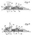
- FIG. 1is a schematic side view showing a cross-country ski boot mounted on a ski by means of a binding device according to the teachings of the invention
- FIG. 2is a side view of the front portion of the binding device of FIG. 1 ;
- FIG. 3is a longitudinal cross-sectional view of the front portion of FIG. 2 ;
- FIG. 4is a top view of the front portion of FIG. 2 ;
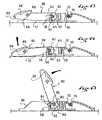
- FIGS. 5 and 6are views similar to that of FIG. 3 , showing the two directions for manipulating the opening mechanism of the device;
- FIG. 7is a schematic partial, longitudinal cross-sectional view of a second embodiment of a binding device according to the invention.
- FIGS. 8 and 9are views to that of FIG. 7 , showing the two directions for manipulating the opening mechanism of the device;
- FIGS. 10 , 11 , and 12are views similar to those of FIGS. 7 , 8 , and 9 , showing a third embodiment of the invention.
- FIGS. 13 , 14 , and 15are views similar to those of FIGS. 7 , 8 , and 9 , showing a fourth embodiment of the invention.
- FIGS. 16 , 17 , and 18are views similar to those of FIGS. 7 , 8 , and 9 , showing a fifth embodiment of the invention.
- FIGS. 19 , 20 , and 21are similar views than those in FIGS. 7 , 8 , and 9 showing a sixth embodiment of the invention.
- binding deviceor binding
- bindingis more particularly adapted to cross-country skiing.
- the first embodiment of a binding 10 shown in FIGS. 1 to 6includes a baseplate 12 , or base, which is adapted to be fixed to a sports article 11 , here a ski, but which could also be directly integrated or made in one-piece with the ski.
- the baseplate 12could also be made of different parts, some or none of these parts possibly being integrated to the sports article/ski 11 .
- the deviceis adapted to carry out the binding of a boot 14 including connecting means in two parts.
- the bootincludes two connecting pins 16 , 18 , which are arranged in the boot sole so as to be flush below the sole. Connecting pins 16 , 18 of this type are described in the patent documents EP-913 102, EP-913 103, and U.S. Pat. No. 6,289,610, the disclosure of U.S. Pat. No. 6,289,610 being herein incorporated by reference thereto in its entirety for this purpose.
- the pinstake the form of two cylindrical rods positioned within the sole but extending across a longitudinal groove, preferably above the lowermost external surface of the sole and extending through a longitudinal median plane of the sole, thereby exposing an intermediate length of each of the pins for engagement with the binding.
- the front pin 16is for example located in the vicinity of the front end of the sole and the rear pin 18 is offset toward the rear by a distance defined to be arranged in the area of, or at the front of a boot area corresponding to, the metatarsophalangeal bending zone of the user's foot.
- connecting zonesis particularly useful in cross-country skiing as it allows, with a boot having a flexible sole, the bending/flexing of the boot to correspond to that of the foot.
- the inventioncould be implemented with connecting members having another geometry or another configuration, for example, non-circular sectional rods, hooks, catching latches, or grooves formed directly in the same material as the sole, etc.
- the front pin 16is adapted to cooperate, in a known manner, with a latching mechanism 19 , or locking mechanism, including a movable jaw 20 , in the form of a hook, and a transverse edge/surface 22 of the baseplate constituting a stationary jaw for the rotational locking of the boot to the sports article.
- a latching mechanism 19or locking mechanism, including a movable jaw 20 , in the form of a hook, and a transverse edge/surface 22 of the baseplate constituting a stationary jaw for the rotational locking of the boot to the sports article.
- the rear pin 18is adapted to be fastened to an elastic return system that is integrated into a guiding rib 24 of the device. As shown in FIG. 1 , the guiding rib projects upward from the ski 11 and is received in a complementary recess in the sole of the boot 14 .
- Such elastic return systemis disclosed, for example, in the documents EP-768 103 and U.S. Pat. No. 6,017,050, commonly owned herewith. The disclosure of U.S. Pat. No. 6,017,050 is herein incorporated by reference thereto in its entirety for this purpose.
- a connecting rod 26or linkage, having a hook-shaped front end 28 (adapted to be fixed to the rear pin 18 ), and a rear end connected to the baseplate 12 so as to be able to longitudinally slide and rotate around a transverse axis.
- An elastic return mechanism(not shown in the drawings herein), such as a spring, applies an elastic force to bring the connecting rod 26 back to the resting position, shown in FIG. 1 . Therefore, when the heel of the boot is raised by pivoting the boot around its front pin 16 , the connecting rod 26 , hooked to the rear pin 18 , can follow the upward and frontward displacement of the rear pin 18 while exerting a return force on the latter that tends to bring the sole of the boot back toward the upper surface of the ski.
- the inventioncan also be implemented for devices including other elastic return mechanisms, for example, including at the front of the binding an elastic buffer against which the front end of the boot is engaged when the heel of the boot is raised.
- the bootcould therefore be provided with only one connecting pin/rod.
- FIGS. 2 to 6more particularly show the locking mechanism 19 of the front pin 16 of the boot.
- FIGS. 3 , 5 , and 6The operating principle of the locking mechanism here is known from the prior art (as, for example, in the bindings marketed by Salomon S.A. under the name “SNS Profil Auto”), and is therefore described herein for information purposes only, although the scope of the present invention encompasses the utilization of other types of locking mechanisms.
- the locking mechanism 19essentially includes a movable piece 30 , or slide, that is longitudinally movable between a rear locking position (shown in FIG. 3 ), and a front unlocking position ( FIGS. 5 and 6 ).
- the slidecan be made from a molded plastic material, for example, and includes an upper hook 32 , or hook-shaped part, curved forwardly and then rearwardly.
- the slidecan include a metallic reinforcement 34 that protects the inner surface of the hook 32 , the inner surface being adapted to form a housing for the pin of the boot.
- the hook 32is positioned opposite the transverse edge 22 of the baseplate 12 so as to demarcate a housing with the latter, transversely open at its two ends, able to receive the pin 16 .
- the pin 16is received in the housing and the slide is in the setback position, the pin is locked and can only rotate around its axis.
- the housingbecomes opens at the top, allowing the pin to exit outside of the housing or to be again inserted into the housing.
- bindings 10which are described below, are provided with self-locking mechanisms.
- the locking mechanismincludes a compression spring 36 supported on the baseplate 12 , on the one hand, and on the slide 30 , on the other hand, to push the slide toward its rearward locking position.
- the hook 32 of the slide and the transverse edge 22include portions of ramps in the form of a V-shaped structure. A user can therefore engage the front pin 16 of his/her boot bearing on the hook ramps and the transverse edge of the baseplate and, by a mere vertical force and due to the ramps, make the hook move forward against the action of the spring 36 .
- the pin 16can engage inside the housing and the spring 36 can trigger the return of the slide 30 toward its locking position in which the hook 32 prevents the pin from withdrawing from the housing.
- a self-locking locking mechanismis advantageous in that it allows the boot to be locked on the binding without any particular action from the user, unlike other mechanisms in which the locking of the boot requires one or several manual operations of the user.
- the bindingincludes a user-manipulable opening system for controlling the opening of the locking mechanism.
- the opening systemis configured and arranged to be independently manipulated, directly or indirectly, according to either of at least two distinct directions of manipulation for controlling the opening mechanism. This is further described below.
- the opening of the locking mechanismrequires the triggering of the longitudinal forward displacement of the slide 30 from its rear locking position to its open front position.
- the opening controlcould require controlling other movements of the movable element (translational motion, rotational motion, or a combination of the two motions), and/or the same type of movement, but in a different direction.
- the opening mechanismis located at the front end of the binding and includes two distinct control members, each manipulable according to one of the at least two directions of manipulation.
- the first control memberis a lever 38 that is articulated by its front articulation end on the baseplate 12 around a transverse axis A 1 .
- the leveris extended by a prehension arm 40 , which, in its resting position shown in FIGS. 2 to 4 , extends substantially horizontally and toward the back above the baseplate 12 .
- the baseplateis provided with recesses 42 on its lateral surfaces that allow rendering the lateral edges of the lever's 38 prehension arm 40 very accessible to the user's hand.
- the second control memberis a slider 44 , the rear end of which is connected to the slide 30 by means of an articulation rod 46 having a transverse axis A 2 .
- the articulation rod 46affixes the slider 44 to the slide 30 in translation.
- the front end of the slider 44is connected to the lever 38 by means of a connecting rod 48 having a transverse axis A 3 .
- the rod 48transversely extends through the front end of the slider 44 and has two transverse end portions, which are received in the slots 50 arranged in parallel flanges 52 of the lever 38 , flanges that vertically and longitudinally extend under the prehension arm 40 .
- Two flanges 52transversely frame the front of the slider 44 , and the two slots 50 are angled about 45 degrees forwardly and downwardly.
- the connecting rod 48connects the slider 44 to the lever 38 by allowing the two elements to have movements that are relative in translation and in rotation.
- the slider 44includes, in its front portion, a head 54 that extends toward the top so as to outwardly project through an opening 56 housed at the center of the prehension arm 40 of the lever 38 .
- the lever 38At rest, such as shown in FIGS. 2 to 4 , the lever 38 is supported in a low position on the baseplate, whereas the slider 44 , under the effect of spring 36 and via the slide 30 , is in a high setback position in which the connecting rod 48 that is connected to the slider 44 , is received substantially at the high rear end of the angled slots 50 of the lever 38 .
- the usercan trigger the opening of the locking mechanism with either of two distinct actions.
- the usercan exert a substantially vertical pressure from the top to the bottom on the head 54 of the slider 44 , for example, with his/her hand or with the end of a ski pole (the use of a pole enabling him/her to open the device without having to bend down).
- the connecting rod 48which is connected to the slider 44 slides in the slots 50 of the lever 38 .
- the lever 38then remains immobile since it is in abutment on the baseplate 12 .
- the connecting rod 48triggers a transformation of the vertical force exerted by the user in a combined movement of the slider 44 (like in a system with a cam), this movement being the combination of a frontward longitudinal translation with a rotation around axis A 2 (in the counter-clockwise direction in the drawings). Because the slider 44 and the slide 30 are connected by a pivot connection, the longitudinal translation component of the slider 44 movement is directly transmitted to the slide 30 , which is thus controlled toward its front position for opening. As soon as the user releases force on the head 54 of the slider 44 , the spring 36 brings the slider 44 back to its resting position, and, at the same time, the slide 30 toward its rear locking position.
- the usercan grab the prehension arm 40 of the lever 38 and lift it upwardly, thereby triggering a rotation of the lever around the axis A 1 (in the counter-clockwise direction in the drawings).
- the slots 50 of the flanges 52 of the lever 38drive with them the connecting rod 48 that is affixed to the slider 44 .
- the slider 44is thus driven forwardly, taking with it the slide 30 toward its front unlocking position.
- the spring 36brings the slide 30 and the slider 44 back toward their resting positions, and the latter brings, by means of the connecting rod 48 , the lever 38 back toward its initial position.
- the first wayis by means of a pressure exerted substantially downward.
- the second wayis by means of a substantially upwardly directed traction force.
- the userwill therefore be able to choose anytime the most practical manner for him/her to control the opening of the mechanism.
- Each of the two control members, i.e., the slider 44 and the lever 38are external to the article of footwear, i.e., the boot in this embodiment, and accessible externally of the article of footwear.
- the slider 44when downwardly manipulated, directly controls the opening of the locking mechanism, and the lever 38 , when upwardly manipulated, controls the opening of the mechanism by means of the slider 44 , thus indirectly.
- the two control membersmove according to different types of movements.
- the locking mechanism and its opening systemshare a single elastic return member, that is, the spring 36 .
- the second embodiment of the invention shown in FIGS. 7 to 9also includes two distinct members for controlling the opening, but, unlike the first embodiment, these two members, when manipulated by the user, move with the same type of movement, that is, a rotational movement.
- the slide 30 of the locking mechanismincludes a forward extension ended with a raised nose 58 including a support surface 60 that is substantially vertical and turned rearward.
- the opening systemincludes a lever 38 articulated on the baseplate 12 about a transverse axis A 4 .
- a rocking member 62or rocker, is articulated on the lever and/or on the baseplate about the same axis A 4 . It could also be articulated on an axis offset with respect to the axis A 4 .
- the rocker 62includes two substantially perpendicular arms, which extend substantially radially from the axis A 4 .
- An upper arm 66extends rearwardly along a substantially horizontal direction and has an upper surface 68 , generally convex, although not limited to such contour, on which a user can exert a downward vertical pressure, for example with a ski pole.
- a lower arm 70extends substantially downward and includes a control finger 72 that is forwardly supported against the support surface 60 of the raised nose 58 of the slide 30 .
- an abutment 74is provided to limit the extent of the rotation of the rocker 62 in one of the two directions.
- the lever 38carries the abutment.
- the lever 38When the front end of the lever 38 is grabbed by the user and raised upwardly (c.f. FIG. 9 ), such motion triggers a rotation of the lever 38 about the axis A 4 ; but it also triggers, by means of the abutment 74 , the rotation of the rocker 62 , which, as shown above, triggers the forward displacement of the slide 30 .
- the lever 38includes a member 76 , shown as pivoted to the lever 38 , that can be raised upwardly, which facilitates the grasping and manipulation of the lever.
- the member 76is optional; it could be replaced by a flexible cord or by a specific geometry of the lever, or it could even be omitted, the member 76 not being an independent control member for the lever 38 .
- the opening systemincludes two control members: the rocker 62 that directly controls the opening of the locking mechanism, independently from any displacement of the second control member, and the lever 38 that indirectly controls the mechanism by means of the rocker 62 .
- FIGS. 10 to 12A third embodiment of the invention is shown in FIGS. 10 to 12 , in which the system for opening the locking mechanism includes only one control member.
- the systemis identical to the preceding one, except that the lever and the rocker are made as one and only piece: the rocker 78 articulated on the baseplate 12 about the axis A 4 , and which includes an upper support surface 68 arranged rearward from the axis A 4 , on the one hand, and front prehension arrangement (i.e., the member 76 ) arranged forward from the axis A 4 , on the other hand, and so as to trigger the same tipping move of the rocker 78 , the user can choose to downwardly push on the rear surface 68 , or to upwardly pull the front prehension member 76 .
- the rockerrevolves about the axis A 4 and, by means of a control finger 72 , controls the forward translation of the slide 30 .
- the fourth and fifth embodiments of the invention shown, respectively, in FIGS. 13-15 and in 16 - 18also include a single control member for opening the locking mechanism, which is, according to the invention, capable of being manipulated independently according to two distinct directions of manipulation for controlling the mechanism opening.
- the two directions of manipulationcorrespond to movements of the locking member that are not of the same type.
- the control memberis a lever 80 connected to the baseplate 12 by means of a connecting rod 82 .
- This connecting rod 82having a transverse axis A 5 is affixed to the rear end of the lever 80 and is received in a slot 84 of the baseplate 12 (or in several parallel slots).
- the slot 84is substantially rectilinear and is extended along the longitudinal direction so that the connection between the lever 80 and the baseplate 12 allows the lever to rotate about the axis A 5 and to longitudinally translate.
- the lever 80is supported at its front end on an inclined surface 86 of the baseplate.
- the inclined surface 86is a surface facing both upwardly and forwardly, the shape of which is therefore downwardly and forwardly inclined.
- the lever 80has, for example, a pin or a roller 88 that is in contact with the inclined surface 86 .
- the lever 80has, at its front end, an upper support surface 68 on which the user can exert a substantially vertical, downward force, and lateral edges 90 providing a surface that can facilitate prehension and manipulation by the user, thereby enabling the user to effectively grab and manipulate the front end of the lever 80 so as to raise it upwardly.
- the lever 80is thusly connected to the baseplate 12 by means of a connection having at least two degrees of freedom.
- the leverincludes at its rear end a cam 92 , which is arranged about the axis A 5 and is adapted to be supported against the rear support surface 60 of the raised nose 58 arranged at the front of the slide 30 .
- the eccentricity of the cam 92is such that when the user triggers the lifting of the lever 80 by pulling its front end upwardly, the lever 80 then turns about the axis A 5 of the connecting rod 82 , the surface of the cam 92 pushes the slide 30 forwardly (c.f. FIG. 15 ).
- the lever 80cannot translate rearwardly with respect to baseplate 12 because the connecting rod 82 is blocked toward the rear against the rear end of the slot 84 . The movement of the lever is therefore a true rotation.
- the fifth embodiment shown in FIGS. 16 to 18differs from the previous one only by the fact that the rod 82 is in contact with the rear surface 60 of the raised nose 58 of the slide 30 , and by the fact that the lever includes a rear surface that forms a cam 94 adapted to be supported against the corresponding contact surface 96 of the baseplate 12 .
- the cam 94triggers, as a function of the lifting angle, a forward, horizontal translation of the rear end of the lever. This translation is then directly passed on the slide 30 by the connecting rod 82 .
- the movement of the leveris a combination of a rotation and a translation movement.
- the opening systemincludes a single control member, which is a sliding member 100 , or sliding block, movably mounted in upward translation relative to the baseplate 12 .
- the member 100is provided with a central locking position ( FIG. 19 ) and two opening positions, high and low (see FIGS. 20 and 21 ).
- the member 100is connected to the slide 30 by means of a connecting element 102 mounted in the baseplate 12 so as to be able to slide longitudinally only.
- the front end of the connecting element 102includes a transverse pin 104 , which is received in a slot 106 formed in the sliding member 100 .
- the slot 106includes two arms: an upper arm 106 a upwardly and forwardly oriented, and a lower arm 106 b , downwardly and forwardly oriented. In a side view such as shown in the drawings, the slot 106 therefore has a V-shaped profile, the point of which is longitudinally directed toward the rear. When the sliding member 100 is in the central position, the pin 104 of the connecting element is engaged in the slot 106 at the intersection of the two arms, at the V point.
- the exemplary embodiment illustratedhas been provided, as an example, an upper support surface 68 and a retractable pivoted pull rod 76 .
- Each of the exemplary embodiments of the binding, described herein,has a construction that is particularly ergonomic, facilitating manipulation by the user under any circumstance.
- the ease of useis favored while having the possibility of adapting the geometry of the control member to the better, or preferred, of two modes of manipulation.
- the control surfacescan be better specified in order, for example, to facilitate the manual prehension or support with an accessory.
- Onewill also be able to easily design control members having features such as lever arms adapted to the force that the user can exert according to the corresponding direction of manipulation, this, in order to control with an equivalent ease, the locking mechanism according to the two directions of manipulation.
Landscapes
- Footwear And Its Accessory, Manufacturing Method And Apparatuses (AREA)
- Seal Device For Vehicle (AREA)
- Mechanical Control Devices (AREA)
- Sheet Holders (AREA)
- Paper (AREA)
- Basic Packing Technique (AREA)
- Preparation Of Compounds By Using Micro-Organisms (AREA)
- Iron Core Of Rotating Electric Machines (AREA)
- Pressure Welding/Diffusion-Bonding (AREA)
Abstract
Description
Claims (40)
Applications Claiming Priority (3)
| Application Number | Priority Date | Filing Date | Title |
|---|---|---|---|
| FR0502235AFR2882658B1 (en) | 2005-03-07 | 2005-03-07 | DOUBLE CONTROL FIXING DEVICE |
| FR05.02235 | 2005-03-07 | ||
| FR0502235 | 2005-03-07 |
Publications (2)
| Publication Number | Publication Date |
|---|---|
| US20060197312A1 US20060197312A1 (en) | 2006-09-07 |
| US7832754B2true US7832754B2 (en) | 2010-11-16 |
Family
ID=35170051
Family Applications (1)
| Application Number | Title | Priority Date | Filing Date |
|---|---|---|---|
| US11/367,355Expired - Fee RelatedUS7832754B2 (en) | 2005-03-07 | 2006-03-06 | Dual-control binding device |
Country Status (7)
| Country | Link |
|---|---|
| US (1) | US7832754B2 (en) |
| EP (1) | EP1702658B1 (en) |
| AT (1) | ATE415189T1 (en) |
| DE (1) | DE602006003786D1 (en) |
| FR (1) | FR2882658B1 (en) |
| NO (1) | NO330832B1 (en) |
| RU (1) | RU2394621C2 (en) |
Cited By (20)
| Publication number | Priority date | Publication date | Assignee | Title |
|---|---|---|---|---|
| US20100102522A1 (en)* | 2008-10-23 | 2010-04-29 | Kloster Bryce M | Splitboard binding apparatus |
| US20100109290A1 (en)* | 2008-11-03 | 2010-05-06 | Atomic Austria Gmbh | Ski binding with a positioning and fixing mechanism for its binding piece bodies |
| US20150209650A1 (en)* | 2014-01-24 | 2015-07-30 | Technische Universitat Munchen | Ski binding with forefoot fixing module |
| US9149711B1 (en) | 2014-11-14 | 2015-10-06 | The Burton Corporation | Snowboard binding and boot |
| US9220970B1 (en) | 2014-11-14 | 2015-12-29 | The Burton Corporation | Snowboard binding and boot |
| US9238168B2 (en) | 2012-02-10 | 2016-01-19 | Bryce M. Kloster | Splitboard joining device |
| US9266010B2 (en) | 2012-06-12 | 2016-02-23 | Tyler G. Kloster | Splitboard binding with adjustable leverage devices |
| US9566498B2 (en) | 2013-09-20 | 2017-02-14 | Rottafella As | Ski binding for touring or cross-country skiing |
| US9604122B2 (en) | 2015-04-27 | 2017-03-28 | Bryce M. Kloster | Splitboard joining device |
| USD820933S1 (en) | 2016-05-04 | 2018-06-19 | Salomon S.A.S. | Ski binding |
| USD820932S1 (en) | 2016-05-04 | 2018-06-19 | Salomon S.A.S. | Ski binding |
| US10029165B2 (en) | 2015-04-27 | 2018-07-24 | Bryce M. Kloster | Splitboard joining device |
| US10179272B2 (en) | 2014-11-14 | 2019-01-15 | The Burton Corporation | Snowboard binding and boot |
| US11117042B2 (en) | 2019-05-03 | 2021-09-14 | Bryce M. Kloster | Splitboard binding |
| USD1007110S1 (en) | 2022-03-23 | 2023-12-12 | Mountain Origins Design LLC | Footwear |
| USD1007826S1 (en) | 2022-03-23 | 2023-12-19 | Mountain Origins Design LLC | Footwear |
| USD1007825S1 (en) | 2022-03-23 | 2023-12-19 | Mountain Origins Design LLC | Footwear |
| USD1008611S1 (en) | 2022-03-23 | 2023-12-26 | Mountain Origins Design LLC | Footwear |
| US11938394B2 (en) | 2021-02-22 | 2024-03-26 | Bryce M. Kloster | Splitboard joining device |
| USD1033862S1 (en) | 2022-03-23 | 2024-07-09 | Mountain Origins Design LLC | Footwear |
Families Citing this family (8)
| Publication number | Priority date | Publication date | Assignee | Title |
|---|---|---|---|---|
| FR2910337B1 (en)* | 2006-12-20 | 2009-06-05 | Salomon Sa | ARTICLE COMPRISING A MOBILE BUTTON BETWEEN AT LEAST TWO POSITIONS |
| FR2929531B3 (en)* | 2008-04-08 | 2010-08-13 | Salomon Sas | ASSEMBLY COMPRISING A SLIDING BOARD AND A RETAINING DEVICE FOR A FOOTWEAR ARTICLE. |
| NO20101289A1 (en)* | 2010-09-15 | 2012-03-16 | Rottefella As | Cross-country bonding, as well as a method for assembling said cross-country bonding |
| FR2967584B1 (en)* | 2010-11-19 | 2013-04-26 | Salomon Sas | RETENTION DEVICE COMPRISING A REVERSIBLE LOCKING MECHANISM OF AN ANCHORING ELEMENT OF A SHOE |
| CN105593028B (en)* | 2013-09-19 | 2017-07-28 | 株式会社喜利 | binding tool |
| RU197293U1 (en)* | 2020-02-03 | 2020-04-20 | Роман Владимирович Шамов | The locking mechanism with the overlapping groove in which the boot pin is in working condition |
| WO2022265531A1 (en)* | 2021-06-18 | 2022-12-22 | Дмитрий Михайлович ЛИ | Snowboard binding with emergency release |
| CN113519964B (en)* | 2021-07-20 | 2022-10-11 | 中国人民解放军陆军军医大学第二附属医院 | Tumble early warning system based on neural network signals |
Citations (35)
| Publication number | Priority date | Publication date | Assignee | Title |
|---|---|---|---|---|
| US3810644A (en)* | 1971-07-30 | 1974-05-14 | J Beyl | Ski binding |
| US3909023A (en)* | 1973-07-16 | 1975-09-30 | Wunder Kg Heinrich | Safety ski binding |
| US4153271A (en)* | 1976-01-16 | 1979-05-08 | Kastle (Schweiz) Ag | Binding for cross-country skiing |
| US4214773A (en)* | 1977-11-18 | 1980-07-29 | Tmc Corporation | Heel holder for release ski binding |
| US4309044A (en)* | 1977-12-03 | 1982-01-05 | Vereinigte Baubeschlagfabriken Gretsch & Co., Gmbh | Cross-country ski binding |
| US4457534A (en)* | 1980-09-05 | 1984-07-03 | Marker-Patentverwertungsgesellschaft Mbh. | Heelholder for safety ski binding |
| US4611414A (en)* | 1982-07-19 | 1986-09-16 | Vogel Raimund W | Skiboot |
| FR2638974A1 (en) | 1988-08-16 | 1990-05-18 | Salomon Sa | ATTACHMENT OF HINGED TYPE BACKGROUND SKI |
| FR2645764A1 (en) | 1989-04-12 | 1990-10-19 | Salomon Sa | Binding for a cross-country ski |
| US5026087A (en)* | 1988-07-27 | 1991-06-25 | Wulf Elmer B | Ski boot and ski boot-binding |
| US5224730A (en)* | 1990-04-06 | 1993-07-06 | Salomon S.A. | Cross country ski binding |
| EP0551899A1 (en) | 1992-01-16 | 1993-07-21 | Rottefella As | Cross-country or touring skibinding for cross-country ski shoes |
| EP0679415A1 (en) | 1994-04-29 | 1995-11-02 | Salomon S.A. | Binding for a skiing device |
| FR2733159A1 (en) | 1995-04-21 | 1996-10-25 | Vigny Serge Etienne | SAFETY BINDING FOR TELEMARK SKIING, NORTHERN HIKING AND SKI JUMP |
| FR2738158A1 (en) | 1995-09-06 | 1997-03-07 | Salomon Sa | Binding for fixing sport article to footwear, e.g. boot to cross country ski |
| US5609347A (en)* | 1995-05-17 | 1997-03-11 | Dressel; Donald | Snowboard bindings with release apparatus |
| EP0768103A1 (en) | 1995-10-16 | 1997-04-16 | Salomon S.A. | Boot-binding combination for a skiing device |
| FR2742060A1 (en) | 1995-12-08 | 1997-06-13 | Salomon Sa | DEVICE FOR ATTACHING A SHOE TO A SPORTS ARTICLE |
| US5669622A (en)* | 1995-02-08 | 1997-09-23 | Miller; Michael E. | Ski binding |
| EP0913103A1 (en) | 1997-10-29 | 1999-05-06 | Salomon S.A. | Sole for sportsshoe |
| EP0913102A1 (en) | 1997-10-29 | 1999-05-06 | Salomon S.A. | Sole for sportsshoe |
| FR2776200A1 (en) | 1998-03-19 | 1999-09-24 | Salomon Sa | Sports boot fastening e.g. for ski or skate |
| WO2000004965A1 (en) | 1998-07-22 | 2000-02-03 | Rottefella As | Ski binding, especially for cross-country skis |
| US6027135A (en) | 1996-06-14 | 2000-02-22 | Rottefella As | Cross-country or touring ski binding |
| US6279924B1 (en)* | 1997-09-30 | 2001-08-28 | Powder Design Pty Ltd. | Snowboard safety release binding |
| WO2001093963A1 (en) | 2000-06-08 | 2001-12-13 | Rottefella As | System consisting of ski binding and ski boot |
| US6390493B1 (en)* | 1995-02-02 | 2002-05-21 | Rottefella A/S | Combination of a ski binding and of a boot adapted thereto |
| FR2834473A1 (en) | 2002-01-04 | 2003-07-11 | Salomon Sa | CROSS-COUNTRY SKI BINDING |
| WO2003084620A1 (en) | 2002-04-11 | 2003-10-16 | Fischer Gesellschaft M.B.H. | Ski binding, in particular for cross-country skiing |
| FR2843310A1 (en) | 2002-08-08 | 2004-02-13 | Salomon Sa | FRONT LOADING FIXING DEVICE |
| US20040056449A1 (en) | 2001-02-02 | 2004-03-25 | Salomon S.A. | Binding device with front unfastening |
| FR2853253A1 (en) | 2003-04-03 | 2004-10-08 | Salomon Sa | FIXING WITH A TWO-PART LINK |
| FR2856312A1 (en) | 2003-06-18 | 2004-12-24 | Salomon Sa | FIXING DEVICE WITH PIVOTING ARM |
| DE102004018296A1 (en) | 2004-04-15 | 2005-02-10 | Rottefella ASA | Binding for cross country skis has projection on sole side between engagement element and front sole end to bear against stop so that boot is engaged with binding but can tilt about cross axis |
| US7219917B2 (en)* | 2004-06-30 | 2007-05-22 | Black Diamond Equipment, Ltd. | Cartridge radius surface |
Family Cites Families (2)
| Publication number | Priority date | Publication date | Assignee | Title |
|---|---|---|---|---|
| EP0428140B1 (en)* | 1989-11-14 | 1995-03-29 | Shimano Inc. | Connecting structure between bicycle pedal and cleat, bicycle pedal and cleat |
| AT411018B (en)* | 2001-04-11 | 2003-09-25 | Fischer Gmbh | SKI BINDING FOR CROSS-COUNTRY SKIING AND TOURING SKIING |
- 2005
- 2005-03-07FRFR0502235Apatent/FR2882658B1/ennot_activeExpired - Fee Related
- 2006
- 2006-03-02ATAT06004072Tpatent/ATE415189T1/enactive
- 2006-03-02EPEP06004072Apatent/EP1702658B1/ennot_activeNot-in-force
- 2006-03-02DEDE602006003786Tpatent/DE602006003786D1/enactiveActive
- 2006-03-06RURU2006106878/12Apatent/RU2394621C2/ennot_activeIP Right Cessation
- 2006-03-06USUS11/367,355patent/US7832754B2/ennot_activeExpired - Fee Related
- 2006-03-07NONO20061096Apatent/NO330832B1/ennot_activeIP Right Cessation
Patent Citations (50)
| Publication number | Priority date | Publication date | Assignee | Title |
|---|---|---|---|---|
| US3810644A (en)* | 1971-07-30 | 1974-05-14 | J Beyl | Ski binding |
| US3909023A (en)* | 1973-07-16 | 1975-09-30 | Wunder Kg Heinrich | Safety ski binding |
| US4153271A (en)* | 1976-01-16 | 1979-05-08 | Kastle (Schweiz) Ag | Binding for cross-country skiing |
| US4214773A (en)* | 1977-11-18 | 1980-07-29 | Tmc Corporation | Heel holder for release ski binding |
| US4309044A (en)* | 1977-12-03 | 1982-01-05 | Vereinigte Baubeschlagfabriken Gretsch & Co., Gmbh | Cross-country ski binding |
| US4457534A (en)* | 1980-09-05 | 1984-07-03 | Marker-Patentverwertungsgesellschaft Mbh. | Heelholder for safety ski binding |
| US4611414A (en)* | 1982-07-19 | 1986-09-16 | Vogel Raimund W | Skiboot |
| US5026087A (en)* | 1988-07-27 | 1991-06-25 | Wulf Elmer B | Ski boot and ski boot-binding |
| FR2638974A1 (en) | 1988-08-16 | 1990-05-18 | Salomon Sa | ATTACHMENT OF HINGED TYPE BACKGROUND SKI |
| US5052710A (en) | 1988-08-16 | 1991-10-01 | Salomon S.A. | Hinge type cross-country ski binding |
| FR2645764A1 (en) | 1989-04-12 | 1990-10-19 | Salomon Sa | Binding for a cross-country ski |
| US5092620A (en) | 1989-04-12 | 1992-03-03 | Salomon S.A. | Binding for cross-country ski boot |
| US5224730A (en)* | 1990-04-06 | 1993-07-06 | Salomon S.A. | Cross country ski binding |
| US5338053A (en) | 1992-01-16 | 1994-08-16 | Rottefella A/S | Cross-country or touring ski binding for cross-country ski boots |
| EP0551899A1 (en) | 1992-01-16 | 1993-07-21 | Rottefella As | Cross-country or touring skibinding for cross-country ski shoes |
| US5671941A (en) | 1994-04-29 | 1997-09-30 | Salomon S.A. | Apparatus for attaching a shoe to a gliding element |
| EP0679415A1 (en) | 1994-04-29 | 1995-11-02 | Salomon S.A. | Binding for a skiing device |
| US6390493B1 (en)* | 1995-02-02 | 2002-05-21 | Rottefella A/S | Combination of a ski binding and of a boot adapted thereto |
| US5669622A (en)* | 1995-02-08 | 1997-09-23 | Miller; Michael E. | Ski binding |
| FR2733159A1 (en) | 1995-04-21 | 1996-10-25 | Vigny Serge Etienne | SAFETY BINDING FOR TELEMARK SKIING, NORTHERN HIKING AND SKI JUMP |
| US5957478A (en) | 1995-04-21 | 1999-09-28 | Salomon S.A. | Release binding for telemark skiing, back country skiing, and ski jumping |
| US5609347A (en)* | 1995-05-17 | 1997-03-11 | Dressel; Donald | Snowboard bindings with release apparatus |
| FR2738158A1 (en) | 1995-09-06 | 1997-03-07 | Salomon Sa | Binding for fixing sport article to footwear, e.g. boot to cross country ski |
| US5794963A (en) | 1995-09-06 | 1998-08-18 | Salomon S.A. | Binding device and a binding device/boot assembly |
| EP0768103A1 (en) | 1995-10-16 | 1997-04-16 | Salomon S.A. | Boot-binding combination for a skiing device |
| US6017050A (en) | 1995-10-16 | 2000-01-25 | Salomon S.A. | Assembly for binding a boot to a gliding element |
| FR2742060A1 (en) | 1995-12-08 | 1997-06-13 | Salomon Sa | DEVICE FOR ATTACHING A SHOE TO A SPORTS ARTICLE |
| EP0904139B1 (en) | 1996-06-14 | 2003-02-19 | Rottefella A/S | Cross-country or touring ski binding |
| US6027135A (en) | 1996-06-14 | 2000-02-22 | Rottefella As | Cross-country or touring ski binding |
| US6279924B1 (en)* | 1997-09-30 | 2001-08-28 | Powder Design Pty Ltd. | Snowboard safety release binding |
| EP0913103A1 (en) | 1997-10-29 | 1999-05-06 | Salomon S.A. | Sole for sportsshoe |
| US6289610B1 (en) | 1997-10-29 | 2001-09-18 | Salomon S.A. | Sole for a sport boot and a sport boot including such sole |
| EP0913102A1 (en) | 1997-10-29 | 1999-05-06 | Salomon S.A. | Sole for sportsshoe |
| US6435537B2 (en) | 1998-03-19 | 2002-08-20 | Salomon S.A. | Device for coupling a shoe with a sports gear |
| FR2776200A1 (en) | 1998-03-19 | 1999-09-24 | Salomon Sa | Sports boot fastening e.g. for ski or skate |
| US6644683B1 (en) | 1998-07-22 | 2003-11-11 | Rottefella As | Ski binding, especially for cross-country skis |
| WO2000004965A1 (en) | 1998-07-22 | 2000-02-03 | Rottefella As | Ski binding, especially for cross-country skis |
| WO2001093963A1 (en) | 2000-06-08 | 2001-12-13 | Rottefella As | System consisting of ski binding and ski boot |
| US6986526B2 (en) | 2000-06-08 | 2006-01-17 | Rottefella A/S | Arrangement comprising a ski binding and a ski boot |
| US20040056449A1 (en) | 2001-02-02 | 2004-03-25 | Salomon S.A. | Binding device with front unfastening |
| FR2834473A1 (en) | 2002-01-04 | 2003-07-11 | Salomon Sa | CROSS-COUNTRY SKI BINDING |
| US6811177B2 (en) | 2002-01-04 | 2004-11-02 | Salomon S.A. | Binding for a cross-country ski |
| EP1492598B1 (en) | 2002-04-11 | 2005-08-31 | Fischer Gesellschaft m.b.H. | Ski binding, in particular for cross-country skiing |
| WO2003084620A1 (en) | 2002-04-11 | 2003-10-16 | Fischer Gesellschaft M.B.H. | Ski binding, in particular for cross-country skiing |
| FR2843310A1 (en) | 2002-08-08 | 2004-02-13 | Salomon Sa | FRONT LOADING FIXING DEVICE |
| FR2853253A1 (en) | 2003-04-03 | 2004-10-08 | Salomon Sa | FIXING WITH A TWO-PART LINK |
| US20040262886A1 (en) | 2003-06-18 | 2004-12-30 | Salomon S.A. | Binding device having a pivotable arm |
| FR2856312A1 (en) | 2003-06-18 | 2004-12-24 | Salomon Sa | FIXING DEVICE WITH PIVOTING ARM |
| DE102004018296A1 (en) | 2004-04-15 | 2005-02-10 | Rottefella ASA | Binding for cross country skis has projection on sole side between engagement element and front sole end to bear against stop so that boot is engaged with binding but can tilt about cross axis |
| US7219917B2 (en)* | 2004-06-30 | 2007-05-22 | Black Diamond Equipment, Ltd. | Cartridge radius surface |
Cited By (32)
| Publication number | Priority date | Publication date | Assignee | Title |
|---|---|---|---|---|
| US8469372B2 (en) | 2008-10-23 | 2013-06-25 | Bryce M. Kloster | Splitboard binding apparatus |
| US8733783B2 (en) | 2008-10-23 | 2014-05-27 | Bryce M. Kloster | Splitboard binding apparatus |
| US9138628B2 (en) | 2008-10-23 | 2015-09-22 | Bryce M. Kloster | Splitboard binding apparatus |
| US9937407B2 (en) | 2008-10-23 | 2018-04-10 | Bryce M. Kloster | Splitboard binding |
| US20100102522A1 (en)* | 2008-10-23 | 2010-04-29 | Kloster Bryce M | Splitboard binding apparatus |
| US20100109290A1 (en)* | 2008-11-03 | 2010-05-06 | Atomic Austria Gmbh | Ski binding with a positioning and fixing mechanism for its binding piece bodies |
| US7988180B2 (en)* | 2008-11-03 | 2011-08-02 | Atomic Austria Gmbh | Ski binding with a positioning and fixing mechanism for its binding piece bodies |
| US9238168B2 (en) | 2012-02-10 | 2016-01-19 | Bryce M. Kloster | Splitboard joining device |
| US9266010B2 (en) | 2012-06-12 | 2016-02-23 | Tyler G. Kloster | Splitboard binding with adjustable leverage devices |
| US10279239B2 (en) | 2012-06-12 | 2019-05-07 | Tyler G. Kloster | Leverage devices for snow touring boot |
| US9566498B2 (en) | 2013-09-20 | 2017-02-14 | Rottafella As | Ski binding for touring or cross-country skiing |
| US9452343B2 (en)* | 2014-01-24 | 2016-09-27 | Technische Universitat Munchen | SKI binding with forefoot fixing module |
| US20150209650A1 (en)* | 2014-01-24 | 2015-07-30 | Technische Universitat Munchen | Ski binding with forefoot fixing module |
| US10179272B2 (en) | 2014-11-14 | 2019-01-15 | The Burton Corporation | Snowboard binding and boot |
| US9220970B1 (en) | 2014-11-14 | 2015-12-29 | The Burton Corporation | Snowboard binding and boot |
| US10702762B2 (en) | 2014-11-14 | 2020-07-07 | The Burton Corporation | Snowboard binding and boot |
| US9149711B1 (en) | 2014-11-14 | 2015-10-06 | The Burton Corporation | Snowboard binding and boot |
| US10898785B2 (en) | 2015-04-27 | 2021-01-26 | Bryce M. Kloster | Splitboard joining device |
| US9795861B1 (en) | 2015-04-27 | 2017-10-24 | Bryce M. Kloster | Splitboard joining device |
| US10112103B2 (en) | 2015-04-27 | 2018-10-30 | Bryce M. Kloster | Splitboard joining device |
| US9604122B2 (en) | 2015-04-27 | 2017-03-28 | Bryce M. Kloster | Splitboard joining device |
| US10029165B2 (en) | 2015-04-27 | 2018-07-24 | Bryce M. Kloster | Splitboard joining device |
| US10343049B2 (en) | 2015-04-27 | 2019-07-09 | Bryce M. Kloster | Splitboard joining device |
| USD820933S1 (en) | 2016-05-04 | 2018-06-19 | Salomon S.A.S. | Ski binding |
| USD820932S1 (en) | 2016-05-04 | 2018-06-19 | Salomon S.A.S. | Ski binding |
| US11117042B2 (en) | 2019-05-03 | 2021-09-14 | Bryce M. Kloster | Splitboard binding |
| US11938394B2 (en) | 2021-02-22 | 2024-03-26 | Bryce M. Kloster | Splitboard joining device |
| USD1007110S1 (en) | 2022-03-23 | 2023-12-12 | Mountain Origins Design LLC | Footwear |
| USD1007826S1 (en) | 2022-03-23 | 2023-12-19 | Mountain Origins Design LLC | Footwear |
| USD1007825S1 (en) | 2022-03-23 | 2023-12-19 | Mountain Origins Design LLC | Footwear |
| USD1008611S1 (en) | 2022-03-23 | 2023-12-26 | Mountain Origins Design LLC | Footwear |
| USD1033862S1 (en) | 2022-03-23 | 2024-07-09 | Mountain Origins Design LLC | Footwear |
Also Published As
| Publication number | Publication date |
|---|---|
| RU2006106878A (en) | 2007-09-27 |
| FR2882658A1 (en) | 2006-09-08 |
| EP1702658A1 (en) | 2006-09-20 |
| FR2882658B1 (en) | 2007-05-04 |
| US20060197312A1 (en) | 2006-09-07 |
| DE602006003786D1 (en) | 2009-01-08 |
| NO330832B1 (en) | 2011-07-25 |
| EP1702658B1 (en) | 2008-11-26 |
| ATE415189T1 (en) | 2008-12-15 |
| RU2394621C2 (en) | 2010-07-20 |
| NO20061096L (en) | 2006-09-07 |
Similar Documents
| Publication | Publication Date | Title |
|---|---|---|
| US7832754B2 (en) | Dual-control binding device | |
| US7111865B2 (en) | Binding device having a pivotable arm | |
| US6964428B2 (en) | Device for binding a boot to a sports article | |
| US4108467A (en) | Ski binding | |
| US6182999B1 (en) | Retention apparatus for a boot on a gliding board | |
| EP1907078B1 (en) | Toe-piece for ski bindings | |
| JPH05184404A (en) | Ski boots provided with body fixing device | |
| US7264263B2 (en) | Ski binding | |
| RU2004131221A (en) | FOOTWEAR FOOTWEAR | |
| US7644947B2 (en) | Device for binding a boot to a sports article having a separate elastic return system | |
| EP2281614B1 (en) | Heel piece with two-armed front fork engageable with pins on a boot | |
| US20140013629A1 (en) | Ski/walk mechanism | |
| WO2012045374A1 (en) | Ski binding | |
| US10946265B2 (en) | Holding element for a ski boot with a tiltable fitting pedal | |
| US20130307252A1 (en) | Ski binding with brake | |
| US3992037A (en) | Ski binding | |
| US7909352B2 (en) | Article including a button which is movable between at least two positions | |
| JPH05184403A (en) | Ski boots provided with device for fixing central part of its body part | |
| US20180185737A1 (en) | Stop for shoe binding device | |
| US6390494B2 (en) | Cross-country ski binding | |
| WO2014064657A1 (en) | Ski boot | |
| US20120126510A1 (en) | Retaining device including a mechanism for reversibly locking a boot anchoring element | |
| JPS5852666B2 (en) | cross country ski bindings | |
| US4657278A (en) | Step-in electronic safety ski binding | |
| US4607859A (en) | Safety ski binding |
Legal Events
| Date | Code | Title | Description |
|---|---|---|---|
| AS | Assignment | Owner name:SALOMON S.A., FRANCE Free format text:ASSIGNMENT OF ASSIGNORS INTEREST;ASSIGNORS:GIRARD, FRANCOIS;YELOVINA, EDDY;REEL/FRAME:017602/0835 Effective date:20060502 | |
| AS | Assignment | Owner name:SALOMON S.A.S.,FRANCE Free format text:CHANGE OF NAME;ASSIGNOR:SALOMON S.A.;REEL/FRAME:024563/0157 Effective date:20100202 Owner name:SALOMON S.A.S., FRANCE Free format text:CHANGE OF NAME;ASSIGNOR:SALOMON S.A.;REEL/FRAME:024563/0157 Effective date:20100202 | |
| FPAY | Fee payment | Year of fee payment:4 | |
| FEPP | Fee payment procedure | Free format text:MAINTENANCE FEE REMINDER MAILED (ORIGINAL EVENT CODE: REM.) | |
| LAPS | Lapse for failure to pay maintenance fees | Free format text:PATENT EXPIRED FOR FAILURE TO PAY MAINTENANCE FEES (ORIGINAL EVENT CODE: EXP.); ENTITY STATUS OF PATENT OWNER: LARGE ENTITY | |
| STCH | Information on status: patent discontinuation | Free format text:PATENT EXPIRED DUE TO NONPAYMENT OF MAINTENANCE FEES UNDER 37 CFR 1.362 | |
| FP | Lapsed due to failure to pay maintenance fee | Effective date:20181116 |