US7831217B2 - Method and apparatus to provide digital signaling without internal modification of analog FM transceiver - Google Patents
Method and apparatus to provide digital signaling without internal modification of analog FM transceiverDownload PDFInfo
- Publication number
- US7831217B2 US7831217B2US11/870,305US87030507AUS7831217B2US 7831217 B2US7831217 B2US 7831217B2US 87030507 AUS87030507 AUS 87030507AUS 7831217 B2US7831217 B2US 7831217B2
- Authority
- US
- United States
- Prior art keywords
- switch
- emergency
- digital
- push
- signal
- Prior art date
- Legal status (The legal status is an assumption and is not a legal conclusion. Google has not performed a legal analysis and makes no representation as to the accuracy of the status listed.)
- Active, expires
Links
- 230000011664signalingEffects0.000titleclaimsdescription48
- 238000000034methodMethods0.000titleclaimsdescription29
- 230000004048modificationEffects0.000titledescription7
- 238000012986modificationMethods0.000titledescription7
- 230000005236sound signalEffects0.000claimsabstractdescription15
- 230000005540biological transmissionEffects0.000claimsdescription11
- 230000008878couplingEffects0.000claimsdescription3
- 238000010168coupling processMethods0.000claimsdescription3
- 238000005859coupling reactionMethods0.000claimsdescription3
- 230000004913activationEffects0.000description3
- 239000003990capacitorSubstances0.000description3
- 238000001914filtrationMethods0.000description2
- 230000006870functionEffects0.000description2
- 239000000463materialSubstances0.000description2
- 230000002457bidirectional effectEffects0.000description1
- 230000008859changeEffects0.000description1
- 230000003111delayed effectEffects0.000description1
- 230000001419dependent effectEffects0.000description1
- 238000010586diagramMethods0.000description1
- 238000005516engineering processMethods0.000description1
- 230000007717exclusionEffects0.000description1
- 230000015654memoryEffects0.000description1
- 238000012545processingMethods0.000description1
- 230000005855radiationEffects0.000description1
- 230000004044responseEffects0.000description1
- 238000012360testing methodMethods0.000description1
- 239000011800void materialSubstances0.000description1
Images


Classifications
- H—ELECTRICITY
- H04—ELECTRIC COMMUNICATION TECHNIQUE
- H04W—WIRELESS COMMUNICATION NETWORKS
- H04W8/00—Network data management
- H04W8/26—Network addressing or numbering for mobility support
- H—ELECTRICITY
- H04—ELECTRIC COMMUNICATION TECHNIQUE
- H04B—TRANSMISSION
- H04B1/00—Details of transmission systems, not covered by a single one of groups H04B3/00 - H04B13/00; Details of transmission systems not characterised by the medium used for transmission
- H04B1/38—Transceivers, i.e. devices in which transmitter and receiver form a structural unit and in which at least one part is used for functions of transmitting and receiving
- H04B1/40—Circuits
- H04B1/403—Circuits using the same oscillator for generating both the transmitter frequency and the receiver local oscillator frequency
- H04B1/406—Circuits using the same oscillator for generating both the transmitter frequency and the receiver local oscillator frequency with more than one transmission mode, e.g. analog and digital modes
- H—ELECTRICITY
- H04—ELECTRIC COMMUNICATION TECHNIQUE
- H04B—TRANSMISSION
- H04B1/00—Details of transmission systems, not covered by a single one of groups H04B3/00 - H04B13/00; Details of transmission systems not characterised by the medium used for transmission
- H04B1/38—Transceivers, i.e. devices in which transmitter and receiver form a structural unit and in which at least one part is used for functions of transmitting and receiving
- H04B1/40—Circuits
- H04B1/44—Transmit/receive switching
- H04B1/46—Transmit/receive switching by voice-frequency signals; by pilot signals
- H—ELECTRICITY
- H04—ELECTRIC COMMUNICATION TECHNIQUE
- H04W—WIRELESS COMMUNICATION NETWORKS
- H04W4/00—Services specially adapted for wireless communication networks; Facilities therefor
- H04W4/06—Selective distribution of broadcast services, e.g. multimedia broadcast multicast service [MBMS]; Services to user groups; One-way selective calling services
- H04W4/10—Push-to-Talk [PTT] or Push-On-Call services
- H—ELECTRICITY
- H04—ELECTRIC COMMUNICATION TECHNIQUE
- H04W—WIRELESS COMMUNICATION NETWORKS
- H04W4/00—Services specially adapted for wireless communication networks; Facilities therefor
- H04W4/90—Services for handling of emergency or hazardous situations, e.g. earthquake and tsunami warning systems [ETWS]
- H—ELECTRICITY
- H04—ELECTRIC COMMUNICATION TECHNIQUE
- H04W—WIRELESS COMMUNICATION NETWORKS
- H04W76/00—Connection management
- H04W76/40—Connection management for selective distribution or broadcast
- H04W76/45—Connection management for selective distribution or broadcast for Push-to-Talk [PTT] or Push-to-Talk over cellular [PoC] services
- H—ELECTRICITY
- H04—ELECTRIC COMMUNICATION TECHNIQUE
- H04W—WIRELESS COMMUNICATION NETWORKS
- H04W76/00—Connection management
- H04W76/50—Connection management for emergency connections
- H—ELECTRICITY
- H04—ELECTRIC COMMUNICATION TECHNIQUE
- H04W—WIRELESS COMMUNICATION NETWORKS
- H04W88/00—Devices specially adapted for wireless communication networks, e.g. terminals, base stations or access point devices
- H04W88/02—Terminal devices
Definitions
- This inventionrelates generally to a method and apparatus for land mobile radio products, and more particularly, to a method and apparatus for signaling on conventional analog FM systems or trunked analog FM systems.
- Some prior art analog FM transceiver systemsutilize one of two known methods to implement digital signaling (e.g., MDC-1200 signaling) on analog FM transmissions.
- the first of these methodsuses specialized circuitry and software built into the transceiver for transmitting MDC-1200 signaling.
- the second of these methodsuses an off-the-shelf MDC-1200 encoder module inserted within the analog-FM transceiver. Often these transceivers require modifications, changes, rework, or optional slots and positions, to accommodate the modules.
- the first methoduses specialized circuitry and software built into the transceiver for transmitting MDC-1200 signaling. This method can be costly and is not easily retrofitted into existing transceiver systems. In some cases, entire radio systems may have to be replaced to maintain compatibility between radios and/or base stations.
- the second methoduses an off-the-shelf MDC-1200 encoder module applied inside the analog-FM transceiver. Often these transceivers require modifications, changes, rework, or optional slots and positions, to accommodate the modules. Thus, these methods for implementing digital signaling can also be costly and may not be easily retrofitted into existing radios.
- a methodfor sending digital signaling using an external speaker/microphone apparatus for a radio transceiver.
- the apparatusincludes a speaker, a microphone, a push-to-talk switch, an emergency switch, an encoder module operatively coupled to the push-to-talk switch and the emergency switch, and a connector.
- the methodincludes generating a digital identification each time the push-to-talk switch is pressed, and generating a digital emergency signal and digital identification when the emergency switch is pressed.
- an external speaker/microphone apparatusfor a radio transceiver.
- the apparatusincludes a speaker, a microphone, a push-to-talk switch, and an emergency switch.
- the apparatusfurther includes an encoder module operatively coupled to the push-to-talk switch and the emergency switch and configured to generate a digital identification each time the push-to-talk switch is pressed, and a digital emergency signal and digital identification when the emergency switch is pressed.
- the apparatusalso includes a connector configured to operatively couple audio to the speaker from the transceiver, a combination audio signal from the microphone and the encoder module to the transceiver.
- the connectoris further configured to operatively couple the push-to-talk switch and the emergency switch to the transceiver so that the transceiver is switched to a transmit mode when either the push-to-talk switch or the emergency switch is pressed.
- FIG. 1is a simplified block schematic drawing of a speaker-mic constructed in accordance with an embodiment of the present invention and attached to an analog FM transceiver.
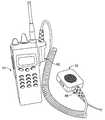
- FIG. 2is a drawing of a speaker-mic constructed in accordance with an embodiment of the present invention attached to an analog FM transceiver.
- FIG. 3is an electronic schematic drawing of the speaker-mic embodiment shown in FIG. 1 .
- FIG. 4is a functional block schematic drawing of a speaker-mic to illustrate functional operation in accordance with an embodiment of the present invention.
- FIG. 1is a simplified block schematic drawing of a speaker-microphone apparatus (speaker-mic) 12 constructed in accordance with an embodiment of the present invention and attached to an analog FM transceiver 10 .
- Transceiver 10comprises a receiver 11 and a transmitter 13 .
- speaker-mic 12Through an external connection with an external speaker-microphone 12 , hereafter speaker-mic 12 , receiver 11 transfers audio to a speaker 30 within speaker-mic 12 .
- a microphone 56controlled by a push-to-talk (PTT) switch 58 , produces audio that is sent to and modulates FM analog transmitter 13 , via connector 62 , when PTT switch 58 is pressed.
- PTTpush-to-talk
- An emergency switch 60is also provided that activates microphone 56 (e.g., in some embodiments, by interacting with PTT switch 58 ). However, emergency switch 60 further activates an encoder 14 that produces a signal that also modulates transmitter 13 via the connector 62 in a manner described below. It should be noted that other switches or buttons may be configured to provide the functionality of the various embodiments of the invention.
- an analog FM transceiver 10is used for transmitting digital signaling information (e.g., MDC-1200 frequency shift keyed [FSK] signaling information) without requiring modification to transceiver 10 .
- digital signaling informatione.g., MDC-1200 frequency shift keyed [FSK] signaling information
- the speaker-mic apparatus 12is used for transmit signal operations and a speaker output is used for receive signal operations.
- an off-the-shelf encoder module 14such as an MDC-1200 encoder module is used.
- encoder module 14is encased in an otherwise standard speaker-mic 12 (an external option used for analog FM transceiver 10 ) to generate MDC-1200 signaling.
- these embodiments of the present inventiondo not require modifications, changes, rework, or an optional slot to implement MDC-1200 proprietary signaling on analog FM transceivers 10 .
- Speaker-mic 12is configured to be compatible with typical frequency responses for the analog FM transceiver 10 through external level adjustments, whereas in at least one known prior art product in which encoder module 14 is internal to transceiver 10 , compatibility was maintained using internal circuits, software, or modules together with the internal radio level adjustments.
- embodiments of the present inventionprovide digital signaling without any need to change or modify an existing transceiver 10 .
- What appears to transceiver 10 as a standard speaker-mic 12 optionis additionally capable of digital signaling, such as MDC-1200 digital signaling, transparent to the operation and functionality of the transceiver 10 (e.g., standard FM transceiver).
- encoder module 14is assumed to be an MDC-1200 encoder module in the exemplary embodiments.
- An off-the-shelf encoder modulee.g., CIM-1000, manufactured by Cimarron Technologies Corp.
- CIM-1000manufactured by Cimarron Technologies Corp.
- a standard, unmodified speaker-mic, MIA-COM P7100 speaker-mic(either with or without an antenna), can be modified for use.
- an unmodified speaker-mic, MIA-COM P7100 speaker-mic, intrinsically-safe version, no antenna, vehicular charger versioncan be modified for use.
- a difference between these two microphonesis that in the latter, there is no RF antenna output 16 on the speaker-mic for an antenna to attach to the speaker-mic itself.
- the use of an RF antenna output 16can be advantageous when radiation from an antenna on transceiver 10 is blocked by a human body, as it is, for example, when transceiver 10 is clipped to a belt.
- MDC-1200 encodingis accomplished by injecting a signal on line 18 (via line 26 ) from encoder module 14 directly onto the mic audio line 20 of speaker-mic 12 .
- Microphone (mic) audio from mic audio line 20is processed by transceiver 10 through the standard analog FM transmitter path of transceiver 10 (e.g., pre-emphasis filter, limiter, post-limiter filter), and the MDC-1200 signaling 18 is sent through this same path regardless of the type of signaling being employed.
- Encoder module 14is used in speaker-mic 12 to permit MDC-1200 signaling.
- the connections to encoder module 14include: power 22 and ground 24 supply lines used to power encoder module 14 ; a data line 26 used to generate the MDC-1200 signaling to be coupled onto mic audio input 20 ; a sidetone output 28 used to generate a local sidetone to speaker 30 indicating the generation of the MDC-1200 signaling during the beginning of a transmission; a microphone mute output 32 used to mute mic audio 20 during MDC-1200 signaling and prevent voice falsing; an emergency input 34 (e.g., emergency switch 60 ) used for emergency automatic number identification (ANI) over the MDC-1200 signaling; push-to-talk (PTT) input 36 (e.g., PTT switch 58 ) used to initiate transmissions with the MDC-1200 signaling preceding the voice; and key output 37 used to generate PTT input 36 back to transceiver 10 .
- PTTpush-to-talk
- an optional resistor R 108can be used to route PTT switch S 1 input to transceiver 10 as well as encoder module 14 , and to bypass the delayed routing of PTT input 36 from encoder module 14 to transceiver 10 .
- Power input 22 to encoder module 14is the same as the power supply to speaker-mic 12 . This power supply is operated, for example, at a nominal 7.5 volts.
- MDC-1200 signaling data line 26is coupled into the mic audio path through resistor R 103 .
- Capacitor C 101performs deemphasis filtering to compensate for preemphasis filtering in transceiver 10 , which is a basic radio processing on the mic audio.
- the values of R 103 and C 101set a nominal signaling level of encoder module 14 onto mic audio path 20 .
- Microphone mute output 32drives MOSFET transistor Q 102 to float mic audio return line 48 during MDC-1200 signaling.
- the float of mic audio return line 48disables any unintentional mic audio, which would otherwise corrupt, interfere with, and/or override the MDC-1200 signal.
- Resistor R 105supplies bias and is used to activate MOSFET transistor Q 102 for mic voice audio when MDC-1200 signaling is not active.
- An optional resistormay be provided to enable mic audio at all times (e.g., provides a “hot mic”), but may affect MDC-1200 signaling if sufficient background noise is present.
- optional circuitry located on the auxiliary input to the encoder 14includes at least resistor R 112 and can be provided to hold off MDC-1200 signaling for some transceiver applications and modes (e.g., trunking).
- Sidetone output 28is coupled into audio amplifier 50 (IC1) of speaker-mic 12 through resistor R 104 .
- the value of R 104sets the level of the nominal sidetone to the speaker.
- PTT input 36is sent to encoder module 14 (as well as the PTT input 52 of transceiver 10 , if an optional resistor R 109 is installed), allowing transceiver 10 to start a transmission, and allowing encoder module 14 to start the MDC-1200 signaling at the beginning of each transmission from transceiver 10 .
- Emergency input 34is sent to encoder module 14 , allowing the MDC-1200 signaling to include emergency ID information.
- Non-emergency MDC-1200 signalingcan include an ANI ID.
- resistor R 106may be included to allow transceiver 10 to override the MDC-1200 emergency signaling with other transceiver dependent emergency signaling formats.
- resistor R 1078-UDL
- Transceiver 10reads resistor identifier R 107 and enables battery power (7-BATT) to speaker-mic 12 at all times.
- a fixed resistor of, for example, 470 ohmsis sensed by transceiver 10 for speaker-mic 12 operation.
- Resistor R 107enables speaker-mic power at all times, whereas without resistor R 107 , speaker-mic power is provided only when speaker audio is expected.
- Circuitrycomprising transistor Q 101 , resistors R 101 and R 102 are controlled by a speaker-mute control 54 (Rx Mute) to mute speaker amplifier 50 when all speaker audio is to be turned off.
- Optional resistor R 110can be used to enable audio amplifier 50 for test purposes only.
- Audio amplifier 50amplifies low level audio 70 from transceiver 10 and also drives internal speaker 30 and external headset audio provided through a jack 64 or 66 (routed through a connector J 1 ). Audio amplifier 50 is enabled via transistor Q 101 and associated circuitry, and is controlled by RX MUTE line (J 3 - 5 ) of transceiver 10 . Mic audio from internal microphone 56 is routed directly to transceiver 10 (J 3 - 4 ).
- Transistor Q 102 and associated circuitryis capable of muting mic audio during transmissions of MDC-1200 signaling.
- Switch 72can provide an audio gain control (high gain or low gain) by manual switching in one of two gain resistor settings (R 1 or R 2 ) in the audio path from transceiver 10 to audio amplifier 50 .
- Coupling capacitor C 1blocks a DC component on the audio from transceiver 10 .
- RF bypass capacitors C 21 -C 27 , C 10 -C 13 , and C 3 -C 8are used in the illustrated embodiment to eliminate possible RF (radio frequency) coupling into the circuits.
- encoder module 14is programmed via a separate programming input/output line 75 , ProgI/O.
- Line 75is bidirectional (input and output) and is used in conjunction with a programming cable 70 (e.g., CIM-CABLE) that may be obtained from the supplier of encoder module 14 .
- Programmingis routed through the cable 70 via programming connector jack 64 (J 4 )
- encoder module 14is programmed through programming connector jack 64 , which may be an earphone phono jack on speaker mic 12 (headset audio is eliminated, and a programming cable 70 , which may include a phono plug, is used only for programming encoder module 14 ).
- jack 64may be configured as headset audio output when a head set cable 68 (which may include a stereo plug) is plugged into jack 64 and as a headset audio output when a monophonic plug 70 is plugged into jack 64 .
- jack 64is configured as a programming port, and a separate audio jack 66 is provided for headset audio output.
- One suitable manner in which the encoder module 14 can be programmed in speaker-mic 12is via connection to a serial port of a personal computer.
- a terminal programsuch as “HyperTerminal” may be used.
- the HyperTerminal applicationis supplied in many versions of Microsoft Windows.
- Settingsthat can be programmed for embodiments of the present invention include the automatic number identification (ANI) ID and the emergency (EMR) ID, which can be the same. Other settings are push to talk (PTT) sidetone, which can be set to “Y” (yes) of “N” (no).
- the attack timealso can be changed (e.g., from 300 ms to 150 ms). Attack time generally refers to the time between (i) when a signal at the input of a device or circuit exceeds an activation threshold of the device or circuit and (ii) when that device or circuit reacts in a specified manners or to a specified degree to the input.
- the transmit (TX) modeadditionally can be set as either conventional or trunking, as appropriate. After programming, the cable is unplugged and the radio power is cycled.
- the settings appliedare the same as those indicated above, except that a time-out timer (TOT) is set to 000 seconds (thereby disabling the TOT), with the attack time changed (e.g., set to 300 ms, which is the carrier attack time for the system including the radio transceiver plus repeater), and KeyFollowsPTT is set to YES, so that the key out to the transceiver follows the PTT input to encoder module 14 .
- a separate KEY line to the transceivercan also permit MDC-1200 signaling at the end of a transmission.
- the settingsmay be changed to correspond to different operations or different settings may be provided to control different operations.
- Speaker-mic 12may further include microphone mute circuitry (e.g., Q 102 ) and a mic audio return line 48 , wherein microphone mute circuitry is configured to control the mic audio return line during transmission of a digital identification signal, a digital emergency signal, or both, so that mic audio does not interfere with the digital identification signal, the digital emergency signal, or both. Speaker-mic 12 may further include an antenna jack 16 mounted on the apparatus. In some embodiments of the method, a mic audio return line 48 is adjusted during transmission of a digital identification signal, a digital emergency signal, or both, so that mic audio does not interfere with the digital identification signal, the digital emergency signal, or both.
- microphone mute circuitrye.g., Q 102
- microphone mute circuitryis configured to control the mic audio return line during transmission of a digital identification signal, a digital emergency signal, or both, so that mic audio does not interfere with the digital identification signal, the digital emergency signal, or both.
- software in speaker-mic 12can be provided to initiate MDC signaling via a PTT line from the transceiver.
- PTTis an input to the transceiver, but PTT can be converted to an output for MDC signaling activation.
- MDC signalingcan be initiated via an emergency line from the transceiver.
- “emergency”is an input to the transceiver, but it can be converted to an output for MDC signaling activation.
- the transceivermay have a UDC Tx line that can be used to enable and/or disable the MDC signaling under various conditions, e.g., trunked mode operation, priority overrides, etc.
- FIG. 4is a functional block schematic drawing of speaker-mic 12 to illustrate functional operation of an exemplary embodiment of the present invention.
- speaker-mic 12is an external speaker/microphone apparatus for a radio transceiver 10 .
- Radio transceiver 10includes a connector 120 for connection to the speaker-mic 12 .
- Speaker-mic 12includes speaker 30 , microphone 56 , push-to-talk (PTT) switch 58 , and an emergency switch 60 .
- Encoder module 14(of any suitable type) is operatively coupled to PTT switch 58 and emergency switch 60 so that, in operation, a digital identification 144 is generated each time PTT switch 58 is pressed, and a digital emergency signal 142 is generated when emergency switch 60 is pressed.
- encoder module 14continuously generates digital identification signal 32 and emergency signal 142 .
- PTT switch 58When PTT switch 58 is pressed, audio from microphone 56 is added at audio summer 122 to digital identification signal 144 to generate an audio signal 84 that is coupled to connector 62 via PTT switch 58 , summer 104 , and output level controller 106 .
- the output of output level controller 106is a combination audio signal, which in various embodiments is the mic audio 20 .
- emergency switch 60is pressed, audio signal 84 is combined with emergency signal 142 by audio summer 96 and coupled to connector 62 via emergency switch 60 , audio summer 104 , and output level controller 106 .
- “Or” gate 94serves to operatively couple PTT switch 58 and emergency switch 60 to connector 62 so that PTT output 116 is activated and transceiver 10 is switched to a transmit mode when either PTT switch 58 or emergency switch 60 is pressed.
- emergency switch 60may be coupled via a logic line 140 to encoder module 14 to enable only the generation of the emergency signal 142 and not the identification signal 144 when emergency switch 60 is pressed. Also, when emergency switch 60 is pressed, encoder module 14 may mute speaker 30 (and/or microphone 56 , although not shown in FIG. 4 ) via mute output 32 . Although not shown in FIG. 4 , any or all of these additional features may be added to PTT switch 58 either in addition to, or instead of being added to emergency switch 60 .
- de-emphasis filters 130are added in emergency signal line 142 and/or identification signal line 144 .
- an RF signal 118 from transceiver 10is used to apply power to RF antenna output 16 , such as an RF jack, on speaker-mic 12 to power an antenna 80 located thereon.
- Additional jacks or ports 64 and 66are provided to program encoder module 14 and to output speaker audio, respectively.
- some embodiments of the present inventionprovide digital signaling without requiring specialized circuitry and software built into the analog FM transceiver, and can be added to existing transceivers without altering the internal wiring of the transceiver itself.
- the functional blocksare not necessarily indicative of the division between hardware circuitry.
- one or more of the functional blockse.g., processors or memories
- the programsmay be stand alone programs, may be incorporated as subroutines in an operating system, may be functions in an installed software package, and the like. It should be understood that the various embodiments are not limited to the arrangements and instrumentality shown in the drawings.
Landscapes
- Engineering & Computer Science (AREA)
- Computer Networks & Wireless Communication (AREA)
- Signal Processing (AREA)
- Databases & Information Systems (AREA)
- Transmitters (AREA)
- Transceivers (AREA)
Abstract
Description
Claims (20)
Priority Applications (2)
| Application Number | Priority Date | Filing Date | Title |
|---|---|---|---|
| US11/870,305US7831217B2 (en) | 2007-10-10 | 2007-10-10 | Method and apparatus to provide digital signaling without internal modification of analog FM transceiver |
| CA2640027ACA2640027C (en) | 2007-10-10 | 2008-09-30 | Method and apparatus to provide digital signaling without internal modification of analog fm transceiver |
Applications Claiming Priority (1)
| Application Number | Priority Date | Filing Date | Title |
|---|---|---|---|
| US11/870,305US7831217B2 (en) | 2007-10-10 | 2007-10-10 | Method and apparatus to provide digital signaling without internal modification of analog FM transceiver |
Publications (2)
| Publication Number | Publication Date |
|---|---|
| US20090098836A1 US20090098836A1 (en) | 2009-04-16 |
| US7831217B2true US7831217B2 (en) | 2010-11-09 |
Family
ID=40527676
Family Applications (1)
| Application Number | Title | Priority Date | Filing Date |
|---|---|---|---|
| US11/870,305Active2029-04-11US7831217B2 (en) | 2007-10-10 | 2007-10-10 | Method and apparatus to provide digital signaling without internal modification of analog FM transceiver |
Country Status (2)
| Country | Link |
|---|---|
| US (1) | US7831217B2 (en) |
| CA (1) | CA2640027C (en) |
Cited By (1)
| Publication number | Priority date | Publication date | Assignee | Title |
|---|---|---|---|---|
| US20150104034A1 (en)* | 2013-10-15 | 2015-04-16 | William H. Jennings | Apparatus for transferring programming data between a data upgrade/transfer unit and a communications device through a speaker microphone |
Families Citing this family (8)
| Publication number | Priority date | Publication date | Assignee | Title |
|---|---|---|---|---|
| USD602893S1 (en)* | 2008-07-02 | 2009-10-27 | Icom Incorporated | Portable communication device |
| US20100291883A1 (en)* | 2009-05-14 | 2010-11-18 | Motorola, Inc. | Method and apparatus for activating an emergency button in a portable radio |
| CN201774677U (en)* | 2010-01-11 | 2011-03-23 | 中兴通讯股份有限公司 | Push-to-talk handset |
| USD635945S1 (en)* | 2010-05-26 | 2011-04-12 | Motorola Solutions, Inc. | Communication device |
| US8862476B2 (en)* | 2012-11-16 | 2014-10-14 | Zanavox | Voice-activated signal generator |
| US9923534B2 (en)* | 2014-07-31 | 2018-03-20 | E.F. Johnson Company | Automatic volume control for land mobile radio |
| CN111246402B (en)* | 2020-01-06 | 2021-07-20 | 四川大学 | A method and device for modulating and demodulating digital identity information of ground-air wireless communication |
| CN114978228B (en)* | 2022-06-01 | 2024-02-20 | 中国人民解放军陆军军事交通学院镇江校区 | Multipurpose radio communication microphone |
Citations (19)
| Publication number | Priority date | Publication date | Assignee | Title |
|---|---|---|---|---|
| US4494244A (en)* | 1983-02-14 | 1985-01-15 | Alfred Arndt | Step-off device for aircraft voice communication system |
| US4495647A (en)* | 1982-12-06 | 1985-01-22 | Motorola, Inc. | Digital voice storage mobile |
| US4517561A (en)* | 1982-07-28 | 1985-05-14 | Motorola, Inc. | Selective call, paging and priority signalling system |
| US4646345A (en)* | 1986-06-09 | 1987-02-24 | Motorola, Inc. | Automatic unit ID for quasi-transmission trunked systems |
| US4700375A (en)* | 1986-10-10 | 1987-10-13 | Motorola, Inc. | Battery charging, reset, and data transfer system |
| US4792986A (en)* | 1985-12-11 | 1988-12-20 | General Electric Company | Portable radio system with externally programmable universal device connector |
| US4815128A (en)* | 1986-07-03 | 1989-03-21 | Motorola, Inc. | Gateway system and method for interconnecting telephone calls with a digital voice protected radio network |
| US4920567A (en)* | 1986-07-03 | 1990-04-24 | Motorola, Inc. | Secure telephone terminal |
| US5231355A (en)* | 1990-06-18 | 1993-07-27 | The Charles Machine Works, Inc. | Locator transmitter having an automatically tuned antenna |
| US5831515A (en)* | 1995-02-17 | 1998-11-03 | Carson Maunfacturing Company, Inc. | Electronic siren apparatus including an integrated handheld microphone and control handle |
| US5847679A (en)* | 1992-03-04 | 1998-12-08 | Motorola, Inc. | GPS based search and rescue system |
| US6466681B1 (en)* | 1999-09-21 | 2002-10-15 | Comprehensive Technical Solutions, Inc. | Weather resistant sound attenuating modular communications headset |
| US20060195261A1 (en)* | 2005-02-10 | 2006-08-31 | Homeland Integrated Security Systems, Inc. | Electronic device for tracking and monitoring assets |
| US20080004089A1 (en)* | 2006-06-30 | 2008-01-03 | Huizer Simon R | Inline Cable Adapter for Dissimilar Radio and Headset Combinations |
| US20080247373A1 (en)* | 2007-04-04 | 2008-10-09 | Telefonaktiebolaget Lm Ericsson (Publ) | Multicast push to talk groups, apparatus, and methods |
| US20090136058A1 (en)* | 2007-11-28 | 2009-05-28 | Samsung Electronics Co. Ltd. | Compatible circuit and method for 4- and 5-pole earphones and portable device using the same |
| US20090203331A1 (en)* | 1998-06-05 | 2009-08-13 | Netnumber, Inc. | Method and apparatus for accessing a network computer to establish a push-to-talk session |
| US20090296952A1 (en)* | 2008-05-30 | 2009-12-03 | Achim Pantfoerder | Headset microphone type detect |
| US20100111349A1 (en)* | 2008-10-31 | 2010-05-06 | Ume Voice, Inc. | Modular Input/Output Headset And Method Of Use |
- 2007
- 2007-10-10USUS11/870,305patent/US7831217B2/enactiveActive
- 2008
- 2008-09-30CACA2640027Apatent/CA2640027C/enactiveActive
Patent Citations (19)
| Publication number | Priority date | Publication date | Assignee | Title |
|---|---|---|---|---|
| US4517561A (en)* | 1982-07-28 | 1985-05-14 | Motorola, Inc. | Selective call, paging and priority signalling system |
| US4495647A (en)* | 1982-12-06 | 1985-01-22 | Motorola, Inc. | Digital voice storage mobile |
| US4494244A (en)* | 1983-02-14 | 1985-01-15 | Alfred Arndt | Step-off device for aircraft voice communication system |
| US4792986A (en)* | 1985-12-11 | 1988-12-20 | General Electric Company | Portable radio system with externally programmable universal device connector |
| US4646345A (en)* | 1986-06-09 | 1987-02-24 | Motorola, Inc. | Automatic unit ID for quasi-transmission trunked systems |
| US4815128A (en)* | 1986-07-03 | 1989-03-21 | Motorola, Inc. | Gateway system and method for interconnecting telephone calls with a digital voice protected radio network |
| US4920567A (en)* | 1986-07-03 | 1990-04-24 | Motorola, Inc. | Secure telephone terminal |
| US4700375A (en)* | 1986-10-10 | 1987-10-13 | Motorola, Inc. | Battery charging, reset, and data transfer system |
| US5231355A (en)* | 1990-06-18 | 1993-07-27 | The Charles Machine Works, Inc. | Locator transmitter having an automatically tuned antenna |
| US5847679A (en)* | 1992-03-04 | 1998-12-08 | Motorola, Inc. | GPS based search and rescue system |
| US5831515A (en)* | 1995-02-17 | 1998-11-03 | Carson Maunfacturing Company, Inc. | Electronic siren apparatus including an integrated handheld microphone and control handle |
| US20090203331A1 (en)* | 1998-06-05 | 2009-08-13 | Netnumber, Inc. | Method and apparatus for accessing a network computer to establish a push-to-talk session |
| US6466681B1 (en)* | 1999-09-21 | 2002-10-15 | Comprehensive Technical Solutions, Inc. | Weather resistant sound attenuating modular communications headset |
| US20060195261A1 (en)* | 2005-02-10 | 2006-08-31 | Homeland Integrated Security Systems, Inc. | Electronic device for tracking and monitoring assets |
| US20080004089A1 (en)* | 2006-06-30 | 2008-01-03 | Huizer Simon R | Inline Cable Adapter for Dissimilar Radio and Headset Combinations |
| US20080247373A1 (en)* | 2007-04-04 | 2008-10-09 | Telefonaktiebolaget Lm Ericsson (Publ) | Multicast push to talk groups, apparatus, and methods |
| US20090136058A1 (en)* | 2007-11-28 | 2009-05-28 | Samsung Electronics Co. Ltd. | Compatible circuit and method for 4- and 5-pole earphones and portable device using the same |
| US20090296952A1 (en)* | 2008-05-30 | 2009-12-03 | Achim Pantfoerder | Headset microphone type detect |
| US20100111349A1 (en)* | 2008-10-31 | 2010-05-06 | Ume Voice, Inc. | Modular Input/Output Headset And Method Of Use |
Non-Patent Citations (5)
| Title |
|---|
| CSC Control Signal, Digital ANI: Motorola MDC-1200 Format Encoder and Decoder, Downloaded from the main web page (http://www.controlsignal.com/) on Aug. 14, 2007, at 3:13 pm, 2 pgs. |
| CSC Control Signal, Frequently Asked Questions about the ID-12 Encoder, Downloaded from the main web page (http://www.controlsignal.com/products/id12faq.htm) on Aug. 14, 2007 at 3:18 pm, 3 pgs. |
| Midian Electronics, ANI-F-VX Multi-Form ANI Encoder, Manual Revision: Jun. 20, 2007, Covers Software Revisions: ANI-F: 1.0 & Higher, 6 pgs. |
| Vertex Standard Two-Way Radio VMDE-200 and VME-100 plug-in ANI boards by Cimarron Technologies, VMDE-200 Encode and Decode/Display of MDC-1200, GE Star & DTMF, Main Information page downloaded from website (http://www.frwiz.com/vertexstandard/VMDE-200-VME-100.htm) on Tuesday, Aug. 14, 2007 at 3:46 pm, 5 pgs. |
| Vertex Standard Two-Way Radio VMDE-200 and VME-100 plug-in ANI boards by Cimarron Technologies, VMDE-200 Encode and Decode/Display of MDC-1200, GE Star & DTMF, Main Information page downloaded from website (http://www.frwiz.com/vertexstandard/VMDE-200—VME-100.htm) on Tuesday, Aug. 14, 2007 at 3:46 pm, 5 pgs. |
Cited By (1)
| Publication number | Priority date | Publication date | Assignee | Title |
|---|---|---|---|---|
| US20150104034A1 (en)* | 2013-10-15 | 2015-04-16 | William H. Jennings | Apparatus for transferring programming data between a data upgrade/transfer unit and a communications device through a speaker microphone |
Also Published As
| Publication number | Publication date |
|---|---|
| CA2640027C (en) | 2016-07-12 |
| US20090098836A1 (en) | 2009-04-16 |
| CA2640027A1 (en) | 2009-04-10 |
Similar Documents
| Publication | Publication Date | Title |
|---|---|---|
| US7831217B2 (en) | Method and apparatus to provide digital signaling without internal modification of analog FM transceiver | |
| EP0331435B1 (en) | Radio telephone apparatus | |
| US6792296B1 (en) | Portable wireless communication device and methods of configuring same when connected to a vehicle | |
| US6226529B1 (en) | System for providing a simultaneous data and voice channel within a single channel of a portable cellular telephone to provide position-enhanced cellular services (PECS) | |
| US8195253B2 (en) | Wireless portable radio vehicle communication system | |
| US20070015537A1 (en) | Wireless Hands-Free Audio Kit for Vehicle | |
| US9054781B2 (en) | Land mobile radio and adapter for use with standard mobile phone headset | |
| WO1996018275B1 (en) | System for providing simultaneous data and voice communication | |
| US20130171947A1 (en) | System and method of duplex wireless audio link over broadcast channels | |
| KR20040024453A (en) | An Stereophonic Apparatus Having Multiple Switching Function And An Apparatus For Controlling Sound Signal | |
| WO2013097389A1 (en) | Method and device for implementing built-in antenna of mobile television and fm radio | |
| RU2146852C1 (en) | Cellular telephone adapter | |
| CN202998085U (en) | A vehicle station hand microphone | |
| JP2006067545A (en) | Car audio hands-free system and bidirectional speech communication method | |
| KR100319310B1 (en) | Hands-free equipment for vehicles | |
| WO2000010311A1 (en) | System enabling telephone communications through an audio equipment device | |
| CN101083808A (en) | Wireless playing method and system for handset audio | |
| CN219644064U (en) | Wireless microphone system supporting dual modes of receiving and transmitting | |
| CN111817754B (en) | Vehicle-mounted Bluetooth pair earphone control system | |
| AU2019101106A4 (en) | This invention integrates a 2-way radio and Bluetooth stereo audio chip capabilities. It is capable of transmitting and receiving 2-way radio signals, perform hands-free telephony using Bluetooth and act as Audio Sink via Bluetooth or auxiliary input into the device. | |
| KR20000040313A (en) | Hands-free device of cellular phone using car audio system | |
| KR20030066578A (en) | MP3 Player With Transmitter Interface Include Memory Chip And Cigar Plug | |
| KR20020004153A (en) | Hands free phone equipment by using the radio system in automobile | |
| JP3784584B2 (en) | Transmission signal detection device and hands-free device | |
| US5391928A (en) | Switching circuit having a reduced output impedance |
Legal Events
| Date | Code | Title | Description |
|---|---|---|---|
| AS | Assignment | Owner name:M/A-COM, INC., MASSACHUSETTS Free format text:ASSIGNMENT OF ASSIGNORS INTEREST;ASSIGNORS:YURMAN, BRUNO;JAMERSON, ERIC MATTHEW;TREDWAY, JOSHUA BURKE;AND OTHERS;REEL/FRAME:019964/0840;SIGNING DATES FROM 20071005 TO 20071008 | |
| AS | Assignment | Owner name:PINE VALLEY INVESTMENTS, INC., NEVADA Free format text:ASSIGNMENT OF ASSIGNORS INTEREST;ASSIGNORS:TYCO ELECTRONICS GROUP S.A.;TYCO ELECTRONICS CORPORATION;THE WHITAKER CORPORATION;AND OTHERS;REEL/FRAME:023065/0269 Effective date:20090529 Owner name:PINE VALLEY INVESTMENTS, INC.,NEVADA Free format text:ASSIGNMENT OF ASSIGNORS INTEREST;ASSIGNORS:TYCO ELECTRONICS GROUP S.A.;TYCO ELECTRONICS CORPORATION;THE WHITAKER CORPORATION;AND OTHERS;REEL/FRAME:023065/0269 Effective date:20090529 | |
| STCF | Information on status: patent grant | Free format text:PATENTED CASE | |
| FPAY | Fee payment | Year of fee payment:4 | |
| AS | Assignment | Owner name:PINE VALLEY INVESTMENTS, LLC, DELAWARE Free format text:CHANGE OF NAME;ASSIGNOR:PINE VALLEY INVESTMENTS, INC.;REEL/FRAME:043277/0889 Effective date:20110629 Owner name:EAGLE TECHNOLOGY, LLC, DELAWARE Free format text:MERGER;ASSIGNOR:PINE VALLEY INVESTMENTS, LLC;REEL/FRAME:043277/0986 Effective date:20170517 | |
| MAFP | Maintenance fee payment | Free format text:PAYMENT OF MAINTENANCE FEE, 8TH YEAR, LARGE ENTITY (ORIGINAL EVENT CODE: M1552) Year of fee payment:8 | |
| AS | Assignment | Owner name:AVAGO TECHNOLOGIES INTERNATIONAL SALES PTE. LIMITE Free format text:CORRECTIVE ASSIGNMENT TO CORRECT THE EFFECTIVE DATE OF MERGER TO 9/5/2018 PREVIOUSLY RECORDED AT REEL: 047196 FRAME: 0687. ASSIGNOR(S) HEREBY CONFIRMS THE MERGER;ASSIGNOR:AVAGO TECHNOLOGIES GENERAL IP (SINGAPORE) PTE. LTD.;REEL/FRAME:047630/0344 Effective date:20180905 | |
| MAFP | Maintenance fee payment | Free format text:PAYMENT OF MAINTENANCE FEE, 12TH YEAR, LARGE ENTITY (ORIGINAL EVENT CODE: M1553); ENTITY STATUS OF PATENT OWNER: LARGE ENTITY Year of fee payment:12 |