US7830892B2 - VLAN translation in a network device - Google Patents
VLAN translation in a network deviceDownload PDFInfo
- Publication number
- US7830892B2 US7830892B2US11/289,370US28937005AUS7830892B2US 7830892 B2US7830892 B2US 7830892B2US 28937005 AUS28937005 AUS 28937005AUS 7830892 B2US7830892 B2US 7830892B2
- Authority
- US
- United States
- Prior art keywords
- packet
- identifier
- network
- network device
- predefined
- Prior art date
- Legal status (The legal status is an assumption and is not a legal conclusion. Google has not performed a legal analysis and makes no representation as to the accuracy of the status listed.)
- Active, expires
Links
Images


Classifications
- H—ELECTRICITY
- H04—ELECTRIC COMMUNICATION TECHNIQUE
- H04L—TRANSMISSION OF DIGITAL INFORMATION, e.g. TELEGRAPHIC COMMUNICATION
- H04L12/00—Data switching networks
- H04L12/28—Data switching networks characterised by path configuration, e.g. LAN [Local Area Networks] or WAN [Wide Area Networks]
- H04L12/46—Interconnection of networks
- H04L12/4641—Virtual LANs, VLANs, e.g. virtual private networks [VPN]
- H04L12/4645—Details on frame tagging
- H—ELECTRICITY
- H04—ELECTRIC COMMUNICATION TECHNIQUE
- H04J—MULTIPLEX COMMUNICATION
- H04J3/00—Time-division multiplex systems
- H04J3/16—Time-division multiplex systems in which the time allocation to individual channels within a transmission cycle is variable, e.g. to accommodate varying complexity of signals, to vary number of channels transmitted
- H04J3/1605—Fixed allocated frame structures
- H04J3/1611—Synchronous digital hierarchy [SDH] or SONET
- H04J3/1617—Synchronous digital hierarchy [SDH] or SONET carrying packets or ATM cells
Definitions
- the present inventionrelates to a network device in a data network and more particularly to a system and method of mapping multiple packets for multiple customers associated with a service provider to a single tunnel.
- a packet switched networkmay include one or more network devices, such as an Ethernet switching chip, each of which includes several modules that are used to process information that is transmitted through the device.
- the deviceincludes an ingress module, a Memory Management Unit (Mh4I-J) and an egress module.
- the ingress moduleincludes switching functionality for determining to which destination port a packet should be directed.
- the MMUis used for storing packet information and performing resource checks.
- the egress moduleis used for performing packet modification and for transmitting the packet to at least one appropriate destination port.
- One of the ports on the devicemay be a CPU port that enables the device to send and receive information to and from external switching/routing control entities or CPUs.
- a service providermay use one or more network devices to provide services to multiple customers, wherein each customer transmits packets requiring one or more services.
- packets requesting the same servicesneed to be classified and processed in a way that reduces network bottleneck.
- Prior network devicesassociated a unique service provider identifier with each classification. This enabled the network devices to map several packets to the service provider identifier and to provide the appropriate services to the packets without individually examining each packet. As the packets entered into the network device, the service provider identifier was inserted into each packet.
- the packet flowneeds to be monitored to determine if the network device is functioning properly.
- the packets being sent to a given portcould be “mirrored” to another port where the packet flow could be examined.
- the mirroring processis important in that the flow of the packets to a given destination port need not be interrupted to examine the flow to that destination port. Therefore, in these devices, the packets that were received by a “mirrored-to” port were examined at the latter port with no disruption to the flow of packets to the actual destination port.
- the packet that is mirroredis modified as a consequence of the inserted service provider identifier.
- the headeris modified by the receiving port when the service provider identifier is inserted into the packet.
- the receiving portis supposed to transmit the unmodified packet to a destination port, after inserting the service provider identifier, the packet that is forwarded to the destination port is indeed a modified packet. This can be a problem if a copy of the received packet is what is needed at a given destination port, such as the mirrored-to port.
- FIG. 1illustrates a network device in which an embodiment of the present invention may be implemented
- FIG. 2illustrates a centralized ingress pipeline architecture, according to one embodiment of the present invention
- FIG. 3illustrates a centralized egress pipeline architecture of an egress stage, according to one embodiment of the present invention
- FIG. 4illustrates a table lookup stage in the egress pipeline architecture
- FIG. 5illustrates an embodiment of the invention in which VLAN translation is implemented on at least two devices
- FIG. 6 aillustrates a packet that is transmitted between customers in a service provider network
- FIG. 6 billustrates one embodiment of a packet that is translated in a service provider network
- FIG. 6 cillustrates another embodiment of a packet that is translated in the service provider network.
- FIG. 1illustrates a network device, such as a switching chip, in which an embodiment the present invention may be implemented.
- Device 100includes an ingress module 102 , a MMU 104 , and an egress module 106 .
- Ingress module 102is used for performing switching functionality on an incoming packet.
- MMU 104is used for storing packets and performing resource checks on each packet.
- Egress module 106is used for performing packet modification and transmitting the packet to an appropriate destination port.
- Each of ingress module 102 , MMU 104 and Egress module 106implements multiple cycles for processing instructions generated by that module.
- Device 100implements a pipelined approach to process incoming packets.
- the device 100has the ability of the pipeline to process, according to one embodiment, one packet every clock cycle.
- the device 100includes a 133.33 MHz core clock. This means that the device 100 architecture is capable of processing 133.33M packets/sec.
- Device 100may also include one or more internal fabric high speed ports, for example a HiGigTM, high speed port 108 a - 108 x , one or more external Ethernet ports 109 a - 109 x , and a CPU port 110 .
- High speed ports 108 a - 108 xare used to interconnect various network devices in a system and thus form an internal switching fabric for transporting packets between external source ports and one or more external destination ports. As such, high speed ports 108 a - 108 x are not externally visible outside of a system that includes multiple interconnected network devices.
- CPU port 110is used to send and receive packets to and from external switching/routing control entities or CPUs.
- CPU port 110may be considered as one of external Ethernet ports 109 a - 109 x .
- Device 100interfaces with external/off-chip CPUs through a CPU processing module 111 , such as a CMIC, which interfaces with a PCI bus that connects device 100 to an external CPU.
- a CPU processing module 111such as a CMIC, which interfaces with a PCI bus that connects device 100 to an external CPU.
- traffic in device 100is routed from an external Ethernet source port to one or more unique destination Ethernet ports 109 a - 109 x .
- device 100supports physical Ethernet ports and logical (trunk) ports.
- a physical Ethernet portis a physical port on device 100 that is globally identified by a global port identifier.
- the global port identifierincludes a module identifier and a local port number that uniquely identifies device 100 and a specific physical port.
- the trunk portsare a set of physical external Ethernet ports that act as a single link layer port. Each trunk port is assigned a global a trunk group identifier (TGID).
- TGIDtrunk group identifier
- device 100can support up to 128 trunk ports, with up to 8 members per trunk port, and up to 29 external physical ports.
- Destination ports 109 a - 109 x on device 100may be physical external Ethernet ports or trunk ports. If a destination port is a trunk port, device 100 dynamically selects a physical external Ethernet port in the trunk by using a hash to select a member port. The dynamic selection enables device 100 to allow for dynamic load sharing between ports in a trunk.
- Packetsmay enter device 100 from a XBOD or a GBOD.
- the XBODis a block that has one 10 GE/12G MAC and supports packets from high speed ports 108 a - 108 x .
- the GBODis a block that has 12 10/100/1G MAC and supports packets from ports 109 a - 109 x.
- FIG. 2illustrates a centralized ingress pipeline architecture 200 of ingress module 102 .
- Ingress pipeline 200processes incoming packets, primarily determines an egress bitmap and, in some cases, figures out which parts of the packet may be modified.
- Ingress pipeline 200includes a data holding register 202 , a module header holding register 204 , an arbiter 206 , a configuration stage 208 , a parser stage 210 , a discard stage 212 and a switch stage 213 .
- Ingress pipeline 200receives data from the XBOD, GBOD or CPU processing module 111 and stores cell data in data holding register 202 .
- Arbiter 206is responsible for scheduling requests from the GBOD, the XBOD and CPU.
- Configuration stage 208is used for setting up a table with all major port-specific fields that are required for switching.
- Parser stage 210parses the incoming packet and a high speed module header, if present, handles tunnelled packets through Layer 3 (L3) tunnel table lookups, generates user defined fields, verifies Internet Protocol version 4 (IPv4) checksum on outer IPv4 header, performs address checks and prepares relevant fields for downstream lookup processing.
- Discard stage 212looks for various early discard conditions and either drops the packet and/or prevents it from being sent through pipeline 200 .
- Switching stage 213performs all switch processing in ingress pipeline 200 , including address resolution.
- Ingress module 102then transmits the packet to MMU 104 which applies all resource accounting and aging logic to packet 200 .
- MMU 104uses a source port number to perform resource accounting. Thereafter, MMU 104 forwards the packet to egress module 106 .
- egress module 106Upon receiving the packet from MMU 104 , egress module 106 supports multiple egress functions for a 72 gigabyte port bandwidth and a CPU processing bandwidth. According to one embodiment, the egress module 106 is capable of handling more than 72 Gig of traffic, i.e., 24 one GE port, 4 high speed ports (12G) and a CPU processing port of 0.2 GE. The egress module 106 receives original packets, as inputted from Ethernet ports 109 a - 109 x , from MMU 104 , and may either transmit modified or unmodified packets to destination ports 109 a - 109 x .
- all packet modifications within device 100are made in egress module 106 and the core processing of egress module 106 is capable of running faster than the processing of destination ports 109 a - 109 x . Therefore, egress module 106 provides a stall mechanism on a port basis to prevent ports 109 a - 109 x from becoming overloaded and thus services each port based on the speed of the port.
- the egress module 106is connected to the MMU 104 by a 1024 bit data interface and all packets transmitted from the MMU 104 pass through egress module 106 .
- the MMU 104passes unmodified packet data and control information to egress module 106 .
- the control informationincludes the results of table lookups and switching decisions made in ingress module 102 .
- the data bus from MMU 106is shared across all ports 108 and 109 and the CPU processing 111 . As such, the bus uses a “request based” Time Division Multiplexing (TDM) scheme, wherein each Gig port has a turn on the bus every 72 cycles and each high speed Port 108 has a turn every 6 cycles.
- TDMTime Division Multiplexing
- CPU processed packet datais transmitted over bubbles—free spaces occurring on the bus.
- the egress module 106parses the packet data, performs table lookups, executes switch logic, modifies, aligns and further buffers the packet before the data is transmitted to the appropriate destination port 109 a - 109 x .
- egress module 106is connected to CPU processing module 111 through a 32 bit S-bus interface which the CPU uses to send requests to egress module 106 .
- the requestsare typically for reading the egress module's resources, i.e., registers, memories and/or stat counters.
- the egress module 106Upon receiving a request, the egress module 106 converts the request into a command and uses a mechanism, described in detail below, for storing and inserting CPU instructions into a pipeline wherever there is an available slot on the pipeline.
- FIG. 3illustrates a centralized egress pipeline architecture of egress stage 106 .
- the egress pipelineincludes an arbiter 302 , parser 306 , a table lookup stage 308 , a decision stage 310 , a modification stage 312 and a data buffer 314 .
- the arbiter 302provides arbitration for accessing egress pipeline resources between packet data and control information from MMU 104 and information from the CPU.
- Parser 306performs packet parsing for table lookups and modifications.
- Table lookup stage 308performs table lookups for information transmitted from parser 306 .
- Decision stage 310is used for deciding whether to modify, drop or otherwise process the packet.
- Modification stage 312makes modification to the packet data based on outputs from previous stages of the ingress module.
- All incoming packet data from MMU 104is transmitted to an initial packet buffer 304 .
- the initial packet bufferis 1044 bits wide and 18 words deep.
- Egress pipeline 300receives two inputs, packet data and control information from MMU 104 and CPU operations from the s-bus.
- Initial packet buffer 304stores packet data and keeps track of any empty cycles coming from MMU 104 .
- Initial packet buffer 304outputs its write address and parser 306 passes the latest write address with pipeline instructions to modification stage 314 .
- Arbiter 302collects packet data and control information from MMU 104 and read/write requests to registers and memories from the CPU and synchronizes the packet data and control information from MMU 104 and writes the requests from the CPU in a holding register. Based on the request type from the CPU, arbiter 302 generates pipeline register and memory access instructions and hardware table initialization instructions. After arbiter 302 collects packet data, CPU requests and hardware table initialization messages, it generates an appropriate instruction which is transmitted to parser 306 .
- parser 306After receiving an instruction from arbiter 304 , parser 306 parses packet data using control information and a configuration register value transmitted from arbiter 306 . According to an embodiment, the packet data is parsed to obtained L4 and L3 fields which appear in the first 148 bytes of the packet.
- Table lookup stage 308then receives all packet fields and register values from parser 306 .
- FIG. 4further illustrates table lookup stage 308 .
- Table lookup stage 308includes a L 3 Module 402 , a VLAN stage 404 , a VLAN translation stage 406 , IP tunneling lookup stage 408 .
- L3 Module 402includes an 8 k deep Next Hop Table 410 and a 4K deep Interface table 412 .
- Next Hop table 410is indexed based on a 13 bit wide next hop index from MMU 104 and Next Hop table 410 provides a MAC Address and an Interface Number that is used, depending on the type of packet, to index Interface table 412 .
- table lookup stage 308decodes the address and writes or reads data from corresponding tables.
- VLAN stage 404is used to obtain VLAN related information and a spanning tree state of an outgoing port.
- VLAN stage 404includes a VLAN table 414 and a stage (STG) table 416 .
- VLAN table 414is indexed based on the VLAN IDs from either the packet or Interface table 412 . If a VLAN table lookup results in a “miss”, i.e., an invalid VLAN, then the packet may be dropped. If the VLAN entry is valid but the outgoing port is not a member of the VLAN, then the packet may be also dropped.
- the VLAN tableoutputs a VLAN membership, untagged bitmap, and a STG group number which is used to index STG table 416 .
- STG table 416outputs an STG vector which contains the spanning tree state of the outgoing ports.
- VLAN stage 404also determines whether the packet should be modified in egress pipeline 300 for CPU and ingress mirroring cases.
- VLAN translation stage 406translates the incoming VLAN to a new one and searches various tables.
- VLAN translation stage 406includes a Content Addressable Memory (CAM) 418 and an associated Data Random Addressable Memory (RAM) 520 .
- CAM 418is searched with the VLAN ID and the destination port number and if an associated entry is found, an address is obtained from CAM 418 to access the associated Data RAM 520 .
- IP tunneling lookup stage 408obtains a partial Tunnel IP header from appropriate tables, registers and parsed packet fields.
- IP tunneling lookup stage 408includes an IP tunnel table 522 that is indexed issuing a tunnel index from interface table 412 and outputs tunnel type, among other information, which is used to distinguish among tunnel protocols that are implemented in egress pipeline 300 .
- decision stage 310a decision is made as to whether to modify, drop or otherwise process the packet. For example, decision stage 310 first looks for flush bits at the beginning of the packet transmission and if the flush bits are set, the packets are marked “dropped”. In an embodiment of the invention, if a flush bit for a packet is set for a packet already in transmission, the packet is completely transmitted and the next packet is flushed. In another example, MMU 104 may mark packets as Purge, Aged or Cell Error and decision stage 310 may either drop or transmit these packets but mark them as erroneous.
- the decision stage 310may drop the packet if certain fields are set.
- Decision stage 308also determines if the packet need to be L4 switched or L3 routed and the type of mirroring functions that need to be performed on the packets.
- Modification stage 312thereafter constructs a Tunnel IP Header and a module header for the packet, makes replacement changes in the packet and computes an IP checksum for outer and inner IP headers.
- Modification stage 312receives a packet data interface from the initial buffer 304 which enables modification stage 312 to provide a read address to initial buffer 304 and in response obtain the packet data and basic control data.
- Modification stage 312then generates Middle of Packet and End of Packet instructions based on the data received from initial buffer 304 and makes changes based on these commands.
- Modification stage 312also receives all packet decisions and pipeline commands decision stage 310 and uses this information to make further changes to the packet. Specifically, all fields of the tunnel IP header, which need to be filled by incoming packet fields, are filled.
- Modification stage 312further reads back packets and control information from initial buffer 304 and performs all packet modifications and replacements of fields. It outputs Cpu operations and hardware commands and data and addresses associated with them on one bus and outputs packet data and control information on another bus. Additionally, modification stage 312 performs physical encapsulation and decapsulation of headers and tag removal and insertions. If a packet is going to a high speed port, modification stage 312 converts the packet from Ethernet format to high speed format. Modification stage 312 also aligns the packet by padding packets smaller than 64 bytes and removes holes by aligning data to a 1314 bit boundary. Thereafter, a 1314 bit “complete” data word is output from modification stage 312 to the data buffer 314 .
- Data buffer 314stores completed data words from modification stage 312 in memory. Before the egress pipeline sends packets out to destination ports 109 a - 109 x , the packet data are stored in the data buffer 314 for pipeline latency and port speed matching. Data buffer 314 is capable of requesting data from MMU 104 whenever it has a free space.
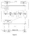
- FIG. 5illustrates an embodiment of the invention in which VLAN translation is implemented on at least two network devices, as described above, used by a service provider network.
- the service provider network 500includes first device 502 and a second device 504 each of which includes a user network interface port 506 a and 506 b for receiving and/or transmitting packets to customers 510 a - 510 e of service provider network 500 .
- Each of first and second devices 502 and 504also includes a network to network interface 508 a and 508 b for communicating with each other.
- FIG. 6 aillustrates a packet 600 that is transmitted between customers 510 a - 510 e connected to service provider network 500 .
- Packet 600includes a destination address 602 , a source address 604 , an inner Internet type identifier (ITPID) 606 and a customer identifier (CVID) 608 .
- IPIDinner Internet type identifier
- CVIDcustomer identifier
- packet 600is transmitted from customer 510 a to customer 510 e , upon receipt of packet 600 by first device 502 , packet 600 is translated based on an associated service provider identifier, classified and transmitted to second device 504 where packet 500 is restored to its original state before it is transmitted out of user network interface port 506 b to customer 510 e .
- packet 600is translated based on an associated service provider identifier, classified and transmitted to second device 504 where packet 500 is restored to its original state before it is transmitted out of user network interface port 506 b to customer 510 e .
- neither of customers 510 a nor 510 eknows anything about the translation.
- a double tag modein order to properly classify the packet, a double tag mode must be enabled in the entire system. Thereafter, upon receipt of packet 600 on incoming user network interface port 506 a , first device 502 obtains ITPID 606 from the incoming packet and compares ITPID 606 with a configured ITPID. If there is a match, first device 502 provides predefined map or translation services to the packet.
- first device 502indexes a VLAN Translation Table, with CVID 608 and the ingress port number. First device 502 then obtains a service provider identifier and depending on the action associated with the service provider identifier, an outer Internet type identifier (OTPID) 702 and service provider identifier 704 are either added to packet 600 , as shown in FIG. 6 b , or used to replace ITPID 606 and CVID 508 , as shown in FIG. 6 c . As shown in FIG. 6 c , for those service providers that want to save bandwidth on packets that are transmitted in their service provider network 500 , OTPID 702 and service provider identifier 704 may replace ITPID 606 and CVID 608 , instead of being added to packet 600 .
- OTPID 702 and service provider identifier 704may replace ITPID 606 and CVID 608 , instead of being added to packet 600 .
- each device 502 and 504may include multiple service provider identifiers based on different parameters, for example based on protocols or ports, wherein each of the service provider identifiers has it own set of parameters. So anytime a packet, for example packet 600 , is received on user network interface port 506 a and 506 b , the packet is either translated by replacing ITPID 606 and CVID 608 that are already in packet 600 with OTPID 702 and service provider identifier 704 obtained from the VLAN translation table or by inserting OTPID 702 and service provider identifier 704 into packet 600 .
- the packetis placed on higig port, wherein the higig header includes service provider identifier 704 .
- second device 504indexes an egress VLAN translation table using the egress port and the service provider identifier.
- Second device 504obtains the corresponding CVID 608 , removes the added OTPID 702 and service provider identifier 704 from the packet and puts CVID 608 back into the packet before the packet is sent out to an egress port.
- second device 504indexes the egress VLAN translation table to obtain the appropriate CVID.
- second device 504examines a VLAN table to determine if a un-tag bit map is set for the egress port. If it is, second device 504 removes OTPID 702 and service provider identifier 704 from the packet. According to one embodiment of the invention, if there is a miss when second device indexes the egress VLAN translation table, second device 504 still removes OTPID 702 and service provider identifier 704 from the packet.
- device 502 or 504parses one tag from the packet
- device 502 or 504parses two tags from the packet.
- a port on each of device 502 or 504may be programmed as a network to network port 508 .
- an ingress tag in the module header of each packetis set to either switch or mirror the packet. For switching, the ingress tag bit signifies that the packet has two tags and is identified by a two tags field. For mirroring, the ingress tag bit signifies that the packet came into the device as tagged.
- the set two tags fieldis set at the ingress device. Thereafter, at an egress or high speed port, if the two tags field is set, one tag is parsed from the packet.
- device 502 or 504determines if the port is a network to network interface port 508 and if a predefined OTPID is equal to the OTPID in the packet, device 502 or 504 initializes an identifier counter and the two tags field. Then based on an outer identifier, device 502 or 504 determines if a VLAN translation disable function is enabled, and if it is, device 502 or 504 does not change the packet and sets an OTPID match field.
- Device 502 or 504also determines if a VLAN translation replace function is enabled based on the outer identifier, and if it is, device 502 or 504 sets a MMU identifier to a VLAN translation identifier and sets an OTPID match field. Device 502 or 504 further determines if a VLAN translation add function is enabled based on the outer identifier, and if it is, device 502 or 504 determines that this is an illegal case and sets the OTPID match field. Device 502 or 504 also determines if a VLAN translation miss function is enabled based on the outer identifier, and if it is, device 502 or 504 does not change the packet and sets the OTPID match field.
- device 502 or 504determines if the packet ITPID 606 is equal to a predefined ITPID and, if it is, sets an ITPID match field. At this point, if the OTPID match field is also set, device 502 and 504 sets the two tags field or else it initializes the two tags field. Device 502 or 504 then determines if the ingress port is user network interface port 506 . If it is, device 502 or 504 determines if the VLAN translation disable function is enabled based on an inner identifier, and if it is, device 502 or 504 sets the MMU identifier with the VLAN identifier and sets the identifier counter.
- Device 502 or 504also determines if the VLAN translation replace function is enabled based on the inner identifier, and if it is, device 502 or 504 sets the MMU identifier to the VLAN translation identifier and initializes the identifier counter. Device 502 or 504 further determines if a VLAN translation add function is enabled based on the inner identifier, and if it is, device 502 or 504 sets the MMU identifier to the VLAN translation identifier and sets the identifier counter and the two tags field.
- Device 502 or 504further determines if a VLAN translation miss function is enabled based on the inner identifier, and if it is, device 502 or 504 sets the MMU identifier to a port identifier and sets the identifier counter and the two tags field.
- ingress device 502 or 504determines if the OTPID match field and ITPID match field are set, and if they are not, device 502 or 504 identifies the packet as untagged, initializes the two tags field, sets the MMU identifier to the VLAN identifier and sets the identifier counter.
- the associated devicedetermines if the 2 tags field in the high speed module header is set, parses one tag in the packet and sets the identifier counter.
- the egress portparses one tag in the packet.
- the egress portdetermines if the identifier counter is set, and if it is not, replaces predefined fields in the packet.
- device 502 or 504determines if the source port is network to network port 508 . Device 502 or 504 further determines if the packet OTPID is equal to a predefined OTPID and if it is, sets the two tags field in the packet's high speed module header. If on the other hand the packet OTPID is not equal to a predefined OTPID, device 502 or 504 initializes the two tags field in the packet's high speed module header. Then device 502 or 504 determines if the source port is user network interface port 506 and sets the two tags field in the packet's high speed module header.
- the above-discussed configuration of the inventionis, in a preferred embodiment, embodied on a semiconductor substrate, such as silicon, with appropriate semiconductor manufacturing techniques and based upon a circuit layout which would, based upon the embodiments discussed above, be apparent to those skilled in the art.
- a person of skill in the art with respect to semiconductor design and manufacturingwould be able to implement the various modules, interfaces, and tables, buffers, etc. of the present invention onto a single semiconductor substrate, based upon the architectural description discussed above. It would also be within the scope of the invention to implement the disclosed elements of the invention in discrete electronic components, thereby taking advantage of the functional aspects of the invention without maximizing the advantages through the use of a single semiconductor substrate.
- network devicesmay be any device that utilizes network data, and can include switches, routers, bridges, gateways or servers.
- network devicesmay include switches, routers, bridges, gateways or servers.
- packetsin the context of the instant application, can include any sort of datagrams, data packets and cells, or any type of data exchanged between network devices.
Landscapes
- Engineering & Computer Science (AREA)
- Computer Security & Cryptography (AREA)
- Computer Networks & Wireless Communication (AREA)
- Signal Processing (AREA)
- Data Exchanges In Wide-Area Networks (AREA)
Abstract
Description
Claims (19)
Priority Applications (1)
| Application Number | Priority Date | Filing Date | Title |
|---|---|---|---|
| US11/289,370US7830892B2 (en) | 2004-11-30 | 2005-11-30 | VLAN translation in a network device |
Applications Claiming Priority (3)
| Application Number | Priority Date | Filing Date | Title |
|---|---|---|---|
| US63154804P | 2004-11-30 | 2004-11-30 | |
| US68640205P | 2005-06-02 | 2005-06-02 | |
| US11/289,370US7830892B2 (en) | 2004-11-30 | 2005-11-30 | VLAN translation in a network device |
Publications (2)
| Publication Number | Publication Date |
|---|---|
| US20060114915A1 US20060114915A1 (en) | 2006-06-01 |
| US7830892B2true US7830892B2 (en) | 2010-11-09 |
Family
ID=36567326
Family Applications (1)
| Application Number | Title | Priority Date | Filing Date |
|---|---|---|---|
| US11/289,370Active2028-07-13US7830892B2 (en) | 2004-11-30 | 2005-11-30 | VLAN translation in a network device |
Country Status (1)
| Country | Link |
|---|---|
| US (1) | US7830892B2 (en) |
Cited By (4)
| Publication number | Priority date | Publication date | Assignee | Title |
|---|---|---|---|---|
| US20060114908A1 (en)* | 2004-11-30 | 2006-06-01 | Broadcom Corporation | Policy based routing using a fast filter processor |
| US20060140130A1 (en)* | 2004-11-30 | 2006-06-29 | Broadcom Corporation | Mirroring in a network device |
| US20100142536A1 (en)* | 2004-11-30 | 2010-06-10 | Broadcom Corporation | Unicast trunking in a network device |
| US9313044B2 (en)* | 2014-07-17 | 2016-04-12 | Cisco Technology, Inc. | Multiple mobility domains with VLAN translation in a multi-tenant network environment |
Families Citing this family (13)
| Publication number | Priority date | Publication date | Assignee | Title |
|---|---|---|---|---|
| US8170019B2 (en)* | 2004-11-30 | 2012-05-01 | Broadcom Corporation | CPU transmission of unmodified packets |
| US7680107B2 (en)* | 2004-11-30 | 2010-03-16 | Broadcom Corporation | High speed trunking in a network device |
| US7826481B2 (en)* | 2004-11-30 | 2010-11-02 | Broadcom Corporation | Network for supporting advance features on legacy components |
| US8050185B2 (en)* | 2005-08-24 | 2011-11-01 | Hewlett-Packard Development Company, L.P. | Sampling of network traffic based on CAM lookup |
| KR100715673B1 (en)* | 2005-09-07 | 2007-05-09 | 한국전자통신연구원 | User Packet Processing Method Using Subscriber Identification Tag |
| US8793361B1 (en)* | 2006-06-30 | 2014-07-29 | Blue Coat Systems, Inc. | Traffic synchronization across multiple devices in wide area network topologies |
| EP2293526B1 (en) | 2007-02-05 | 2015-04-08 | Koninklijke KPN N.V. | VLAN numbering in access networks |
| US8379656B2 (en)* | 2009-09-04 | 2013-02-19 | Equinix, Inc. | Real time configuration and provisioning for a carrier ethernet exchange |
| US9269061B2 (en)* | 2009-12-10 | 2016-02-23 | Equinix, Inc. | Performance, analytics and auditing framework for portal applications |
| CN103024852B (en)* | 2012-11-27 | 2015-08-05 | 华为技术有限公司 | The method and apparatus that business forwards |
| WO2014104277A1 (en)* | 2012-12-28 | 2014-07-03 | 日本電気株式会社 | Control apparatus, communication system, communication node control method and program |
| US9960987B2 (en) | 2015-09-01 | 2018-05-01 | Dell Products, Lp | System and method for using open source management modules on hardware switch elements |
| US11658845B2 (en) | 2021-07-26 | 2023-05-23 | Dell Products L.P. | Negotiated bridge assurance in a stacked chassis |
Citations (49)
| Publication number | Priority date | Publication date | Assignee | Title |
|---|---|---|---|---|
| US6041042A (en) | 1997-05-27 | 2000-03-21 | Cabletron Systems, Inc. | Remote port mirroring system and method thereof |
| US6335932B2 (en) | 1998-07-08 | 2002-01-01 | Broadcom Corporation | High performance self balancing low cost network switching architecture based on distributed hierarchical shared memory |
| US20020010791A1 (en) | 2000-06-09 | 2002-01-24 | Broadcom Corporation | Trunking and mirroring across stacked gigabit switches |
| US20020126672A1 (en) | 2001-01-10 | 2002-09-12 | Nelson Chow | Method and apparatus for a flexible and reconfigurable packet classifier using content addressable memory |
| US6496502B1 (en) | 1998-06-29 | 2002-12-17 | Nortel Networks Limited | Distributed multi-link trunking method and apparatus |
| US6535510B2 (en) | 2000-06-19 | 2003-03-18 | Broadcom Corporation | Switch fabric with path redundancy |
| US6674743B1 (en) | 1999-12-30 | 2004-01-06 | 3Com Corporation | Method and apparatus for providing policy-based services for internal applications |
| US6792502B1 (en) | 2000-10-12 | 2004-09-14 | Freescale Semiconductor, Inc. | Microprocessor having a content addressable memory (CAM) device as a functional unit therein and method of operation |
| US6804233B1 (en) | 1997-07-08 | 2004-10-12 | Hewlett-Packard Development Company, L.P. | Method and system for link level server/switch trunking |
| US6807179B1 (en) | 2000-04-18 | 2004-10-19 | Advanced Micro Devices, Inc. | Trunking arrangement in a network switch |
| US20050008009A1 (en)* | 2003-06-27 | 2005-01-13 | Broadcom Corporation | Single and double tagging schemes for packet processing in a network device |
| US20050013306A1 (en)* | 2003-07-15 | 2005-01-20 | Albrecht Alan Ray | Output port based double Q tagging |
| US20050018693A1 (en)* | 2003-06-27 | 2005-01-27 | Broadcom Corporation | Fast filtering processor for a highly integrated network device |
| US20050083885A1 (en) | 2003-10-17 | 2005-04-21 | Shinkichi Ikeda | Movement detection method and a mobile terminal |
| US20050129019A1 (en) | 2003-11-19 | 2005-06-16 | Cheriton David R. | Tunneled security groups |
| US20050138149A1 (en)* | 2003-12-23 | 2005-06-23 | Jagjeet Bhatia | Method and system for increasing available user VLAN space |
| US20050163102A1 (en)* | 2003-01-21 | 2005-07-28 | Atsuko Higashitaniguchi | Carrier network of virtual network system and communication node of carrier network |
| US20050180391A1 (en)* | 2003-04-23 | 2005-08-18 | Katsumi Shimada | Network connection method, network connection system, and, layer 2 switch and management server forming the network connection system |
| US20050190773A1 (en)* | 2002-10-25 | 2005-09-01 | Huawei Technologies Co., Ltd. | Sub-rate transmission method for user data services in transmission devices of a metropolitan area network |
| US6963921B1 (en) | 2001-02-16 | 2005-11-08 | 3Com Corporation | Method and apparatus for hardware assisted TCP packet re-assembly |
| US20060002393A1 (en) | 2004-06-30 | 2006-01-05 | Nokia Inc. | Primary control marker data structure |
| US6993026B1 (en) | 2000-08-31 | 2006-01-31 | Verizon Communications Inc. | Methods, apparatus and data structures for preserving address and service level information in a virtual private network |
| US20060039383A1 (en)* | 2004-08-20 | 2006-02-23 | Alcatel | Scalable VLAN grouping in a provider Metro Ethernet |
| US7031304B1 (en) | 2002-09-11 | 2006-04-18 | Redback Networks Inc. | Method and apparatus for selective packet Mirroring |
| US7054315B2 (en) | 2001-09-17 | 2006-05-30 | Pmc-Sierra Ltd. | Efficiency masked matching |
| US20060114901A1 (en) | 2004-11-30 | 2006-06-01 | Broadcom Corporation | Unicast trunking in a network device |
| US20060114876A1 (en) | 2004-11-30 | 2006-06-01 | Broadcom Corporation | High speed trunking in a network device |
| US20060114938A1 (en) | 2004-11-30 | 2006-06-01 | Broadcom Corporation | Network for supporting advance features on legacy components |
| US20060114908A1 (en) | 2004-11-30 | 2006-06-01 | Broadcom Corporation | Policy based routing using a fast filter processor |
| US20060140130A1 (en) | 2004-11-30 | 2006-06-29 | Broadcom Corporation | Mirroring in a network device |
| US7089240B2 (en) | 2000-04-06 | 2006-08-08 | International Business Machines Corporation | Longest prefix match lookup using hash function |
| US20060182034A1 (en) | 2002-12-13 | 2006-08-17 | Eric Klinker | Topology aware route control |
| US7127566B2 (en) | 2003-12-18 | 2006-10-24 | Intel Corporation | Synchronizing memory copy operations with memory accesses |
| US7139753B2 (en) | 2000-04-06 | 2006-11-21 | International Business Machines Corporation | Full match (FM) search algorithm implementation for a network processor |
| US7161948B2 (en) | 2002-03-15 | 2007-01-09 | Broadcom Corporation | High speed protocol for interconnecting modular network devices |
| US20070110078A1 (en)* | 2002-10-29 | 2007-05-17 | De Silva Suran S | Multi-tiered virtual local area network (VLAN) domain mapping mechanism |
| US7292567B2 (en) | 2001-10-18 | 2007-11-06 | Qlogic Corporation | Router and methods for distributed virtualization |
| US7292573B2 (en) | 2004-03-31 | 2007-11-06 | Hewlett-Packard Development Company, L.P. | Methods and apparatus for selection of mirrored traffic |
| US7313135B2 (en) | 2002-01-31 | 2007-12-25 | Mosaid Technologies, Inc. | Trunking in a matrix |
| US7327748B2 (en) | 2002-01-28 | 2008-02-05 | Alcatel Lucent | Enterprise switching device and method |
| US7359383B2 (en) | 2004-03-29 | 2008-04-15 | Hewlett-Packard Development Company, L.P. | Load balancing with mesh tagging |
| US20080095062A1 (en) | 2003-02-05 | 2008-04-24 | Broadcom Corporation | Fastpath implementation for a double tagging loopback engine |
| US20080117913A1 (en) | 2006-02-21 | 2008-05-22 | Tatar Mohammed I | Pipelined Packet Switching and Queuing Architecture |
| US7382787B1 (en) | 2001-07-30 | 2008-06-03 | Cisco Technology, Inc. | Packet routing and switching device |
| US7408932B2 (en) | 2003-10-20 | 2008-08-05 | Intel Corporation | Method and apparatus for two-stage packet classification using most specific filter matching and transport level sharing |
| US7417990B2 (en) | 2004-10-05 | 2008-08-26 | Hitachi Communication Technologies, Ltd. | Layer 2 switch |
| US7515610B2 (en) | 1998-09-29 | 2009-04-07 | Juniper Networks, Inc. | Packet processing using a multi-port memory |
| US7525919B2 (en) | 2003-09-01 | 2009-04-28 | Nippon Telegraph And Telephone Corporation | Packet communication method with increased traffic engineering efficiency |
| US7570639B2 (en) | 2004-11-30 | 2009-08-04 | Broadcom Corporation | Multicast trunking in a network device |
- 2005
- 2005-11-30USUS11/289,370patent/US7830892B2/enactiveActive
Patent Citations (53)
| Publication number | Priority date | Publication date | Assignee | Title |
|---|---|---|---|---|
| US6041042A (en) | 1997-05-27 | 2000-03-21 | Cabletron Systems, Inc. | Remote port mirroring system and method thereof |
| US6804233B1 (en) | 1997-07-08 | 2004-10-12 | Hewlett-Packard Development Company, L.P. | Method and system for link level server/switch trunking |
| US6496502B1 (en) | 1998-06-29 | 2002-12-17 | Nortel Networks Limited | Distributed multi-link trunking method and apparatus |
| US6335932B2 (en) | 1998-07-08 | 2002-01-01 | Broadcom Corporation | High performance self balancing low cost network switching architecture based on distributed hierarchical shared memory |
| US7515610B2 (en) | 1998-09-29 | 2009-04-07 | Juniper Networks, Inc. | Packet processing using a multi-port memory |
| US6674743B1 (en) | 1999-12-30 | 2004-01-06 | 3Com Corporation | Method and apparatus for providing policy-based services for internal applications |
| US7089240B2 (en) | 2000-04-06 | 2006-08-08 | International Business Machines Corporation | Longest prefix match lookup using hash function |
| US7139753B2 (en) | 2000-04-06 | 2006-11-21 | International Business Machines Corporation | Full match (FM) search algorithm implementation for a network processor |
| US6807179B1 (en) | 2000-04-18 | 2004-10-19 | Advanced Micro Devices, Inc. | Trunking arrangement in a network switch |
| US20020010791A1 (en) | 2000-06-09 | 2002-01-24 | Broadcom Corporation | Trunking and mirroring across stacked gigabit switches |
| US7020139B2 (en) | 2000-06-09 | 2006-03-28 | Broadcom Corporation | Trunking and mirroring across stacked gigabit switches |
| US6535510B2 (en) | 2000-06-19 | 2003-03-18 | Broadcom Corporation | Switch fabric with path redundancy |
| US6993026B1 (en) | 2000-08-31 | 2006-01-31 | Verizon Communications Inc. | Methods, apparatus and data structures for preserving address and service level information in a virtual private network |
| US6792502B1 (en) | 2000-10-12 | 2004-09-14 | Freescale Semiconductor, Inc. | Microprocessor having a content addressable memory (CAM) device as a functional unit therein and method of operation |
| US20020126672A1 (en) | 2001-01-10 | 2002-09-12 | Nelson Chow | Method and apparatus for a flexible and reconfigurable packet classifier using content addressable memory |
| US6963921B1 (en) | 2001-02-16 | 2005-11-08 | 3Com Corporation | Method and apparatus for hardware assisted TCP packet re-assembly |
| US7382787B1 (en) | 2001-07-30 | 2008-06-03 | Cisco Technology, Inc. | Packet routing and switching device |
| US7054315B2 (en) | 2001-09-17 | 2006-05-30 | Pmc-Sierra Ltd. | Efficiency masked matching |
| US7292567B2 (en) | 2001-10-18 | 2007-11-06 | Qlogic Corporation | Router and methods for distributed virtualization |
| US7327748B2 (en) | 2002-01-28 | 2008-02-05 | Alcatel Lucent | Enterprise switching device and method |
| US7313135B2 (en) | 2002-01-31 | 2007-12-25 | Mosaid Technologies, Inc. | Trunking in a matrix |
| US7161948B2 (en) | 2002-03-15 | 2007-01-09 | Broadcom Corporation | High speed protocol for interconnecting modular network devices |
| US7031304B1 (en) | 2002-09-11 | 2006-04-18 | Redback Networks Inc. | Method and apparatus for selective packet Mirroring |
| US20050190773A1 (en)* | 2002-10-25 | 2005-09-01 | Huawei Technologies Co., Ltd. | Sub-rate transmission method for user data services in transmission devices of a metropolitan area network |
| US7499456B2 (en) | 2002-10-29 | 2009-03-03 | Cisco Technology, Inc. | Multi-tiered virtual local area network (VLAN) domain mapping mechanism |
| US20070110078A1 (en)* | 2002-10-29 | 2007-05-17 | De Silva Suran S | Multi-tiered virtual local area network (VLAN) domain mapping mechanism |
| US20060182034A1 (en) | 2002-12-13 | 2006-08-17 | Eric Klinker | Topology aware route control |
| US20050163102A1 (en)* | 2003-01-21 | 2005-07-28 | Atsuko Higashitaniguchi | Carrier network of virtual network system and communication node of carrier network |
| US20080095062A1 (en) | 2003-02-05 | 2008-04-24 | Broadcom Corporation | Fastpath implementation for a double tagging loopback engine |
| US20050180391A1 (en)* | 2003-04-23 | 2005-08-18 | Katsumi Shimada | Network connection method, network connection system, and, layer 2 switch and management server forming the network connection system |
| US20050018693A1 (en)* | 2003-06-27 | 2005-01-27 | Broadcom Corporation | Fast filtering processor for a highly integrated network device |
| US20050008009A1 (en)* | 2003-06-27 | 2005-01-13 | Broadcom Corporation | Single and double tagging schemes for packet processing in a network device |
| US20050013306A1 (en)* | 2003-07-15 | 2005-01-20 | Albrecht Alan Ray | Output port based double Q tagging |
| US7525919B2 (en) | 2003-09-01 | 2009-04-28 | Nippon Telegraph And Telephone Corporation | Packet communication method with increased traffic engineering efficiency |
| US20050083885A1 (en) | 2003-10-17 | 2005-04-21 | Shinkichi Ikeda | Movement detection method and a mobile terminal |
| US7408932B2 (en) | 2003-10-20 | 2008-08-05 | Intel Corporation | Method and apparatus for two-stage packet classification using most specific filter matching and transport level sharing |
| US20050129019A1 (en) | 2003-11-19 | 2005-06-16 | Cheriton David R. | Tunneled security groups |
| US7127566B2 (en) | 2003-12-18 | 2006-10-24 | Intel Corporation | Synchronizing memory copy operations with memory accesses |
| US20050138149A1 (en)* | 2003-12-23 | 2005-06-23 | Jagjeet Bhatia | Method and system for increasing available user VLAN space |
| US7359383B2 (en) | 2004-03-29 | 2008-04-15 | Hewlett-Packard Development Company, L.P. | Load balancing with mesh tagging |
| US7292573B2 (en) | 2004-03-31 | 2007-11-06 | Hewlett-Packard Development Company, L.P. | Methods and apparatus for selection of mirrored traffic |
| US20060002393A1 (en) | 2004-06-30 | 2006-01-05 | Nokia Inc. | Primary control marker data structure |
| US7408936B2 (en) | 2004-08-20 | 2008-08-05 | Alcatel Lucent | Scalable VLAN grouping in a provider Metro Ethernet |
| US20060039383A1 (en)* | 2004-08-20 | 2006-02-23 | Alcatel | Scalable VLAN grouping in a provider Metro Ethernet |
| US7417990B2 (en) | 2004-10-05 | 2008-08-26 | Hitachi Communication Technologies, Ltd. | Layer 2 switch |
| US20060114938A1 (en) | 2004-11-30 | 2006-06-01 | Broadcom Corporation | Network for supporting advance features on legacy components |
| US20060114901A1 (en) | 2004-11-30 | 2006-06-01 | Broadcom Corporation | Unicast trunking in a network device |
| US20060114876A1 (en) | 2004-11-30 | 2006-06-01 | Broadcom Corporation | High speed trunking in a network device |
| US20060114908A1 (en) | 2004-11-30 | 2006-06-01 | Broadcom Corporation | Policy based routing using a fast filter processor |
| US20060140130A1 (en) | 2004-11-30 | 2006-06-29 | Broadcom Corporation | Mirroring in a network device |
| US7570639B2 (en) | 2004-11-30 | 2009-08-04 | Broadcom Corporation | Multicast trunking in a network device |
| US7680107B2 (en) | 2004-11-30 | 2010-03-16 | Broadcom Corporation | High speed trunking in a network device |
| US20080117913A1 (en) | 2006-02-21 | 2008-05-22 | Tatar Mohammed I | Pipelined Packet Switching and Queuing Architecture |
Non-Patent Citations (20)
| Title |
|---|
| Final Office Action Received for U.S. Appl. No. 11/289,497, mailed on Mar. 18, 2009, 13 pages. |
| Final Office Action Received for U.S. Appl. No. 11/289,687, mailed on Jun. 30, 2009, 11 pages. |
| Non-Final Office Action Received for U.S. Appl. No. 11/289,366, mailed on May 11, 2009, 9 pages. |
| Non-Final Office Action Received for U.S. Appl. No. 11/289,366, mailed on Oct. 27, 2008, 11 pages. |
| Non-Final Office Action Received for U.S. Appl. No. 11/289,368, mailed on Mar. 19, 2009, 9 pages. |
| Non-Final Office Action Received for U.S. Appl. No. 11/289,369, mailed on Mar. 18, 2009, 19 pages. |
| Non-Final Office Action Received for U.S. Appl. No. 11/289,497, mailed on Oct. 15, 2008, 13 pages. |
| Non-Final Office Action Received for U.S. Appl. No. 11/289,499, mailed on Oct. 15, 2008, 12 pages. |
| Non-Final Office Action Received for U.S. Appl. No. 11/289,687, mailed on Aug. 5, 2008, 10 pages. |
| Non-Final Office Action Received for U.S. Appl. No. 11/289,687, mailed on Dec. 24, 2008, 9 pages. |
| Non-Final Office Action received for U.S. Appl. No. 12/135,720 mailed on Mar. 19, 2009, 8 pages. |
| Notice of Allowance received for U.S. Appl. No. 11/289,368, mailed on Sep. 15, 2009, 17 pages. |
| Notice of Allowance Received for U.S. Appl. No. 11/289,497, mailed on Jun. 12, 2009, 12 pages. |
| Notice of Allowance Received for U.S. Appl. No. 11/289,499, mailed on Apr. 3, 2009, 16 pages. |
| Office Action received for U.S. Appl. No. 11/289,369, mailed on Oct. 13, 2009, 33 pages. |
| Office Action received for U.S. Appl. No. 11/289,497, mailed on Mar. 18, 2009, 13 pages. |
| Office Action received for U.S. Appl. No. 11/289,497, mailed on Oct. 15, 2008, 13 pages. |
| Supplemental Notice of Allowability received for U.S. Appl. No. 11/289,497, mailed on Dec. 24, 2009, 17 pages. |
| Supplemental Notice of Allowability received for U.S. Appl. No. 11/289,497, mailed on Sep. 21, 2009, 17 pages. |
| U.S. Appl. No. 11/289,366 Non-Final Office Action mailed Jul. 6, 2010, 18 pages. |
Cited By (8)
| Publication number | Priority date | Publication date | Assignee | Title |
|---|---|---|---|---|
| US20060114908A1 (en)* | 2004-11-30 | 2006-06-01 | Broadcom Corporation | Policy based routing using a fast filter processor |
| US20060140130A1 (en)* | 2004-11-30 | 2006-06-29 | Broadcom Corporation | Mirroring in a network device |
| US20100142536A1 (en)* | 2004-11-30 | 2010-06-10 | Broadcom Corporation | Unicast trunking in a network device |
| US8005084B2 (en) | 2004-11-30 | 2011-08-23 | Broadcom Corporation | Mirroring in a network device |
| US8014390B2 (en) | 2004-11-30 | 2011-09-06 | Broadcom Corporation | Policy based routing using a fast filter processor |
| US9313044B2 (en)* | 2014-07-17 | 2016-04-12 | Cisco Technology, Inc. | Multiple mobility domains with VLAN translation in a multi-tenant network environment |
| US20160204986A1 (en)* | 2014-07-17 | 2016-07-14 | Cisco Technology, Inc. | Multiple mobility domains with vlan translation in a multi-tenant network environment |
| US10091062B2 (en)* | 2014-07-17 | 2018-10-02 | Cisco Technology, Inc. | Multiple mobility domains with VLAN translation in a multi-tenant network environment |
Also Published As
| Publication number | Publication date |
|---|---|
| US20060114915A1 (en) | 2006-06-01 |
Similar Documents
| Publication | Publication Date | Title |
|---|---|---|
| US8005084B2 (en) | Mirroring in a network device | |
| US7830892B2 (en) | VLAN translation in a network device | |
| US6650642B1 (en) | Network relaying apparatus and network relaying method capable of high-speed routing and packet transfer | |
| US7738385B2 (en) | Mirroring of data in a network device | |
| US7016352B1 (en) | Address modification within a switching device in a packet-switched network | |
| US7680107B2 (en) | High speed trunking in a network device | |
| US6683885B1 (en) | Network relaying apparatus and network relaying method | |
| US8014390B2 (en) | Policy based routing using a fast filter processor | |
| US8000324B2 (en) | Pipeline architecture of a network device | |
| US8767757B1 (en) | Packet forwarding system and method using patricia trie configured hardware | |
| US6625146B1 (en) | Method and apparatus for operating a network switch in a CPU-less environment | |
| US7346059B1 (en) | Header range check hash circuit | |
| EP1662725B1 (en) | Cut-through switching in a network device | |
| JP2003508954A (en) | Network switch, components and operation method | |
| JP2003508851A (en) | Network processor, memory configuration and method | |
| JP2003508957A (en) | Network processor processing complex and method | |
| JP2003508951A (en) | VLSI network processor and method | |
| US6658003B1 (en) | Network relaying apparatus and network relaying method capable of high-speed flow detection | |
| US6804234B1 (en) | External CPU assist when peforming a network address lookup | |
| US20100142536A1 (en) | Unicast trunking in a network device | |
| US7570639B2 (en) | Multicast trunking in a network device | |
| US6778547B1 (en) | Method and apparatus for improving throughput of a rules checker logic | |
| US8085766B2 (en) | S-flow in a network device | |
| US20060114900A1 (en) | Fast filter processor metering and chaining | |
| US6671277B1 (en) | Network relaying apparatus and network relaying method capable of high quality transfer of packets under stable service quality control |
Legal Events
| Date | Code | Title | Description |
|---|---|---|---|
| AS | Assignment | Owner name:BROADCOM CORPORATION, CALIFORNIA Free format text:ASSIGNMENT OF ASSIGNORS INTEREST;ASSIGNORS:KALKUNTE, MOHAN;BUDUMA, VENKATESHWAR;YU, SONG-HUO;AND OTHERS;REEL/FRAME:017274/0677;SIGNING DATES FROM 20051121 TO 20051130 | |
| STCF | Information on status: patent grant | Free format text:PATENTED CASE | |
| CC | Certificate of correction | ||
| FPAY | Fee payment | Year of fee payment:4 | |
| AS | Assignment | Owner name:AVAGO TECHNOLOGIES GENERAL IP (SINGAPORE) PTE. LTD., SINGAPORE Free format text:ASSIGNMENT OF ASSIGNORS INTEREST;ASSIGNOR:BROADCOM CORPORATION;REEL/FRAME:041706/0001 Effective date:20170120 Owner name:AVAGO TECHNOLOGIES GENERAL IP (SINGAPORE) PTE. LTD Free format text:ASSIGNMENT OF ASSIGNORS INTEREST;ASSIGNOR:BROADCOM CORPORATION;REEL/FRAME:041706/0001 Effective date:20170120 | |
| AS | Assignment | Owner name:BROADCOM CORPORATION, CALIFORNIA Free format text:TERMINATION AND RELEASE OF SECURITY INTEREST IN PATENTS;ASSIGNOR:BANK OF AMERICA, N.A., AS COLLATERAL AGENT;REEL/FRAME:041712/0001 Effective date:20170119 | |
| MAFP | Maintenance fee payment | Free format text:PAYMENT OF MAINTENANCE FEE, 8TH YEAR, LARGE ENTITY (ORIGINAL EVENT CODE: M1552) Year of fee payment:8 | |
| AS | Assignment | Owner name:AVAGO TECHNOLOGIES INTERNATIONAL SALES PTE. LIMITE Free format text:MERGER;ASSIGNOR:AVAGO TECHNOLOGIES GENERAL IP (SINGAPORE) PTE. LTD.;REEL/FRAME:047196/0687 Effective date:20180509 | |
| AS | Assignment | Owner name:AVAGO TECHNOLOGIES INTERNATIONAL SALES PTE. LIMITE Free format text:CORRECTIVE ASSIGNMENT TO CORRECT THE EFFECTIVE DATE OF MERGER TO 9/5/2018 PREVIOUSLY RECORDED AT REEL: 047196 FRAME: 0687. ASSIGNOR(S) HEREBY CONFIRMS THE MERGER;ASSIGNOR:AVAGO TECHNOLOGIES GENERAL IP (SINGAPORE) PTE. LTD.;REEL/FRAME:047630/0344 Effective date:20180905 | |
| AS | Assignment | Owner name:AVAGO TECHNOLOGIES INTERNATIONAL SALES PTE. LIMITE Free format text:CORRECTIVE ASSIGNMENT TO CORRECT THE PROPERTY NUMBERS PREVIOUSLY RECORDED AT REEL: 47630 FRAME: 344. ASSIGNOR(S) HEREBY CONFIRMS THE ASSIGNMENT;ASSIGNOR:AVAGO TECHNOLOGIES GENERAL IP (SINGAPORE) PTE. LTD.;REEL/FRAME:048883/0267 Effective date:20180905 | |
| MAFP | Maintenance fee payment | Free format text:PAYMENT OF MAINTENANCE FEE, 12TH YEAR, LARGE ENTITY (ORIGINAL EVENT CODE: M1553); ENTITY STATUS OF PATENT OWNER: LARGE ENTITY Year of fee payment:12 |