US7829875B2 - Nonvolatile rewritable memory cell comprising a resistivity-switching oxide or nitride and an antifuse - Google Patents
Nonvolatile rewritable memory cell comprising a resistivity-switching oxide or nitride and an antifuseDownload PDFInfo
- Publication number
- US7829875B2 US7829875B2US11/395,421US39542106AUS7829875B2US 7829875 B2US7829875 B2US 7829875B2US 39542106 AUS39542106 AUS 39542106AUS 7829875 B2US7829875 B2US 7829875B2
- Authority
- US
- United States
- Prior art keywords
- switching
- resistance
- memory cell
- memory
- resistivity
- Prior art date
- Legal status (The legal status is an assumption and is not a legal conclusion. Google has not performed a legal analysis and makes no representation as to the accuracy of the status listed.)
- Active, expires
Links
Images


Classifications
- G—PHYSICS
- G11—INFORMATION STORAGE
- G11C—STATIC STORES
- G11C13/00—Digital stores characterised by the use of storage elements not covered by groups G11C11/00, G11C23/00, or G11C25/00
- G11C13/0002—Digital stores characterised by the use of storage elements not covered by groups G11C11/00, G11C23/00, or G11C25/00 using resistive RAM [RRAM] elements
- G11C13/0021—Auxiliary circuits
- G11C13/003—Cell access
- G—PHYSICS
- G11—INFORMATION STORAGE
- G11C—STATIC STORES
- G11C13/00—Digital stores characterised by the use of storage elements not covered by groups G11C11/00, G11C23/00, or G11C25/00
- G11C13/0002—Digital stores characterised by the use of storage elements not covered by groups G11C11/00, G11C23/00, or G11C25/00 using resistive RAM [RRAM] elements
- G11C13/0007—Digital stores characterised by the use of storage elements not covered by groups G11C11/00, G11C23/00, or G11C25/00 using resistive RAM [RRAM] elements comprising metal oxide memory material, e.g. perovskites
- G—PHYSICS
- G11—INFORMATION STORAGE
- G11C—STATIC STORES
- G11C13/00—Digital stores characterised by the use of storage elements not covered by groups G11C11/00, G11C23/00, or G11C25/00
- G11C13/0002—Digital stores characterised by the use of storage elements not covered by groups G11C11/00, G11C23/00, or G11C25/00 using resistive RAM [RRAM] elements
- G11C13/0021—Auxiliary circuits
- G11C13/0069—Writing or programming circuits or methods
- H—ELECTRICITY
- H10—SEMICONDUCTOR DEVICES; ELECTRIC SOLID-STATE DEVICES NOT OTHERWISE PROVIDED FOR
- H10B—ELECTRONIC MEMORY DEVICES
- H10B63/00—Resistance change memory devices, e.g. resistive RAM [ReRAM] devices
- H—ELECTRICITY
- H10—SEMICONDUCTOR DEVICES; ELECTRIC SOLID-STATE DEVICES NOT OTHERWISE PROVIDED FOR
- H10N—ELECTRIC SOLID-STATE DEVICES NOT OTHERWISE PROVIDED FOR
- H10N50/00—Galvanomagnetic devices
- H10N50/01—Manufacture or treatment
- G—PHYSICS
- G11—INFORMATION STORAGE
- G11C—STATIC STORES
- G11C13/00—Digital stores characterised by the use of storage elements not covered by groups G11C11/00, G11C23/00, or G11C25/00
- G11C13/0002—Digital stores characterised by the use of storage elements not covered by groups G11C11/00, G11C23/00, or G11C25/00 using resistive RAM [RRAM] elements
- G11C13/0021—Auxiliary circuits
- G11C13/0069—Writing or programming circuits or methods
- G11C2013/0078—Write using current through the cell
- G—PHYSICS
- G11—INFORMATION STORAGE
- G11C—STATIC STORES
- G11C2213/00—Indexing scheme relating to G11C13/00 for features not covered by this group
- G11C2213/30—Resistive cell, memory material aspects
- G11C2213/32—Material having simple binary metal oxide structure
- G—PHYSICS
- G11—INFORMATION STORAGE
- G11C—STATIC STORES
- G11C2213/00—Indexing scheme relating to G11C13/00 for features not covered by this group
- G11C2213/70—Resistive array aspects
- G11C2213/72—Array wherein the access device being a diode
- G—PHYSICS
- G11—INFORMATION STORAGE
- G11C—STATIC STORES
- G11C2213/00—Indexing scheme relating to G11C13/00 for features not covered by this group
- G11C2213/70—Resistive array aspects
- G11C2213/76—Array using an access device for each cell which being not a transistor and not a diode
Definitions
- the inventionrelates to a nonvolatile memory cell comprising a resistivity-switching material.
- a resistivity-switching material which can be reversibly switched between stable resistivity statescan be used in a nonvolatile memory cell.
- the resistivity state of the resistivity-switching materialstores the data state of the cell.
- either the low-to-high resistivity or high-to-low resistivity switch, or bothcan be difficult to control. It would be advantageous to improve control of such switching.
- the present inventionis defined by the following claims, and nothing in this section should be taken as a limitation on those claims.
- the inventionis directed to a nonvolatile memory cell comprising a resistivity-switching material.
- a first aspect of the inventionprovides for a nonvolatile memory cell comprising: a resistance-switching element comprising a layer of a resistivity-switching metal oxide or nitride compound, the metal oxide or nitride compound including only one metal; and a dielectric rupture antifuse.
- a preferred embodiment of the inventionprovides for a nonvolatile memory array comprising a first plurality of memory cells, each memory cell of the first plurality comprising: a dielectric rupture antifuse; a resistance-switching memory element comprising a layer of a resistivity-switching metal oxide or nitride compound, the metal oxide or nitride compound including only one metal.
- Another aspect of the inventionprovides for a method for forming and programming a nonvolatile memory cell, the method comprising: forming a dielectric rupture antifuse; and forming a layer of a resistivity-switching metal oxide or nitride compound, the metal oxide or nitride compound including only one metal, wherein the dielectric rupture antifuse and the resistance-switching element are arranged electrically in series in the nonvolatile memory cell; and, after fabrication of the memory cell is complete, applying a preconditioning pulse, wherein the preconditioning pulse serves to rupture the dielectric rupture antifuse, forming a low-resistance rupture region through the dielectric rupture antifuse, and wherein the preconditioning pulse serves to form a resistivity-switching region in the layer of resistivity-switching metal oxide or nitride compound, changing the resistivity state of the resistivity-switching region.
- a monolithic three dimensional memory arraycomprising: i) a first memory level monolithically formed above a substrate, the first memory level comprising: a) a plurality of substantially parallel, substantially coplanar first conductors; b) a plurality of substantially parallel, substantially coplanar second conductors above the first conductors; and c) a first plurality of memory cells, each memory cell comprising a dielectric rupture antifuse, a portion of one of the bottom conductors, and a portion of one of the top conductors, a layer of a resistivity-switching metal oxide or nitride compound, wherein the metal oxide or nitride compound includes only one metal, and wherein the dielectric rupture antifuse and the layer of resistivity-switching metal oxide or nitride are arranged electrically in series between the portion of the top conductor and the portion of the bottom conductor, and ii) a second memory level monolithically formed above the first memory level.
- Still another aspect of the inventionprovides for a method for programming a nonvolatile memory cell, wherein the cell comprises a dielectric rupture antifuse and a resistance-switching memory element, the resistance-switching memory element comprising a layer of a resistivity-switching metal oxide or nitride compound, the metal oxide or nitride compound including only one metal, the method comprising: applying a preconditioning pulse, wherein the preconditioning pulse serves to rupture the dielectric rupture antifuse, forming a low-resistance rupture region through the dielectric rupture antifuse, and wherein the preconditioning pulse serves to form a switching region in the layer of resistivity-switching metal oxide or nitride compound, putting the switching region in a low-resistivity set state.
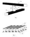
- FIG. 1is a perspective view of a nonvolatile memory cell formed according to a preferred embodiment of the present invention.
- FIG. 2is a perspective view of a portion of a memory level comprising a plurality of the memory cells of FIG. 1 .
- FIG. 3is a perspective view of a memory cell according to the '939 application.
- FIG. 4is a plan view of a dielectric rupture antifuse having a small conductive rupture region formed therethrough.
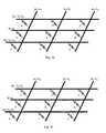
- FIGS. 5 a - 5 dare circuit diagrams illustrating biasing schemes to precondition, reset, set, and read the selected memory cell S without disturbing adjacent half-selected cells H and F and unselected cells U.
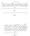
- FIGS. 6 a - 6 dare cross-sectional views illustrating stages in formation of a memory level in a monolithic three dimensional memory array formed according to a preferred embodiment of the present invention.
- a nonvolatile memory cell including a resistivity-switching layer of a metal oxide or nitride compound, the metal oxide or nitride compound including one metalhas been disclosed in Herner et al., U.S. patent application Ser. No. 11/125,939, “Rewriteable Memory Cell Comprising a Diode and a Resistance-Switching Material,” filed May 9, 2005, hereinafter the '939 application and hereby incorporated by reference; and in Herner et al., U.S. patent application Ser. No. 11/395,995, “Nonvolatile Memory Cell Comprising a Diode and a Resistance-Switching Material,” filed Mar. 31, 2006, the '995 application filed on even date herewith.
- the resistivity-switching layeris arranged in series with a diode.
- a data state of the memory cellis stored in the resistivity state of the resistivity-switching layer; i.e. a memory cell having its resistivity-switching layer in a low-resistivity state may correspond to a data ‘0’, while a memory cell having its resistivity-switching layer in a high-resistivity state may correspond to a data ‘1’.
- the resistivity-switching materialis a layer of a metal oxide or nitride compound, the metal oxide or nitride compound including exactly one metal.
- Preferred metal oxide or nitride compoundsinclude Ni x O y , Nb x O y , Ti x O y , Hf x O y , Al x O y , Mg x O y , CO x O y , Cr x O y , V x O y , Zn x O y , Zr x O y , B x N y , and Al x N y , where x and y range between 0 and 1.
- Examplesare the stoichiometric compounds NiO, Nb 2 O 5 , TiO 2 , HfO 2 , Al 2 O 2 , MgO, CoO, CrO 2 , VO, ZnO, ZrO, BN, and AlN, but nonstoichiometric compounds may be used as well.
- a layer of one of these materialsis formed in an initial stable resistivity state, for example a high-resistivity state. That initial resistivity state can be changed to a different stable resistivity state by application of an appropriate electrical pulse.
- a pulse that changes the resistivity-switching layer from a higher-resistivity reset state to a lower-resistivity set stateis a set pulse
- a pulse that changes the resistivity-switching layer from a lower-resistivity state to a higher-resistivity stateis a reset pulse.
- a dielectric rupture antifuseis included in series with the resistivity-switching layer.
- the dielectric rupture antifuseis formed in an initial non-conductive state, impeding current flow.
- the dielectric material of the antifuseUpon application of a programming pulse, the dielectric material of the antifuse suffers dielectric breakdown, altering the dielectric rupture antifuse permanently and causing it to become conductive, permitting increased current flow.
- a diodeis also formed in series with the dielectric rupture antifuse and the resistivity-switching layer.
- dielectric rupture of the antifusetakes place only in a small conductive rupture region. Current is crowded through this rupture region, and this current crowding serves to focus current through a narrow switching path through the resistivity-switching layer, making switching the resistivity of this layer more controllable.
- the dielectric rupture antifuseis ruptured in every cell in a preconditioning step, preferably in the factory, to make the memory ready for use.
- FIG. 1shows a memory cell according to a preferred embodiment of the present invention.
- a pillar 300includes a vertically oriented diode 30 , a resistivity-switching layer 118 , and a dielectric rupture antifuse 117 , disposed in series between a bottom conductor 200 and a top conductor 400 .
- Most embodimentswill include additional layers, serving as barrier layers, adhesion layers, etc., as will be described.
- FIG. 1is one example of a nonvolatile memory cell comprising: a resistance-switching element comprising a layer of a resistivity-switching metal oxide or nitride compound, the metal oxide or nitride compound including only one metal; and a dielectric rupture antifuse.
- a diodemay also be included, the antifuse, resistance-switching element, and antifuse arranged electrically in series. These elements may be disposed between a top and a bottom conductor.
- the diodeis a semiconductor junction diode.
- a semiconductor junction diodeis a semiconductor device with the property of conducting current more easily in one direction than the other, having two terminal electrodes, and made of semiconducting material which is p-type at one electrode and n-type at the other. Examples are p-n diodes, p-i-n diodes, and Zener diodes.
- the diodecan be a Schottky barrier diode, or a diode of metal oxides having semiconductor properties, for example with NiO serving as a p-type region and a TiO 2 serving as the n-type region.
- FIG. 2shows a memory level of such memory cells, which can be formed by forming a plurality of substantially coplanar bottom conductors 200 , pillars 300 , and top conductors 400 .
- This memory levelcan be formed of deposited layers above a substrate, for example a semiconductor wafer substrate, such as a monocrystalline silicon wafer or a silicon-on-insulator wafer.
- a monolithic three dimensional memory arrayis one in which multiple memory levels are formed above a single substrate, such as a wafer, with no intervening substrates.
- the layers forming one memory levelare deposited or grown directly over the layers of an existing level or levels.
- stacked memorieshave been constructed by forming memory levels on separate substrates and adhering the memory levels atop each other, as in Leedy, U.S. Pat. No. 5,915,167, “Three Dimensional Structure Memory.”
- the substratesmay be thinned or removed from the memory levels before bonding, but as the memory levels are initially formed over separate substrates, such memories are not true monolithic three dimensional memory arrays.
- a monolithic three dimensional memory array formed above a substratecomprises at least a first memory level formed at a first height above the substrate and a second memory level formed at a second height different from the first height. Three, four, eight, or indeed any number of memory levels can be formed above the substrate in such a multilevel array.
- Monolithic three dimensional memory arraysare described in Johnson et al., U.S. Pat. No. 6,034,882, “Vertically stacked field programmable nonvolatile memory and method of fabrication”; in Knall et al., U.S. Pat. No. 6,420,215, “Three Dimensional Memory Array and Method of Fabrication”; and in Herner et al., U.S. Pat. No. 6,952,030, “High-density three-dimensional memory cell,” all hereby incorporated by reference.
- preferred materials for the resistivity-switching layerinclude Ni x O y , Nb x O y , Ti x O y , Hf x O y , Al x O y , Mg x O y , Co x O y , V x O y , Zn x O y , Zr x O y , B x N y and Al x N y .
- nickel oxiderefers to both stoichiometric and nonstoichiometric oxides of nickel.
- a layer of nickel oxideis formed in a high-resistivity state. Upon application of a set pulse, the nickel oxide converts to a low-resistivity state.
- FIG. 3in a memory cell with no dielectric rupture antifuse, when a set voltage is applied between top conductor 400 and bottom conductor 200 and current flows through diode 30 , nickel oxide layer 118 is converted from its initial high-resistivity state to a lower-resistivity state.
- a memory cellis described in the '939 application.
- the set and reset pulsesrequire careful control.
- the switch from the set state back to the higher-resistivity reset staterequires that a reset voltage be built up across the resistivity-switching layer.
- a reset voltagebe built up across the resistivity-switching layer.
- dielectric rupture antifuse 117is formed of dielectric material; for example this antifuse may be a single layer of grown or deposited silicon dioxide or some other grown or deposited dielectric. Application of a voltage sufficient to cause dielectric breakdown forms a low-resistance rupture region through the antifuse. Referring to FIG. 4 , the area of this rupture region 42 is much smaller than that of the antifuse 40 itself; it may have a diameter of, for example, about 2-5 nm.
- the dielectric rupture antifuse 117when the dielectric rupture antifuse 117 is adjacent to nickel oxide layer 118 , the current flow is focused through the very narrow rupture region, forming a comparably narrow switching region through nickel oxide layer 118 .
- a thin conductive barrier layer(not shown) may intervene between the nickel oxide layer and the antifuse. If the barrier layer is sufficiently thin (preferably thinner than the resistivity-switching layer) and of relatively high-resistivity material (preferably of resistivity comparable to the high-resistivity state of the resistivity-switching material), the effect of current crowding will be transmitted through the barrier layer.
- resistivity-switching layer 118helps to control the set and reset states. Compared to a similar cell without antifuse layer 117 , in the present invention the current path is higher-resistance at the same voltage, allowing for lower current, thus allowing for lower power.
- the resistivity state of the resistivity-switching layercan readily be set and reset, making for a robust rewriteable memory cell.
- the resistance of the programmed cell during programmingshould be about the same as the sum of the resistance of the circuits driving the wordline and bitline of the selected cell.
- the dielectric regionWhen a low-resistance rupture region is electrically formed by dielectric breakdown across the dielectric layer, the dielectric region is originally high resistance, then drops in resistance as the rupture region forms. As the resistance of the rupture region approaches that of the circuit, the rupture region begins to cool, and will not further increase in size. Thus the formation mechanism of the rupture region tends to cause the rupture region to have about the same resistance as the resistance of the driving circuit. In subsequent programming events, then, the rupture region provides a means to deliver predictable levels of power to the cell.
- Conventional current limiter circuitrymay advantageously be used to control the effective resistance of drivers during programming, as will be well understood by those skilled in the art.
- the initial resistance of the unruptured antifusewill be very high, between about 10 megaOhm and about 1000 megaOhm. After dielectric breakdown, the resistance of the rupture region will be between about 10 kiloOhms and about 1 megaOhm.
- the present inventionallows improved control over set and reset states; thus in some embodiments it will be possible for the nickel oxide (or other resistivity-switching material) to repeatably achieve more than two stable resistivity states which are readily detectable.
- Advantageous methods to set and reset to multiple resistivity levelsare described in the '995 application, filed on even date herewith.
- Circuit structures and methods suitable for use in three dimensional memory arrays formed according to the present inventionare described in Scheuerlein, U.S. patent application Ser. No. 10/403,844, “Word Line Arrangement Having Multi-Layer Word Line Segments for Three-Dimensional Memory Array,” filed Mar. 31, 2003, which is assigned to the assignee of the present invention and is hereby incorporated by reference.
- Beneficial elements of this arrangementinclude use of a common word line driver and very long bitlines allowing reduction in overhead circuitry.
- FIG. 5 aillustrates an advantageous biasing scheme to rupture the antifuse of a selected cell in a preconditioning step to be performed on every cell.
- the diode 30has p-type material adjacent to switching material 118 and antifuse layer 117 , and n-type material adjacent to bottom conductor 200 , which is the wordline.
- the memory cell of FIG. 1can be formed in a memory array (as shown in FIG. 2 ), so wordline 200 is one of many wordlines, and top conductor 400 , which is the bitline, is one of many bitlines. It will further be understood that, for simplicity, antifuses are not depicted in FIGS. 5 a - 5 d.
- the cell to undergo antifuse ruptureis selected cell S at the intersection of selected worldline W 1 and selected bitline B 1 .
- bitline B 1is set to a relatively high preconditioning voltage V P , for example 10 v, while wordline W 1 is set to ground.
- V Pa relatively high preconditioning voltage
- wordline W 1is set to ground.
- This voltage across memory cell Sis sufficient to rupture the antifuse, convert the high-resistivity polysilicon of the diode to a low-resistivity state, and put the nickel oxide resistivity-switching layer into the low-resistivity set state.
- unselected wordlines W 0 and W 2are set to V P -V D volts, where V D is the turn-on voltage of the diode.
- a diodepermits little or no current flow below its turn-on voltage, and permits much higher current flow above the turn-on voltage.
- All unselected bitlinessuch as bitlines B 0 and B 2 , are set to V D .
- Half selected cells H sharing wordline W 1 with selected cell Sare subjected to a positive voltage of V D .
- Unselected cells U sharing neither wordline W 1 or bitline B 1 with selected cell Sare subjected to a voltage of V D ⁇ (V P ⁇ V D ) or a negative voltage of V P -2V D .
- V Pis 10 volts and V D is 0.8 volts.
- Unselected wordlines W 0 and W 2are set to 9.2 volts, and unselected bitlines B 0 and B 2 are set to 0.8 volts.
- Selected cell Ssees 10 volts, half-selected cells H and F are subjected to 0.8 volts, while unselected cells U are subjected to a voltage of ⁇ 8.4 volts.
- selected bitline B 1is set to the reset voltage V R , for example between about 2 and about 4 volts.
- Selected wordline W 1is again at ground, for a voltage of V R volts across selected cell S.
- Unselected wordlines W 0 and W 2are set to V R -V D
- unselected bitlines B 0 and B 2are set to V D .
- selected cell Sis subjected to V R
- half selected cells H and Fare subjected to a voltage of V D
- a voltage of V D ⁇ (V R ⁇ V D )is applied to unselected cells U.
- V Ris 3 volts and V D is 0.8 volts.
- Selected bitline B 1is at 3 volts and selected wordline W 0 is at ground.
- Unselected wordlines W 0 and W 2are at 2.2 volts, while unselected bitlines B 0 and B 2 are at 0.8 volts.
- the voltage across selected cell Sis 3 volts
- across half-selected cells H and Fis 0.8 volts
- Uis ⁇ 1.4 v.
- selected bitline B 1is set to the set voltage V S , for example between about 4.1 and about 7 volts.
- Selected wordline W 1is again at ground, for a voltage of V S volts across selected cell S.
- Unselected wordlines W 0 and W 2are set to V S -V D
- unselected bitlines B 0 and B 2are set to V D .
- V Sthe voltage across selected cell S
- half selected cells H and Fare subjected to a voltage of V D
- a voltage of V D ⁇ (V S ⁇ V D )is applied to unselected cells U.
- V Sis 6 volts and V D is 0.8 volts.
- Selected bitline B 1is at 6 volts and selected wordline W 1 is at ground.
- Unselected wordlines W 0 and W 2are at 5.2 volts, while unselected bitlines B 0 and B 2 are at 0.8 volts.
- the voltage across selected cell Sis 6 volts, across half-selected cells H and F is 0.8 volts, and across unselected cells U is ⁇ 4.4 volts.
- V RDa read voltage
- V RDRead voltage
- Selected bitline B 1is set to V RD
- selected wordline W 1is again at ground, for a voltage of V RD volts across selected cell S.
- Unselected wordlines W 0 and W 2are set to V RD
- unselected bitlines B 0 and B 2are set to V D .
- half selected cells Hare subjected to a voltage of V D
- a voltage of V D -V RDis applied to unselected cells U.
- Half-selected cells Fare subjected to approximately zero bias to ensure accurate sensing of selected cell S.
- V RDis 1.8 volts and V D is 0.8 volts.
- Selected bitline B 1is at 1.8 volts and selected wordline W 1 is at ground.
- Unselected wordlines W 0 and W 2are at 1.8 volts, while unselected bitlines B 0 and B 2 are at 0.8 volts.
- the voltage across selected cell Sis 1.8 volts
- across half-selected cells His 0.8 volts
- across unselected cells Uis ⁇ 1.0 volts
- across half-selected cells Fis approximately zero volts.
- a preconditioning pulseis applied, wherein the preconditioning pulse serves to rupture the dielectric rupture antifuse, forming a low-resistance rupture region through the dielectric rupture antifuse, and wherein the preconditioning pulse serves to form a resistivity-switching region in the layer of resistivity-switching metal oxide or nitride compound, changing the resistivity state of the resistivity-switching region.
- the switching regionis in a low-resistivity state, and next a first reset pulse is applied to put the switching region in a high-resistivity reset state.
- the cellcan be further programmed: After the first reset pulse, a first programming set pulse may be applied to put the switching region in a programmed set state wherein a first data state of the memory cell is stored in a resistivity state of the switching region.
- the cellcan also be programmed with new values, or erased: After the first programming set pulse, a first programming reset pulse can be applied to put the switching region in a programmed reset state, wherein a second data state of the memory cell is stored in the resistivity state of the switching region, and so forth.
- an array formed according the present inventionmay comprise a first memory cell wherein a first dielectric rupture antifuse of the first memory cell is ruptured, and wherein a first resistance-switching memory element of the first memory cell is in a low-resistance state; and a second memory cell wherein a second dielectric rupture antifuse of the second memory cell is ruptured, and wherein a second resistance-switching memory element of the second memory cell is in a high-resistance state.
- the second memory elementmay have a resistance at least three times higher than a resistance of the first memory element.
- an array formed according to the present inventionmay include a first memory cell wherein a first dielectric rupture antifuse of the first memory cell is ruptured and wherein a first resistance-switching memory element of the first memory cell is in a first resistance state; a second memory cell wherein a second dielectric rupture antifuse of the second memory cell is ruptured and wherein a second resistance-switching memory element of the second memory cell is in a second resistance state different from the first resistance state; and a third memory cell wherein a third dielectric rupture antifuse of the third memory cell is ruptured and wherein a third resistance-switching memory element of the third memory cell is in a third resistance state different from the first resistance state and the second resistance state, wherein the first, second, and third resistance states are detectably different and correspond to first, second, and third data states.
- a detailed examplewill be provided of fabrication of a monolithic three dimensional memory array formed according to a preferred embodiment of the present invention. For clarity many details, including steps, materials, and process conditions, will be included. It will be understood that this example is non-limiting, and that these details can be modified, omitted, or augmented while the results fall within the scope of the invention.
- This substrate 100can be any semiconducting substrate as known in the art, such as monocrystalline silicon, IV-IV compounds like silicon-germanium or silicon-germanium-carbon, III-V compounds, II-VII compounds, epitaxial layers over such substrates, or any other semiconducting material.
- the substratemay include integrated circuits fabricated therein.
- the insulating layer 102is formed over substrate 100 .
- the insulating layer 102can be silicon oxide, silicon nitride, high-dielectric film, Si—C—O—H film, or any other suitable insulating material.
- the first conductors 200are formed over the substrate 100 and insulator 102 .
- An adhesion layer 104may be included between the insulating layer 102 and the conducting layer 106 .
- a preferred material for the adhesion layer 104is titanium nitride, though other materials may be used, or this layer may be omitted.
- Adhesion layer 104can be deposited by any conventional method, for example by sputtering.
- the thickness of adhesion layer 104can range from about 20 to about 500 angstroms, and is preferably between about 100 and about 400 angstroms, most preferably about 200 angstroms. Note that in this discussion, “thickness” will denote vertical thickness, measured in a direction perpendicular to substrate 100 .
- Conducting layer 106can comprise any conducting material known in the art, such as doped semiconductor, metals such as tungsten, or conductive metal silicides; in a preferred embodiment, conducting layer 106 is tungsten.
- the layerswill be patterned and etched using any suitable masking and etching process to form substantially parallel, substantially coplanar conductors 200 , shown in FIG. 6 a in cross-section.
- photoresistis deposited, patterned by photolithography and the layers etched, and then the photoresist removed, using standard process techniques such as “ashing” in an oxygen-containing plasma, and strip of remaining polymers formed during etch in a conventional liquid solvent such as those formulated by EKC.
- Dielectric material 108can be any known electrically insulating material, such as silicon oxide, silicon nitride, or silicon oxynitride.
- silicon oxideis used as dielectric material 108 .
- the silicon oxidecan be deposited using any known process, such as chemical vapor deposition (CVD), or, for example, high-density plasma CVD (HDPCVD).
- planar surface 109is shown in FIG. 6 a .
- This removal of dielectric overfill to form planar surface 109can be performed by any process known in the art, such as etchback or chemical mechanical polishing (CMP).
- CMPchemical mechanical polishing
- the etchback techniques described in Raghuram et al., U.S. application Ser. No. 10/883417, “Nonselective Unpatterned Etchback to Expose Buried Patterned Features,” filed Jun. 30, 2004 and hereby incorporated by reference in its entirety,can advantageously be used.
- conductor railscan be formed by a damascene process, in which oxide is deposited, trenches are etched in the oxide, then the trenches are filled with conductive material to create the conductor rails.
- a barrier layer 110preferably of titanium nitride, is deposited on planar surface 109 to prevent tungsten of conductive layer 106 from contacting silicon in the diode to be deposited and subsequent formation of tungsten silicide, which may damage the diode.
- Semiconductor material that will be patterned into pillarsis deposited.
- the semiconductor materialcan be, for example, silicon, germanium, or alloys of silicon and/or germanium.
- semiconductor metal oxidessuch as nickel oxide as a p-type semiconductor or titanium oxide as an n-type semiconductor, may be used.
- the present examplewill describe the use of silicon, though it will be understood that other materials may be used instead.
- the semiconductor pillarcomprises a junction diode, the junction diode comprising a bottom heavily doped region of a first conductivity type and a top heavily doped region of a second conductivity type.
- the middle region, between the top and bottom regions,is an intrinsic or lightly doped region of either the first or second conductivity type.
- bottom heavily doped region 112is heavily doped n-type silicon.
- heavily doped region 112is deposited and doped with an n-type dopant such as phosphorus by any conventional method, preferably by in situ doping. This layer is preferably between about 200 and about 800 angstroms.
- the silicon that will form the remainder of the diodeis deposited.
- a subsequent planarization stepwill remove some silicon, so an extra thickness is deposited. If the planarization step is performed using a conventional CMP method, about 800 angstroms of thickness may be lost (this is an average; the amount varies across the wafer. Depending on the slurry and methods used during CMP, the silicon loss may be more or less.) If the planarization step is performed by an etchback method, only about 400 angstroms of silicon or less may be removed.
- between about 800 and about 4000 angstroms of undoped siliconis deposited by any conventional method; preferably between about 1500 and about 2500 angstroms; most preferably between about 1800 and about 2200 angstroms. If desired, the silicon can be lightly doped.
- Pillars 300should have about the same pitch and about the same width as conductors 200 below, such that each pillar 300 is formed on top of a conductor 200 . Some misalignment can be tolerated.
- the pillars 300can be formed using any suitable masking and etching process.
- photoresistcan be deposited, patterned using standard photolithography techniques, and etched, then the photoresist removed.
- a hard mask of some other materialfor example silicon dioxide, can be formed on top of the semiconductor layer stack, with bottom antireflective coating (BARC) on top, then patterned and etched.
- BARCbottom antireflective coating
- DARCdielectric antireflective coating
- Dielectric material 108is deposited over and between pillars 300 , filling the gaps between them.
- Dielectric material 108can be any known electrically insulating material, such as silicon dioxide.
- the dielectric material on top of the pillars 300is removed, exposing the tops of pillars 300 separated by dielectric material 108 , and leaving a substantially planar surface.
- This removal of dielectric overfill and planarizationcan be performed by any process known in the art, such as CMP or etchback.
- CMPchemical vapor deposition
- etchbackthe etchback techniques described in Raghuram et al. can be used.
- heavily doped top regions 116are formed at this point by ion implantation with a p-type dopant, for example boron or BF 2 .
- a p-type dopantfor example boron or BF 2 .
- the resulting structureis shown in FIG. 6 b .
- the diode described hereinhas a bottom n-type region 112 and a top p-type region 116 . If preferred, the conductivity types could be reversed. If desired, p-i-n diodes having an n-region on the bottom could be used in one memory level while p-i-n diodes having a p-type region on the bottom could be used in another memory level.
- the diodeis formed by a method comprising depositing a semiconductor layerstack of silicon, germanium, or an alloy of silicon or germanium; and patterning and etching the layerstack to form a vertically oriented pillar. Gaps between the diodes are filled with dielectric and dielectric overfill removed.
- antifuse 117is a layer of a dielectric material such as silicon oxide, silicon nitride, or silicon oxynitride, preferably silicon dioxide.
- a silicon dioxide layercan be grown by oxidation of silicon layer 116 , for example.
- an oxide which is grown (by oxidation, for example, by consuming some silicon from the underlying layer) rather than depositedwill be denser, and have fewer defects, and be higher quality than a comparable deposited dielectric.
- dielectrics having a high K valuesuch as Si 3 N 4 or Al 2 O 3 , may be preferred.
- layer 121 of a conductive barrier materialfor example titanium nitride, a metal, or some other appropriate material, may be deposited.
- the thickness of layer 121may be between about 25 and about 200 angstroms, preferably about 50 angstroms.
- layer 121is a high-resistivity, low-density titanium nitride formed by ionized metal plasma deposition of titanium nitride with no applied self-bias, as described in Herner, U.S. Pat. No. 6,956,278, “Low-Density, High-Resistivity Titanium Nitride Layer for Use as a Contact for Low-Leakage Dielectric Layers,” filed Jun. 30, 2003, and hereby incorporated by reference.
- this titanium nitridemay have a resistivity greater than about 300 microOhm-cms and a density less than about 4.25 grams per cubic cm.
- layer 121may be omitted.
- a layer 118 of a metal oxide or nitride resistance-switching materialis deposited on barrier layer 121 , or if barrier layer 121 was omitted, this layer is deposited directly on antifuse 117 .
- Layer 118is preferably between about 50 and about 400 angstroms thick.
- Layer 118can be any of the materials described earlier, and is preferably formed of a metal oxide or nitride having including exactly one metal which exhibits resistance switching behavior; preferably a material selected from the group consisting of Ni x O y , Nb x O y , Ti x O y , Hf x O y , Al x O y , Mg x O y , Co x O y , Cr x O y , V x O y , Zn x O y , Zr x O y , B x N y , and Al x N y .
- Ni x O y , Nb x O yTi x O y , Hf x O y , Al x O y , Mg x O y , Co x O y , Cr x O y , V x O y , Zn x O y , Zr x O y
- adding a metal to the resistivity-switching metal oxide or nitride compoundhas been effective in reducing the set and reset voltages required to switch a resistivity-switching layer of the metal oxide or nitride compound between stable resistivity states.
- a metalmay be added to the metal oxide or nitride compound of layer 118 .
- Preferred metalsinclude cobalt, aluminum, gallium, indium, nickel, niobium, zirconium, titanium, hafnium, tantalum, magnesium, chromium, vanadium, boron, yttrium, and lanthanum.
- the metal additiveis between about 0.01 and about 5 percent of the metal atoms in the layer of metal oxide or nitride compound.
- barrier layer 123is deposited on nickel oxide layer 118 .
- Layer 123is preferably titanium nitride, though some other appropriate conductive barrier material may be used instead. In some embodiments, layer 123 may be omitted.
- Layers 123 , 118 , and 121are patterned and etched to form short pillars, ideally directly on top of pillars 300 formed in the previous pattern and etch step. Some misalignment may occur, as shown in FIG. 6 c , and can be tolerated.
- the photomask used to pattern pillars 300may be reused in this patterning step.
- barrier layer 121 , nickel oxide layer 118 , and optionally barrier layer 123can be formed before (and therefore beneath) diode layers 112 , 114 , and 116 , and may be patterned in the same or in a separate patterning step.
- antifuse layer 117is formed between nickel oxide layer 118 and the diode layers.
- a dielectric material 108is deposited over and between the short etched pillars including layers 123 , 118 , and 121 , and a planarizing step, for example by CMP, removes overfill, exposing the top layer of the short pillars at a planarized surface.
- top conductors 400a conductive material or stack is deposited to form the top conductors 400 .
- titanium nitride barrier layer 120is deposited next, followed by tungsten layer 124 .
- Top conductors 400can be patterned and etched in the same manner as bottom conductors 200 . Overlying second conductors 400 will preferably extend in a different direction from first conductors 200 , preferably substantially perpendicular to them. Each pillar 300 should be formed at the intersection of a top conductor 400 and a bottom conductor 200 . Some misalignment may be tolerated.
- a dielectric material(not shown) is deposited over and between conductors 400 . The resulting structure, shown in FIG. 6 d , is a bottom or first story of memory cells.
- Additional memory levelscan be formed above this first memory level.
- conductorscan be shared between memory levels; i.e. top conductor 400 would serve as the bottom conductor of the next memory level.
- an interlevel dielectricis formed above the first memory level of FIG. 6 d , its surface planarized, and construction of a second memory level begins on this planarized interlevel dielectric, with no shared conductors.
- An anneal stepcrystallizes the silicon to polysilicon. This anneal may be done as a single step after fabrication of the memory levels is complete, or the temperatures required to grow the antifuse by thermal oxidation may be sufficient to crystallize the semiconductor material, and a separate anneal may not be required.
- Photomasksare used during photolithography to pattern each layer. Certain layers are repeated in each memory level, and the photomasks used to form them may be reused. For example, a photomask defining the pillars 300 of FIG. 6 d may be reused for each memory level. Each photomask includes reference marks used to properly align it. When a photomask is reused, reference marks formed in a second or subsequent use may interfere with the same reference marks formed during a prior use of the same photomask. Chen et al., U.S. patent application Ser. No. 11/097,496, “Masking of Repeated Overlay and Alignment Marks to Allow Reuse of Photomasks in a Vertical Structure,” filed Mar. 31, 2005, and hereby incorporated by reference, describes a method to avoid such interference during the formation of a monolithic three dimensional memory array like that of the present invention.
- the circuitryis adapted to program each memory cell to one, two, three, or more programmed values, and erase it, multiple times.
- a monolithic three dimensional memory arraycomprising: i) a first memory level monolithically formed above a substrate, the first memory level comprising: a) a plurality of substantially parallel, substantially coplanar first conductors; b) a plurality of substantially parallel, substantially coplanar second conductors above the first conductors; and c) a first plurality of memory cells, each memory cell comprising a dielectric rupture antifuse, a portion of one of the bottom conductors, and a portion of one of the top conductors, a layer of a resistivity-switching metal oxide or nitride compound, wherein the metal oxide or nitride compound includes only one metal, and wherein the dielectric rupture antifuse and the layer of resistivity-switching metal oxide or nitride are arranged electrically in series between the portion of the top conductor and the portion of the bottom conductor, and ii) a second memory level monolithically formed above the first
- the resistivity-switching layermay be above the diode, as in FIG. 1 , or below.
- the resistivity-switching layermay be part of a pillar, as in FIG. 1 . Recall, however, that resistivity switching will take place only in a narrow switching region where current flows. If the resistivity-switching material is formed in a relatively high-resistivity state, it may be formed as part of the top conductor or the bottom conductor; the higher resistivity of the non-switching region will prevent adjacent cells from being shorted together.
- the antifusecan be, for example, either above or below the resistivity-switching layer.
- the antifuseshould be very close to the resistivity-switching layer, however; preferably either immediately adjacent to it or with only a thin barrier layer intervening.
- the resistivity-switching layer and the diodeare both formed in a vertically oriented pillar, as in FIG. 1 , the resistivity-switching layer and the diode may be formed in a single patterning step, or in separate patterning steps.
- the diodein a very small array, may be omitted and the memory cell can include only a resistivity-switching layer and an antifuse in series between conductors.
Landscapes
- Engineering & Computer Science (AREA)
- Chemical & Material Sciences (AREA)
- Materials Engineering (AREA)
- Manufacturing & Machinery (AREA)
- Semiconductor Memories (AREA)
- Design And Manufacture Of Integrated Circuits (AREA)
Abstract
Description
Claims (31)
Priority Applications (7)
| Application Number | Priority Date | Filing Date | Title |
|---|---|---|---|
| US11/395,421US7829875B2 (en) | 2006-03-31 | 2006-03-31 | Nonvolatile rewritable memory cell comprising a resistivity-switching oxide or nitride and an antifuse |
| PCT/US2007/007153WO2007126678A1 (en) | 2006-03-31 | 2007-03-22 | Nonvolatile rewriteable memory cell comprising a resistivity- switching oxide or nitride and an antifuse |
| KR1020087026474AKR20090006839A (en) | 2006-03-31 | 2007-03-22 | Nonvolatile Rewritable Memory Cells with Resistivity-Switching Oxide or Nitride and Antifuse |
| CN2007800121076ACN101416252B (en) | 2006-03-31 | 2007-03-22 | Method for programming nonvolatile memory cell |
| EP07753755AEP2002444A1 (en) | 2006-03-31 | 2007-03-22 | Nonvolatile rewriteable memory cell comprising a resistivity- switching oxide or nitride and an antifuse |
| JP2009502873AJP2009535793A (en) | 2006-03-31 | 2007-03-22 | Nonvolatile rewritable memory cell containing resistivity switching oxide or nitride and antifuse |
| TW096110614ATWI348757B (en) | 2006-03-31 | 2007-03-27 | Nonvolatile rewriteable memory cell comprising a resistivity-switching oxide or nitride and an antifuse |
Applications Claiming Priority (1)
| Application Number | Priority Date | Filing Date | Title |
|---|---|---|---|
| US11/395,421US7829875B2 (en) | 2006-03-31 | 2006-03-31 | Nonvolatile rewritable memory cell comprising a resistivity-switching oxide or nitride and an antifuse |
Publications (2)
| Publication Number | Publication Date |
|---|---|
| US20070228354A1 US20070228354A1 (en) | 2007-10-04 |
| US7829875B2true US7829875B2 (en) | 2010-11-09 |
Family
ID=38420527
Family Applications (1)
| Application Number | Title | Priority Date | Filing Date |
|---|---|---|---|
| US11/395,421Active2028-02-10US7829875B2 (en) | 2006-03-31 | 2006-03-31 | Nonvolatile rewritable memory cell comprising a resistivity-switching oxide or nitride and an antifuse |
Country Status (7)
| Country | Link |
|---|---|
| US (1) | US7829875B2 (en) |
| EP (1) | EP2002444A1 (en) |
| JP (1) | JP2009535793A (en) |
| KR (1) | KR20090006839A (en) |
| CN (1) | CN101416252B (en) |
| TW (1) | TWI348757B (en) |
| WO (1) | WO2007126678A1 (en) |
Cited By (84)
| Publication number | Priority date | Publication date | Assignee | Title |
|---|---|---|---|---|
| US20090236747A1 (en)* | 2008-03-19 | 2009-09-24 | Semiconductor Technology Academic Research Center | Semiconductor device and method for fabricating the same |
| US20100123210A1 (en)* | 2008-11-18 | 2010-05-20 | Seagate Technology Llc | Asymmetric barrier diode |
| US20100221874A1 (en)* | 2005-05-06 | 2010-09-02 | Taiwan Semiconductor Manufacturing Company, Ltd. | Method for Multi-Level Interconnection Memory Device |
| US20110317470A1 (en)* | 2010-06-24 | 2011-12-29 | The Regents Of The University Of Michigan | Rectification element and method for resistive switching for non volatile memory device |
| US8158964B2 (en) | 2009-07-13 | 2012-04-17 | Seagate Technology Llc | Schottky diode switch and memory units containing the same |
| US8258020B2 (en) | 2010-11-04 | 2012-09-04 | Crossbar Inc. | Interconnects for stacked non-volatile memory device and method |
| US20120248397A1 (en)* | 2009-10-27 | 2012-10-04 | Canon Anelva Corporation | Nonvolatile storage element and manufacturing method thereof |
| WO2013015776A1 (en)* | 2011-07-22 | 2013-01-31 | Crossbar, Inc. | Seed layer for a p + silicon germanium material for a non-volatile memory device and method |
| US8374018B2 (en) | 2010-07-09 | 2013-02-12 | Crossbar, Inc. | Resistive memory using SiGe material |
| US8391049B2 (en) | 2010-09-29 | 2013-03-05 | Crossbar, Inc. | Resistor structure for a non-volatile memory device and method |
| US8394670B2 (en) | 2011-05-31 | 2013-03-12 | Crossbar, Inc. | Vertical diodes for non-volatile memory device |
| US8404553B2 (en) | 2010-08-23 | 2013-03-26 | Crossbar, Inc. | Disturb-resistant non-volatile memory device and method |
| US8441835B2 (en) | 2010-06-11 | 2013-05-14 | Crossbar, Inc. | Interface control for improved switching in RRAM |
| US20130119337A1 (en)* | 2010-06-13 | 2013-05-16 | Peking University | Resistive-switching device capable of implementing multiary addition operation and method for multiary addition operation |
| US8450710B2 (en) | 2011-05-27 | 2013-05-28 | Crossbar, Inc. | Low temperature p+ silicon junction material for a non-volatile memory device |
| US8450209B2 (en) | 2010-11-05 | 2013-05-28 | Crossbar, Inc. | p+ Polysilicon material on aluminum for non-volatile memory device and method |
| US8467227B1 (en) | 2010-11-04 | 2013-06-18 | Crossbar, Inc. | Hetero resistive switching material layer in RRAM device and method |
| US8492195B2 (en) | 2010-08-23 | 2013-07-23 | Crossbar, Inc. | Method for forming stackable non-volatile resistive switching memory devices |
| US8519485B2 (en) | 2010-06-11 | 2013-08-27 | Crossbar, Inc. | Pillar structure for memory device and method |
| US8558212B2 (en) | 2010-09-29 | 2013-10-15 | Crossbar, Inc. | Conductive path in switching material in a resistive random access memory device and control |
| US8648426B2 (en) | 2010-12-17 | 2014-02-11 | Seagate Technology Llc | Tunneling transistors |
| US8659929B2 (en) | 2011-06-30 | 2014-02-25 | Crossbar, Inc. | Amorphous silicon RRAM with non-linear device and operation |
| US8658476B1 (en) | 2012-04-20 | 2014-02-25 | Crossbar, Inc. | Low temperature P+ polycrystalline silicon material for non-volatile memory device |
| WO2014047590A1 (en)* | 2012-09-24 | 2014-03-27 | Crossbar, Inc. | Electrode structure for a non-volatile memory device and method |
| US8697533B2 (en) | 2010-10-27 | 2014-04-15 | Crossbar, Inc. | Method for obtaining smooth, continuous silver film |
| US8716098B1 (en) | 2012-03-09 | 2014-05-06 | Crossbar, Inc. | Selective removal method and structure of silver in resistive switching device for a non-volatile memory device |
| US8741772B2 (en) | 2012-02-16 | 2014-06-03 | Intermolecular, Inc. | In-situ nitride initiation layer for RRAM metal oxide switching material |
| US8765566B2 (en) | 2012-05-10 | 2014-07-01 | Crossbar, Inc. | Line and space architecture for a non-volatile memory device |
| US8791010B1 (en) | 2010-12-31 | 2014-07-29 | Crossbar, Inc. | Silver interconnects for stacked non-volatile memory device and method |
| US8796102B1 (en) | 2012-08-29 | 2014-08-05 | Crossbar, Inc. | Device structure for a RRAM and method |
| US8796658B1 (en) | 2012-05-07 | 2014-08-05 | Crossbar, Inc. | Filamentary based non-volatile resistive memory device and method |
| US8809831B2 (en) | 2010-07-13 | 2014-08-19 | Crossbar, Inc. | On/off ratio for non-volatile memory device and method |
| US8815696B1 (en) | 2010-12-31 | 2014-08-26 | Crossbar, Inc. | Disturb-resistant non-volatile memory device using via-fill and etchback technique |
| US8841196B1 (en) | 2010-09-29 | 2014-09-23 | Crossbar, Inc. | Selective deposition of silver for non-volatile memory device fabrication |
| US8853099B2 (en) | 2011-12-16 | 2014-10-07 | Intermolecular, Inc. | Nonvolatile resistive memory element with a metal nitride containing switching layer |
| US8884261B2 (en) | 2010-08-23 | 2014-11-11 | Crossbar, Inc. | Device switching using layered device structure |
| US8889521B1 (en) | 2012-09-14 | 2014-11-18 | Crossbar, Inc. | Method for silver deposition for a non-volatile memory device |
| US8930174B2 (en) | 2010-12-28 | 2015-01-06 | Crossbar, Inc. | Modeling technique for resistive random access memory (RRAM) cells |
| US8934280B1 (en) | 2013-02-06 | 2015-01-13 | Crossbar, Inc. | Capacitive discharge programming for two-terminal memory cells |
| US8946669B1 (en) | 2012-04-05 | 2015-02-03 | Crossbar, Inc. | Resistive memory device and fabrication methods |
| US8947908B2 (en) | 2010-11-04 | 2015-02-03 | Crossbar, Inc. | Hetero-switching layer in a RRAM device and method |
| US8946667B1 (en) | 2012-04-13 | 2015-02-03 | Crossbar, Inc. | Barrier structure for a silver based RRAM and method |
| US8946673B1 (en) | 2012-08-24 | 2015-02-03 | Crossbar, Inc. | Resistive switching device structure with improved data retention for non-volatile memory device and method |
| US8946046B1 (en) | 2012-05-02 | 2015-02-03 | Crossbar, Inc. | Guided path for forming a conductive filament in RRAM |
| US8982647B2 (en) | 2012-11-14 | 2015-03-17 | Crossbar, Inc. | Resistive random access memory equalization and sensing |
| US9012307B2 (en) | 2010-07-13 | 2015-04-21 | Crossbar, Inc. | Two terminal resistive switching device structure and method of fabricating |
| US9070859B1 (en) | 2012-05-25 | 2015-06-30 | Crossbar, Inc. | Low temperature deposition method for polycrystalline silicon material for a non-volatile memory device |
| US9087576B1 (en) | 2012-03-29 | 2015-07-21 | Crossbar, Inc. | Low temperature fabrication method for a three-dimensional memory device and structure |
| US9112145B1 (en) | 2013-01-31 | 2015-08-18 | Crossbar, Inc. | Rectified switching of two-terminal memory via real time filament formation |
| US9153623B1 (en) | 2010-12-31 | 2015-10-06 | Crossbar, Inc. | Thin film transistor steering element for a non-volatile memory device |
| US9191000B2 (en) | 2011-07-29 | 2015-11-17 | Crossbar, Inc. | Field programmable gate array utilizing two-terminal non-volatile memory |
| US9324942B1 (en) | 2013-01-31 | 2016-04-26 | Crossbar, Inc. | Resistive memory cell with solid state diode |
| US9401475B1 (en) | 2010-08-23 | 2016-07-26 | Crossbar, Inc. | Method for silver deposition for a non-volatile memory device |
| US9406379B2 (en) | 2013-01-03 | 2016-08-02 | Crossbar, Inc. | Resistive random access memory with non-linear current-voltage relationship |
| US9412790B1 (en) | 2012-12-04 | 2016-08-09 | Crossbar, Inc. | Scalable RRAM device architecture for a non-volatile memory device and method |
| US9460788B2 (en) | 2014-07-09 | 2016-10-04 | Crossbar, Inc. | Non-volatile memory cell utilizing volatile switching two terminal device and a MOS transistor |
| US9520557B2 (en) | 2008-10-20 | 2016-12-13 | The Regents Of The University Of Michigan | Silicon based nanoscale crossbar memory |
| US9543359B2 (en) | 2011-05-31 | 2017-01-10 | Crossbar, Inc. | Switching device having a non-linear element |
| US9564587B1 (en) | 2011-06-30 | 2017-02-07 | Crossbar, Inc. | Three-dimensional two-terminal memory with enhanced electric field and segmented interconnects |
| US9570678B1 (en) | 2010-06-08 | 2017-02-14 | Crossbar, Inc. | Resistive RAM with preferental filament formation region and methods |
| US9576616B2 (en) | 2012-10-10 | 2017-02-21 | Crossbar, Inc. | Non-volatile memory with overwrite capability and low write amplification |
| US9583701B1 (en) | 2012-08-14 | 2017-02-28 | Crossbar, Inc. | Methods for fabricating resistive memory device switching material using ion implantation |
| USRE46335E1 (en) | 2010-11-04 | 2017-03-07 | Crossbar, Inc. | Switching device having a non-linear element |
| US9601692B1 (en) | 2010-07-13 | 2017-03-21 | Crossbar, Inc. | Hetero-switching layer in a RRAM device and method |
| US9601690B1 (en) | 2011-06-30 | 2017-03-21 | Crossbar, Inc. | Sub-oxide interface layer for two-terminal memory |
| US9620206B2 (en) | 2011-05-31 | 2017-04-11 | Crossbar, Inc. | Memory array architecture with two-terminal memory cells |
| US9627443B2 (en) | 2011-06-30 | 2017-04-18 | Crossbar, Inc. | Three-dimensional oblique two-terminal memory with enhanced electric field |
| US9627057B2 (en) | 2013-03-15 | 2017-04-18 | Crossbar, Inc. | Programming two-terminal memory cells with reduced program current |
| US9633723B2 (en) | 2011-06-23 | 2017-04-25 | Crossbar, Inc. | High operating speed resistive random access memory |
| US9633724B2 (en) | 2014-07-07 | 2017-04-25 | Crossbar, Inc. | Sensing a non-volatile memory device utilizing selector device holding characteristics |
| US9685608B2 (en) | 2012-04-13 | 2017-06-20 | Crossbar, Inc. | Reduced diffusion in metal electrode for two-terminal memory |
| US9685483B2 (en) | 2014-07-09 | 2017-06-20 | Crossbar, Inc. | Selector-based non-volatile cell fabrication utilizing IC-foundry compatible process |
| US9698201B2 (en) | 2014-07-09 | 2017-07-04 | Crossbar, Inc. | High density selector-based non volatile memory cell and fabrication |
| US9729155B2 (en) | 2011-07-29 | 2017-08-08 | Crossbar, Inc. | Field programmable gate array utilizing two-terminal non-volatile memory |
| US9735358B2 (en) | 2012-08-14 | 2017-08-15 | Crossbar, Inc. | Noble metal / non-noble metal electrode for RRAM applications |
| US9741765B1 (en) | 2012-08-14 | 2017-08-22 | Crossbar, Inc. | Monolithically integrated resistive memory using integrated-circuit foundry compatible processes |
| US9761635B1 (en) | 2014-03-11 | 2017-09-12 | Crossbar, Inc. | Selector device for two-terminal memory |
| US9768234B2 (en) | 2014-05-20 | 2017-09-19 | Crossbar, Inc. | Resistive memory architecture and devices |
| US10056907B1 (en) | 2011-07-29 | 2018-08-21 | Crossbar, Inc. | Field programmable gate array utilizing two-terminal non-volatile memory |
| US10096362B1 (en) | 2017-03-24 | 2018-10-09 | Crossbar, Inc. | Switching block configuration bit comprising a non-volatile memory cell |
| US10115819B2 (en) | 2015-05-29 | 2018-10-30 | Crossbar, Inc. | Recessed high voltage metal oxide semiconductor transistor for RRAM cell |
| US10211397B1 (en) | 2014-07-07 | 2019-02-19 | Crossbar, Inc. | Threshold voltage tuning for a volatile selection device |
| US10290801B2 (en) | 2014-02-07 | 2019-05-14 | Crossbar, Inc. | Scalable silicon based resistive memory device |
| US11068620B2 (en) | 2012-11-09 | 2021-07-20 | Crossbar, Inc. | Secure circuit integrated with memory layer |
Families Citing this family (45)
| Publication number | Priority date | Publication date | Assignee | Title |
|---|---|---|---|---|
| US7812404B2 (en)* | 2005-05-09 | 2010-10-12 | Sandisk 3D Llc | Nonvolatile memory cell comprising a diode and a resistance-switching material |
| US7834338B2 (en)* | 2005-11-23 | 2010-11-16 | Sandisk 3D Llc | Memory cell comprising nickel-cobalt oxide switching element |
| US7816659B2 (en) | 2005-11-23 | 2010-10-19 | Sandisk 3D Llc | Devices having reversible resistivity-switching metal oxide or nitride layer with added metal |
| KR101176542B1 (en)* | 2006-03-02 | 2012-08-24 | 삼성전자주식회사 | Nonvolatile memory device and memory array |
| US7808810B2 (en)* | 2006-03-31 | 2010-10-05 | Sandisk 3D Llc | Multilevel nonvolatile memory cell comprising a resistivity-switching oxide or nitride and an antifuse |
| US7875871B2 (en)* | 2006-03-31 | 2011-01-25 | Sandisk 3D Llc | Heterojunction device comprising a semiconductor and a resistivity-switching oxide or nitride |
| KR101239962B1 (en)* | 2006-05-04 | 2013-03-06 | 삼성전자주식회사 | Variable resistive memory device comprising buffer layer on lower electrode |
| KR101206036B1 (en)* | 2006-11-16 | 2012-11-28 | 삼성전자주식회사 | Resistive random access memory enclosing a transition metal solid solution and Manufacturing Method for the same |
| US7704789B2 (en)* | 2007-02-05 | 2010-04-27 | Intermolecular, Inc. | Methods for forming resistive switching memory elements |
| US7678607B2 (en)* | 2007-02-05 | 2010-03-16 | Intermolecular, Inc. | Methods for forming resistive switching memory elements |
| US7972897B2 (en)* | 2007-02-05 | 2011-07-05 | Intermolecular, Inc. | Methods for forming resistive switching memory elements |
| US7629198B2 (en)* | 2007-03-05 | 2009-12-08 | Intermolecular, Inc. | Methods for forming nonvolatile memory elements with resistive-switching metal oxides |
| US8097878B2 (en)* | 2007-03-05 | 2012-01-17 | Intermolecular, Inc. | Nonvolatile memory elements with metal-deficient resistive-switching metal oxides |
| US8975613B1 (en) | 2007-05-09 | 2015-03-10 | Intermolecular, Inc. | Resistive-switching memory elements having improved switching characteristics |
| CN101711431B (en)* | 2007-05-09 | 2015-11-25 | 分子间公司 | Resistive non-volatile memory element |
| US8173989B2 (en)* | 2007-05-30 | 2012-05-08 | Samsung Electronics Co., Ltd. | Resistive random access memory device and methods of manufacturing and operating the same |
| US7846785B2 (en)* | 2007-06-29 | 2010-12-07 | Sandisk 3D Llc | Memory cell that employs a selectively deposited reversible resistance-switching element and methods of forming the same |
| US7824956B2 (en) | 2007-06-29 | 2010-11-02 | Sandisk 3D Llc | Memory cell that employs a selectively grown reversible resistance-switching element and methods of forming the same |
| US7902537B2 (en) | 2007-06-29 | 2011-03-08 | Sandisk 3D Llc | Memory cell that employs a selectively grown reversible resistance-switching element and methods of forming the same |
| US8233308B2 (en)* | 2007-06-29 | 2012-07-31 | Sandisk 3D Llc | Memory cell that employs a selectively deposited reversible resistance-switching element and methods of forming the same |
| JP5501966B2 (en) | 2007-07-25 | 2014-05-28 | インターモレキュラー, インコーポレイテッド | Multi-state non-volatile memory device |
| US8294219B2 (en)* | 2007-07-25 | 2012-10-23 | Intermolecular, Inc. | Nonvolatile memory element including resistive switching metal oxide layers |
| KR20090029558A (en)* | 2007-09-18 | 2009-03-23 | 삼성전자주식회사 | Diodes and memory elements comprising them |
| US8343813B2 (en)* | 2009-04-10 | 2013-01-01 | Intermolecular, Inc. | Resistive-switching memory elements having improved switching characteristics |
| US8183553B2 (en)* | 2009-04-10 | 2012-05-22 | Intermolecular, Inc. | Resistive switching memory element including doped silicon electrode |
| US7960216B2 (en)* | 2008-05-10 | 2011-06-14 | Intermolecular, Inc. | Confinement techniques for non-volatile resistive-switching memories |
| US7961494B2 (en) | 2008-04-11 | 2011-06-14 | Sandisk 3D Llc | Non-volatile multi-level re-writable memory cell incorporating a diode in series with multiple resistors and method for writing same |
| US8129704B2 (en)* | 2008-05-01 | 2012-03-06 | Intermolecular, Inc. | Non-volatile resistive-switching memories |
| US7977152B2 (en)* | 2008-05-10 | 2011-07-12 | Intermolecular, Inc. | Non-volatile resistive-switching memories formed using anodization |
| US8305793B2 (en)* | 2008-05-16 | 2012-11-06 | Qimonda Ag | Integrated circuit with an array of resistance changing memory cells |
| US8008096B2 (en)* | 2008-06-05 | 2011-08-30 | Intermolecular, Inc. | ALD processing techniques for forming non-volatile resistive-switching memories |
| US8049305B1 (en) | 2008-10-16 | 2011-11-01 | Intermolecular, Inc. | Stress-engineered resistance-change memory device |
| US8420478B2 (en)* | 2009-03-31 | 2013-04-16 | Intermolecular, Inc. | Controlled localized defect paths for resistive memories |
| US8072795B1 (en) | 2009-10-28 | 2011-12-06 | Intermolecular, Inc. | Biploar resistive-switching memory with a single diode per memory cell |
| KR20110074354A (en) | 2009-12-24 | 2011-06-30 | 삼성전자주식회사 | Memory device and its operation method |
| US8487292B2 (en)* | 2010-03-16 | 2013-07-16 | Sandisk 3D Llc | Resistance-switching memory cell with heavily doped metal oxide layer |
| US8395926B2 (en) | 2010-06-18 | 2013-03-12 | Sandisk 3D Llc | Memory cell with resistance-switching layers and lateral arrangement |
| US8724369B2 (en) | 2010-06-18 | 2014-05-13 | Sandisk 3D Llc | Composition of memory cell with resistance-switching layers |
| US8520425B2 (en) | 2010-06-18 | 2013-08-27 | Sandisk 3D Llc | Resistive random access memory with low current operation |
| WO2013019228A1 (en)* | 2011-08-03 | 2013-02-07 | Hewlett-Packard Development Company, L.P. | Nitride-based memristors |
| JP5684104B2 (en) | 2011-12-27 | 2015-03-11 | 株式会社東芝 | Method for manufacturing metal bridge type memory device |
| TWI452689B (en)* | 2012-01-17 | 2014-09-11 | Winbond Electronics Corp | Nonvolatile memory device and array thereof |
| US8592250B2 (en)* | 2012-02-01 | 2013-11-26 | International Business Machines Corporation | Self-aligned process to fabricate a memory cell array with a surrounding-gate access transistor |
| CN105679785B (en)* | 2016-01-18 | 2018-11-27 | 苏州大学 | RRAM device based on multilayer boron nitride and preparation method thereof |
| US11042432B1 (en) | 2019-12-20 | 2021-06-22 | Western Digital Technologies, Inc. | Data storage device with dynamic stripe length manager |
Citations (115)
| Publication number | Priority date | Publication date | Assignee | Title |
|---|---|---|---|---|
| US2655609A (en) | 1952-07-22 | 1953-10-13 | Bell Telephone Labor Inc | Bistable circuits, including transistors |
| US2971140A (en) | 1959-01-07 | 1961-02-07 | Marc A Chappey | Two-terminal semi-conductor devices having negative differential resistance |
| GB1284645A (en) | 1970-01-30 | 1972-08-09 | Welwyn Electric Ltd | Then film device |
| US3796926A (en) | 1971-03-29 | 1974-03-12 | Ibm | Bistable resistance device which does not require forming |
| GB1416644A (en) | 1972-06-05 | 1975-12-03 | Ibm | Electrical device incorporating a film of a n |
| US4204028A (en) | 1978-03-16 | 1980-05-20 | Ppg Industries, Inc. | Conductive metal oxide film for solar energy control |
| US4499557A (en) | 1980-10-28 | 1985-02-12 | Energy Conversion Devices, Inc. | Programmable cell for use in programmable electronic arrays |
| US4646266A (en) | 1984-09-28 | 1987-02-24 | Energy Conversion Devices, Inc. | Programmable semiconductor structures and methods for using the same |
| US4772571A (en) | 1984-09-14 | 1988-09-20 | Stc Plc | Process of self aligned nitridation of TiSi2 to form TiN/TiSi2 contact |
| US4907054A (en) | 1987-11-10 | 1990-03-06 | Thomson-Csf | Matrix of photosensitive elements combining a phototransistor with a storage capacitor |
| US4940553A (en) | 1988-05-26 | 1990-07-10 | Deutsche Automobilgesellschaft | Aqueous nickel hydroxide paste of high flowability |
| US5037200A (en) | 1989-07-11 | 1991-08-06 | Tosoh Corporation | Laser-operated detector |
| US5166758A (en) | 1991-01-18 | 1992-11-24 | Energy Conversion Devices, Inc. | Electrically erasable phase change memory |
| US5273915A (en) | 1992-10-05 | 1993-12-28 | Motorola, Inc. | Method for fabricating bipolar junction and MOS transistors on SOI |
| US5311055A (en) | 1991-11-22 | 1994-05-10 | The United States Of America As Represented By The Secretary Of The Navy | Trenched bipolar transistor structures |
| US5774394A (en) | 1997-05-22 | 1998-06-30 | Motorola, Inc. | Magnetic memory cell with increased GMR ratio |
| US5854102A (en) | 1996-03-01 | 1998-12-29 | Micron Technology, Inc. | Vertical diode structures with low series resistance |
| US5876788A (en) | 1997-01-16 | 1999-03-02 | International Business Machines Corporation | High dielectric TiO2 -SiN composite films for memory applications |
| US5915167A (en) | 1997-04-04 | 1999-06-22 | Elm Technology Corporation | Three dimensional structure memory |
| US6034882A (en) | 1998-11-16 | 2000-03-07 | Matrix Semiconductor, Inc. | Vertically stacked field programmable nonvolatile memory and method of fabrication |
| USRE37259E1 (en) | 1996-04-19 | 2001-07-03 | Energy Conversion Devices, Inc. | Multibit single cell memory element having tapered contact |
| WO2001069655A2 (en) | 2000-03-14 | 2001-09-20 | Isis Innovation Limited | Spin transistor |
| US6369431B1 (en) | 1996-02-23 | 2002-04-09 | Micron Technology, Inc. | Method for forming conductors in semiconductor devices |
| US20020057594A1 (en) | 2000-11-01 | 2002-05-16 | Tadahiko Hirai | Magnetic memory and information recording and reproducing method therefor |
| US6420215B1 (en) | 2000-04-28 | 2002-07-16 | Matrix Semiconductor, Inc. | Three-dimensional memory array and method of fabrication |
| US6426891B1 (en) | 1999-10-27 | 2002-07-30 | Sony Corporation | Nonvolatile memory with a two-terminal switching element and its driving method |
| US6465370B1 (en) | 1998-06-26 | 2002-10-15 | Infineon Technologies Ag | Low leakage, low capacitance isolation material |
| US6483734B1 (en) | 2001-11-26 | 2002-11-19 | Hewlett Packard Company | Memory device having memory cells capable of four states |
| US20030013007A1 (en) | 2001-07-13 | 2003-01-16 | Kaun Thomas D. | Cell structure for electrochemical devices and method of making same |
| US20030047727A1 (en) | 2001-09-07 | 2003-03-13 | Chien Chiang | Using selective deposition to form phase-change memory cells |
| US6534841B1 (en) | 2001-12-14 | 2003-03-18 | Hewlett-Packard Company | Continuous antifuse material in memory structure |
| US6541792B1 (en)* | 2001-09-14 | 2003-04-01 | Hewlett-Packard Development Company, Llp | Memory device having dual tunnel junction memory cells |
| US20030081446A1 (en) | 2001-10-31 | 2003-05-01 | Peter Fricke | Memory cell structure |
| EP1308960A2 (en) | 2001-10-31 | 2003-05-07 | Hewlett-Packard Company | Feedback write method for programmable memory |
| US6618295B2 (en) | 2001-03-21 | 2003-09-09 | Matrix Semiconductor, Inc. | Method and apparatus for biasing selected and unselected array lines when writing a memory array |
| WO2003079463A2 (en) | 2002-03-15 | 2003-09-25 | Axon Technologies Corporation | Programmable structure, an array including the structure, and methods of forming the same |
| US20040002186A1 (en) | 2002-06-27 | 2004-01-01 | Vyvoda Michael A. | Electrically isolated pillars in active devices |
| US20040084743A1 (en) | 2002-11-04 | 2004-05-06 | Vanbuskirk Michael A. | Control of memory arrays utilizing zener diode-like devices |
| US20040095300A1 (en) | 2002-11-20 | 2004-05-20 | Osram Opto Semiconductors Gmbh | Current limiting device |
| US6753561B1 (en) | 2002-08-02 | 2004-06-22 | Unity Semiconductor Corporation | Cross point memory array using multiple thin films |
| US6761985B2 (en) | 2000-10-05 | 2004-07-13 | Battelle Memorial Institute | Magnetic transparent conducting oxide film and method of making |
| US6774458B2 (en)* | 2002-07-23 | 2004-08-10 | Hewlett Packard Development Company, L.P. | Vertical interconnection structure and methods |
| US6778441B2 (en) | 2001-08-30 | 2004-08-17 | Micron Technology, Inc. | Integrated circuit memory device and method |
| US20040161888A1 (en) | 2002-08-02 | 2004-08-19 | Unity Semiconductor Corporation | Multi-resistive state material that uses dopants |
| US20040160818A1 (en) | 2002-08-02 | 2004-08-19 | Unity Semiconductor Corporation | Cross point memory array using multiple modes of operation |
| US20040160804A1 (en) | 2002-08-02 | 2004-08-19 | Unity Semiconductor Corporation | Memory array of a non-volatile ram |
| US20040160807A1 (en) | 2002-08-02 | 2004-08-19 | Unity Semiconductor Corporation | Cross point memory array with memory plugs exhibiting a characteristic hysteresis |
| US20040159867A1 (en) | 2002-08-02 | 2004-08-19 | Unity Semiconductor Corporation | Multi-layer conductive memory device |
| US20040160817A1 (en) | 2002-08-02 | 2004-08-19 | Unity Semiconductor Corporation | Non-volatile memory with a single transistor and resistive memory element |
| US20040160808A1 (en) | 2002-08-02 | 2004-08-19 | Unity Semiconductor Corporation | Cross point memory array using distinct voltages |
| US20040159869A1 (en) | 2002-08-02 | 2004-08-19 | Unity Semiconductor Corporation | Memory array with high temperature wiring |
| US20040159828A1 (en) | 2002-08-02 | 2004-08-19 | Unity Semiconductor, Inc. | Resistive memory device with a treated interface |
| US20040160798A1 (en) | 2002-10-31 | 2004-08-19 | Unity Semiconductor Inc. | Adaptive programming technique for a re-writable conductive memory device |
| US20040160805A1 (en) | 2002-08-02 | 2004-08-19 | Unity Semiconductor Corporation | Multi-output multiplexor |
| US20040160806A1 (en) | 2002-08-02 | 2004-08-19 | Unity Semiconductor Corporation | Providing a reference voltage to a cross point memory array |
| US20040160819A1 (en) | 2002-08-02 | 2004-08-19 | Unity Semiconductor Corporation | High-density NVRAM |
| US20040160812A1 (en) | 2002-08-02 | 2004-08-19 | Unity Semiconductor Corporation | 2-Terminal trapped charge memory device with voltage switchable multi-level resistance |
| US20040170040A1 (en) | 2002-08-02 | 2004-09-02 | Unity Semiconductor Corporation | Rewritable memory with non-linear memory element |
| US6787401B2 (en) | 1996-03-01 | 2004-09-07 | Micron Technology, Inc. | Method of making vertical diode structures |
| US6815744B1 (en) | 1999-02-17 | 2004-11-09 | International Business Machines Corporation | Microelectronic device for storing information with switchable ohmic resistance |
| US20040228172A1 (en) | 2002-08-02 | 2004-11-18 | Unity Semiconductor Corporation | Conductive memory stack with sidewall |
| EP1484799A2 (en) | 2003-06-03 | 2004-12-08 | Samsung Electronics Co., Ltd. | Nonvolatile memory device comprising a switching device and a resistant material and method of manufacturing the same |
| US6836421B2 (en) | 2002-08-02 | 2004-12-28 | Unity Semiconductor Corporation | Line drivers that fit within a specified line pitch |
| US6850455B2 (en) | 2002-08-02 | 2005-02-01 | Unity Semiconductor Corporation | Multiplexor having a reference voltage on unselected lines |
| US20050045919A1 (en) | 2003-08-27 | 2005-03-03 | Nec Corporation | Semiconductor device |
| EP1513159A2 (en) | 2003-09-03 | 2005-03-09 | The Regents Of The University Of California | Memory devices based on electric field programmable films |
| US20050052915A1 (en) | 2002-12-19 | 2005-03-10 | Matrix Semiconductor, Inc. | Nonvolatile memory cell without a dielectric antifuse having high- and low-impedance states |
| WO2005024839A1 (en) | 2003-09-11 | 2005-03-17 | Infineon Technologies Ag | Storage location having an ionic conduction storage mechanism and method for the production thereof |
| US6879505B2 (en) | 2003-03-31 | 2005-04-12 | Matrix Semiconductor, Inc. | Word line arrangement having multi-layer word line segments for three-dimensional memory array |
| US20050167699A1 (en) | 2003-10-23 | 2005-08-04 | Matsushita Electric Industrial Co., Ltd. | Variable resistance element, method of manufacturing the element, memory containing the element, and method of driving the memory |
| US6946719B2 (en) | 2003-12-03 | 2005-09-20 | Matrix Semiconductor, Inc | Semiconductor device including junction diode contacting contact-antifuse unit comprising silicide |
| US6952030B2 (en) | 2002-12-19 | 2005-10-04 | Matrix Semiconductor, Inc. | High-density three-dimensional memory cell |
| US20050221200A1 (en) | 2004-04-01 | 2005-10-06 | Matrix Semiconductor, Inc. | Photomask features with chromeless nonprinting phase shifting window |
| US6956278B2 (en) | 2003-06-30 | 2005-10-18 | Matrix Semiconductor, Inc. | Low-density, high-resistivity titanium nitride layer for use as a contact for low-leakage dielectric layers |
| US20050247921A1 (en) | 2004-04-28 | 2005-11-10 | Samsung Electronics Co., Ltd. | Memory device using multi-layer with a graded resistance change |
| US20050286211A1 (en) | 2004-05-18 | 2005-12-29 | Cay-Uwe Pinnow | Solid electrolyte switching element |
| US20060006495A1 (en) | 2002-12-19 | 2006-01-12 | Matrix Semiconductor, Inc. | Ultrathin chemically grown oxide film as a dopant diffusion barrier in semiconductor devices |
| US20060067117A1 (en) | 2004-09-29 | 2006-03-30 | Matrix Semiconductor, Inc. | Fuse memory cell comprising a diode, the diode serving as the fuse element |
| US20060094236A1 (en) | 2004-11-03 | 2006-05-04 | Elkins Patricia C | Electroless plating of metal caps for chalcogenide-based memory devices |
| US20060098472A1 (en) | 2004-11-10 | 2006-05-11 | Seung-Eon Ahn | Nonvolatile memory device, array of nonvolatile memory devices, and methods of making the same |
| US20060128153A1 (en) | 2004-12-14 | 2006-06-15 | Matrix Semiconductor, Inc. | Method for cleaning slurry particles from a surface polished by chemical mechanical polishing |
| US20060157679A1 (en) | 2005-01-19 | 2006-07-20 | Matrix Semiconductor, Inc. | Structure and method for biasing phase change memory array for reliable writing |
| US20060164880A1 (en) | 2003-07-18 | 2006-07-27 | Toshitsugu Sakamoto | Switching element method of driving switching element rewritable logic integrated circuit and memory |
| WO2006078505A2 (en) | 2005-01-19 | 2006-07-27 | Matrix Semiconductor, Inc. | A non-volatile memory cell comprising a dielectric layer and a phase change material in series |
| US20060250837A1 (en) | 2005-05-09 | 2006-11-09 | Sandisk 3D, Llc | Nonvolatile memory cell comprising a diode and a resistance-switching material |
| US20060250836A1 (en) | 2005-05-09 | 2006-11-09 | Matrix Semiconductor, Inc. | Rewriteable memory cell comprising a diode and a resistance-switching material |
| US20060268594A1 (en) | 2003-03-18 | 2006-11-30 | Haruki Toda | Programmable resistance memory device |
| US20060273298A1 (en) | 2005-06-02 | 2006-12-07 | Matrix Semiconductor, Inc. | Rewriteable memory cell comprising a transistor and resistance-switching material in series |
| WO2007004843A1 (en) | 2005-07-04 | 2007-01-11 | Industry-University Cooperation Foundation Hanyang University | Method for forming multi-layered binary oxide film for use in resistance random access memory |
| US20070010100A1 (en) | 2005-07-11 | 2007-01-11 | Matrix Semiconductor, Inc. | Method of plasma etching transition metals and their compounds |
| US7172840B2 (en) | 2003-12-05 | 2007-02-06 | Sandisk Corporation | Photomask features with interior nonprinting window using alternating phase shifting |
| US7176064B2 (en) | 2003-12-03 | 2007-02-13 | Sandisk 3D Llc | Memory cell comprising a semiconductor junction diode crystallized adjacent to a silicide |
| US20070072360A1 (en) | 2005-09-28 | 2007-03-29 | Tanmay Kumar | Method for using a memory cell comprising switchable semiconductor memory element with trimmable resistance |
| US7215564B2 (en) | 2004-04-27 | 2007-05-08 | Infineon Technologies Ag | Semiconductor memory component in cross-point architecture |
| US20070114509A1 (en) | 2005-11-23 | 2007-05-24 | Sandisk 3D Llc | Memory cell comprising nickel-cobalt oxide switching element |
| US20070114508A1 (en) | 2005-11-23 | 2007-05-24 | Matrix Semiconductor, Inc. | Reversible resistivity-switching metal oxide or nitride layer with added metal |
| US7224013B2 (en) | 2004-09-29 | 2007-05-29 | Sandisk 3D Llc | Junction diode comprising varying semiconductor compositions |
| WO2007067448A1 (en) | 2005-12-09 | 2007-06-14 | Sandisk 3D Llc | Deposited semiconductor structure to minimize n-type dopant diffusion and method of making |
| WO2007072308A1 (en) | 2005-12-20 | 2007-06-28 | Koninklijke Philips Electronics N.V. | A vertical phase change memory cell and methods for manufacturing thereof |
| US7238607B2 (en) | 2002-12-19 | 2007-07-03 | Sandisk 3D Llc | Method to minimize formation of recess at surface planarized by chemical mechanical planarization |
| US20070228414A1 (en) | 2006-03-31 | 2007-10-04 | Sandisk 3D, Llc | Heterojunction device comprising a semiconductor and a resistivity-switching oxide or nitride |
| US20070236981A1 (en) | 2006-03-31 | 2007-10-11 | Sandisk 3D, Llc | Multilevel nonvolatile memory cell comprising a resistivity-switching oxide or nitride and an antifuse |
| US7285464B2 (en) | 2002-12-19 | 2007-10-23 | Sandisk 3D Llc | Nonvolatile memory cell comprising a reduced height vertical diode |
| US20070246743A1 (en) | 2006-04-21 | 2007-10-25 | Sung-Lae Cho | Method of forming a phase change material layer, method of forming a phase change memory device using the same, and a phase change memory device so formed |
| EP1914806A1 (en) | 2005-08-05 | 2008-04-23 | Sharp Kabushiki Kaisha | Variable resistor element and production method therefor and storage device provided with it |
| US7391064B1 (en) | 2004-12-01 | 2008-06-24 | Spansion Llc | Memory device with a selection element and a control line in a substantially similar layer |
| US20080175032A1 (en) | 2007-01-23 | 2008-07-24 | Kabushiki Kaisha Toshiba | Semiconductor memory and method for manufacturing the same |
| US20090001343A1 (en) | 2007-06-29 | 2009-01-01 | April Schricker | Memory cell that employs a selectively deposited reversible resistance-switching element and methods of forming the same |
| US20090001342A1 (en) | 2007-06-29 | 2009-01-01 | April Schricker | Memory cell that employs a selectively grown reversible resistance-switching element and methods of forming the same |
| US20090001344A1 (en) | 2007-06-29 | 2009-01-01 | April Schricker | Memory cell that employs a selectively grown reversible resistance-switching element and methods of forming the same |
| US20090001345A1 (en) | 2007-06-29 | 2009-01-01 | April Schricker | Memory cell that employs a selectively deposited reversible resistance-switching element and methods of forming the same |
| US7501331B2 (en) | 2006-03-31 | 2009-03-10 | Sandisk 3D Llc | Low-temperature metal-induced crystallization of silicon-germanium films |
| US20090104756A1 (en) | 2007-06-29 | 2009-04-23 | Tanmay Kumar | Method to form a rewriteable memory cell comprising a diode and a resistivity-switching grown oxide |
| US7553611B2 (en) | 2005-03-31 | 2009-06-30 | Sandisk 3D Llc | Masking of repeated overlay and alignment marks to allow reuse of photomasks in a vertical structure |
| US20090236581A1 (en) | 2006-11-30 | 2009-09-24 | Fujitsu Limited | Resistance memory element, method of manufacturing resistance memory element and semiconductor memory device |
Family Cites Families (10)
| Publication number | Priority date | Publication date | Assignee | Title |
|---|---|---|---|---|
| US739064A (en)* | 1900-07-23 | 1903-09-15 | Kitson Hydrocarbon Heating And Incandescent Lighting Company | Hydrocarbon incandescent lamp. |
| JPH09210130A (en)* | 1996-02-07 | 1997-08-12 | Honda Motor Co Ltd | Fixing structure of tubular member to shaft member |
| US6224013B1 (en)* | 1998-08-27 | 2001-05-01 | Lockheed Martin Corporation | Tail fin deployment device |
| JP4047531B2 (en)* | 2000-10-17 | 2008-02-13 | 株式会社東芝 | Ferroelectric memory device |
| JP3597163B2 (en)* | 2001-10-22 | 2004-12-02 | 沖電気工業株式会社 | Readout method and readout circuit for ferroelectric memory cell |
| US20030189851A1 (en)* | 2002-04-09 | 2003-10-09 | Brandenberger Sarah M. | Non-volatile, multi-level memory device |
| US6798985B2 (en)* | 2002-04-30 | 2004-09-28 | Albert A. Reff | Camera system including a camera mounting apparatus for obtaining close-up photographs |
| US20040197947A1 (en)* | 2003-04-07 | 2004-10-07 | Fricke Peter J. | Memory-cell filament electrodes and methods |
| JP4338545B2 (en)* | 2004-02-19 | 2009-10-07 | 富士通株式会社 | Capacitor sheet |
| US7964867B2 (en)* | 2004-12-28 | 2011-06-21 | Nec Corporation | Switching element, switching element fabriction method, reconfigurable logic integrated circuit, and memory element |
- 2006
- 2006-03-31USUS11/395,421patent/US7829875B2/enactiveActive
- 2007
- 2007-03-22CNCN2007800121076Apatent/CN101416252B/ennot_activeExpired - Fee Related
- 2007-03-22JPJP2009502873Apatent/JP2009535793A/enactivePending
- 2007-03-22EPEP07753755Apatent/EP2002444A1/ennot_activeWithdrawn
- 2007-03-22WOPCT/US2007/007153patent/WO2007126678A1/enactiveApplication Filing
- 2007-03-22KRKR1020087026474Apatent/KR20090006839A/ennot_activeCeased
- 2007-03-27TWTW096110614Apatent/TWI348757B/ennot_activeIP Right Cessation
Patent Citations (132)
| Publication number | Priority date | Publication date | Assignee | Title |
|---|---|---|---|---|
| US2655609A (en) | 1952-07-22 | 1953-10-13 | Bell Telephone Labor Inc | Bistable circuits, including transistors |
| US2971140A (en) | 1959-01-07 | 1961-02-07 | Marc A Chappey | Two-terminal semi-conductor devices having negative differential resistance |
| GB1284645A (en) | 1970-01-30 | 1972-08-09 | Welwyn Electric Ltd | Then film device |
| US3796926A (en) | 1971-03-29 | 1974-03-12 | Ibm | Bistable resistance device which does not require forming |
| GB1416644A (en) | 1972-06-05 | 1975-12-03 | Ibm | Electrical device incorporating a film of a n |
| US4204028A (en) | 1978-03-16 | 1980-05-20 | Ppg Industries, Inc. | Conductive metal oxide film for solar energy control |
| US4499557A (en) | 1980-10-28 | 1985-02-12 | Energy Conversion Devices, Inc. | Programmable cell for use in programmable electronic arrays |
| US4772571A (en) | 1984-09-14 | 1988-09-20 | Stc Plc | Process of self aligned nitridation of TiSi2 to form TiN/TiSi2 contact |
| US4646266A (en) | 1984-09-28 | 1987-02-24 | Energy Conversion Devices, Inc. | Programmable semiconductor structures and methods for using the same |
| US4907054A (en) | 1987-11-10 | 1990-03-06 | Thomson-Csf | Matrix of photosensitive elements combining a phototransistor with a storage capacitor |
| US4940553A (en) | 1988-05-26 | 1990-07-10 | Deutsche Automobilgesellschaft | Aqueous nickel hydroxide paste of high flowability |
| US5037200A (en) | 1989-07-11 | 1991-08-06 | Tosoh Corporation | Laser-operated detector |
| US5166758A (en) | 1991-01-18 | 1992-11-24 | Energy Conversion Devices, Inc. | Electrically erasable phase change memory |
| US5311055A (en) | 1991-11-22 | 1994-05-10 | The United States Of America As Represented By The Secretary Of The Navy | Trenched bipolar transistor structures |
| US5273915A (en) | 1992-10-05 | 1993-12-28 | Motorola, Inc. | Method for fabricating bipolar junction and MOS transistors on SOI |
| US6369431B1 (en) | 1996-02-23 | 2002-04-09 | Micron Technology, Inc. | Method for forming conductors in semiconductor devices |
| US5854102A (en) | 1996-03-01 | 1998-12-29 | Micron Technology, Inc. | Vertical diode structures with low series resistance |
| US6787401B2 (en) | 1996-03-01 | 2004-09-07 | Micron Technology, Inc. | Method of making vertical diode structures |
| USRE37259E1 (en) | 1996-04-19 | 2001-07-03 | Energy Conversion Devices, Inc. | Multibit single cell memory element having tapered contact |
| US5876788A (en) | 1997-01-16 | 1999-03-02 | International Business Machines Corporation | High dielectric TiO2 -SiN composite films for memory applications |
| US5915167A (en) | 1997-04-04 | 1999-06-22 | Elm Technology Corporation | Three dimensional structure memory |
| US5774394A (en) | 1997-05-22 | 1998-06-30 | Motorola, Inc. | Magnetic memory cell with increased GMR ratio |
| US6465370B1 (en) | 1998-06-26 | 2002-10-15 | Infineon Technologies Ag | Low leakage, low capacitance isolation material |
| US6034882A (en) | 1998-11-16 | 2000-03-07 | Matrix Semiconductor, Inc. | Vertically stacked field programmable nonvolatile memory and method of fabrication |
| US6815744B1 (en) | 1999-02-17 | 2004-11-09 | International Business Machines Corporation | Microelectronic device for storing information with switchable ohmic resistance |
| US6426891B1 (en) | 1999-10-27 | 2002-07-30 | Sony Corporation | Nonvolatile memory with a two-terminal switching element and its driving method |
| US20030209971A1 (en) | 2000-02-11 | 2003-11-13 | Kozicki Michael N. | Programmable structure, an array including the structure, and methods of forming the same |
| WO2001069655A2 (en) | 2000-03-14 | 2001-09-20 | Isis Innovation Limited | Spin transistor |
| US6420215B1 (en) | 2000-04-28 | 2002-07-16 | Matrix Semiconductor, Inc. | Three-dimensional memory array and method of fabrication |
| US6761985B2 (en) | 2000-10-05 | 2004-07-13 | Battelle Memorial Institute | Magnetic transparent conducting oxide film and method of making |
| US20020057594A1 (en) | 2000-11-01 | 2002-05-16 | Tadahiko Hirai | Magnetic memory and information recording and reproducing method therefor |
| US6618295B2 (en) | 2001-03-21 | 2003-09-09 | Matrix Semiconductor, Inc. | Method and apparatus for biasing selected and unselected array lines when writing a memory array |
| US20030013007A1 (en) | 2001-07-13 | 2003-01-16 | Kaun Thomas D. | Cell structure for electrochemical devices and method of making same |
| US6778441B2 (en) | 2001-08-30 | 2004-08-17 | Micron Technology, Inc. | Integrated circuit memory device and method |
| US20030047727A1 (en) | 2001-09-07 | 2003-03-13 | Chien Chiang | Using selective deposition to form phase-change memory cells |
| US6541792B1 (en)* | 2001-09-14 | 2003-04-01 | Hewlett-Packard Development Company, Llp | Memory device having dual tunnel junction memory cells |
| EP1308960A2 (en) | 2001-10-31 | 2003-05-07 | Hewlett-Packard Company | Feedback write method for programmable memory |
| US20030081446A1 (en) | 2001-10-31 | 2003-05-01 | Peter Fricke | Memory cell structure |
| US6707698B2 (en)* | 2001-10-31 | 2004-03-16 | Hewlett-Packard Development Company, L.P. | Dual memory cell |
| US6483734B1 (en) | 2001-11-26 | 2002-11-19 | Hewlett Packard Company | Memory device having memory cells capable of four states |
| US6534841B1 (en) | 2001-12-14 | 2003-03-18 | Hewlett-Packard Company | Continuous antifuse material in memory structure |
| WO2003079463A2 (en) | 2002-03-15 | 2003-09-25 | Axon Technologies Corporation | Programmable structure, an array including the structure, and methods of forming the same |
| US20040002186A1 (en) | 2002-06-27 | 2004-01-01 | Vyvoda Michael A. | Electrically isolated pillars in active devices |
| US6774458B2 (en)* | 2002-07-23 | 2004-08-10 | Hewlett Packard Development Company, L.P. | Vertical interconnection structure and methods |
| US6834008B2 (en) | 2002-08-02 | 2004-12-21 | Unity Semiconductor Corporation | Cross point memory array using multiple modes of operation |
| US6850455B2 (en) | 2002-08-02 | 2005-02-01 | Unity Semiconductor Corporation | Multiplexor having a reference voltage on unselected lines |
| US20040160818A1 (en) | 2002-08-02 | 2004-08-19 | Unity Semiconductor Corporation | Cross point memory array using multiple modes of operation |
| US20040160804A1 (en) | 2002-08-02 | 2004-08-19 | Unity Semiconductor Corporation | Memory array of a non-volatile ram |
| US20040160807A1 (en) | 2002-08-02 | 2004-08-19 | Unity Semiconductor Corporation | Cross point memory array with memory plugs exhibiting a characteristic hysteresis |
| US20040159867A1 (en) | 2002-08-02 | 2004-08-19 | Unity Semiconductor Corporation | Multi-layer conductive memory device |
| US20040160817A1 (en) | 2002-08-02 | 2004-08-19 | Unity Semiconductor Corporation | Non-volatile memory with a single transistor and resistive memory element |
| US20040160808A1 (en) | 2002-08-02 | 2004-08-19 | Unity Semiconductor Corporation | Cross point memory array using distinct voltages |
| US20040159869A1 (en) | 2002-08-02 | 2004-08-19 | Unity Semiconductor Corporation | Memory array with high temperature wiring |
| US20040159828A1 (en) | 2002-08-02 | 2004-08-19 | Unity Semiconductor, Inc. | Resistive memory device with a treated interface |
| US20040161888A1 (en) | 2002-08-02 | 2004-08-19 | Unity Semiconductor Corporation | Multi-resistive state material that uses dopants |
| US20040160805A1 (en) | 2002-08-02 | 2004-08-19 | Unity Semiconductor Corporation | Multi-output multiplexor |
| US20040160806A1 (en) | 2002-08-02 | 2004-08-19 | Unity Semiconductor Corporation | Providing a reference voltage to a cross point memory array |
| US20040160819A1 (en) | 2002-08-02 | 2004-08-19 | Unity Semiconductor Corporation | High-density NVRAM |
| US20040160812A1 (en) | 2002-08-02 | 2004-08-19 | Unity Semiconductor Corporation | 2-Terminal trapped charge memory device with voltage switchable multi-level resistance |
| US20040170040A1 (en) | 2002-08-02 | 2004-09-02 | Unity Semiconductor Corporation | Rewritable memory with non-linear memory element |
| US6753561B1 (en) | 2002-08-02 | 2004-06-22 | Unity Semiconductor Corporation | Cross point memory array using multiple thin films |
| US6798685B2 (en) | 2002-08-02 | 2004-09-28 | Unity Semiconductor Corporation | Multi-output multiplexor |
| US6870755B2 (en) | 2002-08-02 | 2005-03-22 | Unity Semiconductor Corporation | Re-writable memory with non-linear memory element |
| US20040228172A1 (en) | 2002-08-02 | 2004-11-18 | Unity Semiconductor Corporation | Conductive memory stack with sidewall |
| US6859382B2 (en) | 2002-08-02 | 2005-02-22 | Unity Semiconductor Corporation | Memory array of a non-volatile ram |
| US6856536B2 (en) | 2002-08-02 | 2005-02-15 | Unity Semiconductor Corporation | Non-volatile memory with a single transistor and resistive memory element |
| US6831854B2 (en) | 2002-08-02 | 2004-12-14 | Unity Semiconductor Corporation | Cross point memory array using distinct voltages |
| US6850429B2 (en) | 2002-08-02 | 2005-02-01 | Unity Semiconductor Corporation | Cross point memory array with memory plugs exhibiting a characteristic hysteresis |
| US6836421B2 (en) | 2002-08-02 | 2004-12-28 | Unity Semiconductor Corporation | Line drivers that fit within a specified line pitch |
| US20040160798A1 (en) | 2002-10-31 | 2004-08-19 | Unity Semiconductor Inc. | Adaptive programming technique for a re-writable conductive memory device |
| US20040084743A1 (en) | 2002-11-04 | 2004-05-06 | Vanbuskirk Michael A. | Control of memory arrays utilizing zener diode-like devices |
| US20040095300A1 (en) | 2002-11-20 | 2004-05-20 | Osram Opto Semiconductors Gmbh | Current limiting device |
| US20060006495A1 (en) | 2002-12-19 | 2006-01-12 | Matrix Semiconductor, Inc. | Ultrathin chemically grown oxide film as a dopant diffusion barrier in semiconductor devices |
| US6952030B2 (en) | 2002-12-19 | 2005-10-04 | Matrix Semiconductor, Inc. | High-density three-dimensional memory cell |
| US7238607B2 (en) | 2002-12-19 | 2007-07-03 | Sandisk 3D Llc | Method to minimize formation of recess at surface planarized by chemical mechanical planarization |
| US20050052915A1 (en) | 2002-12-19 | 2005-03-10 | Matrix Semiconductor, Inc. | Nonvolatile memory cell without a dielectric antifuse having high- and low-impedance states |
| US7265049B2 (en) | 2002-12-19 | 2007-09-04 | Sandisk 3D Llc | Ultrathin chemically grown oxide film as a dopant diffusion barrier in semiconductor devices |
| US7285464B2 (en) | 2002-12-19 | 2007-10-23 | Sandisk 3D Llc | Nonvolatile memory cell comprising a reduced height vertical diode |
| US20060268594A1 (en) | 2003-03-18 | 2006-11-30 | Haruki Toda | Programmable resistance memory device |
| US6879505B2 (en) | 2003-03-31 | 2005-04-12 | Matrix Semiconductor, Inc. | Word line arrangement having multi-layer word line segments for three-dimensional memory array |
| EP1484799A2 (en) | 2003-06-03 | 2004-12-08 | Samsung Electronics Co., Ltd. | Nonvolatile memory device comprising a switching device and a resistant material and method of manufacturing the same |
| US20040245557A1 (en) | 2003-06-03 | 2004-12-09 | Samsung Electronics Co., Ltd. | Nonvolatile memory device comprising one switching device and one resistant material and method of manufacturing the same |
| US6956278B2 (en) | 2003-06-30 | 2005-10-18 | Matrix Semiconductor, Inc. | Low-density, high-resistivity titanium nitride layer for use as a contact for low-leakage dielectric layers |
| US7116573B2 (en) | 2003-07-18 | 2006-10-03 | Nec Corporation | Switching element method of driving switching element rewritable logic integrated circuit and memory |
| US20060164880A1 (en) | 2003-07-18 | 2006-07-27 | Toshitsugu Sakamoto | Switching element method of driving switching element rewritable logic integrated circuit and memory |
| US20050045919A1 (en) | 2003-08-27 | 2005-03-03 | Nec Corporation | Semiconductor device |
| US20050058009A1 (en) | 2003-09-03 | 2005-03-17 | Yang Yang | Memory devices based on electric field programmable films |
| EP1513159A2 (en) | 2003-09-03 | 2005-03-09 | The Regents Of The University Of California | Memory devices based on electric field programmable films |
| WO2005024839A1 (en) | 2003-09-11 | 2005-03-17 | Infineon Technologies Ag | Storage location having an ionic conduction storage mechanism and method for the production thereof |
| US20050167699A1 (en) | 2003-10-23 | 2005-08-04 | Matsushita Electric Industrial Co., Ltd. | Variable resistance element, method of manufacturing the element, memory containing the element, and method of driving the memory |
| US6946719B2 (en) | 2003-12-03 | 2005-09-20 | Matrix Semiconductor, Inc | Semiconductor device including junction diode contacting contact-antifuse unit comprising silicide |
| US7176064B2 (en) | 2003-12-03 | 2007-02-13 | Sandisk 3D Llc | Memory cell comprising a semiconductor junction diode crystallized adjacent to a silicide |
| US7172840B2 (en) | 2003-12-05 | 2007-02-06 | Sandisk Corporation | Photomask features with interior nonprinting window using alternating phase shifting |
| US20050221200A1 (en) | 2004-04-01 | 2005-10-06 | Matrix Semiconductor, Inc. | Photomask features with chromeless nonprinting phase shifting window |
| US7215564B2 (en) | 2004-04-27 | 2007-05-08 | Infineon Technologies Ag | Semiconductor memory component in cross-point architecture |
| US20050247921A1 (en) | 2004-04-28 | 2005-11-10 | Samsung Electronics Co., Ltd. | Memory device using multi-layer with a graded resistance change |
| US20050286211A1 (en) | 2004-05-18 | 2005-12-29 | Cay-Uwe Pinnow | Solid electrolyte switching element |
| US20060067117A1 (en) | 2004-09-29 | 2006-03-30 | Matrix Semiconductor, Inc. | Fuse memory cell comprising a diode, the diode serving as the fuse element |
| US7224013B2 (en) | 2004-09-29 | 2007-05-29 | Sandisk 3D Llc | Junction diode comprising varying semiconductor compositions |
| US20060094236A1 (en) | 2004-11-03 | 2006-05-04 | Elkins Patricia C | Electroless plating of metal caps for chalcogenide-based memory devices |
| US20060098472A1 (en) | 2004-11-10 | 2006-05-11 | Seung-Eon Ahn | Nonvolatile memory device, array of nonvolatile memory devices, and methods of making the same |
| US7391064B1 (en) | 2004-12-01 | 2008-06-24 | Spansion Llc | Memory device with a selection element and a control line in a substantially similar layer |
| US20060128153A1 (en) | 2004-12-14 | 2006-06-15 | Matrix Semiconductor, Inc. | Method for cleaning slurry particles from a surface polished by chemical mechanical polishing |
| US7307268B2 (en) | 2005-01-19 | 2007-12-11 | Sandisk Corporation | Structure and method for biasing phase change memory array for reliable writing |
| WO2006078505A2 (en) | 2005-01-19 | 2006-07-27 | Matrix Semiconductor, Inc. | A non-volatile memory cell comprising a dielectric layer and a phase change material in series |
| US20060157679A1 (en) | 2005-01-19 | 2006-07-20 | Matrix Semiconductor, Inc. | Structure and method for biasing phase change memory array for reliable writing |
| US7553611B2 (en) | 2005-03-31 | 2009-06-30 | Sandisk 3D Llc | Masking of repeated overlay and alignment marks to allow reuse of photomasks in a vertical structure |
| WO2006121837A3 (en) | 2005-05-09 | 2007-01-04 | Sandisk 3D Llc | Nonvolatile memory cell comprising a diode and a resistance-switching material |
| US20060250836A1 (en) | 2005-05-09 | 2006-11-09 | Matrix Semiconductor, Inc. | Rewriteable memory cell comprising a diode and a resistance-switching material |
| US20060250837A1 (en) | 2005-05-09 | 2006-11-09 | Sandisk 3D, Llc | Nonvolatile memory cell comprising a diode and a resistance-switching material |
| WO2006121837A2 (en) | 2005-05-09 | 2006-11-16 | Sandisk 3D Llc | Nonvolatile memory cell comprising a diode and a resistance-switching material |
| US20060273298A1 (en) | 2005-06-02 | 2006-12-07 | Matrix Semiconductor, Inc. | Rewriteable memory cell comprising a transistor and resistance-switching material in series |
| WO2007004843A1 (en) | 2005-07-04 | 2007-01-11 | Industry-University Cooperation Foundation Hanyang University | Method for forming multi-layered binary oxide film for use in resistance random access memory |
| US20070010100A1 (en) | 2005-07-11 | 2007-01-11 | Matrix Semiconductor, Inc. | Method of plasma etching transition metals and their compounds |
| EP1914806A1 (en) | 2005-08-05 | 2008-04-23 | Sharp Kabushiki Kaisha | Variable resistor element and production method therefor and storage device provided with it |
| US20070072360A1 (en) | 2005-09-28 | 2007-03-29 | Tanmay Kumar | Method for using a memory cell comprising switchable semiconductor memory element with trimmable resistance |
| WO2007062022A1 (en) | 2005-11-23 | 2007-05-31 | Sandisk 3D Llc | Reversible resistivity-switching metal oxide or nitride layer with added metal |
| US20070114508A1 (en) | 2005-11-23 | 2007-05-24 | Matrix Semiconductor, Inc. | Reversible resistivity-switching metal oxide or nitride layer with added metal |
| US20070114509A1 (en) | 2005-11-23 | 2007-05-24 | Sandisk 3D Llc | Memory cell comprising nickel-cobalt oxide switching element |
| WO2007067448A1 (en) | 2005-12-09 | 2007-06-14 | Sandisk 3D Llc | Deposited semiconductor structure to minimize n-type dopant diffusion and method of making |
| WO2007072308A1 (en) | 2005-12-20 | 2007-06-28 | Koninklijke Philips Electronics N.V. | A vertical phase change memory cell and methods for manufacturing thereof |
| US7501331B2 (en) | 2006-03-31 | 2009-03-10 | Sandisk 3D Llc | Low-temperature metal-induced crystallization of silicon-germanium films |
| US20070228414A1 (en) | 2006-03-31 | 2007-10-04 | Sandisk 3D, Llc | Heterojunction device comprising a semiconductor and a resistivity-switching oxide or nitride |
| US20070236981A1 (en) | 2006-03-31 | 2007-10-11 | Sandisk 3D, Llc | Multilevel nonvolatile memory cell comprising a resistivity-switching oxide or nitride and an antifuse |
| US20070246743A1 (en) | 2006-04-21 | 2007-10-25 | Sung-Lae Cho | Method of forming a phase change material layer, method of forming a phase change memory device using the same, and a phase change memory device so formed |
| US20090236581A1 (en) | 2006-11-30 | 2009-09-24 | Fujitsu Limited | Resistance memory element, method of manufacturing resistance memory element and semiconductor memory device |
| US20080175032A1 (en) | 2007-01-23 | 2008-07-24 | Kabushiki Kaisha Toshiba | Semiconductor memory and method for manufacturing the same |
| US20090001345A1 (en) | 2007-06-29 | 2009-01-01 | April Schricker | Memory cell that employs a selectively deposited reversible resistance-switching element and methods of forming the same |
| US20090001344A1 (en) | 2007-06-29 | 2009-01-01 | April Schricker | Memory cell that employs a selectively grown reversible resistance-switching element and methods of forming the same |
| US20090104756A1 (en) | 2007-06-29 | 2009-04-23 | Tanmay Kumar | Method to form a rewriteable memory cell comprising a diode and a resistivity-switching grown oxide |
| US20090001342A1 (en) | 2007-06-29 | 2009-01-01 | April Schricker | Memory cell that employs a selectively grown reversible resistance-switching element and methods of forming the same |
| US20090001343A1 (en) | 2007-06-29 | 2009-01-01 | April Schricker | Memory cell that employs a selectively deposited reversible resistance-switching element and methods of forming the same |
Non-Patent Citations (42)
| Title |
|---|
| Abouatallah et al., "Characterization of Vanadium Deposit Formation at a Hydrogen Evolving Electrode in Alkaline Media", 2001, Journal of the Electrochemical Society, 148 (9), pp. E357-E363. |
| Ansari, et al., "Pre- and Post-Threshold Conduction Mechanisms in Thermally Grown Titanium Oxide Films", J. Phys. D. Appl. Phys. 20, (1987), pp. 1063-1066. |
| Baek et al., "Multi-layer Cross-point Binary Oxide Resistive Memory (OxRRAM) for Post-NAND Storage Application", Dec. 5, 2005, Electron Devices Meeting, 2005, IEDM Technical Digest, IEEE International Dec. 5, 2005, Piscataway, NJ, USA, IEEE, pp. 750-753. |
| Baek, I.G.,et al., Highly Scalable Non-volatile Resistive Memory Using Simple Binary Oxide Driven by Asymmetric Unipolar Voltage Pulses, IEDM (2004), (Jan. 2004), 587-590. |
| Beck, et al., "Reproducible Switching Effect in Thin Oxide Films for Memory Applications," Applied Physics Letters, vol. 77, No. 1,Jul. 3, 2000, pp. 139-141, XP00958527, ISSN: 0003-6951. |
| Bruyere et al., "Switching and Negative Resistance in Thin Films of Nickel Oxide", Applied Physics Letters, vol. 16, No. 1, Jan. 1, 1970, pp. 40-43. |
| Choi et al., "Resistive Switching Mechanism of TiO2 Thin Films Grown by Atomic-Layer Deposition", 2005, Journal of Applied Physics 98, pp. 033715-1-033715-10. |
| Christensen et al., "The Influence of Oxide on the Electrodeposition of Niobium from Alkali Fluoride Melts", May 1994, J. Electrochem. Soc., vol. 141, No. 5, pp. 1212-1220. |
| F C Eze, "Electroless Deposition of CoO Thin Films", J. Phys. D: Appl. Phys. 32 (1999), pp. 533-540. |
| Fujimoto et al., "TiO2 Anatase Nanolayer on TiN Thin Film Exhibiting High-Speed Bipolar Resistive Switching", 2006, Applied Physics Letters 89, pp. 223509-1-223509-3. |
| Fuschillo, et al., "Non-Linear Transport and Switching Properties of Transition Metal Oxides," 6th International Vacuum Congress, Kyoto Japan, Mar. 25-29, 1974, Japanese Journal of Applied Physics Suppl., vol. 2, No. 1, 1974, pp. 817-820, XP002429046, ISSN: 0021-4922. |
| G.P. Burns, "Titanium Dioxide Dielectric Films Formed by Rapid Thermal Oxidation", Mar. 1, 1989, J. Appl. Phys. 65 (5), pp. 2095-2097. |
| Han et al., "The Growth Mechanism of Nickel Oxide Thin Films by Room-Temperature Chemical Bath Deposition", 2006, Journal of the Electrochemical Society, 153 (6), pp. C382-C386. |
| Herner et al., U.S. Appl. No. 10/326,470, filed Dec. 19, 2002. |
| Herner et. al., "Vertical p-i-n Polysilicon Diode With Antifuse for Stackable Field-Programmable ROM", May 2004, IEEE Electron Device Letters, vol. 25, No. 5, pp. 271-273. |
| Hiatt et al., "Bistable Switching in Niobium Oxide Diodes," Applied Physics Letters, Mar. 15, 1965, vol. 6, No. 6, pp. 106-108. |
| Hwang et al., "Molecular dynamics simulations of nanomemory element based on boron-nitride nanotube-to-peapod transition," Computational Materials Science, 2005, pp. 317-324, 33, Elsevier B.V. |
| Jan. 13, 2009 Examination Report of EP 07 753 755.3. |
| Jeong et al., "Ultraviolet-enhanced photodiode employing n-ZnO/p-Si structure", Applied Physics Letters, American Institute of Physics, Melville, NY, US, vol. 83, No. 14, Oct. 6, 2003, pp. 2946-2948. |
| Lantelme et al., "Electrodeposition of Tantalum in NaCI-KCI-K2TzF7 Melts", May 1992, J. Electrochem. Soc., vol. 139, No. 5, pp. 1249-1255. |
| Lu et al., "Study of the Electroless Deposition Process of Ni-P-Based Ternary Alloys", 2003, Journal of The Electrochemical Society, 150 (11), pp. C777-C786. |
| Malhi et al., "Characteristics and Three-Dimensional Integration of MOSFET's in Small-Grain LPCVD Polycrystalline Silicon", Feb. 1985, IEEE Journal of Solid-State Circuits, vol. sc-20, No. 1, pp. 178-201. |
| Milgram, "Selective Surfaces of Anodic Copper Oxide for Solar Collectors" Jun. 1983, J. Appl. Phys. 54 (6), pp. 3640-3642. |
| Mine, Lili, "ReRAM with Erase/Read Speed of 3ns, Applicable as Multi-Level cell", Dec. 26, 2006. Nikkei Electronics, ; pp. 1-2. |
| Mine, Lili, "ReRAM with Erase/Read Speed of 3ns, Applicable as Multi-Level cell", Dec. 26, 2006. Nikkei Electronics, <http://techon.nikkeibp.co.jp/english/NEWS—EN/20061226/12591&f>; pp. 1-2. |
| Oct. 9, 2008 International Preliminary Report on Patentability and Written Opinion of International Application No. PCT/US2007/007153. |
| Office Action of Taiwan Patent Application No. 096110614 mailed Jul. 27, 2010. |
| Osaka et al., "Electroless Nickel Ternary Alloy Deposition on SiO2 for Application to Diffusion Barrier Layer in Copper Interconnect Technology", 2002, Journal of The Electrochemical Society, 149 (11), pp. C573-C578. |
| Ozgur et al., "A comprehensive review of ZnO materials and devices", Journal of Applied Physics, American Institute of Physics, New York, US, vol. 98, No. 4, Aug. 30, 2005, pp. 1-103. |
| Pagnia, H., et al., "Bistable switching in Electroformed Metal-Insulator-Metal Devices", Phys. Stat. Sol. A 108 11 (1988), (1988), 10-65. |
| Park, Jae-Wan., et al. "Reproducible resistive switching in nonstoichiometric nickel oxide films grown by rf reactive sputtering for resistive random access memory applications", J. Vac. Sci. Technol. A 23(5). (Sep./Oct. 2005), 1309-1313. |
| Prince, "Trends in Scaled and Nanotechnology Memories," Sep. 2005, Non-Volatile Memory Symposium, IEEE, Piscataway, NJ USA, pp. 55-61. |
| Roginskaya et al., "Characterization of Bulk and Surface Composition of CoxNi1-xOy Mixed Oxides for Electrocatalyis", Langmuir, vol. 13, No. 17, 1997, pp. 4621-4627. |
| Scheuerlein et al., "A 10ns Read and Write Non-Volatile Memory Array Using a Magnetic Tunnel Junction and FET Switch in each Cell," 2000, IEEE International Solid-State Circuits Conference, pp. 1-2. |
| Seo, S., et al. "Conductivity switching characteristics and reset currents in NiO films", Appl. Phys. Lett. 86 093509 (2005) (2005), 093509;093509-2;093509-3. |
| Seo, S., et al.,"Reproducible resistance switching in polycrystalline NiO films", . Appl. Phys. Lett. vol. 85 No. 23 (2004), (Dec. 6, 2004), 5655-5657. |
| Sep. 6, 2007 International Search Report and Written Opinion of PCT/US2007/007153. |
| Shih et al., "Study of Anodic Oxidation of Aluminum in Mixed Acid using a Pulsed Current", 2000, Surface and Coatings Technology 124, pp. 278-285. |
| Sim et al., "Excellent Resistance Switching Characteristics of Pt/SrTiO3 Schottky Junction for Multi-bit Nonvolatile Memory Application", Electron Devices Meeting, 2005, IEDM Technical Digest, IEEE International Dec. 5, 2005, Piscataway, NJ, USA, pp. 758-761. |
| Sim et al., "Resistance Switching Characteristics of Polycrystalline Nb205 for Nonvolatile Memory Application", IEEE Electron Device Letters vol. 26, Issue 3, pp. 292-294 (2005), published May 2, 2005. |
| Takano et al., "Mechanism of the Chemical Deposition of Nickel on Silicon Wafers in Aqueous Solution", 1999, Journal of The Electrochemical Society, 146 (4), pp. 1407-1411. |
| Windisch, et al., "Synthesis and Characterization of Transparent Conducting Oxide Cobalt-Nickel Spinel Films", Journal of Vacuum Science & Technology A, vol. 19, No. 4, Jul. 2001 pp. 1647-1651. |
Cited By (132)
| Publication number | Priority date | Publication date | Assignee | Title |
|---|---|---|---|---|
| US20100221874A1 (en)* | 2005-05-06 | 2010-09-02 | Taiwan Semiconductor Manufacturing Company, Ltd. | Method for Multi-Level Interconnection Memory Device |
| US8211755B2 (en)* | 2005-05-06 | 2012-07-03 | Taiwan Semiconductor Manufacturing Company, Ltd. | Method for multi-level interconnection memory device |
| US8709939B2 (en) | 2008-03-19 | 2014-04-29 | Semiconductor Technology Academic Research Center | Semiconductor device having a multilevel interconnect structure and method for fabricating the same |
| US20090236747A1 (en)* | 2008-03-19 | 2009-09-24 | Semiconductor Technology Academic Research Center | Semiconductor device and method for fabricating the same |
| US8304908B2 (en)* | 2008-03-19 | 2012-11-06 | Semiconductor Technology Academic Research Center | Semiconductor device having a multilevel interconnect structure and method for fabricating the same |
| US9520557B2 (en) | 2008-10-20 | 2016-12-13 | The Regents Of The University Of Michigan | Silicon based nanoscale crossbar memory |
| US20100123210A1 (en)* | 2008-11-18 | 2010-05-20 | Seagate Technology Llc | Asymmetric barrier diode |
| US8178864B2 (en)* | 2008-11-18 | 2012-05-15 | Seagate Technology Llc | Asymmetric barrier diode |
| US8198181B1 (en) | 2009-07-13 | 2012-06-12 | Seagate Technology Llc | Schottky diode switch and memory units containing the same |
| US8288749B2 (en) | 2009-07-13 | 2012-10-16 | Seagate Technology Llc | Schottky diode switch and memory units containing the same |
| US8158964B2 (en) | 2009-07-13 | 2012-04-17 | Seagate Technology Llc | Schottky diode switch and memory units containing the same |
| US20120248397A1 (en)* | 2009-10-27 | 2012-10-04 | Canon Anelva Corporation | Nonvolatile storage element and manufacturing method thereof |
| US8324608B2 (en)* | 2009-10-27 | 2012-12-04 | Canon Anelva Corporation | Nonvolatile storage element and manufacturing method thereof |
| US9570678B1 (en) | 2010-06-08 | 2017-02-14 | Crossbar, Inc. | Resistive RAM with preferental filament formation region and methods |
| US8441835B2 (en) | 2010-06-11 | 2013-05-14 | Crossbar, Inc. | Interface control for improved switching in RRAM |
| US8519485B2 (en) | 2010-06-11 | 2013-08-27 | Crossbar, Inc. | Pillar structure for memory device and method |
| US8993397B2 (en) | 2010-06-11 | 2015-03-31 | Crossbar, Inc. | Pillar structure for memory device and method |
| US8599601B2 (en) | 2010-06-11 | 2013-12-03 | Crossbar, Inc. | Interface control for improved switching in RRAM |
| US20130119337A1 (en)* | 2010-06-13 | 2013-05-16 | Peking University | Resistive-switching device capable of implementing multiary addition operation and method for multiary addition operation |
| US8963275B2 (en)* | 2010-06-13 | 2015-02-24 | Peking University | Resistive-switching device capable of implementing multiary addition operation and method for multiary addition operation |
| US9048658B2 (en) | 2010-06-24 | 2015-06-02 | The Regents Of The University Of Michigan | Resistive switching for non volatile memory device using an integrated breakdown element |
| US8750020B2 (en) | 2010-06-24 | 2014-06-10 | The Regents Of The University Of Michigan | Resistive switching for non volatile memory device using an integrated breakdown element |
| US9627614B2 (en) | 2010-06-24 | 2017-04-18 | The Regents Of The University Of Michigan | Resistive switching for non volatile memory device using an integrated breakdown element |
| US20110317470A1 (en)* | 2010-06-24 | 2011-12-29 | The Regents Of The University Of Michigan | Rectification element and method for resistive switching for non volatile memory device |
| US8351241B2 (en)* | 2010-06-24 | 2013-01-08 | The Regents Of The University Of Michigan | Rectification element and method for resistive switching for non volatile memory device |
| US8374018B2 (en) | 2010-07-09 | 2013-02-12 | Crossbar, Inc. | Resistive memory using SiGe material |
| US9036400B2 (en) | 2010-07-09 | 2015-05-19 | Crossbar, Inc. | Method and structure of monolithically integrated IC and resistive memory using IC foundry-compatible processes |
| US8750019B2 (en) | 2010-07-09 | 2014-06-10 | Crossbar, Inc. | Resistive memory using SiGe material |
| US9755143B2 (en) | 2010-07-13 | 2017-09-05 | Crossbar, Inc. | On/off ratio for nonvolatile memory device and method |
| US8809831B2 (en) | 2010-07-13 | 2014-08-19 | Crossbar, Inc. | On/off ratio for non-volatile memory device and method |
| US9601692B1 (en) | 2010-07-13 | 2017-03-21 | Crossbar, Inc. | Hetero-switching layer in a RRAM device and method |
| US9012307B2 (en) | 2010-07-13 | 2015-04-21 | Crossbar, Inc. | Two terminal resistive switching device structure and method of fabricating |
| US8884261B2 (en) | 2010-08-23 | 2014-11-11 | Crossbar, Inc. | Device switching using layered device structure |
| US8648327B2 (en) | 2010-08-23 | 2014-02-11 | Crossbar, Inc. | Stackable non-volatile resistive switching memory devices |
| US10224370B2 (en) | 2010-08-23 | 2019-03-05 | Crossbar, Inc. | Device switching using layered device structure |
| US8492195B2 (en) | 2010-08-23 | 2013-07-23 | Crossbar, Inc. | Method for forming stackable non-volatile resistive switching memory devices |
| US9412789B1 (en) | 2010-08-23 | 2016-08-09 | Crossbar, Inc. | Stackable non-volatile resistive switching memory device and method of fabricating the same |
| US9590013B2 (en) | 2010-08-23 | 2017-03-07 | Crossbar, Inc. | Device switching using layered device structure |
| US9035276B2 (en) | 2010-08-23 | 2015-05-19 | Crossbar, Inc. | Stackable non-volatile resistive switching memory device |
| US9401475B1 (en) | 2010-08-23 | 2016-07-26 | Crossbar, Inc. | Method for silver deposition for a non-volatile memory device |
| US8404553B2 (en) | 2010-08-23 | 2013-03-26 | Crossbar, Inc. | Disturb-resistant non-volatile memory device and method |
| US8841196B1 (en) | 2010-09-29 | 2014-09-23 | Crossbar, Inc. | Selective deposition of silver for non-volatile memory device fabrication |
| US8558212B2 (en) | 2010-09-29 | 2013-10-15 | Crossbar, Inc. | Conductive path in switching material in a resistive random access memory device and control |
| US8391049B2 (en) | 2010-09-29 | 2013-03-05 | Crossbar, Inc. | Resistor structure for a non-volatile memory device and method |
| US9129887B2 (en) | 2010-09-29 | 2015-09-08 | Crossbar, Inc. | Resistor structure for a non-volatile memory device and method |
| US8912523B2 (en) | 2010-09-29 | 2014-12-16 | Crossbar, Inc. | Conductive path in switching material in a resistive random access memory device and control |
| US8697533B2 (en) | 2010-10-27 | 2014-04-15 | Crossbar, Inc. | Method for obtaining smooth, continuous silver film |
| US8258020B2 (en) | 2010-11-04 | 2012-09-04 | Crossbar Inc. | Interconnects for stacked non-volatile memory device and method |
| USRE46335E1 (en) | 2010-11-04 | 2017-03-07 | Crossbar, Inc. | Switching device having a non-linear element |
| US9659819B2 (en) | 2010-11-04 | 2017-05-23 | Crossbar, Inc. | Interconnects for stacked non-volatile memory device and method |
| US8659933B2 (en) | 2010-11-04 | 2014-02-25 | Crossbar, Inc. | Hereto resistive switching material layer in RRAM device and method |
| US8399307B2 (en) | 2010-11-04 | 2013-03-19 | Crossbar, Inc. | Interconnects for stacked non-volatile memory device and method |
| US8947908B2 (en) | 2010-11-04 | 2015-02-03 | Crossbar, Inc. | Hetero-switching layer in a RRAM device and method |
| US8467227B1 (en) | 2010-11-04 | 2013-06-18 | Crossbar, Inc. | Hetero resistive switching material layer in RRAM device and method |
| US8450209B2 (en) | 2010-11-05 | 2013-05-28 | Crossbar, Inc. | p+ Polysilicon material on aluminum for non-volatile memory device and method |
| US8648426B2 (en) | 2010-12-17 | 2014-02-11 | Seagate Technology Llc | Tunneling transistors |
| US8930174B2 (en) | 2010-12-28 | 2015-01-06 | Crossbar, Inc. | Modeling technique for resistive random access memory (RRAM) cells |
| US9153623B1 (en) | 2010-12-31 | 2015-10-06 | Crossbar, Inc. | Thin film transistor steering element for a non-volatile memory device |
| US9831289B2 (en) | 2010-12-31 | 2017-11-28 | Crossbar, Inc. | Disturb-resistant non-volatile memory device using via-fill and etchback technique |
| US8815696B1 (en) | 2010-12-31 | 2014-08-26 | Crossbar, Inc. | Disturb-resistant non-volatile memory device using via-fill and etchback technique |
| US8791010B1 (en) | 2010-12-31 | 2014-07-29 | Crossbar, Inc. | Silver interconnects for stacked non-volatile memory device and method |
| US8450710B2 (en) | 2011-05-27 | 2013-05-28 | Crossbar, Inc. | Low temperature p+ silicon junction material for a non-volatile memory device |
| US9543359B2 (en) | 2011-05-31 | 2017-01-10 | Crossbar, Inc. | Switching device having a non-linear element |
| US9620206B2 (en) | 2011-05-31 | 2017-04-11 | Crossbar, Inc. | Memory array architecture with two-terminal memory cells |
| US8394670B2 (en) | 2011-05-31 | 2013-03-12 | Crossbar, Inc. | Vertical diodes for non-volatile memory device |
| US9633723B2 (en) | 2011-06-23 | 2017-04-25 | Crossbar, Inc. | High operating speed resistive random access memory |
| US9627443B2 (en) | 2011-06-30 | 2017-04-18 | Crossbar, Inc. | Three-dimensional oblique two-terminal memory with enhanced electric field |
| US9570683B1 (en) | 2011-06-30 | 2017-02-14 | Crossbar, Inc. | Three-dimensional two-terminal memory with enhanced electric field and segmented interconnects |
| US8659929B2 (en) | 2011-06-30 | 2014-02-25 | Crossbar, Inc. | Amorphous silicon RRAM with non-linear device and operation |
| US9564587B1 (en) | 2011-06-30 | 2017-02-07 | Crossbar, Inc. | Three-dimensional two-terminal memory with enhanced electric field and segmented interconnects |
| US9601690B1 (en) | 2011-06-30 | 2017-03-21 | Crossbar, Inc. | Sub-oxide interface layer for two-terminal memory |
| CN103828047A (en)* | 2011-07-22 | 2014-05-28 | 科洛斯巴股份有限公司 | Seed layer for a p + silicon germanium material for non-volatile memory device and method |
| WO2013015776A1 (en)* | 2011-07-22 | 2013-01-31 | Crossbar, Inc. | Seed layer for a p + silicon germanium material for a non-volatile memory device and method |
| US9252191B2 (en) | 2011-07-22 | 2016-02-02 | Crossbar, Inc. | Seed layer for a p+ silicon germanium material for a non-volatile memory device and method |
| US9191000B2 (en) | 2011-07-29 | 2015-11-17 | Crossbar, Inc. | Field programmable gate array utilizing two-terminal non-volatile memory |
| US10056907B1 (en) | 2011-07-29 | 2018-08-21 | Crossbar, Inc. | Field programmable gate array utilizing two-terminal non-volatile memory |
| US9729155B2 (en) | 2011-07-29 | 2017-08-08 | Crossbar, Inc. | Field programmable gate array utilizing two-terminal non-volatile memory |
| US8853099B2 (en) | 2011-12-16 | 2014-10-07 | Intermolecular, Inc. | Nonvolatile resistive memory element with a metal nitride containing switching layer |
| US8741772B2 (en) | 2012-02-16 | 2014-06-03 | Intermolecular, Inc. | In-situ nitride initiation layer for RRAM metal oxide switching material |
| US8716098B1 (en) | 2012-03-09 | 2014-05-06 | Crossbar, Inc. | Selective removal method and structure of silver in resistive switching device for a non-volatile memory device |
| US9087576B1 (en) | 2012-03-29 | 2015-07-21 | Crossbar, Inc. | Low temperature fabrication method for a three-dimensional memory device and structure |
| US8946669B1 (en) | 2012-04-05 | 2015-02-03 | Crossbar, Inc. | Resistive memory device and fabrication methods |
| US9673255B2 (en) | 2012-04-05 | 2017-06-06 | Crossbar, Inc. | Resistive memory device and fabrication methods |
| US8946667B1 (en) | 2012-04-13 | 2015-02-03 | Crossbar, Inc. | Barrier structure for a silver based RRAM and method |
| US10910561B1 (en) | 2012-04-13 | 2021-02-02 | Crossbar, Inc. | Reduced diffusion in metal electrode for two-terminal memory |
| US9685608B2 (en) | 2012-04-13 | 2017-06-20 | Crossbar, Inc. | Reduced diffusion in metal electrode for two-terminal memory |
| US8658476B1 (en) | 2012-04-20 | 2014-02-25 | Crossbar, Inc. | Low temperature P+ polycrystalline silicon material for non-volatile memory device |
| US9793474B2 (en) | 2012-04-20 | 2017-10-17 | Crossbar, Inc. | Low temperature P+ polycrystalline silicon material for non-volatile memory device |
| US8946046B1 (en) | 2012-05-02 | 2015-02-03 | Crossbar, Inc. | Guided path for forming a conductive filament in RRAM |
| US9972778B2 (en) | 2012-05-02 | 2018-05-15 | Crossbar, Inc. | Guided path for forming a conductive filament in RRAM |
| US8796658B1 (en) | 2012-05-07 | 2014-08-05 | Crossbar, Inc. | Filamentary based non-volatile resistive memory device and method |
| US9385319B1 (en) | 2012-05-07 | 2016-07-05 | Crossbar, Inc. | Filamentary based non-volatile resistive memory device and method |
| US8765566B2 (en) | 2012-05-10 | 2014-07-01 | Crossbar, Inc. | Line and space architecture for a non-volatile memory device |
| US9070859B1 (en) | 2012-05-25 | 2015-06-30 | Crossbar, Inc. | Low temperature deposition method for polycrystalline silicon material for a non-volatile memory device |
| US9741765B1 (en) | 2012-08-14 | 2017-08-22 | Crossbar, Inc. | Monolithically integrated resistive memory using integrated-circuit foundry compatible processes |
| US10096653B2 (en) | 2012-08-14 | 2018-10-09 | Crossbar, Inc. | Monolithically integrated resistive memory using integrated-circuit foundry compatible processes |
| US9583701B1 (en) | 2012-08-14 | 2017-02-28 | Crossbar, Inc. | Methods for fabricating resistive memory device switching material using ion implantation |
| US9735358B2 (en) | 2012-08-14 | 2017-08-15 | Crossbar, Inc. | Noble metal / non-noble metal electrode for RRAM applications |
| US8946673B1 (en) | 2012-08-24 | 2015-02-03 | Crossbar, Inc. | Resistive switching device structure with improved data retention for non-volatile memory device and method |
| US8796102B1 (en) | 2012-08-29 | 2014-08-05 | Crossbar, Inc. | Device structure for a RRAM and method |
| US9269897B2 (en) | 2012-08-29 | 2016-02-23 | Crossbar, Inc. | Device structure for a RRAM and method |
| US8889521B1 (en) | 2012-09-14 | 2014-11-18 | Crossbar, Inc. | Method for silver deposition for a non-volatile memory device |
| WO2014047590A1 (en)* | 2012-09-24 | 2014-03-27 | Crossbar, Inc. | Electrode structure for a non-volatile memory device and method |
| US9312483B2 (en) | 2012-09-24 | 2016-04-12 | Crossbar, Inc. | Electrode structure for a non-volatile memory device and method |
| US9576616B2 (en) | 2012-10-10 | 2017-02-21 | Crossbar, Inc. | Non-volatile memory with overwrite capability and low write amplification |
| US11068620B2 (en) | 2012-11-09 | 2021-07-20 | Crossbar, Inc. | Secure circuit integrated with memory layer |
| US11836277B2 (en) | 2012-11-09 | 2023-12-05 | Crossbar, Inc. | Secure circuit integrated with memory layer |
| US12254124B1 (en) | 2012-11-09 | 2025-03-18 | Crossbar, Inc. | Secure circuit integrated with memory layer |
| US8982647B2 (en) | 2012-11-14 | 2015-03-17 | Crossbar, Inc. | Resistive random access memory equalization and sensing |
| US9412790B1 (en) | 2012-12-04 | 2016-08-09 | Crossbar, Inc. | Scalable RRAM device architecture for a non-volatile memory device and method |
| US9406379B2 (en) | 2013-01-03 | 2016-08-02 | Crossbar, Inc. | Resistive random access memory with non-linear current-voltage relationship |
| US9324942B1 (en) | 2013-01-31 | 2016-04-26 | Crossbar, Inc. | Resistive memory cell with solid state diode |
| US9112145B1 (en) | 2013-01-31 | 2015-08-18 | Crossbar, Inc. | Rectified switching of two-terminal memory via real time filament formation |
| US8934280B1 (en) | 2013-02-06 | 2015-01-13 | Crossbar, Inc. | Capacitive discharge programming for two-terminal memory cells |
| US9627057B2 (en) | 2013-03-15 | 2017-04-18 | Crossbar, Inc. | Programming two-terminal memory cells with reduced program current |
| US10290801B2 (en) | 2014-02-07 | 2019-05-14 | Crossbar, Inc. | Scalable silicon based resistive memory device |
| US10964388B2 (en) | 2014-03-11 | 2021-03-30 | Crossbar, Inc. | Selector device for two-terminal memory |
| US9761635B1 (en) | 2014-03-11 | 2017-09-12 | Crossbar, Inc. | Selector device for two-terminal memory |
| US11776626B2 (en) | 2014-03-11 | 2023-10-03 | Crossbar, Inc. | Selector device for two-terminal memory |
| US10121540B1 (en) | 2014-03-11 | 2018-11-06 | Crossbar, Inc. | Selector device for two-terminal memory |
| US9847130B1 (en) | 2014-03-11 | 2017-12-19 | Crossbar, Inc. | Selector device for two-terminal memory |
| US9768234B2 (en) | 2014-05-20 | 2017-09-19 | Crossbar, Inc. | Resistive memory architecture and devices |
| US10079060B2 (en) | 2014-07-07 | 2018-09-18 | Crossbar, Inc. | Sensing a non-volatile memory device utilizing selector device holding characteristics |
| US10211397B1 (en) | 2014-07-07 | 2019-02-19 | Crossbar, Inc. | Threshold voltage tuning for a volatile selection device |
| US9633724B2 (en) | 2014-07-07 | 2017-04-25 | Crossbar, Inc. | Sensing a non-volatile memory device utilizing selector device holding characteristics |
| US10210929B1 (en) | 2014-07-09 | 2019-02-19 | Crossbar, Inc. | Non-volatile memory cell utilizing volatile switching two terminal device and a MOS transistor |
| US9685483B2 (en) | 2014-07-09 | 2017-06-20 | Crossbar, Inc. | Selector-based non-volatile cell fabrication utilizing IC-foundry compatible process |
| US9698201B2 (en) | 2014-07-09 | 2017-07-04 | Crossbar, Inc. | High density selector-based non volatile memory cell and fabrication |
| US9460788B2 (en) | 2014-07-09 | 2016-10-04 | Crossbar, Inc. | Non-volatile memory cell utilizing volatile switching two terminal device and a MOS transistor |
| US10115819B2 (en) | 2015-05-29 | 2018-10-30 | Crossbar, Inc. | Recessed high voltage metal oxide semiconductor transistor for RRAM cell |
| US10541025B2 (en) | 2017-03-24 | 2020-01-21 | Crossbar, Inc. | Switching block configuration bit comprising a non-volatile memory cell |
| US10096362B1 (en) | 2017-03-24 | 2018-10-09 | Crossbar, Inc. | Switching block configuration bit comprising a non-volatile memory cell |
Also Published As
| Publication number | Publication date |
|---|---|
| EP2002444A1 (en) | 2008-12-17 |
| TW200802822A (en) | 2008-01-01 |
| WO2007126678A1 (en) | 2007-11-08 |
| KR20090006839A (en) | 2009-01-15 |
| JP2009535793A (en) | 2009-10-01 |
| CN101416252B (en) | 2011-11-30 |
| US20070228354A1 (en) | 2007-10-04 |
| TWI348757B (en) | 2011-09-11 |
| CN101416252A (en) | 2009-04-22 |
Similar Documents
| Publication | Publication Date | Title |
|---|---|---|
| US7829875B2 (en) | Nonvolatile rewritable memory cell comprising a resistivity-switching oxide or nitride and an antifuse | |
| US7812404B2 (en) | Nonvolatile memory cell comprising a diode and a resistance-switching material | |
| US7875871B2 (en) | Heterojunction device comprising a semiconductor and a resistivity-switching oxide or nitride | |
| US7808810B2 (en) | Multilevel nonvolatile memory cell comprising a resistivity-switching oxide or nitride and an antifuse | |
| US7660181B2 (en) | Method of making non-volatile memory cell with embedded antifuse | |
| US7800932B2 (en) | Memory cell comprising switchable semiconductor memory element with trimmable resistance | |
| US7800933B2 (en) | Method for using a memory cell comprising switchable semiconductor memory element with trimmable resistance | |
| US7834338B2 (en) | Memory cell comprising nickel-cobalt oxide switching element | |
| US7351992B2 (en) | Forming nonvolatile phase change memory cell having a reduced thermal contact area | |
| US20060273298A1 (en) | Rewriteable memory cell comprising a transistor and resistance-switching material in series | |
| US8008700B2 (en) | Non-volatile memory cell with embedded antifuse | |
| US7800934B2 (en) | Programming methods to increase window for reverse write 3D cell | |
| US20090086521A1 (en) | Multiple antifuse memory cells and methods to form, program, and sense the same | |
| US7800939B2 (en) | Method of making 3D R/W cell with reduced reverse leakage | |
| US7759666B2 (en) | 3D R/W cell with reduced reverse leakage | |
| EP2165337A2 (en) | 3d r/w cell with diode and resistive semiconductor element and method of making thereof |
Legal Events
| Date | Code | Title | Description |
|---|---|---|---|
| AS | Assignment | Owner name:SANDISK 3D, LLC, CALIFORNIA Free format text:ASSIGNMENT OF ASSIGNORS INTEREST;ASSIGNOR:SCHEUERLEIN, ROY E.;REEL/FRAME:019706/0731 Effective date:20070723 | |
| STCF | Information on status: patent grant | Free format text:PATENTED CASE | |
| CC | Certificate of correction | ||
| FPAY | Fee payment | Year of fee payment:4 | |
| AS | Assignment | Owner name:SANDISK TECHNOLOGIES INC., TEXAS Free format text:ASSIGNMENT OF ASSIGNORS INTEREST;ASSIGNOR:SANDISK 3D LLC.;REEL/FRAME:038300/0665 Effective date:20160324 | |
| AS | Assignment | Owner name:SANDISK TECHNOLOGIES INC., TEXAS Free format text:CORRECTIVE ASSIGNMENT TO CORRECT THE INCORRECT LISTED PATENT NUMBER 8853569 TO THE CORRECT PATENT NUMBER 8883569 PREVIOUSLY RECORDED ON REEL 038300 FRAME 0665. ASSIGNOR(S) HEREBY CONFIRMS THE ASSIGNMENT;ASSIGNOR:SANDISK 3D LLC;REEL/FRAME:038520/0552 Effective date:20160324 | |
| AS | Assignment | Owner name:SANDISK TECHNOLOGIES LLC, TEXAS Free format text:CHANGE OF NAME;ASSIGNOR:SANDISK TECHNOLOGIES INC;REEL/FRAME:038809/0472 Effective date:20160516 | |
| MAFP | Maintenance fee payment | Free format text:PAYMENT OF MAINTENANCE FEE, 8TH YEAR, LARGE ENTITY (ORIGINAL EVENT CODE: M1552) Year of fee payment:8 | |
| MAFP | Maintenance fee payment | Free format text:PAYMENT OF MAINTENANCE FEE, 12TH YEAR, LARGE ENTITY (ORIGINAL EVENT CODE: M1553); ENTITY STATUS OF PATENT OWNER: LARGE ENTITY Year of fee payment:12 | |
| AS | Assignment | Owner name:SANDISK TECHNOLOGIES, INC., CALIFORNIA Free format text:ASSIGNMENT OF ASSIGNORS INTEREST;ASSIGNOR:SANDISK TECHNOLOGIES LLC;REEL/FRAME:069796/0423 Effective date:20241227 | |
| AS | Assignment | Owner name:SANDISK TECHNOLOGIES, INC., CALIFORNIA Free format text:PARTIAL RELEASE OF SECURITY INTERESTS;ASSIGNOR:JPMORGAN CHASE BANK, N.A., AS AGENT;REEL/FRAME:071382/0001 Effective date:20250424 Owner name:JPMORGAN CHASE BANK, N.A., AS COLLATERAL AGENT, ILLINOIS Free format text:SECURITY AGREEMENT;ASSIGNOR:SANDISK TECHNOLOGIES, INC.;REEL/FRAME:071050/0001 Effective date:20250424 |