US7828830B2 - Dynamic spinal stabilization - Google Patents
Dynamic spinal stabilizationDownload PDFInfo
- Publication number
- US7828830B2 US7828830B2US11/549,675US54967506AUS7828830B2US 7828830 B2US7828830 B2US 7828830B2US 54967506 AUS54967506 AUS 54967506AUS 7828830 B2US7828830 B2US 7828830B2
- Authority
- US
- United States
- Prior art keywords
- pedicle screw
- pedicle
- rod
- stabilization device
- spinal stabilization
- Prior art date
- Legal status (The legal status is an assumption and is not a legal conclusion. Google has not performed a legal analysis and makes no representation as to the accuracy of the status listed.)
- Expired - Fee Related, expires
Links
Images


Classifications
- A—HUMAN NECESSITIES
- A61—MEDICAL OR VETERINARY SCIENCE; HYGIENE
- A61B—DIAGNOSIS; SURGERY; IDENTIFICATION
- A61B17/00—Surgical instruments, devices or methods
- A61B17/56—Surgical instruments or methods for treatment of bones or joints; Devices specially adapted therefor
- A61B17/58—Surgical instruments or methods for treatment of bones or joints; Devices specially adapted therefor for osteosynthesis, e.g. bone plates, screws or setting implements
- A61B17/68—Internal fixation devices, including fasteners and spinal fixators, even if a part thereof projects from the skin
- A61B17/70—Spinal positioners or stabilisers, e.g. stabilisers comprising fluid filler in an implant
- A61B17/7059—Cortical plates
- A—HUMAN NECESSITIES
- A61—MEDICAL OR VETERINARY SCIENCE; HYGIENE
- A61B—DIAGNOSIS; SURGERY; IDENTIFICATION
- A61B17/00—Surgical instruments, devices or methods
- A61B17/56—Surgical instruments or methods for treatment of bones or joints; Devices specially adapted therefor
- A61B17/58—Surgical instruments or methods for treatment of bones or joints; Devices specially adapted therefor for osteosynthesis, e.g. bone plates, screws or setting implements
- A61B17/68—Internal fixation devices, including fasteners and spinal fixators, even if a part thereof projects from the skin
- A61B17/70—Spinal positioners or stabilisers, e.g. stabilisers comprising fluid filler in an implant
- A61B17/7001—Screws or hooks combined with longitudinal elements which do not contact vertebrae
- A61B17/7002—Longitudinal elements, e.g. rods
- A61B17/7004—Longitudinal elements, e.g. rods with a cross-section which varies along its length
- A61B17/7007—Parts of the longitudinal elements, e.g. their ends, being specially adapted to fit around the screw or hook heads
- A—HUMAN NECESSITIES
- A61—MEDICAL OR VETERINARY SCIENCE; HYGIENE
- A61B—DIAGNOSIS; SURGERY; IDENTIFICATION
- A61B17/00—Surgical instruments, devices or methods
- A61B17/56—Surgical instruments or methods for treatment of bones or joints; Devices specially adapted therefor
- A61B17/58—Surgical instruments or methods for treatment of bones or joints; Devices specially adapted therefor for osteosynthesis, e.g. bone plates, screws or setting implements
- A61B17/68—Internal fixation devices, including fasteners and spinal fixators, even if a part thereof projects from the skin
- A61B17/70—Spinal positioners or stabilisers, e.g. stabilisers comprising fluid filler in an implant
- A61B17/7001—Screws or hooks combined with longitudinal elements which do not contact vertebrae
- A61B17/7002—Longitudinal elements, e.g. rods
- A61B17/7004—Longitudinal elements, e.g. rods with a cross-section which varies along its length
- A61B17/7008—Longitudinal elements, e.g. rods with a cross-section which varies along its length with parts of, or attached to, the longitudinal elements, bearing against an outside of the screw or hook heads, e.g. nuts on threaded rods
- A—HUMAN NECESSITIES
- A61—MEDICAL OR VETERINARY SCIENCE; HYGIENE
- A61B—DIAGNOSIS; SURGERY; IDENTIFICATION
- A61B17/00—Surgical instruments, devices or methods
- A61B2017/00004—(bio)absorbable, (bio)resorbable or resorptive
Definitions
- the present inventionrelates to spinal stabilization and, more particularly, to a spinous process distraction device that provides both stabilization of the spinal segments as well as movement in both the flexion and extension directions.
- Surgical techniques to correct or address spinal problemsare turning more and more to non-fusion technologies.
- One type technologyinvolves spinous process stabilization.
- Spinous process stabilizationis further explained in U.S. patent application Ser. No. 11/128,960 filed May 12, 2005, titled S PINAL S TABILIZATION .
- Another similar technologycomprises using conventional pedicle screws and a device to maintain distraction of the spinal segment.
- Pedicle based systemssuch as this are further described in U.S. patent application Ser. No. 11/128,962, filed May 12, 2005, titled P EDICLE S CREW B ASED V ERTEBRAL B ODY S TABILIZATION A PPARATUS .
- the pedicle based systemincludes pedicle screws threaded into the pedicles of adjacent spinal segments.
- a rod connecting the two pediclesis provided with a joint or dampener to allow relative movement between the pedicles.
- the joint or movementis designed to provide increasing resistance to movement to prevent hard or jolting stops at the maximum extension and
- Other conventional pedicle based stabilization systemincludes a pedicle screw platform threaded into at least a superior and inferior pedicle. Stabilizing cords a placed and spacers inserted between sets of pedicle screws. Once everything is placed, the cords are tightened.
- some pedicle screw stabilization devicesprovide tracks to allow some movement.
- the spacermay have elongated slots or tracks on the superior and/or inferior end the spacer to move relative to the pedicle screw, which allows for some relative movement between the superior and inferior vertebrae.
- the trackprovides more flex than the spacer/cord systems, but provides abrupt stops in both directions.
- a pedicle screw based spinal stabilization apparatususes materials specifically designed to dampen the movement to provide a gentle stop.
- the apparatuscomprises a spinal stabilization device having a first end and a second end. A first bore resides in the first end and a second bore resides in the second end. At leas tone of the first and second bores are elongated. Pedicle screws extend through the bores to couple the device to the vertebral bodies. An elastic material is packed in the elongated bore to allow limited movement between the pedicle screw and the elongated bore. The elastic material provides increasing resistance to movement as it becomes more elastically deformed.
- the present inventionalso provides spinal stabilization device comprising a plurality of pedicle screw anchors to substantially align with a corresponding plurality of vertebral bodies.
- a plurality of pedicle screwsthread into vertebral bodies and connect the plurality of pedicle screw anchors to the plurality.
- a rodis coupled to and extends between the plurality of pedicle screw anchors.
- At least one pedicle screw anchorsis elongated to provide a space for one of the pedicle screws to move. Elastic material packed in the space provides resistance to movement of the at least one pedicle screw.
- the present inventionfurther provides a spinal stabilization device comprising a first pedicle screw anchor and a second pedicle screw anchor coupled to vertebral bodies with a first pedicle screw and a second pedicle screw.
- a rodextends between the anchors and includes a first rod part coupled to the first pedicle screw anchor and extending from the first pedicle screw anchor towards the second pedicle screw anchor and a second rod part coupled to the second pedicle screw anchor and extending from the second pedicle screw anchor towards the first pedicle screw anchor.
- a rod interfacecouples the first rod part and the second rod part, wherein the rod interface allows relative motion between the first rod part and the second rod part.
- the present inventionfurther provides a spinal stabilization device comprising a first pedicle screw anchor and a second pedicle screw anchor coupled to vertebral bodies with a first pedicle screw and a second pedicle screw.
- a rodextends between the anchors and ends in a dynamic termination proximate the first pedicle screw anchor. The dynamic termination allows for relative movement.
- the present inventionstill further provides a spinal stabilization device comprising spinal fusion plate having a first end and a second end opposite the first end.
- the first end and the second endhave a first pair of pedicle screw bore and a second pair of pedicle screw bores respectively.
- At least one of the pairs of boresresides in an elongated bore.
- a plurality of elastic strutsconnect the at least one pair of bores to the elongated bore. The plurality of elastic struts allowing relative movement between at least the first pair of pedicle screw bores or the second pair of pedicle screw bores and the spinal fusion plate.
- FIG. 1shows a top plan view of a stabilization device consistent with an embodiment of the present invention
- FIG. 2shows a cross sectional view of the device of FIG. 1 ;
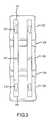
- FIG. 3shows a top plan view of another stabilization device consistent with an embodiment of the present invention
- FIG. 4shows a cross-sectional view of another stabilization device consistent with an embodiment of the present invention
- FIGS. 5A and 5Bshow another stabilization device consistent with an embodiment of the present invention
- FIGS. 6A-6Cshow another stabilization device consistent with an embodiment of the present invention.
- FIGS. 7A , 7 B, and 7 Cshow another stabilization device consistent with an embodiment of the present invention.
- Spinal stabilization segment 100includes a superior vertebral body 102 and an inferior vertebral body 104 separated by an intervertebral disc space 106 .
- Intervertebral disc space 106is generally occupied by an intervertebral disc 108 having an annulus 110 encapsulating a disc nucleus 112 .
- spinal stabilization devices 120Extending between superior vertebral body 102 and inferior vertebral body 104 are two spinal stabilization devices 120 . While two spinal stabilization device 120 are shown, more or less could be used. However, parallel devices is relatively conventional in spinal applications. The spinal stabilization devices are identical so only one will be described herein for convenience. Spinal stabilization device 120 may be a cylindrical rod, a square rod, an elliptical rod, or any geometric shape as a matter of design choice. Moreover, a single plate could be used as a substitute for the two bars shown. Spinal stabilization device 120 may be an type of biocompatible material including, for example, titanium, nitinol, other metal alloys, plastics, synthetics, or the like.
- Spinal stabilization device 120has at least one elongated bore 122 , typically shaped like an oval, but other geometric shapes or random shapes are possible, at a first end 124 of spinal stabilization device 120 .
- Elongated bore 122defines a slot 126 .
- a bore 128exists at a second end 130 of spinal stabilization device 120 .
- Bore 128may be replaced with an elongated bore 122 , which is shown in phantom, such that spinal stabilization device has elongated bores 122 at both first end 124 and second end 130 .
- Pedicle screws 132are threaded through elongated bore 122 and bore 126 into the pedicles of superior vertebral body 102 and inferior vertebral body 104 .
- superior pedicle screwis identified as 132 s and inferior pedicle screw is designated 132 i .
- elongated bore 122is shown aligned with superior vertebral body 102 , it could easily be aligned with inferior vertebral body 104 .
- a nut 134 or coupling devicemay be threaded onto a head 136 of pedicle screws 132 .
- Slot 126is filled with a biocompatible flexible or elastic material 138 , such as, a biocompatible resin or electromeric compound, shown by cross-hatch.
- Elastic material 138allows relative and limited movement in both a flexion and extension directions as represented by arrow 140 .
- the slot 126 filled with elastic material 138provides a means to provide stabilized, dampened movement between vertebral bodies.
- Elastic material 138could be any number of biocompatible plastics, resins, metals, alloys or the like.
- elastic materialcould be an elastomeric polymer such as silicone rubber, polyurethane, SULENE®, available from Sulzer Brothers Limited Corporation, Switzerland.
- Other materialsinclude springs, spring metal, struts, alloys such as Shaped memory alloys, titanium, or the like.
- spinal stabilization device 120is fixedly attached to inferior vertebral body 104 .
- the inferior vertebral body 104 and superior vertebral body 102begin to move apart.
- Spinal stabilization device 120moves in relation to inferior vertebral body 104 .
- movement of inferior vertebral body 104 and spinal stabilization device 120does not influence the movement of superior body 102 , which would move in accordance with a conventional flex motion of the person.
- pedicle screw 132s to move towards first end 124 of spinal stabilization device 120 in slot 126 . Movement of pedicle screw 132 s in slot 126 causes compression of elastic material 138 .
- material 140would decay over time and elastic material 138 would become increasingly more elastic.
- material 140would act as a lock to allow bone growth, for example, to fuse vertebral bodies 102 and 104 with pedicle screws 132 .
- material 140would begin to decay allowing the relative motion described above.
- material 140would comprise a resorbable material, but any material that is biocompatible and decays over time would be useable. While shown as discrete particles, elastic material and material 140 may form a homogeneous resin or the like.
- material 140could form a separate layer of material in bore 122 , which is shown in phantom on FIG. 2 .
- the separate layercould reside in the bore proximate the bone interface, opposite the bone interface, or interspersed throughout the bore.
- multiple layers of materialare possible.
- Packing material 140such as a resorbable material, into elongated bore 122 provides a contained volume into which material 140 can be placed. Packing material 140 into the contained space allows material 140 to provide a high resistance to movement, which allows pedicles screws to fuse and anchor, but does not require material 140 to resist shear forces. This is useful for resorbable materials as they can provide relatively high compression resistance, but generally have limited or relatively low resistance to shear forces.
- Elongated bore 122may be designed with a shoulder 202 recessed from a surface 204 of spinal stabilization device 120 .
- a channel 206would be formed in surface 204 .
- Nut 134would rest on shoulder 202 in channel 206 to provide a lower profile for the device.
- FIG. 1shows two vertebral bodies 102 and 104 separated by one intervertebral disc 108 (also known herein as a single level), one of ordinary skill in the art would recognize the present invention could be use for two, three, or more level device as necessary.
- FIG. 3shows spinal stabilization device 300 extending from a superior vertebral body 302 to an inferior vertebral body 304 across an intermediate vertebral body 306 .
- Superior vertebral body 302is separated from intermediate vertebral body 306 by a superior intervertebral disc space 308 and inferior vertebral body 302 is separated from intermediate vertebral body 306 by inferior intervertebral disc space 310 .
- an elongated bore 312resides at both a first end 314 aligned with superior vertebral body 302 and a second end 316 aligned with inferior vertebral body 304 .
- a conventional bore 318is aligned with intermediate vertebral body 306 .
- FIG. 4shows a micro-motion multi-axial pedicles screw anchor 402 containing a rod 404 . While shown as multi-axial, anchor 402 does not need to be a multi-axial device.
- a set screw 406couples (such as by corresponding threads) into saddle 408 to provide seating force to rod 404 .
- Anchor 402provides a section with elastic material 138 and material 140 about a pedicle screw 410 threaded into pedicle 412 .
- Pedicle screw 410has a connector 414 to allow a tool, such as a hex driver, to thread pedicle screw 410 into pedicle 412 .
- Elastic material 138 and material 140may be any combination of elements as outlined above.
- a spacer 420which may simply be an air gap or some non-compressible material, resides between saddle 408 and screw 410 . Spacer 420 inhibits the compressive force supplied by set screw 406 from locking pedicle screw 410 in place.
- Elastic material 138provides dampened motion in both the flex and extension directions.
- Material 140such as a resorbable or other degradable material, initially restricts the motion until pedicle screw 410 and pedicle 412 fuse. As material 140 degrades, elastic material 138 allows more motion and provides a shock absorbing effect as well.
- Rod based stabilization device 500is shown extending across inferior vertebrae 104 , superior vertebrae 102 and disc space 106 .
- Rod based stabilization devicecomprises screw anchors 502 with pedicle screws 504 threaded into superior pedicle 102 and inferior pedicle 104 .
- a rod 510extends between anchors 502 .
- Anchors 502 and pedicle screws 504can be any conventional device as known in the art and will not be further explained herein.
- Rod 510comprises an inferior rod part 512 and a superior rod part 514 .
- Inferior rod part 512is coupled to superior rod part 514 by a rod interface 516 .
- Rod interfacewill be explained with reference to FIG. 5B . While shown as having identical sizes/diameters, inferior rod part 512 , superior rod part 514 , and rod interface 516 may have different sizes/diameters.
- Rod interface 516is shown in more detail.
- Rod interfacecomprises a female socket portion 518 attached to inferior rod part 512 and a male protrusion portion 520 attached to superior rod part 514 .
- Female socket portion 518could be connected to superior rod part 514 and male protrusion portion 520 could be attached to inferior rod part 512 instead.
- Female socket portion 518forms a space 522 that may end in protrusion 524 .
- Space 522is filled with both elastic material 138 and material 140 .
- Male protrusion portion 520is fitted in space 522 such that elastic material 138 and, at least temporarily, material 140 couples, bonds, or adherers male protrusion 520 to socket 518 .
- Material 140being relatively rigid prevents motion, but once degraded, elastic material 138 allows limited motion between male protrusion portion 520 and female socket portion 518 , which allows some flex and extension of the spine.
- female socket portion 518may be formed with perforations 526 .
- Device 600includes anchors 602 and a rod 604 with a dynamic termination 606 .
- Rod 604extends between anchors 602 across inferior vertebrae 104 , superior vertebrae 102 , and disc space 106 .
- Dynamic termination 606may reside proximate either the inferior pedicle 104 , the superior pedicle 102 , or both.
- dynamic termination 606includes a male protrusion 608 attached to rod 604 .
- Male protrusion 608extends into a recess 612 formed by a termination cap 610 .
- Male protrusion 608may terminate with a protrusion 614 , such as a flange or rib, and termination cap 610 may have a protrusion 616 , such as shoulders, to inhibit male protrusion 608 from dislodging from termination cap 610 .
- Male protrusion 608is coupled, bonded, adhered to termination cap 610 by elastic material 138 and material 140 residing in recess 612 .
- Termination cap 610may have a lid 618 to apply more or less volume associated with recess 612 .
- Termination cap 610may have perforations 620 to facilitate absorption of material 140 .
- Termination cap 610may be formed with multiple stages as shown in FIG. 6C .
- Recess 612may have a first portion 622 with a first width W 1 to hold material 140 .
- Protrusion 614may reside in first portion 622 .
- Material 140 compressing protrusion 614would inhibit motion of rod 604 .
- Recess 612would have a second portion 624 having a second width W 2 to hold elastic material 138 .
- Stabilization device 700comprises a spinal plate 702 , such as an anterior cervical plate as shown, having a first end 704 and a second end 706 opposite first end 704 .
- First end 704is provided with a pair of elongated bores 708 .
- Second end 706is provided with a pair of conventional bores 710 .
- Conventional bores 710may be replaced with elongated bores 708 .
- FIG. 7Bone elongated bore 708 is shown in more detail.
- Struts 714may be any of the above mentioned materials or milled into plate 702 . While shown with 4 struts 714 , more or less struts are possible. The remainder of elongated bore is filled with material 140 to inhibit motion while pedicle screws and pedicles are fusing. Once fused, struts 714 allow limited motion between the vertebrae. Struts 714 are shown with an accordion shape to facilitate elastic movement, but other devices and shapes to allow movement are possible, such as making struts from shaped memory alloys.
- FIG. 7Cshows a cross sectional view across elongated bore 708 .
Landscapes
- Health & Medical Sciences (AREA)
- Orthopedic Medicine & Surgery (AREA)
- Life Sciences & Earth Sciences (AREA)
- Neurology (AREA)
- Surgery (AREA)
- Heart & Thoracic Surgery (AREA)
- Engineering & Computer Science (AREA)
- Biomedical Technology (AREA)
- Nuclear Medicine, Radiotherapy & Molecular Imaging (AREA)
- Medical Informatics (AREA)
- Molecular Biology (AREA)
- Animal Behavior & Ethology (AREA)
- General Health & Medical Sciences (AREA)
- Public Health (AREA)
- Veterinary Medicine (AREA)
- Surgical Instruments (AREA)
- Prostheses (AREA)
Abstract
Description
Claims (7)
Priority Applications (4)
| Application Number | Priority Date | Filing Date | Title |
|---|---|---|---|
| US11/549,675US7828830B2 (en) | 2005-05-12 | 2006-10-16 | Dynamic spinal stabilization |
| ES07844324.9TES2537961T3 (en) | 2006-10-16 | 2007-10-16 | Dynamic spinal stabilization |
| EP07844324.9AEP2083717B1 (en) | 2006-10-16 | 2007-10-16 | Dynamic spinal stabilization |
| PCT/US2007/081542WO2008048973A2 (en) | 2006-10-16 | 2007-10-16 | Dynamic spinal stabilization |
Applications Claiming Priority (3)
| Application Number | Priority Date | Filing Date | Title |
|---|---|---|---|
| US11/128,960US20060271055A1 (en) | 2005-05-12 | 2005-05-12 | Spinal stabilization |
| US11/128,962US20060271048A1 (en) | 2005-05-12 | 2005-05-12 | Pedicle screw based vertebral body stabilization apparatus |
| US11/549,675US7828830B2 (en) | 2005-05-12 | 2006-10-16 | Dynamic spinal stabilization |
Related Parent Applications (2)
| Application Number | Title | Priority Date | Filing Date |
|---|---|---|---|
| US11/128,960Continuation-In-PartUS20060271055A1 (en) | 2005-05-12 | 2005-05-12 | Spinal stabilization |
| US11/128,962Continuation-In-PartUS20060271048A1 (en) | 2005-05-12 | 2005-05-12 | Pedicle screw based vertebral body stabilization apparatus |
Publications (2)
| Publication Number | Publication Date |
|---|---|
| US20070161997A1 US20070161997A1 (en) | 2007-07-12 |
| US7828830B2true US7828830B2 (en) | 2010-11-09 |
Family
ID=39314798
Family Applications (1)
| Application Number | Title | Priority Date | Filing Date |
|---|---|---|---|
| US11/549,675Expired - Fee RelatedUS7828830B2 (en) | 2005-05-12 | 2006-10-16 | Dynamic spinal stabilization |
Country Status (4)
| Country | Link |
|---|---|
| US (1) | US7828830B2 (en) |
| EP (1) | EP2083717B1 (en) |
| ES (1) | ES2537961T3 (en) |
| WO (1) | WO2008048973A2 (en) |
Cited By (24)
| Publication number | Priority date | Publication date | Assignee | Title |
|---|---|---|---|---|
| US20100057126A1 (en)* | 2008-09-04 | 2010-03-04 | Zimmer Spine, Inc. | Dynamic vertebral fastener |
| US8007518B2 (en) | 2008-02-26 | 2011-08-30 | Spartek Medical, Inc. | Load-sharing component having a deflectable post and method for dynamic stabilization of the spine |
| US8012181B2 (en) | 2008-02-26 | 2011-09-06 | Spartek Medical, Inc. | Modular in-line deflection rod and bone anchor system and method for dynamic stabilization of the spine |
| US8016861B2 (en) | 2008-02-26 | 2011-09-13 | Spartek Medical, Inc. | Versatile polyaxial connector assembly and method for dynamic stabilization of the spine |
| US8021396B2 (en) | 2007-06-05 | 2011-09-20 | Spartek Medical, Inc. | Configurable dynamic spinal rod and method for dynamic stabilization of the spine |
| US8048115B2 (en) | 2007-06-05 | 2011-11-01 | Spartek Medical, Inc. | Surgical tool and method for implantation of a dynamic bone anchor |
| US8057517B2 (en) | 2008-02-26 | 2011-11-15 | Spartek Medical, Inc. | Load-sharing component having a deflectable post and centering spring and method for dynamic stabilization of the spine |
| US8083772B2 (en) | 2007-06-05 | 2011-12-27 | Spartek Medical, Inc. | Dynamic spinal rod assembly and method for dynamic stabilization of the spine |
| US8083775B2 (en) | 2008-02-26 | 2011-12-27 | Spartek Medical, Inc. | Load-sharing bone anchor having a natural center of rotation and method for dynamic stabilization of the spine |
| US8092501B2 (en) | 2007-06-05 | 2012-01-10 | Spartek Medical, Inc. | Dynamic spinal rod and method for dynamic stabilization of the spine |
| US8097024B2 (en) | 2008-02-26 | 2012-01-17 | Spartek Medical, Inc. | Load-sharing bone anchor having a deflectable post and method for stabilization of the spine |
| US8114134B2 (en) | 2007-06-05 | 2012-02-14 | Spartek Medical, Inc. | Spinal prosthesis having a three bar linkage for motion preservation and dynamic stabilization of the spine |
| US8211155B2 (en) | 2008-02-26 | 2012-07-03 | Spartek Medical, Inc. | Load-sharing bone anchor having a durable compliant member and method for dynamic stabilization of the spine |
| US8257397B2 (en) | 2009-12-02 | 2012-09-04 | Spartek Medical, Inc. | Low profile spinal prosthesis incorporating a bone anchor having a deflectable post and a compound spinal rod |
| US8267979B2 (en) | 2008-02-26 | 2012-09-18 | Spartek Medical, Inc. | Load-sharing bone anchor having a deflectable post and axial spring and method for dynamic stabilization of the spine |
| US8317836B2 (en) | 2007-06-05 | 2012-11-27 | Spartek Medical, Inc. | Bone anchor for receiving a rod for stabilization and motion preservation spinal implantation system and method |
| US8333792B2 (en) | 2008-02-26 | 2012-12-18 | Spartek Medical, Inc. | Load-sharing bone anchor having a deflectable post and method for dynamic stabilization of the spine |
| US8337536B2 (en) | 2008-02-26 | 2012-12-25 | Spartek Medical, Inc. | Load-sharing bone anchor having a deflectable post with a compliant ring and method for stabilization of the spine |
| US8430916B1 (en) | 2012-02-07 | 2013-04-30 | Spartek Medical, Inc. | Spinal rod connectors, methods of use, and spinal prosthesis incorporating spinal rod connectors |
| US8518085B2 (en) | 2010-06-10 | 2013-08-27 | Spartek Medical, Inc. | Adaptive spinal rod and methods for stabilization of the spine |
| US20140142630A1 (en)* | 2011-07-25 | 2014-05-22 | Nedicrea International | Anchor member for vertebral osteosynthesis equipment |
| US11051857B2 (en) | 2017-08-10 | 2021-07-06 | Ortho Development Corporation | Tether clamping assemblies and related methods and apparatus |
| US11071569B2 (en) | 2017-08-10 | 2021-07-27 | Ortho Development Corporation | Nesting tether clamping assemblies and related methods and apparatus |
| US11819255B2 (en) | 2019-10-07 | 2023-11-21 | Ortho Development Corporation | Tether tensioning instrumentation and related methods |
Families Citing this family (79)
| Publication number | Priority date | Publication date | Assignee | Title |
|---|---|---|---|---|
| US7833250B2 (en) | 2004-11-10 | 2010-11-16 | Jackson Roger P | Polyaxial bone screw with helically wound capture connection |
| US7862587B2 (en) | 2004-02-27 | 2011-01-04 | Jackson Roger P | Dynamic stabilization assemblies, tool set and method |
| US10729469B2 (en) | 2006-01-09 | 2020-08-04 | Roger P. Jackson | Flexible spinal stabilization assembly with spacer having off-axis core member |
| US10258382B2 (en) | 2007-01-18 | 2019-04-16 | Roger P. Jackson | Rod-cord dynamic connection assemblies with slidable bone anchor attachment members along the cord |
| US8292926B2 (en) | 2005-09-30 | 2012-10-23 | Jackson Roger P | Dynamic stabilization connecting member with elastic core and outer sleeve |
| US8353932B2 (en) | 2005-09-30 | 2013-01-15 | Jackson Roger P | Polyaxial bone anchor assembly with one-piece closure, pressure insert and plastic elongate member |
| WO2006052796A2 (en) | 2004-11-10 | 2006-05-18 | Jackson Roger P | Helical guide and advancement flange with break-off extensions |
| US8876868B2 (en) | 2002-09-06 | 2014-11-04 | Roger P. Jackson | Helical guide and advancement flange with radially loaded lip |
| US7621918B2 (en) | 2004-11-23 | 2009-11-24 | Jackson Roger P | Spinal fixation tool set and method |
| US7377923B2 (en) | 2003-05-22 | 2008-05-27 | Alphatec Spine, Inc. | Variable angle spinal screw assembly |
| US7766915B2 (en) | 2004-02-27 | 2010-08-03 | Jackson Roger P | Dynamic fixation assemblies with inner core and outer coil-like member |
| US8366753B2 (en) | 2003-06-18 | 2013-02-05 | Jackson Roger P | Polyaxial bone screw assembly with fixed retaining structure |
| US7967850B2 (en) | 2003-06-18 | 2011-06-28 | Jackson Roger P | Polyaxial bone anchor with helical capture connection, insert and dual locking assembly |
| US8926670B2 (en) | 2003-06-18 | 2015-01-06 | Roger P. Jackson | Polyaxial bone screw assembly |
| US7776067B2 (en) | 2005-05-27 | 2010-08-17 | Jackson Roger P | Polyaxial bone screw with shank articulation pressure insert and method |
| US8092500B2 (en) | 2007-05-01 | 2012-01-10 | Jackson Roger P | Dynamic stabilization connecting member with floating core, compression spacer and over-mold |
| US11419642B2 (en) | 2003-12-16 | 2022-08-23 | Medos International Sarl | Percutaneous access devices and bone anchor assemblies |
| US7179261B2 (en) | 2003-12-16 | 2007-02-20 | Depuy Spine, Inc. | Percutaneous access devices and bone anchor assemblies |
| US7527638B2 (en) | 2003-12-16 | 2009-05-05 | Depuy Spine, Inc. | Methods and devices for minimally invasive spinal fixation element placement |
| JP2007525274A (en) | 2004-02-27 | 2007-09-06 | ロジャー・ピー・ジャクソン | Orthopedic implant rod reduction instrument set and method |
| US11241261B2 (en) | 2005-09-30 | 2022-02-08 | Roger P Jackson | Apparatus and method for soft spinal stabilization using a tensionable cord and releasable end structure |
| US7160300B2 (en) | 2004-02-27 | 2007-01-09 | Jackson Roger P | Orthopedic implant rod reduction tool set and method |
| US8152810B2 (en) | 2004-11-23 | 2012-04-10 | Jackson Roger P | Spinal fixation tool set and method |
| DE202004020396U1 (en) | 2004-08-12 | 2005-07-07 | Columbus Trading-Partners Pos und Brendel GbR (vertretungsberechtigte Gesellschafter Karin Brendel, 95503 Hummeltal und Bohumila Pos, 95445 Bayreuth) | Child seat for motor vehicles |
| US7651502B2 (en) | 2004-09-24 | 2010-01-26 | Jackson Roger P | Spinal fixation tool set and method for rod reduction and fastener insertion |
| US20100036423A1 (en)* | 2004-10-20 | 2010-02-11 | Stanley Kyle Hayes | Dynamic rod |
| US7935134B2 (en) | 2004-10-20 | 2011-05-03 | Exactech, Inc. | Systems and methods for stabilization of bone structures |
| US8025680B2 (en) | 2004-10-20 | 2011-09-27 | Exactech, Inc. | Systems and methods for posterior dynamic stabilization of the spine |
| US8162985B2 (en) | 2004-10-20 | 2012-04-24 | The Board Of Trustees Of The Leland Stanford Junior University | Systems and methods for posterior dynamic stabilization of the spine |
| US8926672B2 (en) | 2004-11-10 | 2015-01-06 | Roger P. Jackson | Splay control closure for open bone anchor |
| US9216041B2 (en) | 2009-06-15 | 2015-12-22 | Roger P. Jackson | Spinal connecting members with tensioned cords and rigid sleeves for engaging compression inserts |
| US9168069B2 (en) | 2009-06-15 | 2015-10-27 | Roger P. Jackson | Polyaxial bone anchor with pop-on shank and winged insert with lower skirt for engaging a friction fit retainer |
| WO2006057837A1 (en) | 2004-11-23 | 2006-06-01 | Jackson Roger P | Spinal fixation tool attachment structure |
| US8444681B2 (en) | 2009-06-15 | 2013-05-21 | Roger P. Jackson | Polyaxial bone anchor with pop-on shank, friction fit retainer and winged insert |
| US9980753B2 (en) | 2009-06-15 | 2018-05-29 | Roger P Jackson | pivotal anchor with snap-in-place insert having rotation blocking extensions |
| US7901437B2 (en) | 2007-01-26 | 2011-03-08 | Jackson Roger P | Dynamic stabilization member with molded connection |
| US10076361B2 (en) | 2005-02-22 | 2018-09-18 | Roger P. Jackson | Polyaxial bone screw with spherical capture, compression and alignment and retention structures |
| US8105368B2 (en) | 2005-09-30 | 2012-01-31 | Jackson Roger P | Dynamic stabilization connecting member with slitted core and outer sleeve |
| US20080058808A1 (en) | 2006-06-14 | 2008-03-06 | Spartek Medical, Inc. | Implant system and method to treat degenerative disorders of the spine |
| CA2670988C (en) | 2006-12-08 | 2014-03-25 | Roger P. Jackson | Tool system for dynamic spinal implants |
| US8475498B2 (en) | 2007-01-18 | 2013-07-02 | Roger P. Jackson | Dynamic stabilization connecting member with cord connection |
| US8366745B2 (en) | 2007-05-01 | 2013-02-05 | Jackson Roger P | Dynamic stabilization assembly having pre-compressed spacers with differential displacements |
| US8012177B2 (en) | 2007-02-12 | 2011-09-06 | Jackson Roger P | Dynamic stabilization assembly with frusto-conical connection |
| US10383660B2 (en) | 2007-05-01 | 2019-08-20 | Roger P. Jackson | Soft stabilization assemblies with pretensioned cords |
| US8979904B2 (en) | 2007-05-01 | 2015-03-17 | Roger P Jackson | Connecting member with tensioned cord, low profile rigid sleeve and spacer with torsion control |
| CA2690038C (en) | 2007-05-31 | 2012-11-27 | Roger P. Jackson | Dynamic stabilization connecting member with pre-tensioned solid core |
| US8052722B2 (en) | 2007-06-05 | 2011-11-08 | Spartek Medical, Inc. | Dual deflection rod system for a dynamic stabilization and motion preservation spinal implantation system and method |
| US8109970B2 (en) | 2007-06-05 | 2012-02-07 | Spartek Medical, Inc. | Deflection rod system with a deflection contouring shield for a spine implant and method |
| US8911477B2 (en) | 2007-10-23 | 2014-12-16 | Roger P. Jackson | Dynamic stabilization member with end plate support and cable core extension |
| US8131339B2 (en)* | 2007-11-27 | 2012-03-06 | Vivant Medical, Inc. | System and method for field ablation prediction |
| US20090240284A1 (en)* | 2008-03-24 | 2009-09-24 | David Scott Randol | Stabilization rods |
| AU2010260521C1 (en) | 2008-08-01 | 2013-08-01 | Roger P. Jackson | Longitudinal connecting member with sleeved tensioned cords |
| US8372116B2 (en) | 2009-04-13 | 2013-02-12 | Warsaw Orthopedic, Inc. | Systems and devices for dynamic stabilization of the spine |
| US8425562B2 (en)* | 2009-04-13 | 2013-04-23 | Warsaw Orthopedic, Inc. | Systems and devices for dynamic stabilization of the spine |
| US8206419B2 (en) | 2009-04-13 | 2012-06-26 | Warsaw Orthopedic, Inc. | Systems and devices for dynamic stabilization of the spine |
| US8998959B2 (en) | 2009-06-15 | 2015-04-07 | Roger P Jackson | Polyaxial bone anchors with pop-on shank, fully constrained friction fit retainer and lock and release insert |
| US11229457B2 (en) | 2009-06-15 | 2022-01-25 | Roger P. Jackson | Pivotal bone anchor assembly with insert tool deployment |
| CN103826560A (en) | 2009-06-15 | 2014-05-28 | 罗杰.P.杰克逊 | Polyaxial Bone Anchor with Socket Stem and Winged Inserts with Friction Fit Compression Collars |
| US9668771B2 (en) | 2009-06-15 | 2017-06-06 | Roger P Jackson | Soft stabilization assemblies with off-set connector |
| US8834553B2 (en) | 2009-09-11 | 2014-09-16 | Gi Dynamics, Inc. | Anchors with biodegradable constraints |
| AU2010292118B9 (en) | 2009-09-11 | 2014-01-09 | Gi Dynamics, Inc. | Anchors with open heads |
| EP2485654B1 (en) | 2009-10-05 | 2021-05-05 | Jackson P. Roger | Polyaxial bone anchor with non-pivotable retainer and pop-on shank, some with friction fit |
| WO2011063020A1 (en)* | 2009-11-18 | 2011-05-26 | Seaspine, Inc. | Flexible screw head constructs for spinal stabilization |
| EP2519193A1 (en)* | 2009-12-30 | 2012-11-07 | Synthes GmbH | Intergrated multi-material implants and methods of manufacture |
| AU2011299558A1 (en) | 2010-09-08 | 2013-05-02 | Roger P. Jackson | Dynamic stabilization members with elastic and inelastic sections |
| AU2011324058A1 (en) | 2010-11-02 | 2013-06-20 | Roger P. Jackson | Polyaxial bone anchor with pop-on shank and pivotable retainer |
| JP5865479B2 (en) | 2011-03-24 | 2016-02-17 | ロジャー・ピー・ジャクソン | Multiaxial bone anchor with compound joint and pop-mounted shank |
| CN103536345B (en)* | 2012-07-17 | 2016-03-23 | 上海微创骨科医疗科技有限公司 | A kind of spinal column dynamic stability implants unit |
| US8911478B2 (en) | 2012-11-21 | 2014-12-16 | Roger P. Jackson | Splay control closure for open bone anchor |
| US10058354B2 (en) | 2013-01-28 | 2018-08-28 | Roger P. Jackson | Pivotal bone anchor assembly with frictional shank head seating surfaces |
| US8852239B2 (en) | 2013-02-15 | 2014-10-07 | Roger P Jackson | Sagittal angle screw with integral shank and receiver |
| US9566092B2 (en) | 2013-10-29 | 2017-02-14 | Roger P. Jackson | Cervical bone anchor with collet retainer and outer locking sleeve |
| US9717533B2 (en) | 2013-12-12 | 2017-08-01 | Roger P. Jackson | Bone anchor closure pivot-splay control flange form guide and advancement structure |
| US9451993B2 (en) | 2014-01-09 | 2016-09-27 | Roger P. Jackson | Bi-radial pop-on cervical bone anchor |
| US9597119B2 (en) | 2014-06-04 | 2017-03-21 | Roger P. Jackson | Polyaxial bone anchor with polymer sleeve |
| US10064658B2 (en) | 2014-06-04 | 2018-09-04 | Roger P. Jackson | Polyaxial bone anchor with insert guides |
| EP3085319B1 (en)* | 2015-04-21 | 2017-10-11 | Biedermann Technologies GmbH & Co. KG | Template for use in manufacturing an implant for spinal or other orthopaedic fixation and method of manufacturing such a template |
| CN111419366A (en)* | 2020-04-03 | 2020-07-17 | 董谢平 | Pedicle screw-rod system capable of changing rigidity into flexibility into rigidity |
| US12290296B2 (en) | 2020-07-02 | 2025-05-06 | Xieping DONG | Bone fixation system capable of gradually changing from rigid fixation to axial non-rigid fixation |
Citations (62)
| Publication number | Priority date | Publication date | Assignee | Title |
|---|---|---|---|---|
| US4338926A (en) | 1980-11-21 | 1982-07-13 | Howmedica, Inc. | Bone fracture prosthesis with controlled stiffness |
| US4599085A (en) | 1979-07-11 | 1986-07-08 | Neodontics, Inc. | Bone implant member for prostheses and bone connecting elements and process for the production thereof |
| US4653481A (en) | 1985-07-24 | 1987-03-31 | Howland Robert S | Advanced spine fixation system and method |
| EP0322334A1 (en) | 1987-12-23 | 1989-06-28 | Cremascoli France | Prosthesis implanted between vertebral spinous processes |
| US5005562A (en) | 1988-06-24 | 1991-04-09 | Societe De Fabrication De Material Orthopedique | Implant for spinal osteosynthesis device, in particular in traumatology |
| US5074864A (en) | 1988-12-21 | 1991-12-24 | Zimmer, Inc. | Clamp assembly for use in a spinal system |
| US5147359A (en) | 1988-12-21 | 1992-09-15 | Zimmer, Inc. | Spinal hook body |
| US5154718A (en) | 1988-12-21 | 1992-10-13 | Zimmer, Inc. | Spinal coupler assembly |
| US5180393A (en) | 1990-09-21 | 1993-01-19 | Polyclinique De Bourgogne & Les Hortensiad | Artificial ligament for the spine |
| US5201734A (en) | 1988-12-21 | 1993-04-13 | Zimmer, Inc. | Spinal locking sleeve assembly |
| US5306275A (en) | 1992-12-31 | 1994-04-26 | Bryan Donald W | Lumbar spine fixation apparatus and method |
| US5470333A (en) | 1993-03-11 | 1995-11-28 | Danek Medical, Inc. | System for stabilizing the cervical and the lumbar region of the spine |
| US5496318A (en) | 1993-01-08 | 1996-03-05 | Advanced Spine Fixation Systems, Inc. | Interspinous segmental spine fixation device |
| US5531745A (en) | 1993-03-11 | 1996-07-02 | Danek Medical, Inc. | System for stabilizing the spine and reducing spondylolisthesis |
| US5609634A (en) | 1992-07-07 | 1997-03-11 | Voydeville; Gilles | Intervertebral prosthesis making possible rotatory stabilization and flexion/extension stabilization |
| US5645599A (en) | 1994-07-26 | 1997-07-08 | Fixano | Interspinal vertebral implant |
| US5658335A (en) | 1995-03-09 | 1997-08-19 | Cohort Medical Products Group, Inc. | Spinal fixator |
| US5683390A (en) | 1994-02-22 | 1997-11-04 | Howmedica Gmbh | Correcting a spinal column |
| US5683404A (en) | 1996-06-05 | 1997-11-04 | Metagen, Llc | Clamp and method for its use |
| US5725582A (en) | 1992-08-19 | 1998-03-10 | Surgicraft Limited | Surgical implants |
| US5800550A (en) | 1996-03-13 | 1998-09-01 | Sertich; Mario M. | Interbody fusion cage |
| US5836948A (en) | 1997-01-02 | 1998-11-17 | Saint Francis Medical Technologies, Llc | Spine distraction implant and method |
| US6113602A (en) | 1999-03-26 | 2000-09-05 | Sulzer Spine-Tech Inc. | Posterior spinal instrument guide and method |
| US6135772A (en) | 1994-08-15 | 2000-10-24 | Jones; Shedrick D. | Method and apparatus for implantation |
| US6156040A (en) | 1997-08-29 | 2000-12-05 | Sulzer Spine-Tech Inc. | Apparatus and method for spinal stablization |
| US20010012938A1 (en) | 1997-01-02 | 2001-08-09 | Zucherman James F. | Spine distraction implant |
| US6277094B1 (en) | 1999-04-28 | 2001-08-21 | Medtronic, Inc. | Apparatus and method for dilating ligaments and tissue by the alternating insertion of expandable tubes |
| US6293949B1 (en) | 2000-03-01 | 2001-09-25 | Sdgi Holdings, Inc. | Superelastic spinal stabilization system and method |
| US20020029039A1 (en) | 1997-01-02 | 2002-03-07 | Zucherman James F. | Supplemental spine fixation device and methods |
| US6440169B1 (en) | 1998-02-10 | 2002-08-27 | Dimso | Interspinous stabilizer to be fixed to spinous processes of two vertebrae |
| US6451019B1 (en) | 1998-10-20 | 2002-09-17 | St. Francis Medical Technologies, Inc. | Supplemental spine fixation device and method |
| US20020147449A1 (en) | 2001-04-09 | 2002-10-10 | David Yun | Spine fixation device and method |
| US20020156150A1 (en) | 1999-03-25 | 2002-10-24 | Metabolix, Inc. | Medical devices and applications of polyhydroxyalkanoate polymers |
| US6599294B2 (en) | 1999-01-30 | 2003-07-29 | Aesculap Ag & Co. Kg | Surgical instrument for introducing intervertebral implants |
| US20030153915A1 (en) | 2002-02-08 | 2003-08-14 | Showa Ika Kohgyo Co., Ltd. | Vertebral body distance retainer |
| US20030180266A1 (en) | 1997-07-30 | 2003-09-25 | Mckay William F. | Methods of expressing LIM mineralization protein in non-osseous cells |
| US6626944B1 (en) | 1998-02-20 | 2003-09-30 | Jean Taylor | Interspinous prosthesis |
| US20030187509A1 (en) | 2002-04-01 | 2003-10-02 | Lemole G. Michael | Modulus plating system and method |
| US6635060B2 (en) | 2000-07-06 | 2003-10-21 | Sulzer Spine-Tech Inc. | Bone preparation instruments and methods |
| US20030216736A1 (en) | 2002-05-17 | 2003-11-20 | Robinson James C. | Device for fixation of spinous processes |
| US6652527B2 (en) | 1998-10-20 | 2003-11-25 | St. Francis Medical Technologies, Inc. | Supplemental spine fixation device and method |
| US20030225021A1 (en) | 2001-11-14 | 2003-12-04 | Mckay William F. | Methods of inducing the expression of bone morphogenetic proteins (BMPs) and transforming growth factor-beta proteins (TGF-betas) in cells |
| US20040024458A1 (en) | 2000-12-22 | 2004-02-05 | Jacques Senegas | Intervertebral implant with deformable wedge |
| US20040059337A1 (en) | 2000-07-06 | 2004-03-25 | Sulzer Spine-Tech Inc. | Bone preparation instruments and methods |
| US20040059339A1 (en) | 2002-09-19 | 2004-03-25 | Roehm Thomas E. | Oval dilator and retractor set and method |
| US6719795B1 (en) | 2001-04-25 | 2004-04-13 | Macropore Biosurgery, Inc. | Resorbable posterior spinal fusion system |
| US20040106995A1 (en) | 2000-07-12 | 2004-06-03 | Regis Le Couedic | Shock-absorbing intervertebral implant |
| US6761720B1 (en) | 1999-10-15 | 2004-07-13 | Spine Next | Intervertebral implant |
| US20040167520A1 (en) | 1997-01-02 | 2004-08-26 | St. Francis Medical Technologies, Inc. | Spinous process implant with tethers |
| US6783527B2 (en) | 2001-10-30 | 2004-08-31 | Sdgi Holdings, Inc. | Flexible spinal stabilization system and method |
| WO2004073533A1 (en) | 2003-02-19 | 2004-09-02 | Sdgi Holdings Inc. | Interspinous device for impeding the movements of two successive vertebrae, and method for making a pad designed for it |
| US6800084B2 (en) | 1998-08-20 | 2004-10-05 | Endius Incorporated | Method for performing a surgical procedure and a cannula for use in performing the surgical procedure |
| US20040199168A1 (en) | 2003-04-02 | 2004-10-07 | Rudolf Bertagnoli | Methods and instrumentation for positioning implants in spinal disc space in an anterior lateral approach |
| US20040225289A1 (en)* | 2003-05-07 | 2004-11-11 | Biedermann Motech Gmbh | Dynamic anchoring device and dynamic stabilization device for bones, in particular for vertebrae, with such an anchoring device |
| US6824565B2 (en) | 2000-09-08 | 2004-11-30 | Nabil L. Muhanna | System and methods for inserting a vertebral spacer |
| US20050085812A1 (en)* | 2003-10-21 | 2005-04-21 | Sherman Michael C. | Apparatus and method for providing dynamizable translations to orthopedic implants |
| WO2005037110A2 (en) | 2003-10-21 | 2005-04-28 | Sdgi Holdings, Inc. | Dynamizable orthopedic implants and their use in treating bone defects |
| US20050136764A1 (en) | 2003-12-18 | 2005-06-23 | Sherman Michael C. | Designed composite degradation for spinal implants |
| US20050143737A1 (en) | 2003-12-31 | 2005-06-30 | John Pafford | Dynamic spinal stabilization system |
| US20060058791A1 (en)* | 2004-08-18 | 2006-03-16 | Richard Broman | Implantable spinal device revision system |
| US7029475B2 (en) | 2003-05-02 | 2006-04-18 | Yale University | Spinal stabilization method |
| US20060271055A1 (en) | 2005-05-12 | 2006-11-30 | Jeffery Thramann | Spinal stabilization |
Family Cites Families (1)
| Publication number | Priority date | Publication date | Assignee | Title |
|---|---|---|---|---|
| US5154716A (en)* | 1990-11-06 | 1992-10-13 | Miles Inc. | Bottom blood bag separation system |
- 2006
- 2006-10-16USUS11/549,675patent/US7828830B2/ennot_activeExpired - Fee Related
- 2007
- 2007-10-16WOPCT/US2007/081542patent/WO2008048973A2/enactiveApplication Filing
- 2007-10-16ESES07844324.9Tpatent/ES2537961T3/enactiveActive
- 2007-10-16EPEP07844324.9Apatent/EP2083717B1/ennot_activeNot-in-force
Patent Citations (67)
| Publication number | Priority date | Publication date | Assignee | Title |
|---|---|---|---|---|
| US4599085A (en) | 1979-07-11 | 1986-07-08 | Neodontics, Inc. | Bone implant member for prostheses and bone connecting elements and process for the production thereof |
| US4338926A (en) | 1980-11-21 | 1982-07-13 | Howmedica, Inc. | Bone fracture prosthesis with controlled stiffness |
| US4653481A (en) | 1985-07-24 | 1987-03-31 | Howland Robert S | Advanced spine fixation system and method |
| EP0322334A1 (en) | 1987-12-23 | 1989-06-28 | Cremascoli France | Prosthesis implanted between vertebral spinous processes |
| US5005562A (en) | 1988-06-24 | 1991-04-09 | Societe De Fabrication De Material Orthopedique | Implant for spinal osteosynthesis device, in particular in traumatology |
| US5201734A (en) | 1988-12-21 | 1993-04-13 | Zimmer, Inc. | Spinal locking sleeve assembly |
| US5074864A (en) | 1988-12-21 | 1991-12-24 | Zimmer, Inc. | Clamp assembly for use in a spinal system |
| US5147359A (en) | 1988-12-21 | 1992-09-15 | Zimmer, Inc. | Spinal hook body |
| US5154718A (en) | 1988-12-21 | 1992-10-13 | Zimmer, Inc. | Spinal coupler assembly |
| US5180393A (en) | 1990-09-21 | 1993-01-19 | Polyclinique De Bourgogne & Les Hortensiad | Artificial ligament for the spine |
| US5609634A (en) | 1992-07-07 | 1997-03-11 | Voydeville; Gilles | Intervertebral prosthesis making possible rotatory stabilization and flexion/extension stabilization |
| US5725582A (en) | 1992-08-19 | 1998-03-10 | Surgicraft Limited | Surgical implants |
| US5306275A (en) | 1992-12-31 | 1994-04-26 | Bryan Donald W | Lumbar spine fixation apparatus and method |
| US5496318A (en) | 1993-01-08 | 1996-03-05 | Advanced Spine Fixation Systems, Inc. | Interspinous segmental spine fixation device |
| US5470333A (en) | 1993-03-11 | 1995-11-28 | Danek Medical, Inc. | System for stabilizing the cervical and the lumbar region of the spine |
| US5531745A (en) | 1993-03-11 | 1996-07-02 | Danek Medical, Inc. | System for stabilizing the spine and reducing spondylolisthesis |
| US5683390A (en) | 1994-02-22 | 1997-11-04 | Howmedica Gmbh | Correcting a spinal column |
| US5645599A (en) | 1994-07-26 | 1997-07-08 | Fixano | Interspinal vertebral implant |
| US6135772A (en) | 1994-08-15 | 2000-10-24 | Jones; Shedrick D. | Method and apparatus for implantation |
| US5658335A (en) | 1995-03-09 | 1997-08-19 | Cohort Medical Products Group, Inc. | Spinal fixator |
| US5800550A (en) | 1996-03-13 | 1998-09-01 | Sertich; Mario M. | Interbody fusion cage |
| US5683404A (en) | 1996-06-05 | 1997-11-04 | Metagen, Llc | Clamp and method for its use |
| US20040167520A1 (en) | 1997-01-02 | 2004-08-26 | St. Francis Medical Technologies, Inc. | Spinous process implant with tethers |
| US20010012938A1 (en) | 1997-01-02 | 2001-08-09 | Zucherman James F. | Spine distraction implant |
| US5836948A (en) | 1997-01-02 | 1998-11-17 | Saint Francis Medical Technologies, Llc | Spine distraction implant and method |
| US20020029039A1 (en) | 1997-01-02 | 2002-03-07 | Zucherman James F. | Supplemental spine fixation device and methods |
| US20030180266A1 (en) | 1997-07-30 | 2003-09-25 | Mckay William F. | Methods of expressing LIM mineralization protein in non-osseous cells |
| US6156040A (en) | 1997-08-29 | 2000-12-05 | Sulzer Spine-Tech Inc. | Apparatus and method for spinal stablization |
| US6440169B1 (en) | 1998-02-10 | 2002-08-27 | Dimso | Interspinous stabilizer to be fixed to spinous processes of two vertebrae |
| US6626944B1 (en) | 1998-02-20 | 2003-09-30 | Jean Taylor | Interspinous prosthesis |
| US6800084B2 (en) | 1998-08-20 | 2004-10-05 | Endius Incorporated | Method for performing a surgical procedure and a cannula for use in performing the surgical procedure |
| US6652527B2 (en) | 1998-10-20 | 2003-11-25 | St. Francis Medical Technologies, Inc. | Supplemental spine fixation device and method |
| US6451019B1 (en) | 1998-10-20 | 2002-09-17 | St. Francis Medical Technologies, Inc. | Supplemental spine fixation device and method |
| US6599294B2 (en) | 1999-01-30 | 2003-07-29 | Aesculap Ag & Co. Kg | Surgical instrument for introducing intervertebral implants |
| US6548569B1 (en) | 1999-03-25 | 2003-04-15 | Metabolix, Inc. | Medical devices and applications of polyhydroxyalkanoate polymers |
| US6838493B2 (en) | 1999-03-25 | 2005-01-04 | Metabolix, Inc. | Medical devices and applications of polyhydroxyalkanoate polymers |
| US20020156150A1 (en) | 1999-03-25 | 2002-10-24 | Metabolix, Inc. | Medical devices and applications of polyhydroxyalkanoate polymers |
| US6113602A (en) | 1999-03-26 | 2000-09-05 | Sulzer Spine-Tech Inc. | Posterior spinal instrument guide and method |
| US6277094B1 (en) | 1999-04-28 | 2001-08-21 | Medtronic, Inc. | Apparatus and method for dilating ligaments and tissue by the alternating insertion of expandable tubes |
| US6761720B1 (en) | 1999-10-15 | 2004-07-13 | Spine Next | Intervertebral implant |
| US6293949B1 (en) | 2000-03-01 | 2001-09-25 | Sdgi Holdings, Inc. | Superelastic spinal stabilization system and method |
| US20040059337A1 (en) | 2000-07-06 | 2004-03-25 | Sulzer Spine-Tech Inc. | Bone preparation instruments and methods |
| US6641582B1 (en) | 2000-07-06 | 2003-11-04 | Sulzer Spine-Tech Inc. | Bone preparation instruments and methods |
| US6635060B2 (en) | 2000-07-06 | 2003-10-21 | Sulzer Spine-Tech Inc. | Bone preparation instruments and methods |
| US20040106995A1 (en) | 2000-07-12 | 2004-06-03 | Regis Le Couedic | Shock-absorbing intervertebral implant |
| US6824565B2 (en) | 2000-09-08 | 2004-11-30 | Nabil L. Muhanna | System and methods for inserting a vertebral spacer |
| US20040024458A1 (en) | 2000-12-22 | 2004-02-05 | Jacques Senegas | Intervertebral implant with deformable wedge |
| US6582433B2 (en) | 2001-04-09 | 2003-06-24 | St. Francis Medical Technologies, Inc. | Spine fixation device and method |
| US20020147449A1 (en) | 2001-04-09 | 2002-10-10 | David Yun | Spine fixation device and method |
| US6719795B1 (en) | 2001-04-25 | 2004-04-13 | Macropore Biosurgery, Inc. | Resorbable posterior spinal fusion system |
| US6783527B2 (en) | 2001-10-30 | 2004-08-31 | Sdgi Holdings, Inc. | Flexible spinal stabilization system and method |
| US7018379B2 (en) | 2001-10-30 | 2006-03-28 | Sdgi Holdings, Inc. | Flexible spinal stabilization system and method |
| US20030225021A1 (en) | 2001-11-14 | 2003-12-04 | Mckay William F. | Methods of inducing the expression of bone morphogenetic proteins (BMPs) and transforming growth factor-beta proteins (TGF-betas) in cells |
| US20030153915A1 (en) | 2002-02-08 | 2003-08-14 | Showa Ika Kohgyo Co., Ltd. | Vertebral body distance retainer |
| US20030187509A1 (en) | 2002-04-01 | 2003-10-02 | Lemole G. Michael | Modulus plating system and method |
| US20030216736A1 (en) | 2002-05-17 | 2003-11-20 | Robinson James C. | Device for fixation of spinous processes |
| US20040059339A1 (en) | 2002-09-19 | 2004-03-25 | Roehm Thomas E. | Oval dilator and retractor set and method |
| WO2004073533A1 (en) | 2003-02-19 | 2004-09-02 | Sdgi Holdings Inc. | Interspinous device for impeding the movements of two successive vertebrae, and method for making a pad designed for it |
| US20040199168A1 (en) | 2003-04-02 | 2004-10-07 | Rudolf Bertagnoli | Methods and instrumentation for positioning implants in spinal disc space in an anterior lateral approach |
| US7029475B2 (en) | 2003-05-02 | 2006-04-18 | Yale University | Spinal stabilization method |
| US20040225289A1 (en)* | 2003-05-07 | 2004-11-11 | Biedermann Motech Gmbh | Dynamic anchoring device and dynamic stabilization device for bones, in particular for vertebrae, with such an anchoring device |
| US20050085812A1 (en)* | 2003-10-21 | 2005-04-21 | Sherman Michael C. | Apparatus and method for providing dynamizable translations to orthopedic implants |
| WO2005037110A2 (en) | 2003-10-21 | 2005-04-28 | Sdgi Holdings, Inc. | Dynamizable orthopedic implants and their use in treating bone defects |
| US20050136764A1 (en) | 2003-12-18 | 2005-06-23 | Sherman Michael C. | Designed composite degradation for spinal implants |
| US20050143737A1 (en) | 2003-12-31 | 2005-06-30 | John Pafford | Dynamic spinal stabilization system |
| US20060058791A1 (en)* | 2004-08-18 | 2006-03-16 | Richard Broman | Implantable spinal device revision system |
| US20060271055A1 (en) | 2005-05-12 | 2006-11-30 | Jeffery Thramann | Spinal stabilization |
Non-Patent Citations (3)
| Title |
|---|
| European Search Report received for 07844324.9 mailed Nov. 11, 2009. |
| International Bureau Notification Concerning Transmittal of International Preliminary Report on Patentability (Chapter I of the Patent Cooperation Treaty) Nov. 27, 2008. |
| Search Report issued May 13, 2008 for Application No. PCT/US2007/081542. |
Cited By (33)
| Publication number | Priority date | Publication date | Assignee | Title |
|---|---|---|---|---|
| US8083772B2 (en) | 2007-06-05 | 2011-12-27 | Spartek Medical, Inc. | Dynamic spinal rod assembly and method for dynamic stabilization of the spine |
| US8317836B2 (en) | 2007-06-05 | 2012-11-27 | Spartek Medical, Inc. | Bone anchor for receiving a rod for stabilization and motion preservation spinal implantation system and method |
| US8114134B2 (en) | 2007-06-05 | 2012-02-14 | Spartek Medical, Inc. | Spinal prosthesis having a three bar linkage for motion preservation and dynamic stabilization of the spine |
| US8092501B2 (en) | 2007-06-05 | 2012-01-10 | Spartek Medical, Inc. | Dynamic spinal rod and method for dynamic stabilization of the spine |
| US8021396B2 (en) | 2007-06-05 | 2011-09-20 | Spartek Medical, Inc. | Configurable dynamic spinal rod and method for dynamic stabilization of the spine |
| US8048115B2 (en) | 2007-06-05 | 2011-11-01 | Spartek Medical, Inc. | Surgical tool and method for implantation of a dynamic bone anchor |
| US8568451B2 (en) | 2007-06-05 | 2013-10-29 | Spartek Medical, Inc. | Bone anchor for receiving a rod for stabilization and motion preservation spinal implantation system and method |
| US8083775B2 (en) | 2008-02-26 | 2011-12-27 | Spartek Medical, Inc. | Load-sharing bone anchor having a natural center of rotation and method for dynamic stabilization of the spine |
| US8211155B2 (en) | 2008-02-26 | 2012-07-03 | Spartek Medical, Inc. | Load-sharing bone anchor having a durable compliant member and method for dynamic stabilization of the spine |
| US8057517B2 (en) | 2008-02-26 | 2011-11-15 | Spartek Medical, Inc. | Load-sharing component having a deflectable post and centering spring and method for dynamic stabilization of the spine |
| US8048125B2 (en) | 2008-02-26 | 2011-11-01 | Spartek Medical, Inc. | Versatile offset polyaxial connector and method for dynamic stabilization of the spine |
| US8016861B2 (en) | 2008-02-26 | 2011-09-13 | Spartek Medical, Inc. | Versatile polyaxial connector assembly and method for dynamic stabilization of the spine |
| US8097024B2 (en) | 2008-02-26 | 2012-01-17 | Spartek Medical, Inc. | Load-sharing bone anchor having a deflectable post and method for stabilization of the spine |
| US8012181B2 (en) | 2008-02-26 | 2011-09-06 | Spartek Medical, Inc. | Modular in-line deflection rod and bone anchor system and method for dynamic stabilization of the spine |
| US8057515B2 (en) | 2008-02-26 | 2011-11-15 | Spartek Medical, Inc. | Load-sharing anchor having a deflectable post and centering spring and method for dynamic stabilization of the spine |
| US8337536B2 (en) | 2008-02-26 | 2012-12-25 | Spartek Medical, Inc. | Load-sharing bone anchor having a deflectable post with a compliant ring and method for stabilization of the spine |
| US8333792B2 (en) | 2008-02-26 | 2012-12-18 | Spartek Medical, Inc. | Load-sharing bone anchor having a deflectable post and method for dynamic stabilization of the spine |
| US8267979B2 (en) | 2008-02-26 | 2012-09-18 | Spartek Medical, Inc. | Load-sharing bone anchor having a deflectable post and axial spring and method for dynamic stabilization of the spine |
| US8007518B2 (en) | 2008-02-26 | 2011-08-30 | Spartek Medical, Inc. | Load-sharing component having a deflectable post and method for dynamic stabilization of the spine |
| US20100057126A1 (en)* | 2008-09-04 | 2010-03-04 | Zimmer Spine, Inc. | Dynamic vertebral fastener |
| US8870924B2 (en)* | 2008-09-04 | 2014-10-28 | Zimmer Spine, Inc. | Dynamic vertebral fastener |
| US8216281B2 (en) | 2008-12-03 | 2012-07-10 | Spartek Medical, Inc. | Low profile spinal prosthesis incorporating a bone anchor having a deflectable post and a compound spinal rod |
| US8257397B2 (en) | 2009-12-02 | 2012-09-04 | Spartek Medical, Inc. | Low profile spinal prosthesis incorporating a bone anchor having a deflectable post and a compound spinal rod |
| US8394127B2 (en) | 2009-12-02 | 2013-03-12 | Spartek Medical, Inc. | Low profile spinal prosthesis incorporating a bone anchor having a deflectable post and a compound spinal rod |
| US8372122B2 (en) | 2009-12-02 | 2013-02-12 | Spartek Medical, Inc. | Low profile spinal prosthesis incorporating a bone anchor having a deflectable post and a compound spinal rod |
| US8518085B2 (en) | 2010-06-10 | 2013-08-27 | Spartek Medical, Inc. | Adaptive spinal rod and methods for stabilization of the spine |
| US20140142630A1 (en)* | 2011-07-25 | 2014-05-22 | Nedicrea International | Anchor member for vertebral osteosynthesis equipment |
| US9192412B2 (en)* | 2011-07-25 | 2015-11-24 | Medicrea International | Anchor member for vertebral osteosynthesis equipment |
| US8430916B1 (en) | 2012-02-07 | 2013-04-30 | Spartek Medical, Inc. | Spinal rod connectors, methods of use, and spinal prosthesis incorporating spinal rod connectors |
| US11051857B2 (en) | 2017-08-10 | 2021-07-06 | Ortho Development Corporation | Tether clamping assemblies and related methods and apparatus |
| US11071569B2 (en) | 2017-08-10 | 2021-07-27 | Ortho Development Corporation | Nesting tether clamping assemblies and related methods and apparatus |
| US11857221B2 (en) | 2017-08-10 | 2024-01-02 | Ortho Development Corporation | Nesting tether clamping assemblies and related methods and apparatus |
| US11819255B2 (en) | 2019-10-07 | 2023-11-21 | Ortho Development Corporation | Tether tensioning instrumentation and related methods |
Also Published As
| Publication number | Publication date |
|---|---|
| EP2083717A4 (en) | 2009-12-30 |
| ES2537961T3 (en) | 2015-06-16 |
| WO2008048973A3 (en) | 2008-08-21 |
| WO2008048973A2 (en) | 2008-04-24 |
| EP2083717A2 (en) | 2009-08-05 |
| US20070161997A1 (en) | 2007-07-12 |
| EP2083717B1 (en) | 2015-03-04 |
Similar Documents
| Publication | Publication Date | Title |
|---|---|---|
| US7828830B2 (en) | Dynamic spinal stabilization | |
| US20080172091A1 (en) | Spinal Stabilization System | |
| US8858599B2 (en) | Systems and methods for flexible spinal stabilization | |
| US8449576B2 (en) | Dynamic fixation system | |
| US7377942B2 (en) | Posterior elements motion restoring device | |
| US8262698B2 (en) | Expandable device for insertion between anatomical structures and a procedure utilizing same | |
| US7722649B2 (en) | Dynamic stabilization device for bones, in particular for vertebrae | |
| EP2142121B1 (en) | Flexible spine stabilization system | |
| EP1850808B1 (en) | Apparatus for dynamic vertebral stabilization | |
| AU2009281847B2 (en) | Vertebral rod system and methods of use | |
| US20070179503A1 (en) | Cross-coupled vertebral stabilizers incorporating spinal motion restriction | |
| US20080275504A1 (en) | Constructs for dynamic spinal stabilization | |
| US20100160968A1 (en) | Systems and methods for pedicle screw-based spine stabilization using flexible bands | |
| EP2037826A2 (en) | Dynamic constructs for spinal stablization | |
| US20070043360A1 (en) | Pedicle screw based vertebral body stabilization apparatus | |
| US10631899B2 (en) | Flexible spine stabilization system |
Legal Events
| Date | Code | Title | Description |
|---|---|---|---|
| AS | Assignment | Owner name:LANX, LLC, COLORADO Free format text:ASSIGNMENT OF ASSIGNORS INTEREST;ASSIGNORS:THRAMANN, JEFFREY, M.D.;FULTON, MICHAEL, M.D.;FREDRICEY, RYAN;AND OTHERS;REEL/FRAME:018960/0482;SIGNING DATES FROM 20070129 TO 20070301 | |
| AS | Assignment | Owner name:LANX, INC., COLORADO Free format text:CHANGE OF NAME;ASSIGNOR:LANX MEDICAL, INC.;REEL/FRAME:020690/0871 Effective date:20071228 Owner name:LANX, INC.,COLORADO Free format text:CHANGE OF NAME;ASSIGNOR:LANX MEDICAL, INC.;REEL/FRAME:020690/0871 Effective date:20071228 | |
| FEPP | Fee payment procedure | Free format text:PAT HOLDER NO LONGER CLAIMS SMALL ENTITY STATUS, ENTITY STATUS SET TO UNDISCOUNTED (ORIGINAL EVENT CODE: STOL); ENTITY STATUS OF PATENT OWNER: LARGE ENTITY | |
| AS | Assignment | Owner name:LANX MEDICAL, INC., COLORADO Free format text:MERGER;ASSIGNOR:LANX, LLC;REEL/FRAME:031780/0028 Effective date:20071228 | |
| AS | Assignment | Owner name:BANK OF AMERICA, N.A., AS ADMINISTRATIVE AGENT, NORTH CAROLINA Free format text:SECURITY AGREEMENT;ASSIGNOR:LANX, INC.;REEL/FRAME:032086/0664 Effective date:20140113 Owner name:BANK OF AMERICA, N.A., AS ADMINISTRATIVE AGENT, NO Free format text:SECURITY AGREEMENT;ASSIGNOR:LANX, INC.;REEL/FRAME:032086/0664 Effective date:20140113 | |
| FPAY | Fee payment | Year of fee payment:4 | |
| AS | Assignment | Owner name:LANX, INC., COLORADO Free format text:RELEASE OF SECURITY INTEREST IN PATENTS RECORDED AT REEL 032086/ FRAME 0664;ASSIGNOR:BANK OF AMERICA, N.A., AS ADMINISTRATIVE AGENT;REEL/FRAME:037155/0041 Effective date:20150624 | |
| AS | Assignment | Owner name:ZIMMER BIOMET SPINE, INC., COLORADO Free format text:CHANGE OF NAME;ASSIGNOR:LANX, INC.;REEL/FRAME:037761/0231 Effective date:20150730 | |
| AS | Assignment | Owner name:ZIMMER BIOMET SPINE, INC., COLORADO Free format text:CORRECTIVE ASSIGNMENT TO CORRECT THE REMOVE APPL. NO. 14/828,714 PREVIOUSLY RECORDED AT REEL: 037761 FRAME: 0231. ASSIGNOR(S) HEREBY CONFIRMS THE CHANGE OF NAME;ASSIGNOR:LANX, INC.;REEL/FRAME:038951/0064 Effective date:20150730 | |
| FEPP | Fee payment procedure | Free format text:MAINTENANCE FEE REMINDER MAILED (ORIGINAL EVENT CODE: REM.) | |
| LAPS | Lapse for failure to pay maintenance fees | Free format text:PATENT EXPIRED FOR FAILURE TO PAY MAINTENANCE FEES (ORIGINAL EVENT CODE: EXP.); ENTITY STATUS OF PATENT OWNER: LARGE ENTITY | |
| STCH | Information on status: patent discontinuation | Free format text:PATENT EXPIRED DUE TO NONPAYMENT OF MAINTENANCE FEES UNDER 37 CFR 1.362 | |
| FP | Lapsed due to failure to pay maintenance fee | Effective date:20181109 |