US7828827B2 - Method of exfoliation of skin using closely-packed microstructures - Google Patents
Method of exfoliation of skin using closely-packed microstructuresDownload PDFInfo
- Publication number
- US7828827B2 US7828827B2US10/155,108US15510802AUS7828827B2US 7828827 B2US7828827 B2US 7828827B2US 15510802 AUS15510802 AUS 15510802AUS 7828827 B2US7828827 B2US 7828827B2
- Authority
- US
- United States
- Prior art keywords
- microelements
- skin
- side walls
- majority
- microstructure
- Prior art date
- Legal status (The legal status is an assumption and is not a legal conclusion. Google has not performed a legal analysis and makes no representation as to the accuracy of the status listed.)
- Expired - Lifetime, expires
Links
Images


Classifications
- A—HUMAN NECESSITIES
- A61—MEDICAL OR VETERINARY SCIENCE; HYGIENE
- A61M—DEVICES FOR INTRODUCING MEDIA INTO, OR ONTO, THE BODY; DEVICES FOR TRANSDUCING BODY MEDIA OR FOR TAKING MEDIA FROM THE BODY; DEVICES FOR PRODUCING OR ENDING SLEEP OR STUPOR
- A61M37/00—Other apparatus for introducing media into the body; Percutany, i.e. introducing medicines into the body by diffusion through the skin
- A61M37/0015—Other apparatus for introducing media into the body; Percutany, i.e. introducing medicines into the body by diffusion through the skin by using microneedles
- A—HUMAN NECESSITIES
- A45—HAND OR TRAVELLING ARTICLES
- A45D—HAIRDRESSING OR SHAVING EQUIPMENT; EQUIPMENT FOR COSMETICS OR COSMETIC TREATMENTS, e.g. FOR MANICURING OR PEDICURING
- A45D26/00—Hair-singeing apparatus; Apparatus for removing superfluous hair, e.g. tweezers
- A45D26/0004—Hair-singeing apparatus; Apparatus for removing superfluous hair, e.g. tweezers by abrasion
- A—HUMAN NECESSITIES
- A61—MEDICAL OR VETERINARY SCIENCE; HYGIENE
- A61B—DIAGNOSIS; SURGERY; IDENTIFICATION
- A61B17/00—Surgical instruments, devices or methods
- A61B17/20—Surgical instruments, devices or methods for vaccinating or cleaning the skin previous to the vaccination
- A61B17/205—Vaccinating by means of needles or other puncturing devices
- A—HUMAN NECESSITIES
- A61—MEDICAL OR VETERINARY SCIENCE; HYGIENE
- A61B—DIAGNOSIS; SURGERY; IDENTIFICATION
- A61B17/00—Surgical instruments, devices or methods
- A61B17/54—Chiropodists' instruments, e.g. pedicure
- A—HUMAN NECESSITIES
- A61—MEDICAL OR VETERINARY SCIENCE; HYGIENE
- A61B—DIAGNOSIS; SURGERY; IDENTIFICATION
- A61B17/00—Surgical instruments, devices or methods
- A61B2017/00743—Type of operation; Specification of treatment sites
- A61B2017/00747—Dermatology
- A61B2017/00761—Removing layer of skin tissue, e.g. wrinkles, scars or cancerous tissue
- A—HUMAN NECESSITIES
- A61—MEDICAL OR VETERINARY SCIENCE; HYGIENE
- A61M—DEVICES FOR INTRODUCING MEDIA INTO, OR ONTO, THE BODY; DEVICES FOR TRANSDUCING BODY MEDIA OR FOR TAKING MEDIA FROM THE BODY; DEVICES FOR PRODUCING OR ENDING SLEEP OR STUPOR
- A61M37/00—Other apparatus for introducing media into the body; Percutany, i.e. introducing medicines into the body by diffusion through the skin
- A61M37/0015—Other apparatus for introducing media into the body; Percutany, i.e. introducing medicines into the body by diffusion through the skin by using microneedles
- A61M2037/003—Other apparatus for introducing media into the body; Percutany, i.e. introducing medicines into the body by diffusion through the skin by using microneedles having a lumen
Definitions
- the present inventionrelates generally to systems for treating and conditioning skin and is particularly directed to an article of manufacture used to perform one or more functions such as enhancing skin, removing dead skin cells, removing accumulated make-up and cosmetics, extracting skin constituencies, depositing skin enhancing compositions, and improving skin appearance.
- the inventionis specifically disclosed as an array of closely-packed microelements used to exfoliate skin, including removal of vellus hair.
- Human skinis the largest organ. Skin and hair are the surfaces of the human body that are visible to others and the appearance of skin is important to good grooming and health. Human skin comprises several layers, the outermost is the stratum corneum, which comprises dead skin cells and makes up a substantial portion of the first protective barrier of the body. Most skin comprises a stratum corneum which is 15-20 layers of dead cells thick (about 10-20 microns in thickness). However, some “durable” skin layers, such as heels or calluses, can comprise a stratum corneum which is from 100-150 microns thick. On average, the skin naturally sheds at least one skin layer each day, and the first one to four layers of skin may be removed without affecting the protective nature of skin or the health thereof. In fact, removing up to four (4) layers of the stratum corneum may provide a skin surface area onto which make-up may be more uniformly applied and once applied has a more aesthetically pleasing appearance.
- the removal of up to the first ten (10) layers of skinmay also instigate resolution of and/or removal of unwanted comedones which themselves may be the result of skin pores being blocked by bacteria, dirt, dead cells, make-up, etc.
- the removal of skin layers in a safe and convenient mannercan be indirectly accomplished in a limited manner by washing (or scrubbing) with an abrasive cloth, for example, a terry cloth sheet, but only skin cells which are about to shed are removed.
- make-upcan be deposited into opened pores and if not thoroughly rinsed can leave the skin with an unwanted film of dirt, dead skin cells, oxidized oil.
- a method for removing cells from skincomprises the steps of: (1) providing a microstructure having a substrate and a plurality of microelements, wherein a majority of the microelements are of at least one predetermined size and shape, the majority of microelements each exhibiting at least one side wall, wherein the majority of microelements are oriented in a closely-packed arrangement such that any spacing between portions of the side walls of adjacent microelements is substantially minimized yet form open areas between other portions of the side walls of adjacent microelements; (2) placing the microstructure on skin then rubbing the microstructure against the skin, thereby scraping and accumulating skin cells in the open areas between the majority of microelements; and (3) withdrawing the microstructure from the skin, and thereby removing a large majority of the skin cells that have accumulated upon the microstructure.
- a microstructure apparatuswhich comprises: a substrate and a plurality of microelements affixed upon a first surface of the substrate; the plurality of microelements being of predetermined sizes and shapes for use in scraping skin cells from skin when the microstructure apparatus is placed upon the skin and moved in at least one direction; the predetermined sizes and shapes including at least one substantially sharp edge at a distal end of the microelements, the predetermined sizes and shapes having a characteristic such that the microelements do not create substantial focal discrete points of pressure on the skin; the plurality of microelements each having at least one side wall that extends above the first surface of the substrate; and wherein the plurality of microelements are oriented in a closely-packed arrangement such that any spacing between portions of the side walls of adjacent microelements is substantially minimized.
- the present inventionrelates further relates to embodiments of the article of manufacture which allows simultaneous delivery of a skin-enhancing composition in conjunction with removing one or more constituents of skin or modifying the skin surface for further treatment.
- a skin-enhancing compositioncould include both a biological active and a chemical active.
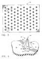
- FIG. 1is a plan view of an array of microelements that are pyramidal in shape, as constructed according to the principles of the present invention.
- FIG. 2is a perspective view of one of the pyramidal microelements of FIG. 1 .
- FIG. 3is an array of pyramidal microelements as according to FIG. 1 , with the addition of through-holes in the substrate, and channels along the sides of the microelements.
- FIG. 4is a perspective view of the pyramidal microelements of FIG. 3 .
- FIG. 5is a plan view of an array of microelements that have an overall cubic rectangular shape, as constructed according to the principles of the present invention.
- FIG. 6is a perspective view of one of the cubic rectangular microelements of FIG. 5 .
- FIG. 7is a plan view of an array of the cubic rectangular microelements of FIG. 5 with the addition of through-holes in the substrate.
- FIG. 8is a perspective view of one of the cubic rectangular microelements of FIG. 7 .
- FIG. 9is a plan view of an array of wedge-shaped microelements, as constructed according to the principles of the present invention.
- FIG. 10is a perspective view of one of the wedge-shaped microelements of FIG. 9 .
- FIG. 11is a plan view of an array of the wedge-shaped microelements of FIG. 9 with the addition of through-holes that penetrate through the microelement and through or into the substrate.
- FIG. 12is a perspective view of one of the wedge-shaped microelements having through-holes of FIG. 11 .
- FIG. 13is a plan view of an array of wedge-shaped microelements of FIG. 9 , in which a through-slot is located in the microelements, which penetrates through or into the substrate.
- FIG. 14is a perspective view of one of the wedge-shaped microelements having the through-slot of FIG. 13 .
- FIG. 15is a plan view of an array of microelements having an elongated triangular shape, as constructed according to the principles of the present invention.
- FIG. 16is a perspective view of one of the elongated triangular microelements of FIG. 15 .
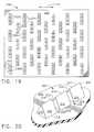
- FIG. 17is a plan view of an array of the elongated triangular microelements of FIG. 15 with the addition of through-holes in the substrate, and elongated channels along the surfaces of the triangular microelements.
- FIG. 18is a perspective view of one of the elongated triangular microelements of FIG. 17 .
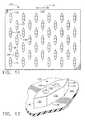
- FIG. 19is a plan view of an array of triangular-shaped wedge microelements that are grouped in closely-spaced arrangements, as constructed according to the principles of the present invention.
- FIG. 20is a perspective view of one of the closely-spaced triangular wedge microelements of FIG. 19 .
- FIG. 21is a plan view of an array of conical-shaped microelements, as constructed according to the principles of the present invention.
- FIG. 22is a perspective view of one of the conical microelements of FIG. 21 .
- FIG. 23is a plan view of a microelement array in which more than one microelement shape is constructed on the single substrate, as constructed according to the principles of the present invention.
- FIG. 24is an elevational view in partial cross-section of an array of microelements similar to those found in FIG. 23 , with the addition of through-holes or passageways to a reservoir structure below the main substrate.
- FIG. 25is a perspective view of multiple arrays of pyramidal-shaped microelements, as constructed according to the principles of the present invention.
- FIG. 26is a perspective view of multiple arrays of elongated pyramidal-shaped microelements, as constructed according to the principles of the present invention.
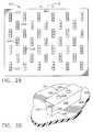
- FIG. 27is a plan view of an array of inverted wedge-shaped microelements, constructed as according to the principles of the present invention.
- FIG. 28is a perspective view of one of the inverted wedge-shaped microelements of FIG. 27 .
- FIG. 29is a plan view of an array of the inverted wedge-shaped microelements of FIG. 27 with the addition of through-holes in the microelements which penetrate through or into the substrate.
- FIG. 30is a perspective view of one of the inverted wedge-shaped microelements of FIG. 29 .
- FIG. 31is a plan view of an array of the inverted wedge-shaped microelements of FIG. 27 with the addition of through-slots in the microelements which penetrate through or into the substrate.
- FIG. 32is a perspective view of one of the inverted wedge-shaped microelements of FIG. 31 .
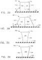
- FIG. 33is an elevational view in partial cross-section of a wedge-shaped microelement of FIG. 10 , in which the side walls are perpendicular with respect to the substrate plane.
- FIG. 34is an elevational view in partial cross-section of a wedge-shaped microelement similar to that of FIG. 10 , in which the side walls have an angular relationship that is not perpendicular with respect to the substrate plane.
- FIG. 35is a side elevational view of an inverted wedge-shaped microelement of FIG. 28 , in which the side walls are curved (i.e., concave).
- FIG. 36is a side elevational view of an inverted wedge-shaped microelement similar to that of FIG. 28 , in which the side walls are straight (i.e., flat).
- FIG. 37is a plan view of a microelement array as seen in FIG. 10 , with the addition of a non-woven backing material that is laminated to the original substrate.
- FIG. 38is a plan view of a plurality of microelement strips that are laminated onto a non-woven backing.
- FIG. 39is an elevational view in partial cross-section of a microelement array as seen in FIG. 10 , showing further details of the substrate and non-woven backing.
- FIG. 40is a perspective view mainly from above of a prior art array of microelements that are pyramidal in shape, and which exhibit very closely-packed density on the microstructure.
- FIG. 41is a side elevational view of two of the pyramidal microelements of the microstructure of FIG. 40 .
- FIG. 42is a side elevational view of two truncated or partially-pyramidal microelements of an array of such microelements that exhibit very closely-packed density on a microstructure, as constructed according to the principles of the present invention.
- the present inventionrelates to improving the health and condition, including the appearance, of human skin.
- the present inventioncomprises a system which utilizes an article of manufacture capable of selectively treating human skin and which can be modified depending upon the area of human skin which is to be treated, such as the face, hands, or feet; the type of treatment which is to be provided, such as skin refreshment; the type of adjunct compositions to be administered thereto, such as astringents, make-up, make-up remover, or at least one active or drug; or the respective frequency of use, as for example, daily in home use, or a single treatment by a skin care or medical professional in a clinic.
- skin enhancement treatmentis defined as “treatment of human skin with an article of manufacture as defined herein, wherein the surface of the skin is modified by controllably removing a selected number of skin layers or removing skin to a pre-determined depth, and optionally, delivering to the skin which has been treated, a skin enhancing composition, and/or removal therefrom of any unwanted substances.”
- Embodiments of the present inventionare directed to a wide range of skin enhancements, each enhancement based upon the type, configuration, and material, which comprises the microelements described herein.
- the systems of the present inventionoptionally comprise a composition that provides skin conditioning benefits.
- the stratum corneum of skincomprises layers of dead skin cells, which are part of the body's protective outer layer.
- This outermost layer of skin cellscan have a nominal thickness of from about one hundred (100) microns to about 250 microns for thick, durable skin areas, such as calluses, whereas normal, “thin” skin may comprise from about ten to about fifteen microns (10-15) thickness for its stratum corneum.
- One aspect of the present inventionrelates to the removal of the outermost layers (e.g., from 1 to 4 layers) of the stratum corneum.
- the articles of manufacture described hereinare capable of selectively removing a predetermined number of skin layers (also known as “exfoliation”). This is achieved by adjusting the configuration of the microelements and/or the distance from which the distal end of the microelements protrudes from a particular base element.
- the articles of manufacture of the present inventionmay have hollow or grooved microelements that can serve as passages through which a substance may flow. These passages allow for transport of a material to the skin, for example, an emollient, or, as in the case of removed cellular tissue, dirt, etc., a material from the skin or skin constituents.
- rubbingrepresents an action by which one of the microstructures of the present invention is placed upon skin and moved (or “scraped”) along the surface of the skin.
- the rubbing action(or “scraping” action) can be achieved manually, or by using a device.
- the microstructurecan be held by hand and manually rubbed against the skin, or the microstructure can be placed on a mechanical device that will, in turn, be used to move (or rub) the microstructure upon the surface of the skin.
- the articles of manufacture of the present inventioncomprise a base element (or “substrate”) onto which is affixed or deposed a plurality of microelements.
- a base elementor “substrate” onto which is affixed or deposed a plurality of microelements.
- the followingis a description of the base element and corresponding microelements.
- the articles of manufacture of the present inventioncomprise at least one base element having a first side and a second side. Onto the first side are affixed the microelements as described hereinbelow. Aside from providing a template or base structure onto which the microelements are affixed, the second side, or reverse side, may in turn comprise a handle or other means by which the article of manufacture can be held. In another embodiment, a substance can be deposed upon the second side, which allows the user to grasp, hold, or otherwise control the motion of the article using only the fingertips.
- the use of a material to provide a tactile surfaceis especially compatible for embodiments wherein the base element comprises a thin, substantially flexible material, such as paper or polymeric sheets.
- One embodiment of the present inventionincludes base elements which comprise flexible sheets, and the thickness of the sheets is determined by the desired degree of flexibility.
- the flexible sheetsare typically rigid enough to provide a template upon which the microelements can be affixed, but which are easily deformed to fit the contours of the skin surface.
- the base elements of the present inventionmay have any shape or configuration.
- one embodimentrelates to circular base elements, while another embodiment relates to rectangular base elements having a width and a length.
- rectangular base elementswill have a left edge and a right edge.
- the right edge of the base elementis defined herein as the edge along the right side of the base element when the second side of the base element is facing down (away from the observer) and the first side is facing the observer.
- the left edgeis oppositely defined herein.
- the second sidemay have at least one reservoir (or chamber) attached thereto (or constructed therewith) which contains a flowable (or “fluidic”) composition, or at least one reservoir or chamber for receiving material (e.g., hair, oils, skin cells) removed from skin.
- a flowable compositionor at least one reservoir or chamber for receiving material (e.g., hair, oils, skin cells) removed from skin.
- materiale.g., hair, oils, skin cells
- the hollow elementscan also be in register with a hollow element, channel, hole, or other passageway which modifies the microelements as described hereinbelow in a manner that allows a flowable composition to be delivered from the reservoir through a hollow element in the base element, through a tube or channel of the microelement, and onto skin.
- fluidor “fluidic” have a meaning that includes flowable liquids, flowable gases, relatively low-viscosity creams, flowable solutions that may contain solid particles, and the like.
- a “fluidic compound” or “fluidic material”specifically includes such liquids, gases, and solutions; these compounds or materials may comprise at least one active, a drug, or a skin conditioner, or other useful composition of matter; alternatively, the term “fluidic compound” can represent at least two actives, drugs, or the like, including both a biological active and a chemical active (in a single fluidic compound).
- the articles of manufacture of the present inventionfurther comprise a plurality of microelements, which are affixed to the first side or first surface of the base element.
- the “proximal end” of the microelementis defined herein as “the microelement end that is affixed to or in register with the base element.”
- the “distal end” of the microelementis defined herein as “the microelement end which comes into contact with skin, and which is the opposite end of the microelement from the proximal end.”
- the term “microelement”is defined herein as “an appendage for contacting skin which extends from the first side of the base element and is affixed thereto (or protrudes therefrom) at an attachment angle.”
- the term “microelement”refers to the entire element which contacts the skin and includes not only the appendage itself, but the attachment angle, any hollow elements or grooves, the density of the microelements as measured in the number of appendages per square centimeter, and any pre-disposed skin
- skinis defined herein as “animal skin, including human skin, plant skin or surfaces, and even other biological structures that may not have a true “skin” organ, such as tissue samples of either plant or animal origin.”
- the term “affixed” as it relates to attachment of the microelements to the base elementis defined as “held permanently to the first side of the base element.” Affixed microelements are neither removable nor detachable.
- the microelements of the present invention, as it relates to the term “affixed”can comprise any suitable embodiment.
- the microelements and base elementmay comprise a single uniform composition or the microelements may be extruded from the material comprising the first side.
- the microelementsmay be applied to the base element in a separate operation or manufacturing step, such as lamination to a non-woven substrate. Therefore, the microelements can be fashioned and applied in any manner the formulator desires which achieves the desired microelement density or configuration.
- suitable microelement configurationsinclude those described in U.S. patent applications: U.S. Ser. No. 09/580,780, U.S. Ser. No. 09/580,819, and U.S. Ser. No. 09/579,798 all filed May 26, 2000; U.S. Ser. No. 09/614,321 filed Jul. 12, 2000 all of which are commonly-assigned to The Procter & Gamble Company, and which are incorporated herein by reference.
- microelement densityis defined herein as “the number of microelements per square centimeter of base element surface.”
- the appendages that comprise the microelementsmay be of any configuration that is capable of providing the desired skin enhancement.
- One embodiment of the present inventionrelates to a plurality of appendages in the form of regular conical appendages. Regular conical appendages have a circular proximal end and a pointed or rounded distal end.
- Another embodimentrelates to inverted conical microelements, in which the appendages are conical appendages affixed to the base element at the tapered end and the circular base comprises the distal end.
- Rod-shaped appendagesare circular or elliptical rods having a uniform circumference along the entire length.
- Planar appendagesare cubes or cubic rectangles (or open boxes) wherein the length and width are uniform (but not necessarily equal to one another) throughout the height of the appendage and the distal end comprises a plane, such as a square, rectangle, or trapezoid, in which the plane is parallel to the base element or at an angle thereto.
- Wedge-shaped appendageshave a rectangular proximal base that tapers to a line segment, which preferably has the same length as the length of the rectangular base. Some wedge-shaped appendages have an inverted appearance.
- Pyramidal appendagesmay comprise bases which have three or four sides at the proximal end base, and which taper to a point or rounded top at the distal end.
- the wedge-shaped appendagesmay have a triangular section removed therefrom that acts to facilitate the removal of skin hair follicles.
- the appendages of the present inventionmay also be coiled having any number of turns from the proximal end to the distal end.
- microelement angleis defined as the “angle at which the appendage of the microelement protrudes from the base element.”
- a microelementwhich is affixed perpendicular to the base element, has a microelement angle of 90°.
- the microelements of the present inventioncan be affixed to the base element at any angle from about 30° to about 90° (perpendicular).
- the microelementscan be affixed to the base element at any angle from about 30° to about 150°.
- microelements which are not perpendicular to the base elementmay be angled toward any edge of a rectangular or square base element, or be perpendicular to the tangent of any point along the circumference of a circular base element.
- the microelements of the present inventionmay also comprise hollow elements or contain grooves.
- Hollow elementsare typically disposed along the longitudinal axis of the appendage portion of the microelement and are in register with a corresponding hollow element or passageway at the base element. Grooves or indented elements occur along the surface of an appendage and serve, like hollow elements, to move material toward the skin or remove material therefrom.
- embodiments which provide a skin conditioning composition to the skinmay use a series of hollow elements to deliver the composition from at least one reservoir to the skin.
- natural facial oilsmay be carried away from the skin surface by capillary action though hollow elements or by inductive flow along grooves on the surface of the appendages.
- microelements of the present inventionmay range from absolute rigid (inflexible) to flexible.
- flexibleis defined herein as “during use against skin, the distal end of an appendage is bent or deformed up to 90° from the microelement angle as defined herein above.”
- a perpendicular appendage which is bent 90°is therefore parallel with the base element.
- An appendage having a microelement angle of 45°can be deformed or bent to an angle of 135°.
- the microelements of the present inventionmay have a protrusion distance of up to 150 microns from the surface of the base element.
- protrusion distanceis defined herein as “the distance from distal end of the microelement along a line parallel to the base element.” For perpendicular microelements the length of the appendage and the protrusion distance are equivalent.
- a microelement having a microelement angle, for example, of 30°will have a protrusion distance equal to one half the length of the appendage.
- One embodiment of the present inventionrelates to microelements having a protrusion distance of about 1-100 microns. Another embodiment relates to protrusion distances of about 1-50 microns. Further embodiments encompass microelements wherein the appendages have protrusion distances from about one to about twenty (1-20) microns, whereas other embodiments include protrusion distances of from about five to about twenty (5-20) microns and from about four to about twenty (4-20) microns, as well as embodiments from about four to about ten microns (4-10). Other embodiments comprise no range of protrusion distances but have discreet distances such as, for example, a 4-micron embodiment, a 5-micron embodiment, or a 10-micron embodiment.
- the microelements of the present inventionmay comprise an appendage, which has flexible elements and rigid elements, for example, an appendage which has a rigid portion extending from about the middle of the element to the proximal end and a flexible portion extending from about the middle of the element to the distal end.
- Articles of manufacture which are composites of several materialsmay comprise a thin flexible base element onto which are deposed rigid, inflexible microelements.
- the articles of manufacture of the present inventionmay comprise a multitude of arrays, each array comprising the same or different types or sizes of microelements, in which the various attributes of the microelements, including microelement density, appendage type, microelement angle, hollow elements vs. solid elements with or without grooves, degree of flexibility, protrusion distance, etc. may vary from array to array or within a single particular array.
- arrayis defined as “multiple microelements in a pattern.”
- certain array elementscollectively may be separated from another array by a distance which is greater than the distance between the microelements which comprise the first array.
- arraysmay contain different types of microelements which all have the same spacings. The distance between microelements along the edge of two separate and distinct arrays may be greater than the distance between two microelements, which are members of the same array.
- several different microelement shapes or protrusion sizesmay exist in a single array in which all individual elements are spaced-apart from one another in a consistent manner throughout the entire structure.
- the microelementspreferably have a length and shape that will tend to scrape skin cells (typically dead or loose skin cells) from the upper surface of the stratum corneum, while at the same time will not tend to penetrate entirely through the stratum corneum layer.
- the characteristic of the microelements to not cut or penetrate entirely through the stratum corneumis further enhanced by directing the user to move the “patch” or microstructure in only one direction (or in a single line that represents a back and forth direction), so that the “sharper” edges of the microelements do not tend to cut or plow into the skin upper layers; instead, these sharper edges merely assist in scraping away the skin cells.
- some of the microelementshave shapes that also assist in accumulating the skin cells (as well as other foreign substances found on the skin surface) once they have been scraped loose.
- FIG. 1illustrates a microstructure array generally designated by the reference numeral 10 containing multiple microelements 12 that are situated on a base or substrate 14 .
- each “column” of microelements 10is offset from the next, adjacent column of similar microelements.
- each of the columnscould be made to be identical to one another, if desired, and the offset could be removed.
- FIG. 2illustrates in a magnified view one of the microelements 12 , which has the appearance of a four-sided pyramid.
- Each side wall of the pyramidis designated at the reference numeral 20 , and the seam or “corner” between sides is located at the reference numeral 22 .
- the pyramid's peakis illustrated at 24 , and the base line of each of the sides is located at 26 , where it meets the substrate 14 .
- This array 10 of microelementsis very useful in skin preparation by forming it into a patch that can be held by a human hand, and placed against a particular area of skin and then rubbed in a straight back and forth motion (or perhaps in a circular motion, if desired).
- the microelements 12will tend to remove skin cells that will accumulate in the planar spaces between the individual microelements 12 . Since the skin cells that are removed do not become airborne, the microstructure array or patch 10 is a great improvement over the previously available mechanical scrubbers. Instead of knocking skin cells loose, the invention of FIG. 1 will trap the loose skin cells, which will then be disposed of along with the microstructure array 10 .
- the microstructure array 10is very useful for an exfoliation of the skin, which in essence will pre-treat the skin for a later application of a conditioner substance, if desired.
- the array structurecan also remove and collect foreign substances or even hair that are found on the surface of the skin while the microelements are rubbed along the skin surface. Once the area between the pyramidal microelements 12 becomes “full” of removed or “loose” skin cells and other substances, then this microelement array 10 essentially loses its functionality.
- the amount of material (including the loose skin cells) that is removed by use of the microelement array 10is controlled by the height of the individual microelements 12 and the spacings therebetween. This allows fairly precise control over the number of layers of skin cells that are removed.
- the array or patch 10will correctly perform its functions of scraping and removing skin cells without regard to the direction of movement of the patch 10 with respect to the orientation of the individual microelements 12 .
- these microelements 12are omnidirectional in operation, and all directions are preferred, or even “predetermined.”
- Other embodiments of the invention described beloware not omnidirectional, and instead are unidirectional or bi-directional in nature with respect to the orientation of their individual microelements.
- the “precise control” noted above in connection with removal of the number of layers of skin cellsis a “self-limiting” feature, in that the substrate-microelement combination (i.e., the microstructure patch 10 itself) will only remove a substantially predetermined quantity of these skin cells and materials before becoming “full,” after which the patch 10 essentially will not remove any further skin cells/materials.
- the systemis basically fool-proof! Even if the user, either out of ignorance or exuberance, attempts to continuously re-use the patch, it will not further “scrape” the user's skin. After the patch 10 has accumulated the maximum amount of material that it can nominally hold, any additional skin cells removed by such further attempts to scrape the skin will be minuscule in quantity, and such further scraping attempts are essentially futile.
- microstructure 10Another feature of the microstructure 10 is its capability for use in applying a conditioner or other type of compound that is in the form of a liquid or a cream. Just after the microstructure patch 10 has “cleansed” (exfoliated) an area of skin, the skin's surface will be smoother and mostly free of foreign substances. It is the perfect time to apply a fluidic compound, such as a conditioner, to the skin.
- the conditionercould enhance the health of the skin, or be in the form of make-up, for example. It also could be some type of topical drug or other active, if desired.
- the other microstructures described belowwill also lend themselves well for this type of topical application of a fluidic compound to skin.
- a further feature of the microstructure 10is its capability for a compound to be applied onto the substrate 14 and/or microelements 12 in advance of its placement against an area of skin.
- the microstructure patch 10When the microstructure patch 10 is placed onto the skin, it will impart some of this compound onto the same area of the skin that is being cleansed, or exfoliated—this will essentially occur simultaneously.
- the other microstructures described belowwill also lend themselves well for this type of simultaneous delivery of a fluidic compound to the same area of skin that is being exfoliated.
- the embodiments described below which include through-holes in the substratemay not be the first choice for this methodology of composition delivery, but such devices certainly could be used in this manner, if desired.
- the compound that is pre-applied to the surface of the microstructure 10could be placed either by the user, or at the time of manufacture of the microstructure 10 .
- FIG. 3illustrates a similar microelement array, generally designated by the reference numeral 30 , in which through-holes and channels are added.
- the base or substrate 34includes a plurality of through-holes 36 that are positioned proximal to the base of the individual pyramidal microelements 32 .
- These through-holes 36can either penetrate through the entire substrate 34 , or can penetrate partially into the substrate and connect to passageways that may run in a direction perpendicular to the through-holes, and make common connections between many of the through-holes.
- FIG. 4further details are visible, in which the side walls 40 of the pyramidal microelement 32 are seen to have grooved channels 38 which connect to the through-holes 36 .
- the edges of the side walls 40are at reference numeral 42 , the individual base lines of the pyramid are at 46 , and the peak of the pyramid is at 44 .
- the array 30 of multiple pyramidal structures at 32all have a through-hole adjacent to each side of the pyramid.
- there could be fewer through-holes 36 per pyramidal microelement 32if desired.
- some of the pyramidal microelements 32 in the arraycould have no adjacent through-holes, if desired.
- Such microelements(or others in the array) could also forego the channels 38 .
- FIGS. 3 and 4The structure of FIGS. 3 and 4 is useful to perform a simultaneous exfoliation and conditioning step. While the array or “patch” 30 is rubbed along the skin, the removed or loose skin cells will accumulate in the open spaces between the individual pyramidal microelements 32 , which will prepare the skin for any type of conditioning that will then be placed upon that skin surface. Even after the “spacing areas” between the microelements 32 become essentially full of loose skin cells and oils or other substances found on the skin surface, at least one active or conditioner can nevertheless be delivered through the grooves or channels 38 by use of a capillary force.
- the loose skin cellswill not necessarily be tightly jammed along the surfaces of the pyramidal microelements 32 , and therefore, should not become a significant obstacle to the delivery of the active or conditioner along the channels or grooves 38 .
- the capillary forcewill work to the advantage of delivering a conditioner or active, especially in partially-locked grooves or channels 38 .
- the array or patch 30will correctly perform its functions of scraping and removing skin cells without regard to the direction of movement of the patch 30 with respect to the orientation of the individual microelements 32 .
- these microelements 32are omnidirectional in operation, and all directions are preferred, or even “predetermined.”
- FIG. 5Another microelement shape is illustrated in FIG. 5 , comprising an array 50 of “cubic rectangular” microelements at 52 .
- These microelements 52have a cup-like shape which has the appearance of a topless, hollow or open cube-like or box-like structure after one of the cube's (box's) side walls have been removed. This can be clearly seen in the perspective view of FIG. 6 . (It will be understood that the “cube-like structure” 52 does not have identical length, width, and height outer dimensions, and thus is not really a geometric cube. In that respect, the term “box-like” or “box” is more descriptive.)
- the individual columns of microelements 52can be offset on the substrate 54 , as seen in FIG. 5 .
- each of the individual columns of these microelements 52could be identical, thereby eliminating any offset, if desired.
- the microstructure or “patch” 50is rubbed back and forth substantially along the direction designated by the letter “D” (which is a preferred, predetermined direction).
- Dwhich is a preferred, predetermined direction.
- the open cup-like areawill easily collect the loose skin cells and other foreign substances on the surface of the skin.
- the “open” area that will collect these cellsis easily seen at 68 in FIG. 6 .
- FIG. 6shows further details of the individual microelement 52 , which has a “back wall” 62 , a pair of “side walls” 60 , a “front edge” at 64 on each of the side walls 60 , and a base line 66 along the bottom of the side walls 60 .
- the amount of skin cells that can be collected by this structure 50will depend upon the height of the individual microelements 52 , as well as the spacings between such microelements on the substrate 54 .
- the cup-like shape of the individual microelements 52provides even better control over the quantity of material that is to be removed due to the rubbing action. Factors that impact the skin cell sizes to be removed (and the overall quantity of material to be removed) include the height of the walls 60 and 62 , the open distance between edges 64 (i.e., the area 68 ), and the sharpness of the edges 64 themselves.
- FIG. 7illustrates a similar array of microelements, designated by the reference numeral 70 .
- Each individual microelement 72has a similar appearance to the open box-like microelements 52 of FIGS. 5 and 6 , however, a through-hole 76 has been added within the “cuplike” area of the microelement 72 .
- These holestypically would run completely through the base or substrate 74 , although they could instead extend only partially into the substrate to connect to some type of internal channels. In that manner, these holes could become (or connect to) passageways of any shape, diameter, or length.
- the microstructure array 70could be formed into a “patch” that is applied to skin and rubbed in a back and forth manner substantially in the direction “D” indicated on FIG. 7 (which is a preferred, predetermined direction).
- FIG. 8shows further details, in which there are two side walls 80 , a back wall 82 , two “front” edges 84 , a base line 86 for each of the side walls 80 , and the through-hole 76 that is proximal to the interior area of the microelement 72 .
- the microstructure 70 disclosed on FIGS. 7 and 8can be used to simultaneously exfoliate the skin surface while delivering some type of active that will condition the skin, or otherwise treat the skin. Such systems can both exfoliate and deliver in a single operation.
- FIG. 9illustrates an array 100 of wedge-shaped microelements 102 mounted onto a base or substrate 104 .
- each column of microelements 102can be offset from the adjacent column, as illustrated on FIG. 9 .
- the columnscould alternatively be made identical to one another, in which there would be no offset.
- a further alternativecould arrange several columns with various offsets before the microelement pattern repeats, or the offsets could be substantially random so that there is no repetitive pattern.
- the wedge-shaped microelement 102is illustrated in greater detail in the perspective view of FIG. 10 .
- the top of the structureis at 114 , and there are two elongated side walls 112 and a pair of converging side walls 110 that, at their line of convergence, form a cutting edge 116 .
- the relatively sharp edge 116is not purposefully used to “cut” skin in the exfoliation methodology described in this patent document. Instead, the overall wedge shape of the microelement 102 is provided as a more substantial structure than some of the other embodiments described herein. It also is probably easier to manufacture than the microelements described earlier, in FIGS. 1-8 .
- the relatively sharp edges 116will not be used to cut into the skin when the patch 100 is moved in this manner along the line “D.”
- the microelement patch or array 100is designed to exfoliate the skin and accumulate skin cells and other foreign substances that have accumulated on the skin. The amount of removed skin cells and foreign substances that will be accumulated on the microelement array 100 depends upon the height of the individual microelements 102 and the spacings therebetween.
- FIG. 11shows a similar wedge-shaped microstructure array at 120 , which has individual wedge-shaped microelements 122 that have two separate through-holes at 126 .
- the microelements 122are all mounted on a base or substrate 124 .
- the columns of microelements 122are somewhat different from one another, in that they are offset from one another in adjacent rows. This need not be the case, and alternatively the columns could be identical to one another to eliminate any offset, if desired. Again, alternatively there could be several columns with various offsets before the microelement pattern repeats, or the offsets could be substantially random so that there is no repetitive pattern.
- FIG. 12shows further details of the individual microelement 122 , in which a top surface 134 and elongated side walls 132 are exhibited, along with converging side walls 130 that come to a sharp edge 136 .
- a base line 138is also illustrated as the junction between the microelement 122 and the substrate 124 .
- the through-holes 126are created to penetrate entirely through the microelement 122 , and preferably will also penetrate entirely through the base 124 , although the holes 126 can become passageways that do not entirely penetrate through the base or substrate, but instead connect to some type of perpendicular runs or passageways, if desired. Since there are two separate holes 126 per microelement 122 , it is possible to simultaneously deliver two different actives (one per hole in a single microelement) in a single operation, if desired.
- the microelements 122are designed to perform both an exfoliation and delivery procedure in a single step. In this particular structure, it can almost be guaranteed that there will be a lack of build-up of dead skin and other foreign matter within the delivery holes or passageways 126 . Even if some of this foreign matter or dead skin cells accumulates in these passageways 126 , a capillary action may result and accomplish delivery of at least one active or drug through the passageways 126 onto the surface of the skin.
- FIG. 13illustrates a microstructure array designated by the reference numeral 140 that contains a large number of individual wedge-shaped microelements 142 that are mounted to a base or substrate 144 .
- These wedge-shaped microelements 142contain a through-slot 146 , through which at least one active or drug can be delivered to a skin surface after an exfoliation operation has taken place.
- the microelement array or patch 140will preferably be placed on the skin surface and rubbed in a back and forth manner substantially along the direction “D” (which is a preferred, predetermined direction) to remove skin cells and other foreign substances from the skin surface. The amount of material removed from the skin surface will depend upon the height of the individual microelements 142 and the spacings therebetween.
- FIG. 14shows greater details of an individual microelement 142 , showing a top surface 154 , side walls 152 , converging side walls 150 that come to a relatively sharp edge 156 , and a base line 158 where the microelement 142 adjoins the base or substrate 144 .
- the through-slot 146can provide a larger cross-sectional area for delivery of at least one active or drug to the skin surface, as compared to the microelement 122 of FIG. 12 .
- the actual dimensions of the microelement 142could be either larger or smaller than similar microelements 122 illustrated on FIG. 12 .
- Both sets of microelements 122 and 142are relatively simple to construct, although the ones with the through-slot 146 may be somewhat easier to construct as compared to constructing multiple smaller through-holes 126 .
- the patch or array 140can be used for a combinational step of exfoliation and delivery of at least one active, in a similar fashion to that described in some of the earlier embodiments.
- Other similar shapes of wedge-shaped structurescould easily be constructed without departing from the principles of the present invention.
- FIG. 15discloses an array or patch 160 of triangular-shaped wedge microelements 162 , mounted on a base or substrate 164 .
- each of the microelements 162consists of an elongated triangular shape, having a pair of triangular side walls 170 , a pair of sloped elongated side walls 172 , a top edge 174 , and a pair of base lines 178 .
- the junction between the triangular end walls 170 and the rectangular but sloped side walls 172is designated at the reference numeral 176 .
- the peak of the triangleis illustrated at 174 , which is only one point along the top edge 174 of the microelement 162 .
- These triangular-shaped wedgescan be useful in an exfoliation procedure, and preferably will be placed on skin in the form of a patch and then rubbed back and forth over the skin substantially in the direction “D” (which is a preferred, predetermined direction).
- Dwhich is a preferred, predetermined direction.
- the amount of loose skin cells that are removed (and the amount of any additional foreign substances removed)will depend upon the overall height of each of the microelements 162 and the spacings therebetween.
- the individual columns of microelementscan be offset from one another in adjacent columns, as seen in FIG. 15 . Alternatively, the columns could be identical to one another, without any offset. Another alternative could arrange several columns with various offsets before the microelement pattern repeats, or the offsets could be substantially random so that there is no repetitive pattern.
- FIG. 17discloses a similar microelement array 180 , which has triangular-shaped wedges as individual microelements 182 that are placed or are formed upon a base or substrate 184 .
- the “patch” 180there are multiple through-holes 186 and channels 188 for placing at least one active on the skin.
- FIG. 18shows the channels 188 and holes 186 in a magnified view, in which the holes 186 would typically be designed to penetrate entirely through the substrate 184 ; however, such holes 186 could only partially penetrate the base if they connect to some other type of passageway within the base structure itself.
- the triangular shape of the microelement 182is seen on FIG. 18 along the side wall 190 , which connects to sloped, rectangular side walls 192 along edges 196 .
- a top edge 194exists between the two triangular side walls 190 , and a base line 198 marks the line between the microelement 182 and the substrate 184 .
- FIG. 18there are three separate channels 188 in the surface of the elongated side wall 192 .
- fewer channelscould be utilized, if desired, or even more numerous channels could be used.
- These channels 188lend themselves well for capillary action to allow at least one active to flow through the holes 186 and along the channels 188 onto a skin surface, even after the areas between the microelements 182 become substantially full of dead skin cells and other foreign substances.
- the triangular wedge structures of both FIGS. 16 and 18are designed to essentially scrape away dead skin cells without penetrating the skin itself. This is accomplished by moving the microelement patches 160 or 180 in a back and forth manner substantially in the direction “D” as shown on FIGS. 15 and 17 .
- the microelement patcheswere to be moved in a different direction, particularly one that was perpendicular to the line “D” (which is a preferred, predetermined direction), then it is quite likely that the skin would be cut and penetrated. This has much usefulness, however, that concept is not part of the present invention. Instead, that type of methodology is disclosed in a companion patent application, filed on Sep. 14, 2001, under Ser. No. 09/952,391, that is also assigned to The Procter & Gamble Company, and having the title “Microstructures for Delivering a Composition Cutaneously to Skin.”
- FIGS. 19 and 20Another refinement of the triangular-shaped wedge is illustrated on FIGS. 19 and 20 .
- a microstructure array or patch 200is illustrated as containing multiple wedge-shaped microelements 202 that are placed upon, or are formed thereon, a base or substrate 204 .
- each of the microelements 202is comprised of three separate triangular-shaped wedges, each having a space therebetween at 206 .
- the three sections of the triangular-shaped wedge 202includes a triangular-shaped side wall 210 , a pair of rectangular, sloped side walls 212 , a top edge 214 , and a base line at 216 where the microelement 202 joins the substrate 204 .
- Each of the three wedge shapesis separated by a space 206 , in which a center triangular wedge shape is surrounded on both sides by a second, outer similar wedge shape, and spaced apart from each of these outer wedge shapes by the spacing area 206 .
- the “new” spaces 206provide more trapping area between the closely-spaced wedges of the microelement 202 . Therefore, a further amount of material should accumulate within these spaces, thereby trapping more dead skin cells and other foreign substances for a given microelement array or patch 200 . As in the case of these embodiments described above, the amount of material that will be removed and then accumulated from the skin surface will depend upon the height of the microelements 202 and the spacings therebetween. In this new structure of FIGS. 19 and 20 , this will also depend upon the spacings 206 between the individual triangular wedges of the individual microelement 202 .
- the preferred use of the array or patch 200is to apply the patch directly to the skin, and then rub the patch in a back and forth manner along the skin surface substantially in the direction “D” as seen on FIG. 19 (which is a preferred, predetermined direction).
- This particular designexfoliates quite well, but is not designed to also apply an active at the same time.
- through-holes and channelscould be added to this structure, if desired, although that type of structure would probably be easier to construct when using the shape disclosed in FIG. 18 for the microelement 182 .
- FIG. 21illustrates a microstructure array 220 that has multiple cone-shaped microelements 222 that are placed upon or constructed on a base or substrate 224 .
- the individual microelements 222are illustrated in greater detail in FIG. 22 , in which each conical microelement 222 has a curved side wall 230 , a peak 232 , and a circular base “line” at 234 .
- the conical shape of the microelement 222could be somewhat truncated so that it does not come to a perfect point at 232 .
- One advantage of having the curved side wall 230is that it will more easily de-mold, thus simplifying fabrication.
- the individual columns of the conical microelements 222can be offset from one another for such adjacent columns if desired, as viewed in FIG. 21 .
- each of the columns of microelementscould be identical to one another, with no offset.
- Yet another alternativecould arrange several columns with various offsets before the microelement pattern repeats, or the offsets could be substantially random so that there is no repetitive pattern.
- the conical microelements 222 on the array or patch 220can be used for exfoliation in a manner as described above for other shapes of microelements.
- the direction of motion of the array or patch 220is not important with respect to removing the skin cells or other foreign substances from the skin surface.
- the microstructure patch 220is similar to the patches 10 and 30 disclosed in FIGS. 1 and 3 .
- the amount of dead skin cells and other substances that are accumulateddepends upon the height of the individual microelements 222 as well as the spacings therebetween.
- the array or patch 220will correctly perform its functions of scraping and removing skin cells without regard to the direction of movement of the patch 220 with respect to the orientation of the individual microelements 222 .
- these microelements 222are omnidirectional in operation, and all directions are preferred, or even “predetermined.”
- FIG. 23illustrates a microstructure array generally designated by the reference numeral 240 that contains more than one microelement shape upon its substrate 242 .
- the different shapesare grouped in sub-arrays, which are designated by the reference numerals 250 , 252 , 254 , 256 , and 258 .
- These multiple shapes on a single base or substratecould all be the same height, or if desired, could be of different heights.
- the overall width of the array or patch 240is designated by the dimension “W”, which could be of any size necessary for a particular application.
- the left-hand array 250consists of multiple cup-shaped microelements 52 , which were earlier described in reference to FIGS. 5 and 6 . As seen in FIG. 23 , these “open-box” or “cup-like” microelements 52 are facing to the left, which means that they would tend to accumulate skin cells when the array or patch 240 is moved toward the left along the arrow “D” (which is a preferred, predetermined direction).
- the width of this array 250is about 1 ⁇ 6 W in the illustrated embodiment of FIG. 23 ; however, the width or array overall shape (i.e., it could be non-rectangular) could be easily varied, as desired.
- a similar array of cup-like microelements 52is arranged along the right-hand side (as seen in FIG. 23 ) in the array 258 .
- These open-box microelements 52would tend to accumulate skin cells when the microelement array or patch 240 is moved toward the right along the arrow “D” (which is still a preferred, predetermined direction).
- the width of this array 258is also about 1 ⁇ 6 W in the illustrated embodiment of FIG. 23 , but this too could be easily varied.
- the microelements in the arrays 252 and 256are illustrated as being the wedge-shaped elements 102 that were described above in reference to FIGS. 10 and 11 .
- the middle array 254is composed of the pyramidal microelements 12 that were described above in reference to FIGS. 1 and 2 .
- the width of the arrays 252 and 256are each about 1 ⁇ 6 W in the illustrated embodiment of FIG. 23 ; however, the width or array overall shape (i.e., it could be non-rectangular) could be easily varied for either of these arrays, as desired.
- the width of the middle array 254is about 1 ⁇ 3 W in the illustrated embodiment of FIG. 23 ; however, as noted above, the width or array overall shape (i.e., it could be non-rectangular) could be easily varied, as desired.
- the pyramidal-shaped microelements 12would provide a “fine” treatment and remove the smaller skin cells
- the wedge-shaped microelements 102 of the arrays 252 and 256would provide a “medium” treatment and thereby remove somewhat larger skin cells.
- the “end” arrays 250 and 258 that are composed of the cup-shaped (or open box) microelements 52would provide a “coarse” treatment of the skin, and tend to remove the larger skin cells.
- each individual area of the multiple-shaped array or patch 240would tend to remove different sized skin-cells, thereby accomplishing a removal of at least most of all of the skin cells up to a certain depth into the stratum corneum.
- the types and sizes of skin cells that are removedcould also be controlled by changing the height of some of the microelements of different shapes, if desired. As noted above, however, even if all of the microelements were of the same precise height, each of these array areas would tend to accumulate different sized skin cells.
- a microelement patchcould be composed of any one shape of microelements, or could be comprised of several different shapes on a single substrate or patch structure, without departing from the principles of the present invention.
- the microelements disclosed hereincould be of all the same height, or of different heights on the same substrate or patch, without departing from the principles of the present invention.
- minor modifications to the shapes disclosed in the drawingsare contemplated by the inventors, and would still fall within the principles of the present invention.
- the microelement arrays or patches that contain through-holes or through-slotsneed not have such through-holes or through-slots for each and every one of the individual microelements that make up the array.
- the passageways that flow through the microelements (or adjacent thereto)could be constructed on only one-half of the microelements, if desired, while still achieving most of the results that would otherwise be achieved if such through-holes or through-slots were found at each of the microelements.
- the holes or slotscould be varied in size or diameter to either reduce or increase the amount of fluidic material that flows therethrough. All of these variations are contemplated by the inventors, and would fall within the principles of the present invention.
- FIG. 24is a side elevational view in partial cross-section of a microstructure that contains an array of different shaped microelements and a corresponding substrate, designated at the reference numeral 260 , as well as an underlying reservoir structure designated by the reference numeral 270 .
- the array of microelements 260is illustrated as having a set of pyramidal microelements 32 having grooves or channels 38 along the sides of the pyramid shapes, and a set of wedge-shaped microelements 122 having through-holes 126 .
- the base or substrateis designated at the reference numeral 262 .
- the through-holesactually travel all the way through both the microelements and the substrate 262 to form passageways, and these passageways are depicted in two groups.
- the first groupis a combination of the grooves or channels 38 in the pyramidal microelements 32 that are connected to the through-holes 264 , to form a common set of passageways that extend from the bottom surface of the base or substrate 262 through the top surface of this substrate 262 and are in communication with the channels or grooves 38 .
- the second set of passagewayscomprises a set of through-holes 266 that are in communication with the microelement through-holes 126 of the wedge-shaped microelements 122 . These through-holes 126 and 266 must be in registration with one another to form complete passageways from the top of the microelement 122 to the bottom of the substrate of 262 . Naturally, there could be some horizontal runs that connect similar passageways, if desired.
- the bottom portion 270 depicted in FIG. 24includes a reservoir structure that has a bottom wall at 272 and a reservoir area or volume at 276 that is bounded by the side walls of the reservoir at 274 . Multiple such compartments or chambers can be constructed to house multiple actives.
- the upper portion of this reservoir structure 270would typically be planar, as depicted at the reference numeral 278 , and would make contact against the bottom surface at 268 of the microstructure/substrate apparatus at 260 .
- the reservoir 276be in communication hydraulically or pneumatically with the passageways 264 and 266 , thereby allowing a fluidic drug or other active to reside within the reservoir confines at 276 until used, and then for the fluidic drug or active to be directed through the passageways 264 and 266 to the upper surface of the microelements 32 and 122 .
- FIG. 25illustrates a variation of the pyramidal microelements on a patch or array, generally designated by the reference numeral 280 .
- Several columns of the pyramidal microelementsare illustrated, in which the columns are at 284 , and are composed of individual pyramidal microelements 12 .
- These columns 284 of microelementsare all built upon a planar substrate 282 of the array or patch 280 . As can be seen in FIG. 25 , there is no substantial space between individual microelements 12 within an individual column 284 .
- the array/patch 280will be placed upon skin and moved in a back and forth manner substantially along any line. Similar to the patch 10 , the array or patch 280 will correctly perform its functions of scraping and removing skin cells without regard to the direction of movement of the patch 280 with respect to the orientation of the individual microelements 12 . In other words, these microelements 12 are omnidirectional in operation, and all directions are preferred, or even “predetermined.”
- FIG. 26illustrates a similar arrangement of microelements, and includes multiple columns of pyramidal elongated microelements; its overall structure is designated by the reference numeral 290 .
- the upper surface of the base or substrate 292includes multiple columns 294 of elongated pyramidal microelements 162 , in which there is no substantial space between each of the microelements 162 within a single column 294 .
- the individual columns 294are spaced-apart from one another so that a planar area that is relatively open at the start is made available, at the areas designated by the reference numeral 296 . These open areas 296 will receive the skin cells and other foreign substances on skin when the array/patch structure 290 is used to exfoliate the skin. In a preferred mode of use of the array/patch 290 , the patch 290 will be placed upon skin and moved in a back and forth manner substantially in the direction of the arrow “D” (which is a preferred, predetermined direction).
- FIG. 27illustrates an array of microelements, in which the array is generally designated by the reference numeral 300 .
- the individual microelements 302are arranged in columns on a substrate 304 .
- the columnscan have an offset of the microelements, as illustrated on FIG. 27 .
- the individual columns of microelements 302could be identical to one another, without any offset.
- FIG. 28depicts one of the individual microelements 302 in greater detail.
- This microelement 302has a shape that is something like an inverted curved wedge, or an inverted conical shape, as exhibited by one of its end walls 310 .
- the curved edges of end wall 310are depicted at 316 , and a curved elongated side wall is depicted at 312 .
- the top of the inverted wedge shapeis depicted at 314 , while the base line at 318 illustrates the point or line where the microelement 302 meets the substrate 304 .
- This inverted wedge shapeis quite useful for exfoliation of skin, and can accumulate loose or dead skin cells and other foreign materials from the skin by use of a back and forth motion substantially along the line “D” (which is a preferred, predetermined direction).
- the height of the individual microelements 302 and the spacings therebetweenwill determine how much material will be removed from the skin surface.
- FIG. 29illustrates an array 320 of similar inverted wedge-shaped microelements 322 , which are mounted upon a substrate 324 .
- the microelements 322each include two through-holes 326 , which are designed to pass one or more fluidic drugs or actives from one or more reservoirs to condition the skin after exfoliation.
- FIG. 30illustrates an individual inverted wedge microelement 322 in greater detail.
- the end wall 330shows the overall shape of the inverted wedge (or inverted conical shape), which has two curved edges at 336 that adjoin the end wall 330 to adjacent elongated side walls 332 .
- a top surface at 334is illustrated as having the two through-holes 326 , while a bottom base line 338 shows the line where the microelement 322 joins the substrate 324 .
- This inverted wedge-shaped microelement 322can be used in a single operation for both exfoliation and for delivering at least one active to the skin surface.
- This activecan be used to condition the skin just after many of the dead or loose skin cells have been removed.
- FIGS. 31 and 32An alternative structure for the inverted wedge microelement is illustrated in FIGS. 31 and 32 .
- FIG. 31an array 340 of microelements 342 is depicted on a substrate 344 .
- Each of the microelements 342contains a through-slot 346 , which can be seen in greater detail in the perspective view of FIG. 32 .
- the microelement 342can be seen to have an inverted wedge shape (or inverted truncated conical shape) as exhibited by its end wall at 350 .
- This end wall 350is adjoined to adjacent elongated side walls 352 by curved edges 356 .
- the top surface of the microelementis viewed at 354 , while its bottom base line 358 illustrates the junction between the microelement 342 and the substrate 344 .
- the through-slot 346can be used to deliver at least one active to skin, thereby making the array/patch 340 useable for both exfoliation and active delivery in a single operation.
- the array/patch 340is placed on skin and then moved in a back and forth direction substantially along the line “D” (which is a preferred, predetermined direction).
- FIG. 33illustrates the wedge-shaped microelement 102 from its “sharp” end in an elevational view.
- the two converging sides 110are seen to form a relatively sharp edge at 116 , which travels vertically from the top of the substrate/base 104 to the top surface 114 of the microelement 102 .
- the angle “A” between the substrate top surface at 104 and the side wall 112is clearly visible. On FIG. 33 , this angle “A” is approximately 90°, and therefore forms a perpendicular angle.
- FIG. 34shows an alternative shape for a wedge-shaped microelement designated by the reference numeral 402 .
- This wedge-shaped microelementhas a similar appearance from above to that of the wedge-shaped microelement 102 , except that its elongated side walls are not formed by a perpendicular angle to the substrate.
- the substrate 404is joined to the outer wall that is elongated along the side of the microelement (i.e., the wall 412 ) by an angle “A” that is greater than 90°. Its complimentary angle is illustrated at “B.” Angle B is between 45° and 60° in FIG. 34 , but of course could be any angle that will successfully operate to exfoliate the skin.
- the front walls that convergeare illustrated at 410 , and converge along the relatively sharp edge at 416 .
- This non-perpendicular wall shape of a microelement 402may have some advantages with regard to manufacturing and with regard to overall strength of the structure.
- FIG. 35illustrates an end view of the inverted wedge or inverted truncated cone-shaped microelement 302 .
- the side walls 316are clearly curved in a concave manner. This is in contrast to the structure illustrated in FIG. 36 , in which the microelement 422 has straight side walls 436 .
- a similar top surface 434exists as compared to the top 314 in FIG. 35 .
- the overall shape of the end surface 430is fairly similar to that of the end surface 310 , but of course the shape in FIG. 36 is that of a truncated cone.
- the base/substrateis shown at 424 .
- FIG. 37illustrates an array of wedge-shaped microelements 102 on a substrate 104 that makes up a microstructure apparatus designated by the reference numeral 100 .
- Microstructure apparatus 100comprises a top layer that is laminated to a non-woven backing 502 , which is preferably thin enough so as to be substantially flexible. This overall structure is generally designated by the reference numeral 500 on FIG. 37 .
- the top layer 100 that contains the multiple microelements 102can have as a substrate and microelement material some type of moldable plastic, such as nylon, or a polycarbide material, or PMMA, for example (and these materials may be used with any microelement shape).
- the bottom or backing material 502preferably is a substantially flexible material that exhibits a soft texture. Typically a non-woven material gives an impression of cloth, and thus can provide the desired soft texture.
- the non-woven backing material 502can be laminated with the microelement layer 100 by use of a chemical glue or a heat-activated adhesive, for example.
- a chemical glue or a heat-activated adhesivefor example.
- the non-woven backingis somewhat larger in length and width than the microelement layer 100 , and thus can be seen along the edges.
- FIG. 38illustrates a similar laminated structure, however, the microelements 102 are formed as strips 512 , in which there are several such strips that contain rows of the microelements.
- the non-woven backing materialcan be seen both along the top and bottom edges, and also between the strips at 514 on FIG. 38 .
- the overall structureis generally designated by the reference numeral 510 .
- the microelements 102are visible at the top, as residing above the substrate 104 .
- the bottom portion of the substrateis permanently affixed to the non-woven backing material 502 , thus leading to the overall structure at 500 .
- the fixing of the non-woven backing material 502 to the substrate 104can be by some type of adhesive used in lamination, or perhaps using a sonic bonding process. Alternatively, a co-extruded material could be used.
- this non-woven material 502(or 514 on FIG. 38 ) can be impregnated with at least one active, and thereby effectively become a “reservoir” without creating an actual chamber having an open volumetric space. This not only saves a manufacturing procedure step by not requiring a true open chamber to be constructed, but also allows the overall structure of the “patch” shown in the earlier figures to be made of a substantially flexible material that is much less likely to exhibit breakage problems.
- non-woven backing materialvarious shapes can be used with the non-woven backing material, and various shapes of substrates can be laminated or otherwise affixed to the non-woven backing material. It will also be understood that the backing material may or may not be impregnated, all without departing from the principles of the present invention. Finally, it will also be understood that other suitable materials besides non-woven materials could be used for the backing at 502 and 514 on FIGS. 37 and 38 , all without departing from the principles of the present invention.
- FIG. 40Another alternative embodiment for use with the present invention is illustrated on FIG. 40 , in which a microstructure generally designated by the reference numeral 600 is depicted from a top-perspective view.
- the microelementsare very closely packed, in which there is very little or no space between the base lines of the individual microelements, as described in more detail below.
- One of the microelements in the lower right-hand corner of FIG. 40is designated by the reference numeral 610 .
- Thisis a three-sided pyramidal-shaped microelement, having three sloped walls 611 , 612 , and 613 , which meet at a top point or peak at 615 .
- Each of these sloped walls 611 , 612 , and 613has a base line, respectively, at 616 , 617 , and 618 . From the shading on FIG. 40 , it can be seen that these base lines are directly adjacent to, or in contact with, other pyramidal microelements on the same microstructure 600 .
- FIG. 40Another pyramidal-shaped microelement is illustrated in the upper left-hand corner of FIG. 40 , and is generally depicted by the reference numeral 620 .
- Thisis another three-sided pyramidal microelement, having three sloped walls 621 , 622 , and 623 , which come together at a top point or peak at 625 .
- These sloped wallshave individual base lines that are designated, respectively, at 626 , 627 , and 628 . As can be seen in FIG. 40 , these base lines are directly adjacent to, or in contact with, other adjacent microelements on microstructure 600 .
- a third pyramidal microelementis depicted in the lower left-hand corner of FIG. 40 , and is generally designated by the reference numeral 630 .
- Microelement 630is another three-sided pyramidal microelement, having three sloped side walls at 631 , 632 , and 633 , which meet at an upper point or peak 635 .
- Two of these sloped side wallshave their respective base lines depicted on FIG. 40 , which are the base lines 636 and 638 for side walls 631 and 633 , respectively. Again, these base lines are directly adjacent to, or in contact with, other adjacent microelements.
- a central microelement on FIG. 40is depicted at the reference numeral 640 , which is another three-sided pyramidal microelement having three side walls at 641 , 642 , and 643 , which meet at an upper point or peak 645 .
- the side wall 643has a very steep slope (similar to the slopes of the side walls 613 , 623 , and 633 ), and in this top-perspective view, the side wall 643 is actually not directly visible. However, it has a generally triangular shape, just like the other side walls of the microelements that have been described above in reference to FIG. 40 .
- the base line for side wall 641 of microelement 640is designed to be the same as the base line for the side wall 633 of the adjacent microelement 630 , which is the base line 638 .
- the base line for side wall 642 (of microelement 640 )is designed to be the same as the base line for side wall 611 (of microelement 610 ), which is the base line designated by the reference numeral 616 .
- microelements 40is such that the microelements are essentially as closely spaced to one another as is possible within certain design parameters.
- the actual microelement shapes and orientations of microstructure 600has already been used for a reflective material, which is manufactured by Reflexite Corporation, located in Avon, Conn.
- Reflexiteis a manufacturer of microstructured optical components such as Fresnel lenses, Fresnel prisms, beamsplitters, projector lenses, and microstructured lenses.
- the various angles of the pyramidal-shaped microelements of the microstructure 600are manufactured by Reflexite for the purposes of reflecting light, more than for the purposes of exfoliating skin.
- these structureswork quite well in a skin exfoliation procedure, and moreover, since the surfaces of the microstructure 600 are very bright (due to a surface coating or metalization), this material as manufactured by Reflexite can be used as a visual feedback indicator as to how much exfoliation has been performed. This is so because the skin cells that are scraped loose from the skin tend to hide the main reflective surfaces of the microstructure 600 .
- Reflexitemanufactures the reflective microstructure 600 in a very flexible tape-like sheet of material, which can be applied in various shapes by the addition of a hard substrate, for example, or the flexible material can be maintained in its flexible state so that it can match the shape of curved surfaces of skin, if desired. It should be understood that other manufacturers make similar highly reflective microstructures, such as Avery Dennison or 3M, for example.
- FIG. 41illustrates two of the pyramidal-shaped microstructures that are depicted on FIG. 40 .
- microstructures 610 and 640are illustrated, in which their individual side walls 612 and 641 are visible, respectively. Their respective base lines are indicated at 617 and 638 , which is where these side walls extend from the substrate 605 .
- the edge of two other side wallsare barely visible on FIG. 41 , i.e., side walls 611 and 642 , which join at a common base line 616 .
- the place of joining for the side walls 611 and 642will preferably have zero separation or space, which is illustrated by the common base line 616 .
- the pyramidal microelements 610 and 640could be somewhat spaced-apart along the substrate 605 .
- the side walls 611 and 612come to a peak or upper point at 615 , and similarly the side walls 641 and 642 come to a peak or upper point at 645 . It will be understood that other intervening microelements would likely block some of the view seen in FIG. 41 , but this is a partial cross-section view that is illustrated in this form for the purpose of clarity.
- the microstructure 600is made of a plastic film that begins as a relatively thin planar structure, and the microelements may be created by a continuous embossing operation.
- the microstructure 600is fabricated by a molding operation, such as by plastic injection molding.
- microstructure 650An alternative microstructure is illustrated in FIG. 42 , and is generally designated by the reference numeral 650 .
- microstructure 650there are two partially-pyramidal-type microelements 660 and 670 , which have a very similar orientation and shape at their lower portions as compared to the microelements 610 and 640 as seen on FIG. 41 .
- the microelements 660 and 670do not extend all the way up to a top point or peak, but instead are somewhat truncated, and thereby maintain an upper surface at 665 and 675 (for the microelements 660 and 670 , respectively).
- Microelement 660exhibits a side wall 662 that has approximately the shape of a trapezoid, although the upper surface 665 does not necessarily need to be perfectly parallel to the base line which is seen at the line segment 667 on FIG. 42 .
- a second side wall at 661is illustrated in FIG. 42 , and it meets the top surface 665 at an edge 664 , while another side wall (not shown on FIG. 42 ) would join between the side walls 661 and 662 .
- the top edge between the unseen side wall and the side wall 662is indicated at 664 as being a sharp edge.
- the microelement 670also has a somewhat trapezoidal-shaped side wall that is viewable in FIG. 42 , designated at the reference numeral 671 .
- This side wallextends from a base line at 678 where it joins a substrate 655 , and extends upward to a top surface 675 .
- the side wall 671does not require a perfect trapezoidal shape, and the upper surface 675 does not need to be perfectly parallel to the base line 678 .
- a second side wallis indicated at 672 which meets the upper surface 675 at an edge 674 .
- a third side wall that is not visible on FIG. 42extends from the side wall 671 to the side wall 672 , and it forms an edge at 674 with the top surface 675 .
- edges 664 and 674are designed to be sharp enough to exfoliate skin when the microstructure 650 is rubbed against the surface of that skin.
- the radius of these edgescan be closely controlled using microfabrication techniques.
- other microelementswould also be placed on the substrate 655 , but are not visible in FIG. 42 for the purposes of clarity.
- the side walls 661 and 672are designed to meet at a common base line 666 at or near the top surface of the substrate 655 .
- a common base line 666at or near the top surface of the substrate 655 .
- the microelementssuch as 660 and 670 , would always come together along a common base line, either “at” the substrate 655 or just above the substrate 655 , if desired. There would nevertheless be empty space to accumulate skin cells during an exfoliation procedure at locations such as the area between the side walls 661 and 672 , for example.
- microelements 660 and 670could be somewhat spaced-apart if desired, in which case their side walls 661 and 672 would not necessarily come together at a common base line, but instead there would be a small amount of space between their individual base lines along the top surface of the substrate 655 .
- FIG. 42The structure of FIG. 42 is not found in the prior art, but is part of the present invention. This structure would not provide the same highly reflective surface desirable in optical reflectors that are made by manufacturers such as Reflexite Corporation or 3M, for example. While the surfaces can be metalized or otherwise coated for the microstructure 650 , such surfaces would still not provide the pure optical reflectiveness desired, if optical reflectiveness was the main quality or characteristic that was to be achieved by the microstructure itself.
- the microstructure 650is perfectly suited to be easily manufactured, to provide sharp edges for removing skin cells, to provide spaces to collect skin cells after they have been scraped loose from the skin, and still to provide a high amount of reflectivity so that a visual feedback indication is possible, such as discussed above in reference to other microstructures related in the present invention.
- the microstructure 650is made of a plastic film that begins as a relatively thin planar structure, and the microelements may be created by a continuous embossing operation.
- the microstructure 650is fabricated by a molding operation, such as by plastic injection molding.
- microstructures 600 or 650Various types of materials could be used in a continuous embossing procedure for manufacturing the microstructures 600 or 650 .
- embossor “embossing” as used herein encompass a pressing operation, or any type of fabrication step whereby a material is squeezed under pressure with or without the application of heat.
- the upper surface of the overall microstructures 600 or 650could be metalized in a separate process step, if desired.
- the microstructures 600 or 650can be used in a product or “assembly” that is much larger and has additional elements.
- the initial thickness of the substratecould start out as a somewhat larger dimension than its final thickness after the pressing operation has occurred.
- the upper surfacecould be metalized to provide control in reflectivity as discussed above, thereby offering to consumers (users) a visual feedback as to the extent of exfoliation, or if desired, it could be coated with another material or compound for tailoring (or altering) friction, thereby customizing film and/or skin feel.
- the metalization(or other coating material) can be applied to every structure described herein.
- the substrateis made of a transparent material, then the metalization could be deposited on the reverse (or back) side of the microstructure, while still achieving the same visual feedback effect.
- the orientation of the microelementsallows the user to use the microstructures 600 or 650 in an omnidirectional manner. If desired, the angular orientation of these microstructures could be weighted with respect to direction; i.e., certain microelements could have greater lengths (or heights) above the substrate so that these microstructures could provide a different degree of smoothness or “feel” as a function of direction.
- FIGS. 40-42shape, size, and exact placement of the microelements of all of the microstructures in FIGS. 40-42 can vary significantly without departing from the principles of the present invention. Certainly other shapes than those of FIGS. 40-41 could be used which come to a substantially sharp point, and would nevertheless successfully exfoliate the skin. Moreover, certainly other shapes than those of FIG. 42 could be used which do not come to a substantially sharp point, if it is desirable to reduce skin irritation of the user when used in a manner that will exfoliate the skin.
- microstructures 600 or 650Since there are no openings illustrated in the views of the microstructures 600 or 650 , these microstructures would be generally useable for exfoliation procedures, but not for applying a skin active compound from a reservoir. However, some type of fluidic material could be first applied to the surface of skin, after which the microstructures 600 or 650 could be rubbed against that same area of skin to both exfoliate and to “press in” the skin active compound, if that is a desired result.
- the radius of top peaks and edges of the microstructures 600 and 650can control the amount and type of exfoliated skin, and therefore, this radius can be optimized as a function of desired benefit.
- the shapes of these microstructuresare quite suited for exfoliation of skin cells, and can also remove vellus hair (see below). If the maximum height of the individual microelements (e.g., microelements 610 , 620 , 630 , 640 , 660 , or 670 ) is no greater than 100-200 microns, then the stratum corneum would likely not be pierced entirely therethrough.
- the height of the microelementscan be controlled for specific skin type or thicknesses, or for specific skin conditioning applications.
- vellus haircan be removed at the same time, if desired.
- the vellus hairis very small in diameter, on the order of ten (10) microns, and thus is extremely difficult to see.
- vellus hairbecomes visible only after makeup is applied to the skin.
- the microelements of the present inventioncan be made sufficiently small to cut the vellus hair during one of the exfoliation procedures described above. This can be quite useful, particularly for older women who tend to grow vellus hair on the sides of their faces, in that a single procedure of exfoliation will not only clean their skin, but also remove their vellus hair. If, for example, a metalized microstructure is used for this purpose, then the visual feedback will provide an indication that both skin cells and vellus hair have been removed.
- microstructures of FIGS. 1-42can be made of a material and thickness so as to be quite flexible, if desired.
- the microstructurescould be used as a type of “sandpaper” with regard to “how” it could be applied to skin, although of course the shapes and sizes of the microelements would be quite different from grains of sand.
- the flexibility of the microstructures of the present inventioncan be much greater than that of normal sandpaper, thereby enabling a user to conform the microstructures to locations on their skin having a very tight radius, either inner or outer radius configurations. It will be understood that such flexible microstructures can nevertheless be metalized, thereby providing the visual feedback to the user described in the preceding paragraph.
- FIGS. 40-42a backing material could be readily added to the microstructures depicted in FIGS. 40-42 without departing from the principles of the present invention.
- the structures depicted in FIGS. 38-39could be made using the microelements illustrated in FIGS. 40-42 .
- the non-woven backing material seen on FIG. 38 at 514i.e., between the strips 512
- the non-woven backing material seen on FIG. 38 at 514i.e., between the strips 512
- the non-woven backing material seen on FIG. 38 at 514i.e., between the strips 512
- the non-woven backing material seen on FIG. 38 at 514i.e., between the strips 512
- the non-woven backing material seen on FIG. 38 at 514i.e., between the strips 512
- the non-woven backing material seen on FIG. 38 at 514could be used with “strips” of microstructures that have either pyramidal microelements such as at 610 and 640
Landscapes
- Health & Medical Sciences (AREA)
- Life Sciences & Earth Sciences (AREA)
- Engineering & Computer Science (AREA)
- Veterinary Medicine (AREA)
- General Health & Medical Sciences (AREA)
- Biomedical Technology (AREA)
- Heart & Thoracic Surgery (AREA)
- Medical Informatics (AREA)
- Public Health (AREA)
- Animal Behavior & Ethology (AREA)
- Surgery (AREA)
- Molecular Biology (AREA)
- Nuclear Medicine, Radiotherapy & Molecular Imaging (AREA)
- Dermatology (AREA)
- Anesthesiology (AREA)
- Hematology (AREA)
- Cosmetics (AREA)
Abstract
Description
Claims (11)
Priority Applications (6)
| Application Number | Priority Date | Filing Date | Title |
|---|---|---|---|
| US10/155,108US7828827B2 (en) | 2002-05-24 | 2002-05-24 | Method of exfoliation of skin using closely-packed microstructures |
| PCT/US2002/029245WO2003024290A1 (en) | 2001-09-14 | 2002-09-13 | Method of exfoliation of skin using closely-packed microstructures and apparatus therefor |
| EP02798967.2AEP1424928B1 (en) | 2001-09-14 | 2002-09-13 | Method of exfoliation of skin using closely-packed microstructures |
| CA002460673ACA2460673A1 (en) | 2001-09-14 | 2002-09-13 | Method of exfoliation of skin using closely-packed microstructures and apparatus therefor |
| JP2003528192AJP4391818B2 (en) | 2001-09-14 | 2002-09-13 | Method and apparatus for exfoliating skin using a tightly packed microstructure |
| US12/906,918US8702726B2 (en) | 2000-10-16 | 2010-10-18 | Method of exfoliation of skin using closely-packed microstructures |
Applications Claiming Priority (1)
| Application Number | Priority Date | Filing Date | Title |
|---|---|---|---|
| US10/155,108US7828827B2 (en) | 2002-05-24 | 2002-05-24 | Method of exfoliation of skin using closely-packed microstructures |
Related Parent Applications (1)
| Application Number | Title | Priority Date | Filing Date |
|---|---|---|---|
| US09/952,403Continuation-In-PartUS6821281B2 (en) | 2000-10-16 | 2001-09-14 | Microstructures for treating and conditioning skin |
Related Child Applications (1)
| Application Number | Title | Priority Date | Filing Date |
|---|---|---|---|
| US12/906,918DivisionUS8702726B2 (en) | 2000-10-16 | 2010-10-18 | Method of exfoliation of skin using closely-packed microstructures |
Publications (2)
| Publication Number | Publication Date |
|---|---|
| US20030220656A1 US20030220656A1 (en) | 2003-11-27 |
| US7828827B2true US7828827B2 (en) | 2010-11-09 |
Family
ID=29549000
Family Applications (2)
| Application Number | Title | Priority Date | Filing Date |
|---|---|---|---|
| US10/155,108Expired - LifetimeUS7828827B2 (en) | 2000-10-16 | 2002-05-24 | Method of exfoliation of skin using closely-packed microstructures |
| US12/906,918Expired - LifetimeUS8702726B2 (en) | 2000-10-16 | 2010-10-18 | Method of exfoliation of skin using closely-packed microstructures |
Family Applications After (1)
| Application Number | Title | Priority Date | Filing Date |
|---|---|---|---|
| US12/906,918Expired - LifetimeUS8702726B2 (en) | 2000-10-16 | 2010-10-18 | Method of exfoliation of skin using closely-packed microstructures |
Country Status (1)
| Country | Link |
|---|---|
| US (2) | US7828827B2 (en) |
Cited By (37)
| Publication number | Priority date | Publication date | Assignee | Title |
|---|---|---|---|---|
| US20100228207A1 (en)* | 2005-09-07 | 2010-09-09 | Cabochon Aesthetics, Inc. | Fluid-jet dissection system and method for reducing the appearance of cellulite |
| US20130184609A1 (en)* | 2006-07-12 | 2013-07-18 | University Of Utah Research Foundation | 3d fabrication of needle tip geometry and knife blade |
| US20140316457A1 (en)* | 2008-04-30 | 2014-10-23 | Soukenbi Corporation | Skin Patch Instrument For Treating Pain |
| US20140323811A1 (en)* | 2013-04-30 | 2014-10-30 | Invuity, Inc. | Methods and apparatus for retracting tissue |
| US9114238B2 (en) | 2007-04-16 | 2015-08-25 | Corium International, Inc. | Solvent-cast microprotrusion arrays containing active ingredient |
| US9272124B2 (en) | 2005-12-02 | 2016-03-01 | Ulthera, Inc. | Systems and devices for selective cell lysis and methods of using same |
| US20160151058A1 (en)* | 2014-11-27 | 2016-06-02 | AOD Holdings, LLC | Surgical Retractor |
| US9358064B2 (en) | 2009-08-07 | 2016-06-07 | Ulthera, Inc. | Handpiece and methods for performing subcutaneous surgery |
| US9364246B2 (en) | 2005-09-07 | 2016-06-14 | Ulthera, Inc. | Dissection handpiece and method for reducing the appearance of cellulite |
| US9498524B2 (en) | 2007-04-16 | 2016-11-22 | Corium International, Inc. | Method of vaccine delivery via microneedle arrays |
| US9526883B2 (en) | 2010-04-28 | 2016-12-27 | Kimberly-Clark Worldwide, Inc. | Composite microneedle array including nanostructures thereon |
| US9550053B2 (en) | 2011-10-27 | 2017-01-24 | Kimberly-Clark Worldwide, Inc. | Transdermal delivery of high viscosity bioactive agents |
| US9586044B2 (en) | 2010-04-28 | 2017-03-07 | Kimberly-Clark Worldwide, Inc. | Method for increasing the permeability of an epithelial barrier |
| US9962534B2 (en) | 2013-03-15 | 2018-05-08 | Corium International, Inc. | Microarray for delivery of therapeutic agent, methods of use, and methods of making |
| US10029083B2 (en) | 2010-04-28 | 2018-07-24 | Kimberly-Clark Worldwide, Inc. | Medical devices for delivery of siRNA |
| US10029082B2 (en) | 2010-04-28 | 2018-07-24 | Kimberly-Clark Worldwide, Inc. | Device for delivery of rheumatoid arthritis medication |
| US10195409B2 (en) | 2013-03-15 | 2019-02-05 | Corium International, Inc. | Multiple impact microprojection applicators and methods of use |
| US10220122B2 (en) | 2007-10-09 | 2019-03-05 | Ulthera, Inc. | System for tissue dissection and aspiration |
| US10245422B2 (en) | 2013-03-12 | 2019-04-02 | Corium International, Inc. | Microprojection applicators and methods of use |
| US10384046B2 (en) | 2013-03-15 | 2019-08-20 | Corium, Inc. | Microarray for delivery of therapeutic agent and methods of use |
| US10384045B2 (en) | 2013-03-15 | 2019-08-20 | Corium, Inc. | Microarray with polymer-free microstructures, methods of making, and methods of use |
| US10531888B2 (en) | 2009-08-07 | 2020-01-14 | Ulthera, Inc. | Methods for efficiently reducing the appearance of cellulite |
| US10548659B2 (en) | 2006-01-17 | 2020-02-04 | Ulthera, Inc. | High pressure pre-burst for improved fluid delivery |
| US10624843B2 (en) | 2014-09-04 | 2020-04-21 | Corium, Inc. | Microstructure array, methods of making, and methods of use |
| US10773065B2 (en) | 2011-10-27 | 2020-09-15 | Sorrento Therapeutics, Inc. | Increased bioavailability of transdermally delivered agents |
| USD903610S1 (en)* | 2019-08-28 | 2020-12-01 | Carbice Corporation | Flexible heat sink |
| US10859330B1 (en) | 2019-08-28 | 2020-12-08 | Carbice Corporation | Flexible and conformable polymer-based heat sinks and methods of making and using thereof |
| US10857093B2 (en) | 2015-06-29 | 2020-12-08 | Corium, Inc. | Microarray for delivery of therapeutic agent, methods of use, and methods of making |
| USD904322S1 (en)* | 2019-08-28 | 2020-12-08 | Carbice Corporation | Flexible heat sink |
| USD906269S1 (en)* | 2019-08-28 | 2020-12-29 | Carbice Corporation | Flexible heat sink |
| USD919327S1 (en)* | 2018-09-19 | 2021-05-18 | Damian Hagglund | Massage mat |
| US11052231B2 (en) | 2012-12-21 | 2021-07-06 | Corium, Inc. | Microarray for delivery of therapeutic agent and methods of use |
| US11096708B2 (en) | 2009-08-07 | 2021-08-24 | Ulthera, Inc. | Devices and methods for performing subcutaneous surgery |
| US11110066B2 (en) | 2011-10-27 | 2021-09-07 | Sorrento Therapeutics, Inc. | Implantable devices for delivery of bioactive agents |
| US11337725B2 (en) | 2009-08-07 | 2022-05-24 | Ulthera, Inc. | Handpieces for tissue treatment |
| US11419816B2 (en) | 2010-05-04 | 2022-08-23 | Corium, Inc. | Method and device for transdermal delivery of parathyroid hormone using a microprojection array |
| USD1053616S1 (en)* | 2022-10-20 | 2024-12-10 | Kayden Kitchens | Bear mat |
Families Citing this family (32)
| Publication number | Priority date | Publication date | Assignee | Title |
|---|---|---|---|---|
| US6821281B2 (en) | 2000-10-16 | 2004-11-23 | The Procter & Gamble Company | Microstructures for treating and conditioning skin |
| US7828827B2 (en) | 2002-05-24 | 2010-11-09 | Corium International, Inc. | Method of exfoliation of skin using closely-packed microstructures |
| US20040153025A1 (en)* | 2003-02-03 | 2004-08-05 | Seifert Paul S. | Systems and methods of de-endothelialization |
| US7572405B2 (en)* | 2003-06-02 | 2009-08-11 | Corium International Inc. | Method for manufacturing microstructures having hollow microelements using fluidic jets during a molding operation |
| GB0402131D0 (en) | 2004-01-30 | 2004-03-03 | Isis Innovation | Delivery method |
| US7611481B2 (en) | 2004-03-24 | 2009-11-03 | Corium International, Inc. | Transdermal delivery device |
| US9132059B2 (en)* | 2006-01-20 | 2015-09-15 | Patricia Derrick | Method and apparatus to rewire the brain with finger movements |
| CA2676221C (en) | 2007-01-22 | 2016-12-20 | Corium International, Inc. | Applicators for microneedles |
| BRPI0913305A2 (en)* | 2008-05-23 | 2019-09-24 | The Gilette Company | shaving or shaving device comprising a three-dimensional microstructured abrasive material |
| US8190252B2 (en) | 2009-02-12 | 2012-05-29 | Incube Labs, Llc | Iontophoretic system for transdermal delivery of active agents for therapeutic and medicinal purposes |
| EP2429627B1 (en)* | 2009-04-24 | 2017-06-14 | Corium International, Inc. | Methods for manufacturing microprojection arrays |
| WO2011044175A2 (en) | 2009-10-06 | 2011-04-14 | Incube Labs, Llc | Patch and patch assembly for iontophoretic transdermal delivery of active agents for therapeutic and medicinal purposes |
| KR101260227B1 (en)* | 2011-03-11 | 2013-05-02 | 송용능 | Disposable keratolysis device |
| CN106955415B (en) | 2011-03-24 | 2019-06-18 | 因卡伯实验室有限责任公司 | The system and method for two stages percutaneous iontophoretic delivery for therapeutic agent |
| JP2014521460A (en)* | 2011-08-05 | 2014-08-28 | ユニトラクト シリンジ プロプライエタリイ リミテッド | Cannula with limited insertion depth |
| JP6153945B2 (en)* | 2011-12-29 | 2017-06-28 | エシコン・インコーポレイテッドEthicon, Incorporated | Adhesive structure having tissue penetrating protrusions on the surface |
| US10842670B2 (en)* | 2012-08-22 | 2020-11-24 | Johnson & Johnson Vision Care, Inc. | Apparatuses and methods for diagnosing and/or treating lipid transport deficiency in ocular tear films, and related components and devices |
| US9750533B2 (en)* | 2013-04-12 | 2017-09-05 | L'oreal | Exfoliating head for a personal care appliance |
| GB201420946D0 (en) | 2014-11-25 | 2015-01-07 | Kirby Andrew J And Xobaderm Ltd | Flexible device incorporating microperforators |
| US11147954B2 (en) | 2015-02-02 | 2021-10-19 | Vaxxas Pty Limited | Microprojection array applicator and method |
| WO2016147136A1 (en)* | 2015-03-18 | 2016-09-22 | Aps S.R.L. | Operating head for an automatic device for skin microdermabrasion |
| WO2017045031A1 (en)* | 2015-09-18 | 2017-03-23 | Vaxxas Pty Limited | Microprojection arrays with microprojections having large surface area profiles |
| EP3355981A4 (en) | 2015-09-28 | 2019-05-22 | Vaxxas Pty Limited | MICROAILLY NETWORK HAVING IMPROVED SKIN PENETRATION PROPERTIES AND ASSOCIATED METHODS |
| USD870387S1 (en)* | 2017-02-10 | 2019-12-17 | Nurse Jamie, Inc. | Exfoliation tool |
| WO2018176102A1 (en) | 2017-03-31 | 2018-10-04 | Vaxxas Pty Limited | Device and method for coating surfaces |
| WO2018227246A1 (en) | 2017-06-13 | 2018-12-20 | Vaxxas Pty Limited | Quality control of substrate coatings |
| CA3071680A1 (en) | 2017-08-04 | 2019-02-07 | Vaxxas Pty Limited | Compact high mechanical energy storage and low trigger force actuator for the delivery of microprojection array patches (map) |
| JP2020534054A (en)* | 2017-09-18 | 2020-11-26 | インキューブ ラブズ, エルエルシー | Iontophoresis systems, kits and methods for transdermal delivery of cosmetics |
| US10590967B2 (en)* | 2018-03-26 | 2020-03-17 | City University Of Hong Kong | Unidirectional liquid transport systems and methods of manufacture thereof |
| KR101914210B1 (en)* | 2018-06-08 | 2018-11-02 | (주)알파옵트론 | Foot care implement and manufacturing method for the same |
| IT201800006526A1 (en)* | 2018-06-20 | 2019-12-20 | HOLLOW MICRO-NEEDLE FOR THE TRANSDERMAL ADMINISTRATION OF ACTIVE MOLECULES AND / OR FOR THE SAMPLING OF BIOLOGICAL FLUIDS AND METHOD OF MANUFACTURING THIS HOLLOW MICRO-NEEDLE | |
| US12268345B1 (en) | 2024-08-07 | 2025-04-08 | Terrance Imdorf | Facial pore cleaner, exfoliator, and massager |
Citations (134)
| Publication number | Priority date | Publication date | Assignee | Title |
|---|---|---|---|---|
| US2046240A (en)* | 1932-07-01 | 1936-06-30 | Thomas W Bayley | Abrasive article |
| US2434407A (en)* | 1946-01-05 | 1948-01-13 | Hofe George Douglas | Depilatory device |
| GB783479A (en) | 1954-10-04 | 1957-09-25 | Georges Grandemange | Improvements relating to pumice-stone |
| US3918449A (en) | 1973-06-06 | 1975-11-11 | Guerin A Ets | Device for cutaneous therapeutic treatment |
| US3964482A (en) | 1971-05-17 | 1976-06-22 | Alza Corporation | Drug delivery device |
| US4055029A (en) | 1975-03-07 | 1977-10-25 | Heinz Kalbow | Cleaning, scouring and/or polishing pads |
| US4180232A (en) | 1977-01-13 | 1979-12-25 | Hardigg James S | Truss panel mold |
| DE2319591C2 (en) | 1973-04-18 | 1982-02-25 | Kirchner & Wilhelm, 7000 Stuttgart | Medical apparatus |
| US4381963A (en) | 1980-07-30 | 1983-05-03 | The University Of Rochester | Micro fabrication molding process |
| FR2535602A1 (en) | 1982-11-05 | 1984-05-11 | Stallergenes Lab | Scarifying device |
| US4585991A (en) | 1982-06-03 | 1986-04-29 | Texas Instruments Incorporated | Solid state multiprobe testing apparatus |
| US4784737A (en) | 1986-04-18 | 1988-11-15 | The United States Department Of Energy | Electromicroinjection of particles into living cells |
| EP0312662A1 (en) | 1984-08-24 | 1989-04-26 | David George Vlock | Fluid dispenser |
| US4837049A (en) | 1986-06-17 | 1989-06-06 | Alfred E. Mann Foundation For Scientific Research | Method of making an electrode array |
| GB2221394A (en) | 1988-08-05 | 1990-02-07 | Eilert Eilertsen | An injection device |
| EP0407063A1 (en) | 1989-07-06 | 1991-01-09 | Connaught Laboratories Limited | Tines structure of clinical applicator |
| SU1667864A1 (en) | 1989-03-23 | 1991-08-07 | Опытный завод энергетического машиностроения | Electrostimulation device |
| US5134079A (en) | 1989-03-27 | 1992-07-28 | International Technidyne Corp. | Fluid sample collection and delivery system and methods particularly adapted for body fluid sampling |
| US5156591A (en) | 1990-12-13 | 1992-10-20 | S. I. Scientific Innovations Ltd. | Skin electrode construction and transdermal drug delivery device utilizing same |
| US5158073A (en) | 1990-12-18 | 1992-10-27 | Bukowski Voytek Z | Acupressure foot massage mat |
| US5162043A (en) | 1990-03-30 | 1992-11-10 | Alza Corporation | Iontophoretic delivery device |
| US5198192A (en) | 1988-05-18 | 1993-03-30 | Inax Corporation | Apparatus for detecting ingredient in urine, a toilet stool equipped with a urine detecting device and a room for urine detecting facility |
| US5215088A (en) | 1989-11-07 | 1993-06-01 | The University Of Utah | Three-dimensional electrode device |
| WO1993017754A1 (en) | 1992-03-13 | 1993-09-16 | Elan Medical Technologies Limited | Drug delivery devices |
| US5250067A (en) | 1992-11-30 | 1993-10-05 | Ala Gelfer | Body treatment pad having a multiple number of sharpened skin-penetration protuberances |
| US5250023A (en) | 1989-10-27 | 1993-10-05 | Korean Research Institute on Chemical Technology | Transdermal administration method of protein or peptide drug and its administration device thereof |
| US5256360A (en) | 1992-03-25 | 1993-10-26 | Panasonic Technologies, Inc. | Method of manufacturing a precision micro-filter |
| US5318557A (en) | 1992-07-13 | 1994-06-07 | Elan Medical Technologies Limited | Medication administering device |
| US5320600A (en) | 1993-06-14 | 1994-06-14 | Lambert Wm S | Plural content container for simultaneous ejection |
| WO1994023777A1 (en) | 1993-04-08 | 1994-10-27 | Elan Medical Technologies Limited | Intradermal injection device |
| US5362307A (en) | 1989-01-24 | 1994-11-08 | The Regents Of The University Of California | Method for the iontophoretic non-invasive-determination of the in vivo concentration level of an inorganic or organic substance |
| US5383512A (en) | 1993-01-27 | 1995-01-24 | Midwest Research Institute | Method for fabricating a substrate having spaced apart microcapillaries thereon |
| WO1995033612A1 (en) | 1994-06-03 | 1995-12-14 | Reflexite Corporation | A reusable mold for forming a retroreflective structure |
| WO1996000109A1 (en) | 1994-06-24 | 1996-01-04 | Cygnus, Inc. | Device and method for sampling of substances using alternating polarity |
| US5487726A (en) | 1994-06-16 | 1996-01-30 | Ryder International Corporation | Vaccine applicator system |
| US5498235A (en) | 1994-09-30 | 1996-03-12 | Becton Dickinson And Company | Iontophoresis assembly including patch/controller attachment |
| US5527288A (en) | 1990-12-13 | 1996-06-18 | Elan Medical Technologies Limited | Intradermal drug delivery device and method for intradermal delivery of drugs |
| US5531675A (en) | 1989-05-10 | 1996-07-02 | Yoo; Tae W. | Micro-acupuncture needle for a finger of a hand |
| US5536263A (en) | 1994-03-30 | 1996-07-16 | Lectec Corporation | Non-occulusive adhesive patch for applying medication to the skin |
| US5551953A (en) | 1994-10-31 | 1996-09-03 | Alza Corporation | Electrotransport system with remote telemetry link |
| US5567376A (en) | 1991-08-14 | 1996-10-22 | Chicopee | Method of forming textile-like apertured plastic films |
| WO1996037256A1 (en) | 1995-05-22 | 1996-11-28 | Silicon Microdevices, Inc. | Micromechanical patch for enhancing the delivery of compounds through the skin |
| WO1996037155A1 (en) | 1995-05-22 | 1996-11-28 | Silicon Microdevices, Inc. | Micromechanical device and method for enhancing delivery of compounds through the skin |
| US5591139A (en) | 1994-06-06 | 1997-01-07 | The Regents Of The University Of California | IC-processed microneedles |
| US5591123A (en) | 1983-08-18 | 1997-01-07 | Drug Delivery Systems Inc. | Programmable control mounting system for transdermal drug applicator |
| WO1997003718A1 (en) | 1995-07-14 | 1997-02-06 | Boehringer Ingelheim Kg | Transcorneal drug-release system |
| US5611806A (en) | 1994-05-23 | 1997-03-18 | Samsung Electro-Mechanics Co., Ltd. | Skin perforating device for transdermal medication |
| US5645977A (en) | 1995-09-22 | 1997-07-08 | Industrial Technology Research Institute | Method of making molds for manufacturing multiple-lead microstructures |
| US5658515A (en) | 1995-09-25 | 1997-08-19 | Lee; Abraham P. | Polymer micromold and fabrication process |
| US5676850A (en) | 1991-01-31 | 1997-10-14 | Carnegie Mellon University | Micromechanical barb and method for making the same |
| US5681580A (en) | 1994-05-23 | 1997-10-28 | Samsung Electro-Mechanics Co., Ltd. | Patch-type device for iontophoretic transdermal delivery of insulin |
| US5697901A (en) | 1989-12-14 | 1997-12-16 | Elof Eriksson | Gene delivery by microneedle injection |
| WO1997048440A1 (en) | 1996-06-18 | 1997-12-24 | Alza Corporation | Device for enhancing transdermal agent delivery or sampling |
| US5704520A (en) | 1993-07-19 | 1998-01-06 | Elan Medical Technologies, Limited | Liquid material dispenser and valve |
| WO1998000193A1 (en) | 1996-07-03 | 1998-01-08 | Altea Technologies, Inc. | Multiple mechanical microporation of skin or mucosa |
| DE19624578A1 (en) | 1996-06-20 | 1998-01-08 | Nancy L Divers | Skin care device |
| US5711761A (en) | 1984-10-29 | 1998-01-27 | Alza Corporation | Iontophoretic drug delivery |
| US5728089A (en) | 1993-06-04 | 1998-03-17 | The Regents Of The University Of California | Microfabricated structure to be used in surgery |
| US5735273A (en) | 1995-09-12 | 1998-04-07 | Cygnus, Inc. | Chemical signal-impermeable mask |
| US5800420A (en) | 1994-11-04 | 1998-09-01 | Elan Medical Technologies Limited | Analyte-controlled liquid delivery device and analyte monitor |
| US5814020A (en) | 1995-09-11 | 1998-09-29 | Elan Medical Technlogies Limited | Medicament delivery device |
| US5848990A (en) | 1993-10-22 | 1998-12-15 | Hoffmann-La Roche Inc. | Device for introducing active substance into a patient |
| US5848991A (en) | 1990-12-13 | 1998-12-15 | Elan Medical Technologies Limited Athlone, Co. | Intradermal drug delivery device and method for intradermal delivery of drugs |
| US5848985A (en) | 1996-02-09 | 1998-12-15 | Polytronics, Ltd. | Skin-contact type medical treatment apparatus |
| WO1999000155A1 (en) | 1997-06-30 | 1999-01-07 | The Regents Of The University Of California | Transdermal probe with an isotropically etched tip, and method of fabricating such a device |
| US5873849A (en) | 1997-04-24 | 1999-02-23 | Ichor Medical Systems, Inc. | Electrodes and electrode arrays for generating electroporation inducing electrical fields |
| EP0796128B1 (en) | 1994-12-09 | 1999-03-10 | Novartis AG | Transdermal system |
| WO1999029365A1 (en) | 1997-12-11 | 1999-06-17 | Alza Corporation | Device for enhancing transdermal agent flux |
| WO1999029364A1 (en) | 1997-12-11 | 1999-06-17 | Alza Corporation | Device for enhancing transdermal agent flux |
| WO1999029298A2 (en) | 1997-12-11 | 1999-06-17 | Alza Corporation | Device for enhancing transdermal agent flux |
| US5938684A (en) | 1997-12-09 | 1999-08-17 | Sierra Self Healing Products, Inc. | Accupressure device for therapeutic relief |
| US5948488A (en) | 1996-04-30 | 1999-09-07 | 3M Innovative Properties Company | Glittering cube-corner article |
| US5964729A (en) | 1994-05-23 | 1999-10-12 | Samsung Electro-Mechanics Co., Ltd. | Perforating device for dermal administration |
| US5983136A (en) | 1996-09-17 | 1999-11-09 | Deka Products Limited Partnership | System for delivery of drugs by transport |
| US5997549A (en)* | 1999-02-16 | 1999-12-07 | Sauceda; Charles J. | Wart removing tool |
| WO1999064580A1 (en) | 1998-06-10 | 1999-12-16 | Georgia Tech Research Corporation | Microneedle devices and methods of manufacture and use thereof |
| US6014584A (en) | 1997-08-01 | 2000-01-11 | Genetronics, Inc. | Electroporation therapy apparatus |
| WO2000005166A1 (en) | 1998-07-22 | 2000-02-03 | The Secretary Of State For Defence | Silicon micro-machined projection with duct |
| US6024553A (en) | 1997-12-22 | 2000-02-15 | Mcneil-Ppc, Inc. | Apparatus for supporting a starting web during formation of the apertured web |
| US6038465A (en) | 1998-10-13 | 2000-03-14 | Agilent Technologies, Inc. | Telemedicine patient platform |
| US6036659A (en) | 1998-10-09 | 2000-03-14 | Flexsite Diagnostics, Inc. | Collection device for biological samples and methods of use |
| US6047208A (en) | 1997-08-27 | 2000-04-04 | Becton, Dickinson And Company | Iontophoretic controller |
| WO2000035530A1 (en) | 1998-12-18 | 2000-06-22 | Minimed Inc. | Insertion sets with micro-piercing members for use with medical devices and methods of using the same |
| US6091975A (en) | 1998-04-01 | 2000-07-18 | Alza Corporation | Minimally invasive detecting device |
| US6106751A (en) | 1998-03-18 | 2000-08-22 | The Regents Of The University Of California | Method for fabricating needles via conformal deposition in two-piece molds |
| US6129696A (en) | 1983-08-18 | 2000-10-10 | Drug Delivery Systems Inc. | Transdermal drug applicator |
| US6135990A (en) | 1997-12-17 | 2000-10-24 | University Of South Florida | Electroporation device and method |
| WO2000074766A1 (en) | 1999-06-09 | 2000-12-14 | The Procter & Gamble Company | Intracutaneous edged microneedle structure |
| WO2000074765A1 (en) | 1999-06-09 | 2000-12-14 | The Procter & Gamble Company | Intracutaneous microneedle array apparatus |
| WO2000074763A2 (en) | 1999-06-04 | 2000-12-14 | Georgia Tech Research Corporation | Devices and methods for enhanced microneedle penetration of biological barriers |
| EP1086719A1 (en) | 1999-09-24 | 2001-03-28 | Becton Dickinson and Company | Method and device for abrading skin |
| US6216034B1 (en) | 1997-08-01 | 2001-04-10 | Genetronics, Inc. | Method of programming an array of needle electrodes for electroporation therapy of tissue |
| US6241701B1 (en) | 1997-08-01 | 2001-06-05 | Genetronics, Inc. | Apparatus for electroporation mediated delivery of drugs and genes |
| US20010023324A1 (en) | 1997-11-03 | 2001-09-20 | Allan Pronovost | Glucose detector and method for diagnosing diabetes |
| US6312612B1 (en) | 1999-06-09 | 2001-11-06 | The Procter & Gamble Company | Apparatus and method for manufacturing an intracutaneous microneedle array |
| US6334856B1 (en)* | 1998-06-10 | 2002-01-01 | Georgia Tech Research Corporation | Microneedle devices and methods of manufacture and use thereof |
| US20020006355A1 (en) | 2000-07-11 | 2002-01-17 | Bayer Corporation | Hollow microneedle patch |
| WO2002007813A1 (en) | 2000-07-21 | 2002-01-31 | Smithkline Beecham Biologicals S.A. | Vaccines |
| US6355054B1 (en) | 1999-11-05 | 2002-03-12 | Ceramoptec Industries, Inc. | Laser system for improved transbarrier therapeutic radiation delivery |
| US20020032415A1 (en) | 1999-12-10 | 2002-03-14 | Trautman Joseph C. | Device and method for enhancing skin piercing by microprotrusions |
| US20020045859A1 (en) | 2000-10-16 | 2002-04-18 | The Procter & Gamble Company | Microstructures for delivering a composition cutaneously to skin |
| US6375627B1 (en) | 2000-03-02 | 2002-04-23 | Agilent Technologies, Inc. | Physiological fluid extraction with rapid analysis |
| US20020082543A1 (en) | 2000-12-14 | 2002-06-27 | Jung-Hwan Park | Microneedle devices and production thereof |
| US6440096B1 (en) | 2000-07-14 | 2002-08-27 | Becton, Dickinson And Co. | Microdevice and method of manufacturing a microdevice |
| WO2002072189A2 (en) | 2001-03-14 | 2002-09-19 | The Procter & Gamble Company | Method of manufacturing microneedle structures using soft lithography and photolithography |
| US6476288B1 (en) | 1994-11-28 | 2002-11-05 | The Procter & Gamble Company | Absorbent articles having cuffs and topsheet with skin care composition(s) disposed thereon |
| US20020177858A1 (en) | 2000-10-16 | 2002-11-28 | Sherman Faiz Feisal | Microstructures and method for treating and conditioning skin which cause less irritation during exfoliation |
| US6494830B1 (en) | 2000-06-22 | 2002-12-17 | Guidance Interactive Technologies, Inc. | Handheld controller for monitoring/using medical parameters |
| US6511463B1 (en) | 1999-11-18 | 2003-01-28 | Jds Uniphase Corporation | Methods of fabricating microneedle arrays using sacrificial molds |
| US6532386B2 (en) | 1998-08-31 | 2003-03-11 | Johnson & Johnson Consumer Companies, Inc. | Electrotransort device comprising blades |
| US6533884B1 (en) | 2000-11-03 | 2003-03-18 | Printpack Illinois, Inc. | Method and system for extrusion embossing |
| US6537242B1 (en) | 2000-06-06 | 2003-03-25 | Becton, Dickinson And Company | Method and apparatus for enhancing penetration of a member for the intradermal sampling or administration of a substance |
| WO2003024518A2 (en) | 2001-09-14 | 2003-03-27 | The Procter & Gamble Company | Microstructures for delivering a composition cutaneously to skin using rotatable structures |
| WO2003024290A1 (en) | 2001-09-14 | 2003-03-27 | The Procter & Gamble Company | Method of exfoliation of skin using closely-packed microstructures and apparatus therefor |
| US6558361B1 (en) | 2000-03-09 | 2003-05-06 | Nanopass Ltd. | Systems and methods for the transport of fluids through a biological barrier and production techniques for such systems |
| US6562014B2 (en) | 1999-12-16 | 2003-05-13 | Alza Corporation | Device and method for enhancing transdermal flux of agents being sampled |
| US20030093089A1 (en)* | 1999-10-20 | 2003-05-15 | Greenberg Ronald Allan | Apparatus for variable micro abrasion of human tissue and/or hides using different size and types of abrasive particles |
| US6565532B1 (en) | 2000-07-12 | 2003-05-20 | The Procter & Gamble Company | Microneedle apparatus used for marking skin and for dispensing semi-permanent subcutaneous makeup |
| US6585742B2 (en)* | 2001-05-08 | 2003-07-01 | Dowling B. Stough | Wart removal method and device |
| US20030125754A1 (en)* | 2001-12-29 | 2003-07-03 | Alice Davis | Electrical hair buffing apparatus |
| US6591133B1 (en) | 2000-11-27 | 2003-07-08 | Microlin Llc | Apparatus and methods for fluid delivery using electroactive needles and implantable electrochemical delivery devices |
| US6591124B2 (en) | 2001-05-11 | 2003-07-08 | The Procter & Gamble Company | Portable interstitial fluid monitoring system |
| US6611706B2 (en) | 1998-11-09 | 2003-08-26 | Transpharma Ltd. | Monopolar and bipolar current application for transdermal drug delivery and analyte extraction |
| US6611707B1 (en) | 1999-06-04 | 2003-08-26 | Georgia Tech Research Corporation | Microneedle drug delivery device |
| US6623457B1 (en) | 1999-09-22 | 2003-09-23 | Becton, Dickinson And Company | Method and apparatus for the transdermal administration of a substance |
| US6629949B1 (en) | 2000-05-08 | 2003-10-07 | Sterling Medivations, Inc. | Micro infusion drug delivery device |
| US6689103B1 (en) | 1999-05-07 | 2004-02-10 | Scimed Life System, Inc. | Injection array apparatus and method |
| US6743211B1 (en) | 1999-11-23 | 2004-06-01 | Georgia Tech Research Corporation | Devices and methods for enhanced microneedle penetration of biological barriers |
| US6770480B1 (en) | 1998-07-22 | 2004-08-03 | Psimedica Limited | Transferring materials into cells using porous silicon |
| US6778853B1 (en) | 1997-12-17 | 2004-08-17 | University Of South Florida | Electroporation device |
| US20040181203A1 (en) | 1999-12-10 | 2004-09-16 | Cormier Michel J.N. | Skin treatment method and apparatus for sustained transdermal drug delivery |
| US20040186419A1 (en) | 2001-06-13 | 2004-09-23 | Cho Steve T. | Microneedles for minimally invasive drug delivery |
| US20040236271A1 (en) | 1997-12-10 | 2004-11-25 | Felix Theeuwes | Device and method for enhancing transdermal agent flux |
| US6881203B2 (en) | 2001-09-05 | 2005-04-19 | 3M Innovative Properties Company | Microneedle arrays and methods of manufacturing the same |
Family Cites Families (117)
| Publication number | Priority date | Publication date | Assignee | Title |
|---|---|---|---|---|
| US1554510A (en) | 1924-04-23 | 1925-09-22 | Elsie W Kirby | Massaging device |
| US1770632A (en) | 1928-07-02 | 1930-07-15 | Arthur E Smith | Ampul syringe |
| US3675766A (en) | 1970-02-04 | 1972-07-11 | Sol Roy Rosenthal | Multiple puncture injector device |
| US3704194A (en) | 1970-07-02 | 1972-11-28 | Gen Electric | Perforated reinforced plastic member and method for making |
| US3873255A (en) | 1971-01-27 | 1975-03-25 | Johnson & Johnson | Apparatus for producing nonwoven fabric |
| BE795384A (en) | 1972-02-14 | 1973-08-13 | Ici Ltd | DRESSINGS |
| US4151240A (en) | 1976-10-19 | 1979-04-24 | The Procter & Gamble Company | Method for debossing and perforating a running ribbon of thermoplastic film |
| US4117841A (en) | 1977-02-07 | 1978-10-03 | Anthony Perrotta | Medicated bandage pocket |
| US4342314A (en) | 1979-03-05 | 1982-08-03 | The Procter & Gamble Company | Resilient plastic web exhibiting fiber-like properties |
| US4402696A (en) | 1979-10-15 | 1983-09-06 | Gulko Bruce N | Folded applicator |
| US4395215A (en) | 1981-02-02 | 1983-07-26 | The Procter & Gamble Company | Film forming structure for uniformly debossing and selectively aperturing a resilient plastic web and method for its construction |
| US4509908A (en) | 1981-02-02 | 1985-04-09 | The Procter & Gamble Company | Apparatus for uniformly debossing and aperturing a resilient plastic web |
| US4463045A (en) | 1981-03-02 | 1984-07-31 | The Procter & Gamble Company | Macroscopically expanded three-dimensional plastic web exhibiting non-glossy visible surface and cloth-like tactile impression |
| US4460368A (en) | 1981-10-29 | 1984-07-17 | Almedco, Inc. | Trans-dermal medication system |
| US4460370A (en) | 1981-10-29 | 1984-07-17 | Almedco, Inc. | Trans-dermal medication application cell |
| US4966159A (en) | 1981-12-14 | 1990-10-30 | Maganias Nicholas H | Allergy test strip |
| US4556441A (en) | 1983-01-24 | 1985-12-03 | Faasse Jr Adrian L | Pharmaceutical packaging method |
| US4515168A (en) | 1983-07-22 | 1985-05-07 | Chester Martin H | Clamp-on nerve stimulator and locator |
| US4695422A (en) | 1984-02-16 | 1987-09-22 | The Procter & Gamble Company | Production of formed material by solid-state formation with a high-pressure liquid stream |
| US4597961A (en) | 1985-01-23 | 1986-07-01 | Etscorn Frank T | Transcutaneous application of nicotine |
| ATE81254T1 (en)* | 1985-02-26 | 1992-10-15 | Univ Johns Hopkins | NEOVASCULARIZATION INHIBITORS AND THEIR PRODUCTION. |
| US4904475A (en) | 1985-05-03 | 1990-02-27 | Alza Corporation | Transdermal delivery of drugs from an aqueous reservoir |
| US4609518A (en) | 1985-05-31 | 1986-09-02 | The Procter & Gamble Company | Multi-phase process for debossing and perforating a polymeric web to coincide with the image of one or more three-dimensional forming structures |
| US4630603A (en) | 1986-02-13 | 1986-12-23 | The Kendall Company | Wound dressing |
| US4743249A (en) | 1986-02-14 | 1988-05-10 | Ciba-Geigy Corp. | Dermal and transdermal patches having a discontinuous pattern adhesive layer |
| AU597890B2 (en) | 1986-03-14 | 1990-06-14 | Drug Delivery Systems Inc. | Transdermal drug applicator and electrodes therefor |
| US4842794A (en) | 1987-07-30 | 1989-06-27 | Applied Extrusion Technologies, Inc. | Method of making apertured films and net like fabrics |
| US5061258A (en) | 1987-08-07 | 1991-10-29 | Martz Joel D | Vapor permeable dressing with releasable medication |
| US4846821A (en) | 1987-08-24 | 1989-07-11 | The Procter & Gamble Company | Substantially fluid-impervious microbubbled polymeric web exhibiting low levels of noise when subjected to movement |
| US4812305A (en) | 1987-11-09 | 1989-03-14 | Vocal Rodolfo S | Well medicine strip |
| SU1641346A1 (en) | 1987-12-08 | 1991-04-15 | Мгту Им.Н.Э.Баумана | Electrostimulation appliance |
| DK157899C (en) | 1987-12-15 | 1990-09-03 | Coloplast As | A dressing |
| FR2625937B1 (en) | 1988-01-19 | 1993-04-30 | Vuillaume Andre | METHOD AND DEVICE FOR PERFORATING A SHEET PRODUCT, AND PERFORATED PRODUCT THUS OBTAINED |
| DE3844247A1 (en) | 1988-12-29 | 1990-07-12 | Minnesota Mining & Mfg | DEVICE, IN PARTICULAR PLASTER FOR TRANSDERMAL ADMINISTRATION OF A MEDICINAL PRODUCT |
| US5788983A (en) | 1989-04-03 | 1998-08-04 | Rutgers, The State University Of New Jersey | Transdermal controlled delivery of pharmaceuticals at variable dosage rates and processes |
| US5190558A (en) | 1989-11-08 | 1993-03-02 | Nec Corporation | Method of eliminating stratum corneum from the skin and an instrument to be used therefor |
| US5244711A (en) | 1990-03-12 | 1993-09-14 | Mcneil-Ppc, Inc. | Apertured non-woven fabric |
| US5139029A (en) | 1990-04-06 | 1992-08-18 | Henry Fishman | Allergy testing apparatus and method |
| US5252279A (en) | 1991-01-17 | 1993-10-12 | Reinhold Industries | Method for making perforated articles |
| US5160315A (en) | 1991-04-05 | 1992-11-03 | Minnesota Mining And Manufacturing Company | Combined adhesive strip and transparent dressing delivery system |
| US5756117A (en) | 1992-04-08 | 1998-05-26 | International Medical Asscociates, Inc. | Multidose transdermal drug delivery system |
| US5308625A (en) | 1992-09-02 | 1994-05-03 | Cygnus Therapeutic Systems | Enhancement of transdermal drug delivery using monoalkyl phosphates and other absorption promoters |
| US5462743A (en) | 1992-10-30 | 1995-10-31 | Medipro Sciences Limited | Substance transfer system for topical application |
| US6685682B1 (en) | 1993-03-22 | 2004-02-03 | 3M Innovative Properties Company | Carrier delivered dressing and method of manufacture |
| DK0690706T3 (en) | 1993-03-22 | 2001-01-08 | Minnesota Mining & Mfg | Bandages that come with a windowless frame, as well as methods for making them |
| GB9305930D0 (en) | 1993-03-22 | 1993-05-12 | Moran Peter L | Electrical circuit board |
| AU667766B2 (en) | 1993-05-27 | 1996-04-04 | Paul Hartmann Ag | Hydrogel wound dressing product |
| US5330452A (en) | 1993-06-01 | 1994-07-19 | Zook Gerald P | Topical medicating device |
| US5962011A (en) | 1993-12-06 | 1999-10-05 | Schering-Plough Healthcare Products, Inc. | Device for delivery of dermatological ingredients |
| US5457041A (en) | 1994-03-25 | 1995-10-10 | Science Applications International Corporation | Needle array and method of introducing biological substances into living cells using the needle array |
| US5503843A (en) | 1994-04-22 | 1996-04-02 | Flora Inc. | Transdermal delivery of alpha adrenoceptor blocking agents |
| KR0134152B1 (en) | 1994-05-23 | 1998-04-14 | 이형도 | Skin treatment device for medication |
| US5851549A (en) | 1994-05-25 | 1998-12-22 | Becton Dickinson And Company | Patch, with system and apparatus for manufacture |
| US5496304A (en) | 1994-07-20 | 1996-03-05 | University Of Utah Research Foundation | Surgical marking pen |
| US5662127A (en) | 1996-01-17 | 1997-09-02 | Bio-Plas, Inc. | Self-contained blood withdrawal apparatus and method |
| US5730721A (en) | 1996-01-25 | 1998-03-24 | Vesture Corporation | Medical applicator and method |
| JP3430771B2 (en) | 1996-02-05 | 2003-07-28 | 株式会社デンソー | Method of manufacturing semiconductor dynamic quantity sensor |
| US6512010B1 (en) | 1996-07-15 | 2003-01-28 | Alza Corporation | Formulations for the administration of fluoxetine |
| DE19649100A1 (en) | 1996-11-27 | 1998-06-04 | Lohmann Therapie Syst Lts | Process for the low-loss production of disk-shaped shaped articles containing active ingredients and transdermal therapeutic systems containing them |
| US5904712A (en) | 1997-06-12 | 1999-05-18 | Axelgaard Manufacturing Co., Ltd. | Current-controlling electrode |
| DE69807748T2 (en) | 1997-12-22 | 2003-01-02 | Alza Corp., Palo Alto | MEMBRANES FOR CONTROLLING THE FLOW IN DEVICES WITH CONTROLLED ACTIVE INGREDIENTS |
| US6136008A (en)* | 1998-03-19 | 2000-10-24 | 3M Innovative Properties Company | Skin abrader for biomedical electrode |
| US6120792A (en) | 1998-04-29 | 2000-09-19 | Juni; Jack E. | Medicated skin patch and method for its use |
| JP2000146777A (en) | 1998-09-08 | 2000-05-26 | Matsushita Electric Ind Co Ltd | Sample collection method, sample collection device, sample collection container, sample measurement method, sample measurement device, and sample measurement container |
| EP1003078A3 (en) | 1998-11-17 | 2001-11-07 | Corning Incorporated | Replicating a nanoscale pattern |
| JP4214584B2 (en) | 1998-11-27 | 2009-01-28 | 株式会社デンソー | Semiconductor dynamic quantity sensor and manufacturing method thereof |
| JP2000194142A (en) | 1998-12-25 | 2000-07-14 | Fujitsu Ltd | Pattern forming method and semiconductor device manufacturing method |
| JP2000232095A (en) | 1999-02-12 | 2000-08-22 | Nippon Telegr & Teleph Corp <Ntt> | Method for forming fine pattern on semiconductor surface |
| JP2000232971A (en) | 1999-02-15 | 2000-08-29 | Arkray Inc | Sucked transudate sampling method and device |
| US6132449A (en) | 1999-03-08 | 2000-10-17 | Agilent Technologies, Inc. | Extraction and transportation of blood for analysis |
| US6183770B1 (en) | 1999-04-15 | 2001-02-06 | Acutek International | Carrier patch for the delivery of agents to the skin |
| JP2000323461A (en) | 1999-05-11 | 2000-11-24 | Nec Corp | Fine pattern forming device, its manufacture, and method of forming the same |
| JP4114761B2 (en) | 1999-05-14 | 2008-07-09 | 国立大学法人群馬大学 | STAMPER FOR INFORMATION RECORDING DISC, ITS MANUFACTURING METHOD, INFORMATION RECORDING DISC, AND INFORMATION RECORDING DISK MANUFACTURING METHOD |
| JP3654059B2 (en) | 1999-06-25 | 2005-06-02 | 松下電工株式会社 | Infrared sensor manufacturing method |
| JP3387897B2 (en) | 1999-08-30 | 2003-03-17 | キヤノン株式会社 | Structure manufacturing method, structure manufactured by the manufacturing method, and structure device using the structure |
| WO2001039675A1 (en)* | 1999-12-01 | 2001-06-07 | Aesthetic Technologies, Inc. | Skin abrasion system and method |
| JP4001311B2 (en) | 2000-06-01 | 2007-10-31 | 株式会社リコー | Droplet discharge head, inkjet recording device, microactuator |
| US6589202B1 (en) | 2000-06-29 | 2003-07-08 | Becton Dickinson And Company | Method and apparatus for transdermally sampling or administering a substance to a patient |
| US6656147B1 (en) | 2000-07-17 | 2003-12-02 | Becton, Dickinson And Company | Method and delivery device for the transdermal administration of a substance |
| JP2002079499A (en) | 2000-09-08 | 2002-03-19 | Terumo Corp | Method of manufacturing needle-like article, and manufactured needle |
| CA2357386C (en) | 2000-09-15 | 2009-03-24 | Timberjack Inc. | High rotation felling head mechanism |
| WO2002028471A1 (en) | 2000-10-05 | 2002-04-11 | Thomas Marsoner | Medical injection device |
| AU9682701A (en) | 2000-10-13 | 2002-04-22 | Alza Corp | Microblade array impact applicator |
| AU9681701A (en) | 2000-10-13 | 2002-04-22 | Alza Corp | Microprotrusion member retainer for impact applicator |
| BR0114629A (en) | 2000-10-13 | 2004-01-20 | Alza Corp | Apparatus and method for skin piercing with microprojections |
| US7828827B2 (en) | 2002-05-24 | 2010-11-09 | Corium International, Inc. | Method of exfoliation of skin using closely-packed microstructures |
| JP3525177B2 (en) | 2000-11-14 | 2004-05-10 | 関西ティー・エル・オー株式会社 | Material processing method using X-ray |
| US6508947B2 (en) | 2001-01-24 | 2003-01-21 | Xerox Corporation | Method for fabricating a micro-electro-mechanical fluid ejector |
| JP3696513B2 (en) | 2001-02-19 | 2005-09-21 | 住友精密工業株式会社 | Manufacturing method of needle-shaped body |
| ES2333849T3 (en) | 2001-04-20 | 2010-03-02 | Alza Corporation | PROVISION OF MICROSALIENTS PRESENTED BY A COVERING CONTAINING A BENEFICIAL AGENT. |
| US20020193729A1 (en) | 2001-04-20 | 2002-12-19 | Cormier Michel J.N. | Microprojection array immunization patch and method |
| DE60213976T2 (en) | 2001-06-08 | 2007-04-26 | Becton Dickinson And Co. | DEVICE FOR MANIPULATING NEEDLES OR POLISHING ARRAY |
| US20040204669A1 (en) | 2001-07-05 | 2004-10-14 | Hofmann Gunter A. | Apparatus for electroporation mediated delivery for drugs and genes |
| US6749792B2 (en) | 2001-07-09 | 2004-06-15 | Lifescan, Inc. | Micro-needles and methods of manufacture and use thereof |
| JP5055672B2 (en) | 2001-07-31 | 2012-10-24 | 大日本印刷株式会社 | Thin film pattern forming stamp |
| JP4919446B2 (en) | 2001-08-09 | 2012-04-18 | 学校法人東京電機大学 | Fine groove machining method and apparatus |
| US20040087992A1 (en) | 2002-08-09 | 2004-05-06 | Vladimir Gartstein | Microstructures for delivering a composition cutaneously to skin using rotatable structures |
| US8361037B2 (en) | 2001-09-19 | 2013-01-29 | Valeritas, Inc. | Microneedles, microneedle arrays, and systems and methods relating to same |
| US20030093028A1 (en) | 2001-11-09 | 2003-05-15 | Michael Spiegel | Appararus and method for magnetic induction of therapeutic electric fields |
| US20030199810A1 (en) | 2001-11-30 | 2003-10-23 | Trautman Joseph Creagan | Methods and apparatuses for forming microprojection arrays |
| EP2111885B1 (en) | 2002-02-04 | 2011-09-21 | Becton, Dickinson and Company | Device and method for delivering or withdrawing a substance through the skin |
| US7115108B2 (en) | 2002-04-02 | 2006-10-03 | Becton, Dickinson And Company | Method and device for intradermally delivering a substance |
| US6780171B2 (en) | 2002-04-02 | 2004-08-24 | Becton, Dickinson And Company | Intradermal delivery device |
| US6945952B2 (en) | 2002-06-25 | 2005-09-20 | Theraject, Inc. | Solid solution perforator for drug delivery and other applications |
| AR040819A1 (en) | 2002-08-08 | 2005-04-20 | Alza Corp | VACCINE TRANSDERMAL ADMINISTRATION DEVICE THAT HAS MICROPROJECTIONS COVERED |
| WO2004020015A2 (en) | 2002-08-29 | 2004-03-11 | Becton Dickinson And Company | Microprotrusion arrays and methods for using same to deliver substances into tissue |
| US7578954B2 (en) | 2003-02-24 | 2009-08-25 | Corium International, Inc. | Method for manufacturing microstructures having multiple microelements with through-holes |
| US7572405B2 (en) | 2003-06-02 | 2009-08-11 | Corium International Inc. | Method for manufacturing microstructures having hollow microelements using fluidic jets during a molding operation |
| KR20060097751A (en) | 2003-10-24 | 2006-09-15 | 알자 코포레이션 | Apparatus and Methods for Enhancing Transdermal Drug Delivery |
| ES2377647T3 (en) | 2003-10-31 | 2012-03-29 | Alza Corporation | Self-acting applicator for microprojection ordering |
| AT500095B8 (en) | 2004-01-23 | 2007-02-15 | Braun Werner Mag | TRANSDERMAL DELIVERY SYSTEM |
| US7611481B2 (en) | 2004-03-24 | 2009-11-03 | Corium International, Inc. | Transdermal delivery device |
| JP2008520369A (en) | 2004-11-18 | 2008-06-19 | スリーエム イノベイティブ プロパティズ カンパニー | Inconspicuous microneedle array applicator |
| EP1904158B1 (en) | 2005-06-24 | 2013-07-24 | 3M Innovative Properties Company | Collapsible patch with microneedle array |
| CA2676221C (en) | 2007-01-22 | 2016-12-20 | Corium International, Inc. | Applicators for microneedles |
| ES2820335T3 (en) | 2007-04-16 | 2021-04-20 | Corium Inc | Solvent Cast Microneedle Arrays Containing Active Agent |
| WO2009048607A1 (en) | 2007-10-10 | 2009-04-16 | Corium International, Inc. | Vaccine delivery via microneedle arrays |
- 2002
- 2002-05-24USUS10/155,108patent/US7828827B2/ennot_activeExpired - Lifetime
- 2010
- 2010-10-18USUS12/906,918patent/US8702726B2/ennot_activeExpired - Lifetime
Patent Citations (171)
| Publication number | Priority date | Publication date | Assignee | Title |
|---|---|---|---|---|
| US2046240A (en)* | 1932-07-01 | 1936-06-30 | Thomas W Bayley | Abrasive article |
| US2434407A (en)* | 1946-01-05 | 1948-01-13 | Hofe George Douglas | Depilatory device |
| GB783479A (en) | 1954-10-04 | 1957-09-25 | Georges Grandemange | Improvements relating to pumice-stone |
| US3964482A (en) | 1971-05-17 | 1976-06-22 | Alza Corporation | Drug delivery device |
| DE2319591C2 (en) | 1973-04-18 | 1982-02-25 | Kirchner & Wilhelm, 7000 Stuttgart | Medical apparatus |
| US3918449A (en) | 1973-06-06 | 1975-11-11 | Guerin A Ets | Device for cutaneous therapeutic treatment |
| US4055029A (en) | 1975-03-07 | 1977-10-25 | Heinz Kalbow | Cleaning, scouring and/or polishing pads |
| US4180232A (en) | 1977-01-13 | 1979-12-25 | Hardigg James S | Truss panel mold |
| US4381963A (en) | 1980-07-30 | 1983-05-03 | The University Of Rochester | Micro fabrication molding process |
| US4585991A (en) | 1982-06-03 | 1986-04-29 | Texas Instruments Incorporated | Solid state multiprobe testing apparatus |
| FR2535602A1 (en) | 1982-11-05 | 1984-05-11 | Stallergenes Lab | Scarifying device |
| US6129696A (en) | 1983-08-18 | 2000-10-10 | Drug Delivery Systems Inc. | Transdermal drug applicator |
| US5591123A (en) | 1983-08-18 | 1997-01-07 | Drug Delivery Systems Inc. | Programmable control mounting system for transdermal drug applicator |
| EP0312662A1 (en) | 1984-08-24 | 1989-04-26 | David George Vlock | Fluid dispenser |
| US5711761A (en) | 1984-10-29 | 1998-01-27 | Alza Corporation | Iontophoretic drug delivery |
| US4784737A (en) | 1986-04-18 | 1988-11-15 | The United States Department Of Energy | Electromicroinjection of particles into living cells |
| US4837049A (en) | 1986-06-17 | 1989-06-06 | Alfred E. Mann Foundation For Scientific Research | Method of making an electrode array |
| US5730714A (en) | 1988-01-29 | 1998-03-24 | The Regents Of The University Of California | Method for the iontophoretic non-invasive determination of the in vivo concentration level of glucose |
| US5198192A (en) | 1988-05-18 | 1993-03-30 | Inax Corporation | Apparatus for detecting ingredient in urine, a toilet stool equipped with a urine detecting device and a room for urine detecting facility |
| GB2221394A (en) | 1988-08-05 | 1990-02-07 | Eilert Eilertsen | An injection device |
| US5362307A (en) | 1989-01-24 | 1994-11-08 | The Regents Of The University Of California | Method for the iontophoretic non-invasive-determination of the in vivo concentration level of an inorganic or organic substance |
| SU1667864A1 (en) | 1989-03-23 | 1991-08-07 | Опытный завод энергетического машиностроения | Electrostimulation device |
| US5134079A (en) | 1989-03-27 | 1992-07-28 | International Technidyne Corp. | Fluid sample collection and delivery system and methods particularly adapted for body fluid sampling |
| US5531675A (en) | 1989-05-10 | 1996-07-02 | Yoo; Tae W. | Micro-acupuncture needle for a finger of a hand |
| EP0407063A1 (en) | 1989-07-06 | 1991-01-09 | Connaught Laboratories Limited | Tines structure of clinical applicator |
| US5250023A (en) | 1989-10-27 | 1993-10-05 | Korean Research Institute on Chemical Technology | Transdermal administration method of protein or peptide drug and its administration device thereof |
| US5215088A (en) | 1989-11-07 | 1993-06-01 | The University Of Utah | Three-dimensional electrode device |
| US5697901A (en) | 1989-12-14 | 1997-12-16 | Elof Eriksson | Gene delivery by microneedle injection |
| US5162043A (en) | 1990-03-30 | 1992-11-10 | Alza Corporation | Iontophoretic delivery device |
| US5279544A (en) | 1990-12-13 | 1994-01-18 | Sil Medics Ltd. | Transdermal or interdermal drug delivery devices |
| US5156591A (en) | 1990-12-13 | 1992-10-20 | S. I. Scientific Innovations Ltd. | Skin electrode construction and transdermal drug delivery device utilizing same |
| US5848991A (en) | 1990-12-13 | 1998-12-15 | Elan Medical Technologies Limited Athlone, Co. | Intradermal drug delivery device and method for intradermal delivery of drugs |
| US5527288A (en) | 1990-12-13 | 1996-06-18 | Elan Medical Technologies Limited | Intradermal drug delivery device and method for intradermal delivery of drugs |
| US5158073A (en) | 1990-12-18 | 1992-10-27 | Bukowski Voytek Z | Acupressure foot massage mat |
| US5676850A (en) | 1991-01-31 | 1997-10-14 | Carnegie Mellon University | Micromechanical barb and method for making the same |
| US5567376A (en) | 1991-08-14 | 1996-10-22 | Chicopee | Method of forming textile-like apertured plastic films |
| WO1993017754A1 (en) | 1992-03-13 | 1993-09-16 | Elan Medical Technologies Limited | Drug delivery devices |
| US5256360A (en) | 1992-03-25 | 1993-10-26 | Panasonic Technologies, Inc. | Method of manufacturing a precision micro-filter |
| US5318557A (en) | 1992-07-13 | 1994-06-07 | Elan Medical Technologies Limited | Medication administering device |
| US5250067A (en) | 1992-11-30 | 1993-10-05 | Ala Gelfer | Body treatment pad having a multiple number of sharpened skin-penetration protuberances |
| US5383512A (en) | 1993-01-27 | 1995-01-24 | Midwest Research Institute | Method for fabricating a substrate having spaced apart microcapillaries thereon |
| WO1994023777A1 (en) | 1993-04-08 | 1994-10-27 | Elan Medical Technologies Limited | Intradermal injection device |
| US5728089A (en) | 1993-06-04 | 1998-03-17 | The Regents Of The University Of California | Microfabricated structure to be used in surgery |
| US5320600A (en) | 1993-06-14 | 1994-06-14 | Lambert Wm S | Plural content container for simultaneous ejection |
| US5704520A (en) | 1993-07-19 | 1998-01-06 | Elan Medical Technologies, Limited | Liquid material dispenser and valve |
| US5848990A (en) | 1993-10-22 | 1998-12-15 | Hoffmann-La Roche Inc. | Device for introducing active substance into a patient |
| US5536263A (en) | 1994-03-30 | 1996-07-16 | Lectec Corporation | Non-occulusive adhesive patch for applying medication to the skin |
| US5611806A (en) | 1994-05-23 | 1997-03-18 | Samsung Electro-Mechanics Co., Ltd. | Skin perforating device for transdermal medication |
| US5964729A (en) | 1994-05-23 | 1999-10-12 | Samsung Electro-Mechanics Co., Ltd. | Perforating device for dermal administration |
| US5681580A (en) | 1994-05-23 | 1997-10-28 | Samsung Electro-Mechanics Co., Ltd. | Patch-type device for iontophoretic transdermal delivery of insulin |
| US5512219A (en) | 1994-06-03 | 1996-04-30 | Reflexite Corporation | Method of casting a microstructure sheet having an array of prism elements using a reusable polycarbonate mold |
| WO1995033612A1 (en) | 1994-06-03 | 1995-12-14 | Reflexite Corporation | A reusable mold for forming a retroreflective structure |
| US5591139A (en) | 1994-06-06 | 1997-01-07 | The Regents Of The University Of California | IC-processed microneedles |
| US5855801A (en) | 1994-06-06 | 1999-01-05 | Lin; Liwei | IC-processed microneedles |
| US5487726A (en) | 1994-06-16 | 1996-01-30 | Ryder International Corporation | Vaccine applicator system |
| US5771890A (en) | 1994-06-24 | 1998-06-30 | Cygnus, Inc. | Device and method for sampling of substances using alternating polarity |
| WO1996000109A1 (en) | 1994-06-24 | 1996-01-04 | Cygnus, Inc. | Device and method for sampling of substances using alternating polarity |
| US6023629A (en) | 1994-06-24 | 2000-02-08 | Cygnus, Inc. | Method of sampling substances using alternating polarity of iontophoretic current |
| US5498235A (en) | 1994-09-30 | 1996-03-12 | Becton Dickinson And Company | Iontophoresis assembly including patch/controller attachment |
| US5551953A (en) | 1994-10-31 | 1996-09-03 | Alza Corporation | Electrotransport system with remote telemetry link |
| US5820622A (en) | 1994-11-04 | 1998-10-13 | Elan Medical Technologies Limited | Analyte-controlled liquid delivery device and analyte monitor |
| US5800420A (en) | 1994-11-04 | 1998-09-01 | Elan Medical Technologies Limited | Analyte-controlled liquid delivery device and analyte monitor |
| US5807375A (en) | 1994-11-04 | 1998-09-15 | Elan Medical Technologies Limited | Analyte-controlled liquid delivery device and analyte monitor |
| US6476288B1 (en) | 1994-11-28 | 2002-11-05 | The Procter & Gamble Company | Absorbent articles having cuffs and topsheet with skin care composition(s) disposed thereon |
| EP0796128B1 (en) | 1994-12-09 | 1999-03-10 | Novartis AG | Transdermal system |
| US5879326A (en) | 1995-05-22 | 1999-03-09 | Godshall; Ned Allen | Method and apparatus for disruption of the epidermis |
| WO1996037256A1 (en) | 1995-05-22 | 1996-11-28 | Silicon Microdevices, Inc. | Micromechanical patch for enhancing the delivery of compounds through the skin |
| WO1996037155A1 (en) | 1995-05-22 | 1996-11-28 | Silicon Microdevices, Inc. | Micromechanical device and method for enhancing delivery of compounds through the skin |
| WO1997003718A1 (en) | 1995-07-14 | 1997-02-06 | Boehringer Ingelheim Kg | Transcorneal drug-release system |
| US6132755A (en) | 1995-07-14 | 2000-10-17 | Boehringer Ingelheim Kg | Transcorneal drug-release system |
| US5814020A (en) | 1995-09-11 | 1998-09-29 | Elan Medical Technlogies Limited | Medicament delivery device |
| US5735273A (en) | 1995-09-12 | 1998-04-07 | Cygnus, Inc. | Chemical signal-impermeable mask |
| US5827183A (en) | 1995-09-12 | 1998-10-27 | Cygnus, Inc. | Method of measuring chemical concentration iontophoretically using impermeable mask |
| US5645977A (en) | 1995-09-22 | 1997-07-08 | Industrial Technology Research Institute | Method of making molds for manufacturing multiple-lead microstructures |
| US5658515A (en) | 1995-09-25 | 1997-08-19 | Lee; Abraham P. | Polymer micromold and fabrication process |
| US5848985A (en) | 1996-02-09 | 1998-12-15 | Polytronics, Ltd. | Skin-contact type medical treatment apparatus |
| US5948488A (en) | 1996-04-30 | 1999-09-07 | 3M Innovative Properties Company | Glittering cube-corner article |
| US6230051B1 (en) | 1996-06-18 | 2001-05-08 | Alza Corporation | Device for enhancing transdermal agent delivery or sampling |
| WO1997048440A1 (en) | 1996-06-18 | 1997-12-24 | Alza Corporation | Device for enhancing transdermal agent delivery or sampling |
| US6219574B1 (en) | 1996-06-18 | 2001-04-17 | Alza Corporation | Device and method for enchancing transdermal sampling |
| WO1997048442A1 (en) | 1996-06-18 | 1997-12-24 | Alza Corporation | Device for enhancing transdermal agent delivery or sampling |
| US6537264B1 (en) | 1996-06-18 | 2003-03-25 | Alza Corp | Device and method for enhancing transdermal flux of agents being sampled |
| WO1997048441A1 (en) | 1996-06-18 | 1997-12-24 | Alza Corporation | Device for enhancing transdermal sampling |
| DE19624578A1 (en) | 1996-06-20 | 1998-01-08 | Nancy L Divers | Skin care device |
| US6183434B1 (en) | 1996-07-03 | 2001-02-06 | Spectrx, Inc. | Multiple mechanical microporation of skin or mucosa |
| WO1998000193A1 (en) | 1996-07-03 | 1998-01-08 | Altea Technologies, Inc. | Multiple mechanical microporation of skin or mucosa |
| US5983136A (en) | 1996-09-17 | 1999-11-09 | Deka Products Limited Partnership | System for delivery of drugs by transport |
| US5873849A (en) | 1997-04-24 | 1999-02-23 | Ichor Medical Systems, Inc. | Electrodes and electrode arrays for generating electroporation inducing electrical fields |
| WO1999000155A1 (en) | 1997-06-30 | 1999-01-07 | The Regents Of The University Of California | Transdermal probe with an isotropically etched tip, and method of fabricating such a device |
| US6241701B1 (en) | 1997-08-01 | 2001-06-05 | Genetronics, Inc. | Apparatus for electroporation mediated delivery of drugs and genes |
| US6014584A (en) | 1997-08-01 | 2000-01-11 | Genetronics, Inc. | Electroporation therapy apparatus |
| US6216034B1 (en) | 1997-08-01 | 2001-04-10 | Genetronics, Inc. | Method of programming an array of needle electrodes for electroporation therapy of tissue |
| US6055453A (en) | 1997-08-01 | 2000-04-25 | Genetronics, Inc. | Apparatus for addressing needle array electrodes for electroporation therapy |
| US6047208A (en) | 1997-08-27 | 2000-04-04 | Becton, Dickinson And Company | Iontophoretic controller |
| US20010023324A1 (en) | 1997-11-03 | 2001-09-20 | Allan Pronovost | Glucose detector and method for diagnosing diabetes |
| US5938684A (en) | 1997-12-09 | 1999-08-17 | Sierra Self Healing Products, Inc. | Accupressure device for therapeutic relief |
| US20040236271A1 (en) | 1997-12-10 | 2004-11-25 | Felix Theeuwes | Device and method for enhancing transdermal agent flux |
| US6083196A (en) | 1997-12-11 | 2000-07-04 | Alza Corporation | Device for enhancing transdermal agent flux |
| WO1999029298A2 (en) | 1997-12-11 | 1999-06-17 | Alza Corporation | Device for enhancing transdermal agent flux |
| WO1999029365A1 (en) | 1997-12-11 | 1999-06-17 | Alza Corporation | Device for enhancing transdermal agent flux |
| WO1999029364A1 (en) | 1997-12-11 | 1999-06-17 | Alza Corporation | Device for enhancing transdermal agent flux |
| US6050988A (en) | 1997-12-11 | 2000-04-18 | Alza Corporation | Device for enhancing transdermal agent flux |
| US6322808B1 (en) | 1997-12-11 | 2001-11-27 | Alza Corporation | Device for enhancing transdermal agent flux |
| US6135990A (en) | 1997-12-17 | 2000-10-24 | University Of South Florida | Electroporation device and method |
| US6778853B1 (en) | 1997-12-17 | 2004-08-17 | University Of South Florida | Electroporation device |
| US6024553A (en) | 1997-12-22 | 2000-02-15 | Mcneil-Ppc, Inc. | Apparatus for supporting a starting web during formation of the apertured web |
| US6106751A (en) | 1998-03-18 | 2000-08-22 | The Regents Of The University Of California | Method for fabricating needles via conformal deposition in two-piece molds |
| US6091975A (en) | 1998-04-01 | 2000-07-18 | Alza Corporation | Minimally invasive detecting device |
| WO1999064580A1 (en) | 1998-06-10 | 1999-12-16 | Georgia Tech Research Corporation | Microneedle devices and methods of manufacture and use thereof |
| US6334856B1 (en)* | 1998-06-10 | 2002-01-01 | Georgia Tech Research Corporation | Microneedle devices and methods of manufacture and use thereof |
| US6503231B1 (en) | 1998-06-10 | 2003-01-07 | Georgia Tech Research Corporation | Microneedle device for transport of molecules across tissue |
| US20020138049A1 (en) | 1998-06-10 | 2002-09-26 | Allen Mark G. | Microneedle devices and methods of manufacture and use thereof |
| US6770480B1 (en) | 1998-07-22 | 2004-08-03 | Psimedica Limited | Transferring materials into cells using porous silicon |
| US20040220535A1 (en) | 1998-07-22 | 2004-11-04 | Psimedica Limited | Transferring materials into cells porous silicon |
| WO2000005166A1 (en) | 1998-07-22 | 2000-02-03 | The Secretary Of State For Defence | Silicon micro-machined projection with duct |
| US6532386B2 (en) | 1998-08-31 | 2003-03-11 | Johnson & Johnson Consumer Companies, Inc. | Electrotransort device comprising blades |
| US6036659A (en) | 1998-10-09 | 2000-03-14 | Flexsite Diagnostics, Inc. | Collection device for biological samples and methods of use |
| US6038465A (en) | 1998-10-13 | 2000-03-14 | Agilent Technologies, Inc. | Telemedicine patient platform |
| US6611706B2 (en) | 1998-11-09 | 2003-08-26 | Transpharma Ltd. | Monopolar and bipolar current application for transdermal drug delivery and analyte extraction |
| US20030212397A1 (en) | 1998-11-09 | 2003-11-13 | Zohar Avrahami | Monopolar and bipolar current application for transdermal drug delivery and analyte extraction |
| WO2000035530A1 (en) | 1998-12-18 | 2000-06-22 | Minimed Inc. | Insertion sets with micro-piercing members for use with medical devices and methods of using the same |
| US5997549A (en)* | 1999-02-16 | 1999-12-07 | Sauceda; Charles J. | Wart removing tool |
| US6689103B1 (en) | 1999-05-07 | 2004-02-10 | Scimed Life System, Inc. | Injection array apparatus and method |
| US20030208167A1 (en) | 1999-06-04 | 2003-11-06 | Prausnitz Mark R. | Microneedle drug delivery device |
| WO2000074763A2 (en) | 1999-06-04 | 2000-12-14 | Georgia Tech Research Corporation | Devices and methods for enhanced microneedle penetration of biological barriers |
| US6611707B1 (en) | 1999-06-04 | 2003-08-26 | Georgia Tech Research Corporation | Microneedle drug delivery device |
| WO2000074766A1 (en) | 1999-06-09 | 2000-12-14 | The Procter & Gamble Company | Intracutaneous edged microneedle structure |
| US6451240B1 (en) | 1999-06-09 | 2002-09-17 | The Procter & Gamble Company | Method of manufacturing an intracutaneous microneedle array |
| US6256533B1 (en) | 1999-06-09 | 2001-07-03 | The Procter & Gamble Company | Apparatus and method for using an intracutaneous microneedle array |
| US6312612B1 (en) | 1999-06-09 | 2001-11-06 | The Procter & Gamble Company | Apparatus and method for manufacturing an intracutaneous microneedle array |
| US6471903B2 (en) | 1999-06-09 | 2002-10-29 | The Procter & Gamble Company | Method for manufacturing an intracutaneous microneedle array |
| US6379324B1 (en) | 1999-06-09 | 2002-04-30 | The Procter & Gamble Company | Intracutaneous microneedle array apparatus |
| WO2000074765A1 (en) | 1999-06-09 | 2000-12-14 | The Procter & Gamble Company | Intracutaneous microneedle array apparatus |
| US6623457B1 (en) | 1999-09-22 | 2003-09-23 | Becton, Dickinson And Company | Method and apparatus for the transdermal administration of a substance |
| US20030199812A1 (en) | 1999-09-22 | 2003-10-23 | Becton, Dickinson And Company | Method and apparatus for the transdermal administration of a substance |
| EP1086719A1 (en) | 1999-09-24 | 2001-03-28 | Becton Dickinson and Company | Method and device for abrading skin |
| US6835184B1 (en) | 1999-09-24 | 2004-12-28 | Becton, Dickinson And Company | Method and device for abrading skin |
| US20030093089A1 (en)* | 1999-10-20 | 2003-05-15 | Greenberg Ronald Allan | Apparatus for variable micro abrasion of human tissue and/or hides using different size and types of abrasive particles |
| US6355054B1 (en) | 1999-11-05 | 2002-03-12 | Ceramoptec Industries, Inc. | Laser system for improved transbarrier therapeutic radiation delivery |
| US6511463B1 (en) | 1999-11-18 | 2003-01-28 | Jds Uniphase Corporation | Methods of fabricating microneedle arrays using sacrificial molds |
| US6743211B1 (en) | 1999-11-23 | 2004-06-01 | Georgia Tech Research Corporation | Devices and methods for enhanced microneedle penetration of biological barriers |
| US20020032415A1 (en) | 1999-12-10 | 2002-03-14 | Trautman Joseph C. | Device and method for enhancing skin piercing by microprotrusions |
| US20040181203A1 (en) | 1999-12-10 | 2004-09-16 | Cormier Michel J.N. | Skin treatment method and apparatus for sustained transdermal drug delivery |
| US6562014B2 (en) | 1999-12-16 | 2003-05-13 | Alza Corporation | Device and method for enhancing transdermal flux of agents being sampled |
| US6375627B1 (en) | 2000-03-02 | 2002-04-23 | Agilent Technologies, Inc. | Physiological fluid extraction with rapid analysis |
| US6558361B1 (en) | 2000-03-09 | 2003-05-06 | Nanopass Ltd. | Systems and methods for the transport of fluids through a biological barrier and production techniques for such systems |
| US6629949B1 (en) | 2000-05-08 | 2003-10-07 | Sterling Medivations, Inc. | Micro infusion drug delivery device |
| US6537242B1 (en) | 2000-06-06 | 2003-03-25 | Becton, Dickinson And Company | Method and apparatus for enhancing penetration of a member for the intradermal sampling or administration of a substance |
| US6494830B1 (en) | 2000-06-22 | 2002-12-17 | Guidance Interactive Technologies, Inc. | Handheld controller for monitoring/using medical parameters |
| US20020006355A1 (en) | 2000-07-11 | 2002-01-17 | Bayer Corporation | Hollow microneedle patch |
| EP1174078A2 (en) | 2000-07-11 | 2002-01-23 | Bayer Corporation | Hollow microneedle patch |
| US6565532B1 (en) | 2000-07-12 | 2003-05-20 | The Procter & Gamble Company | Microneedle apparatus used for marking skin and for dispensing semi-permanent subcutaneous makeup |
| US6440096B1 (en) | 2000-07-14 | 2002-08-27 | Becton, Dickinson And Co. | Microdevice and method of manufacturing a microdevice |
| WO2002007813A1 (en) | 2000-07-21 | 2002-01-31 | Smithkline Beecham Biologicals S.A. | Vaccines |
| US20020045907A1 (en) | 2000-10-16 | 2002-04-18 | The Procter & Gamble Company | Microstructures for treating and conditioning skin |
| WO2002032331A2 (en) | 2000-10-16 | 2002-04-25 | The Procter & Gamble Company | Microstructures for treating and conditioning skin |
| US20020045859A1 (en) | 2000-10-16 | 2002-04-18 | The Procter & Gamble Company | Microstructures for delivering a composition cutaneously to skin |
| US6821281B2 (en) | 2000-10-16 | 2004-11-23 | The Procter & Gamble Company | Microstructures for treating and conditioning skin |
| US20020177858A1 (en) | 2000-10-16 | 2002-11-28 | Sherman Faiz Feisal | Microstructures and method for treating and conditioning skin which cause less irritation during exfoliation |
| US6533884B1 (en) | 2000-11-03 | 2003-03-18 | Printpack Illinois, Inc. | Method and system for extrusion embossing |
| US6591133B1 (en) | 2000-11-27 | 2003-07-08 | Microlin Llc | Apparatus and methods for fluid delivery using electroactive needles and implantable electrochemical delivery devices |
| US20020082543A1 (en) | 2000-12-14 | 2002-06-27 | Jung-Hwan Park | Microneedle devices and production thereof |
| WO2002072189A2 (en) | 2001-03-14 | 2002-09-19 | The Procter & Gamble Company | Method of manufacturing microneedle structures using soft lithography and photolithography |
| US20020133129A1 (en) | 2001-03-14 | 2002-09-19 | Francisco Arias | Method of manufacturing microneedle structures using soft lithography and photolithography |
| US6585742B2 (en)* | 2001-05-08 | 2003-07-01 | Dowling B. Stough | Wart removal method and device |
| US6591124B2 (en) | 2001-05-11 | 2003-07-08 | The Procter & Gamble Company | Portable interstitial fluid monitoring system |
| US20040186419A1 (en) | 2001-06-13 | 2004-09-23 | Cho Steve T. | Microneedles for minimally invasive drug delivery |
| US6881203B2 (en) | 2001-09-05 | 2005-04-19 | 3M Innovative Properties Company | Microneedle arrays and methods of manufacturing the same |
| WO2003024518A2 (en) | 2001-09-14 | 2003-03-27 | The Procter & Gamble Company | Microstructures for delivering a composition cutaneously to skin using rotatable structures |
| WO2003024290A1 (en) | 2001-09-14 | 2003-03-27 | The Procter & Gamble Company | Method of exfoliation of skin using closely-packed microstructures and apparatus therefor |
| US20030125754A1 (en)* | 2001-12-29 | 2003-07-03 | Alice Davis | Electrical hair buffing apparatus |
Non-Patent Citations (8)
| Title |
|---|
| Chun, K. et al., An Array of Hollow Microcapillaries for the Controlled Injection of Genetic Materials into Animal/Plat Cells, The University of Tokyo. |
| McAllister, H., "Micromachined Microneedles for Transdermal Drug Delivery", Allen & Prausnitz, Georgia Institute of Technology, Atlanta, GA. |
| Papautsky, I. E., et al., "Micromachined Pipette Arrays (MPA)", pp. 2281-2284, Proceedings—19th International Conference—IEEE/EMBS Oct. 30-Nov. 2, 1997, Chicago, IL. |
| Papautsky, I. E., et al., "Micromachined Pipette Arrays (MPA)", pp. 2281-2284, Proceedings-19th International Conference-IEEE/EMBS Oct. 30-Nov. 2, 1997, Chicago, IL. |
| Prausnitz, M. R., et al., "Transdermal Delivery of Macromolecules: Recent Advances by Modification of Skin's Barrier Properties", Therapeutic Protein and Peptide Formulation and Delivery, pp. 124-153, Chapter 8, ACS Symposium Series 675, Georgia Institute of Technology. |
| Prausnitz, M. R., et al., Transdermal Transport Efficiency During Skin Electroporation and Iontophoresis, Journal of Controlled Release 38, 1996, pp. 205-217, Massachusetts Institute of Technology, Cambridge, MA. |
| Sebastian, H. et al., "Microfabricated Microneedles: A Novel Approach to Transdermal Drug Delivery", Journal of Pharmaceutical Sciences, Aug. 1998, pp. 922-925, vol. 87, No. 8, Atlanta, GA. |
| Wouters, S. et al., "Microelectrochemical Systems for Drug Delivery", Electrochimica Acta., 1997, pp. 3385-3390, vol. 42, Nos. 20-22. |
Cited By (69)
| Publication number | Priority date | Publication date | Assignee | Title |
|---|---|---|---|---|
| US20100228207A1 (en)* | 2005-09-07 | 2010-09-09 | Cabochon Aesthetics, Inc. | Fluid-jet dissection system and method for reducing the appearance of cellulite |
| US9364246B2 (en) | 2005-09-07 | 2016-06-14 | Ulthera, Inc. | Dissection handpiece and method for reducing the appearance of cellulite |
| US9358033B2 (en)* | 2005-09-07 | 2016-06-07 | Ulthera, Inc. | Fluid-jet dissection system and method for reducing the appearance of cellulite |
| US9272124B2 (en) | 2005-12-02 | 2016-03-01 | Ulthera, Inc. | Systems and devices for selective cell lysis and methods of using same |
| US10548659B2 (en) | 2006-01-17 | 2020-02-04 | Ulthera, Inc. | High pressure pre-burst for improved fluid delivery |
| US20130184609A1 (en)* | 2006-07-12 | 2013-07-18 | University Of Utah Research Foundation | 3d fabrication of needle tip geometry and knife blade |
| US9498524B2 (en) | 2007-04-16 | 2016-11-22 | Corium International, Inc. | Method of vaccine delivery via microneedle arrays |
| US10238848B2 (en) | 2007-04-16 | 2019-03-26 | Corium International, Inc. | Solvent-cast microprotrusion arrays containing active ingredient |
| US9114238B2 (en) | 2007-04-16 | 2015-08-25 | Corium International, Inc. | Solvent-cast microprotrusion arrays containing active ingredient |
| US9452280B2 (en) | 2007-04-16 | 2016-09-27 | Corium International, Inc. | Solvent-cast microprotrusion arrays containing active ingredient |
| US10220122B2 (en) | 2007-10-09 | 2019-03-05 | Ulthera, Inc. | System for tissue dissection and aspiration |
| US20140316457A1 (en)* | 2008-04-30 | 2014-10-23 | Soukenbi Corporation | Skin Patch Instrument For Treating Pain |
| US9358064B2 (en) | 2009-08-07 | 2016-06-07 | Ulthera, Inc. | Handpiece and methods for performing subcutaneous surgery |
| US9510849B2 (en) | 2009-08-07 | 2016-12-06 | Ulthera, Inc. | Devices and methods for performing subcutaneous surgery |
| US10531888B2 (en) | 2009-08-07 | 2020-01-14 | Ulthera, Inc. | Methods for efficiently reducing the appearance of cellulite |
| US10485573B2 (en) | 2009-08-07 | 2019-11-26 | Ulthera, Inc. | Handpieces for tissue treatment |
| US11337725B2 (en) | 2009-08-07 | 2022-05-24 | Ulthera, Inc. | Handpieces for tissue treatment |
| US9757145B2 (en) | 2009-08-07 | 2017-09-12 | Ulthera, Inc. | Dissection handpiece and method for reducing the appearance of cellulite |
| US10271866B2 (en) | 2009-08-07 | 2019-04-30 | Ulthera, Inc. | Modular systems for treating tissue |
| US11096708B2 (en) | 2009-08-07 | 2021-08-24 | Ulthera, Inc. | Devices and methods for performing subcutaneous surgery |
| US9586044B2 (en) | 2010-04-28 | 2017-03-07 | Kimberly-Clark Worldwide, Inc. | Method for increasing the permeability of an epithelial barrier |
| US10806914B2 (en) | 2010-04-28 | 2020-10-20 | Sorrento Therapeutics, Inc. | Composite microneedle array including nanostructures thereon |
| US10029082B2 (en) | 2010-04-28 | 2018-07-24 | Kimberly-Clark Worldwide, Inc. | Device for delivery of rheumatoid arthritis medication |
| US11135414B2 (en) | 2010-04-28 | 2021-10-05 | Sorrento Therapeutics, Inc. | Medical devices for delivery of siRNA |
| US11179555B2 (en) | 2010-04-28 | 2021-11-23 | Sorrento Therapeutics, Inc. | Nanopatterned medical device with enhanced cellular interaction |
| US11083881B2 (en) | 2010-04-28 | 2021-08-10 | Sorrento Therapeutics, Inc. | Method for increasing permeability of a cellular layer of epithelial cells |
| US10029083B2 (en) | 2010-04-28 | 2018-07-24 | Kimberly-Clark Worldwide, Inc. | Medical devices for delivery of siRNA |
| US12064582B2 (en) | 2010-04-28 | 2024-08-20 | Vivasor, Inc. | Composite microneedle array including nanostructures thereon |
| US10709884B2 (en) | 2010-04-28 | 2020-07-14 | Sorrento Therapeutics, Inc. | Device for delivery of rheumatoid arthritis medication |
| US10245421B2 (en) | 2010-04-28 | 2019-04-02 | Sorrento Therapeutics, Inc. | Nanopatterned medical device with enhanced cellular interaction |
| US12017031B2 (en) | 2010-04-28 | 2024-06-25 | Sorrento Therapeutics, Inc. | Nanopatterned medical device with enhanced cellular interaction |
| US10342965B2 (en) | 2010-04-28 | 2019-07-09 | Sorrento Therapeutics, Inc. | Method for increasing the permeability of an epithelial barrier |
| US11565098B2 (en) | 2010-04-28 | 2023-01-31 | Sorrento Therapeutics, Inc. | Device for delivery of rheumatoid arthritis medication |
| US10029084B2 (en) | 2010-04-28 | 2018-07-24 | Kimberly-Clark Worldwide, Inc. | Composite microneedle array including nanostructures thereon |
| US9526883B2 (en) | 2010-04-28 | 2016-12-27 | Kimberly-Clark Worldwide, Inc. | Composite microneedle array including nanostructures thereon |
| US11419816B2 (en) | 2010-05-04 | 2022-08-23 | Corium, Inc. | Method and device for transdermal delivery of parathyroid hormone using a microprojection array |
| US12377044B2 (en) | 2010-05-04 | 2025-08-05 | Panther Life Sciences Corporation | Method and device for transdermal delivery of parathyroid hormone using a microprojection array |
| US20160249946A1 (en)* | 2010-05-25 | 2016-09-01 | Ulthera, Inc. | Fluid-jet dissection system and method for reducing the appearance of cellulite |
| US10603066B2 (en)* | 2010-05-25 | 2020-03-31 | Ulthera, Inc. | Fluid-jet dissection system and method for reducing the appearance of cellulite |
| US11213618B2 (en) | 2010-12-22 | 2022-01-04 | Ulthera, Inc. | System for tissue dissection and aspiration |
| US10773065B2 (en) | 2011-10-27 | 2020-09-15 | Sorrento Therapeutics, Inc. | Increased bioavailability of transdermally delivered agents |
| US9550053B2 (en) | 2011-10-27 | 2017-01-24 | Kimberly-Clark Worldwide, Inc. | Transdermal delivery of high viscosity bioactive agents |
| US10213588B2 (en) | 2011-10-27 | 2019-02-26 | Sorrento Therapeutics, Inc. | Transdermal delivery of high viscosity bioactive agents |
| US12138415B2 (en) | 2011-10-27 | 2024-11-12 | Vivasor, Inc. | Increased bioavailability of transdermally delivered agents |
| US11925712B2 (en) | 2011-10-27 | 2024-03-12 | Sorrento Therapeutics, Inc. | Implantable devices for delivery of bioactive agents |
| US11129975B2 (en) | 2011-10-27 | 2021-09-28 | Sorrento Therapeutics, Inc. | Transdermal delivery of high viscosity bioactive agents |
| US11110066B2 (en) | 2011-10-27 | 2021-09-07 | Sorrento Therapeutics, Inc. | Implantable devices for delivery of bioactive agents |
| US11052231B2 (en) | 2012-12-21 | 2021-07-06 | Corium, Inc. | Microarray for delivery of therapeutic agent and methods of use |
| US10245422B2 (en) | 2013-03-12 | 2019-04-02 | Corium International, Inc. | Microprojection applicators and methods of use |
| US11110259B2 (en) | 2013-03-12 | 2021-09-07 | Corium, Inc. | Microprojection applicators and methods of use |
| US10384045B2 (en) | 2013-03-15 | 2019-08-20 | Corium, Inc. | Microarray with polymer-free microstructures, methods of making, and methods of use |
| US10195409B2 (en) | 2013-03-15 | 2019-02-05 | Corium International, Inc. | Multiple impact microprojection applicators and methods of use |
| US9962534B2 (en) | 2013-03-15 | 2018-05-08 | Corium International, Inc. | Microarray for delivery of therapeutic agent, methods of use, and methods of making |
| US10384046B2 (en) | 2013-03-15 | 2019-08-20 | Corium, Inc. | Microarray for delivery of therapeutic agent and methods of use |
| US11565097B2 (en) | 2013-03-15 | 2023-01-31 | Corium Pharma Solutions, Inc. | Microarray for delivery of therapeutic agent and methods of use |
| US20140323811A1 (en)* | 2013-04-30 | 2014-10-30 | Invuity, Inc. | Methods and apparatus for retracting tissue |
| US10624843B2 (en) | 2014-09-04 | 2020-04-21 | Corium, Inc. | Microstructure array, methods of making, and methods of use |
| US10751037B2 (en)* | 2014-11-27 | 2020-08-25 | AOD Holdings, LLC | Surgical retractor |
| US20160151058A1 (en)* | 2014-11-27 | 2016-06-02 | AOD Holdings, LLC | Surgical Retractor |
| US11896208B2 (en) | 2014-11-27 | 2024-02-13 | AOD Holdings, LLC | Surgical retractor |
| US9986988B2 (en)* | 2014-11-27 | 2018-06-05 | AOD Holdings, LLC | Surgical retractor |
| US20180280011A1 (en)* | 2014-11-27 | 2018-10-04 | AOD Holdings, LLC | Surgical Retractor |
| US10857093B2 (en) | 2015-06-29 | 2020-12-08 | Corium, Inc. | Microarray for delivery of therapeutic agent, methods of use, and methods of making |
| USD919327S1 (en)* | 2018-09-19 | 2021-05-18 | Damian Hagglund | Massage mat |
| USD903610S1 (en)* | 2019-08-28 | 2020-12-01 | Carbice Corporation | Flexible heat sink |
| US10859330B1 (en) | 2019-08-28 | 2020-12-08 | Carbice Corporation | Flexible and conformable polymer-based heat sinks and methods of making and using thereof |
| USD904322S1 (en)* | 2019-08-28 | 2020-12-08 | Carbice Corporation | Flexible heat sink |
| USD906269S1 (en)* | 2019-08-28 | 2020-12-29 | Carbice Corporation | Flexible heat sink |
| USD1053616S1 (en)* | 2022-10-20 | 2024-12-10 | Kayden Kitchens | Bear mat |
Also Published As
| Publication number | Publication date |
|---|---|
| US20030220656A1 (en) | 2003-11-27 |
| US8702726B2 (en) | 2014-04-22 |
| US20110046638A1 (en) | 2011-02-24 |
Similar Documents
| Publication | Publication Date | Title |
|---|---|---|
| US7828827B2 (en) | Method of exfoliation of skin using closely-packed microstructures | |
| US7131987B2 (en) | Microstructures and method for treating and conditioning skin which cause less irritation during exfoliation | |
| EP1424928B1 (en) | Method of exfoliation of skin using closely-packed microstructures | |
| US6821281B2 (en) | Microstructures for treating and conditioning skin | |
| US9272837B2 (en) | Pad dispensing rubbing tool | |
| CA2456626C (en) | Microstructures for delivering a composition cutaneously to skin using rotatable structures | |
| US20100242201A1 (en) | Friction Tool For Use In A Cosmetic Method | |
| JP2008534176A (en) | Method and apparatus for rejuvenating skin | |
| JPH1156668A (en) | Horny layer removing tool for skin |
Legal Events
| Date | Code | Title | Description |
|---|---|---|---|
| AS | Assignment | Owner name:THE PROCTER & GAMBLE COMPANY, OHIO Free format text:ASSIGNMENT OF ASSIGNORS INTEREST;ASSIGNORS:GARTSTEIN, VLADIMIR;SHERMAN, FAIZ FEISAL;REEL/FRAME:012960/0287 Effective date:20020618 | |
| AS | Assignment | Owner name:CORIUM INTERNATIONAL INC., CALIFORNIA Free format text:ASSIGNMENT OF ASSIGNORS INTEREST;ASSIGNOR:PROCTER & GAMBLE COMPANY, THE;REEL/FRAME:016522/0697 Effective date:20050613 | |
| AS | Assignment | Owner name:SILICON VALLEY BANK, CALIFORNIA Free format text:SECURITY AGREEMENT;ASSIGNOR:CORIUM INTERNATIONAL, INC.;REEL/FRAME:022634/0119 Effective date:20090430 | |
| STCF | Information on status: patent grant | Free format text:PATENTED CASE | |
| AS | Assignment | Owner name:OXFORD FINANCE LLC, AS COLLATERAL AGENT, VIRGINIA Free format text:SECURITY AGREEMENT;ASSIGNOR:CORIUM INTERNATIONAL, INC.;REEL/FRAME:027422/0717 Effective date:20111107 | |
| AS | Assignment | Owner name:CORIUM INTERNATIONAL, INC., CALIFORNIA Free format text:RELEASE BY SECURED PARTY;ASSIGNOR:OXFORD FINANCE LLC;REEL/FRAME:028884/0179 Effective date:20120816 | |
| AS | Assignment | Owner name:PARALLEL INVESTMENT OPPORTUNITIES PARTNERS II L.P. Free format text:SECURITY AGREEMENT;ASSIGNOR:CORIUM INTERNATIONAL, INC.;REEL/FRAME:028942/0763 Effective date:20120713 Owner name:CAPITAL ROYALTY PARTNERS II L.P., TEXAS Free format text:SECURITY AGREEMENT;ASSIGNOR:CORIUM INTERNATIONAL, INC.;REEL/FRAME:028942/0763 Effective date:20120713 Owner name:CAPITAL ROYALTY PARTNERS II - PARALLEL FUND "A" L. Free format text:SECURITY AGREEMENT;ASSIGNOR:CORIUM INTERNATIONAL, INC.;REEL/FRAME:028942/0763 Effective date:20120713 Owner name:SILICON VALLEY BANK, CALIFORNIA Free format text:SECURITY AGREEMENT;ASSIGNOR:CORIUM INTERNATIONAL, INC.;REEL/FRAME:028927/0782 Effective date:20120906 | |
| FPAY | Fee payment | Year of fee payment:4 | |
| AS | Assignment | Owner name:CAPITAL ROYALTY PARTNERS II ? PARALLEL FUND ?B? (CAYMAN) L.P., TEXAS Free format text:SECURITY INTEREST;ASSIGNOR:CORIUM INTERNATIONAL, INC.;REEL/FRAME:034535/0238 Effective date:20141202 Owner name:CAPITAL ROYALTY PARTNERS II ? PARALLEL FUND ?A? L.P., TEXAS Free format text:SECURITY INTEREST;ASSIGNOR:CORIUM INTERNATIONAL, INC.;REEL/FRAME:034535/0238 Effective date:20141202 Owner name:CAPITAL ROYALTY PARTNERS II (CAYMAN) L.P., TEXAS Free format text:SECURITY INTEREST;ASSIGNOR:CORIUM INTERNATIONAL, INC.;REEL/FRAME:034535/0238 Effective date:20141202 Owner name:CAPITAL ROYALTY PARTNERS II ? PARALLEL FUND ?B? (C Free format text:SECURITY INTEREST;ASSIGNOR:CORIUM INTERNATIONAL, INC.;REEL/FRAME:034535/0238 Effective date:20141202 Owner name:CAPITAL ROYALTY PARTNERS II ? PARALLEL FUND ?A? L. Free format text:SECURITY INTEREST;ASSIGNOR:CORIUM INTERNATIONAL, INC.;REEL/FRAME:034535/0238 Effective date:20141202 Owner name:CAPITAL ROYALTY PARTNERS II L.P., TEXAS Free format text:SECURITY INTEREST;ASSIGNOR:CORIUM INTERNATIONAL, INC.;REEL/FRAME:034535/0238 Effective date:20141202 | |
| AS | Assignment | Owner name:CORIUM INTERNATIONAL, INC., CALIFORNIA Free format text:RELEASE BY SECURED PARTY;ASSIGNOR:SILICON VALLEY BANK;REEL/FRAME:044810/0026 Effective date:20171120 | |
| AS | Assignment | Owner name:CORIUM INTERNATIONAL, INC., CALIFORNIA Free format text:RELEASE BY SECURED PARTY;ASSIGNORS:CAPITAL ROYALTY PARTNERS II L.P.;CAPITAL ROYALTY PARTNERS II - PARALLEL FUND "A" L.P.;CAPITAL ROYALTY PARTNERS II - PARALLEL FUND "B" (CAYMAN) L.P.;AND OTHERS;REEL/FRAME:045513/0686 Effective date:20180305 Owner name:CORIUM INTERNATIONAL, INC., CALIFORNIA Free format text:RELEASE BY SECURED PARTY;ASSIGNORS:CAPITAL ROYALTY PARTNERS II L.P.;CAPITAL ROYALTY PARTNERS II - PARALLEL FUND "A" L.P.;CAPITAL ROYALTY PARTNERS II - PARALLEL FUND "B" (CAYMAN) L.P.;AND OTHERS;REEL/FRAME:046909/0855 Effective date:20180305 | |
| MAFP | Maintenance fee payment | Free format text:PAYMENT OF MAINTENANCE FEE, 8TH YR, SMALL ENTITY (ORIGINAL EVENT CODE: M2552) Year of fee payment:8 | |
| AS | Assignment | Owner name:CORIUM, INC., CALIFORNIA Free format text:CHANGE OF NAME;ASSIGNOR:CORIUM INTERNATIONAL, INC.;REEL/FRAME:048841/0324 Effective date:20190314 | |
| AS | Assignment | Owner name:HERCULES CAPITAL, INC., AS AGENT, CALIFORNIA Free format text:SECURITY INTEREST;ASSIGNOR:CORIUM, INC.;REEL/FRAME:057597/0907 Effective date:20210923 | |
| MAFP | Maintenance fee payment | Free format text:PAYMENT OF MAINTENANCE FEE, 12TH YR, SMALL ENTITY (ORIGINAL EVENT CODE: M2553); ENTITY STATUS OF PATENT OWNER: SMALL ENTITY Year of fee payment:12 | |
| AS | Assignment | Owner name:CORIUM PHARMA SOLUTIONS, INC., MASSACHUSETTS Free format text:CHANGE OF NAME;ASSIGNOR:CORIUM, INC.;REEL/FRAME:061852/0207 Effective date:20221001 | |
| AS | Assignment | Owner name:CORIUM, INC., CALIFORNIA Free format text:RELEASE BY SECURED PARTY;ASSIGNOR:HERCULES CAPITAL, INC.;REEL/FRAME:061687/0281 Effective date:20221014 Owner name:SILICON VALLEY BANK, AS ADMINISTRATIVE AGENT, CALIFORNIA Free format text:SECURITY INTEREST;ASSIGNOR:CORIUM PHARMA SOLUTIONS, INC.;REEL/FRAME:061689/0581 Effective date:20221014 | |
| AS | Assignment | Owner name:CORIUM, INC., FORMERLY CORIUM INTERNATIONAL, INC., CALIFORNIA Free format text:RELEASE OF SECURITY INTEREST RECORDED AT REEL/FRAME 028927/0782;ASSIGNOR:SILICON VALLEY BANK;REEL/FRAME:062257/0614 Effective date:20221018 | |
| AS | Assignment | Owner name:CORIUM, INC., MASSACHUSETTS Free format text:RELEASE BY SECURED PARTY;ASSIGNOR:HERCULES CAPITAL, INC., AS AGENT;REEL/FRAME:061713/0557 Effective date:20221014 | |
| AS | Assignment | Owner name:CORIUM, LLC, FORMERLY CORIUM, INC., FORMERLY CORIUM INTERNATIONAL, INC., CALIFORNIA Free format text:RELEASE BY SECURED PARTY;ASSIGNORS:CAPITAL ROYALTY PARTNERS II L.P.;CAPITAL ROYALTY PARTNERS II-PARALLEL FUND "A" L.P.;PARALLEL INVESTMENT OPPORTUNITIES PARTNERS II L.P.;REEL/FRAME:061615/0937 Effective date:20221028 | |
| AS | Assignment | Owner name:CORIUM PHARMA SOLUTIONS, INC., MICHIGAN Free format text:ASSIGNMENT OF ASSIGNORS INTEREST;ASSIGNOR:CORIUM, INC.;REEL/FRAME:062760/0731 Effective date:20221001 | |
| AS | Assignment | Owner name:CORIUM PHARMA SOLUTIONS, INC., MASSACHUSETTS Free format text:CORRECTIVE ASSIGNMENT TO CORRECT THE APPLICATION NUMBER PREVIOUSLY RECORDED AT REEL: 61852 FRAME: 207. ASSIGNOR(S) HEREBY CONFIRMS THE ASSIGNMENT;ASSIGNOR:CORIUM, INC.;REEL/FRAME:071915/0691 Effective date:20221001 |