US7828807B2 - Implantation of a deformable prosthesic device - Google Patents
Implantation of a deformable prosthesic deviceDownload PDFInfo
- Publication number
- US7828807B2 US7828807B2US11/343,230US34323006AUS7828807B2US 7828807 B2US7828807 B2US 7828807B2US 34323006 AUS34323006 AUS 34323006AUS 7828807 B2US7828807 B2US 7828807B2
- Authority
- US
- United States
- Prior art keywords
- tube
- rod
- prosthesis
- instrument
- end portion
- Prior art date
- Legal status (The legal status is an assumption and is not a legal conclusion. Google has not performed a legal analysis and makes no representation as to the accuracy of the status listed.)
- Active, expires
Links
- 238000002513implantationMethods0.000titleabstractdescription9
- 238000000034methodMethods0.000claimsabstractdescription21
- 238000013519translationMethods0.000claimsabstractdescription6
- 239000000463materialSubstances0.000claimsdescription20
- 239000007943implantSubstances0.000claimsdescription14
- 230000008859changeEffects0.000claimsdescription2
- 238000000151depositionMethods0.000claims1
- 230000007246mechanismEffects0.000abstractdescription5
- 210000001519tissueAnatomy0.000description4
- 230000008901benefitEffects0.000description2
- 230000008878couplingEffects0.000description2
- 238000010168coupling processMethods0.000description2
- 238000005859coupling reactionMethods0.000description2
- 238000003780insertionMethods0.000description2
- 230000037431insertionEffects0.000description2
- 238000002372labellingMethods0.000description2
- 238000012986modificationMethods0.000description2
- 230000004048modificationEffects0.000description2
- 230000004044responseEffects0.000description2
- 238000001356surgical procedureMethods0.000description2
- 230000004075alterationEffects0.000description1
- 230000006378damageEffects0.000description1
- 230000008021depositionEffects0.000description1
- 238000002224dissectionMethods0.000description1
- 238000005516engineering processMethods0.000description1
- 238000002474experimental methodMethods0.000description1
- 210000004209hairAnatomy0.000description1
- 230000000399orthopedic effectEffects0.000description1
- 238000012856packingMethods0.000description1
- 230000001737promoting effectEffects0.000description1
- 238000011084recoveryMethods0.000description1
- 238000000926separation methodMethods0.000description1
- 210000004872soft tissueAnatomy0.000description1
- 238000010561standard procedureMethods0.000description1
- 238000007920subcutaneous administrationMethods0.000description1
Images


Classifications
- A—HUMAN NECESSITIES
- A61—MEDICAL OR VETERINARY SCIENCE; HYGIENE
- A61F—FILTERS IMPLANTABLE INTO BLOOD VESSELS; PROSTHESES; DEVICES PROVIDING PATENCY TO, OR PREVENTING COLLAPSING OF, TUBULAR STRUCTURES OF THE BODY, e.g. STENTS; ORTHOPAEDIC, NURSING OR CONTRACEPTIVE DEVICES; FOMENTATION; TREATMENT OR PROTECTION OF EYES OR EARS; BANDAGES, DRESSINGS OR ABSORBENT PADS; FIRST-AID KITS
- A61F2/00—Filters implantable into blood vessels; Prostheses, i.e. artificial substitutes or replacements for parts of the body; Appliances for connecting them with the body; Devices providing patency to, or preventing collapsing of, tubular structures of the body, e.g. stents
- A61F2/02—Prostheses implantable into the body
- A61F2/30—Joints
- A61F2/46—Special tools for implanting artificial joints
- A61F2/4603—Special tools for implanting artificial joints for insertion or extraction of endoprosthetic joints or of accessories thereof
- A61F2/4611—Special tools for implanting artificial joints for insertion or extraction of endoprosthetic joints or of accessories thereof of spinal prostheses
- A—HUMAN NECESSITIES
- A61—MEDICAL OR VETERINARY SCIENCE; HYGIENE
- A61B—DIAGNOSIS; SURGERY; IDENTIFICATION
- A61B90/00—Instruments, implements or accessories specially adapted for surgery or diagnosis and not covered by any of the groups A61B1/00 - A61B50/00, e.g. for luxation treatment or for protecting wound edges
- A61B90/90—Identification means for patients or instruments, e.g. tags
- A61B90/94—Identification means for patients or instruments, e.g. tags coded with symbols, e.g. text
- A—HUMAN NECESSITIES
- A61—MEDICAL OR VETERINARY SCIENCE; HYGIENE
- A61B—DIAGNOSIS; SURGERY; IDENTIFICATION
- A61B17/00—Surgical instruments, devices or methods
- A61B17/00234—Surgical instruments, devices or methods for minimally invasive surgery
- A—HUMAN NECESSITIES
- A61—MEDICAL OR VETERINARY SCIENCE; HYGIENE
- A61B—DIAGNOSIS; SURGERY; IDENTIFICATION
- A61B17/00—Surgical instruments, devices or methods
- A61B17/28—Surgical forceps
- A61B17/29—Forceps for use in minimally invasive surgery
- A—HUMAN NECESSITIES
- A61—MEDICAL OR VETERINARY SCIENCE; HYGIENE
- A61B—DIAGNOSIS; SURGERY; IDENTIFICATION
- A61B17/00—Surgical instruments, devices or methods
- A61B2017/00831—Material properties
- A61B2017/00902—Material properties transparent or translucent
- A—HUMAN NECESSITIES
- A61—MEDICAL OR VETERINARY SCIENCE; HYGIENE
- A61B—DIAGNOSIS; SURGERY; IDENTIFICATION
- A61B50/00—Containers, covers, furniture or holders specially adapted for surgical or diagnostic appliances or instruments, e.g. sterile covers
- A61B50/30—Containers specially adapted for packaging, protecting, dispensing, collecting or disposing of surgical or diagnostic appliances or instruments
- A—HUMAN NECESSITIES
- A61—MEDICAL OR VETERINARY SCIENCE; HYGIENE
- A61F—FILTERS IMPLANTABLE INTO BLOOD VESSELS; PROSTHESES; DEVICES PROVIDING PATENCY TO, OR PREVENTING COLLAPSING OF, TUBULAR STRUCTURES OF THE BODY, e.g. STENTS; ORTHOPAEDIC, NURSING OR CONTRACEPTIVE DEVICES; FOMENTATION; TREATMENT OR PROTECTION OF EYES OR EARS; BANDAGES, DRESSINGS OR ABSORBENT PADS; FIRST-AID KITS
- A61F2/00—Filters implantable into blood vessels; Prostheses, i.e. artificial substitutes or replacements for parts of the body; Appliances for connecting them with the body; Devices providing patency to, or preventing collapsing of, tubular structures of the body, e.g. stents
- A61F2/02—Prostheses implantable into the body
- A61F2/30—Joints
- A61F2/44—Joints for the spine, e.g. vertebrae, spinal discs
- A61F2/442—Intervertebral or spinal discs, e.g. resilient
- A—HUMAN NECESSITIES
- A61—MEDICAL OR VETERINARY SCIENCE; HYGIENE
- A61F—FILTERS IMPLANTABLE INTO BLOOD VESSELS; PROSTHESES; DEVICES PROVIDING PATENCY TO, OR PREVENTING COLLAPSING OF, TUBULAR STRUCTURES OF THE BODY, e.g. STENTS; ORTHOPAEDIC, NURSING OR CONTRACEPTIVE DEVICES; FOMENTATION; TREATMENT OR PROTECTION OF EYES OR EARS; BANDAGES, DRESSINGS OR ABSORBENT PADS; FIRST-AID KITS
- A61F2/00—Filters implantable into blood vessels; Prostheses, i.e. artificial substitutes or replacements for parts of the body; Appliances for connecting them with the body; Devices providing patency to, or preventing collapsing of, tubular structures of the body, e.g. stents
- A61F2/02—Prostheses implantable into the body
- A61F2/30—Joints
- A61F2/46—Special tools for implanting artificial joints
- A61F2/4603—Special tools for implanting artificial joints for insertion or extraction of endoprosthetic joints or of accessories thereof
- A—HUMAN NECESSITIES
- A61—MEDICAL OR VETERINARY SCIENCE; HYGIENE
- A61F—FILTERS IMPLANTABLE INTO BLOOD VESSELS; PROSTHESES; DEVICES PROVIDING PATENCY TO, OR PREVENTING COLLAPSING OF, TUBULAR STRUCTURES OF THE BODY, e.g. STENTS; ORTHOPAEDIC, NURSING OR CONTRACEPTIVE DEVICES; FOMENTATION; TREATMENT OR PROTECTION OF EYES OR EARS; BANDAGES, DRESSINGS OR ABSORBENT PADS; FIRST-AID KITS
- A61F2/00—Filters implantable into blood vessels; Prostheses, i.e. artificial substitutes or replacements for parts of the body; Appliances for connecting them with the body; Devices providing patency to, or preventing collapsing of, tubular structures of the body, e.g. stents
- A61F2/02—Prostheses implantable into the body
- A61F2/30—Joints
- A61F2002/30001—Additional features of subject-matter classified in A61F2/28, A61F2/30 and subgroups thereof
- A61F2002/30003—Material related properties of the prosthesis or of a coating on the prosthesis
- A61F2002/3006—Properties of materials and coating materials
- A61F2002/3009—Transparent or translucent
- A—HUMAN NECESSITIES
- A61—MEDICAL OR VETERINARY SCIENCE; HYGIENE
- A61F—FILTERS IMPLANTABLE INTO BLOOD VESSELS; PROSTHESES; DEVICES PROVIDING PATENCY TO, OR PREVENTING COLLAPSING OF, TUBULAR STRUCTURES OF THE BODY, e.g. STENTS; ORTHOPAEDIC, NURSING OR CONTRACEPTIVE DEVICES; FOMENTATION; TREATMENT OR PROTECTION OF EYES OR EARS; BANDAGES, DRESSINGS OR ABSORBENT PADS; FIRST-AID KITS
- A61F2/00—Filters implantable into blood vessels; Prostheses, i.e. artificial substitutes or replacements for parts of the body; Appliances for connecting them with the body; Devices providing patency to, or preventing collapsing of, tubular structures of the body, e.g. stents
- A61F2/02—Prostheses implantable into the body
- A61F2/30—Joints
- A61F2002/30001—Additional features of subject-matter classified in A61F2/28, A61F2/30 and subgroups thereof
- A61F2002/30108—Shapes
- A61F2002/30199—Three-dimensional shapes
- A61F2002/30291—Three-dimensional shapes spirally-coiled, i.e. having a 2D spiral cross-section
- A—HUMAN NECESSITIES
- A61—MEDICAL OR VETERINARY SCIENCE; HYGIENE
- A61F—FILTERS IMPLANTABLE INTO BLOOD VESSELS; PROSTHESES; DEVICES PROVIDING PATENCY TO, OR PREVENTING COLLAPSING OF, TUBULAR STRUCTURES OF THE BODY, e.g. STENTS; ORTHOPAEDIC, NURSING OR CONTRACEPTIVE DEVICES; FOMENTATION; TREATMENT OR PROTECTION OF EYES OR EARS; BANDAGES, DRESSINGS OR ABSORBENT PADS; FIRST-AID KITS
- A61F2/00—Filters implantable into blood vessels; Prostheses, i.e. artificial substitutes or replacements for parts of the body; Appliances for connecting them with the body; Devices providing patency to, or preventing collapsing of, tubular structures of the body, e.g. stents
- A61F2/02—Prostheses implantable into the body
- A61F2/30—Joints
- A61F2/46—Special tools for implanting artificial joints
- A61F2/4603—Special tools for implanting artificial joints for insertion or extraction of endoprosthetic joints or of accessories thereof
- A61F2002/4622—Special tools for implanting artificial joints for insertion or extraction of endoprosthetic joints or of accessories thereof having the shape of a forceps or a clamp
- A—HUMAN NECESSITIES
- A61—MEDICAL OR VETERINARY SCIENCE; HYGIENE
- A61F—FILTERS IMPLANTABLE INTO BLOOD VESSELS; PROSTHESES; DEVICES PROVIDING PATENCY TO, OR PREVENTING COLLAPSING OF, TUBULAR STRUCTURES OF THE BODY, e.g. STENTS; ORTHOPAEDIC, NURSING OR CONTRACEPTIVE DEVICES; FOMENTATION; TREATMENT OR PROTECTION OF EYES OR EARS; BANDAGES, DRESSINGS OR ABSORBENT PADS; FIRST-AID KITS
- A61F2/00—Filters implantable into blood vessels; Prostheses, i.e. artificial substitutes or replacements for parts of the body; Appliances for connecting them with the body; Devices providing patency to, or preventing collapsing of, tubular structures of the body, e.g. stents
- A61F2/02—Prostheses implantable into the body
- A61F2/30—Joints
- A61F2/46—Special tools for implanting artificial joints
- A61F2/4603—Special tools for implanting artificial joints for insertion or extraction of endoprosthetic joints or of accessories thereof
- A61F2002/4625—Special tools for implanting artificial joints for insertion or extraction of endoprosthetic joints or of accessories thereof with relative movement between parts of the instrument during use
- A61F2002/4627—Special tools for implanting artificial joints for insertion or extraction of endoprosthetic joints or of accessories thereof with relative movement between parts of the instrument during use with linear motion along or rotating motion about the instrument axis or the implantation direction, e.g. telescopic, along a guiding rod, screwing inside the instrument
- A—HUMAN NECESSITIES
- A61—MEDICAL OR VETERINARY SCIENCE; HYGIENE
- A61F—FILTERS IMPLANTABLE INTO BLOOD VESSELS; PROSTHESES; DEVICES PROVIDING PATENCY TO, OR PREVENTING COLLAPSING OF, TUBULAR STRUCTURES OF THE BODY, e.g. STENTS; ORTHOPAEDIC, NURSING OR CONTRACEPTIVE DEVICES; FOMENTATION; TREATMENT OR PROTECTION OF EYES OR EARS; BANDAGES, DRESSINGS OR ABSORBENT PADS; FIRST-AID KITS
- A61F2/00—Filters implantable into blood vessels; Prostheses, i.e. artificial substitutes or replacements for parts of the body; Appliances for connecting them with the body; Devices providing patency to, or preventing collapsing of, tubular structures of the body, e.g. stents
- A61F2/02—Prostheses implantable into the body
- A61F2/30—Joints
- A61F2/46—Special tools for implanting artificial joints
- A61F2002/4635—Special tools for implanting artificial joints using minimally invasive surgery
- A—HUMAN NECESSITIES
- A61—MEDICAL OR VETERINARY SCIENCE; HYGIENE
- A61F—FILTERS IMPLANTABLE INTO BLOOD VESSELS; PROSTHESES; DEVICES PROVIDING PATENCY TO, OR PREVENTING COLLAPSING OF, TUBULAR STRUCTURES OF THE BODY, e.g. STENTS; ORTHOPAEDIC, NURSING OR CONTRACEPTIVE DEVICES; FOMENTATION; TREATMENT OR PROTECTION OF EYES OR EARS; BANDAGES, DRESSINGS OR ABSORBENT PADS; FIRST-AID KITS
- A61F2230/00—Geometry of prostheses classified in groups A61F2/00 - A61F2/26 or A61F2/82 or A61F9/00 or A61F11/00 or subgroups thereof
- A61F2230/0063—Three-dimensional shapes
- A61F2230/0091—Three-dimensional shapes helically-coiled or spirally-coiled, i.e. having a 2-D spiral cross-section
- A—HUMAN NECESSITIES
- A61—MEDICAL OR VETERINARY SCIENCE; HYGIENE
- A61F—FILTERS IMPLANTABLE INTO BLOOD VESSELS; PROSTHESES; DEVICES PROVIDING PATENCY TO, OR PREVENTING COLLAPSING OF, TUBULAR STRUCTURES OF THE BODY, e.g. STENTS; ORTHOPAEDIC, NURSING OR CONTRACEPTIVE DEVICES; FOMENTATION; TREATMENT OR PROTECTION OF EYES OR EARS; BANDAGES, DRESSINGS OR ABSORBENT PADS; FIRST-AID KITS
- A61F2250/00—Special features of prostheses classified in groups A61F2/00 - A61F2/26 or A61F2/82 or A61F9/00 or A61F11/00 or subgroups thereof
- A61F2250/0058—Additional features; Implant or prostheses properties not otherwise provided for
- A61F2250/0091—Additional features; Implant or prostheses properties not otherwise provided for transparent or translucent
- Y—GENERAL TAGGING OF NEW TECHNOLOGICAL DEVELOPMENTS; GENERAL TAGGING OF CROSS-SECTIONAL TECHNOLOGIES SPANNING OVER SEVERAL SECTIONS OF THE IPC; TECHNICAL SUBJECTS COVERED BY FORMER USPC CROSS-REFERENCE ART COLLECTIONS [XRACs] AND DIGESTS
- Y10—TECHNICAL SUBJECTS COVERED BY FORMER USPC
- Y10T—TECHNICAL SUBJECTS COVERED BY FORMER US CLASSIFICATION
- Y10T137/00—Fluid handling
- Y10T137/4238—With cleaner, lubrication added to fluid or liquid sealing at valve interface
- Y10T137/4358—Liquid supplied at valve interface
- Y10T137/4393—Screw feed
Definitions
- the present inventionrelates to prosthetic device implantation, and more particularly, but not exclusively, relates to techniques to insert a deformable spinal prosthesis and related instrumentation.
- prosthetic implantsto address orthopedic injuries and ailments has become commonplace. Nonetheless, there is an ever-present challenge to enable less invasive surgical techniques, shorten the time required to surgically implant prosthetic devices, decrease surgery recovery time, and/or provide other improvements. Thus, there is a need for additional contributions in this area of technology.
- One embodiment of the present applicationis a unique technique to implant a deformable prosthetic device.
- Other embodimentsinclude unique methods, systems, devices, kits, tools, instrumentation, and apparatus involving implantation of a deformable prosthetic device.
- a further embodimentincludes operating an instrument that percutaneously extends into a patient's body, the instrument including a tube, a threaded conveying rod extending inside the tube, a proximal end portion, and a distal end portion.
- the instrumentis placed into position with the distal end portion in proximity to a spinal structure of the patient's body while the proximal end portion remains outside the patient's body.
- a deformable prosthesisWith a deformable prosthesis being positioned between the tube and the rod, it is moved through the tube by rotating the rod while in position. At least a portion of the prosthesis is deposited on the spinal structure with the instrument.
- this embodimentoptionally include: reversing direction of rotation to change direction of deformable prosthesis movement through the tube, and/or turning a handle coupled to the rod to cause rod rotation.
- this embodimentcan optionally include: attaching a tool to the tube, maintaining location of the tube relative to the rod with the tool, and holding down the rod by engaging a travel stop fixed to the rod with a member connected to the tool.
- kits or systems to perform a spinal implantation procedureincludes: a tube device with an inner surface defining a passage from a proximal end portion to a distal end portion, a conveyor including a threaded conveying rod to be received in the passage of the tube device that can be rotated in the tube or moved in translation along the passage, and a deformable prosthesis structured to move through the passage of the tube by rotating the threaded conveying rod while at least a portion of the deformable prosthesis is positioned between the inner surface and the rod.
- Still another embodimentincludes instrumentation that comprises: a threaded conveying rod structured to rotate about an axis of rotation, a tube device including a tube extending along the axis of rotation and defining a passage therethrough to receive the rod, a handle coupled to a proximal end portion of the threaded conveying rod, and a travel stop structured to engage the tube device to limit at least one translational direction of travel of the rod along the axis.
- the rodis structured to rotate in response to rotation of the handle and to move in translation in response to movement of the handle along the axis of rotation and the tube is sized and shaped to have a distal end portion placed inside a body of a patient while a proximal end portion remains outside the body of the patient.
- the tubeincludes an accessway to the passage to receive a deformable prosthesis that can be inserted in the patient's body with the instrumentation.
- One object of the present applicationis to provide a unique implantation technique.
- another object of the present applicationis to provide a unique method, system, device, kit, tool, instrument, and/or apparatus involving implantation of a deformable prosthetic device.
- FIG. 1is a partial perspective view of an instrument to implant a deformable prosthesis in the spine of a patient.
- FIG. 2is cross sectional view of the instrument corresponding to section line 2 - 2 shown in FIG. 1 .
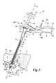
- FIG. 3is a perspective view of the instrument of FIG. 1 during insertion of a deformable prosthesis into the spine of a patient.
- FIG. 4is a partial, perspective view of the instrument of FIG. 1 with a greater portion of the prosthesis inserted into the spine as compared to FIG. 3 .
- FIG. 5is a partial, perspective view of the instrument of FIG. 1 illustrating retraction of the prosthesis.
- FIG. 1illustrates surgical implantation system 20 , which includes instrumentation 20 a .
- Instrumentation 20 aincludes implant insertion instrument 21 shown in a partial, perspective view.
- System 20also schematically depicts kit 22 including packing or container 24 and labeling 26 . Labeling 26 would typically provide instructions, warnings, and other information regarding the use of its contents.
- Instrument 21can be provided in kit 22 along with other instrumentation and materials as will be further described hereinafter.
- instrument 21extends along longitudinal axis A and has proximal end portion 28 a opposite distal end portion 28 b .
- Distal end portion 28 bis not designated in FIG. 1 because of the partial view of instrument 21 shown.
- Instrument 21includes rotational conveyor 30 that has proximal end portion 32 a opposite distal end portion 32 b .
- conveyor 30includes T-shaped handle 34 .
- Handle 34is connected to threaded conveying rod 36 .
- Rod 36includes helical threading 36 a that extends from proximal end portion 32 a to distal end portion 32 b .
- Travel stop 38is fixed to conveyor 30 proximal to rod 36 and is in the shape of a circular portion of a cone.
- Instrument 21also includes tube device 50 .
- Device 50includes tube 51 having proximal end portion 53 opposite distal end portion 58 and inner surface 52 opposite outer surface 54 .
- Inner surface 52defines passage 56 through tube 51 that extends along axis A. At least a portion of tube 51 is transparent to visualize structure therein.
- Distal end portion 58defines distal end 59 that is shaped to a point to assist with the passage of tube 51 through tissue.
- Distal end 59defines distal opening 59 a .
- Connected along distal end portion 58is flange 60 that is provided to bear against hard tissue as shown in FIGS. 3-5 .
- tube deviceincludes head 55 that has protruding members 55 a and 55 b . Members 55 a and 55 b laterally extend away from axis A.
- conveyor 30is arranged to rotate about axis A as designated by curved arrow R 1 and can move in translation relative to axis A as designated by double-headed arrow T 1 .
- accessway 57is provided in the form of an opening to passage 56 at the proximal end of head 55 .
- stop 38engages head 55 in FIG. 3 because conveyor 30 has been repositioned relative to device 50 by translational movement along axis A.
- accessway 57is closed in the view of FIG. 3 .
- further translational motion of conveyor 30 into tube 51is limited by stop 38 when it engages head 55 .
- System 20further includes deformable prosthesis 70 in the form of an elongated implant material 71 .
- Prosthesis 70can also be included in kit 22 .
- Prosthesis 70is loaded into passage 56 of instrument 21 through accessway 57 as illustrated in FIG. 1 .
- Prosthesis 70includes distal end portion 72 opposite proximal end portion 74 (see FIG. 3 .).
- Threading 36 acontacts at least a portion of prosthesis 70 , gaining purchase therewith.
- at least a portion of prosthesis 70 that is in contact with threading 36 aalso contacts tube 51 .
- material 71As material 71 is positioned in this manner, it deforms and at least partly conforms to the surfaces it contacts. Referring also to FIG. 2 , a cross-sectional view of this spatial relationship between rod 36 , tube 51 , and material 71 is shown that corresponds to section line 2 - 2 of FIG. 1 , and for which like reference numerals refer to like features.
- prosthesis 70With prosthesis 70 disposed between rod 36 and tube 51 in this manner, rotation of rod 36 about axis A tends to move prosthesis 70 along axis A, operating as a screw or worm gear conveyance device.
- prosthesis 70advances into tube 51 towards distal opening 59 a .
- stop 38can be distally advanced to engage head 55 .
- the distal end of rod 36just passes through opening 59 a of tube 51 and has its distal travel through tube 51 limited by this engagement between stop 38 and head 55 .
- scissor tool 80 of system 20 and instrumentation 20 aprovides such features.
- Tool 80detachably engages member 55 a of head 55 in a fixed relationship and stop 38 in an adjustable bearing relationship.
- Tool 80can also be included in kit 22 .
- Tool 80includes member 82 and member 84 that are pivotally coupled together by coupling 86 ; where the cross hairs designate a corresponding pivot point.
- Member 82includes distal connection 90 that attaches member 55 a to member 82 in a fixed spatial relationship and is subject to selective detachment by the user.
- Opposite distal connection 90member 82 includes proximal handle 92 with ear 98 a to facilitate proper gripping by hand.
- Member 84includes distal hold down portion 94 that is shown bearing against stop 38 corresponding to the closure of accessway 57 . Opposite distal hold down portion 94 , member 84 includes proximal handle 96 with ear 98 b to facilitate proper gripping of tool 80 by hand.
- handles 92 and 96are brought together or squeezed by hand to engage a proximal bearing surface of stop 38 with distal hold down portion 94 , which pivots about the indicated pivot point of coupling 86 .
- tool 80provides adjustable jaw mechanism 100 .
- the resulting downward pressure or force provided by mechanism 100can be modulated to permit rotation of conveyor 30 about axis A as further described hereinafter.
- Tool 80can be detached and/or portion 94 can pivot away to disengage stop 38 so that rod 36 can be pulled out of tube 51 . With the separation of stop 38 and head 55 , accessway 57 is opened.
- FIG. 4further depicts distal end portion 28 a of instrument 21 .
- material 71is deposited on a spinal structure S of patient P through opening 59 a of tube 51 by rotation of conveyor 30 in the direction indicated by arrow R 1 .
- Spinal structure Scan include, but is not limited to, vertebra V with endplate region E, and intervertebral disk space D, just to set forth some representative examples.
- Instrumentation 20 a of system 20further includes endoscope device 110 .
- Device 110is of a standard variety that includes steerable view port 112 at a distal end of optic cable 114 . The application of device 110 is further described in connection with the operation of system 20 as follows.
- system 20is utilized to perform a minimally invasive spinal implantation procedure on patient P.
- This procedureincludes forming a percutaneous passage PC through body B of patient P that extends through skin SK and subcutaneous soft tissue T as illustrated in FIG. 3 .
- a spinal disk in space Dis removed so that it can be replaced by a prosthetic device at least partially comprised of prosthesis 70 .
- Endoscope device 110can be used to visualize tissue dissection/removal via passage PC or otherwise.
- Tube device 50 of instrument 21can be used to maintain and/or define passage PC between intervertebral disk space D and the patient's skin SK, and/or a different arrangement can be utilized.
- instrument 21is assembled after discal tissue removal is completed by inserting conveyor 30 into tube 51 with distal end portion 32 b proceeding first.
- stop 38engages head 55
- advancement of conveyor 30is halted to leave accessway 57 open and to load prosthesis 70 as previously described.
- Stop 38is then moved to engage head 55 in a rotational bearing relationship.
- Tool 80is connected to member 55 a of head 55 before, during, or after loading of material 71 of prosthesis 70 .
- hold down portion 94 of tool 80is used to maintain such engagement.
- Tool 80otherwise can be used to maintain position of device 50 as conveyor 30 is rotated therein with handle 34 to advance prosthesis 70 towards distal opening 59 a of tube 51 .
- device 110can be used to visualize the deposition of material 71 of prosthesis 70 on spinal structure S with view port 112 extending through passage PC or through another percutaneous route. Advancement of material 71 is represented by arrows T 2 as rod 36 is rotated about axis A in the direction indicated by arrow R 1 .
Landscapes
- Health & Medical Sciences (AREA)
- Life Sciences & Earth Sciences (AREA)
- Biomedical Technology (AREA)
- Engineering & Computer Science (AREA)
- Orthopedic Medicine & Surgery (AREA)
- Surgery (AREA)
- Public Health (AREA)
- Oral & Maxillofacial Surgery (AREA)
- Heart & Thoracic Surgery (AREA)
- Veterinary Medicine (AREA)
- Transplantation (AREA)
- Animal Behavior & Ethology (AREA)
- General Health & Medical Sciences (AREA)
- Molecular Biology (AREA)
- Medical Informatics (AREA)
- Neurology (AREA)
- Pathology (AREA)
- Physical Education & Sports Medicine (AREA)
- Nuclear Medicine, Radiotherapy & Molecular Imaging (AREA)
- Cardiology (AREA)
- Vascular Medicine (AREA)
- Prostheses (AREA)
- Surgical Instruments (AREA)
Abstract
Description
This application is a continuation of U.S. patent application Ser. No. 11/143,404, filed Jun. 2, 2005 now abandoned, the contents of which are incorporated herein by reference in their entirety.
The present invention relates to prosthetic device implantation, and more particularly, but not exclusively, relates to techniques to insert a deformable spinal prosthesis and related instrumentation.
The use of prosthetic implants to address orthopedic injuries and ailments has become commonplace. Nonetheless, there is an ever-present challenge to enable less invasive surgical techniques, shorten the time required to surgically implant prosthetic devices, decrease surgery recovery time, and/or provide other improvements. Thus, there is a need for additional contributions in this area of technology.
One embodiment of the present application is a unique technique to implant a deformable prosthetic device. Other embodiments include unique methods, systems, devices, kits, tools, instrumentation, and apparatus involving implantation of a deformable prosthetic device.
A further embodiment includes operating an instrument that percutaneously extends into a patient's body, the instrument including a tube, a threaded conveying rod extending inside the tube, a proximal end portion, and a distal end portion. The instrument is placed into position with the distal end portion in proximity to a spinal structure of the patient's body while the proximal end portion remains outside the patient's body. With a deformable prosthesis being positioned between the tube and the rod, it is moved through the tube by rotating the rod while in position. At least a portion of the prosthesis is deposited on the spinal structure with the instrument.
Various forms of this embodiment optionally include: reversing direction of rotation to change direction of deformable prosthesis movement through the tube, and/or turning a handle coupled to the rod to cause rod rotation. Alternatively or additionally this embodiment can optionally include: attaching a tool to the tube, maintaining location of the tube relative to the rod with the tool, and holding down the rod by engaging a travel stop fixed to the rod with a member connected to the tool.
Another embodiment is directed to a kit or system to perform a spinal implantation procedure. In one form, this kit includes: a tube device with an inner surface defining a passage from a proximal end portion to a distal end portion, a conveyor including a threaded conveying rod to be received in the passage of the tube device that can be rotated in the tube or moved in translation along the passage, and a deformable prosthesis structured to move through the passage of the tube by rotating the threaded conveying rod while at least a portion of the deformable prosthesis is positioned between the inner surface and the rod.
Still another embodiment includes instrumentation that comprises: a threaded conveying rod structured to rotate about an axis of rotation, a tube device including a tube extending along the axis of rotation and defining a passage therethrough to receive the rod, a handle coupled to a proximal end portion of the threaded conveying rod, and a travel stop structured to engage the tube device to limit at least one translational direction of travel of the rod along the axis. The rod is structured to rotate in response to rotation of the handle and to move in translation in response to movement of the handle along the axis of rotation and the tube is sized and shaped to have a distal end portion placed inside a body of a patient while a proximal end portion remains outside the body of the patient. The tube includes an accessway to the passage to receive a deformable prosthesis that can be inserted in the patient's body with the instrumentation.
One object of the present application is to provide a unique implantation technique.
Alternatively or additionally, another object of the present application is to provide a unique method, system, device, kit, tool, instrument, and/or apparatus involving implantation of a deformable prosthetic device.
Further embodiments, forms, features, aspects, benefits, objects, and advantages of the present application shall become apparent from the detailed description and figures provided herewith.
For the purpose of promoting an understanding of the principles of the invention, reference will now be made to the embodiments illustrated in the drawings and specific language will be used to describe the same. It will nevertheless be understood that no limitation of the scope of the invention is thereby intended. Any alterations or further modifications of the described embodiments, and any further applications of the principles of the invention as described herein are contemplated as would normally occur to one skilled in the art to which the invention relates.
Referring additionally toFIGS. 3-5 ,instrument 21 extends along longitudinal axis A and hasproximal end portion 28aoppositedistal end portion 28b.Distal end portion 28bis not designated inFIG. 1 because of the partial view ofinstrument 21 shown.Instrument 21 includesrotational conveyor 30 that hasproximal end portion 32aoppositedistal end portion 32b. Alongproximal end portion 32a,conveyor 30 includes T-shaped handle 34.Handle 34 is connected to threadedconveying rod 36.Rod 36 includeshelical threading 36athat extends fromproximal end portion 32atodistal end portion 32b.Travel stop 38 is fixed toconveyor 30 proximal torod 36 and is in the shape of a circular portion of a cone.
Referring specifically toFIGS. 1 and 3 ,conveyor 30 is arranged to rotate about axis A as designated by curved arrow R1 and can move in translation relative to axis A as designated by double-headed arrow T1. For the position ofconveyor 30 relative todevice 50 shown inFIG. 1 ,accessway 57 is provided in the form of an opening topassage 56 at the proximal end ofhead 55. In comparison,stop 38 engageshead 55 inFIG. 3 becauseconveyor 30 has been repositioned relative todevice 50 by translational movement along axis A. As a result,accessway 57 is closed in the view ofFIG. 3 . Correspondingly, further translational motion ofconveyor 30 intotube 51 is limited bystop 38 when it engageshead 55.
Withprosthesis 70 disposed betweenrod 36 andtube 51 in this manner, rotation ofrod 36 about axis A tends to moveprosthesis 70 along axis A, operating as a screw or worm gear conveyance device. For rotation ofrod 36 in the direction indicated by arrow R1,prosthesis 70 advances intotube 51 towards distal opening59a. After prosthesis70 is loaded intotube 51 and/or if there is a continuously open accessway for prosthesis (not shown), stop38 can be distally advanced to engagehead 55. For such placement, the distal end ofrod 36 just passes through opening59aoftube 51 and has its distal travel throughtube 51 limited by this engagement betweenstop 38 andhead 55. For this configuration, rotation ofrod 36 about axis A can continue, providing further distal advancement ofprosthesis 70 throughtube 51 and out opening59a. In some applications, it is desirable to maintaindevice 50 in a desired position asrod 36 rotates and/or to holdstop 38 in a rotational bearing relationship withhead 55.
As shown inFIG. 3 ,scissor tool 80 ofsystem 20 andinstrumentation 20aprovides such features.Tool 80 detachably engagesmember 55aofhead 55 in a fixed relationship and stop38 in an adjustable bearing relationship.Tool 80 can also be included inkit 22.Tool 80 includesmember 82 andmember 84 that are pivotally coupled together by coupling86; where the cross hairs designate a corresponding pivot point.Member 82 includesdistal connection 90 that attachesmember 55atomember 82 in a fixed spatial relationship and is subject to selective detachment by the user. Oppositedistal connection 90,member 82 includesproximal handle 92 withear 98ato facilitate proper gripping by hand.Member 84 includes distal hold downportion 94 that is shown bearing againststop 38 corresponding to the closure ofaccessway 57. Opposite distal hold downportion 94,member 84 includesproximal handle 96 withear 98bto facilitate proper gripping oftool 80 by hand.
Afterdistal connection 90 oftool 80 is formed, handles92 and96 are brought together or squeezed by hand to engage a proximal bearing surface ofstop 38 with distal hold downportion 94, which pivots about the indicated pivot point ofcoupling 86. Correspondingly,tool 80 providesadjustable jaw mechanism 100. The resulting downward pressure or force provided bymechanism 100 can be modulated to permit rotation ofconveyor 30 about axis A as further described hereinafter.Tool 80 can be detached and/orportion 94 can pivot away to disengagestop 38 so thatrod 36 can be pulled out oftube 51. With the separation ofstop 38 andhead 55,accessway 57 is opened.
Referring generally toFIGS. 1-5 , one mode ofoperating system 20 is next described. In this application,system 20 is utilized to perform a minimally invasive spinal implantation procedure on patient P. This procedure includes forming a percutaneous passage PC through body B of patient P that extends through skin SK and subcutaneous soft tissue T as illustrated inFIG. 3 . For this example, at least a portion of a spinal disk in space D is removed so that it can be replaced by a prosthetic device at least partially comprised ofprosthesis 70. Such removal can occur through passage PC and/or one or more other passages in body B of patientP. Endoscope device 110 can be used to visualize tissue dissection/removal via passage PC or otherwise.Tube device 50 ofinstrument 21 can be used to maintain and/or define passage PC between intervertebral disk space D and the patient's skin SK, and/or a different arrangement can be utilized.
Withtube device 50 positioned through passage PC,instrument 21 is assembled after discal tissue removal is completed by insertingconveyor 30 intotube 51 withdistal end portion 32bproceeding first. Beforestop 38 engageshead 55, advancement ofconveyor 30 is halted to leaveaccessway 57 open and to loadprosthesis 70 as previously described.Stop 38 is then moved to engagehead 55 in a rotational bearing relationship.Tool 80 is connected tomember 55aofhead 55 before, during, or after loading ofmaterial 71 ofprosthesis 70. Afterhead 55 is engaged bystop 38, hold downportion 94 oftool 80 is used to maintain such engagement.Tool 80 otherwise can be used to maintain position ofdevice 50 asconveyor 30 is rotated therein withhandle 34 to advanceprosthesis 70 towards distal opening59aoftube 51.
With specific reference toFIG. 4 ,device 110 can be used to visualize the deposition ofmaterial 71 ofprosthesis 70 on spinal structure S with view port112 extending through passage PC or through another percutaneous route. Advancement ofmaterial 71 is represented by arrows T2 asrod 36 is rotated about axis A in the direction indicated by arrow R1.
During the procedure, the need to remove or retract some or all ofmaterial 71 can arise. By reversing rotational direction of conveyor to turn in the opposite rotational direction as represented by arrow R2 inFIG. 5 ,material 71 can be retracted from space D and back intotube 51 as represented by arrow T3. Onceprosthesis 70 is fully retracted intotube 51, hold downportion 94 oftool 80 can be released andconveyor 30 can be proximally withdrawn fromdevice 50 to correspondingly withdrawprosthesis 70. Adjustments can be performed to continue the procedure as needed. Onceprosthesis 70 is in position relative to the spine of patient P, suturing of it can take place or it is otherwise secured as needed using standard techniques.
While the invention has been illustrated and described in detail in the drawings and foregoing description, the same is to be considered illustrative and not restrictive in character, it being understood that only selected embodiments have been shown and described and that all changes, equivalents, and modifications that come within the scope of the inventions described herein or defined by the following claims are desired to be protected. Any experiments, experimental examples, or experimental results provided herein are intended to be illustrative of the present invention and should not be construed to limit or restrict the invention scope. Further, any theory, mechanism of operation, proof, or finding stated herein is meant to further enhance understanding of the present invention and is not intended to limit the present invention in any way to such theory, mechanism of operation, proof, or finding. In reading the claims, words such as “a”, “an”, “at least on”, and “at least a portion” are not intended to limit the claims to only one item unless specifically stated to the contrary. Further, when the language “at least a portion” and/or “a portion” is used, the claims may include a portion and/or the entire item unless specifically stated to the contrary.
Claims (10)
1. A method, comprising:
operating an instrument that percutaneously extends into a patient's body, the instrument including a tube, a threaded conveying rod extending inside the tube, a proximal end portion and a distal end portion;
placing the instrument into a position with the distal end portion in proximity to a spinal structure of the patient's body while the proximal end portion remains outside the patient's body;
with a deformable prosthesis including an elongate implant material extending along a longitudinal axis between a distal end and an opposite proximal end, the elongate implant material being positioned between an inner surface of the tube and threading on the rod in purchase with the elongate implant material of the prosthesis so that the longitudinal axis of the implant material is offset from a longitudinal axis of the rod, moving the deformable prosthesis through the tube by rotating the rod while in the position; and
depositing at least a portion of the elongate implant material of the prosthesis on the spinal structure with the instrument.
2. The method ofclaim 1 , which includes reversing direction of said rotating to change direction of the moving of the deformable prosthesis through the tube so that the elongate implant material retracts from the spinal structure.
3. The method ofclaim 1 , which includes turning a handle coupled to the rod to perform said rotating.
4. The method ofclaim 1 , which includes:
attaching a tool to the tube;
maintaining location of the tube relative to rod during said rotating; and
holding down the rod by engaging a travel stop fixed to the rod in rotating bearing relationship with a member connected to the tool.
5. The method ofclaim 1 , which includes:
forming a percutaneous passageway through the patient's body;
inserting the instrument through the passageway; and
visualizing said operating of the instrument with an endoscope device.
6. The method ofclaim 1 , which includes passing the deformable prosthesis through an accessway to the passage in the tube.
7. The method ofclaim 6 , which includes:
closing the accessway by moving the rod in translation along an axis in a first direction; and
opening the accessway by moving the rod in translation along the axis in a second direction opposite the first direction.
8. The method ofclaim 1 , wherein the rod and elongate implant material are positioned eccentrically in the tube.
9. The method ofclaim 1 , wherein the elongate implant material is continuous between its proximal and distal ends.
10. The method ofclaim 1 , wherein moving the deformable prosthesis through the tube by rotating the rod while in the position includes advancing the distal end of the elongate material through the tube while advancing the proximal end of the elongate material from a location outside the tube into the tube by rotating the rod.
Priority Applications (1)
| Application Number | Priority Date | Filing Date | Title |
|---|---|---|---|
| US11/343,230US7828807B2 (en) | 2005-04-29 | 2006-01-30 | Implantation of a deformable prosthesic device |
Applications Claiming Priority (4)
| Application Number | Priority Date | Filing Date | Title |
|---|---|---|---|
| FR0504428AFR2885032B1 (en) | 2005-04-29 | 2005-04-29 | KIT AND INSTRUMENTATION FOR EXECUTING A SPINAL IMPLANTATION PROCEDURE |
| FR0504428 | 2005-04-29 | ||
| US14340405A | 2005-06-02 | 2005-06-02 | |
| US11/343,230US7828807B2 (en) | 2005-04-29 | 2006-01-30 | Implantation of a deformable prosthesic device |
Related Parent Applications (1)
| Application Number | Title | Priority Date | Filing Date |
|---|---|---|---|
| US14340405AContinuation | 2005-04-29 | 2005-06-02 |
Publications (2)
| Publication Number | Publication Date |
|---|---|
| US20070005088A1 US20070005088A1 (en) | 2007-01-04 |
| US7828807B2true US7828807B2 (en) | 2010-11-09 |
Family
ID=35544640
Family Applications (1)
| Application Number | Title | Priority Date | Filing Date |
|---|---|---|---|
| US11/343,230Active2028-02-19US7828807B2 (en) | 2005-04-29 | 2006-01-30 | Implantation of a deformable prosthesic device |
Country Status (2)
| Country | Link |
|---|---|
| US (1) | US7828807B2 (en) |
| FR (1) | FR2885032B1 (en) |
Cited By (50)
| Publication number | Priority date | Publication date | Assignee | Title |
|---|---|---|---|---|
| US20070100510A1 (en)* | 2005-10-25 | 2007-05-03 | Denso Corporation | Method and system for application control |
| US20080234687A1 (en)* | 2005-08-16 | 2008-09-25 | Laurent Schaller | Devices for treating the spine |
| US20090318975A1 (en)* | 2005-05-23 | 2009-12-24 | Custom Spine, Inc. | Rod Reducer Method |
| US20100114107A1 (en)* | 2000-08-30 | 2010-05-06 | Warsaw Orthopedic, Inc. | Intervertebral Disc Nucleus Implants and Methods |
| US8366773B2 (en) | 2005-08-16 | 2013-02-05 | Benvenue Medical, Inc. | Apparatus and method for treating bone |
| US8556978B2 (en) | 2005-08-16 | 2013-10-15 | Benvenue Medical, Inc. | Devices and methods for treating the vertebral body |
| US8591583B2 (en) | 2005-08-16 | 2013-11-26 | Benvenue Medical, Inc. | Devices for treating the spine |
| US8814873B2 (en) | 2011-06-24 | 2014-08-26 | Benvenue Medical, Inc. | Devices and methods for treating bone tissue |
| US9044334B2 (en) | 2010-07-21 | 2015-06-02 | Nlt Spine Ltd. | Spinal surgery implants and delivery system |
| US9433404B2 (en) | 2012-10-31 | 2016-09-06 | Suture Concepts Inc. | Method and apparatus for closing fissures in the annulus fibrosus |
| US9788963B2 (en) | 2003-02-14 | 2017-10-17 | DePuy Synthes Products, Inc. | In-situ formed intervertebral fusion device and method |
| US9867714B1 (en) | 2011-09-23 | 2018-01-16 | Samy Abdou | Spinal fixation devices and methods of use |
| US9949734B2 (en) | 2012-10-31 | 2018-04-24 | Suture Concepts Inc. | Method and apparatus for closing a fissure in the annulus of an intervertebral disc, and/or for effecting other anatomical repairs and/or fixations |
| US10085783B2 (en) | 2013-03-14 | 2018-10-02 | Izi Medical Products, Llc | Devices and methods for treating bone tissue |
| US10111757B2 (en) | 2012-10-22 | 2018-10-30 | Cogent Spine, LLC | Devices and methods for spinal stabilization and instrumentation |
| US10231846B2 (en) | 2016-08-19 | 2019-03-19 | Stryker European Holdings I, Llc | Bone graft delivery loading assembly |
| US10543107B2 (en) | 2009-12-07 | 2020-01-28 | Samy Abdou | Devices and methods for minimally invasive spinal stabilization and instrumentation |
| US10548740B1 (en) | 2016-10-25 | 2020-02-04 | Samy Abdou | Devices and methods for vertebral bone realignment |
| US10695105B2 (en) | 2012-08-28 | 2020-06-30 | Samy Abdou | Spinal fixation devices and methods of use |
| US10786235B2 (en) | 2012-10-31 | 2020-09-29 | Anchor Innovation Medical, Inc. | Method and apparatus for closing a fissure in the annulus of an intervertebral disc, and/or for effecting other anatomical repairs and/or fixations |
| US10857003B1 (en) | 2015-10-14 | 2020-12-08 | Samy Abdou | Devices and methods for vertebral stabilization |
| US10888433B2 (en) | 2016-12-14 | 2021-01-12 | DePuy Synthes Products, Inc. | Intervertebral implant inserter and related methods |
| US10918498B2 (en) | 2004-11-24 | 2021-02-16 | Samy Abdou | Devices and methods for inter-vertebral orthopedic device placement |
| US10940016B2 (en) | 2017-07-05 | 2021-03-09 | Medos International Sarl | Expandable intervertebral fusion cage |
| US10966840B2 (en) | 2010-06-24 | 2021-04-06 | DePuy Synthes Products, Inc. | Enhanced cage insertion assembly |
| US10973648B1 (en) | 2016-10-25 | 2021-04-13 | Samy Abdou | Devices and methods for vertebral bone realignment |
| US10973652B2 (en) | 2007-06-26 | 2021-04-13 | DePuy Synthes Products, Inc. | Highly lordosed fusion cage |
| US11006982B2 (en) | 2012-02-22 | 2021-05-18 | Samy Abdou | Spinous process fixation devices and methods of use |
| US11179248B2 (en) | 2018-10-02 | 2021-11-23 | Samy Abdou | Devices and methods for spinal implantation |
| US11273050B2 (en) | 2006-12-07 | 2022-03-15 | DePuy Synthes Products, Inc. | Intervertebral implant |
| US11344424B2 (en) | 2017-06-14 | 2022-05-31 | Medos International Sarl | Expandable intervertebral implant and related methods |
| US11426286B2 (en) | 2020-03-06 | 2022-08-30 | Eit Emerging Implant Technologies Gmbh | Expandable intervertebral implant |
| US11426290B2 (en) | 2015-03-06 | 2022-08-30 | DePuy Synthes Products, Inc. | Expandable intervertebral implant, system, kit and method |
| US11446156B2 (en) | 2018-10-25 | 2022-09-20 | Medos International Sarl | Expandable intervertebral implant, inserter instrument, and related methods |
| US11446155B2 (en) | 2017-05-08 | 2022-09-20 | Medos International Sarl | Expandable cage |
| US11452607B2 (en) | 2010-10-11 | 2022-09-27 | DePuy Synthes Products, Inc. | Expandable interspinous process spacer implant |
| US11497619B2 (en) | 2013-03-07 | 2022-11-15 | DePuy Synthes Products, Inc. | Intervertebral implant |
| US11510788B2 (en) | 2016-06-28 | 2022-11-29 | Eit Emerging Implant Technologies Gmbh | Expandable, angularly adjustable intervertebral cages |
| US11596523B2 (en) | 2016-06-28 | 2023-03-07 | Eit Emerging Implant Technologies Gmbh | Expandable and angularly adjustable articulating intervertebral cages |
| US11602438B2 (en) | 2008-04-05 | 2023-03-14 | DePuy Synthes Products, Inc. | Expandable intervertebral implant |
| US11607321B2 (en) | 2009-12-10 | 2023-03-21 | DePuy Synthes Products, Inc. | Bellows-like expandable interbody fusion cage |
| US11612491B2 (en) | 2009-03-30 | 2023-03-28 | DePuy Synthes Products, Inc. | Zero profile spinal fusion cage |
| US11654033B2 (en) | 2010-06-29 | 2023-05-23 | DePuy Synthes Products, Inc. | Distractible intervertebral implant |
| US11737881B2 (en) | 2008-01-17 | 2023-08-29 | DePuy Synthes Products, Inc. | Expandable intervertebral implant and associated method of manufacturing the same |
| US11752009B2 (en) | 2021-04-06 | 2023-09-12 | Medos International Sarl | Expandable intervertebral fusion cage |
| US11850160B2 (en) | 2021-03-26 | 2023-12-26 | Medos International Sarl | Expandable lordotic intervertebral fusion cage |
| US11911287B2 (en) | 2010-06-24 | 2024-02-27 | DePuy Synthes Products, Inc. | Lateral spondylolisthesis reduction cage |
| USRE49973E1 (en) | 2013-02-28 | 2024-05-21 | DePuy Synthes Products, Inc. | Expandable intervertebral implant, system, kit and method |
| US12090064B2 (en) | 2022-03-01 | 2024-09-17 | Medos International Sarl | Stabilization members for expandable intervertebral implants, and related systems and methods |
| US12440346B2 (en) | 2023-03-31 | 2025-10-14 | DePuy Synthes Products, Inc. | Expandable intervertebral implant |
Families Citing this family (9)
| Publication number | Priority date | Publication date | Assignee | Title |
|---|---|---|---|---|
| DE602004019917D1 (en)* | 2003-06-02 | 2009-04-23 | Warsaw Orthopedic Inc | BAND DISC IMPLANTS AND METHODS FOR THE PRODUCTION THEREOF |
| WO2009111480A2 (en)* | 2008-03-03 | 2009-09-11 | Trinity Orthopedics, Llc | Spool intervertebral distraction device and method |
| FR2929502B1 (en) | 2008-04-04 | 2011-04-08 | Clariance | NUCLEIC IMPLANT. |
| CN104887170B (en) | 2008-09-05 | 2017-06-09 | 卡内基梅隆大学 | More piece endoscopic apparatus with spherical distal ends component |
| US8512408B2 (en) | 2010-12-17 | 2013-08-20 | Warsaw Orthopedic, Inc. | Flexiable spinal implant |
| MY162928A (en)* | 2011-03-23 | 2017-07-31 | E Yeung Jeffrey | Tissue repair with space-seeking spirals of filament |
| US11464648B2 (en)* | 2019-09-09 | 2022-10-11 | Amplify Surgical, Inc. | Multi-portal surgical systems |
| US11678906B2 (en) | 2019-09-09 | 2023-06-20 | Amplify Surgical, Inc. | Multi-portal surgical systems, cannulas, and related technologies |
| US11950770B1 (en) | 2022-12-01 | 2024-04-09 | Amplify Surgical, Inc. | Multi-portal split cannulas, endoscopic hemostatic dispensers and surgical tools |
Citations (40)
| Publication number | Priority date | Publication date | Assignee | Title |
|---|---|---|---|---|
| US1077810A (en)* | 1911-06-29 | 1913-11-04 | Richard Harvey Wright | Apparatus for filling and packing materials into receptacles. |
| USRE24079E (en)* | 1955-10-25 | Screw actuated hopper feeder | ||
| US3081644A (en)* | 1959-10-05 | 1963-03-19 | Gemmer Mfg Co | Close tolerance anti-friction component assembly |
| US3743140A (en)* | 1970-12-21 | 1973-07-03 | Diehl Mateer G Co | Filler apparatus with hopper and rotary feed mechanism for dispensing controlled volumes of materials |
| US4582097A (en)* | 1983-10-05 | 1986-04-15 | Mateer-Burt Company, Inc. | Control apparatus and method for automatic filling machine |
| US4636217A (en) | 1985-04-23 | 1987-01-13 | Regents Of The University Of Minnesota | Anterior spinal implant |
| US4648285A (en)* | 1983-02-14 | 1987-03-10 | Millipore Corporation | Apparatus for converting rotational motion to linear motion |
| US4811618A (en)* | 1986-12-12 | 1989-03-14 | Nippon Gear Co., Ltd. | Motion conversion mechanism |
| US4881862A (en)* | 1987-09-30 | 1989-11-21 | Jenike & Johanson, Inc. | Screw seal |
| US4964314A (en)* | 1989-03-13 | 1990-10-23 | Wilkes Donald F | Device for converting rotary motion to linear motion |
| US4973334A (en) | 1987-01-16 | 1990-11-27 | Allo Pro Ag | Device for ejecting or taking in liquid or paste-like media |
| US5071040A (en)* | 1990-03-09 | 1991-12-10 | Pfizer Hospital Products Group, Inc. | Surgical adhesives mixing and dispensing implement |
| US5171280A (en) | 1990-04-20 | 1992-12-15 | Sulzer Brothers Limited | Intervertebral prosthesis |
| US5263927A (en)* | 1992-09-02 | 1993-11-23 | Shlain Leonard M | Apparatus and methods for dispensing surgical packing |
| US5577850A (en)* | 1992-07-31 | 1996-11-26 | Pentel Kabushiki Kaisha | Rodlike body feeding device |
| US5645597A (en) | 1995-12-29 | 1997-07-08 | Krapiva; Pavel I. | Disc replacement method and apparatus |
| US5716416A (en) | 1996-09-10 | 1998-02-10 | Lin; Chih-I | Artificial intervertebral disk and method for implanting the same |
| US5919235A (en) | 1995-11-08 | 1999-07-06 | Sulzer Orthopaedie Ag | Intervertebral prosthesis |
| US6019765A (en) | 1998-05-06 | 2000-02-01 | Johnson & Johnson Professional, Inc. | Morsellized bone allograft applicator device |
| US6062438A (en)* | 1998-04-20 | 2000-05-16 | Mars, Inc. | Apparatus for dispensing of bulk product |
| US6090063A (en)* | 1995-12-01 | 2000-07-18 | C. R. Bard, Inc. | Device, system and method for implantation of filaments and particles in the body |
| US6245107B1 (en) | 1999-05-28 | 2001-06-12 | Bret A. Ferree | Methods and apparatus for treating disc herniation |
| US6264659B1 (en) | 1999-02-22 | 2001-07-24 | Anthony C. Ross | Method of treating an intervertebral disk |
| US6267763B1 (en) | 1999-03-31 | 2001-07-31 | Surgical Dynamics, Inc. | Method and apparatus for spinal implant insertion |
| US6280475B1 (en) | 1994-09-08 | 2001-08-28 | Stryker Technologies Corporation | Hydrogel intervertebral disc nucleus implantation method |
| US20020082605A1 (en) | 1997-08-13 | 2002-06-27 | Kyphon Inc. | Systems and methods for injecting flowable materials into bones |
| US20020188295A1 (en) | 2000-11-07 | 2002-12-12 | Erik Martz | Spinal intervertebral implant insertion tool |
| US6547465B1 (en)* | 2002-01-22 | 2003-04-15 | Shoot The Moon Products Ii, Llc | Pencil with exposable eraser |
| US6579291B1 (en) | 2000-10-10 | 2003-06-17 | Spinalabs, Llc | Devices and methods for the treatment of spinal disorders |
| US20030149438A1 (en) | 2001-04-30 | 2003-08-07 | Howmedica Osteonics Corp. | Insertion instrument |
| US6620196B1 (en) | 2000-08-30 | 2003-09-16 | Sdgi Holdings, Inc. | Intervertebral disc nucleus implants and methods |
| US20030216737A1 (en) | 2002-05-15 | 2003-11-20 | Spineco Inc., A Corporation Of Ohio | Spinal implant insertion tool |
| US6660006B2 (en) | 2002-04-17 | 2003-12-09 | Stryker Spine | Rod persuader |
| US20040024409A1 (en) | 1997-08-13 | 2004-02-05 | Kyphon Inc. | Systems and methods for injecting flowable materials into bones |
| US20040024463A1 (en) | 2001-08-27 | 2004-02-05 | Thomas James C. | Expandable implant for partial disc replacement and reinforcement of a disc partially removed in a discectomy and for reduction and maintenance of alignment of cancellous bone fractures and methods and apparatuses for same |
| US6689125B1 (en) | 2000-04-04 | 2004-02-10 | Spinalabs, Llc | Devices and methods for the treatment of spinal disorders |
| US7008433B2 (en)* | 2001-02-15 | 2006-03-07 | Depuy Acromed, Inc. | Vertebroplasty injection device |
| US7014640B2 (en)* | 2003-03-28 | 2006-03-21 | Depuy Products, Inc. | Bone graft delivery device and method of use |
| US20080051800A1 (en)* | 2004-05-03 | 2008-02-28 | Robert Diaz | Method and device for reducing susceptibility to fractures in vertebral bodies |
| US20100044656A1 (en)* | 2008-02-25 | 2010-02-25 | Kenji Imase | Worm-rack type transmission device |
Family Cites Families (7)
| Publication number | Priority date | Publication date | Assignee | Title |
|---|---|---|---|---|
| ES283078Y (en)* | 1984-11-30 | 1985-12-16 | Otero Vich Jose M. | BONE INSERT FOR CERVICAL INTERSOMATIC ARTHRODESIS |
| FR2712486A1 (en)* | 1993-11-19 | 1995-05-24 | Breslave Patrice | Intervertebral prosthesis |
| US5431658A (en)* | 1994-02-14 | 1995-07-11 | Moskovich; Ronald | Facilitator for vertebrae grafts and prostheses |
| US5653762A (en)* | 1994-03-18 | 1997-08-05 | Pisharodi; Madhavan | Method of stabilizing adjacent vertebrae with rotating, lockable, middle-expanded intervertebral disk stabilizer |
| DE19750382A1 (en)* | 1997-11-13 | 1999-05-20 | Augustin Prof Dr Med Betz | Operative correction equipment for displaced vertebrae used in minimally invasive surgery |
| NL1012719C1 (en)* | 1999-07-28 | 2001-01-30 | Veldhuizen Dr Ag | Spine prosthesis. |
| US20020026244A1 (en)* | 2000-08-30 | 2002-02-28 | Trieu Hai H. | Intervertebral disc nucleus implants and methods |
- 2005
- 2005-04-29FRFR0504428Apatent/FR2885032B1/ennot_activeExpired - Fee Related
- 2006
- 2006-01-30USUS11/343,230patent/US7828807B2/enactiveActive
Patent Citations (44)
| Publication number | Priority date | Publication date | Assignee | Title |
|---|---|---|---|---|
| USRE24079E (en)* | 1955-10-25 | Screw actuated hopper feeder | ||
| US1077810A (en)* | 1911-06-29 | 1913-11-04 | Richard Harvey Wright | Apparatus for filling and packing materials into receptacles. |
| US3081644A (en)* | 1959-10-05 | 1963-03-19 | Gemmer Mfg Co | Close tolerance anti-friction component assembly |
| US3743140A (en)* | 1970-12-21 | 1973-07-03 | Diehl Mateer G Co | Filler apparatus with hopper and rotary feed mechanism for dispensing controlled volumes of materials |
| US4648285A (en)* | 1983-02-14 | 1987-03-10 | Millipore Corporation | Apparatus for converting rotational motion to linear motion |
| US4582097A (en)* | 1983-10-05 | 1986-04-15 | Mateer-Burt Company, Inc. | Control apparatus and method for automatic filling machine |
| US4636217A (en) | 1985-04-23 | 1987-01-13 | Regents Of The University Of Minnesota | Anterior spinal implant |
| US4811618A (en)* | 1986-12-12 | 1989-03-14 | Nippon Gear Co., Ltd. | Motion conversion mechanism |
| US4973334A (en) | 1987-01-16 | 1990-11-27 | Allo Pro Ag | Device for ejecting or taking in liquid or paste-like media |
| US4881862A (en)* | 1987-09-30 | 1989-11-21 | Jenike & Johanson, Inc. | Screw seal |
| US4964314A (en)* | 1989-03-13 | 1990-10-23 | Wilkes Donald F | Device for converting rotary motion to linear motion |
| US5071040A (en)* | 1990-03-09 | 1991-12-10 | Pfizer Hospital Products Group, Inc. | Surgical adhesives mixing and dispensing implement |
| US5171280A (en) | 1990-04-20 | 1992-12-15 | Sulzer Brothers Limited | Intervertebral prosthesis |
| US5577850A (en)* | 1992-07-31 | 1996-11-26 | Pentel Kabushiki Kaisha | Rodlike body feeding device |
| US5263927A (en)* | 1992-09-02 | 1993-11-23 | Shlain Leonard M | Apparatus and methods for dispensing surgical packing |
| US6280475B1 (en) | 1994-09-08 | 2001-08-28 | Stryker Technologies Corporation | Hydrogel intervertebral disc nucleus implantation method |
| US6610094B2 (en) | 1995-11-08 | 2003-08-26 | Sulzer Orthopaedie Ag | Intervertebral prosthesis |
| US6660037B1 (en) | 1995-11-08 | 2003-12-09 | Sulzer Orthopaedie Ag | Intervertebral prosthesis |
| US5919235A (en) | 1995-11-08 | 1999-07-06 | Sulzer Orthopaedie Ag | Intervertebral prosthesis |
| US6165218A (en) | 1995-11-08 | 2000-12-26 | Sulzer Orthopaedie Ag | Intervertebral prosthesis |
| US6090063A (en)* | 1995-12-01 | 2000-07-18 | C. R. Bard, Inc. | Device, system and method for implantation of filaments and particles in the body |
| US5645597A (en) | 1995-12-29 | 1997-07-08 | Krapiva; Pavel I. | Disc replacement method and apparatus |
| US5716416A (en) | 1996-09-10 | 1998-02-10 | Lin; Chih-I | Artificial intervertebral disk and method for implanting the same |
| US20020082605A1 (en) | 1997-08-13 | 2002-06-27 | Kyphon Inc. | Systems and methods for injecting flowable materials into bones |
| US20040024409A1 (en) | 1997-08-13 | 2004-02-05 | Kyphon Inc. | Systems and methods for injecting flowable materials into bones |
| US6062438A (en)* | 1998-04-20 | 2000-05-16 | Mars, Inc. | Apparatus for dispensing of bulk product |
| US6019765A (en) | 1998-05-06 | 2000-02-01 | Johnson & Johnson Professional, Inc. | Morsellized bone allograft applicator device |
| US6264659B1 (en) | 1999-02-22 | 2001-07-24 | Anthony C. Ross | Method of treating an intervertebral disk |
| US6267763B1 (en) | 1999-03-31 | 2001-07-31 | Surgical Dynamics, Inc. | Method and apparatus for spinal implant insertion |
| US6245107B1 (en) | 1999-05-28 | 2001-06-12 | Bret A. Ferree | Methods and apparatus for treating disc herniation |
| US6689125B1 (en) | 2000-04-04 | 2004-02-10 | Spinalabs, Llc | Devices and methods for the treatment of spinal disorders |
| US6620196B1 (en) | 2000-08-30 | 2003-09-16 | Sdgi Holdings, Inc. | Intervertebral disc nucleus implants and methods |
| US6579291B1 (en) | 2000-10-10 | 2003-06-17 | Spinalabs, Llc | Devices and methods for the treatment of spinal disorders |
| US6666866B2 (en) | 2000-11-07 | 2003-12-23 | Osteotech, Inc. | Spinal intervertebral implant insertion tool |
| US20020188295A1 (en) | 2000-11-07 | 2002-12-12 | Erik Martz | Spinal intervertebral implant insertion tool |
| US7008433B2 (en)* | 2001-02-15 | 2006-03-07 | Depuy Acromed, Inc. | Vertebroplasty injection device |
| US20030149438A1 (en) | 2001-04-30 | 2003-08-07 | Howmedica Osteonics Corp. | Insertion instrument |
| US20040024463A1 (en) | 2001-08-27 | 2004-02-05 | Thomas James C. | Expandable implant for partial disc replacement and reinforcement of a disc partially removed in a discectomy and for reduction and maintenance of alignment of cancellous bone fractures and methods and apparatuses for same |
| US6547465B1 (en)* | 2002-01-22 | 2003-04-15 | Shoot The Moon Products Ii, Llc | Pencil with exposable eraser |
| US6660006B2 (en) | 2002-04-17 | 2003-12-09 | Stryker Spine | Rod persuader |
| US20030216737A1 (en) | 2002-05-15 | 2003-11-20 | Spineco Inc., A Corporation Of Ohio | Spinal implant insertion tool |
| US7014640B2 (en)* | 2003-03-28 | 2006-03-21 | Depuy Products, Inc. | Bone graft delivery device and method of use |
| US20080051800A1 (en)* | 2004-05-03 | 2008-02-28 | Robert Diaz | Method and device for reducing susceptibility to fractures in vertebral bodies |
| US20100044656A1 (en)* | 2008-02-25 | 2010-02-25 | Kenji Imase | Worm-rack type transmission device |
Cited By (135)
| Publication number | Priority date | Publication date | Assignee | Title |
|---|---|---|---|---|
| US20100114107A1 (en)* | 2000-08-30 | 2010-05-06 | Warsaw Orthopedic, Inc. | Intervertebral Disc Nucleus Implants and Methods |
| US10420651B2 (en) | 2003-02-14 | 2019-09-24 | DePuy Synthes Products, Inc. | In-situ formed intervertebral fusion device and method |
| US9814590B2 (en) | 2003-02-14 | 2017-11-14 | DePuy Synthes Products, Inc. | In-situ formed intervertebral fusion device and method |
| US9801729B2 (en) | 2003-02-14 | 2017-10-31 | DePuy Synthes Products, Inc. | In-situ formed intervertebral fusion device and method |
| US10639164B2 (en) | 2003-02-14 | 2020-05-05 | DePuy Synthes Products, Inc. | In-situ formed intervertebral fusion device and method |
| US11096794B2 (en) | 2003-02-14 | 2021-08-24 | DePuy Synthes Products, Inc. | In-situ formed intervertebral fusion device and method |
| US10583013B2 (en) | 2003-02-14 | 2020-03-10 | DePuy Synthes Products, Inc. | In-situ formed intervertebral fusion device and method |
| US10575959B2 (en) | 2003-02-14 | 2020-03-03 | DePuy Synthes Products, Inc. | In-situ formed intervertebral fusion device and method |
| US9814589B2 (en) | 2003-02-14 | 2017-11-14 | DePuy Synthes Products, Inc. | In-situ formed intervertebral fusion device and method |
| US10555817B2 (en) | 2003-02-14 | 2020-02-11 | DePuy Synthes Products, Inc. | In-situ formed intervertebral fusion device and method |
| US11207187B2 (en) | 2003-02-14 | 2021-12-28 | DePuy Synthes Products, Inc. | In-situ formed intervertebral fusion device and method |
| US9808351B2 (en) | 2003-02-14 | 2017-11-07 | DePuy Synthes Products, Inc. | In-situ formed intervertebral fusion device and method |
| US9788963B2 (en) | 2003-02-14 | 2017-10-17 | DePuy Synthes Products, Inc. | In-situ formed intervertebral fusion device and method |
| US10492918B2 (en) | 2003-02-14 | 2019-12-03 | DePuy Synthes Products, Inc. | In-situ formed intervertebral fusion device and method |
| US10433971B2 (en) | 2003-02-14 | 2019-10-08 | DePuy Synthes Products, Inc. | In-situ formed intervertebral fusion device and method |
| US10786361B2 (en) | 2003-02-14 | 2020-09-29 | DePuy Synthes Products, Inc. | In-situ formed intervertebral fusion device and method |
| US10405986B2 (en) | 2003-02-14 | 2019-09-10 | DePuy Synthes Products, Inc. | In-situ formed intervertebral fusion device and method |
| US10376372B2 (en) | 2003-02-14 | 2019-08-13 | DePuy Synthes Products, Inc. | In-situ formed intervertebral fusion device and method |
| US11432938B2 (en) | 2003-02-14 | 2022-09-06 | DePuy Synthes Products, Inc. | In-situ intervertebral fusion device and method |
| US10085843B2 (en) | 2003-02-14 | 2018-10-02 | DePuy Synthes Products, Inc. | In-situ formed intervertebral fusion device and method |
| US9925060B2 (en) | 2003-02-14 | 2018-03-27 | DePuy Synthes Products, Inc. | In-situ formed intervertebral fusion device and method |
| US11096799B2 (en) | 2004-11-24 | 2021-08-24 | Samy Abdou | Devices and methods for inter-vertebral orthopedic device placement |
| US11992423B2 (en) | 2004-11-24 | 2024-05-28 | Samy Abdou | Devices and methods for inter-vertebral orthopedic device placement |
| US10918498B2 (en) | 2004-11-24 | 2021-02-16 | Samy Abdou | Devices and methods for inter-vertebral orthopedic device placement |
| US20090318975A1 (en)* | 2005-05-23 | 2009-12-24 | Custom Spine, Inc. | Rod Reducer Method |
| US7931677B2 (en)* | 2005-05-23 | 2011-04-26 | Custom Spine, Inc. | Rod reducer method |
| US8591583B2 (en) | 2005-08-16 | 2013-11-26 | Benvenue Medical, Inc. | Devices for treating the spine |
| US8979929B2 (en) | 2005-08-16 | 2015-03-17 | Benvenue Medical, Inc. | Spinal tissue distraction devices |
| US20080234687A1 (en)* | 2005-08-16 | 2008-09-25 | Laurent Schaller | Devices for treating the spine |
| US9326866B2 (en) | 2005-08-16 | 2016-05-03 | Benvenue Medical, Inc. | Devices for treating the spine |
| US8366773B2 (en) | 2005-08-16 | 2013-02-05 | Benvenue Medical, Inc. | Apparatus and method for treating bone |
| US8454617B2 (en) | 2005-08-16 | 2013-06-04 | Benvenue Medical, Inc. | Devices for treating the spine |
| US8556978B2 (en) | 2005-08-16 | 2013-10-15 | Benvenue Medical, Inc. | Devices and methods for treating the vertebral body |
| US9788974B2 (en) | 2005-08-16 | 2017-10-17 | Benvenue Medical, Inc. | Spinal tissue distraction devices |
| US10028840B2 (en) | 2005-08-16 | 2018-07-24 | Izi Medical Products, Llc | Spinal tissue distraction devices |
| US8801787B2 (en) | 2005-08-16 | 2014-08-12 | Benvenue Medical, Inc. | Methods of distracting tissue layers of the human spine |
| US9259326B2 (en) | 2005-08-16 | 2016-02-16 | Benvenue Medical, Inc. | Spinal tissue distraction devices |
| US9066808B2 (en) | 2005-08-16 | 2015-06-30 | Benvenue Medical, Inc. | Method of interdigitating flowable material with bone tissue |
| US8808376B2 (en) | 2005-08-16 | 2014-08-19 | Benvenue Medical, Inc. | Intravertebral implants |
| US8882836B2 (en) | 2005-08-16 | 2014-11-11 | Benvenue Medical, Inc. | Apparatus and method for treating bone |
| US8961609B2 (en) | 2005-08-16 | 2015-02-24 | Benvenue Medical, Inc. | Devices for distracting tissue layers of the human spine |
| US9044338B2 (en) | 2005-08-16 | 2015-06-02 | Benvenue Medical, Inc. | Spinal tissue distraction devices |
| US20070100510A1 (en)* | 2005-10-25 | 2007-05-03 | Denso Corporation | Method and system for application control |
| US11712345B2 (en) | 2006-12-07 | 2023-08-01 | DePuy Synthes Products, Inc. | Intervertebral implant |
| US11642229B2 (en) | 2006-12-07 | 2023-05-09 | DePuy Synthes Products, Inc. | Intervertebral implant |
| US11660206B2 (en) | 2006-12-07 | 2023-05-30 | DePuy Synthes Products, Inc. | Intervertebral implant |
| US11273050B2 (en) | 2006-12-07 | 2022-03-15 | DePuy Synthes Products, Inc. | Intervertebral implant |
| US11497618B2 (en) | 2006-12-07 | 2022-11-15 | DePuy Synthes Products, Inc. | Intervertebral implant |
| US11432942B2 (en) | 2006-12-07 | 2022-09-06 | DePuy Synthes Products, Inc. | Intervertebral implant |
| US10426629B2 (en) | 2007-02-21 | 2019-10-01 | Benvenue Medical, Inc. | Devices for treating the spine |
| US8968408B2 (en) | 2007-02-21 | 2015-03-03 | Benvenue Medical, Inc. | Devices for treating the spine |
| US10575963B2 (en) | 2007-02-21 | 2020-03-03 | Benvenue Medical, Inc. | Devices for treating the spine |
| US9642712B2 (en) | 2007-02-21 | 2017-05-09 | Benvenue Medical, Inc. | Methods for treating the spine |
| US10285821B2 (en) | 2007-02-21 | 2019-05-14 | Benvenue Medical, Inc. | Devices for treating the spine |
| US11622868B2 (en) | 2007-06-26 | 2023-04-11 | DePuy Synthes Products, Inc. | Highly lordosed fusion cage |
| US10973652B2 (en) | 2007-06-26 | 2021-04-13 | DePuy Synthes Products, Inc. | Highly lordosed fusion cage |
| US11737881B2 (en) | 2008-01-17 | 2023-08-29 | DePuy Synthes Products, Inc. | Expandable intervertebral implant and associated method of manufacturing the same |
| US11617655B2 (en) | 2008-04-05 | 2023-04-04 | DePuy Synthes Products, Inc. | Expandable intervertebral implant |
| US11712341B2 (en) | 2008-04-05 | 2023-08-01 | DePuy Synthes Products, Inc. | Expandable intervertebral implant |
| US11712342B2 (en) | 2008-04-05 | 2023-08-01 | DePuy Synthes Products, Inc. | Expandable intervertebral implant |
| US11707359B2 (en) | 2008-04-05 | 2023-07-25 | DePuy Synthes Products, Inc. | Expandable intervertebral implant |
| US11701234B2 (en) | 2008-04-05 | 2023-07-18 | DePuy Synthes Products, Inc. | Expandable intervertebral implant |
| US11602438B2 (en) | 2008-04-05 | 2023-03-14 | DePuy Synthes Products, Inc. | Expandable intervertebral implant |
| US12011361B2 (en) | 2008-04-05 | 2024-06-18 | DePuy Synthes Products, Inc. | Expandable intervertebral implant |
| US12023255B2 (en) | 2008-04-05 | 2024-07-02 | DePuy Synthes Products, Inc. | Expandable inter vertebral implant |
| US12097124B2 (en) | 2009-03-30 | 2024-09-24 | DePuy Synthes Products, Inc. | Zero profile spinal fusion cage |
| US11612491B2 (en) | 2009-03-30 | 2023-03-28 | DePuy Synthes Products, Inc. | Zero profile spinal fusion cage |
| US10610380B2 (en) | 2009-12-07 | 2020-04-07 | Samy Abdou | Devices and methods for minimally invasive spinal stabilization and instrumentation |
| US10945861B2 (en) | 2009-12-07 | 2021-03-16 | Samy Abdou | Devices and methods for minimally invasive spinal stabilization and instrumentation |
| US11918486B2 (en) | 2009-12-07 | 2024-03-05 | Samy Abdou | Devices and methods for minimally invasive spinal stabilization and instrumentation |
| US10543107B2 (en) | 2009-12-07 | 2020-01-28 | Samy Abdou | Devices and methods for minimally invasive spinal stabilization and instrumentation |
| US10857004B2 (en) | 2009-12-07 | 2020-12-08 | Samy Abdou | Devices and methods for minimally invasive spinal stabilization and instrumentation |
| US11607321B2 (en) | 2009-12-10 | 2023-03-21 | DePuy Synthes Products, Inc. | Bellows-like expandable interbody fusion cage |
| US12318304B2 (en) | 2010-06-24 | 2025-06-03 | DePuy Synthes Products, Inc. | Lateral spondylolisthesis reduction cage |
| US10966840B2 (en) | 2010-06-24 | 2021-04-06 | DePuy Synthes Products, Inc. | Enhanced cage insertion assembly |
| US11911287B2 (en) | 2010-06-24 | 2024-02-27 | DePuy Synthes Products, Inc. | Lateral spondylolisthesis reduction cage |
| US11872139B2 (en) | 2010-06-24 | 2024-01-16 | DePuy Synthes Products, Inc. | Enhanced cage insertion assembly |
| US11654033B2 (en) | 2010-06-29 | 2023-05-23 | DePuy Synthes Products, Inc. | Distractible intervertebral implant |
| US9044334B2 (en) | 2010-07-21 | 2015-06-02 | Nlt Spine Ltd. | Spinal surgery implants and delivery system |
| US11452607B2 (en) | 2010-10-11 | 2022-09-27 | DePuy Synthes Products, Inc. | Expandable interspinous process spacer implant |
| US8814873B2 (en) | 2011-06-24 | 2014-08-26 | Benvenue Medical, Inc. | Devices and methods for treating bone tissue |
| US9314252B2 (en) | 2011-06-24 | 2016-04-19 | Benvenue Medical, Inc. | Devices and methods for treating bone tissue |
| US9901458B1 (en) | 2011-09-23 | 2018-02-27 | Samy Abdou | Spinal fixation devices and methods of use |
| US12167973B2 (en) | 2011-09-23 | 2024-12-17 | Samy Abdou | Spinal fixation devices and methods of use |
| US9867714B1 (en) | 2011-09-23 | 2018-01-16 | Samy Abdou | Spinal fixation devices and methods of use |
| US11517449B2 (en) | 2011-09-23 | 2022-12-06 | Samy Abdou | Spinal fixation devices and methods of use |
| US11324608B2 (en) | 2011-09-23 | 2022-05-10 | Samy Abdou | Spinal fixation devices and methods of use |
| US10575961B1 (en) | 2011-09-23 | 2020-03-03 | Samy Abdou | Spinal fixation devices and methods of use |
| US11006982B2 (en) | 2012-02-22 | 2021-05-18 | Samy Abdou | Spinous process fixation devices and methods of use |
| US11839413B2 (en) | 2012-02-22 | 2023-12-12 | Samy Abdou | Spinous process fixation devices and methods of use |
| US11559336B2 (en) | 2012-08-28 | 2023-01-24 | Samy Abdou | Spinal fixation devices and methods of use |
| US10695105B2 (en) | 2012-08-28 | 2020-06-30 | Samy Abdou | Spinal fixation devices and methods of use |
| US10111757B2 (en) | 2012-10-22 | 2018-10-30 | Cogent Spine, LLC | Devices and methods for spinal stabilization and instrumentation |
| US11173040B2 (en) | 2012-10-22 | 2021-11-16 | Cogent Spine, LLC | Devices and methods for spinal stabilization and instrumentation |
| US11918483B2 (en) | 2012-10-22 | 2024-03-05 | Cogent Spine Llc | Devices and methods for spinal stabilization and instrumentation |
| US9433404B2 (en) | 2012-10-31 | 2016-09-06 | Suture Concepts Inc. | Method and apparatus for closing fissures in the annulus fibrosus |
| US10863979B2 (en) | 2012-10-31 | 2020-12-15 | Anchor Innovation Medical, Inc. | Method and apparatus for closing a fissure in the annulus of an intervertebral disc, and/or for effecting other anatomical repairs and/or fixations |
| US10786235B2 (en) | 2012-10-31 | 2020-09-29 | Anchor Innovation Medical, Inc. | Method and apparatus for closing a fissure in the annulus of an intervertebral disc, and/or for effecting other anatomical repairs and/or fixations |
| US9949734B2 (en) | 2012-10-31 | 2018-04-24 | Suture Concepts Inc. | Method and apparatus for closing a fissure in the annulus of an intervertebral disc, and/or for effecting other anatomical repairs and/or fixations |
| USRE49973E1 (en) | 2013-02-28 | 2024-05-21 | DePuy Synthes Products, Inc. | Expandable intervertebral implant, system, kit and method |
| US11850164B2 (en) | 2013-03-07 | 2023-12-26 | DePuy Synthes Products, Inc. | Intervertebral implant |
| US11497619B2 (en) | 2013-03-07 | 2022-11-15 | DePuy Synthes Products, Inc. | Intervertebral implant |
| US10085783B2 (en) | 2013-03-14 | 2018-10-02 | Izi Medical Products, Llc | Devices and methods for treating bone tissue |
| US11426290B2 (en) | 2015-03-06 | 2022-08-30 | DePuy Synthes Products, Inc. | Expandable intervertebral implant, system, kit and method |
| US11246718B2 (en) | 2015-10-14 | 2022-02-15 | Samy Abdou | Devices and methods for vertebral stabilization |
| US10857003B1 (en) | 2015-10-14 | 2020-12-08 | Samy Abdou | Devices and methods for vertebral stabilization |
| US12433757B2 (en) | 2016-06-28 | 2025-10-07 | Eit Emerging Implant Technologies Gmbh | Expandable, angularly adjustable and articulating intervertebral cages |
| US11596522B2 (en) | 2016-06-28 | 2023-03-07 | Eit Emerging Implant Technologies Gmbh | Expandable and angularly adjustable intervertebral cages with articulating joint |
| US12390343B2 (en) | 2016-06-28 | 2025-08-19 | Eit Emerging Implant Technologies Gmbh | Expandable, angularly adjustable intervertebral cages |
| US11510788B2 (en) | 2016-06-28 | 2022-11-29 | Eit Emerging Implant Technologies Gmbh | Expandable, angularly adjustable intervertebral cages |
| US11596523B2 (en) | 2016-06-28 | 2023-03-07 | Eit Emerging Implant Technologies Gmbh | Expandable and angularly adjustable articulating intervertebral cages |
| US10231846B2 (en) | 2016-08-19 | 2019-03-19 | Stryker European Holdings I, Llc | Bone graft delivery loading assembly |
| US11666456B2 (en) | 2016-08-19 | 2023-06-06 | Stryker European Operations Holdings Llc | Bone graft delivery loading assembly |
| US12186206B2 (en) | 2016-08-19 | 2025-01-07 | Stryker European Operations Holdings Llc | Bone graft delivery loading assembly |
| US10857001B2 (en) | 2016-08-19 | 2020-12-08 | Stryker European Holdings I, Llc | Bone graft delivery loading assembly |
| US11259935B1 (en) | 2016-10-25 | 2022-03-01 | Samy Abdou | Devices and methods for vertebral bone realignment |
| US10548740B1 (en) | 2016-10-25 | 2020-02-04 | Samy Abdou | Devices and methods for vertebral bone realignment |
| US11058548B1 (en) | 2016-10-25 | 2021-07-13 | Samy Abdou | Devices and methods for vertebral bone realignment |
| US10973648B1 (en) | 2016-10-25 | 2021-04-13 | Samy Abdou | Devices and methods for vertebral bone realignment |
| US10744000B1 (en) | 2016-10-25 | 2020-08-18 | Samy Abdou | Devices and methods for vertebral bone realignment |
| US11752008B1 (en) | 2016-10-25 | 2023-09-12 | Samy Abdou | Devices and methods for vertebral bone realignment |
| US10888433B2 (en) | 2016-12-14 | 2021-01-12 | DePuy Synthes Products, Inc. | Intervertebral implant inserter and related methods |
| US11446155B2 (en) | 2017-05-08 | 2022-09-20 | Medos International Sarl | Expandable cage |
| US12427031B2 (en) | 2017-05-08 | 2025-09-30 | Medos International Sarl | Expandable cage |
| US11344424B2 (en) | 2017-06-14 | 2022-05-31 | Medos International Sarl | Expandable intervertebral implant and related methods |
| US10940016B2 (en) | 2017-07-05 | 2021-03-09 | Medos International Sarl | Expandable intervertebral fusion cage |
| US11179248B2 (en) | 2018-10-02 | 2021-11-23 | Samy Abdou | Devices and methods for spinal implantation |
| US11446156B2 (en) | 2018-10-25 | 2022-09-20 | Medos International Sarl | Expandable intervertebral implant, inserter instrument, and related methods |
| US11806245B2 (en) | 2020-03-06 | 2023-11-07 | Eit Emerging Implant Technologies Gmbh | Expandable intervertebral implant |
| US11426286B2 (en) | 2020-03-06 | 2022-08-30 | Eit Emerging Implant Technologies Gmbh | Expandable intervertebral implant |
| US11850160B2 (en) | 2021-03-26 | 2023-12-26 | Medos International Sarl | Expandable lordotic intervertebral fusion cage |
| US11752009B2 (en) | 2021-04-06 | 2023-09-12 | Medos International Sarl | Expandable intervertebral fusion cage |
| US12023258B2 (en) | 2021-04-06 | 2024-07-02 | Medos International Sarl | Expandable intervertebral fusion cage |
| US12090064B2 (en) | 2022-03-01 | 2024-09-17 | Medos International Sarl | Stabilization members for expandable intervertebral implants, and related systems and methods |
| US12440346B2 (en) | 2023-03-31 | 2025-10-14 | DePuy Synthes Products, Inc. | Expandable intervertebral implant |
Also Published As
| Publication number | Publication date |
|---|---|
| FR2885032B1 (en) | 2007-07-27 |
| US20070005088A1 (en) | 2007-01-04 |
| FR2885032A1 (en) | 2006-11-03 |
Similar Documents
| Publication | Publication Date | Title |
|---|---|---|
| US7828807B2 (en) | Implantation of a deformable prosthesic device | |
| US20200129306A1 (en) | Pivoting wedge expanding spinal implant and method of implanting same | |
| US9517077B2 (en) | Vertebral facet joint drill and method of use | |
| CN111093540B (en) | Modular surgical instruments and related methods | |
| US9532885B2 (en) | Dynamically expandable cannulae and systems and methods for performing percutaneous surgical procedures employing same | |
| EP2813190B1 (en) | Vertebral facet joint drill | |
| US7922749B2 (en) | Reducing device | |
| US8968325B2 (en) | Anterior spinal interbody fusion delivery system | |
| EP2433588B1 (en) | Device for rolling and inserting a prosthetic patch into a body cavity | |
| US7648506B2 (en) | Pivoting implant holder | |
| US20050131420A1 (en) | Pivoting implant holder | |
| EP3025661A1 (en) | Insertion handle for surgical implants | |
| US20210244399A1 (en) | Tissue Dilation System And Methods Of Use | |
| KR20060132588A (en) | Tools and tool kits for performing minimal intervention of the spine | |
| JP2003526441A (en) | Laparoscopic spinal surgery method and instrument | |
| US20230172730A1 (en) | Inserter for glenosphere | |
| US20240268875A1 (en) | Methods and devices for orthopedic surgical techniques | |
| CN120093406A (en) | An integrated pedicle screw placement channel creation tool | |
| US9968374B2 (en) | Method and instruments for placement of flexible cannulae | |
| AU2014277721B2 (en) | Tool and method for forming a lumen |
Legal Events
| Date | Code | Title | Description |
|---|---|---|---|
| STCF | Information on status: patent grant | Free format text:PATENTED CASE | |
| FPAY | Fee payment | Year of fee payment:4 | |
| MAFP | Maintenance fee payment | Free format text:PAYMENT OF MAINTENANCE FEE, 8TH YEAR, LARGE ENTITY (ORIGINAL EVENT CODE: M1552) Year of fee payment:8 | |
| MAFP | Maintenance fee payment | Free format text:PAYMENT OF MAINTENANCE FEE, 12TH YEAR, LARGE ENTITY (ORIGINAL EVENT CODE: M1553); ENTITY STATUS OF PATENT OWNER: LARGE ENTITY Year of fee payment:12 |