US7826939B2 - Method, apparatus, signals, and medium for managing power in a hybrid vehicle - Google Patents
Method, apparatus, signals, and medium for managing power in a hybrid vehicleDownload PDFInfo
- Publication number
- US7826939B2 US7826939B2US11/515,175US51517506AUS7826939B2US 7826939 B2US7826939 B2US 7826939B2US 51517506 AUS51517506 AUS 51517506AUS 7826939 B2US7826939 B2US 7826939B2
- Authority
- US
- United States
- Prior art keywords
- engine
- power
- operating
- storage element
- motor
- Prior art date
- Legal status (The legal status is an assumption and is not a legal conclusion. Google has not performed a legal analysis and makes no representation as to the accuracy of the status listed.)
- Active, expires
Links
Images


Classifications
- B—PERFORMING OPERATIONS; TRANSPORTING
- B60—VEHICLES IN GENERAL
- B60L—PROPULSION OF ELECTRICALLY-PROPELLED VEHICLES; SUPPLYING ELECTRIC POWER FOR AUXILIARY EQUIPMENT OF ELECTRICALLY-PROPELLED VEHICLES; ELECTRODYNAMIC BRAKE SYSTEMS FOR VEHICLES IN GENERAL; MAGNETIC SUSPENSION OR LEVITATION FOR VEHICLES; MONITORING OPERATING VARIABLES OF ELECTRICALLY-PROPELLED VEHICLES; ELECTRIC SAFETY DEVICES FOR ELECTRICALLY-PROPELLED VEHICLES
- B60L58/00—Methods or circuit arrangements for monitoring or controlling batteries or fuel cells, specially adapted for electric vehicles
- B60L58/10—Methods or circuit arrangements for monitoring or controlling batteries or fuel cells, specially adapted for electric vehicles for monitoring or controlling batteries
- B60L58/12—Methods or circuit arrangements for monitoring or controlling batteries or fuel cells, specially adapted for electric vehicles for monitoring or controlling batteries responding to state of charge [SoC]
- B60L58/15—Preventing overcharging
- B—PERFORMING OPERATIONS; TRANSPORTING
- B60—VEHICLES IN GENERAL
- B60K—ARRANGEMENT OR MOUNTING OF PROPULSION UNITS OR OF TRANSMISSIONS IN VEHICLES; ARRANGEMENT OR MOUNTING OF PLURAL DIVERSE PRIME-MOVERS IN VEHICLES; AUXILIARY DRIVES FOR VEHICLES; INSTRUMENTATION OR DASHBOARDS FOR VEHICLES; ARRANGEMENTS IN CONNECTION WITH COOLING, AIR INTAKE, GAS EXHAUST OR FUEL SUPPLY OF PROPULSION UNITS IN VEHICLES
- B60K6/00—Arrangement or mounting of plural diverse prime-movers for mutual or common propulsion, e.g. hybrid propulsion systems comprising electric motors and internal combustion engines
- B60K6/20—Arrangement or mounting of plural diverse prime-movers for mutual or common propulsion, e.g. hybrid propulsion systems comprising electric motors and internal combustion engines the prime-movers consisting of electric motors and internal combustion engines, e.g. HEVs
- B60K6/42—Arrangement or mounting of plural diverse prime-movers for mutual or common propulsion, e.g. hybrid propulsion systems comprising electric motors and internal combustion engines the prime-movers consisting of electric motors and internal combustion engines, e.g. HEVs characterised by the architecture of the hybrid electric vehicle
- B60K6/48—Parallel type
- B—PERFORMING OPERATIONS; TRANSPORTING
- B60—VEHICLES IN GENERAL
- B60L—PROPULSION OF ELECTRICALLY-PROPELLED VEHICLES; SUPPLYING ELECTRIC POWER FOR AUXILIARY EQUIPMENT OF ELECTRICALLY-PROPELLED VEHICLES; ELECTRODYNAMIC BRAKE SYSTEMS FOR VEHICLES IN GENERAL; MAGNETIC SUSPENSION OR LEVITATION FOR VEHICLES; MONITORING OPERATING VARIABLES OF ELECTRICALLY-PROPELLED VEHICLES; ELECTRIC SAFETY DEVICES FOR ELECTRICALLY-PROPELLED VEHICLES
- B60L15/00—Methods, circuits, or devices for controlling the traction-motor speed of electrically-propelled vehicles
- B60L15/20—Methods, circuits, or devices for controlling the traction-motor speed of electrically-propelled vehicles for control of the vehicle or its driving motor to achieve a desired performance, e.g. speed, torque, programmed variation of speed
- B60L15/2009—Methods, circuits, or devices for controlling the traction-motor speed of electrically-propelled vehicles for control of the vehicle or its driving motor to achieve a desired performance, e.g. speed, torque, programmed variation of speed for braking
- B—PERFORMING OPERATIONS; TRANSPORTING
- B60—VEHICLES IN GENERAL
- B60L—PROPULSION OF ELECTRICALLY-PROPELLED VEHICLES; SUPPLYING ELECTRIC POWER FOR AUXILIARY EQUIPMENT OF ELECTRICALLY-PROPELLED VEHICLES; ELECTRODYNAMIC BRAKE SYSTEMS FOR VEHICLES IN GENERAL; MAGNETIC SUSPENSION OR LEVITATION FOR VEHICLES; MONITORING OPERATING VARIABLES OF ELECTRICALLY-PROPELLED VEHICLES; ELECTRIC SAFETY DEVICES FOR ELECTRICALLY-PROPELLED VEHICLES
- B60L15/00—Methods, circuits, or devices for controlling the traction-motor speed of electrically-propelled vehicles
- B60L15/20—Methods, circuits, or devices for controlling the traction-motor speed of electrically-propelled vehicles for control of the vehicle or its driving motor to achieve a desired performance, e.g. speed, torque, programmed variation of speed
- B60L15/2045—Methods, circuits, or devices for controlling the traction-motor speed of electrically-propelled vehicles for control of the vehicle or its driving motor to achieve a desired performance, e.g. speed, torque, programmed variation of speed for optimising the use of energy
- B—PERFORMING OPERATIONS; TRANSPORTING
- B60—VEHICLES IN GENERAL
- B60L—PROPULSION OF ELECTRICALLY-PROPELLED VEHICLES; SUPPLYING ELECTRIC POWER FOR AUXILIARY EQUIPMENT OF ELECTRICALLY-PROPELLED VEHICLES; ELECTRODYNAMIC BRAKE SYSTEMS FOR VEHICLES IN GENERAL; MAGNETIC SUSPENSION OR LEVITATION FOR VEHICLES; MONITORING OPERATING VARIABLES OF ELECTRICALLY-PROPELLED VEHICLES; ELECTRIC SAFETY DEVICES FOR ELECTRICALLY-PROPELLED VEHICLES
- B60L50/00—Electric propulsion with power supplied within the vehicle
- B60L50/10—Electric propulsion with power supplied within the vehicle using propulsion power supplied by engine-driven generators, e.g. generators driven by combustion engines
- B60L50/16—Electric propulsion with power supplied within the vehicle using propulsion power supplied by engine-driven generators, e.g. generators driven by combustion engines with provision for separate direct mechanical propulsion
- B—PERFORMING OPERATIONS; TRANSPORTING
- B60—VEHICLES IN GENERAL
- B60L—PROPULSION OF ELECTRICALLY-PROPELLED VEHICLES; SUPPLYING ELECTRIC POWER FOR AUXILIARY EQUIPMENT OF ELECTRICALLY-PROPELLED VEHICLES; ELECTRODYNAMIC BRAKE SYSTEMS FOR VEHICLES IN GENERAL; MAGNETIC SUSPENSION OR LEVITATION FOR VEHICLES; MONITORING OPERATING VARIABLES OF ELECTRICALLY-PROPELLED VEHICLES; ELECTRIC SAFETY DEVICES FOR ELECTRICALLY-PROPELLED VEHICLES
- B60L50/00—Electric propulsion with power supplied within the vehicle
- B60L50/40—Electric propulsion with power supplied within the vehicle using propulsion power supplied by capacitors
- B—PERFORMING OPERATIONS; TRANSPORTING
- B60—VEHICLES IN GENERAL
- B60L—PROPULSION OF ELECTRICALLY-PROPELLED VEHICLES; SUPPLYING ELECTRIC POWER FOR AUXILIARY EQUIPMENT OF ELECTRICALLY-PROPELLED VEHICLES; ELECTRODYNAMIC BRAKE SYSTEMS FOR VEHICLES IN GENERAL; MAGNETIC SUSPENSION OR LEVITATION FOR VEHICLES; MONITORING OPERATING VARIABLES OF ELECTRICALLY-PROPELLED VEHICLES; ELECTRIC SAFETY DEVICES FOR ELECTRICALLY-PROPELLED VEHICLES
- B60L7/00—Electrodynamic brake systems for vehicles in general
- B60L7/10—Dynamic electric regenerative braking
- B60L7/18—Controlling the braking effect
- B—PERFORMING OPERATIONS; TRANSPORTING
- B60—VEHICLES IN GENERAL
- B60W—CONJOINT CONTROL OF VEHICLE SUB-UNITS OF DIFFERENT TYPE OR DIFFERENT FUNCTION; CONTROL SYSTEMS SPECIALLY ADAPTED FOR HYBRID VEHICLES; ROAD VEHICLE DRIVE CONTROL SYSTEMS FOR PURPOSES NOT RELATED TO THE CONTROL OF A PARTICULAR SUB-UNIT
- B60W10/00—Conjoint control of vehicle sub-units of different type or different function
- B60W10/04—Conjoint control of vehicle sub-units of different type or different function including control of propulsion units
- B60W10/06—Conjoint control of vehicle sub-units of different type or different function including control of propulsion units including control of combustion engines
- B—PERFORMING OPERATIONS; TRANSPORTING
- B60—VEHICLES IN GENERAL
- B60W—CONJOINT CONTROL OF VEHICLE SUB-UNITS OF DIFFERENT TYPE OR DIFFERENT FUNCTION; CONTROL SYSTEMS SPECIALLY ADAPTED FOR HYBRID VEHICLES; ROAD VEHICLE DRIVE CONTROL SYSTEMS FOR PURPOSES NOT RELATED TO THE CONTROL OF A PARTICULAR SUB-UNIT
- B60W10/00—Conjoint control of vehicle sub-units of different type or different function
- B60W10/04—Conjoint control of vehicle sub-units of different type or different function including control of propulsion units
- B60W10/08—Conjoint control of vehicle sub-units of different type or different function including control of propulsion units including control of electric propulsion units, e.g. motors or generators
- B—PERFORMING OPERATIONS; TRANSPORTING
- B60—VEHICLES IN GENERAL
- B60W—CONJOINT CONTROL OF VEHICLE SUB-UNITS OF DIFFERENT TYPE OR DIFFERENT FUNCTION; CONTROL SYSTEMS SPECIALLY ADAPTED FOR HYBRID VEHICLES; ROAD VEHICLE DRIVE CONTROL SYSTEMS FOR PURPOSES NOT RELATED TO THE CONTROL OF A PARTICULAR SUB-UNIT
- B60W10/00—Conjoint control of vehicle sub-units of different type or different function
- B60W10/24—Conjoint control of vehicle sub-units of different type or different function including control of energy storage means
- B60W10/26—Conjoint control of vehicle sub-units of different type or different function including control of energy storage means for electrical energy, e.g. batteries or capacitors
- B—PERFORMING OPERATIONS; TRANSPORTING
- B60—VEHICLES IN GENERAL
- B60W—CONJOINT CONTROL OF VEHICLE SUB-UNITS OF DIFFERENT TYPE OR DIFFERENT FUNCTION; CONTROL SYSTEMS SPECIALLY ADAPTED FOR HYBRID VEHICLES; ROAD VEHICLE DRIVE CONTROL SYSTEMS FOR PURPOSES NOT RELATED TO THE CONTROL OF A PARTICULAR SUB-UNIT
- B60W20/00—Control systems specially adapted for hybrid vehicles
- B60W20/10—Controlling the power contribution of each of the prime movers to meet required power demand
- B60W20/11—Controlling the power contribution of each of the prime movers to meet required power demand using model predictive control [MPC] strategies, i.e. control methods based on models predicting performance
- F—MECHANICAL ENGINEERING; LIGHTING; HEATING; WEAPONS; BLASTING
- F02—COMBUSTION ENGINES; HOT-GAS OR COMBUSTION-PRODUCT ENGINE PLANTS
- F02D—CONTROLLING COMBUSTION ENGINES
- F02D29/00—Controlling engines, such controlling being peculiar to the devices driven thereby, the devices being other than parts or accessories essential to engine operation, e.g. controlling of engines by signals external thereto
- F02D29/02—Controlling engines, such controlling being peculiar to the devices driven thereby, the devices being other than parts or accessories essential to engine operation, e.g. controlling of engines by signals external thereto peculiar to engines driving vehicles; peculiar to engines driving variable pitch propellers
- B—PERFORMING OPERATIONS; TRANSPORTING
- B60—VEHICLES IN GENERAL
- B60L—PROPULSION OF ELECTRICALLY-PROPELLED VEHICLES; SUPPLYING ELECTRIC POWER FOR AUXILIARY EQUIPMENT OF ELECTRICALLY-PROPELLED VEHICLES; ELECTRODYNAMIC BRAKE SYSTEMS FOR VEHICLES IN GENERAL; MAGNETIC SUSPENSION OR LEVITATION FOR VEHICLES; MONITORING OPERATING VARIABLES OF ELECTRICALLY-PROPELLED VEHICLES; ELECTRIC SAFETY DEVICES FOR ELECTRICALLY-PROPELLED VEHICLES
- B60L2240/00—Control parameters of input or output; Target parameters
- B60L2240/10—Vehicle control parameters
- B60L2240/12—Speed
- B—PERFORMING OPERATIONS; TRANSPORTING
- B60—VEHICLES IN GENERAL
- B60L—PROPULSION OF ELECTRICALLY-PROPELLED VEHICLES; SUPPLYING ELECTRIC POWER FOR AUXILIARY EQUIPMENT OF ELECTRICALLY-PROPELLED VEHICLES; ELECTRODYNAMIC BRAKE SYSTEMS FOR VEHICLES IN GENERAL; MAGNETIC SUSPENSION OR LEVITATION FOR VEHICLES; MONITORING OPERATING VARIABLES OF ELECTRICALLY-PROPELLED VEHICLES; ELECTRIC SAFETY DEVICES FOR ELECTRICALLY-PROPELLED VEHICLES
- B60L2240/00—Control parameters of input or output; Target parameters
- B60L2240/10—Vehicle control parameters
- B60L2240/14—Acceleration
- B—PERFORMING OPERATIONS; TRANSPORTING
- B60—VEHICLES IN GENERAL
- B60L—PROPULSION OF ELECTRICALLY-PROPELLED VEHICLES; SUPPLYING ELECTRIC POWER FOR AUXILIARY EQUIPMENT OF ELECTRICALLY-PROPELLED VEHICLES; ELECTRODYNAMIC BRAKE SYSTEMS FOR VEHICLES IN GENERAL; MAGNETIC SUSPENSION OR LEVITATION FOR VEHICLES; MONITORING OPERATING VARIABLES OF ELECTRICALLY-PROPELLED VEHICLES; ELECTRIC SAFETY DEVICES FOR ELECTRICALLY-PROPELLED VEHICLES
- B60L2240/00—Control parameters of input or output; Target parameters
- B60L2240/40—Drive Train control parameters
- B60L2240/42—Drive Train control parameters related to electric machines
- B60L2240/421—Speed
- B—PERFORMING OPERATIONS; TRANSPORTING
- B60—VEHICLES IN GENERAL
- B60L—PROPULSION OF ELECTRICALLY-PROPELLED VEHICLES; SUPPLYING ELECTRIC POWER FOR AUXILIARY EQUIPMENT OF ELECTRICALLY-PROPELLED VEHICLES; ELECTRODYNAMIC BRAKE SYSTEMS FOR VEHICLES IN GENERAL; MAGNETIC SUSPENSION OR LEVITATION FOR VEHICLES; MONITORING OPERATING VARIABLES OF ELECTRICALLY-PROPELLED VEHICLES; ELECTRIC SAFETY DEVICES FOR ELECTRICALLY-PROPELLED VEHICLES
- B60L2240/00—Control parameters of input or output; Target parameters
- B60L2240/40—Drive Train control parameters
- B60L2240/42—Drive Train control parameters related to electric machines
- B60L2240/423—Torque
- B—PERFORMING OPERATIONS; TRANSPORTING
- B60—VEHICLES IN GENERAL
- B60L—PROPULSION OF ELECTRICALLY-PROPELLED VEHICLES; SUPPLYING ELECTRIC POWER FOR AUXILIARY EQUIPMENT OF ELECTRICALLY-PROPELLED VEHICLES; ELECTRODYNAMIC BRAKE SYSTEMS FOR VEHICLES IN GENERAL; MAGNETIC SUSPENSION OR LEVITATION FOR VEHICLES; MONITORING OPERATING VARIABLES OF ELECTRICALLY-PROPELLED VEHICLES; ELECTRIC SAFETY DEVICES FOR ELECTRICALLY-PROPELLED VEHICLES
- B60L2240/00—Control parameters of input or output; Target parameters
- B60L2240/40—Drive Train control parameters
- B60L2240/42—Drive Train control parameters related to electric machines
- B60L2240/425—Temperature
- B—PERFORMING OPERATIONS; TRANSPORTING
- B60—VEHICLES IN GENERAL
- B60L—PROPULSION OF ELECTRICALLY-PROPELLED VEHICLES; SUPPLYING ELECTRIC POWER FOR AUXILIARY EQUIPMENT OF ELECTRICALLY-PROPELLED VEHICLES; ELECTRODYNAMIC BRAKE SYSTEMS FOR VEHICLES IN GENERAL; MAGNETIC SUSPENSION OR LEVITATION FOR VEHICLES; MONITORING OPERATING VARIABLES OF ELECTRICALLY-PROPELLED VEHICLES; ELECTRIC SAFETY DEVICES FOR ELECTRICALLY-PROPELLED VEHICLES
- B60L2240/00—Control parameters of input or output; Target parameters
- B60L2240/40—Drive Train control parameters
- B60L2240/42—Drive Train control parameters related to electric machines
- B60L2240/427—Voltage
- B—PERFORMING OPERATIONS; TRANSPORTING
- B60—VEHICLES IN GENERAL
- B60L—PROPULSION OF ELECTRICALLY-PROPELLED VEHICLES; SUPPLYING ELECTRIC POWER FOR AUXILIARY EQUIPMENT OF ELECTRICALLY-PROPELLED VEHICLES; ELECTRODYNAMIC BRAKE SYSTEMS FOR VEHICLES IN GENERAL; MAGNETIC SUSPENSION OR LEVITATION FOR VEHICLES; MONITORING OPERATING VARIABLES OF ELECTRICALLY-PROPELLED VEHICLES; ELECTRIC SAFETY DEVICES FOR ELECTRICALLY-PROPELLED VEHICLES
- B60L2240/00—Control parameters of input or output; Target parameters
- B60L2240/40—Drive Train control parameters
- B60L2240/42—Drive Train control parameters related to electric machines
- B60L2240/429—Current
- B—PERFORMING OPERATIONS; TRANSPORTING
- B60—VEHICLES IN GENERAL
- B60L—PROPULSION OF ELECTRICALLY-PROPELLED VEHICLES; SUPPLYING ELECTRIC POWER FOR AUXILIARY EQUIPMENT OF ELECTRICALLY-PROPELLED VEHICLES; ELECTRODYNAMIC BRAKE SYSTEMS FOR VEHICLES IN GENERAL; MAGNETIC SUSPENSION OR LEVITATION FOR VEHICLES; MONITORING OPERATING VARIABLES OF ELECTRICALLY-PROPELLED VEHICLES; ELECTRIC SAFETY DEVICES FOR ELECTRICALLY-PROPELLED VEHICLES
- B60L2240/00—Control parameters of input or output; Target parameters
- B60L2240/40—Drive Train control parameters
- B60L2240/44—Drive Train control parameters related to combustion engines
- B60L2240/441—Speed
- B—PERFORMING OPERATIONS; TRANSPORTING
- B60—VEHICLES IN GENERAL
- B60L—PROPULSION OF ELECTRICALLY-PROPELLED VEHICLES; SUPPLYING ELECTRIC POWER FOR AUXILIARY EQUIPMENT OF ELECTRICALLY-PROPELLED VEHICLES; ELECTRODYNAMIC BRAKE SYSTEMS FOR VEHICLES IN GENERAL; MAGNETIC SUSPENSION OR LEVITATION FOR VEHICLES; MONITORING OPERATING VARIABLES OF ELECTRICALLY-PROPELLED VEHICLES; ELECTRIC SAFETY DEVICES FOR ELECTRICALLY-PROPELLED VEHICLES
- B60L2240/00—Control parameters of input or output; Target parameters
- B60L2240/40—Drive Train control parameters
- B60L2240/44—Drive Train control parameters related to combustion engines
- B60L2240/443—Torque
- B—PERFORMING OPERATIONS; TRANSPORTING
- B60—VEHICLES IN GENERAL
- B60L—PROPULSION OF ELECTRICALLY-PROPELLED VEHICLES; SUPPLYING ELECTRIC POWER FOR AUXILIARY EQUIPMENT OF ELECTRICALLY-PROPELLED VEHICLES; ELECTRODYNAMIC BRAKE SYSTEMS FOR VEHICLES IN GENERAL; MAGNETIC SUSPENSION OR LEVITATION FOR VEHICLES; MONITORING OPERATING VARIABLES OF ELECTRICALLY-PROPELLED VEHICLES; ELECTRIC SAFETY DEVICES FOR ELECTRICALLY-PROPELLED VEHICLES
- B60L2240/00—Control parameters of input or output; Target parameters
- B60L2240/40—Drive Train control parameters
- B60L2240/44—Drive Train control parameters related to combustion engines
- B60L2240/445—Temperature
- B—PERFORMING OPERATIONS; TRANSPORTING
- B60—VEHICLES IN GENERAL
- B60L—PROPULSION OF ELECTRICALLY-PROPELLED VEHICLES; SUPPLYING ELECTRIC POWER FOR AUXILIARY EQUIPMENT OF ELECTRICALLY-PROPELLED VEHICLES; ELECTRODYNAMIC BRAKE SYSTEMS FOR VEHICLES IN GENERAL; MAGNETIC SUSPENSION OR LEVITATION FOR VEHICLES; MONITORING OPERATING VARIABLES OF ELECTRICALLY-PROPELLED VEHICLES; ELECTRIC SAFETY DEVICES FOR ELECTRICALLY-PROPELLED VEHICLES
- B60L2240/00—Control parameters of input or output; Target parameters
- B60L2240/40—Drive Train control parameters
- B60L2240/48—Drive Train control parameters related to transmissions
- B60L2240/486—Operating parameters
- B—PERFORMING OPERATIONS; TRANSPORTING
- B60—VEHICLES IN GENERAL
- B60L—PROPULSION OF ELECTRICALLY-PROPELLED VEHICLES; SUPPLYING ELECTRIC POWER FOR AUXILIARY EQUIPMENT OF ELECTRICALLY-PROPELLED VEHICLES; ELECTRODYNAMIC BRAKE SYSTEMS FOR VEHICLES IN GENERAL; MAGNETIC SUSPENSION OR LEVITATION FOR VEHICLES; MONITORING OPERATING VARIABLES OF ELECTRICALLY-PROPELLED VEHICLES; ELECTRIC SAFETY DEVICES FOR ELECTRICALLY-PROPELLED VEHICLES
- B60L2240/00—Control parameters of input or output; Target parameters
- B60L2240/40—Drive Train control parameters
- B60L2240/50—Drive Train control parameters related to clutches
- B60L2240/507—Operating parameters
- B—PERFORMING OPERATIONS; TRANSPORTING
- B60—VEHICLES IN GENERAL
- B60L—PROPULSION OF ELECTRICALLY-PROPELLED VEHICLES; SUPPLYING ELECTRIC POWER FOR AUXILIARY EQUIPMENT OF ELECTRICALLY-PROPELLED VEHICLES; ELECTRODYNAMIC BRAKE SYSTEMS FOR VEHICLES IN GENERAL; MAGNETIC SUSPENSION OR LEVITATION FOR VEHICLES; MONITORING OPERATING VARIABLES OF ELECTRICALLY-PROPELLED VEHICLES; ELECTRIC SAFETY DEVICES FOR ELECTRICALLY-PROPELLED VEHICLES
- B60L2240/00—Control parameters of input or output; Target parameters
- B60L2240/40—Drive Train control parameters
- B60L2240/54—Drive Train control parameters related to batteries
- B60L2240/545—Temperature
- B—PERFORMING OPERATIONS; TRANSPORTING
- B60—VEHICLES IN GENERAL
- B60L—PROPULSION OF ELECTRICALLY-PROPELLED VEHICLES; SUPPLYING ELECTRIC POWER FOR AUXILIARY EQUIPMENT OF ELECTRICALLY-PROPELLED VEHICLES; ELECTRODYNAMIC BRAKE SYSTEMS FOR VEHICLES IN GENERAL; MAGNETIC SUSPENSION OR LEVITATION FOR VEHICLES; MONITORING OPERATING VARIABLES OF ELECTRICALLY-PROPELLED VEHICLES; ELECTRIC SAFETY DEVICES FOR ELECTRICALLY-PROPELLED VEHICLES
- B60L2240/00—Control parameters of input or output; Target parameters
- B60L2240/40—Drive Train control parameters
- B60L2240/54—Drive Train control parameters related to batteries
- B60L2240/547—Voltage
- B—PERFORMING OPERATIONS; TRANSPORTING
- B60—VEHICLES IN GENERAL
- B60L—PROPULSION OF ELECTRICALLY-PROPELLED VEHICLES; SUPPLYING ELECTRIC POWER FOR AUXILIARY EQUIPMENT OF ELECTRICALLY-PROPELLED VEHICLES; ELECTRODYNAMIC BRAKE SYSTEMS FOR VEHICLES IN GENERAL; MAGNETIC SUSPENSION OR LEVITATION FOR VEHICLES; MONITORING OPERATING VARIABLES OF ELECTRICALLY-PROPELLED VEHICLES; ELECTRIC SAFETY DEVICES FOR ELECTRICALLY-PROPELLED VEHICLES
- B60L2240/00—Control parameters of input or output; Target parameters
- B60L2240/40—Drive Train control parameters
- B60L2240/54—Drive Train control parameters related to batteries
- B60L2240/549—Current
- B—PERFORMING OPERATIONS; TRANSPORTING
- B60—VEHICLES IN GENERAL
- B60W—CONJOINT CONTROL OF VEHICLE SUB-UNITS OF DIFFERENT TYPE OR DIFFERENT FUNCTION; CONTROL SYSTEMS SPECIALLY ADAPTED FOR HYBRID VEHICLES; ROAD VEHICLE DRIVE CONTROL SYSTEMS FOR PURPOSES NOT RELATED TO THE CONTROL OF A PARTICULAR SUB-UNIT
- B60W50/00—Details of control systems for road vehicle drive control not related to the control of a particular sub-unit, e.g. process diagnostic or vehicle driver interfaces
- B60W2050/0001—Details of the control system
- B60W2050/0019—Control system elements or transfer functions
- B60W2050/0022—Gains, weighting coefficients or weighting functions
- B60W2050/0025—Transfer function weighting factor
- B—PERFORMING OPERATIONS; TRANSPORTING
- B60—VEHICLES IN GENERAL
- B60W—CONJOINT CONTROL OF VEHICLE SUB-UNITS OF DIFFERENT TYPE OR DIFFERENT FUNCTION; CONTROL SYSTEMS SPECIALLY ADAPTED FOR HYBRID VEHICLES; ROAD VEHICLE DRIVE CONTROL SYSTEMS FOR PURPOSES NOT RELATED TO THE CONTROL OF A PARTICULAR SUB-UNIT
- B60W2510/00—Input parameters relating to a particular sub-units
- B60W2510/06—Combustion engines, Gas turbines
- B60W2510/0614—Position of fuel or air injector
- B60W2510/0623—Fuel flow rate
- B—PERFORMING OPERATIONS; TRANSPORTING
- B60—VEHICLES IN GENERAL
- B60W—CONJOINT CONTROL OF VEHICLE SUB-UNITS OF DIFFERENT TYPE OR DIFFERENT FUNCTION; CONTROL SYSTEMS SPECIALLY ADAPTED FOR HYBRID VEHICLES; ROAD VEHICLE DRIVE CONTROL SYSTEMS FOR PURPOSES NOT RELATED TO THE CONTROL OF A PARTICULAR SUB-UNIT
- B60W2510/00—Input parameters relating to a particular sub-units
- B60W2510/24—Energy storage means
- B60W2510/242—Energy storage means for electrical energy
- B60W2510/244—Charge state
- B—PERFORMING OPERATIONS; TRANSPORTING
- B60—VEHICLES IN GENERAL
- B60W—CONJOINT CONTROL OF VEHICLE SUB-UNITS OF DIFFERENT TYPE OR DIFFERENT FUNCTION; CONTROL SYSTEMS SPECIALLY ADAPTED FOR HYBRID VEHICLES; ROAD VEHICLE DRIVE CONTROL SYSTEMS FOR PURPOSES NOT RELATED TO THE CONTROL OF A PARTICULAR SUB-UNIT
- B60W2520/00—Input parameters relating to overall vehicle dynamics
- B60W2520/10—Longitudinal speed
- B60W2520/105—Longitudinal acceleration
- Y—GENERAL TAGGING OF NEW TECHNOLOGICAL DEVELOPMENTS; GENERAL TAGGING OF CROSS-SECTIONAL TECHNOLOGIES SPANNING OVER SEVERAL SECTIONS OF THE IPC; TECHNICAL SUBJECTS COVERED BY FORMER USPC CROSS-REFERENCE ART COLLECTIONS [XRACs] AND DIGESTS
- Y02—TECHNOLOGIES OR APPLICATIONS FOR MITIGATION OR ADAPTATION AGAINST CLIMATE CHANGE
- Y02T—CLIMATE CHANGE MITIGATION TECHNOLOGIES RELATED TO TRANSPORTATION
- Y02T10/00—Road transport of goods or passengers
- Y02T10/10—Internal combustion engine [ICE] based vehicles
- Y02T10/40—Engine management systems
- Y—GENERAL TAGGING OF NEW TECHNOLOGICAL DEVELOPMENTS; GENERAL TAGGING OF CROSS-SECTIONAL TECHNOLOGIES SPANNING OVER SEVERAL SECTIONS OF THE IPC; TECHNICAL SUBJECTS COVERED BY FORMER USPC CROSS-REFERENCE ART COLLECTIONS [XRACs] AND DIGESTS
- Y02—TECHNOLOGIES OR APPLICATIONS FOR MITIGATION OR ADAPTATION AGAINST CLIMATE CHANGE
- Y02T—CLIMATE CHANGE MITIGATION TECHNOLOGIES RELATED TO TRANSPORTATION
- Y02T10/00—Road transport of goods or passengers
- Y02T10/60—Other road transportation technologies with climate change mitigation effect
- Y02T10/62—Hybrid vehicles
- Y—GENERAL TAGGING OF NEW TECHNOLOGICAL DEVELOPMENTS; GENERAL TAGGING OF CROSS-SECTIONAL TECHNOLOGIES SPANNING OVER SEVERAL SECTIONS OF THE IPC; TECHNICAL SUBJECTS COVERED BY FORMER USPC CROSS-REFERENCE ART COLLECTIONS [XRACs] AND DIGESTS
- Y02—TECHNOLOGIES OR APPLICATIONS FOR MITIGATION OR ADAPTATION AGAINST CLIMATE CHANGE
- Y02T—CLIMATE CHANGE MITIGATION TECHNOLOGIES RELATED TO TRANSPORTATION
- Y02T10/00—Road transport of goods or passengers
- Y02T10/60—Other road transportation technologies with climate change mitigation effect
- Y02T10/64—Electric machine technologies in electromobility
- Y—GENERAL TAGGING OF NEW TECHNOLOGICAL DEVELOPMENTS; GENERAL TAGGING OF CROSS-SECTIONAL TECHNOLOGIES SPANNING OVER SEVERAL SECTIONS OF THE IPC; TECHNICAL SUBJECTS COVERED BY FORMER USPC CROSS-REFERENCE ART COLLECTIONS [XRACs] AND DIGESTS
- Y02—TECHNOLOGIES OR APPLICATIONS FOR MITIGATION OR ADAPTATION AGAINST CLIMATE CHANGE
- Y02T—CLIMATE CHANGE MITIGATION TECHNOLOGIES RELATED TO TRANSPORTATION
- Y02T10/00—Road transport of goods or passengers
- Y02T10/60—Other road transportation technologies with climate change mitigation effect
- Y02T10/70—Energy storage systems for electromobility, e.g. batteries
- Y—GENERAL TAGGING OF NEW TECHNOLOGICAL DEVELOPMENTS; GENERAL TAGGING OF CROSS-SECTIONAL TECHNOLOGIES SPANNING OVER SEVERAL SECTIONS OF THE IPC; TECHNICAL SUBJECTS COVERED BY FORMER USPC CROSS-REFERENCE ART COLLECTIONS [XRACs] AND DIGESTS
- Y02—TECHNOLOGIES OR APPLICATIONS FOR MITIGATION OR ADAPTATION AGAINST CLIMATE CHANGE
- Y02T—CLIMATE CHANGE MITIGATION TECHNOLOGIES RELATED TO TRANSPORTATION
- Y02T10/00—Road transport of goods or passengers
- Y02T10/60—Other road transportation technologies with climate change mitigation effect
- Y02T10/7072—Electromobility specific charging systems or methods for batteries, ultracapacitors, supercapacitors or double-layer capacitors
- Y—GENERAL TAGGING OF NEW TECHNOLOGICAL DEVELOPMENTS; GENERAL TAGGING OF CROSS-SECTIONAL TECHNOLOGIES SPANNING OVER SEVERAL SECTIONS OF THE IPC; TECHNICAL SUBJECTS COVERED BY FORMER USPC CROSS-REFERENCE ART COLLECTIONS [XRACs] AND DIGESTS
- Y02—TECHNOLOGIES OR APPLICATIONS FOR MITIGATION OR ADAPTATION AGAINST CLIMATE CHANGE
- Y02T—CLIMATE CHANGE MITIGATION TECHNOLOGIES RELATED TO TRANSPORTATION
- Y02T10/00—Road transport of goods or passengers
- Y02T10/60—Other road transportation technologies with climate change mitigation effect
- Y02T10/72—Electric energy management in electromobility
- Y—GENERAL TAGGING OF NEW TECHNOLOGICAL DEVELOPMENTS; GENERAL TAGGING OF CROSS-SECTIONAL TECHNOLOGIES SPANNING OVER SEVERAL SECTIONS OF THE IPC; TECHNICAL SUBJECTS COVERED BY FORMER USPC CROSS-REFERENCE ART COLLECTIONS [XRACs] AND DIGESTS
- Y02—TECHNOLOGIES OR APPLICATIONS FOR MITIGATION OR ADAPTATION AGAINST CLIMATE CHANGE
- Y02T—CLIMATE CHANGE MITIGATION TECHNOLOGIES RELATED TO TRANSPORTATION
- Y02T10/00—Road transport of goods or passengers
- Y02T10/80—Technologies aiming to reduce greenhouse gasses emissions common to all road transportation technologies
- Y02T10/84—Data processing systems or methods, management, administration
- Y—GENERAL TAGGING OF NEW TECHNOLOGICAL DEVELOPMENTS; GENERAL TAGGING OF CROSS-SECTIONAL TECHNOLOGIES SPANNING OVER SEVERAL SECTIONS OF THE IPC; TECHNICAL SUBJECTS COVERED BY FORMER USPC CROSS-REFERENCE ART COLLECTIONS [XRACs] AND DIGESTS
- Y10—TECHNICAL SUBJECTS COVERED BY FORMER USPC
- Y10S—TECHNICAL SUBJECTS COVERED BY FORMER USPC CROSS-REFERENCE ART COLLECTIONS [XRACs] AND DIGESTS
- Y10S903/00—Hybrid electric vehicles, HEVS
- Y10S903/902—Prime movers comprising electrical and internal combustion motors
- Y10S903/903—Prime movers comprising electrical and internal combustion motors having energy storing means, e.g. battery, capacitor
Definitions
- This inventionrelates generally to hybrid vehicles and more particularly to managing power in a hybrid vehicle having an engine, an electric motor, and an energy storage element coupled to the motor.
- Hybrid electric vehicles having an engine (such as an internal combustion engine) and an electric motor, for providing power to the vehiclehave become a viable alternative to conventional internal combustion engine vehicles. While such vehicles may require more complex power transmission components, this complexity is offset by improved fuel consumption and a corresponding reduction in emissions of pollutants from the engine.
- Hybrid electrical vehiclesreduce fuel consumption by apportioning the power required to operate the vehicle between the engine and electric motor, to cause these components to operate at efficient operating points. For example, when moving slowly or when starting off from a stationary position, the electric motor may be considerably more efficient than the engine and in this case most of the power may be supplied by the motor. At higher speeds, where engine efficiency is better, a greater proportion of power may be supplied by the engine. Accordingly, the management of power distribution between the engine and the motor for a hybrid electric vehicle is an important factor in achieving the best overall efficiency, low fuel consumption, and minimizing operating costs. There remains a need for improved methods and apparatus for managing power in a hybrid vehicle.
- a method for managing power in a hybrid vehicleincluding an engine, an electric motor, and an energy storage element coupled to the motor.
- the methodinvolves receiving a request to supply operating power to drive the vehicle and responding to the request by selecting an apportionment of operating power between the engine and the motor from among a plurality of apportionments having respective operating costs such that the selected apportionment is associated with a minimum operating cost, the operating cost including at least an engine fuel consumption cost and a storage element lifetime cost.
- the methodfurther involves causing power to be supplied by at least one of the engine and the motor in accordance with the selected apportionment.
- the methodmay involve assigning a relative weighting between the engine fuel consumption cost and the storage element lifetime cost, the relative weighting assigned in accordance with fuel prices and storage element replacement prices.
- the methodmay involve producing operating costs for each of the plurality of apportionments.
- the motormay be operably configured to receive mechanical power and to generate electrical energy for charging the storage element, the mechanical power being produced while reducing or maintaining a speed of the vehicle, and the method may involve reducing the operating costs in proportion to a quantity of the electrical energy generated while reducing or maintaining the speed of the vehicle.
- Causing power to be suppliedmay involve producing an engine power control signal and a motor power control signal in response to at least one of a drive signal representing an operator requested power received from an operator input device and a current vehicle operating condition, the power control signals being operable to cause a least one of the engine and the motor to supply power in accordance with the selected apportionment.
- Producing the power control signalsmay involve producing power request signals in response to at least one of a current speed of the vehicle, and a current acceleration of the vehicle.
- Producing the operating costs for the plurality of apportionments of the requested operating powermay involve producing cost values for each of the engine fuel consumption cost and the storage element lifetime cost and combining the cost values to produce an overall operating cost for each of the apportionments.
- Combining the operating cost valuesmay involve producing a sum of the operating cost values.
- the methodmay involve storing information representing the plurality of engine fuel consumption costs in a computer memory and producing the operating costs may involve locating an engine fuel consumption cost corresponding to each of the plurality of apportionments of the requested operating power in the memory.
- Locatingmay involve locating an engine fuel consumption cost corresponding to an engine torque and engine speed that satisfies each of the apportionments of the requested operating power.
- the methodmay involve producing a signal representing an operating temperature of the engine and locating may involve locating an engine fuel consumption cost corresponding to the operating temperature.
- the methodmay involve producing a signal representing an actual fuel consumption of the engine while operating the vehicle and updating the fuel consumption information stored in the memory in accordance with the actual fuel consumption of the engine.
- Producing the operating costsmay involve producing a fuel consumption cost for each of the plurality of apportionments, the fuel consumption cost including a fuel consumption cost associated with operating the engine to supply the apportionment of power, and a fuel consumption cost associated with operating the engine to replace energy supplied by the storage element to operate the motor to supply the apportionment of power.
- Producing the fuel consumption cost to replace energy supplied by the storage elementmay involve producing a prediction of a quantity of electrical energy required to replace the energy supplied by the storage element.
- the methodmay involve storing information representing a plurality of engine fuel consumption costs in a computer memory and producing the fuel consumption cost to replace energy supplied by the storage element may involve locating, in the memory, an engine fuel consumption cost corresponding to a minimum engine fuel consumption for replacing the quantity of electrical energy supplied to the motor by the storage element.
- Producing the prediction of the quantity of electrical energymay involve predicting a quantity of electrical energy associated with at least one of a discharge energy loss in the storage element when supplying the quantity of electrical energy to the motor, a motor energy loss when supplying the apportionment of the requested operating power to the vehicle, and a charging energy loss of the storage element when replacing the quantity of electrical energy in the storage element.
- the storage elementmay have a desired state of charge and producing the operating costs may involve producing a storage element lifetime cost proportional to an expected deviation from the desired state of charge associated with operating at each of the plurality of apportionments of the requested operating power.
- the methodmay involve producing a state of charge signal representing a state of charge of the storage element, the lifetime cost for each apportionment being proportional to an absolute value of a difference between the apportionment and a quantity of power required to return the state of charge of the storage element to the desired state of charge.
- Producing the operating costs for the plurality of apportionments of powermay involve producing operating costs for apportionments that meet at least one constraint criteria associated with an engine maximum power capability, an engine maximum torque capability, a motor maximum power capability, a motor maximum torque capability, a motor maximum braking power capability, a motor maximum braking torque capability, a storage element maximum discharge power, and a storage element maximum charging power.
- Selecting the apportionmentmay involve selecting an apportionment having a minimum operating cost using a golden section search technique.
- an apparatus for managing power in a hybrid vehicleincluding an engine, an electric motor, and an energy storage element coupled to the motor.
- the apparatusincludes a processor circuit operably configured to receive a request to supply operating power to drive the vehicle.
- the processor circuitis operably configured to respond to the request by selecting an apportionment of operating power between the engine and the motor from among a plurality of apportionments having respective operating costs such that the selected apportionment is associated with a minimum operating cost, the operating cost including at least an engine fuel consumption cost and a storage element lifetime cost.
- the processor circuitis operably configured to cause power to be supplied by at least one of the engine and the motor in accordance with the selected apportionment.
- the processor circuitmay be operably configured to assign a relative weighting between the engine fuel consumption cost and the storage element lifetime cost, the relative weighting assigned in accordance with fuel prices and storage element replacement prices.
- the processor circuitmay be operably configured to produce operating costs for each of the plurality of apportionments.
- the motormay be operably configured to receive mechanical power and to generate electrical energy for charging the storage element, the mechanical power being produced while reducing or maintaining a speed of the vehicle and the processor circuit may be operably configured to reduce the operating costs in proportion to a quantity of the electrical energy generated while reducing or maintaining the speed of the vehicle.
- the processor circuitmay be operably configured to produce an engine power control signal and a motor power control signal in response to the request, the request including at least one of a drive signal representing an operator requested power received from an operator input device and a current vehicle operating condition, the power control signals being operable to cause at least one of the engine and the motor to supply power in accordance with the selected apportionment.
- the current vehicle operating conditionmay include at least one of a current speed of the vehicle, and a current acceleration of the vehicle.
- the processor circuitmay be operably configured to produce cost values for each of the engine fuel consumption cost and the storage element lifetime cost and to combine the cost values to produce an overall operating cost for each of the apportionments.
- the processor circuitmay be operably configured to combine the operating cost values by producing a sum of the operating cost values.
- the processor circuitmay include a memory operably configured to store information representing the plurality of engine fuel consumption costs therein and the processor circuit may be operably configured to locate an engine fuel consumption cost corresponding to each of the plurality of apportionments of the requested operating power in the memory.
- the processor circuitmay be operably configured to locate an engine fuel consumption cost corresponding to an engine torque and engine speed that satisfies each of the apportionments of the requested operating power.
- the apparatusmay include a temperature sensor located on the engine and operable to produce a signal representing an operating temperature of the engine and the processor circuit may be operably configured to locate an engine fuel consumption cost corresponding to the operating temperature from the plurality of engine fuel consumption costs.
- the apparatusmay include a fuel consumption sensor operable to produce a signal representing an actual fuel consumption of the engine while operating the vehicle and the processor circuit may be operably configured to update the fuel consumption information in accordance with the actual fuel consumption of the engine.
- the fuel consumption costmay include a fuel consumption cost associated with operating the engine to supply the apportionment of power, and a fuel consumption cost associated with operating the engine to replace energy supplied by the storage element to operate the motor to supply the apportionment of power.
- the processor circuitmay be operably configured to produce a prediction of a quantity of electrical energy required to replace energy supplied by the storage element to operate the motor for each of the plurality of apportionments.
- the processor circuitmay include a memory operably configured to store information representing a plurality of engine fuel consumption costs and the processor circuit may be operably configured to locate, in the memory, an engine fuel consumption cost corresponding to a minimum engine fuel consumption for replacing the quantity of electrical energy supplied to the motor by the storage element.
- the prediction of the quantity of electrical energymay include a prediction of a quantity of electrical energy associated with at least one of a discharge energy loss in the storage element when supplying the quantity of electrical energy to the motor, a motor energy loss when supplying the apportionment of the requested operating power to the vehicle, and a charging energy loss of the storage element when replacing the quantity of electrical energy in the storage element.
- the storage elementmay have a desired state of charge and the processor circuit may be operably configured to produce a storage element lifetime cost proportional to an expected deviation from the desired state of charge associated with operating at each of the plurality of apportionments of the requested operating power.
- the storage elementmay be operably configured to produce a state of charge signal representing a state of charge of the storage element and the processor circuit may be operably configured to receive the state of charge signal and to produce the lifetime cost in response to the state of charge signal, the lifetime cost being proportional to an absolute value of a difference between the apportionment and a quantity of power required to return the state of charge of the storage element to the desired state of charge.
- the processor circuitmay be operably configured to produce operating costs for apportionments that meet at least one constraint criteria associated with an engine maximum power capability, an engine maximum torque capability, a motor maximum power capability, a motor maximum torque capability, a motor maximum braking power capability, a motor maximum braking torque capability, a storage element maximum discharge power, and a storage element maximum charging power.
- the processor circuitmay be operably configured to select an apportionment having a minimum operating cost using a golden section search technique.
- a computer readable mediumencoded with codes for directing a processor circuit to carry out a method for managing power in a hybrid vehicle, the vehicle including an engine, an electric motor, and an energy storage element coupled to the motor.
- the methodinvolves receiving a request to supply operating power to drive the vehicle and responding to the request by selecting an apportionment of operating power between the engine and the motor from among a plurality of apportionments having respective operating costs such that the selected apportionment is associated with a minimum operating cost, the operating cost including at least an engine fuel consumption cost and a storage element lifetime cost.
- the methodfurther involves causing power to be supplied by at least one of the engine and the motor in accordance with the selected apportionment.
- the methodinvolves receiving a request to supply operating power to drive the vehicle and responding to the request selecting an apportionment of operating power between the engine and the motor from among a plurality of apportionments having respective operating costs such that the selected apportionment is associated with a minimum operating cost, the operating cost including at least an engine fuel consumption cost and a storage element lifetime cost.
- the methodfurther involves causing power to be supplied by at least one of the engine and the motor in accordance with the selected apportionment.
- an apparatus for managing power in a hybrid vehicleincluding an engine, an electric motor, and an energy storage element coupled to the motor.
- the apparatusincludes provisions for receiving a request to supply operating power to drive the vehicle and provisions for responding to the request by selecting an apportionment of operating power between the engine and the motor from among a plurality of apportionments having respective operating costs such that the selected apportionment is associated with a minimum operating cost, the operating cost including at least an engine fuel consumption cost and a storage element lifetime cost.
- the apparatusalso includes provisions for causing power to be supplied by at least one of the engine and the motor in accordance with the selected apportionment.
- the apparatusmay include provisions for assigning a relative weighting between the engine fuel consumption cost and the storage element lifetime cost, the relative weighting assigned in accordance with fuel prices and storage element replacement prices.
- the apparatusmay include provisions for producing operating costs for each of the plurality of apportionments.
- the motormay be operably configured to receive mechanical power and to generate electrical energy for charging the storage element, the mechanical power being produced while reducing or maintaining a speed of the vehicle and the apparatus may further include provisions for reducing the operating costs in proportion to a quantity of the electrical energy generated while reducing or maintaining the speed of the vehicle.
- the provisions for causing power to be suppliedmay include provisions for producing an engine power control signal and a motor power control signal in response to at least one of a drive signal representing an operator requested power received from an operator input device and a current vehicle operating condition, the power control signals being operable to cause a least one of the engine and the motor to supply power in accordance with the selected apportionment.
- the provisions for producing the power control signalsmay include provisions for producing power request signals in response to at least one of a current speed of the vehicle, and a current acceleration of the vehicle.
- the provisions for producing the operating costs for the plurality of apportionments of the requested operating powermay include provisions for producing cost values for each of the engine fuel consumption cost and the storage element lifetime cost and provisions for combining the cost values to produce an overall operating cost for each of the apportionments.
- the provisions for combining the operating cost valuesmay include provisions for producing a sum of the operating cost values.
- the apparatusmay include provisions for storing information representing the plurality of engine fuel consumption costs and the provisions for producing the operating costs may include provisions for locating an engine fuel consumption cost corresponding to each of the plurality of apportionments of the requested operating power.
- the provisions for locatingmay include provisions for locating an engine fuel consumption cost corresponding to an engine torque and engine speed that satisfies each of the apportionments of the requested operating power.
- the apparatusmay include provisions for producing a signal representing an operating temperature of the engine and the provisions for locating may include provisions for locating an engine fuel consumption cost corresponding to the operating temperature.
- the apparatusmay include provisions for producing a signal representing an actual fuel consumption of the engine while operating the vehicle and provisions for updating the stored fuel consumption information in accordance with the actual fuel consumption of the engine.
- the provisions for producing the operating costsmay include provisions for producing a fuel consumption cost for each of the plurality of apportionments, the fuel consumption cost including a fuel consumption cost associated with operating the engine to supply the apportionment of power, and a fuel consumption cost associated with operating the engine to replace energy supplied by the storage element to operate the motor to supply the apportionment of power.
- the provisions for producing the fuel consumption cost to replace energy supplied by the storage elementmay include provisions for producing a prediction of a quantity of electrical energy required to replace the energy supplied by the storage element.
- the apparatusmay include provisions for storing information representing a plurality of engine fuel consumption costs and the provisions for producing the fuel consumption cost to replace energy supplied by the storage element may include provisions for locating, in the provisions for storing information, an engine fuel consumption cost corresponding to a minimum engine fuel consumption for replacing the quantity of electrical energy supplied to the motor by the storage element.
- the provisions for producing the prediction of the quantity of electrical energymay include provisions for predicting a quantity of electrical energy associated with at least one of a discharge energy loss in the storage element when supplying the quantity of electrical energy to the motor, a motor energy loss when supplying the apportionment of the requested operating power to the vehicle, and a charging energy loss of the storage element when replacing the quantity of electrical energy in the storage element.
- the storage elementmay have a desired state of charge and the provisions for producing the operating costs may include provisions for producing a storage element lifetime cost proportional to an expected deviation from the desired state of charge associated with operating at each of the plurality of apportionments of the requested operating power.
- the apparatusmay include provisions for producing a state of charge signal representing a state of charge of the storage element, the lifetime cost for each apportionment being proportional to an absolute value of a difference between the apportionment and a quantity of power required to return the state of charge of the storage element to the desired state of charge.
- the provisions for producing the operating costs for the plurality of apportionments of powermay include provisions for producing operating costs for apportionments that meet at least one constraint criteria associated with an engine maximum power capability, an engine maximum torque capability, a motor maximum power capability, a motor maximum torque capability, a motor maximum braking power capability, a motor maximum braking torque capability, a storage element maximum discharge power, and a storage element maximum charging power.
- the provisions for selecting the apportionmentmay include provisions for selecting an apportionment having a minimum operating cost using a golden section search technique.
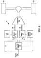
- FIG. 1is a schematic view of a hybrid vehicle in accordance with a first embodiment of the invention
- FIG. 2is a schematic view of a hybrid vehicle in accordance with a second embodiment of the invention.
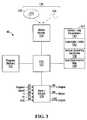
- FIG. 3is a schematic view of a processor circuit for use it the hybrid vehicle shown in FIG. 2 ;
- FIG. 4is a graphical depiction of a fuel consumption map for an engine used in the hybrid vehicle shown in FIG. 2 ;
- FIG. 5is a graphical depiction of the a storage element lifetime as a function of state of charge, for a storage element used in the hybrid vehicle shown in FIG. 2 ;
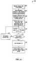
- FIG. 6is a flowchart of a process for producing operating costs executed by the processor circuit shown in FIG. 3 ;
- FIG. 7is a graphical depiction of operating costs for the hybrid vehicle shown in FIG. 2 ;
- FIG. 8is a schematic view of a hybrid vehicle in accordance with an alternate embodiment of the invention.
- an apparatus for managing power in a hybrid vehicle 11is shown generally at 10 .
- the hybrid vehicle 11includes an engine 12 , an electric motor-generator 14 , and an energy storage element 16 coupled to the motor.
- the apparatus 10includes a processor circuit 18 , which is operably configured to receive a request signal 20 to supply operating power to drive the vehicle 11 .
- the processor circuit 18is operably configured to respond to the request by selecting an apportionment of operating power between the engine 12 and the motor-generator 14 from among a plurality of apportionments having respective operating costs such that the selected apportionment is associated with a minimum operating cost.
- the operating costincludes at least an engine fuel consumption cost and a storage element lifetime cost.
- the processor circuit 18is operably configured to cause power to be supplied by at least one of the engine 12 and the motor-generator 14 in accordance with the selected apportionment.
- the vehicleincludes a transmission 22 and a pair of drive wheels 24 .
- the engine 12is coupled to the transmission 22 through a first shaft 26
- the motor-generator 14is in coupled to the transmission via a second shaft 28 .
- the first and second shafts 26 and 28couple power from the engine 12 and the motor-generator 14 respectively, through the transmission 22 , to the drive wheels 24 , thus supplying operating power to drive the vehicle 11 .
- operating powermay be supplied by either the engine 12 , or the motor-generator 14 , or by the engine and the motor in combination.
- the hybrid vehicle 11also includes a fuel reservoir 30 , which is in communication with the engine 12 for supplying fuel to operate the engine 12 .
- the engine 12further includes an interface 32 which is in communication with the processor circuit 18 for receiving an engine power control signal from the processor circuit 18 to control an amount of power coupled to the transmission 22 through the first shaft 26 .
- the storage element 16is in communication with the motor-generator 14 for supplying electrical energy to the motor.
- the motor-generator 14further includes an interface 34 for receiving a motor power control signal from the processor circuit 18 to control an amount of mechanical power supplied by the motor-generator 14 to the second shaft 28 and to control an amount of electrical power generated by the motor-generator in response to mechanical energy provided by the second shaft.
- the motor-generator 14thus has a motor mode in which it converts energy from the storage element 16 into mechanical energy at the second shaft 28 and a generator mode in which it receives mechanical power from the second shaft and converts it into electrical energy for storage in the storage element 16 .
- the vehicle 11may include a separate generator for charging the storage element 16 , in which case the motor-generator 14 would operate only in the motor-mode.
- the mechanical power provided by the second shaft 28may be generated by the drive wheels 24 while maintaining or reducing a speed of the vehicle 11 , and coupled through the transmission 22 to the second shaft 28 .
- the mechanical powermay be generated by the engine 12 , coupled through the first shaft 26 to the transmission 22 , which may be configured to couple the power to the second shaft 28 .
- the hybrid vehicle 50includes an engine 52 , an electric motor-generator 54 , a transmission 56 , and a clutch 64 .
- the clutch 64includes a first friction disk 66 and a second friction disk 63 . The clutch 64 is engaged by causing the friction disks 66 and 63 to be brought into contact with each other and the clutch is disengaged by causing the friction disks to be separated.
- the hybrid vehicle 50includes a first shaft 58 for coupling the motor-generator 54 to the transmission 56 , and a second shaft 60 for coupling the motor to the first friction disk 66 of the clutch 64 .
- the second shaft 60 and the first shaft 58are coupled to opposite ends of a rotor (not shown) in the motor-generator 54 such that power may be coupled between the first and second shafts 60 and 58 , through the motor-generator 54 .
- the hybrid vehicle 50also includes a third shaft 62 for coupling the engine 52 to the second friction disk 63 of the clutch 64 .
- the clutch 64operates to cause the engine 52 to be selectively engaged or disengaged from the second shaft 60 .
- the motor-generator 54may be located between the transmission 56 and the drive wheels 24 , and the motor may be coupled to supply and receive power directly to or from the drive wheels.
- the motor-generator 54is in communication with the storage element 16 for receiving electrical energy therefrom.
- the storage element 16may comprise a plurality of cells 17 , and may further include circuitry (not shown) for generating a state of charge (SOC) signal indicating a current SOC of the storage element.
- the cells 17 in the storage element 16may include electrochemical cells 17 , such as nickel metal hydride (NiMH) storage cells.
- the storage element 16may include a combination of electrochemical cells and/or a storage capacitor element, such as ultra-capacitor, for example.
- the motor-generator 54comprises a wound field direct current (DC) motor in which a magnetic field is provided by energizing field coils (not shown). The field coils may be energized using electrical energy supplied from the storage element 16 .
- the motormay include a permanent magnet DC motor, or an alternating current motor (AC).
- the motor-generator 54is operable to couple mechanical power to the first shaft 58 when receiving electrical energy from the storage element 16 , and is operable as a generator when mechanical power is coupled to the motor through the first shaft 58 for generating electrical energy for charging the storage element 16 .
- the hybrid vehicle 50optionally includes a power converter 55 for converting the electrical energy received from the storage element into a form suitable for operating the motor-generator 54 .
- the power converter 55may include an inverter for converting direct current (DC) from the storage element 16 into alternating current (AC) for operating an AC motor.
- the power converter 55may be a DC-DC converter for converting the DC current from a first voltage level associated with the storage element 16 , to a second voltage level suitable for operating the motor.
- the hybrid vehicle 50further includes an operator input device 70 for producing a drive signal representing an operator requested power.
- the operator input devicemay include a foot actuated actuator, for example.
- the hybrid vehicle 50also includes a speed sensor 72 which is in communication with the drive wheels 24 for producing a speed signal representing a speed of the drive wheels 24 .
- the processor circuit 80includes a central processing unit (CPU) 120 , a program memory 122 , a parameter memory 124 , a media reader 126 , and an input/output port (I/O) 128 .
- the program memory 122 , the parameter memory 124 , the media reader 126 and the I/O 128are all in communication with the CPU 120 .
- the I/O 128includes an input 82 for receiving a request signal, an input 84 for receiving a speed signal, an input 90 for receiving temperature signals, an input 94 for receiving a fuel consumption signal, and an input 86 for receiving the SOC signal form the storage element 16 .
- the I/O 128also includes the output 96 for producing an engine power control signal, an output 98 for producing a motor power control signal, and an output 104 for producing a clutch control signal.
- the media reader 126facilitates loading program codes into the program memory 122 from a computer readable medium 130 , such as a CD-ROM disc 132 , or a computer readable signal 134 , such as may be received from a network such as a telephone network or the internet, for example.
- a computer readable medium 130such as a CD-ROM disc 132
- a computer readable signal 134such as may be received from a network such as a telephone network or the internet, for example.
- the parameter memory 124includes a store 136 for storing data representing an engine fuel consumption map, a store 138 for storing data representing a set of operating conditions of the hybrid vehicle 50 , a store 140 for storing data representing constraint limits for the vehicle, and a store 142 for storing control loop parameters.
- the input 82 of the processor circuitis in communication with the operator input device 70 for receiving the drive signal, the input 84 is in communication with the speed sensor 72 for receiving the speed signal, and the input 86 is in communication with the storage element 16 for receiving the SOC signal.
- the engine 52also includes a temperature sensor 88 for sensing an operating temperature of the engine
- the motor-generator 54includes a temperature sensor 57 for sensing an operating temperature of the motor
- the power converter 55includes a temperature sensor 59 for sensing an operating temperature of the power converter.
- the input 90 of the processor circuit 80is in communication with the temperature sensors 88 , 57 , and 59 for receiving the respective temperature signals.
- the engine 52further includes a fuel consumption sensor 92 for generating a signal representing an actual fuel consumption of the engine.
- the input 94 of the processor circuit 80is in communication with the fuel consumption sensor 92 for receiving the fuel consumption signal. Fuel is supplied to the engine 52 from the fuel reservoir 30 .
- the engine 52also includes an interface 100 in communication with the output 96 of the processor circuit 80 for receiving the engine power control signal to control an amount of power coupled to the third shaft 62 .
- the motor-generator 54includes an interface 102 in communication with the output 98 of the processor circuit for receiving the motor power control signal for controlling an amount of mechanical power supplied by the motor-generator 54 to the first shaft 58 and to control an amount of electrical power generated by the motor-generator in response to mechanical energy provided by the first shaft.
- the clutch 64is in communication with the output 104 of the processor circuit 80 for receiving the clutch control signal.
- the clutch control signalhas states representing engagement and disengagement of the friction disks 63 and 66 .
- operating poweris supplied to the drive wheels 24 of the hybrid vehicle 50 through the transmission 56 .
- the clutch control signalis in the disengaged state
- the engineis decoupled from the second shaft 60 (and thus the first shaft 58 ), and the motor-generator 54 supplies operating power to the vehicle.
- the motor-generator 54receives electrical energy from the storage element 16 and produces operating power for the vehicle 50 in response to the motor power control signal received at the interface 102 from the output 98 the processor circuit 80 .
- the engine 52When the clutch control signal is in the engaged state, the engine 52 produces a first portion of the operating power in response to the engine power control signal received at the interface 100 from the processor circuit 80 , while the motor-generator 54 produces a second portion of the operating power in response to the motor power control signal received at the interface 102 from the processor circuit 80 .
- operating powermay be supplied by the engine 52 , in which case no electrical energy is supplied to the motor (or to the motor field coils) from the storage element 16 and the motor rotates freely, consuming only a small amount of energy due to residual magnetism and windage effects (i.e. when the motor is not operating as a generator).
- the motor-generator 54When it is desired to charge the storage element 16 , power is coupled to the motor-generator 54 through the first shaft 58 .
- the poweris supplied either by the engine 52 or by the drive wheels 24 .
- the drive wheels 24provide power to the first shaft 58 while reducing or maintaining the speed of the vehicle 50 .
- the power from the drive wheelsmay be coupled back to the motor-generator 54 for generating electrical energy, thus reducing an amount of conventional frictional braking required to operate the vehicle.
- the motorWhen the field coils of the motor-generator 54 are energized, the motor acts as an electrical energy generator for converting power on the first shaft 58 to electrical power for charging the storage element 16 .
- the torque required at the first shaft 58 to generate the electrical energyacts as a braking force on the drive wheels 24 .
- the motor-generator 54comprises, for example, a permanent magnet field DC motor
- operation as a generatoris contingent on whether or not current is drawn from the motor while the motor is receiving mechanical power.
- the power converter 55may be configured to enable or disable drawing of a charging current to charge the storage element 16 depending on whether braking is required.
- the required operating powermay be apportioned between the motor and the engine respectively, such that the motor supplies the first portion of the operating power and the engine supplies the second portion of the operating power.
- the apportionment of power between the motor and the enginefacilitates operation of the hybrid vehicles 11 and 50 such that a cost of operating the vehicles may be minimized.
- minimizing the operating costinvolves producing operating costs for a plurality of apportionments of a requested operating power between the engine 52 and the motor-generator 54 and selecting an apportionment from the plurality of apportionments corresponding to a minimum operating cost.
- the processor circuit 80then produces the engine power control signal at the output 96 and motor power control signal at the output 98 in accordance with the selected apportionment.
- the selected apportionment of poweris applied for a control period, after which the process is repeated for successive control periods, thus responding to operating changes on an ongoing basis.
- the processor circuit 80may cause the clutch control signal to assume the disengaged state causing the clutch 64 to be disengaged, thus allowing the engine to be stopped such that fuel is conserved.
- the engine 52may be restarted by engaging the clutch 64 to couple power to the third shaft 62 , thus starting the engine.
- the cost of operating the engine 52 to supply a quantity of operating power to the vehicleis related to an amount of fuel consumed from the fuel reservoir 30 .
- the engine 52may be configured to run on one or more of a variety of fuel supplies, including but not limited to, gasoline, diesel, biogas or other bio-fuels including cellulosic and other ethanols, propane etc.
- the map 160includes a surface function 162 which relates engine speed values 164 and engine torque values 166 to fuel consumption values 168 .
- data representing the map 160is stored in the store 136 in the parameter memory 124 of the processor circuit 80 .
- the datamay be stored as a look up table or a set of coefficients for a function defining the surface 162 .
- the fuel consumption data stored in the store 136is updated with actual fuel consumption values produced by the fuel consumption sensor 92 and received at the input 94 of the I/O 128 .
- the fuel consumption data stored in the store 136may be determined from test data for the engine 52 , or from standard test data for engines similar to the engine 52 .
- Fuel consumptionis also generally dependent on engine temperature.
- the effect of engine temperature on fuel consumptionis taken into account by storing a cold engine temperature fuel consumption map and a hot engine temperature fuel consumption map in the store 136 of the parameter memory 124 .
- the temperature signal from the temperature sensor 88is received at the input 90 of the I/O 128 and the actual engine temperature is used to interpolate between the hot and cold fuel consumption values to obtain a temperature corrected fuel consumption value.
- OC engis the operating cost of the engine
- Power engis an apportionment of power to be supplied by the engine 52
- Fuel engis the fuel consumption value corresponding to the apportionment of power.
- Electrical energy for operating the motor-generator 54is supplied from the storage element 16 .
- the cost of operating the motor-generator 54may be related to the cost of replacing energy supplied from the storage element 16 .
- Electrical energy supplied from the storage element 16may be replaced by coupling regenerative braking power from the drive wheels 24 to the motor-generator 54 , or by coupling mechanical power supplied by the engine 52 to the motor-generator 54 , to generate electrical energy for charging the storage element.
- OC motis the operating cost of the motor
- Power motis the apportionment of power to be supplied by the motor
- Fuel equis an equivalent fuel consumption amount that will be required by the engine 52 to replace the quantity of energy in the storage element 16 in a future control period.
- Fuel equis calculated taking into account the lowest fuel consumption rate (from the map shown in FIG. 4 ) and the electrical losses (or efficiencies) in the storage element 16 and the motor-generator 54 as follows:
- Fuel equMin ⁇ ( Fuel eng ) - Fuel free_brake ⁇ mot ⁇ ⁇ store Eqn ⁇ ⁇ 3
- Fuel free — brakeis an amount of energy received from regenerative braking of the vehicle 50 during a prior control period, expressed as an equivalent fuel consumption
- ⁇ motis the electrical efficiency of the motor-generator 54
- ⁇ storeis the charging efficiency of the storage element.
- the quantity of the energy available from regenerative brakingwill vary in accordance with driving habits of the vehicle operator, road and environmental conditions etc. Accordingly, in this embodiment the quantity of energy is calculated in real time using the following equation:
- E free_brake1 T ⁇ ⁇ 0 T ⁇ Power free_brake ⁇ ⁇ d t Eqn ⁇ ⁇ 4
- Tis a control loop repetition time
- Power free — brakeis the instantaneous regenerative braking power available at any time t.
- the regenerative braking energy calculated in Eqn 4is available for use during the next control period.
- the quantity E free — brakemay be converted into an equivalent fuel consumption Fuel free — brake using standard values for the potential energy per unit mass for the fuel type contained in the fuel reservoir 30 .
- the fuel consumption of the engine 52thus includes a first component related to supplying a portion of operating power to the drive wheels 24 from the engine, and a second component, which is attributed to the motor-generator 54 , for supplying power to the motor in order to charge the storage element 16 to replace energy discharged therefrom in a previous control period.
- Commonly available storage elementshave an associated lifetime, after which the element becomes unsuitable for further use.
- this lifetimemay be prolonged by operating the element as close as possible to an optimal state of charge (SOC), for example at 60% of full capacity.
- SOCstate of charge
- operating the storage element 16 at close to optimal SOCresults in a longer lifetime and thus the lowest storage element lifetime cost.
- a graphical depiction of an exemplary NiMH storage element lifetime as a function of SOCis shown generally at 180 .
- the longest lifetimeis achieved by maintaining the battery SOC at 60%. Any deviation from 60% SOC results in a storage element lifetime penalty or reduction.
- the storage elementis generally operated over a range of SOC values, for example from 40% SOC to 80% SOC for a NiMH storage element.
- OC storageW s .
- W sis a weighting factor.
- the weighting factor W smay be used to account for the relative cost of fuel versus the relative cost of storage element replacement. For example, if fuel prices drop the weighting factor W s may be increased to accord greater weight to the storage element operating costs, while if storage element replacement prices drop, the weighting W s may be reduced to accord less weight to the storage element operating costs.
- the SOCis at a point 182 (corresponding to a SOC of approximately 70%)
- the ASOCshown by the arrow 184
- K1000 W per % SOC
- the required power to return to optimal SOCis ⁇ 10000 W (the negative sign indicates a discharge of the storage element 16 is required).
- the operating cost calculated from Eqn 5is thus zero, since discharging 10000 W from the storage element causes the SOC to be at optimal SOC.
- Lower or higher motor power apportionmentswill result in positive storage element operating costs since the SOC will not be at optimal SOC at the end of the control period.
- OCis the overall operating cost.
- the overall operating cost functionis evaluated for each of a plurality of apportionments of power between the engine 52 and the motor-generator 54 and the power apportionment corresponding to a minimum operating cost is selected.
- the plurality of apportionmentsare identified by evaluating operational constraints associated with the engine 52 , the motor-generator 54 , and the storage element 16 prior to each control period, such that power apportionments that do not meet the constraints are not considered.
- Some of the constraintsmay be set by the manufacturer (e.g. maximum storage element temperature, maxim terminal voltage, and/or minimum terminal voltage), however in general the constraints also depend on the current operating conditions of the vehicle.
- the engine 52has a constraint related to the maximum power that may be supplied, which is a function of the engine speed and torque. Accordingly, an apportionment which results in an engine torque or speed that is greater than the corresponding maximum is not further considered.
- the motor-generator 54also has a constraint related to the maximum mechanical power that may be supplied which may be expressed as a function of motor temperature, motor current, motor voltage, motor speed and motor torque. When regenerative braking power is available, the motor-generator 54 has a further constraint related to the maximum mechanical power that may be received by the motor, which is a function of motor temperature, motor current, motor voltage, motor speed and motor torque.
- Another constraint for the motor-generator 54occurs when a power apportionment to the motor will result in overcharging of the storage element (i.e. the resulting SOC at the end of the control period would be above the maximum SOC recommended by the storage element manufacturer). Similarly, a constraint for the motor-generator 54 occurs when a motor power apportionment will result in discharging the storage element 16 beyond a minimum SOC set by the manufacturer.
- the storage element 16generally has constraints related to maximum charging power and maximum discharging power.
- the maximum charging power constraint for a NiMH batteryis a function of battery temperature, SOC, the terminal voltage of the battery, maximum terminal voltage, and maximum charging current.
- the maximum changing powervaries from control period to control period depending on the aforementioned factors.
- the maximum discharging power for a NiMH batteryis a function of battery temperature, SOC, the terminal voltage of the battery, minimum terminal voltage, and maximum discharging current.
- FIG. 6a flow chart depicting blocks of code for directing the processor circuit 80 (shown in FIG. 2 ) to manage power in the hybrid vehicle 50 , is shown generally at 200 .
- the blocksgenerally represent codes that may be read from the computer readable medium 130 , and stored in the program memory 122 , for directing the CPU 120 to perform various functions related to managing apportionment of power in the vehicle 50 .
- the actual code to implement each blockmay be written in any suitable program language, such as C, C++ and/or assembly code, for example.
- the processbegins with a first block of codes 202 which directs the processor circuit 80 to receive the drive signal from the operator input device at the input 82 and to receive the speed from the speed sensor 72 at the input 84 of the I/O 128 .
- the processcontinues at block 204 , which directs the CPU 120 to read a current set of operating conditions of the hybrid vehicle 50 from the store 138 in the parameter memory 124 .
- the current operating conditionsgenerally include, for example, conditions such as speed and torque of the engine 52 and the motor-generator 54 , SOC & terminal voltage of the storage element 16 , temperatures of the engine, motor, power converter 55 , and storage element, etc.
- the block 204may also include codes for directing the processor to calculate a current vehicle acceleration from the speed values.
- Block 204further directs the processor circuit 80 to calculate an amount of operating power to be supplied to drive the vehicle 50 for the next control loop period.
- the amount of operating power to be suppliedis calculated in response to the drive signal received from the operator input device 70 and the current operating conditions of the vehicle. Accordingly, the amount of operating power to be supplied may not meet the operator requested power, depending on current operating conditions of the vehicle 50 . For example, if the engine 52 and motor-generator 54 are already delivering maximum power, a request received from the operator input device 70 to supply more power will not be met.
- Block 206directs the processor circuit 80 to evaluate operating constraints for the next control loop period for the engine 52 , motor-generator 54 , and storage element 16 .
- the constraintsare evaluated based on operating conditions read at block 204 .
- Block 206may further direct the processor circuit 80 to read constraint limits from the store 140 in the parameter memory 124 , which may include manufacturer and/or other constraint information for the engine 52 , the motor-generator 54 and/or the storage element 16 .
- the processcontinues at block 208 which directs the processor circuit 80 to read control loop parameters from the store 142 in the parameter memory 124 .
- the control loop parametersmay include, for example, a power increment value which determines the number of different apportionments of power that will be evaluated. Evaluating a greater number of apportionments may provide more precise apportionments, but since the operating costs are evaluated in real time while operating the vehicle, evaluating a large number of apportionments may require provision of faster processing speed for the processor circuit 80 .
- Block 208further directs the processor circuit to initialize a power apportionment variable to a first power apportionment.
- Block 210then directs the processor circuit to calculate the operating costs for the engine 52 , motor-generator 54 , and storage element 16 for the first power apportionment.
- Block 212if the present power apportionment is not the last power apportionment, the process continues at block 214 , where the power apportionment variable is set to the next power apportionment. Blocks 210 , 212 and 214 are then repeated for successive power apportionments.
- a graphical depiction of the operating costs for apportionment of a required power of 50 kWis shown generally at 240 .
- Power apportionmentsare plotted on the x-axis as pairs of power apportionments 242 , each pair including an engine power apportionment 244 and a motor power apportionment 246 .
- a curve 248represents the engine operating cost calculated in accordance with Eqn 1 for the power apportionments
- a curve 250represents motor operating costs calculated in accordance with Eqn 2
- a curve 252represents storage element lifetime costs calculated in accordance with Eqn 5.
- a curve 254represents the overall operating cost function calculated in accordance with Eqn 6, for each power apportionment 242 .
- Eqn 6the overall operating cost function calculated in accordance with Eqn 6
- the processcontinues at block 216 .
- the processor circuitis directed to execute an optimization search to find an apportionment 242 corresponding to the minimum operating cost in the curve 254 .
- a golden section searchis used to find the minimum operating cost.
- the golden section searchis a bracketing technique, which may be applied to a set of values to find a single minimum value in the set between an upper bound bracket value and a lower bound bracket value.
- the searchbegins by selecting upper and lower bound brackets at end points of the range of power apportionments 242 .
- the upper and lower bound bracketsare then successively narrowed until a minimum is found.
- the techniquederives its name from the golden ratio, which has been found to be an effective bracketing ratio.
- Applying the golden ratioinvolves selecting an intermediate apportionment between the upper bound bracket and the lower bound bracket that is 0.38197 from one end and 0.61803 from the other end, and then moving the bracket having a greater corresponding operating cost (curve 254 ) to the intermediate apportionment, which then becomes the new upper or lower bound bracket. The process is then repeated until the minimum operating cost value coincides with either the upper bound bracket or the lower bound bracket, in which case the lesser of the cost values corresponding to the upper and lower bound brackets is the minimum operating cost value.
- the application of the golden section search technique to finding the minimum operating costis described with reference to FIG. 7 , by assuming that the number of apportionments is six (i.e the apportionments [0,50],[10,40],[20,30],[30,20],[40,10], and [50,0]).
- the first step in the application of the techniqueis to select apportionment pair [0,50] as the lower bound bracket and [50,0] as the upper bound bracket, and to calculate an intermediate point 256 between the upper bound bracket and the lower bound bracket using the golden section ratio of 0.38197, yielding an intermediate apportionment of [20,30], which is closest to the ratio 0.38197.
- a new lower bound bracket of [20,30]is selected.
- the golden ratiois again applied to find an intermediate point 258 , which in this case is closest to the apportionment [30,20] with an operating cost value of approximately 0.066.
- the lower bound bracket [20,30]has a higher cost value and accordingly, the new lower bound bracket is chosen at [30,20]. Selecting a further intermediate point in accordance with the golden ratio yields an intermediate point 260 , which is close to apportionment [40,10].
- the minimum of these two valuesrepresents the minimum operating cost at 262 , which in this case is approximately 0.061 and corresponds to an apportionment of [40,10].
- the golden section searchallows quick convergence on a minimum value in a plurality of values having a single minimum between an upper bound and a lower bound.
- alternative optimization techniquessuch as a linear search, for example may be used to find the minimum operating cost.
- the processcontinues at block 218 , which directs the processor circuit to cause the engine power control signal and the motor power control signal to be generated at respective outputs 96 and 98 of the I/O 128 .
- the enginesupplies 40 kW of power and the motor supplies 10 kW, and thus the processor circuit 80 also causes the clutch control signal to be produced at the output 104 to cause the clutch 64 to be engaged such that the engine is coupled to the second shaft 60 .
- including a storage element lifetime cost and fuel consumption costs in selecting the apportionment of power between the engine and the motorfacilitates operation of the vehicle such that fuel consumption is reduced without reducing the lifetime of the battery.
- the hybrid vehicle 280includes an engine 282 , a transmission 284 , a motor 286 , and a storage element 288 .
- the engine 282is coupled to the drive wheels 24 through the transmission 284 .
- the transmissionincludes a take-off point 290 for coupling to the motor 286 .
- the motor 286is coupled to a storage element 288 for supplying and receiving electrical energy as described above.
- the take off point 290 and motor 286are configured in a manner similar to a starter motor in a conventional internal combustion engine vehicle, although the motor 286 is generally larger than a conventional starter motor and has a higher power capability.
- One example of this embodimentis a so-called “mild hybrid” in which the engine 282 shuts down when the vehicle is stopped, and the motor 286 restarts the engine when the operator produces a drive signal at an operator input device 292 , thus conserving fuel when stopped.
- the processor circuit 80 shown in FIG. 2may be implemented generally as described above to manage power in the hybrid vehicle 280 .
Landscapes
- Engineering & Computer Science (AREA)
- Mechanical Engineering (AREA)
- Transportation (AREA)
- Power Engineering (AREA)
- Combustion & Propulsion (AREA)
- Chemical & Material Sciences (AREA)
- Automation & Control Theory (AREA)
- Life Sciences & Earth Sciences (AREA)
- Sustainable Development (AREA)
- Sustainable Energy (AREA)
- General Engineering & Computer Science (AREA)
- Electric Propulsion And Braking For Vehicles (AREA)
- Hybrid Electric Vehicles (AREA)
- Control Of Vehicle Engines Or Engines For Specific Uses (AREA)
- Seal Device For Vehicle (AREA)
Abstract
Description
OCeng=Fueleng·Powereng Eqn 1
OCmot=Fuelequ·Powermot Eqn 2
OCstorage=Ws.|K·ΔSOC−Powermot| Eqn 5
OC=OCeng+OCmot+OCstorage Eqn 6
Claims (55)
Priority Applications (8)
| Application Number | Priority Date | Filing Date | Title |
|---|---|---|---|
| US11/515,175US7826939B2 (en) | 2006-09-01 | 2006-09-01 | Method, apparatus, signals, and medium for managing power in a hybrid vehicle |
| CA2661718ACA2661718C (en) | 2006-09-01 | 2007-08-30 | Method, apparatus, signals, and medium for managing power in a hybrid vehicle |
| PCT/CA2007/001516WO2008025147A1 (en) | 2006-09-01 | 2007-08-30 | Cost minimization for hybrid vehicle power management |
| ES07800541TES2373169T3 (en) | 2006-09-01 | 2007-08-30 | APPARATUS AND PROCEDURE FOR MANAGING POWER IN A HYBRID VEHICLE. |
| EP07800541AEP2062220B1 (en) | 2006-09-01 | 2007-08-30 | Apparatus and method for managing power in a hybrid vehicle |
| AT07800541TATE528189T1 (en) | 2006-09-01 | 2007-08-30 | DEVICE AND METHOD FOR POWER CONTROL IN A HYBRID VEHICLE |
| US12/925,403US8738203B2 (en) | 2006-09-01 | 2010-10-19 | Method, apparatus, signals, and medium for managing power in a hybrid vehicle |
| US14/273,305US9365132B2 (en) | 2006-09-01 | 2014-05-08 | Method, apparatus, signals, and medium for managing power in a hybrid vehicle |
Applications Claiming Priority (1)
| Application Number | Priority Date | Filing Date | Title |
|---|---|---|---|
| US11/515,175US7826939B2 (en) | 2006-09-01 | 2006-09-01 | Method, apparatus, signals, and medium for managing power in a hybrid vehicle |
Related Child Applications (1)
| Application Number | Title | Priority Date | Filing Date |
|---|---|---|---|
| US12/925,403ContinuationUS8738203B2 (en) | 2006-09-01 | 2010-10-19 | Method, apparatus, signals, and medium for managing power in a hybrid vehicle |
Publications (2)
| Publication Number | Publication Date |
|---|---|
| US20080059013A1 US20080059013A1 (en) | 2008-03-06 |
| US7826939B2true US7826939B2 (en) | 2010-11-02 |
Family
ID=39135466
Family Applications (3)
| Application Number | Title | Priority Date | Filing Date |
|---|---|---|---|
| US11/515,175Active2029-08-26US7826939B2 (en) | 2006-09-01 | 2006-09-01 | Method, apparatus, signals, and medium for managing power in a hybrid vehicle |
| US12/925,403Active2028-10-07US8738203B2 (en) | 2006-09-01 | 2010-10-19 | Method, apparatus, signals, and medium for managing power in a hybrid vehicle |
| US14/273,305ActiveUS9365132B2 (en) | 2006-09-01 | 2014-05-08 | Method, apparatus, signals, and medium for managing power in a hybrid vehicle |
Family Applications After (2)
| Application Number | Title | Priority Date | Filing Date |
|---|---|---|---|
| US12/925,403Active2028-10-07US8738203B2 (en) | 2006-09-01 | 2010-10-19 | Method, apparatus, signals, and medium for managing power in a hybrid vehicle |
| US14/273,305ActiveUS9365132B2 (en) | 2006-09-01 | 2014-05-08 | Method, apparatus, signals, and medium for managing power in a hybrid vehicle |
Country Status (6)
| Country | Link |
|---|---|
| US (3) | US7826939B2 (en) |
| EP (1) | EP2062220B1 (en) |
| AT (1) | ATE528189T1 (en) |
| CA (1) | CA2661718C (en) |
| ES (1) | ES2373169T3 (en) |
| WO (1) | WO2008025147A1 (en) |
Cited By (8)
| Publication number | Priority date | Publication date | Assignee | Title |
|---|---|---|---|---|
| US20090113874A1 (en)* | 2007-11-02 | 2009-05-07 | Caterpillar Inc. | System and method for electrically regenerating a particulate filter assembly of a generator set |
| US20110043165A1 (en)* | 2009-08-20 | 2011-02-24 | Gm Global Technology Operations, Inc. | Method for charging a plug-in electric vehicle |
| US20130166182A1 (en)* | 2011-01-20 | 2013-06-27 | Hino Motors, Ltd. | Regenerative control device, hybrid vehicle,regenerative control method, and computer program |
| US20130332015A1 (en)* | 2010-09-04 | 2013-12-12 | Clement Dextreit | Controller and method of control of a hybrid electric vehicle |
| US8639403B2 (en) | 2010-12-29 | 2014-01-28 | Cummins Inc. | Modularized hybrid power train control |
| US9187100B2 (en) | 2010-12-20 | 2015-11-17 | Cummins Inc. | Hybrid power train flexible control integration |
| US20160185335A1 (en)* | 2014-12-30 | 2016-06-30 | GM Global Technology Operations LLC | Hybrid powertrain with mechatronic actuator assembly and method of controlling the same |
| US10618423B2 (en)* | 2017-09-15 | 2020-04-14 | Ford Global Technologies, Llc | Isolated dual bus hybrid vehicle drivetrain |
Families Citing this family (35)
| Publication number | Priority date | Publication date | Assignee | Title |
|---|---|---|---|---|
| CA2650224C (en) | 2006-05-09 | 2014-02-25 | Azure Dynamics Inc. | Process and apparatus for reducing nitrogen oxide emissions in genset systems |
| US8346416B2 (en) | 2006-06-26 | 2013-01-01 | Azure Dynamics, Inc. | Method, apparatus, signals and media, for selecting operating conditions of a genset |
| JP4780402B2 (en)* | 2006-06-27 | 2011-09-28 | 株式会社デンソー | Vehicle power supply |
| JP2008125318A (en)* | 2006-11-15 | 2008-05-29 | Toyota Motor Corp | VEHICLE, DRIVE DEVICE, AND CONTROL METHOD THEREOF |
| US7983823B2 (en)* | 2007-09-11 | 2011-07-19 | GM Global Technology Operations LLC | Method and control architecture for selection of optimal engine input torque for a powertrain system |
| US7988591B2 (en) | 2007-09-11 | 2011-08-02 | GM Global Technology Operations LLC | Control architecture and method for one-dimensional optimization of input torque and motor torque in fixed gear for a hybrid powertrain system |
| US8010247B2 (en)* | 2007-11-03 | 2011-08-30 | GM Global Technology Operations LLC | Method for operating an engine in a hybrid powertrain system |
| TWI346056B (en)* | 2007-12-07 | 2011-08-01 | Ind Tech Res Inst | Mixed type vehicle power system and method of forming multidimentional data of fuel consumption |
| FR2935123B1 (en)* | 2008-08-20 | 2010-08-27 | Renault Sas | HYBRID POWER UNIT CONTROL SYSTEM FOR MOTOR VEHICLE, AND ASSOCIATED METHOD |
| DE102008042228A1 (en)* | 2008-09-19 | 2010-04-01 | Robert Bosch Gmbh | Method for adjusting a motor drive device in a motor vehicle |
| US8823203B2 (en) | 2009-11-12 | 2014-09-02 | Denso Corporation | Controller for engine |
| US8612074B2 (en)* | 2010-05-07 | 2013-12-17 | GM Global Technology Operations LLC | Regenerative braking control in vehicles |
| US20120203404A1 (en)* | 2011-02-04 | 2012-08-09 | GM Global Technology Operations LLC | Method for heating hybrid powertrain components |
| CA2847666A1 (en)* | 2011-09-05 | 2013-03-14 | Honda Motor Co., Ltd. | Control system and control method for hybrid vehicle |
| ES2383778A1 (en)* | 2012-03-29 | 2012-06-26 | Universidad Politécnica de Madrid | Control system for multi-hybrid configurations in a vehicle (Machine-translation by Google Translate, not legally binding) |
| US9399461B2 (en)* | 2012-05-07 | 2016-07-26 | Ford Global Technologies, Llc | Opportunistic charging of hybrid vehicle battery |
| DE102012107788B4 (en)* | 2012-08-23 | 2015-05-07 | Deutsches Zentrum für Luft- und Raumfahrt e.V. | Energy management of a system according to an economic market model approach |
| KR102165371B1 (en)* | 2013-03-14 | 2020-10-14 | 알리손 트랜스미션, 인크. | System and method for engine driveline disconnect during regeneration in hybrid vehicles |
| WO2014158846A1 (en)* | 2013-03-14 | 2014-10-02 | Allison Transmission, Inc. | System and method for power management during regeneration mode in hybrid electric vehicles |
| EP2969689B1 (en)* | 2013-03-14 | 2022-12-07 | Allison Transmission, Inc. | System and method for optimizing power consumption in a hybrid electric vehicle |
| US9296390B2 (en)* | 2013-03-15 | 2016-03-29 | Ford Global Technologies, Llc | Hybrid vehicle exhaust diagnostics |
| JP6140534B2 (en)* | 2013-05-31 | 2017-05-31 | 株式会社Subaru | Vehicle control device |
| JP5829652B2 (en)* | 2013-07-02 | 2015-12-09 | 本田技研工業株式会社 | Vehicle power supply |
| US9718454B2 (en) | 2013-11-21 | 2017-08-01 | Cummins Inc. | Hybrid controls architecture |
| US11981357B2 (en)* | 2014-04-16 | 2024-05-14 | Transportation Ip Holdings, Llc | System and method for vehicle operation |
| JP6268118B2 (en)* | 2015-04-01 | 2018-01-24 | 株式会社豊田中央研究所 | Control device for hybrid vehicle |
| KR101755798B1 (en)* | 2015-06-30 | 2017-07-07 | 현대자동차주식회사 | Device and method for controlling battery charge and discharge quantity in eco-friendly vehicle |
| JP6679989B2 (en)* | 2016-03-02 | 2020-04-15 | トヨタ自動車株式会社 | Control device for hybrid vehicle |
| US20190002117A1 (en) | 2017-06-30 | 2019-01-03 | General Electric Company | Propulsion system for an aircraft |
| DE102017212659B4 (en)* | 2017-07-24 | 2024-11-07 | Audi Ag | Method for operating an overall electrical on-board network, control unit and motor vehicle |
| WO2019084527A1 (en) | 2017-10-27 | 2019-05-02 | Quantum Industrial Development Corporation | External combustion engine series hybrid electric drivetrain |
| US11235751B2 (en) | 2018-01-12 | 2022-02-01 | Cummins Inc. | Optimizing diesel, reductant, and electric energy costs |
| TWI694406B (en)* | 2019-06-24 | 2020-05-21 | 國立臺灣師範大學 | Intelligent energy distribution method and system for multi-power source vehicles |
| JP7600916B2 (en)* | 2021-07-21 | 2024-12-17 | トヨタ自動車株式会社 | Information processing device and information processing method |
| CN113511111B (en)* | 2021-09-01 | 2024-04-16 | 潍柴动力股份有限公司 | Fuel cell system control method, device, equipment and readable storage medium |
Citations (59)
| Publication number | Priority date | Publication date | Assignee | Title |
|---|---|---|---|---|
| US2916635A (en) | 1956-05-29 | 1959-12-08 | Specialties Dev Corp | Means for controlling the speed of turbines |
| US3225542A (en) | 1964-03-16 | 1965-12-28 | Oilgear Co | Speed control system |
| US3261007A (en) | 1963-04-24 | 1966-07-12 | Continental Elektro Ind Ag | Measuring device for determining angular position |
| US4083052A (en) | 1976-06-16 | 1978-04-04 | Sangamo Electric Company | Electronic tachograph |
| US4407132A (en) | 1980-02-20 | 1983-10-04 | Daihatsu Motor Co., Ltd. | Control apparatus and method for engine/electric hybrid vehicle |
| US4475105A (en) | 1982-09-24 | 1984-10-02 | Tokyo Shibaura Denki Kabushiki Kaisha | System for detecting mechanical movement |
| JPH01144101A (en) | 1987-11-30 | 1989-06-06 | Mitsubishi Heavy Ind Ltd | Fuel cost minimum operation controller for co-generation plant |
| US4905544A (en)* | 1975-09-25 | 1990-03-06 | Ganoung David P | Powertrain control apparatus for improving fuel economy |
| GB2267364A (en) | 1992-05-28 | 1993-12-01 | Daimler Benz Ag | Method for controlling a hybrid drive which drives a vehicle |
| US5343970A (en) | 1992-09-21 | 1994-09-06 | Severinsky Alex J | Hybrid electric vehicle |
| US5345761A (en) | 1993-12-02 | 1994-09-13 | Ford Motor Company | Energy management system for hybrid vehicle |
| US5547433A (en) | 1996-05-09 | 1996-08-20 | Yang; Tai-Her | Distributed differential coupling combined power system |
| EP0867323A2 (en) | 1997-03-24 | 1998-09-30 | Toyota Jidosha Kabushiki Kaisha | Energy flow management in hybrid vehicle power output apparatus |
| US5898282A (en) | 1996-08-02 | 1999-04-27 | B.C. Research Inc. | Control system for a hybrid vehicle |
| US5939794A (en) | 1995-07-25 | 1999-08-17 | Nippon Soken, Inc. | Engine control system for hybrid vehicle |
| US6009965A (en) | 1997-08-25 | 2000-01-04 | Honda Giken Kogyo Kabushiki Kaisha | Torque shock alleviating device in hybrid vehicle |
| US6083138A (en) | 1998-03-20 | 2000-07-04 | Nissan Motor Co., Ltd. | Hybrid drive control system for vehicle |
| US6098734A (en) | 1996-06-06 | 2000-08-08 | Isuzu Ceramics Research Institute Co., Ltd. | Hybrid powered automobile with controller |
| US6242873B1 (en) | 2000-01-31 | 2001-06-05 | Azure Dynamics Inc. | Method and apparatus for adaptive hybrid vehicle control |
| US6266956B1 (en) | 1998-12-22 | 2001-07-31 | Toyota Jidosha Kabushiki Kaisha | Exhaust emission control system of hybrid car |
| US6319168B1 (en) | 2000-04-25 | 2001-11-20 | General Motors Corporation | Apparatus and method for active transmission synchronization and shifting |
| CA2351911A1 (en) | 2000-06-30 | 2001-12-30 | Ford Global Technologies, Inc. | Method and apparatus for determining the operational energy cost of a hybrid vehicle |
| US20020065165A1 (en) | 2000-10-31 | 2002-05-30 | Anders Lasson | Method and arrangement in a hybrid vehicle for maximizing efficiency by operating the engine at sub-optimum conditions |
| US6421599B1 (en) | 2001-08-09 | 2002-07-16 | Ford Global Technologies, Inc. | Control strategy for an internal combustion engine in a hybrid vehicle |
| WO2002058209A1 (en) | 2001-01-03 | 2002-07-25 | The Regents Of The University Of California | Method for controlling the operating characteristics of a hybrid electric vehicle |
| US6480767B2 (en)* | 2000-09-22 | 2002-11-12 | Nissan Motor Co., Ltd. | Control system for hybrid vehicle |
| US6519513B2 (en) | 2001-03-01 | 2003-02-11 | Hitachi, Ltd. | Hybrid vehicle control apparatus |
| US6555991B1 (en) | 2002-02-05 | 2003-04-29 | Andrew Michael Zettel | Battery operating condition dependent method and apparatus for controlling energy transfer between an energy bus and a system of batteries |
| US6574535B1 (en) | 2000-05-31 | 2003-06-03 | General Motors Corporation | Apparatus and method for active driveline damping with clunk control |
| US6662096B2 (en) | 2001-03-01 | 2003-12-09 | Nissan Motor Co., Ltd. | Vehicle drive system and vehicle controlling method |
| US20040020206A1 (en) | 2001-05-07 | 2004-02-05 | Sullivan Timothy J. | Heat energy utilization system |
| US6715572B2 (en) | 2001-06-01 | 2004-04-06 | Honda Giken Kogyo Kabushiki Kaisha | Control system for hybrid vehicle |
| US20040074682A1 (en) | 2000-11-23 | 2004-04-22 | Fussey Peter Michael | Hybrid powder sources distribution management |
| US6741923B2 (en) | 2002-05-16 | 2004-05-25 | Nissan Motor Co., Ltd. | Vehicle driving force control apparatus |
| US6768621B2 (en) | 2002-01-18 | 2004-07-27 | Solectria Corporation | Contactor feedback and precharge/discharge circuit |
| WO2004071800A1 (en) | 2003-02-06 | 2004-08-26 | Wavecrest Laboratories Llc | Adaptive electric vehicle |
| US20040164616A1 (en) | 2003-02-25 | 2004-08-26 | Denso Corporation | Method for controlling vehicular electric system |
| US20040174125A1 (en) | 2000-12-27 | 2004-09-09 | Transportation Techniques Llc | Method and apparatus for adaptive control of hybrid electric vehicle components |
| US6809429B1 (en) | 1998-04-21 | 2004-10-26 | The Regents Of The University Of California | Control method and apparatus for internal combustion engine electric hybrid vehicles |
| US20050024061A1 (en) | 1997-11-03 | 2005-02-03 | Michael Cox | Energy management system for automotive vehicle |
| US20050057098A1 (en) | 2002-02-28 | 2005-03-17 | Bouchon Nicolas Louis | Methods of supplying energy to an energy bus in a hybrid electric vehicle, and apparatuses, media and signals for the same |
| US6879054B2 (en) | 2002-03-15 | 2005-04-12 | Azure Dynamics Inc. | Process, apparatus, media and signals for controlling operating conditions of a hybrid electric vehicle to optimize operating characteristics of the vehicle |
| US20050080537A1 (en)* | 2003-10-14 | 2005-04-14 | Cawthorne William R. | Optimal selection of input torque considering battery utilization for a hybrid electric vehicle |
| US20050246076A1 (en) | 2004-04-30 | 2005-11-03 | Jyh-Shin Chen | Torque management algorithm for hybrid electric vehicles |
| US6991052B2 (en)* | 1998-03-19 | 2006-01-31 | Hitachi, Ltd. | Hybrid car |
| US7017348B2 (en) | 2003-04-09 | 2006-03-28 | Aisin Aw Co., Ltd. | Control device for a hybrid vehicle |
| US7024290B2 (en) | 2004-07-30 | 2006-04-04 | Ford Global Technologies, Llc | Active motor damping to mitigate electric vehicle driveline oscillations |
| US20060108163A1 (en) | 2004-11-25 | 2006-05-25 | Honda Motor Co., Ltd. | Control system for hybrid vehicle |
| US7178618B2 (en) | 2001-11-29 | 2007-02-20 | Toyota Jidosha Kabushiki Kaisha | Vehicular control apparatus and method |
| US20070074516A1 (en) | 2005-10-03 | 2007-04-05 | General Electric Company | Method of controlling bypass air split to gas turbine combustor |
| US7223203B2 (en) | 2004-09-01 | 2007-05-29 | Ford Global Technologies, Llc | Method of detecting torque disturbances in a hybrid vehicle |
| US20070149348A1 (en) | 2005-12-23 | 2007-06-28 | Holmes Alan G | Vehicle propulsion system |
| US20070262586A1 (en) | 2006-05-09 | 2007-11-15 | Nicolas Bouchon | Process and apparatus for reducing nitrogen oxide emissions in genset systems |
| US7315774B2 (en) | 2006-03-22 | 2008-01-01 | Gm Global Technology Operations, Inc. | Jerk management using multivariable active driveline damping |
| US20080122228A1 (en) | 2006-06-26 | 2008-05-29 | Wei Liu | Method, apparatus, signals and media, for selecting operating conditions of a genset |
| US20080236913A1 (en) | 2007-03-28 | 2008-10-02 | Kazuhiro Ichimoto | Power output apparatus and vehicle equipped with the same, and method for controlling power output apparatus |
| US7480555B2 (en) | 2004-12-16 | 2009-01-20 | Eaton Corporation | Method for controlling centrifugal clutch engagement using engine torque requests |
| US7562730B2 (en) | 2005-03-03 | 2009-07-21 | Toyota Jidosha Kabushiki Kaisha | Hybrid vehicle and control method of hybrid vehicle |
| US7577507B2 (en) | 2006-03-22 | 2009-08-18 | Gm Global Technology Operations, Inc. | Driveline lash estimation and clunk management using multivariable active driveline damping |
Family Cites Families (10)
| Publication number | Priority date | Publication date | Assignee | Title |
|---|---|---|---|---|
| DE2541991C3 (en) | 1975-09-20 | 1978-10-26 | Didier-Werke Ag, 6200 Wiesbaden | burner |
| US5547443A (en) | 1995-09-07 | 1996-08-20 | Chen; David | Rocking exercise device with two seats |
| JPH1144101A (en) | 1997-07-29 | 1999-02-16 | Onoda Co | Repairing reinforcement construction method of concrete structure |
| JPH11148387A (en) | 1997-09-15 | 1999-06-02 | Honda Motor Co Ltd | Control device for hybrid vehicles |
| US6098744A (en) | 1998-07-08 | 2000-08-08 | Isuzu Ceramics Research Institute Co., Ltd. | Thermal-and sound-insulating container of multilayer insulations |
| US6554088B2 (en)* | 1998-09-14 | 2003-04-29 | Paice Corporation | Hybrid vehicles |
| JP3300295B2 (en) | 1998-12-07 | 2002-07-08 | 本田技研工業株式会社 | Control device for hybrid vehicle |
| US6318168B1 (en)* | 1999-01-15 | 2001-11-20 | Kayden Instruments Inc. | Thermal dispersion probe with microcomputer controller |
| US6889126B2 (en) | 2003-04-22 | 2005-05-03 | Nissan Motor Co., Ltd. | Drive force control for hybrid electric vehicle |
| JP4622496B2 (en) | 2004-12-08 | 2011-02-02 | 株式会社デンソー | Electric power control device |
- 2006
- 2006-09-01USUS11/515,175patent/US7826939B2/enactiveActive
- 2007
- 2007-08-30EPEP07800541Apatent/EP2062220B1/enactiveActive
- 2007-08-30CACA2661718Apatent/CA2661718C/enactiveActive
- 2007-08-30WOPCT/CA2007/001516patent/WO2008025147A1/enactiveApplication Filing
- 2007-08-30ESES07800541Tpatent/ES2373169T3/enactiveActive
- 2007-08-30ATAT07800541Tpatent/ATE528189T1/ennot_activeIP Right Cessation
- 2010
- 2010-10-19USUS12/925,403patent/US8738203B2/enactiveActive
- 2014
- 2014-05-08USUS14/273,305patent/US9365132B2/enactiveActive
Patent Citations (63)
| Publication number | Priority date | Publication date | Assignee | Title |
|---|---|---|---|---|
| US2916635A (en) | 1956-05-29 | 1959-12-08 | Specialties Dev Corp | Means for controlling the speed of turbines |
| US3261007A (en) | 1963-04-24 | 1966-07-12 | Continental Elektro Ind Ag | Measuring device for determining angular position |
| US3225542A (en) | 1964-03-16 | 1965-12-28 | Oilgear Co | Speed control system |
| US4905544A (en)* | 1975-09-25 | 1990-03-06 | Ganoung David P | Powertrain control apparatus for improving fuel economy |
| US4083052A (en) | 1976-06-16 | 1978-04-04 | Sangamo Electric Company | Electronic tachograph |
| US4407132A (en) | 1980-02-20 | 1983-10-04 | Daihatsu Motor Co., Ltd. | Control apparatus and method for engine/electric hybrid vehicle |
| US4475105A (en) | 1982-09-24 | 1984-10-02 | Tokyo Shibaura Denki Kabushiki Kaisha | System for detecting mechanical movement |
| JPH01144101A (en) | 1987-11-30 | 1989-06-06 | Mitsubishi Heavy Ind Ltd | Fuel cost minimum operation controller for co-generation plant |
| GB2267364A (en) | 1992-05-28 | 1993-12-01 | Daimler Benz Ag | Method for controlling a hybrid drive which drives a vehicle |
| US5327992A (en) | 1992-05-28 | 1994-07-12 | Mercedes-Benz Ag | Method for controlling a hybrid drive which drives a vehicle |
| US5343970A (en) | 1992-09-21 | 1994-09-06 | Severinsky Alex J | Hybrid electric vehicle |
| US5345761A (en) | 1993-12-02 | 1994-09-13 | Ford Motor Company | Energy management system for hybrid vehicle |
| US5939794A (en) | 1995-07-25 | 1999-08-17 | Nippon Soken, Inc. | Engine control system for hybrid vehicle |
| US5547433A (en) | 1996-05-09 | 1996-08-20 | Yang; Tai-Her | Distributed differential coupling combined power system |
| US6098734A (en) | 1996-06-06 | 2000-08-08 | Isuzu Ceramics Research Institute Co., Ltd. | Hybrid powered automobile with controller |
| US5898282A (en) | 1996-08-02 | 1999-04-27 | B.C. Research Inc. | Control system for a hybrid vehicle |
| EP0867323A2 (en) | 1997-03-24 | 1998-09-30 | Toyota Jidosha Kabushiki Kaisha | Energy flow management in hybrid vehicle power output apparatus |
| US6009965A (en) | 1997-08-25 | 2000-01-04 | Honda Giken Kogyo Kabushiki Kaisha | Torque shock alleviating device in hybrid vehicle |
| US20050024061A1 (en) | 1997-11-03 | 2005-02-03 | Michael Cox | Energy management system for automotive vehicle |
| US6991052B2 (en)* | 1998-03-19 | 2006-01-31 | Hitachi, Ltd. | Hybrid car |
| US6083138A (en) | 1998-03-20 | 2000-07-04 | Nissan Motor Co., Ltd. | Hybrid drive control system for vehicle |
| US6809429B1 (en) | 1998-04-21 | 2004-10-26 | The Regents Of The University Of California | Control method and apparatus for internal combustion engine electric hybrid vehicles |
| US6266956B1 (en) | 1998-12-22 | 2001-07-31 | Toyota Jidosha Kabushiki Kaisha | Exhaust emission control system of hybrid car |
| US6242873B1 (en) | 2000-01-31 | 2001-06-05 | Azure Dynamics Inc. | Method and apparatus for adaptive hybrid vehicle control |
| US6319168B1 (en) | 2000-04-25 | 2001-11-20 | General Motors Corporation | Apparatus and method for active transmission synchronization and shifting |
| US6574535B1 (en) | 2000-05-31 | 2003-06-03 | General Motors Corporation | Apparatus and method for active driveline damping with clunk control |
| CA2351911A1 (en) | 2000-06-30 | 2001-12-30 | Ford Global Technologies, Inc. | Method and apparatus for determining the operational energy cost of a hybrid vehicle |
| US6480767B2 (en)* | 2000-09-22 | 2002-11-12 | Nissan Motor Co., Ltd. | Control system for hybrid vehicle |
| US6500089B2 (en) | 2000-10-31 | 2002-12-31 | Ford Global Technologies, Inc. | Method and arrangement in a hybrid vehicle for maximizing efficiency by operating the engine at sub-optimum conditions |
| US20020065165A1 (en) | 2000-10-31 | 2002-05-30 | Anders Lasson | Method and arrangement in a hybrid vehicle for maximizing efficiency by operating the engine at sub-optimum conditions |
| US20040074682A1 (en) | 2000-11-23 | 2004-04-22 | Fussey Peter Michael | Hybrid powder sources distribution management |
| US20040174125A1 (en) | 2000-12-27 | 2004-09-09 | Transportation Techniques Llc | Method and apparatus for adaptive control of hybrid electric vehicle components |
| WO2002058209A1 (en) | 2001-01-03 | 2002-07-25 | The Regents Of The University Of California | Method for controlling the operating characteristics of a hybrid electric vehicle |
| US6662096B2 (en) | 2001-03-01 | 2003-12-09 | Nissan Motor Co., Ltd. | Vehicle drive system and vehicle controlling method |
| US6519513B2 (en) | 2001-03-01 | 2003-02-11 | Hitachi, Ltd. | Hybrid vehicle control apparatus |
| US20040020206A1 (en) | 2001-05-07 | 2004-02-05 | Sullivan Timothy J. | Heat energy utilization system |
| US6715572B2 (en) | 2001-06-01 | 2004-04-06 | Honda Giken Kogyo Kabushiki Kaisha | Control system for hybrid vehicle |
| US6421599B1 (en) | 2001-08-09 | 2002-07-16 | Ford Global Technologies, Inc. | Control strategy for an internal combustion engine in a hybrid vehicle |
| US7178618B2 (en) | 2001-11-29 | 2007-02-20 | Toyota Jidosha Kabushiki Kaisha | Vehicular control apparatus and method |
| US6768621B2 (en) | 2002-01-18 | 2004-07-27 | Solectria Corporation | Contactor feedback and precharge/discharge circuit |
| US6555991B1 (en) | 2002-02-05 | 2003-04-29 | Andrew Michael Zettel | Battery operating condition dependent method and apparatus for controlling energy transfer between an energy bus and a system of batteries |
| US6909200B2 (en) | 2002-02-28 | 2005-06-21 | Azure Dynamics Inc. | Methods of supplying energy to an energy bus in a hybrid electric vehicle, and apparatuses, media and signals for the same |
| US20050057098A1 (en) | 2002-02-28 | 2005-03-17 | Bouchon Nicolas Louis | Methods of supplying energy to an energy bus in a hybrid electric vehicle, and apparatuses, media and signals for the same |
| US6879054B2 (en) | 2002-03-15 | 2005-04-12 | Azure Dynamics Inc. | Process, apparatus, media and signals for controlling operating conditions of a hybrid electric vehicle to optimize operating characteristics of the vehicle |
| US6741923B2 (en) | 2002-05-16 | 2004-05-25 | Nissan Motor Co., Ltd. | Vehicle driving force control apparatus |
| WO2004071800A1 (en) | 2003-02-06 | 2004-08-26 | Wavecrest Laboratories Llc | Adaptive electric vehicle |
| US20040164616A1 (en) | 2003-02-25 | 2004-08-26 | Denso Corporation | Method for controlling vehicular electric system |
| US7017348B2 (en) | 2003-04-09 | 2006-03-28 | Aisin Aw Co., Ltd. | Control device for a hybrid vehicle |
| US20050080537A1 (en)* | 2003-10-14 | 2005-04-14 | Cawthorne William R. | Optimal selection of input torque considering battery utilization for a hybrid electric vehicle |
| US20050246076A1 (en) | 2004-04-30 | 2005-11-03 | Jyh-Shin Chen | Torque management algorithm for hybrid electric vehicles |
| US7024290B2 (en) | 2004-07-30 | 2006-04-04 | Ford Global Technologies, Llc | Active motor damping to mitigate electric vehicle driveline oscillations |
| US7223203B2 (en) | 2004-09-01 | 2007-05-29 | Ford Global Technologies, Llc | Method of detecting torque disturbances in a hybrid vehicle |
| US20060108163A1 (en) | 2004-11-25 | 2006-05-25 | Honda Motor Co., Ltd. | Control system for hybrid vehicle |
| US7480555B2 (en) | 2004-12-16 | 2009-01-20 | Eaton Corporation | Method for controlling centrifugal clutch engagement using engine torque requests |
| US7562730B2 (en) | 2005-03-03 | 2009-07-21 | Toyota Jidosha Kabushiki Kaisha | Hybrid vehicle and control method of hybrid vehicle |
| US20070074516A1 (en) | 2005-10-03 | 2007-04-05 | General Electric Company | Method of controlling bypass air split to gas turbine combustor |
| US7549292B2 (en) | 2005-10-03 | 2009-06-23 | General Electric Company | Method of controlling bypass air split to gas turbine combustor |
| US20070149348A1 (en) | 2005-12-23 | 2007-06-28 | Holmes Alan G | Vehicle propulsion system |
| US7315774B2 (en) | 2006-03-22 | 2008-01-01 | Gm Global Technology Operations, Inc. | Jerk management using multivariable active driveline damping |
| US7577507B2 (en) | 2006-03-22 | 2009-08-18 | Gm Global Technology Operations, Inc. | Driveline lash estimation and clunk management using multivariable active driveline damping |
| US20070262586A1 (en) | 2006-05-09 | 2007-11-15 | Nicolas Bouchon | Process and apparatus for reducing nitrogen oxide emissions in genset systems |
| US20080122228A1 (en) | 2006-06-26 | 2008-05-29 | Wei Liu | Method, apparatus, signals and media, for selecting operating conditions of a genset |
| US20080236913A1 (en) | 2007-03-28 | 2008-10-02 | Kazuhiro Ichimoto | Power output apparatus and vehicle equipped with the same, and method for controlling power output apparatus |
Non-Patent Citations (21)
| Title |
|---|
| Barsali, Stefano; Miulli, Carmine; Possenti, Andrea, A Control Strategy to Minimize Fuel Consumption of Series Hybrid Electric Vehicles, Transactions on Energy Conversion, 2004, pp. 187-195, vol. 19-issue No. 1, IEEE. |
| Bellman, R.E.; Dynamic Programming, Princeton University Press, Princeton, NJ, 1957, pp. 12-25. |
| C.C. Chan, "The State of the Art of Electric and Hybrid Vehicles", Proceedings of the IEEE, vol. 90, No. 2, Feb. 2002, pp. 247-275. |
| Chen, et al., "Learning Energy Management Strategy for Hybrid Electric Vehicles", IEEE, pp. 427-432. |
| Drozdz, Piotr; Siegenthaler, Richard; Hybrid Powertrain architecture for Medium Duty Commercial Vehicles, EVS 18, Berlin, 2001. |
| Johnson, V.H.; Wipke, K.B.; Rausen, D.J.; HEV Control Strategy for Real-Time Optimization of Fuel Economy and Emissions, 2000, SAE paper 2000-01-1543. |
| Kheir, Naim A.; Salman, Mutasim A.; Schouten, Niels J., Emissions and Fuel Economy trade-off for hybrid vehicles using fuzzy logic, Mathematics and Computers in Simulation, 2004, pp. 155-172, vol. 66, ElsevierB.V. |
| Lin et al., "A Stochastic Control Strategy for Hybrid Electric Vehicles", Proceeding of the 2004 American Control Conference, Boston, MA, Jun. 30-Jul. 2, 2004, pp. 4710-4715. |
| Lin et al., "Control System Development for an Advanced-Technology Medium-Duty Hybrid Electric Truck", International Truck & Bus Meeting & Exhibition, Fort Worth TX, Nov. 2003, 10 pages unnumbered. |
| Piccolo, A.; Optimisation of Energy Flow Management in Hybrid Electric Vehicles via Genetic Algorithms, 2001, IEEE/ASME International Conference on Advanced Intelligent Mechatronics, Proceedings, pt. 1, p. 434-9. |
| Powers, William F.; Nicastri, Paul R., Automotive Vehicle Control Challenges in the Twenty-First Century, IFAC, 1999, pp. 11-29, 14th Triennial World Congress, Beijing, P.R. China. |
| Rahman, Z.; Butler, K.L.; Ehsani, M.; A Study of Design Issues on Electrically Peaking Hybrid Electric Vehicle for Diverse Urban Driving Patterns, 1999, Society of Automotive Engineers, SAE 1999-01-1151. |
| Rao, S.S.; Engineering Optimization-Theory and Practice, 3rd ed., John Wiley & Sons, New York, 1996, pp. 296-299, 616-667. |
| Schouten, N.J.; Energy Management Strategies for Parallel Hybrid Vehicles Using Fuzzy Logic, Control Engineering Practice, v 11, n 2, 2003, 9 171-177. |
| Shen, S.; Veldpaus, F.E.; Analysis and Control of a Flywheel Hybrid Vehicular Powertrain, IEEE Trans. On Control Systems Technology, vol. 12, No. 5, Sep. 2004. |
| Stengel, Robert, Optimal Control and Estimation MAE 546, 2006, pp. 1-5, Princeton University School of Engineering and Appied Science, USA. |
| Supplementary European Search Report for Application No. EP 07800541, including 5 pages (unnumbered). |
| Wayne, W. Scott; Clark, Nigel N.; Nine, Ralph D.; Elefante, Dennis, A Comparison of Emissions and Fuel Economy from Hybrid-Electric and Conventional-Drive Transit Buses, Energy and Fuels, 2004, pp. 257-270, American Chemical Society. |
| Won, J.S.; Intelligent Energy Management Agent for a Parallel Hybrid Vehicle, American Control Conference, 2003, pt. 3, p. 2560-5, vol. 3. |
| Yamamoto, M.; Optimiziation of Heavy Duty Diesel Engine parameters for Low Exhaust Emissions Using the Design of Experiments, 2002, SAE, 2002-01-1148. |
| Zhang, et al., "Control of Hybrid Dynamical Systems for Electric Vehicles", Proceedings of the American Control Conference, Arlington, VA, Jun. 25-27, 2001, pp. 2884-2889. |
Cited By (11)
| Publication number | Priority date | Publication date | Assignee | Title |
|---|---|---|---|---|
| US20090113874A1 (en)* | 2007-11-02 | 2009-05-07 | Caterpillar Inc. | System and method for electrically regenerating a particulate filter assembly of a generator set |
| US20110043165A1 (en)* | 2009-08-20 | 2011-02-24 | Gm Global Technology Operations, Inc. | Method for charging a plug-in electric vehicle |
| US8760115B2 (en)* | 2009-08-20 | 2014-06-24 | GM Global Technology Operations LLC | Method for charging a plug-in electric vehicle |
| US20130332015A1 (en)* | 2010-09-04 | 2013-12-12 | Clement Dextreit | Controller and method of control of a hybrid electric vehicle |
| US9205831B2 (en)* | 2010-09-04 | 2015-12-08 | Jaguar Land Rover Limited | Controller and method of control of a hybrid electric vehicle |
| US9187100B2 (en) | 2010-12-20 | 2015-11-17 | Cummins Inc. | Hybrid power train flexible control integration |
| US8639403B2 (en) | 2010-12-29 | 2014-01-28 | Cummins Inc. | Modularized hybrid power train control |
| US20130166182A1 (en)* | 2011-01-20 | 2013-06-27 | Hino Motors, Ltd. | Regenerative control device, hybrid vehicle,regenerative control method, and computer program |
| US20160185335A1 (en)* | 2014-12-30 | 2016-06-30 | GM Global Technology Operations LLC | Hybrid powertrain with mechatronic actuator assembly and method of controlling the same |
| US9481357B2 (en)* | 2014-12-30 | 2016-11-01 | GM Global Technology Operations LLC | Hybrid powertrain with mechatronic actuator assembly and method of controlling the same |
| US10618423B2 (en)* | 2017-09-15 | 2020-04-14 | Ford Global Technologies, Llc | Isolated dual bus hybrid vehicle drivetrain |
Also Published As
| Publication number | Publication date |
|---|---|
| US8738203B2 (en) | 2014-05-27 |
| US20110112711A1 (en) | 2011-05-12 |
| US20080059013A1 (en) | 2008-03-06 |
| CA2661718A1 (en) | 2008-03-06 |
| CA2661718C (en) | 2017-06-13 |
| ATE528189T1 (en) | 2011-10-15 |
| EP2062220B1 (en) | 2011-10-12 |
| US20140257612A1 (en) | 2014-09-11 |
| ES2373169T3 (en) | 2012-02-01 |
| EP2062220A4 (en) | 2010-01-13 |
| EP2062220A1 (en) | 2009-05-27 |
| US9365132B2 (en) | 2016-06-14 |
| WO2008025147A1 (en) | 2008-03-06 |
Similar Documents
| Publication | Publication Date | Title |
|---|---|---|
| US7826939B2 (en) | Method, apparatus, signals, and medium for managing power in a hybrid vehicle | |
| RU2434767C1 (en) | Hybrid transport facility, method of its user notification | |
| US9403529B2 (en) | Method, apparatus, signals and media, for selecting operating conditions of a genset | |
| Sciarretta et al. | Optimal control of parallel hybrid electric vehicles | |
| CN105946850B (en) | Hybrid vehicle | |
| JP5926182B2 (en) | Hybrid vehicle motor assistance based on user input | |
| EP0755817B1 (en) | Hybrid vehicle control using surplus engine power to drive generator for battery charging | |
| KR102602227B1 (en) | Eco-friendly vehicle and method of providing charging amount guide | |
| KR20030071773A (en) | Hybrid power sources distribution management | |
| JPH06209501A (en) | Hybrid driving system for electric motorcar | |
| JPH11229916A (en) | Drive control device for hybrid vehicle | |
| US20120290159A1 (en) | Location Enhanced Distance Until Charge (DUC) Estimation for a Plug-In Hybrid Electric Vehicle (PHEV) | |
| CN103946068A (en) | Traveling environment prediction device, vehicle control device, and methods therefor | |
| US9002551B2 (en) | Method and device for operating a hybrid vehicle and computer program product and vehicle | |
| CN119066842A (en) | Fuel consumption prediction method, device, equipment, medium and product | |
| RU2742068C1 (en) | Method of controlling fuel flow display and fuel consumption display control system | |
| JP2009095143A (en) | VEHICLE CONTROL DEVICE, CONTROL METHOD, PROGRAM USING THE METHOD BY COMPUTER, AND RECORDING MEDIUM CONTAINING THE PROGRAM | |
| JP2015202807A (en) | Vehicle control device | |
| JP2006170059A (en) | Apparatus and method for controlling internal combustion engine of hybrid vehicle | |
| JP6330682B2 (en) | Vehicle control device | |
| JP2016147628A (en) | Vehicle control device | |
| Kim et al. | Development of Hyundai/Kia’s: LPI hybrid electric vehicles | |
| Sans et al. | Battery & Energy Management by Real-Time Model-based Optimisations | |
| Sans et al. | Real-time optimisation for on-board control-Application to powertrain & energy management | |
| HK1185317A (en) | Method, apparatus, signals, and media, for selecting operating conditions of a genset |
Legal Events
| Date | Code | Title | Description |
|---|---|---|---|
| AS | Assignment | Owner name:AZURE DYNAMICS, INC., CANADA Free format text:ASSIGNMENT OF ASSIGNORS INTEREST;ASSIGNORS:LIU, WEI;BOUCHON, NICOLAS LOUIS;REEL/FRAME:018763/0258;SIGNING DATES FROM 20061028 TO 20061106 Owner name:AZURE DYNAMICS, INC., CANADA Free format text:ASSIGNMENT OF ASSIGNORS INTEREST;ASSIGNORS:LIU, WEI;BOUCHON, NICOLAS LOUIS;SIGNING DATES FROM 20061028 TO 20061106;REEL/FRAME:018763/0258 | |
| STCF | Information on status: patent grant | Free format text:PATENTED CASE | |
| AS | Assignment | Owner name:MOSAID TECHNOLOGIES INC., CANADA Free format text:ASSIGNMENT OF ASSIGNORS INTEREST;ASSIGNOR:AZURE DYNAMICS INCORPORATED;REEL/FRAME:030383/0877 Effective date:20120830 | |
| FEPP | Fee payment procedure | Free format text:PAT HOLDER NO LONGER CLAIMS SMALL ENTITY STATUS, ENTITY STATUS SET TO UNDISCOUNTED (ORIGINAL EVENT CODE: STOL); ENTITY STATUS OF PATENT OWNER: LARGE ENTITY | |
| AS | Assignment | Owner name:CONVERSANT INTELLECTUAL PROPERTY MANAGEMENT INC., Free format text:CHANGE OF NAME;ASSIGNOR:MOSAID TECHNOLOGIES INCORPORATED;REEL/FRAME:032439/0638 Effective date:20140101 | |
| FPAY | Fee payment | Year of fee payment:4 | |
| AS | Assignment | Owner name:CONVERSANT INTELLECTUAL PROPERTY MANAGEMENT INC., CANADA Free format text:CHANGE OF ADDRESS;ASSIGNOR:CONVERSANT INTELLECTUAL PROPERTY MANAGEMENT INC.;REEL/FRAME:033678/0096 Effective date:20140820 Owner name:CONVERSANT INTELLECTUAL PROPERTY MANAGEMENT INC., Free format text:CHANGE OF ADDRESS;ASSIGNOR:CONVERSANT INTELLECTUAL PROPERTY MANAGEMENT INC.;REEL/FRAME:033678/0096 Effective date:20140820 | |
| AS | Assignment | Owner name:ROYAL BANK OF CANADA, AS LENDER, CANADA Free format text:U.S. PATENT SECURITY AGREEMENT (FOR NON-U.S. GRANTORS);ASSIGNOR:CONVERSANT INTELLECTUAL PROPERTY MANAGEMENT INC.;REEL/FRAME:033706/0367 Effective date:20140611 Owner name:CPPIB CREDIT INVESTMENTS INC., AS LENDER, CANADA Free format text:U.S. PATENT SECURITY AGREEMENT (FOR NON-U.S. GRANTORS);ASSIGNOR:CONVERSANT INTELLECTUAL PROPERTY MANAGEMENT INC.;REEL/FRAME:033706/0367 Effective date:20140611 | |
| AS | Assignment | Owner name:CONVERSANT INTELLECTUAL PROPERTY MANAGEMENT INC., Free format text:RELEASE BY SECURED PARTY;ASSIGNORS:CPPIB CREDIT INVESTMENTS INC.;ROYAL BANK OF CANADA;REEL/FRAME:034938/0319 Effective date:20141219 | |
| AS | Assignment | Owner name:GE HYBRID TECHNOLOGIES, LLC, NEW YORK Free format text:ASSIGNMENT OF ASSIGNORS INTEREST;ASSIGNOR:CONVERSANT INTELLECTUAL PROPERTY MANAGEMENT INC.;REEL/FRAME:035417/0800 Effective date:20150306 | |
| MAFP | Maintenance fee payment | Free format text:PAYMENT OF MAINTENANCE FEE, 8TH YEAR, LARGE ENTITY (ORIGINAL EVENT CODE: M1552) Year of fee payment:8 | |
| AS | Assignment | Owner name:CONVERSANT INTELLECTUAL PROPERTY MANAGEMENT INC., CANADA Free format text:RELEASE OF U.S. PATENT AGREEMENT (FOR NON-U.S. GRANTORS);ASSIGNOR:ROYAL BANK OF CANADA, AS LENDER;REEL/FRAME:047645/0424 Effective date:20180731 Owner name:CONVERSANT INTELLECTUAL PROPERTY MANAGEMENT INC., Free format text:RELEASE OF U.S. PATENT AGREEMENT (FOR NON-U.S. GRANTORS);ASSIGNOR:ROYAL BANK OF CANADA, AS LENDER;REEL/FRAME:047645/0424 Effective date:20180731 | |
| MAFP | Maintenance fee payment | Free format text:PAYMENT OF MAINTENANCE FEE, 12TH YEAR, LARGE ENTITY (ORIGINAL EVENT CODE: M1553); ENTITY STATUS OF PATENT OWNER: LARGE ENTITY Year of fee payment:12 | |
| AS | Assignment | Owner name:EDISON INNOVATIONS, LLC, TEXAS Free format text:ASSIGNMENT OF ASSIGNORS INTEREST;ASSIGNOR:DOLBY HYBRID TECHNOLOGIES, LLC;REEL/FRAME:070287/0538 Effective date:20250219 | |
| AS | Assignment | Owner name:DOLBY HYBRID TECHNOLOGIES, LLC, NEW YORK Free format text:CHANGE OF NAME;ASSIGNOR:GE HYBRID TECHNOLOGIES, LLC;REEL/FRAME:070722/0250 Effective date:20240819 |