US7826212B2 - Thermal control through a channel structure - Google Patents
Thermal control through a channel structureDownload PDFInfo
- Publication number
- US7826212B2 US7826212B2US11/413,853US41385306AUS7826212B2US 7826212 B2US7826212 B2US 7826212B2US 41385306 AUS41385306 AUS 41385306AUS 7826212 B2US7826212 B2US 7826212B2
- Authority
- US
- United States
- Prior art keywords
- devices
- circuit board
- printed circuit
- gas
- array
- Prior art date
- Legal status (The legal status is an assumption and is not a legal conclusion. Google has not performed a legal analysis and makes no representation as to the accuracy of the status listed.)
- Active, expires
Links
Images


Classifications
- G—PHYSICS
- G11—INFORMATION STORAGE
- G11B—INFORMATION STORAGE BASED ON RELATIVE MOVEMENT BETWEEN RECORD CARRIER AND TRANSDUCER
- G11B33/00—Constructional parts, details or accessories not provided for in the other groups of this subclass
- G11B33/12—Disposition of constructional parts in the apparatus, e.g. of power supply, of modules
- G11B33/121—Disposition of constructional parts in the apparatus, e.g. of power supply, of modules the apparatus comprising a single recording/reproducing device
- G11B33/123—Mounting arrangements of constructional parts onto a chassis
- G11B33/124—Mounting arrangements of constructional parts onto a chassis of the single recording/reproducing device, e.g. disk drive, onto a chassis
- G—PHYSICS
- G06—COMPUTING OR CALCULATING; COUNTING
- G06F—ELECTRIC DIGITAL DATA PROCESSING
- G06F1/00—Details not covered by groups G06F3/00 - G06F13/00 and G06F21/00
- G06F1/16—Constructional details or arrangements
- G06F1/20—Cooling means
- G—PHYSICS
- G11—INFORMATION STORAGE
- G11B—INFORMATION STORAGE BASED ON RELATIVE MOVEMENT BETWEEN RECORD CARRIER AND TRANSDUCER
- G11B33/00—Constructional parts, details or accessories not provided for in the other groups of this subclass
- G11B33/12—Disposition of constructional parts in the apparatus, e.g. of power supply, of modules
- G11B33/125—Disposition of constructional parts in the apparatus, e.g. of power supply, of modules the apparatus comprising a plurality of recording/reproducing devices, e.g. modular arrangements, arrays of disc drives
- G11B33/127—Mounting arrangements of constructional parts onto a chassis
- G11B33/128—Mounting arrangements of constructional parts onto a chassis of the plurality of recording/reproducing devices, e.g. disk drives, onto a chassis
- G—PHYSICS
- G11—INFORMATION STORAGE
- G11B—INFORMATION STORAGE BASED ON RELATIVE MOVEMENT BETWEEN RECORD CARRIER AND TRANSDUCER
- G11B33/00—Constructional parts, details or accessories not provided for in the other groups of this subclass
- G11B33/14—Reducing influence of physical parameters, e.g. temperature change, moisture, dust
- G11B33/1406—Reducing the influence of the temperature
- G11B33/1426—Reducing the influence of the temperature by cooling plates, e.g. fins
Definitions
- This disclosurerelates generally to technical fields of storage devices and, in one embodiment, to a method and apparatus of thermal control through a channel structure.
- a storage devicemay be a peripheral unit (e.g., disk, tape and/or flash memory card) that holds data.
- the storage devicee.g., the hard drive
- the storage devicemay have a storage mechanism and a carrier (e.g., a hard drive carrier) which encases the storage mechanism.
- the storage mechanismmay include a platter, a head arm, a head actuator, and/or several other components.
- the head actuatormay be used to operate the head arm which may be used to read/write the data on the platter.
- One or more of the storage devicemay be mounted together on a rack (e.g., single rack and/or multiple racks) to form an array.
- the platterdriven by a motor, may rotate on a spindle (e.g., an axis on which the platter spins) at several thousand revolutions per minute (rpm). Rotation of the platter may generate a heat in the storage mechanism which may corrupt data stored in the storage device. In addition, the heat may damage the storage mechanism itself and other components in the storage device.
- a spindlee.g., an axis on which the platter spins
- rpmrevolutions per minute
- the heat in the storage devicemay be dissipated (e.g., cooled) using an internal fan which generates an airflow.
- the airflowmay be directed between the storage device and another storage device adjacently held by a plane (e.g., midplane, backplane, etc.) on a rack of the array.
- the planemay provide electrical routings between the storage device and another storage device, and the plane may also include one or more cavities (e.g., cutouts) on a middle of the plane to provide an exit space for the airflow.
- the cavities on the planemay increase a pitch (e.g., a minimal distance between storage devices mounted on the rack), thereby decreasing a density of the storage devices mounted on the rack.
- the cavities on the planemay lead to have long routes for electronic signals (e.g., so as to go around the cavities on the plane).
- the airflow between the storage devicesmay cause a bad acoustic performance in each of the storage devices. (e.g., by creating a white noise, etc.). This may downgrade a quality of the data being stored in the storage device and make an operation of the array noisier.
- an apparatusincludes devices operable at an undesired temperature relative to a desired operating temperature, a vented cover of each of the devices, and a channel structure formed along a side face of each of the devices, the channel structure having any number of ridges to transfer a gas between the vented cover and an external location to the apparatus.
- the gasmay modify an operating state of the devices from the undesired temperature to the desired operating temperature.
- a heat structure coupled to the vented cover and the side facemay absorb a portion of an energy dissipated by at least one of the devices.
- the heat structuremay be formed along multiple sides of each of the devices.
- the heat structuremay include a hollow core to channel the gas through the heat structure to a gap between adjacent ones of the ridges.
- a printed circuit boardmay be formed along an opposite face relative to the vented cover to enable the gas to escape to the external location through a cavity of the apparatus.
- the printed circuit boardmay be carved in a saw-tooth pattern along a periphery of the printed circuit board to provide optimal escape characteristics.
- the printed circuit boardmay include a contiguous region formed in an area between adjacent ones of the devices.
- the devicesmay be electrically coupled together to form a storage array.
- a method of forming an array structureincludes forming a series of ridges along opposite faces of devices of the array structure, removing a portion of a material of a front cover associated with the array structure, and patterning a periphery of a printed circuit board of the array structure such that the a rear gap formed along the periphery aligns with a channel gap between adjacent ones of the series of ridges.
- the methodmay include attaching a heat absorber to at least one face of each of the devices to dissipate a heat produced when an electro-mechanical unit in each of the devices is operating.
- the methodmay include bending a channeled pipe at a right angle, and positioning one portion of the channeled pipe along the front cover and another portion aligned with a gap between adjacent ones of the series of ridges.
- the removing the portion of the material of the front covermay form a series of vents in the front cover.
- a printed circuit board positioned along an opposite face relative to the front covermay be patterned to enable a gas to escape to an external location when channeled from the series of vents to a cavity of the array structure behind the printed circuit board.
- a systemin yet another aspect, includes a network, a storage array of devices stacked flush against each other, a data processing system coupled to the storage array through the network, and a motion generator positioned in front of the storage array to direct a gas through at least one of an upper surface and a lower surface of each of the devices forming the storage array.
- the systemmay include a heat absorber coupled with the storage array to dissipate a heat produced when at least one electro-mechanical unit in the storage array is operating.
- a housingmay encompass the motion generator and the storage array in a single structure.
- a printed circuit board of the storage arraymay be formed with a contiguous material at a center location between adjacent ones of the devices the storage array.
- the printed circuit boardmay patterned in a saw tooth pattern along a periphery of the printed circuit board such that each indentation of the saw tooth pattern of the printed circuit board aligns with channeled gaps of the upper surface and the lower surface.
- the apparatus, method, and system disclosed hereinmay be implemented in any means for achieving various aspects, and may be executed in a form of a machine-readable medium embodying a set of instructions that, when executed by a machine, cause the machine to perform any of the operations disclosed herein.
- Other featureswill be apparent from the accompanying drawings and from the detailed description that follows.
- FIG. 1is a top view of a storage enclosure having a series of ridges in a channel structure, according to one embodiment.
- FIG. 2is a bottom view of the storage enclosure of FIG. 1 , according to one embodiment.
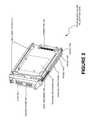
- FIG. 3is a heat transfer view of the storage enclosure of FIG. 1 coupled to a circuit board, according to one embodiment.
- FIG. 4is a perspective view of an array of storage enclosures, according to one embodiment.
- FIG. 5is a perspective view of the circuit board of FIG. 3 , according to one embodiment.
- FIG. 6is a network view of an array with an integrated front motion generator coupled to a data processing system through a network, according to one embodiment.
- FIG. 7is a process flow of forming a series of ridges along opposite faces of a plurality of devices of an array structure, according to one embodiment.
- an apparatuse.g. a storage enclosure 100 as illustrated in FIG. 1
- devicese.g., one or more of a storage mechanism 202 of FIG. 2
- a vented covere.g., a vented cover 102 of FIG. 1
- a channel structuree.g., a channels structure 110 of FIG. 1
- the gasmay modify an operating state of the devices from the undesired temperature to the desired operating temperature (e.g., cool).
- a method of forming an array structureincludes forming a series of ridges (e.g., the ridges 114 of FIG. 1 ) along opposite faces of devices (e.g., hard drives) of the array structure (e.g., an array of storage enclosures 400 of FIG. 1 ), removing a portion of a material of a front cover (e.g., the vented cover 102 of FIG. 1 ) associated with the array structure, and patterning a periphery of a printed circuit board (e.g., midplane, backplane, etc.) of the array structure (e.g., a circuit board 304 of FIG. 4 ) such that the a rear gap formed along the periphery (e.g., gap between adjacent teeth of the saw-tooth pattern) aligns with a channel gap between adjacent ones of the series of ridges (e.g., parallel).
- a printed circuit boarde.g., midplane, backplane, etc.
- a systemin yet another embodiment, includes a network (e.g., local area network, storage area network), a storage array of devices (e.g., hard drives) stacked flush against each other e.g., as illustrated in FIG. 4 ), a data processing system (e.g., a data processing system 602 of FIG. 6 ) coupled to the storage array through the network (e.g., a network 604 of FIG. 6 ), and a motion generator (e.g., fan) positioned in front of the storage array (e.g., a motion generator 118 of FIG. 1 ) to direct a gas through at least one of an upper surface and a lower surface of each of the devices forming the storage array.
- a networke.g., local area network, storage area network
- a storage array of devicese.g., hard drives
- a data processing systeme.g., a data processing system 602 of FIG. 6
- a motion generatore.g., fan
- FIG. 1is a top view of a storage enclosure 100 having a series of ridges 114 A-N (e.g., parallel beams) in a channel structure 110 , according to one embodiment.
- the storage enclosure 100further includes a top cover 112 and a vented cover 102 .
- a connector 106may couple the storage enclosure 100 with other storage enclosures.
- a gase.g., airflow
- the gaspositioned in between the vented cover 102 and the channel structure 110 , may modify the operating state of storage enclosure 100 from an undesired to a desired temperature (e.g.
- any one of the series of ridges 114 A-Nmay transfer the gas though the channel structure 110 to an external location (e.g., rear of the storage enclosure).
- a motion generator 118e.g., a fan
- the storage enclosure 100may be coupled to other storage enclosures to form the array of storage enclosures 400 in FIG. 4 .
- FIG. 2is a bottom view of the storage enclosure 100 of FIG. 1 , according to one embodiment.
- a storage mechanism 202e.g. disk, tape, flash memory, etc.
- FIG. 2illustrates that the heat absorber 108 and/or the channel structure 110 may be formed on both an upper surface and/or a lower surface of the storage enclosure 100 .
- FIG. 3is a heat transfer view of the storage enclosure 100 of FIG. 1 coupled to a circuit board 304 (e.g., backplane, midplane, etc.) through a connector 106 , according to one embodiment.
- a gase.g., an airflow
- the gasmay enter the storage enclosure 100 via the vented cover 102 defined by a series of the vent 104 (e.g., air vents).
- the gascontacts a heat absorber 108 , which absorbs a heat produced by the operation of the storage mechanism 202 .
- the gasmay modify an operating state of the storage enclosure 100 from the undesired temperature to the desired operating temperature (e.g., cool).
- the series of ridges 114 A-N of the channel structure 110may transfer the gas between the heat absorber 108 and the vented cover 102 to an outlet 302 and an external location (e.g., back of the circuit board).
- the circuit board 304may be patterned such that a cavity forms on the periphery and aligns with the series of ridges 114 A-N.
- the outlet 302may be a path from the channel structure 110 to the cavity formed on a periphery of the circuit board 304 and out to an external location.
- FIG. 4is a perspective view of an array of storage enclosures 400 , according to one embodiment.
- the array of storage enclosures 400is formed by at least one storage enclosure 402 having a connector 406 coupled to the circuit board 304 .
- the circuit board 304may be patterned such that a series of projections 404 A-N (saw-tooth pattern) is formed along the periphery.
- a motion generator 418e.g., a fan
- the gasmay enter the storage enclosure 402 via the vented cover 102 .
- the gasmay contact the heat absorber 108 and may modify the operating state of the storage enclosure 402 from an undesired to a desired temperature (e.g., cool).
- the gasmay be transferred from the heat absorber 108 to the circuit board 304 through the series of ridges 114 A N formed on the channel structure 110 .
- the gasmay exit the array of storage enclosures 400 via a gap formed by any two adjacent projections of the series of projections 404 A-N.
- the array of storage enclosures 400may be integrated into the system of FIG. 6 .
- FIG. 5is a perspective view of the circuit board of FIG. 3 , according to one embodiment.
- a circuit board 304e.g., backplane, midplane, etc.
- the circuit board 304further includes a contiguous region between each pair of adjacent connectors of the series of connectors 406 A-N.
- Each pair of adjacent projections of the series of projections 404 A-Ndefines a cavity in order to enable the escape of a gas (e.g., airflow).
- a gase.g., airflow
- FIG. 6is a network view of an array with an integrated front motion generator 600 coupled to a data processing system 602 through a network 604 (e.g., SAN, LAN, WAN, etc.), according to one embodiment.
- the array 600may communicate (e.g., send/receive data (e.g. bits)) with the data processing system 602 through the network 604 .
- the network 604may be the Internet.
- the data processing system 602may receive data stored on the array 600 .
- the data processing system 602may modify and/or translate the data.
- the data processing system 602may send the data through the network 604 to be stored in the array 600 .
- FIG. 7is a process flow of manufacturing an array structure (e.g., array of storage devices).
- a series of ridgesmay be formed along opposite faces of a plurality of devices (e.g., hard drives) of an array structure, according to one embodiment.
- a vente.g., air vent
- a periphery of a printed circuit boarde.g., midplane, backplane, etc.
- a heatmay be produced when an electro-mechanical unit in each of the plurality of devices operates.
- a heat absorbere.g., heat pipe, thermal insulating material, etc.
- a channeled pipecan be bent at a right angle where one portion is positioned along the front cover and the other portion is positioned in between adjacent ones of the series of ridges.
- a printed circuit boardcan be patterned such that the printed circuit board can be positioned along an opposite face relative to the front cover to enable a gas to escape to an external location when channeled from the series of vents to a cavity of the array structure behind the printed circuit board.
- FIG. 7may be enabled and operated using hardware circuitry (e.g., CMOS based logic circuitry), firmware, software and/or any combination of hardware, firmware, and/or software (e.g., embodied in a machine readable medium).
- hardware circuitrye.g., CMOS based logic circuitry
- firmwaree.g., firmware, software and/or any combination of hardware, firmware, and/or software (e.g., embodied in a machine readable medium).
- a ‘storage enclosure’is described herein (e.g., the storage enclosure 100 ), it should be noted that the structure, methods, operations, and forms described herein may be applicable to any structural, electrical, chemical, physical, and/or mechanical environment that requires a thermal controlled condition and/or which may require alteration of a temperature condition (e.g., a gas chamber, a reactor, a generator, a motor, a thermo-chemical core, an electrical and/or mechanical structure generating heat, etc.).
- a temperature conditione.g., a gas chamber, a reactor, a generator, a motor, a thermo-chemical core, an electrical and/or mechanical structure generating heat, etc.
Landscapes
- Engineering & Computer Science (AREA)
- Theoretical Computer Science (AREA)
- Human Computer Interaction (AREA)
- Physics & Mathematics (AREA)
- General Engineering & Computer Science (AREA)
- General Physics & Mathematics (AREA)
- Cooling Or The Like Of Electrical Apparatus (AREA)
Abstract
Description
Claims (18)
Priority Applications (1)
| Application Number | Priority Date | Filing Date | Title |
|---|---|---|---|
| US11/413,853US7826212B2 (en) | 2006-04-27 | 2006-04-27 | Thermal control through a channel structure |
Applications Claiming Priority (1)
| Application Number | Priority Date | Filing Date | Title |
|---|---|---|---|
| US11/413,853US7826212B2 (en) | 2006-04-27 | 2006-04-27 | Thermal control through a channel structure |
Publications (2)
| Publication Number | Publication Date |
|---|---|
| US20080049388A1 US20080049388A1 (en) | 2008-02-28 |
| US7826212B2true US7826212B2 (en) | 2010-11-02 |
Family
ID=39113179
Family Applications (1)
| Application Number | Title | Priority Date | Filing Date |
|---|---|---|---|
| US11/413,853Active2027-06-30US7826212B2 (en) | 2006-04-27 | 2006-04-27 | Thermal control through a channel structure |
Country Status (1)
| Country | Link |
|---|---|
| US (1) | US7826212B2 (en) |
Cited By (7)
| Publication number | Priority date | Publication date | Assignee | Title |
|---|---|---|---|---|
| US20090016010A1 (en)* | 2007-06-13 | 2009-01-15 | Vinson Wade D | Component layout in an enclosure |
| US20120106070A1 (en)* | 2010-11-02 | 2012-05-03 | Trevor Landon | Field serviceable cpu module |
| US20140029184A1 (en)* | 2011-04-05 | 2014-01-30 | Sagem Defense Securite | Assembly for the electronic processing of data with mutualized resources |
| US9052877B2 (en) | 2011-03-16 | 2015-06-09 | Lenovo (Singapore) Pte. Ltd. | Flush faced servers |
| CN109308097A (en)* | 2017-07-27 | 2019-02-05 | 伊姆西Ip控股有限责任公司 | Improved storage device carrier system |
| US10969836B2 (en)* | 2017-10-27 | 2021-04-06 | EMC IP Holding Company LLC | Storage system |
| US20240172385A1 (en)* | 2022-11-21 | 2024-05-23 | Ati Technologies Ulc | Electronics enclosure and expansion card with coanda vent ribs |
Families Citing this family (3)
| Publication number | Priority date | Publication date | Assignee | Title |
|---|---|---|---|---|
| US8111514B2 (en)* | 2006-04-21 | 2012-02-07 | Maxvision Corporation | Removable hard drive module for a computer with improved thermal performance |
| US8724309B2 (en)* | 2011-03-16 | 2014-05-13 | Lenovo (Singapore) Pte. Ltd. | Handle assembly configured for airflow |
| WO2016195755A1 (en)* | 2015-05-06 | 2016-12-08 | Iosafe, Inc. | Optimized disaster resistant housing for an array of computer data storage devices and method of manufacturing |
Citations (45)
| Publication number | Priority date | Publication date | Assignee | Title |
|---|---|---|---|---|
| US4656559A (en)* | 1984-05-10 | 1987-04-07 | Ultima Electronics Ltd. | Holder and heat sink for electronic components |
| US5430609A (en)* | 1993-09-02 | 1995-07-04 | Kikinis; Dan | Microprocessor cooling in a portable computer |
| US5440450A (en)* | 1990-09-14 | 1995-08-08 | Next, Inc. | Housing cooling system |
| US5576932A (en)* | 1995-08-31 | 1996-11-19 | At&T Global Information Solutions Company | Method and apparatus for cooling a heat source |
| US5654873A (en)* | 1996-01-29 | 1997-08-05 | Silicon Graphics, Inc. | Single connector attachment drive sled assembly having light pipe coupled to a rail |
| US5671120A (en)* | 1996-02-07 | 1997-09-23 | Lextron Systems, Inc. | Passively cooled PC heat stack having a heat-conductive structure between a CPU on a motherboard and a heat sink |
| US5712762A (en)* | 1996-03-01 | 1998-01-27 | Compaq Computer Corporation | Computer having a heat sink structure incorporated therein |
| US5828549A (en)* | 1996-10-08 | 1998-10-27 | Dell U.S.A., L.P. | Combination heat sink and air duct for cooling processors with a series air flow |
| US6061237A (en)* | 1998-12-21 | 2000-05-09 | Dell Usa, L.P. | Computer with an improved cooling system and a method for cooling a computer |
| US6069792A (en)* | 1997-09-16 | 2000-05-30 | Nelik; Jacob | Computer component cooling assembly |
| US6088221A (en)* | 1998-06-15 | 2000-07-11 | Compaq Computer Corporation | Hot-pluggable disk drive carrier assembly with no loose parts |
| US6186890B1 (en)* | 1999-06-30 | 2001-02-13 | Emc Corporation | Electronic cabinet door air mixing dam |
| US6315655B1 (en)* | 2000-03-01 | 2001-11-13 | Technology Advancement Group, Inc. | Low profile computer case and computer |
| US6373696B1 (en)* | 1998-06-15 | 2002-04-16 | Compaq Computer Corporation | Hard drive cooling using finned heat sink and thermally conductive interface pad |
| US6384325B1 (en)* | 2000-06-01 | 2002-05-07 | Hewlett-Packard Company | Ventilation port and EMI wave-guide for electronic equipment |
| US20030030978A1 (en)* | 2001-08-10 | 2003-02-13 | Garnett Paul J. | Cooling computer systems |
| US20030183373A1 (en)* | 2002-03-28 | 2003-10-02 | David Sarraf | Video game console cooler |
| US20040001313A1 (en)* | 2002-06-28 | 2004-01-01 | Kabushiki Kaisha Toshiba | Electrode apparatus having a front door covering a front surface of a housing |
| US20040004813A1 (en)* | 1999-10-26 | 2004-01-08 | Giovanni Coglitore | Computer rack cooling system |
| US20040100765A1 (en)* | 2002-11-27 | 2004-05-27 | Internationa Business Machines Corporation | Server blade chassis with airflow bypass damper engaging upon blade removal |
| US20040207983A1 (en)* | 2003-04-18 | 2004-10-21 | Cheng-Yi Lu | Heat dissipation module with twin centrifugal fans |
| US20040252453A1 (en)* | 2003-06-11 | 2004-12-16 | Hewlett-Packard Development Company, L.P. | Computer cooling system and method |
| US20050047087A1 (en)* | 2003-09-02 | 2005-03-03 | Ricardo Espinoza-Ibarra | Fan rotor systems having collapsible fan blades |
| US6867963B2 (en)* | 2002-04-11 | 2005-03-15 | Seagate Technology Llc | Disc drive mounting system including vibration isolator and heat sink |
| US6876547B2 (en)* | 2002-11-14 | 2005-04-05 | Dell Products L.P. | Hard drive carrier |
| US20050168945A1 (en)* | 2003-12-29 | 2005-08-04 | Giovanni Coglitore | Computer rack cooling system with variable airflow impedance |
| US6927976B1 (en)* | 2004-01-15 | 2005-08-09 | Hewlett-Packard Development Company, L.P. | Air baffle for managing cooling air re-circulation in an electronic system |
| US20050254210A1 (en)* | 2004-05-14 | 2005-11-17 | Grady John R | Fan tray for electronics enclosure |
| US20050259395A1 (en)* | 2003-07-31 | 2005-11-24 | Espinoza-Lbarra Ricardo | System fan management based on system loading options for a system having replaceable electronics modules |
| US20050280986A1 (en)* | 2004-05-07 | 2005-12-22 | Giovanni Coglitore | Directional fan assembly |
| US20060023422A1 (en)* | 2004-01-28 | 2006-02-02 | Shum Kent N | Modular electronic enclosure with cooling design |
| US20060039108A1 (en)* | 2004-08-20 | 2006-02-23 | Takashi Chikusa | Disk array device |
| US7011147B1 (en)* | 2004-11-17 | 2006-03-14 | Chung-Tsai Hung | Heat pipe type circular radiator with sector cooling fins |
| US20060061955A1 (en)* | 2004-09-21 | 2006-03-23 | Imblum Raymond W | Disk drive support system |
| US20060148398A1 (en)* | 2004-12-20 | 2006-07-06 | Mark Ruch | Air vent and method |
| US20060227505A1 (en)* | 2005-04-06 | 2006-10-12 | Kenichi Miyamoto | Air flow distribution adjusting mechanism for disk array apparatus |
| US20060232930A1 (en)* | 2005-04-13 | 2006-10-19 | Dell Products L.P. | Method and apparatus for cooling an information handling system |
| US7158380B2 (en)* | 2005-03-25 | 2007-01-02 | Scientific-Atlanta, Inc. | Heatsink for digital video recorder |
| US7206201B2 (en)* | 1999-04-23 | 2007-04-17 | Steinbeck Cannery Llc | Memory storage device docking adapter having a laterally mounted fan |
| USD541286S1 (en)* | 2005-08-03 | 2007-04-24 | Hewlett-Packard Development Company, L.P. | Computer having release handles |
| US7227744B2 (en)* | 2003-04-25 | 2007-06-05 | Teac Corporation | Data recording device and memory cartridge of data recording device |
| US7269006B2 (en)* | 2004-12-06 | 2007-09-11 | Hitachi, Ltd. | Storage device, and storage part and dummy unit for storage device |
| US20080037218A1 (en)* | 2006-03-24 | 2008-02-14 | Sharma Viswa M | Modular chassis providing scalable mechanical, electrical and environmental functionality for MicroTCA and advanced TCA boards |
| US7331379B2 (en)* | 2005-07-18 | 2008-02-19 | Fu Zhun Precision Industry (Shen Zhen) Co., Ltd. | Heat dissipation device with heat pipe |
| US7420805B2 (en)* | 2002-05-31 | 2008-09-02 | Verari Systems, Inc. | Method and apparatus for rack mounting computer components |
- 2006
- 2006-04-27USUS11/413,853patent/US7826212B2/enactiveActive
Patent Citations (45)
| Publication number | Priority date | Publication date | Assignee | Title |
|---|---|---|---|---|
| US4656559A (en)* | 1984-05-10 | 1987-04-07 | Ultima Electronics Ltd. | Holder and heat sink for electronic components |
| US5440450A (en)* | 1990-09-14 | 1995-08-08 | Next, Inc. | Housing cooling system |
| US5430609A (en)* | 1993-09-02 | 1995-07-04 | Kikinis; Dan | Microprocessor cooling in a portable computer |
| US5576932A (en)* | 1995-08-31 | 1996-11-19 | At&T Global Information Solutions Company | Method and apparatus for cooling a heat source |
| US5654873A (en)* | 1996-01-29 | 1997-08-05 | Silicon Graphics, Inc. | Single connector attachment drive sled assembly having light pipe coupled to a rail |
| US5671120A (en)* | 1996-02-07 | 1997-09-23 | Lextron Systems, Inc. | Passively cooled PC heat stack having a heat-conductive structure between a CPU on a motherboard and a heat sink |
| US5712762A (en)* | 1996-03-01 | 1998-01-27 | Compaq Computer Corporation | Computer having a heat sink structure incorporated therein |
| US5828549A (en)* | 1996-10-08 | 1998-10-27 | Dell U.S.A., L.P. | Combination heat sink and air duct for cooling processors with a series air flow |
| US6069792A (en)* | 1997-09-16 | 2000-05-30 | Nelik; Jacob | Computer component cooling assembly |
| US6373696B1 (en)* | 1998-06-15 | 2002-04-16 | Compaq Computer Corporation | Hard drive cooling using finned heat sink and thermally conductive interface pad |
| US6088221A (en)* | 1998-06-15 | 2000-07-11 | Compaq Computer Corporation | Hot-pluggable disk drive carrier assembly with no loose parts |
| US6061237A (en)* | 1998-12-21 | 2000-05-09 | Dell Usa, L.P. | Computer with an improved cooling system and a method for cooling a computer |
| US7206201B2 (en)* | 1999-04-23 | 2007-04-17 | Steinbeck Cannery Llc | Memory storage device docking adapter having a laterally mounted fan |
| US6186890B1 (en)* | 1999-06-30 | 2001-02-13 | Emc Corporation | Electronic cabinet door air mixing dam |
| US20040004813A1 (en)* | 1999-10-26 | 2004-01-08 | Giovanni Coglitore | Computer rack cooling system |
| US6315655B1 (en)* | 2000-03-01 | 2001-11-13 | Technology Advancement Group, Inc. | Low profile computer case and computer |
| US6384325B1 (en)* | 2000-06-01 | 2002-05-07 | Hewlett-Packard Company | Ventilation port and EMI wave-guide for electronic equipment |
| US20030030978A1 (en)* | 2001-08-10 | 2003-02-13 | Garnett Paul J. | Cooling computer systems |
| US20030183373A1 (en)* | 2002-03-28 | 2003-10-02 | David Sarraf | Video game console cooler |
| US6867963B2 (en)* | 2002-04-11 | 2005-03-15 | Seagate Technology Llc | Disc drive mounting system including vibration isolator and heat sink |
| US7420805B2 (en)* | 2002-05-31 | 2008-09-02 | Verari Systems, Inc. | Method and apparatus for rack mounting computer components |
| US20040001313A1 (en)* | 2002-06-28 | 2004-01-01 | Kabushiki Kaisha Toshiba | Electrode apparatus having a front door covering a front surface of a housing |
| US6876547B2 (en)* | 2002-11-14 | 2005-04-05 | Dell Products L.P. | Hard drive carrier |
| US20040100765A1 (en)* | 2002-11-27 | 2004-05-27 | Internationa Business Machines Corporation | Server blade chassis with airflow bypass damper engaging upon blade removal |
| US20040207983A1 (en)* | 2003-04-18 | 2004-10-21 | Cheng-Yi Lu | Heat dissipation module with twin centrifugal fans |
| US7227744B2 (en)* | 2003-04-25 | 2007-06-05 | Teac Corporation | Data recording device and memory cartridge of data recording device |
| US20040252453A1 (en)* | 2003-06-11 | 2004-12-16 | Hewlett-Packard Development Company, L.P. | Computer cooling system and method |
| US20050259395A1 (en)* | 2003-07-31 | 2005-11-24 | Espinoza-Lbarra Ricardo | System fan management based on system loading options for a system having replaceable electronics modules |
| US20050047087A1 (en)* | 2003-09-02 | 2005-03-03 | Ricardo Espinoza-Ibarra | Fan rotor systems having collapsible fan blades |
| US20050168945A1 (en)* | 2003-12-29 | 2005-08-04 | Giovanni Coglitore | Computer rack cooling system with variable airflow impedance |
| US6927976B1 (en)* | 2004-01-15 | 2005-08-09 | Hewlett-Packard Development Company, L.P. | Air baffle for managing cooling air re-circulation in an electronic system |
| US20060023422A1 (en)* | 2004-01-28 | 2006-02-02 | Shum Kent N | Modular electronic enclosure with cooling design |
| US20050280986A1 (en)* | 2004-05-07 | 2005-12-22 | Giovanni Coglitore | Directional fan assembly |
| US20050254210A1 (en)* | 2004-05-14 | 2005-11-17 | Grady John R | Fan tray for electronics enclosure |
| US20060039108A1 (en)* | 2004-08-20 | 2006-02-23 | Takashi Chikusa | Disk array device |
| US20060061955A1 (en)* | 2004-09-21 | 2006-03-23 | Imblum Raymond W | Disk drive support system |
| US7011147B1 (en)* | 2004-11-17 | 2006-03-14 | Chung-Tsai Hung | Heat pipe type circular radiator with sector cooling fins |
| US7269006B2 (en)* | 2004-12-06 | 2007-09-11 | Hitachi, Ltd. | Storage device, and storage part and dummy unit for storage device |
| US20060148398A1 (en)* | 2004-12-20 | 2006-07-06 | Mark Ruch | Air vent and method |
| US7158380B2 (en)* | 2005-03-25 | 2007-01-02 | Scientific-Atlanta, Inc. | Heatsink for digital video recorder |
| US20060227505A1 (en)* | 2005-04-06 | 2006-10-12 | Kenichi Miyamoto | Air flow distribution adjusting mechanism for disk array apparatus |
| US20060232930A1 (en)* | 2005-04-13 | 2006-10-19 | Dell Products L.P. | Method and apparatus for cooling an information handling system |
| US7331379B2 (en)* | 2005-07-18 | 2008-02-19 | Fu Zhun Precision Industry (Shen Zhen) Co., Ltd. | Heat dissipation device with heat pipe |
| USD541286S1 (en)* | 2005-08-03 | 2007-04-24 | Hewlett-Packard Development Company, L.P. | Computer having release handles |
| US20080037218A1 (en)* | 2006-03-24 | 2008-02-14 | Sharma Viswa M | Modular chassis providing scalable mechanical, electrical and environmental functionality for MicroTCA and advanced TCA boards |
Cited By (12)
| Publication number | Priority date | Publication date | Assignee | Title |
|---|---|---|---|---|
| US20090016010A1 (en)* | 2007-06-13 | 2009-01-15 | Vinson Wade D | Component layout in an enclosure |
| US8144458B2 (en)* | 2007-06-13 | 2012-03-27 | Hewlett-Packard Development Company, L.P. | Component layout in an enclosure |
| US20120106070A1 (en)* | 2010-11-02 | 2012-05-03 | Trevor Landon | Field serviceable cpu module |
| US8537540B2 (en)* | 2010-11-02 | 2013-09-17 | Technology Advancement Group, Inc. | Field serviceable CPU module |
| US9052877B2 (en) | 2011-03-16 | 2015-06-09 | Lenovo (Singapore) Pte. Ltd. | Flush faced servers |
| US20140029184A1 (en)* | 2011-04-05 | 2014-01-30 | Sagem Defense Securite | Assembly for the electronic processing of data with mutualized resources |
| US9426913B2 (en)* | 2011-04-05 | 2016-08-23 | Sagem Defense Securite | Assembly for the electronic processing of data with mutualized resources |
| CN109308097A (en)* | 2017-07-27 | 2019-02-05 | 伊姆西Ip控股有限责任公司 | Improved storage device carrier system |
| US11076497B2 (en) | 2017-07-27 | 2021-07-27 | EMC IP Holding Company, LLC | Storage device carrier system |
| CN109308097B (en)* | 2017-07-27 | 2021-10-15 | 伊姆西Ip控股有限责任公司 | Improved storage device tray system |
| US10969836B2 (en)* | 2017-10-27 | 2021-04-06 | EMC IP Holding Company LLC | Storage system |
| US20240172385A1 (en)* | 2022-11-21 | 2024-05-23 | Ati Technologies Ulc | Electronics enclosure and expansion card with coanda vent ribs |
Also Published As
| Publication number | Publication date |
|---|---|
| US20080049388A1 (en) | 2008-02-28 |
Similar Documents
| Publication | Publication Date | Title |
|---|---|---|
| US7826212B2 (en) | Thermal control through a channel structure | |
| JP4108472B2 (en) | Disk array unit | |
| JP5243614B2 (en) | Storage device, storage controller of storage device, and housing for storage controller | |
| JP5056987B2 (en) | Electronic equipment | |
| JP4335760B2 (en) | Rack mount storage unit and rack mount disk array device | |
| US7715188B2 (en) | Disk array apparatus for providing equalized cooling | |
| US7522413B2 (en) | Heat dissipating system | |
| CN1945022B (en) | Electronic equipment | |
| US8089763B2 (en) | Heat-dissipating assembly for server | |
| JP5392403B2 (en) | Case, board module and air cooling structure | |
| TW201221035A (en) | Server rack | |
| WO2012077186A1 (en) | Storage device, and partitiion plate in storage device | |
| JP2008016137A (en) | Disk array device | |
| US8164900B2 (en) | Enclosure of electronic device | |
| TW200825692A (en) | Computer system cooling system | |
| US20120155009A1 (en) | Server with fan module | |
| JPH0661390A (en) | Semiconductor integrated circuit element cooling structure, semiconductor integrated circuit element cooling substrate used for the same, and computer semiconductor integrated circuit element cooling structure using the same | |
| JP2007188599A (en) | Electronic device | |
| US20070098281A1 (en) | Damping rotational vibration in a multi-drive tray | |
| JP2002237178A (en) | Disk array device | |
| JP5342363B2 (en) | Control device mounting structure | |
| JP5792427B2 (en) | Disk array device | |
| JP6546640B2 (en) | Chassis | |
| JP2008090772A (en) | Information processing device | |
| JP2007183735A (en) | Electronic equipment |
Legal Events
| Date | Code | Title | Description |
|---|---|---|---|
| AS | Assignment | Owner name:LSI LOGIC CORPORATION, CALIFORNIA Free format text:ASSIGNMENT OF ASSIGNORS INTEREST;ASSIGNORS:SHOGAN, GREGORY;DUNHAM, JOHN MAYNARD;REEL/FRAME:017849/0390 Effective date:20060426 | |
| FEPP | Fee payment procedure | Free format text:PAYOR NUMBER ASSIGNED (ORIGINAL EVENT CODE: ASPN); ENTITY STATUS OF PATENT OWNER: LARGE ENTITY | |
| STCF | Information on status: patent grant | Free format text:PATENTED CASE | |
| AS | Assignment | Owner name:NETAPP, INC., CALIFORNIA Free format text:ASSIGNMENT OF ASSIGNORS INTEREST;ASSIGNOR:LSI LOGIC CORPORATION;REEL/FRAME:026661/0205 Effective date:20110506 | |
| FPAY | Fee payment | Year of fee payment:4 | |
| MAFP | Maintenance fee payment | Free format text:PAYMENT OF MAINTENANCE FEE, 8TH YEAR, LARGE ENTITY (ORIGINAL EVENT CODE: M1552) Year of fee payment:8 | |
| MAFP | Maintenance fee payment | Free format text:PAYMENT OF MAINTENANCE FEE, 12TH YEAR, LARGE ENTITY (ORIGINAL EVENT CODE: M1553); ENTITY STATUS OF PATENT OWNER: LARGE ENTITY Year of fee payment:12 |