US7825867B2 - Methods and systems of changing antenna polarization - Google Patents
Methods and systems of changing antenna polarizationDownload PDFInfo
- Publication number
- US7825867B2 US7825867B2US11/740,393US74039307AUS7825867B2US 7825867 B2US7825867 B2US 7825867B2US 74039307 AUS74039307 AUS 74039307AUS 7825867 B2US7825867 B2US 7825867B2
- Authority
- US
- United States
- Prior art keywords
- antenna
- feed point
- polarization
- rfid
- tag
- Prior art date
- Legal status (The legal status is an assumption and is not a legal conclusion. Google has not performed a legal analysis and makes no representation as to the accuracy of the status listed.)
- Expired - Fee Related, expires
Links
- 230000010287polarizationEffects0.000titleclaimsabstractdescription134
- 238000000034methodMethods0.000titleabstractdescription11
- 238000004891communicationMethods0.000claimsabstractdescription17
- 230000005670electromagnetic radiationEffects0.000claimsdescription17
- 230000007717exclusionEffects0.000claimsdescription7
- XUIMIQQOPSSXEZ-UHFFFAOYSA-NSiliconChemical compound[Si]XUIMIQQOPSSXEZ-UHFFFAOYSA-N0.000claimsdescription6
- 239000010703siliconSubstances0.000claimsdescription6
- 229910052710siliconInorganic materials0.000claimsdescription6
- 239000003989dielectric materialSubstances0.000claimsdescription5
- 230000005669field effectEffects0.000claimsdescription3
- 230000008878couplingEffects0.000description6
- 238000010168coupling processMethods0.000description6
- 238000005859coupling reactionMethods0.000description6
- 238000010586diagramMethods0.000description6
- 230000005540biological transmissionEffects0.000description4
- 238000004519manufacturing processMethods0.000description4
- 239000007787solidSubstances0.000description4
- 230000005684electric fieldEffects0.000description3
- 230000007246mechanismEffects0.000description3
- 239000004065semiconductorSubstances0.000description3
- 238000013461designMethods0.000description2
- 239000000463materialSubstances0.000description2
- 239000007769metal materialSubstances0.000description2
- 229910044991metal oxideInorganic materials0.000description2
- 150000004706metal oxidesChemical class0.000description2
- 238000012986modificationMethods0.000description2
- 230000004048modificationEffects0.000description2
- 239000004033plasticSubstances0.000description2
- RYGMFSIKBFXOCR-UHFFFAOYSA-NCopperChemical compound[Cu]RYGMFSIKBFXOCR-UHFFFAOYSA-N0.000description1
- 238000010276constructionMethods0.000description1
- 229910052802copperInorganic materials0.000description1
- 239000010949copperSubstances0.000description1
- 238000012937correctionMethods0.000description1
- 230000000694effectsEffects0.000description1
- 238000005516engineering processMethods0.000description1
- 239000000446fuelSubstances0.000description1
- 239000000523sampleSubstances0.000description1
- 238000011144upstream manufacturingMethods0.000description1
Images
Classifications
- H—ELECTRICITY
- H01—ELECTRIC ELEMENTS
- H01Q—ANTENNAS, i.e. RADIO AERIALS
- H01Q21/00—Antenna arrays or systems
- H01Q21/24—Combinations of antenna units polarised in different directions for transmitting or receiving circularly and elliptically polarised waves or waves linearly polarised in any direction
- H—ELECTRICITY
- H01—ELECTRIC ELEMENTS
- H01Q—ANTENNAS, i.e. RADIO AERIALS
- H01Q1/00—Details of, or arrangements associated with, antennas
- H01Q1/12—Supports; Mounting means
- H01Q1/22—Supports; Mounting means by structural association with other equipment or articles
- H01Q1/2208—Supports; Mounting means by structural association with other equipment or articles associated with components used in interrogation type services, i.e. in systems for information exchange between an interrogator/reader and a tag/transponder, e.g. in Radio Frequency Identification [RFID] systems
- H01Q1/2216—Supports; Mounting means by structural association with other equipment or articles associated with components used in interrogation type services, i.e. in systems for information exchange between an interrogator/reader and a tag/transponder, e.g. in Radio Frequency Identification [RFID] systems used in interrogator/reader equipment
- H—ELECTRICITY
- H01—ELECTRIC ELEMENTS
- H01Q—ANTENNAS, i.e. RADIO AERIALS
- H01Q1/00—Details of, or arrangements associated with, antennas
- H01Q1/12—Supports; Mounting means
- H01Q1/22—Supports; Mounting means by structural association with other equipment or articles
- H01Q1/2208—Supports; Mounting means by structural association with other equipment or articles associated with components used in interrogation type services, i.e. in systems for information exchange between an interrogator/reader and a tag/transponder, e.g. in Radio Frequency Identification [RFID] systems
- H01Q1/2225—Supports; Mounting means by structural association with other equipment or articles associated with components used in interrogation type services, i.e. in systems for information exchange between an interrogator/reader and a tag/transponder, e.g. in Radio Frequency Identification [RFID] systems used in active tags, i.e. provided with its own power source or in passive tags, i.e. deriving power from RF signal
- H—ELECTRICITY
- H01—ELECTRIC ELEMENTS
- H01Q—ANTENNAS, i.e. RADIO AERIALS
- H01Q9/00—Electrically-short antennas having dimensions not more than twice the operating wavelength and consisting of conductive active radiating elements
- H01Q9/04—Resonant antennas
- H01Q9/0407—Substantially flat resonant element parallel to ground plane, e.g. patch antenna
- H01Q9/0421—Substantially flat resonant element parallel to ground plane, e.g. patch antenna with a shorting wall or a shorting pin at one end of the element
Definitions
- At least some of the various embodimentsare directed to systems and methods to selectively radiate and/or receive electromagnetic waves having varying electric field polarizations.
- radiating or receiving electromagnetic waves with varying polarizationdictates having multiple antennas, with each antenna configured to transmit an electromagnetic wave with a particular polarization (e.g. multiple dipole antennas in different physical orientations, multiple patch antennas in different physical orientations).
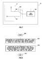
- FIG. 1shows a radio frequency identification (RFID) system in accordance with at least some embodiments
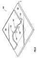
- FIG. 2shows a more detailed system in accordance with at least some embodiments
- FIG. 3shows a patch antenna with multiple feed points in accordance with at least some embodiments
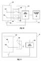
- FIG. 4shows an electrical block diagram of a system in accordance with at least some embodiments
- FIG. 5shows a patch antenna in accordance with other embodiments
- FIG. 6shows an electrical block diagram of a system in accordance with other embodiments
- FIG. 7shows a RFID tag in accordance with at least some embodiments
- FIG. 8shows a method in accordance with at least some embodiments
- FIG. 9shows a patch antenna with ground points in accordance with at least some embodiments.
- FIG. 10shows an electrical block diagram of a system in accordance with at least some embodiments.
- FIG. 11shows a RFID tag in accordance with at least some embodiments.
- Coupleor “couples” is intended to mean either an indirect or direct connection. Thus, if a first device couples to a second device, that connection may be through a direct connection or through an indirect connection via other intermediate devices and connections.
- systemmeans “one or more components” combined together. Thus, a system can comprise an “entire system,” “subsystems” within the system, a radio frequency identification (RFID) tag, a RFID reader, or any other device comprising one or more components.
- RFIDradio frequency identification
- RFIDradio frequency identification
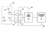
- FIG. 1illustrates a system 1000 in accordance with at least some embodiments.
- system 1000comprises an electronic system 10 coupled to a RFID reader 12 .
- electronic system 10comprises a computer system.
- the RFID reader 12communicates with one or more RFID tags 16 A- 16 C proximate to the RFID reader (i.e., within communication range).
- the RFID reader 12may be equivalently referred as an interrogator.
- the RFID reader 12passes data obtained from the various RFID tags 16 to the electronic system 10 , which performs any suitable function.
- the electronic system 10may allow access to a building or parking garage, note the entrance of an employee to a work location, direct a parcel identified by the RFID tag 16 down a particular conveyor system, or display an advertisement customized or targeted to the person identified by the RFID tag 16 .
- RFID tagsmay be active tags, meaning each RFID tag comprises its own internal battery. Using power from the internal battery, an active RFID tag monitors for interrogating signals from the RFID reader 12 . When an interrogating signal is sensed, a response comprising a data or identification value is transmitted by the active RFID tag using power from its internal battery.
- a semi-active tagmay likewise have its own internal battery, but a semi-active tag stays dormant most of the time. When an antenna of a semi-active tag receives an interrogating signal, the power received is used to wake or activate the semi-active tag, and a response comprising an identification value is sent by the semi-active RFID tag using power from its internal battery.
- a third type of RFID tagis a passive tag, which, unlike active and semi-active RFID tags, has no internal battery.
- the antenna of the passive RFID tagreceives an interrogating signal, and the power extracted from the received interrogating signal is used to power the tag.
- the passive RFID tagmay accept a command, send a response comprising a data or identification value, or both; however, the value is sent in the form of backscattered electromagnetic waves to the RFID reader 12 antenna 14 from the antenna 17 of the RFID tag 16 .
- the RFID reader 12 and antenna 14continue to transmit power after the RFID tag is awake. While the RFID reader 12 transmits, the antenna 17 of the RFID tag is selectively tuned and de-tuned with respect to the carrier frequency.
- the terms transmitting and transmissioninclude not only sending from an antenna using internally sourced power, but also sending in the form of backscattered signals.
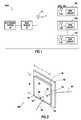
- FIG. 2shows a more detailed system 2000 in accordance with some embodiments.
- system 2000shows an object 20 on a conveyor system 22 , and in some embodiments with the object 20 selectively moving in the direction indicated by arrow 14 .
- Conveyor system 22is merely illustrative of any situation where an object 20 may be in a plurality of positions relative to a system for reading the RFID tag 16 , such as reading by RFID reader 12 .
- the object 20 and conveyor system 22are illustrative of wafer boats in semiconductor manufacturing production line, luggage in an automated luggage handling system, parcels in an automated sorting facility, consumer goods in a shopping cart, or participants in a war game.
- the object 20has an associated RFID tag 16 , which as illustrated is visible both from in front of the object 20 , and from behind the object 20 .
- the RFID tag 16uses a dual-sided patch antenna, such as described in co-pending and commonly assigned application Ser. No. 11/691,822 titled “Multi-Antenna Element Systems and Related Methods,” incorporated by reference herein as if reproduced in full below.
- any suitable antennamay be used on the RFID tag 16 .
- one antenna element 26 of the RFID tag 16is visible, with the antenna element 26 having a feed point 28 .
- a second antenna element(not visible in FIG. 2 ), may also be present, and the second antenna element likewise has a feed point.
- the system 2000further comprises a reading antenna 24 positioned downstream of the direction of travel of the object 20 .
- the reading antenna 24may be placed at any suitable position (e.g. upstream of the path of travel), or there may be reading antennas at any position relative to the path of travel.
- Electronic system 10 and RFID reader 12couple to the reading antenna 24 , and the RFID reader 12 reads the RFID tag 16 by way of an antenna element of the RFID tag 16 (e.g., antenna element 26 ).
- the RFID reader 12 and/or electronic system 10determine certain physical characteristics of the RFID tag 16 and attached object 20 .
- the RFID reader 12 and/or electronic system 10may be implemented in a system which determines which face or side of the object 20 (e.g., face 30 or 32 ) is exposed to the reading antenna 24 .
- the RFID reader 12 and/or electronic system 10may be implemented in a system which determines the rotational orientation of the object 20 (e.g. which side 34 , 36 faces upwards).
- These and possibly other physical characteristics of the RFID tag 16 and attached object 20may be determined by polarization of electromagnetic waves or signals transmitted by the RFID tag 16 .
- each face 30 , 32 of the object 20is associated with a particular polarization of electromagnetic signal transmitted from the RFID tag 16 (or possibly multiple RFID tags, one each on each face of the object 20 ).
- the RFID tag 16responds with an electromagnetic signal having a particular polarization, and in these embodiments the polarization identifies the which face of the object 20 is exposed to or facing the reading antenna 24 .
- the polarization of an antenna of the RFID tag 16is aligned with a rotational orientation of the object 20 (e.g. vertical polarization aligned with upright orientation of the object 20 ).
- the RFID tag 16When interrogated by the reading antenna 24 , the RFID tag 16 responds with an electromagnetic signal having a particular polarization, and in these illustrative embodiments the polarization identifies the rotational orientation of the object 20 (e.g. a horizontally polarized electromagnetic signal from the RFID tag 16 indicates the object 20 is laying on its side).
- FIG. 3illustrates a patch antenna 300 in accordance with at least some embodiments.
- patch antenna 300comprises a radiative patch or antenna element 40 .
- the antenna element 40comprises a sheet of metallic material (e.g. copper) that defines a perimeter.
- the antenna element 40is in the form of a square or rectangle.
- the length (“L” in the figure) and width (“W” in the figure) of the illustrative antenna element 40is dictated by the wavelength of the radio frequency signal that will be driven to the antenna element 40 (or that will be received by the antenna element 40 ). More particularly, the length and width of the antenna element 40 are each an integer ratio of the wavelength of the signal to be transmitted (or received). For example, the length L and width W may be approximately half the wavelength ( ⁇ /2) or a quarter of the wavelength ( ⁇ /4).
- the patch antenna 300also comprises a ground plane or ground element 42 .
- the antenna element 40 and the ground element 42each define a plane, and those planes are substantially parallel in at least some embodiments.
- the ground element 42 length and widthare shown to be greater than the length and width of the antenna element 40 ; however, the ground element length and width may be smaller in other embodiments.
- a dielectric material 44e.g., printed circuit board material, silicon, plastic
- Radio frequency signalsare driven to the antenna element 40 by way of probe feeds or feed points (i.e., the locations where the radio frequency signals couple to the antenna element 40 ), such as feed point 46 or feed point 48 .
- the feed pointsare shown (in dashed lines) to extend through the antenna element 40 , dielectric 44 and ground plane 42 , and then to couple to respective leads 50 (for feed point 46 ) and 52 (for the feed point 48 ).
- the leads 50 , 52may extend to their respective feed points through the dielectric material 44 , but not through the ground element 42 (i.e., the leads emerge from the dielectric material). In either case, the feed points are electrically isolated from the ground element 42 .
- illustrative feed point 46resides within the perimeter defined by the antenna element 40 , and placement of the feed point is selected based on several criteria.
- One such criterionis the impedance seen by a radio frequency source that drives the antenna element 40 .
- shifting the feed point 46 toward the center of the antenna element 40 along its length (“L” in the figure)tends to lower the impedance seen by the radio frequency source, while shifting along the length towards an edge (e.g., edge 54 ) tends to increase impedance seen by the radio frequency source.
- the placement of the feed point 46also controls polarity of the electromagnetic wave or signal created.
- illustrative feed point 46creates an electromagnetic signal with a particular electric field polarization (e.g. horizontal polarization (along the length L)). Shifting the feed point toward a corner (e.g. corner 56 ) creates a different polarization (e.g. circular polarization).
- a particular electric field polarizatione.g. horizontal polarization (along the length L)
- Shifting the feed point toward a cornere.g. corner 56
- a different polarizatione.g. circular polarization
- Illustrative feed point 48also resides within the perimeter defined by the antenna element 40 . Shifting the illustrative feed point 48 toward the center of the antenna element 40 along its width (“W” in the figure) tends to lower the impedance seen by the radio frequency source, while shifting along the width towards an edge (e.g. edge 58 ) tends to increase impedance seen by the radio frequency source. Moreover, illustrative feed point 48 as shown creates an electromagnetic signal with a particular polarization (e.g. a vertical polarization (along the length W)). Shifting the feed point toward a corner (e.g. corner 60 ) creates an electromagnetic wave having a different polarization (e.g. circularly polarized). Thus, the feed points are internal to the length and width to meet these, and possibly other, design criteria.
- Wwidth
- an edgee.g. edge 58
- illustrative feed point 48as shown creates an electromagnetic signal with a particular polarization (e.g. a
- the illustrative patch antenna 300may be used as the reading antenna 24 .
- a single antenna 24can be used to radiate electromagnetic waves of varying polarization (e.g. to radiate interrogating signals to an RFID tag), and likewise to receive electromagnetic waves of varying polarization (e.g. receive responses from RFID tags).
- FIG. 4shows an electrical block diagram that illustrates coupling of the RFID reader 12 to the reading antenna 24 in accordance with at least some embodiments.
- reading antenna 24is illustrated as two antennas 70 and 72 .
- Antenna 70is schematically shown upright to signify polarization associated with a first feed point (e.g. feed point 48 which, when used, may transmit or receive electromagnetic signals having an illustrative vertical polarization).
- antenna 72is shown prone to signify polarization associated with a second feed point (e.g. feed point 46 which, when used, may transmit or receive electromagnetic signals having an illustrative horizontal polarization).
- the RFID reader 12couples to each feed point through a switch assembly 75 , which is illustrated as individual single-pole single-throw switches 74 and 76 .
- the switch assembly 75couples the RFID reader 12 to the feed points of the patch antenna 24 in a mutually exclusive manner (i.e., one and only one at a time)
- the switch assembly 75could be a single-pole double-throw switch.
- the RFID reader 12 and/or electronic system 10are configured to transmit electromagnetic signals having an illustrative vertical polarization.
- switch 74is closed or made conducting, while switch 76 is opened or made non-conducting.
- the RFID reader 12generates an antenna feed signal, and the antenna feed signal is applied to the first feed point 48 through the switch 74 .
- the reading antenna 24radiates an electromagnetic wave having the illustrative vertical polarization.
- the antenna feed signal generated by the RFID reader 12is applied to feed point 48 to the exclusion of other feed points (i.e., the antenna feed signal is not applied to feed point 46 in the illustration of FIG. 4 ).
- the RFID reader 12 and/or electronic system 10are configured to receive vertically polarized electromagnetic signals.
- switch 74is again closed or made conducting, while switch 76 is again opened or made non-conducting.
- the reading antenna 24produces an electrical signal that moves between the feed point 48 and the RFID reader 12 , the electrical signal predominantly proportional to vertically polarized electromagnetic radiation incident upon the reading antenna 24 .
- the RFID reader 12 and/or electronic system 10are configured to transmit electromagnetic signals having an illustrative horizontal polarization.
- switch 76is closed or made conducting, while switch 74 is opened or made non-conducting.
- the RFID reader 12generates an antenna feed signal, and the antenna feed signal is applied to the feed point 46 through the switch 76 .
- the reading antennaradiates an electromagnetic wave having the illustrative horizontal polarization.
- the antenna feed signal generated by the RFID reader 12is applied to feed point 46 to the exclusion of other feed points (i.e., the antenna feed signal is not applied to feed point 48 in the illustration of FIG. 4 ).
- the switch assembly 75 used to selectively to couple the RFID reader 12 to the reading antenna 24may take many forms.
- one or more mechanical switchesare used, where the mechanic switches are closed (made conducting) or opened (made non-conducting) by physical manipulation of the switches (e.g. knife blade switches).
- the switch assembly 75is one ore more electrically controlled switches. Examples of electrically controlled switches that may be used are solenoid operated relays, or solid state switches (e.g., transistors, silicon controlled rectifier pairs).
- transistorse.g., transistors, silicon controlled rectifier pairs.
- MOSFETsmetal oxide semiconductor field effect transistors
- the device that controls the electrically controlled switches 74 and 76may vary as well.
- the RFID reader 12controls the switch positions of the illustrative switches 74 and 76 , as shown by dashed line 78 in FIG. 4 .
- the electronic system 10controls the switch positions of the illustrative switches 74 and 76 , as shown by dashed lines 80 in FIG. 4 .
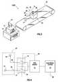
- FIG. 5shows a patch antenna 500 in accordance with further embodiments.
- patch antenna 500comprises an antenna element 40 and ground element 42 separated by dielectric 44 .
- Patch antenna 500further comprises an illustrative three feed points 90 , 92 and 94 .
- feed point 92is used alone during transmission, the patch antenna 500 creates an electromagnetic wave with a particular polarization (e.g. horizontal polarization).
- the patch antenna 500When feed point 94 is used alone during transmission, the patch antenna 500 creates an electromagnetic wave with a different polarization (e.g. vertical polarization). When feed points 90 and 92 are used together (to the exclusion of feed point 94 ), the patch antenna 500 creates an electromagnetic wave with yet another polarization (e.g., circular polarization). Likewise, when feed points 90 and 94 are used together (to the exclusion of feed point 92 ), the patch antenna 500 creates an electromagnetic wave with yet still another polarization (e.g. circular polarization, but where the rotational orientation of the polarization is different than that produced when feed points 90 and 92 are used). Thus, a system (such as system 2000 of FIG. 2 ) may selectively use any polarization that may be transmitted or received by a reading antenna 24 .
- a systemsuch as system 2000 of FIG. 2
- FIG. 6shows an electrical block diagram that illustrates coupling of the RFID reader 12 to the reading antenna 24 in embodiments where feed points are used in groups.
- reading antenna 24is illustrated in this figure as three antennas 96 , 98 and 100 (e.g. associated with feed points 94 , 90 and 92 respectively of patch antenna 500 of FIG. 5 ).
- the RFID reader 12couples to the reading antenna through a switch assembly 101 , which is illustrated as individual single-pole single-throw switches 102 and 104 .
- the switch assembly 101couples the RFID reader 12 to the feed point 94 or a feed point group (comprising feed points 90 and 92 ) mutually exclusively, the switch assembly 101 could be a single-pole double-throw switch.
- FIG. 1shows an electrical block diagram that illustrates coupling of the RFID reader 12 to the reading antenna 24 in embodiments where feed points are used in groups.
- reading antenna 24is illustrated in this figure as three antennas 96 , 98 and 100 (e.g. associated with feed points 94 , 90 and
- the RFID reader 12couples to feed point 94 through switch 102 , and the RFID reader 12 couples to feed points 90 and 92 through switch 104 .
- the switches 102 and 104may be of the same type and construction as those discussed with respect to the switch assembly 75 of FIG. 4 .
- a single feed point or group of feed pointsmay be used to radiate and receive electromagnetic waves of particular polarization, with the single feed point or group of feed points selected based on operation of the illustrative switches 102 and 104 .
- switch 102when the RFID reader 12 is configured to be sensitive to or send electromagnetic waves of a first polarization (e.g., vertical polarization), switch 102 is closed or made conducting, while switch 104 is opened or made non-conducting.
- switch 104is closed on made conducting, while switch 102 is opened or made non-conducting.
- each feed pointmay have an associated switch, and when a group of feed points is desired, multiple switches may be made conducting.
- control of the switchesmay be by either the RFID reader 12 (as illustrated by dashed line 106 ), or by the electronic system (as illustrated by dashed line 108 ).
- FIG. 7shows an RFID tag 16 in accordance with other embodiments.
- the RFID tag 16comprises a tag antenna 17 having at least two feed points 120 and 122 , each feed point associated with a different polarization of the tag antenna 17 .
- the feed points 120 and 122couple to the RFID circuit 124 by way of a switch assembly 126 , which as illustrated is a single-pole double-throw switch, controlled by the RFID circuit 124 .
- the switch assembly 126may comprise individual switches (e.g. two single-pole single-throw switches).
- RFID tagsare, in most but not all cases, relatively small (e.g. credit card sized) objects, and thus while mechanical switches and solenoid controlled relays may be used as the switch assembly 126 , for size considerations the switch assembly 126 in most situations is solid state.
- the RFID circuit 124may be configured in many ways. In some embodiments the RFID circuit 124 controls the switch assembly 126 and transmits electromagnetic signals with particular polarization responsive to specific commands from an RFID reader. In other embodiments, the RFID circuit is pre-programmed to transmit electromagnetic signals of varying polarization, such as in a progression after each interrogation, or alternating polarizations based on successive interrogations.
- FIG. 8shows a method in accordance with at least some embodiments.
- the methodstarts (block 800 ) and proceeds to transmitting an electromagnetic wave with a first polarization by applying an antenna feed or time-varying electrical signal to a first feed point of an antenna (block 804 ).
- applying the time-varying electrical signalcomprises coupling the time-varying electrical signal to the first feed point by way of switch.
- Switchmay take many forms, for example: a mechanical switch; a solenoid operated relay; a fuel effect transistor; a junction transistor, or a silicon control rectifier pair.
- the reason for the transmittingmay take many forms.
- the transmitting electromagnetic wave with the first polarizationmay be from an antenna communication circuit to read a RFID tag coupled to an object, here the antenna communication circuit being an RFID reader 12 .
- an antenna communication circuit being an RFID circuit 124 on an RFID tag 16may transmit the electromagnetic wave with the first polarization, such as in response to an interrogating signal from an RFID reader.
- the next step in the illustrative methodmay be transmitting an electromagnetic with a second polarization (different from the first polarization), the transmitting the second electromagnetic wave by applying a time-varying electrical signal to a second feed point and not the first feed point of the antenna (block 808 ), and the illustrative method ends (block 812 ).
- applying a time-varying electrical signal to the second feed pointmay comprise coupling the time-varying electrical signal to the second feed point by way of a switch.
- the reason for transmitting an electrical magnetic wave with a second polarizationmay be, for example, to read a RFID tag coupled to an object.
- the RFID tagmay transmit the electromagnetic wave with the second polarization, such as an additional response to the interrogating signal from an RFID reader or in response to another interrogating single from the RFID reader.
- the objectcould be tagged with a RFID tag that, when interrogated, responds with an electromagnetic signal whose polarization is aligned with a particular orientation of the object. For example, if the object is upright, the polarization of the electromagnetic signal of the RFID tag could be vertically polarized, and if the object is on its side, the polarization could be horizontal.
- a systemsuch as system 2000 of FIG. 2 , could thus determine the physical orientation of the object by the polarization of the electromagnetic signal produced by the RFID tag.
- a single reading antenna(such as patch antenna 300 of FIG. 3 ) could be used to determine the polarization of the signal from the RFID tag, and thus determine the physical orientation of the object.
- transmittingis by way a patch antenna having a plurality of feed points, where each feed point is disposed either within an area defined by the length and width of an antenna element of the patch antenna, or along the perimeter.
- the feed pointsalone or in combination, produce electromagnetic waves having a plurality of polarizations such as: vertical polarization; horizontal polarization; right-circular polarization; or left-circular polarization.
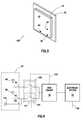
- FIG. 9illustrates a partial cut-away view of a patch antenna 900 in accordance with at least some embodiments.
- patch antenna 900comprises a radiative patch or antenna element 150 .
- the antenna element 150comprises a sheet of metallic material (e.g., copper) in the form of a square or rectangle that defines a perimeter.
- the patch antenna 900also comprises a ground plane or ground element 152 .
- the antenna element 150 and the ground element 152each define a plane, and those planes are substantially parallel in at least some embodiments.
- a dielectric materiale.g., printed circuit board material, silicon, plastic
- Radio frequency signalsare driven to the antenna element 150 by way of a feed point 154 , illustrated in FIG. 9 as an edge feed; however, in other embodiments multiple feed points along the edge or within the perimeter defined by the antenna element 150 may be used.
- FIG. 9also illustrates a plurality of ground posts 156 and 158 extending between and electrically coupling the ground element 152 to the antenna element 150 at the ground points 160 and 162 respectively. Although only two ground points 160 , 162 and two ground posts 156 , 158 are shown, any number of ground points may be equivalently used.
- polarization of the patch antenna 900is controlled, at least in part, by the number, placement and selective use of ground points. Thus, the polarization may be controlled not only by varying the feed points used, but also by varying quantity and/or location of ground points on the antenna element 150 .
- FIG. 10shows an electrical block diagram that illustrates coupling of the RFID reader 12 to the antenna element 150 in accordance with at least some embodiments.
- antenna element 150comprises an illustrative two ground points 160 and 162 , along with illustrative edge feed point 154 , as discussed with respect to FIG. 9 .
- Each ground point 160 , 162selectively couples to ground through a switch assembly 164 , which is illustrated as individual single-pole single-throw switches 166 and 168 .
- the switch assembly 164could be a single-pole double-throw switch.
- the switch assembly 164 and/or the individual switches 166 , 168physically reside between the antenna element 150 and the ground element 154 ( FIG. 9 ) to shorten the lead lengths between the ground points and the ground connection, but the switch assembly and/or switches may equivalently reside at any convenient location.
- the RFID reader 12 and/or electronic system 10are configured to transmit electromagnetic signals having an illustrative first polarization.
- switch 166is closed or made conducting, while switch 168 is opened or made non-conducting.
- the RFID reader 12generates an antenna feed signal, and the antenna feed signal is applied to the illustrative edge feed point 154 .
- the antenna element 150radiates an electromagnetic wave having the first polarization.
- switch 166is again closed or made conducting, while switch 168 is again opened or made non-conducting.
- the antenna element 150produces an electrical signal that moves between the illustrative edge feed point 154 and the RFID reader 12 , the electrical signal predominantly proportional to electromagnetic radiation incident upon the antenna element 150 having the first polarization.
- the RFID reader 12 and/or electronic system 10are configured to transmit electromagnetic signals having an illustrative second polarization, different than the first polarization.
- switch 168is closed or made conducting, while switch 166 is opened or made non-conducting.
- the RFID reader 12generates an antenna feed signal, and the antenna feed signal is applied to the illustrative edge feed point 154 .
- the antenna elementradiates an electromagnetic wave having the illustrative second polarization.
- the RFID reader 12 and/or electronic system 10are configured to receive electromagnetic signals with the second polarization.
- switch 168is again closed or made conducting, while switch 166 is again opened or made non-conducting.
- the antenna element 150produces an electrical signal that moves between the illustrative edge feed point 154 and the RFID reader 12 , the electrical signal predominantly proportional to the electromagnetic radiation incident upon the antenna element 120 having the second polarization.
- the switch assembly 164 used to selectively to ground the ground points 160 , 162may take many forms.
- one or more mechanical switchesare used, where the mechanic switches are closed (made conducting) or opened (made non-conducting) by physical manipulation of the switches (e.g. knife blade switches).
- the switch assembly 164is one ore more electrically controlled switches. Examples of electrically controlled switches that may be used are solenoid operated relays, or solid state switches (e.g. transistors, silicon controlled rectifier pairs).
- transistorse.g. transistors, silicon controlled rectifier pairs.
- MOSFETsmetal oxide semiconductor field effect transistors
- the device that controls the electrically controlled switches 166 and 168may vary as well.
- the RFID reader 12controls the switch positions of the illustrative switches, as shown by dashed line 170 in FIG. 10 .
- the electronic system 10controls the switch positions of the illustrative switches, as shown by dashed lines 172 in FIG. 10 .
- FIG. 11shows an RFID tag 16 in accordance with other embodiments.
- the RFID tag 16comprises antenna element 150 having at least two ground points 160 and 162 , each ground point associated with a different polarization antenna element 150 .
- the ground points 160 and 162couple to ground by way of a switch assembly 180 , which as illustrated is a single-pole double-throw switch, controlled by the RFID circuit 182 .
- the switch assembly 180may comprise individual switches (e.g. two single-pole single-throw switches).
- RFID tagsare, in most but not all cases, relatively small (e.g. credit card sized) objects, and thus while mechanical switches and solenoid controlled relays may be used as the switch assembly 180 , for size considerations the switch assembly 180 in most situations is solid state.
- the RFID circuit 182may be configured in many ways. In some embodiments the RFID circuit 182 controls the switch assembly 180 and transmits electromagnetic signals with particular polarization responsive to specific commands from an RFID reader. In other embodiments, the RFID circuit is pre-programmed to transmit electromagnetic signals of varying polarization, such as in a progression after each interrogation, or alternating polarizations based on successive interrogations.
Landscapes
- Waveguide Aerials (AREA)
- Variable-Direction Aerials And Aerial Arrays (AREA)
Abstract
Description
Claims (21)
Priority Applications (2)
| Application Number | Priority Date | Filing Date | Title |
|---|---|---|---|
| US11/740,393US7825867B2 (en) | 2007-04-26 | 2007-04-26 | Methods and systems of changing antenna polarization |
| US12/906,516US7932867B2 (en) | 2007-04-26 | 2010-10-18 | Methods and systems of changing antenna polarization |
Applications Claiming Priority (1)
| Application Number | Priority Date | Filing Date | Title |
|---|---|---|---|
| US11/740,393US7825867B2 (en) | 2007-04-26 | 2007-04-26 | Methods and systems of changing antenna polarization |
Related Child Applications (1)
| Application Number | Title | Priority Date | Filing Date |
|---|---|---|---|
| US12/906,516ContinuationUS7932867B2 (en) | 2007-04-26 | 2010-10-18 | Methods and systems of changing antenna polarization |
Publications (2)
| Publication Number | Publication Date |
|---|---|
| US20080266192A1 US20080266192A1 (en) | 2008-10-30 |
| US7825867B2true US7825867B2 (en) | 2010-11-02 |
Family
ID=39886327
Family Applications (2)
| Application Number | Title | Priority Date | Filing Date |
|---|---|---|---|
| US11/740,393Expired - Fee RelatedUS7825867B2 (en) | 2007-04-26 | 2007-04-26 | Methods and systems of changing antenna polarization |
| US12/906,516Expired - Fee RelatedUS7932867B2 (en) | 2007-04-26 | 2010-10-18 | Methods and systems of changing antenna polarization |
Family Applications After (1)
| Application Number | Title | Priority Date | Filing Date |
|---|---|---|---|
| US12/906,516Expired - Fee RelatedUS7932867B2 (en) | 2007-04-26 | 2010-10-18 | Methods and systems of changing antenna polarization |
Country Status (1)
| Country | Link |
|---|---|
| US (2) | US7825867B2 (en) |
Cited By (151)
| Publication number | Priority date | Publication date | Assignee | Title |
|---|---|---|---|---|
| US20090295545A1 (en)* | 2008-06-03 | 2009-12-03 | O'haire Michael | Method and System for Variable Operation of RFID-Based Readers Utilizing a Trigger Setting |
| US20100001921A1 (en)* | 2008-07-07 | 2010-01-07 | Sensormatic Electronics Corporation | Switchable patch antenna for rfid shelf reader system |
| US20100253583A1 (en)* | 2008-01-07 | 2010-10-07 | Fujitsu Limited | Electronic device, antenna and article |
| US20120313819A1 (en)* | 2011-06-13 | 2012-12-13 | Chia-Tien Li | Active Antenna and Electronic Device |
| US8405509B2 (en) | 2008-06-03 | 2013-03-26 | Micron Technology, Inc. | Systems and methods to selectively connect antennas to receive and backscatter radio frequency signals |
| US9608740B2 (en) | 2015-07-15 | 2017-03-28 | At&T Intellectual Property I, L.P. | Method and apparatus for launching a wave mode that mitigates interference |
| US9615269B2 (en) | 2014-10-02 | 2017-04-04 | At&T Intellectual Property I, L.P. | Method and apparatus that provides fault tolerance in a communication network |
| US9628116B2 (en) | 2015-07-14 | 2017-04-18 | At&T Intellectual Property I, L.P. | Apparatus and methods for transmitting wireless signals |
| US9640850B2 (en) | 2015-06-25 | 2017-05-02 | At&T Intellectual Property I, L.P. | Methods and apparatus for inducing a non-fundamental wave mode on a transmission medium |
| US9667317B2 (en) | 2015-06-15 | 2017-05-30 | At&T Intellectual Property I, L.P. | Method and apparatus for providing security using network traffic adjustments |
| US9674711B2 (en) | 2013-11-06 | 2017-06-06 | At&T Intellectual Property I, L.P. | Surface-wave communications and methods thereof |
| US9685992B2 (en) | 2014-10-03 | 2017-06-20 | At&T Intellectual Property I, L.P. | Circuit panel network and methods thereof |
| US9692101B2 (en) | 2014-08-26 | 2017-06-27 | At&T Intellectual Property I, L.P. | Guided wave couplers for coupling electromagnetic waves between a waveguide surface and a surface of a wire |
| US9699785B2 (en) | 2012-12-05 | 2017-07-04 | At&T Intellectual Property I, L.P. | Backhaul link for distributed antenna system |
| US9705561B2 (en) | 2015-04-24 | 2017-07-11 | At&T Intellectual Property I, L.P. | Directional coupling device and methods for use therewith |
| US9705610B2 (en) | 2014-10-21 | 2017-07-11 | At&T Intellectual Property I, L.P. | Transmission device with impairment compensation and methods for use therewith |
| US9722318B2 (en) | 2015-07-14 | 2017-08-01 | At&T Intellectual Property I, L.P. | Method and apparatus for coupling an antenna to a device |
| US9729197B2 (en) | 2015-10-01 | 2017-08-08 | At&T Intellectual Property I, L.P. | Method and apparatus for communicating network management traffic over a network |
| US9735833B2 (en) | 2015-07-31 | 2017-08-15 | At&T Intellectual Property I, L.P. | Method and apparatus for communications management in a neighborhood network |
| US9742521B2 (en) | 2014-11-20 | 2017-08-22 | At&T Intellectual Property I, L.P. | Transmission device with mode division multiplexing and methods for use therewith |
| US9742462B2 (en) | 2014-12-04 | 2017-08-22 | At&T Intellectual Property I, L.P. | Transmission medium and communication interfaces and methods for use therewith |
| US9748626B2 (en) | 2015-05-14 | 2017-08-29 | At&T Intellectual Property I, L.P. | Plurality of cables having different cross-sectional shapes which are bundled together to form a transmission medium |
| US9749013B2 (en) | 2015-03-17 | 2017-08-29 | At&T Intellectual Property I, L.P. | Method and apparatus for reducing attenuation of electromagnetic waves guided by a transmission medium |
| US9749053B2 (en) | 2015-07-23 | 2017-08-29 | At&T Intellectual Property I, L.P. | Node device, repeater and methods for use therewith |
| US9762289B2 (en) | 2014-10-14 | 2017-09-12 | At&T Intellectual Property I, L.P. | Method and apparatus for transmitting or receiving signals in a transportation system |
| US9768833B2 (en) | 2014-09-15 | 2017-09-19 | At&T Intellectual Property I, L.P. | Method and apparatus for sensing a condition in a transmission medium of electromagnetic waves |
| US9769020B2 (en) | 2014-10-21 | 2017-09-19 | At&T Intellectual Property I, L.P. | Method and apparatus for responding to events affecting communications in a communication network |
| US9769128B2 (en) | 2015-09-28 | 2017-09-19 | At&T Intellectual Property I, L.P. | Method and apparatus for encryption of communications over a network |
| US9780834B2 (en) | 2014-10-21 | 2017-10-03 | At&T Intellectual Property I, L.P. | Method and apparatus for transmitting electromagnetic waves |
| US9787412B2 (en) | 2015-06-25 | 2017-10-10 | At&T Intellectual Property I, L.P. | Methods and apparatus for inducing a fundamental wave mode on a transmission medium |
| US9793954B2 (en) | 2015-04-28 | 2017-10-17 | At&T Intellectual Property I, L.P. | Magnetic coupling device and methods for use therewith |
| US9793955B2 (en) | 2015-04-24 | 2017-10-17 | At&T Intellectual Property I, Lp | Passive electrical coupling device and methods for use therewith |
| US9793951B2 (en) | 2015-07-15 | 2017-10-17 | At&T Intellectual Property I, L.P. | Method and apparatus for launching a wave mode that mitigates interference |
| US9800327B2 (en) | 2014-11-20 | 2017-10-24 | At&T Intellectual Property I, L.P. | Apparatus for controlling operations of a communication device and methods thereof |
| US9820146B2 (en) | 2015-06-12 | 2017-11-14 | At&T Intellectual Property I, L.P. | Method and apparatus for authentication and identity management of communicating devices |
| US9838078B2 (en) | 2015-07-31 | 2017-12-05 | At&T Intellectual Property I, L.P. | Method and apparatus for exchanging communication signals |
| US9838896B1 (en) | 2016-12-09 | 2017-12-05 | At&T Intellectual Property I, L.P. | Method and apparatus for assessing network coverage |
| US9847850B2 (en) | 2014-10-14 | 2017-12-19 | At&T Intellectual Property I, L.P. | Method and apparatus for adjusting a mode of communication in a communication network |
| US9847566B2 (en) | 2015-07-14 | 2017-12-19 | At&T Intellectual Property I, L.P. | Method and apparatus for adjusting a field of a signal to mitigate interference |
| US9853342B2 (en) | 2015-07-14 | 2017-12-26 | At&T Intellectual Property I, L.P. | Dielectric transmission medium connector and methods for use therewith |
| US9860075B1 (en) | 2016-08-26 | 2018-01-02 | At&T Intellectual Property I, L.P. | Method and communication node for broadband distribution |
| US9866276B2 (en) | 2014-10-10 | 2018-01-09 | At&T Intellectual Property I, L.P. | Method and apparatus for arranging communication sessions in a communication system |
| US9865911B2 (en) | 2015-06-25 | 2018-01-09 | At&T Intellectual Property I, L.P. | Waveguide system for slot radiating first electromagnetic waves that are combined into a non-fundamental wave mode second electromagnetic wave on a transmission medium |
| US9866309B2 (en) | 2015-06-03 | 2018-01-09 | At&T Intellectual Property I, Lp | Host node device and methods for use therewith |
| US9871282B2 (en) | 2015-05-14 | 2018-01-16 | At&T Intellectual Property I, L.P. | At least one transmission medium having a dielectric surface that is covered at least in part by a second dielectric |
| US9871283B2 (en) | 2015-07-23 | 2018-01-16 | At&T Intellectual Property I, Lp | Transmission medium having a dielectric core comprised of plural members connected by a ball and socket configuration |
| US9871558B2 (en) | 2014-10-21 | 2018-01-16 | At&T Intellectual Property I, L.P. | Guided-wave transmission device and methods for use therewith |
| US9876571B2 (en) | 2015-02-20 | 2018-01-23 | At&T Intellectual Property I, Lp | Guided-wave transmission device with non-fundamental mode propagation and methods for use therewith |
| US9876264B2 (en) | 2015-10-02 | 2018-01-23 | At&T Intellectual Property I, Lp | Communication system, guided wave switch and methods for use therewith |
| US9876605B1 (en) | 2016-10-21 | 2018-01-23 | At&T Intellectual Property I, L.P. | Launcher and coupling system to support desired guided wave mode |
| US9882257B2 (en) | 2015-07-14 | 2018-01-30 | At&T Intellectual Property I, L.P. | Method and apparatus for launching a wave mode that mitigates interference |
| US9887447B2 (en) | 2015-05-14 | 2018-02-06 | At&T Intellectual Property I, L.P. | Transmission medium having multiple cores and methods for use therewith |
| US9893795B1 (en) | 2016-12-07 | 2018-02-13 | At&T Intellectual Property I, Lp | Method and repeater for broadband distribution |
| US9906269B2 (en) | 2014-09-17 | 2018-02-27 | At&T Intellectual Property I, L.P. | Monitoring and mitigating conditions in a communication network |
| US9904535B2 (en) | 2015-09-14 | 2018-02-27 | At&T Intellectual Property I, L.P. | Method and apparatus for distributing software |
| US9913139B2 (en) | 2015-06-09 | 2018-03-06 | At&T Intellectual Property I, L.P. | Signal fingerprinting for authentication of communicating devices |
| US9912419B1 (en) | 2016-08-24 | 2018-03-06 | At&T Intellectual Property I, L.P. | Method and apparatus for managing a fault in a distributed antenna system |
| US9911020B1 (en) | 2016-12-08 | 2018-03-06 | At&T Intellectual Property I, L.P. | Method and apparatus for tracking via a radio frequency identification device |
| US9912381B2 (en) | 2015-06-03 | 2018-03-06 | At&T Intellectual Property I, Lp | Network termination and methods for use therewith |
| US9912027B2 (en) | 2015-07-23 | 2018-03-06 | At&T Intellectual Property I, L.P. | Method and apparatus for exchanging communication signals |
| US9912033B2 (en) | 2014-10-21 | 2018-03-06 | At&T Intellectual Property I, Lp | Guided wave coupler, coupling module and methods for use therewith |
| US9917341B2 (en) | 2015-05-27 | 2018-03-13 | At&T Intellectual Property I, L.P. | Apparatus and method for launching electromagnetic waves and for modifying radial dimensions of the propagating electromagnetic waves |
| US9927517B1 (en) | 2016-12-06 | 2018-03-27 | At&T Intellectual Property I, L.P. | Apparatus and methods for sensing rainfall |
| US9930668B2 (en) | 2013-05-31 | 2018-03-27 | At&T Intellectual Property I, L.P. | Remote distributed antenna system |
| US9948354B2 (en) | 2015-04-28 | 2018-04-17 | At&T Intellectual Property I, L.P. | Magnetic coupling device with reflective plate and methods for use therewith |
| US9948355B2 (en) | 2014-10-21 | 2018-04-17 | At&T Intellectual Property I, L.P. | Apparatus for providing communication services and methods thereof |
| US9948333B2 (en) | 2015-07-23 | 2018-04-17 | At&T Intellectual Property I, L.P. | Method and apparatus for wireless communications to mitigate interference |
| US9954286B2 (en) | 2014-10-21 | 2018-04-24 | At&T Intellectual Property I, L.P. | Guided-wave transmission device with non-fundamental mode propagation and methods for use therewith |
| US9954287B2 (en) | 2014-11-20 | 2018-04-24 | At&T Intellectual Property I, L.P. | Apparatus for converting wireless signals and electromagnetic waves and methods thereof |
| US9967173B2 (en) | 2015-07-31 | 2018-05-08 | At&T Intellectual Property I, L.P. | Method and apparatus for authentication and identity management of communicating devices |
| US9973940B1 (en) | 2017-02-27 | 2018-05-15 | At&T Intellectual Property I, L.P. | Apparatus and methods for dynamic impedance matching of a guided wave launcher |
| US9991580B2 (en) | 2016-10-21 | 2018-06-05 | At&T Intellectual Property I, L.P. | Launcher and coupling system for guided wave mode cancellation |
| US9998870B1 (en) | 2016-12-08 | 2018-06-12 | At&T Intellectual Property I, L.P. | Method and apparatus for proximity sensing |
| US9999038B2 (en) | 2013-05-31 | 2018-06-12 | At&T Intellectual Property I, L.P. | Remote distributed antenna system |
| US9997819B2 (en) | 2015-06-09 | 2018-06-12 | At&T Intellectual Property I, L.P. | Transmission medium and method for facilitating propagation of electromagnetic waves via a core |
| US10009067B2 (en) | 2014-12-04 | 2018-06-26 | At&T Intellectual Property I, L.P. | Method and apparatus for configuring a communication interface |
| US10009065B2 (en) | 2012-12-05 | 2018-06-26 | At&T Intellectual Property I, L.P. | Backhaul link for distributed antenna system |
| US10009063B2 (en) | 2015-09-16 | 2018-06-26 | At&T Intellectual Property I, L.P. | Method and apparatus for use with a radio distributed antenna system having an out-of-band reference signal |
| US10020844B2 (en) | 2016-12-06 | 2018-07-10 | T&T Intellectual Property I, L.P. | Method and apparatus for broadcast communication via guided waves |
| US10027398B2 (en) | 2015-06-11 | 2018-07-17 | At&T Intellectual Property I, Lp | Repeater and methods for use therewith |
| US10027397B2 (en) | 2016-12-07 | 2018-07-17 | At&T Intellectual Property I, L.P. | Distributed antenna system and methods for use therewith |
| US10033108B2 (en) | 2015-07-14 | 2018-07-24 | At&T Intellectual Property I, L.P. | Apparatus and methods for generating an electromagnetic wave having a wave mode that mitigates interference |
| US10033107B2 (en) | 2015-07-14 | 2018-07-24 | At&T Intellectual Property I, L.P. | Method and apparatus for coupling an antenna to a device |
| US10044409B2 (en) | 2015-07-14 | 2018-08-07 | At&T Intellectual Property I, L.P. | Transmission medium and methods for use therewith |
| US10069535B2 (en) | 2016-12-08 | 2018-09-04 | At&T Intellectual Property I, L.P. | Apparatus and methods for launching electromagnetic waves having a certain electric field structure |
| US10079661B2 (en) | 2015-09-16 | 2018-09-18 | At&T Intellectual Property I, L.P. | Method and apparatus for use with a radio distributed antenna system having a clock reference |
| US10090606B2 (en) | 2015-07-15 | 2018-10-02 | At&T Intellectual Property I, L.P. | Antenna system with dielectric array and methods for use therewith |
| US10090594B2 (en) | 2016-11-23 | 2018-10-02 | At&T Intellectual Property I, L.P. | Antenna system having structural configurations for assembly |
| US10103801B2 (en) | 2015-06-03 | 2018-10-16 | At&T Intellectual Property I, L.P. | Host node device and methods for use therewith |
| US10103422B2 (en) | 2016-12-08 | 2018-10-16 | At&T Intellectual Property I, L.P. | Method and apparatus for mounting network devices |
| US10136434B2 (en) | 2015-09-16 | 2018-11-20 | At&T Intellectual Property I, L.P. | Method and apparatus for use with a radio distributed antenna system having an ultra-wideband control channel |
| US10135145B2 (en) | 2016-12-06 | 2018-11-20 | At&T Intellectual Property I, L.P. | Apparatus and methods for generating an electromagnetic wave along a transmission medium |
| US10135147B2 (en) | 2016-10-18 | 2018-11-20 | At&T Intellectual Property I, L.P. | Apparatus and methods for launching guided waves via an antenna |
| US10135146B2 (en) | 2016-10-18 | 2018-11-20 | At&T Intellectual Property I, L.P. | Apparatus and methods for launching guided waves via circuits |
| US10142086B2 (en) | 2015-06-11 | 2018-11-27 | At&T Intellectual Property I, L.P. | Repeater and methods for use therewith |
| US10139820B2 (en) | 2016-12-07 | 2018-11-27 | At&T Intellectual Property I, L.P. | Method and apparatus for deploying equipment of a communication system |
| US10144036B2 (en) | 2015-01-30 | 2018-12-04 | At&T Intellectual Property I, L.P. | Method and apparatus for mitigating interference affecting a propagation of electromagnetic waves guided by a transmission medium |
| US10148016B2 (en) | 2015-07-14 | 2018-12-04 | At&T Intellectual Property I, L.P. | Apparatus and methods for communicating utilizing an antenna array |
| US10170840B2 (en) | 2015-07-14 | 2019-01-01 | At&T Intellectual Property I, L.P. | Apparatus and methods for sending or receiving electromagnetic signals |
| US10168695B2 (en) | 2016-12-07 | 2019-01-01 | At&T Intellectual Property I, L.P. | Method and apparatus for controlling an unmanned aircraft |
| US10178445B2 (en) | 2016-11-23 | 2019-01-08 | At&T Intellectual Property I, L.P. | Methods, devices, and systems for load balancing between a plurality of waveguides |
| US10205655B2 (en) | 2015-07-14 | 2019-02-12 | At&T Intellectual Property I, L.P. | Apparatus and methods for communicating utilizing an antenna array and multiple communication paths |
| US10224634B2 (en) | 2016-11-03 | 2019-03-05 | At&T Intellectual Property I, L.P. | Methods and apparatus for adjusting an operational characteristic of an antenna |
| US10225025B2 (en) | 2016-11-03 | 2019-03-05 | At&T Intellectual Property I, L.P. | Method and apparatus for detecting a fault in a communication system |
| US10243270B2 (en) | 2016-12-07 | 2019-03-26 | At&T Intellectual Property I, L.P. | Beam adaptive multi-feed dielectric antenna system and methods for use therewith |
| US10243784B2 (en) | 2014-11-20 | 2019-03-26 | At&T Intellectual Property I, L.P. | System for generating topology information and methods thereof |
| US10264586B2 (en) | 2016-12-09 | 2019-04-16 | At&T Mobility Ii Llc | Cloud-based packet controller and methods for use therewith |
| US10291334B2 (en) | 2016-11-03 | 2019-05-14 | At&T Intellectual Property I, L.P. | System for detecting a fault in a communication system |
| US10291311B2 (en) | 2016-09-09 | 2019-05-14 | At&T Intellectual Property I, L.P. | Method and apparatus for mitigating a fault in a distributed antenna system |
| US10298293B2 (en) | 2017-03-13 | 2019-05-21 | At&T Intellectual Property I, L.P. | Apparatus of communication utilizing wireless network devices |
| US10305190B2 (en) | 2016-12-01 | 2019-05-28 | At&T Intellectual Property I, L.P. | Reflecting dielectric antenna system and methods for use therewith |
| US10312567B2 (en) | 2016-10-26 | 2019-06-04 | At&T Intellectual Property I, L.P. | Launcher with planar strip antenna and methods for use therewith |
| US10320586B2 (en) | 2015-07-14 | 2019-06-11 | At&T Intellectual Property I, L.P. | Apparatus and methods for generating non-interfering electromagnetic waves on an insulated transmission medium |
| US10326494B2 (en) | 2016-12-06 | 2019-06-18 | At&T Intellectual Property I, L.P. | Apparatus for measurement de-embedding and methods for use therewith |
| US10326689B2 (en) | 2016-12-08 | 2019-06-18 | At&T Intellectual Property I, L.P. | Method and system for providing alternative communication paths |
| US10340983B2 (en) | 2016-12-09 | 2019-07-02 | At&T Intellectual Property I, L.P. | Method and apparatus for surveying remote sites via guided wave communications |
| US10341142B2 (en) | 2015-07-14 | 2019-07-02 | At&T Intellectual Property I, L.P. | Apparatus and methods for generating non-interfering electromagnetic waves on an uninsulated conductor |
| US10340600B2 (en) | 2016-10-18 | 2019-07-02 | At&T Intellectual Property I, L.P. | Apparatus and methods for launching guided waves via plural waveguide systems |
| US10340573B2 (en) | 2016-10-26 | 2019-07-02 | At&T Intellectual Property I, L.P. | Launcher with cylindrical coupling device and methods for use therewith |
| US10340603B2 (en) | 2016-11-23 | 2019-07-02 | At&T Intellectual Property I, L.P. | Antenna system having shielded structural configurations for assembly |
| US10340601B2 (en) | 2016-11-23 | 2019-07-02 | At&T Intellectual Property I, L.P. | Multi-antenna system and methods for use therewith |
| US10355367B2 (en) | 2015-10-16 | 2019-07-16 | At&T Intellectual Property I, L.P. | Antenna structure for exchanging wireless signals |
| US10361489B2 (en) | 2016-12-01 | 2019-07-23 | At&T Intellectual Property I, L.P. | Dielectric dish antenna system and methods for use therewith |
| US10359749B2 (en) | 2016-12-07 | 2019-07-23 | At&T Intellectual Property I, L.P. | Method and apparatus for utilities management via guided wave communication |
| US10374316B2 (en) | 2016-10-21 | 2019-08-06 | At&T Intellectual Property I, L.P. | System and dielectric antenna with non-uniform dielectric |
| US10382976B2 (en) | 2016-12-06 | 2019-08-13 | At&T Intellectual Property I, L.P. | Method and apparatus for managing wireless communications based on communication paths and network device positions |
| US10389029B2 (en) | 2016-12-07 | 2019-08-20 | At&T Intellectual Property I, L.P. | Multi-feed dielectric antenna system with core selection and methods for use therewith |
| US10389037B2 (en) | 2016-12-08 | 2019-08-20 | At&T Intellectual Property I, L.P. | Apparatus and methods for selecting sections of an antenna array and use therewith |
| US10411356B2 (en) | 2016-12-08 | 2019-09-10 | At&T Intellectual Property I, L.P. | Apparatus and methods for selectively targeting communication devices with an antenna array |
| US10439675B2 (en) | 2016-12-06 | 2019-10-08 | At&T Intellectual Property I, L.P. | Method and apparatus for repeating guided wave communication signals |
| US10446936B2 (en) | 2016-12-07 | 2019-10-15 | At&T Intellectual Property I, L.P. | Multi-feed dielectric antenna system and methods for use therewith |
| US10498044B2 (en) | 2016-11-03 | 2019-12-03 | At&T Intellectual Property I, L.P. | Apparatus for configuring a surface of an antenna |
| US10530505B2 (en) | 2016-12-08 | 2020-01-07 | At&T Intellectual Property I, L.P. | Apparatus and methods for launching electromagnetic waves along a transmission medium |
| US10535928B2 (en) | 2016-11-23 | 2020-01-14 | At&T Intellectual Property I, L.P. | Antenna system and methods for use therewith |
| US10547348B2 (en) | 2016-12-07 | 2020-01-28 | At&T Intellectual Property I, L.P. | Method and apparatus for switching transmission mediums in a communication system |
| US10601494B2 (en) | 2016-12-08 | 2020-03-24 | At&T Intellectual Property I, L.P. | Dual-band communication device and method for use therewith |
| US10637149B2 (en) | 2016-12-06 | 2020-04-28 | At&T Intellectual Property I, L.P. | Injection molded dielectric antenna and methods for use therewith |
| US10650201B1 (en)* | 2011-08-02 | 2020-05-12 | Impinj, Inc. | RFID tags with port-dependent functionality |
| US10650940B2 (en) | 2015-05-15 | 2020-05-12 | At&T Intellectual Property I, L.P. | Transmission medium having a conductive material and methods for use therewith |
| US10665942B2 (en) | 2015-10-16 | 2020-05-26 | At&T Intellectual Property I, L.P. | Method and apparatus for adjusting wireless communications |
| US10694379B2 (en) | 2016-12-06 | 2020-06-23 | At&T Intellectual Property I, L.P. | Waveguide system with device-based authentication and methods for use therewith |
| US10727599B2 (en) | 2016-12-06 | 2020-07-28 | At&T Intellectual Property I, L.P. | Launcher with slot antenna and methods for use therewith |
| US10755542B2 (en) | 2016-12-06 | 2020-08-25 | At&T Intellectual Property I, L.P. | Method and apparatus for surveillance via guided wave communication |
| US10777873B2 (en) | 2016-12-08 | 2020-09-15 | At&T Intellectual Property I, L.P. | Method and apparatus for mounting network devices |
| US10797781B2 (en) | 2015-06-03 | 2020-10-06 | At&T Intellectual Property I, L.P. | Client node device and methods for use therewith |
| US10811767B2 (en) | 2016-10-21 | 2020-10-20 | At&T Intellectual Property I, L.P. | System and dielectric antenna with convex dielectric radome |
| US10819035B2 (en) | 2016-12-06 | 2020-10-27 | At&T Intellectual Property I, L.P. | Launcher with helical antenna and methods for use therewith |
| US10916969B2 (en) | 2016-12-08 | 2021-02-09 | At&T Intellectual Property I, L.P. | Method and apparatus for providing power using an inductive coupling |
| US10938108B2 (en) | 2016-12-08 | 2021-03-02 | At&T Intellectual Property I, L.P. | Frequency selective multi-feed dielectric antenna system and methods for use therewith |
| US11032819B2 (en) | 2016-09-15 | 2021-06-08 | At&T Intellectual Property I, L.P. | Method and apparatus for use with a radio distributed antenna system having a control channel reference signal |
| US20220059924A1 (en)* | 2019-10-24 | 2022-02-24 | Murata Manufacturing Co., Ltd. | Rfid reader/writer antenna device |
Families Citing this family (29)
| Publication number | Priority date | Publication date | Assignee | Title |
|---|---|---|---|---|
| US7936268B2 (en)* | 2007-08-31 | 2011-05-03 | Round Rock Research, Llc | Selectively coupling to feed points of an antenna system |
| CN101849320B (en)* | 2007-09-06 | 2015-12-16 | 德卡产品有限公司 | Rfid system and method |
| US20100016024A1 (en)* | 2008-07-21 | 2010-01-21 | Guangli Yang | Mobile Communications Device Diversity Antenna |
| US20100156607A1 (en)* | 2008-12-19 | 2010-06-24 | Thomas Lankes | Method for activating an RFID antenna and an associated RFID antenna system |
| TWI389415B (en)* | 2009-01-14 | 2013-03-11 | Mstar Semiconductor Inc | Radio frequency charging system and method |
| JP2010233077A (en)* | 2009-03-27 | 2010-10-14 | Brother Ind Ltd | Loop antenna unit |
| NL2007000C2 (en)* | 2011-06-27 | 2012-07-16 | Nedap Nv | RFID ANTENNA FOR TRANSMITTING AN ELECTROMAGNETIC INQUIRY FIELD AND RECEIVING REACTIONS FROM AN RFID LABEL SITUATED IN THE INQUIRY FIELD. |
| US11075662B2 (en)* | 2011-11-16 | 2021-07-27 | Duong Huy Ha | Radiation protector for mobile devices |
| US10608348B2 (en) | 2012-03-31 | 2020-03-31 | SeeScan, Inc. | Dual antenna systems with variable polarization |
| US9153867B2 (en)* | 2012-12-19 | 2015-10-06 | Futurewei Technologies, Inc. | Reconfigurable multiband antenna |
| TWI481205B (en)* | 2013-01-21 | 2015-04-11 | Wistron Neweb Corp | Microstrip antenna transceiver |
| CN103972655B (en)* | 2013-01-25 | 2016-09-28 | 启碁科技股份有限公司 | Microstrip Antenna Transceiver with Switchable Polarization |
| US10490908B2 (en) | 2013-03-15 | 2019-11-26 | SeeScan, Inc. | Dual antenna systems with variable polarization |
| TWI533513B (en) | 2014-03-04 | 2016-05-11 | 啟碁科技股份有限公司 | Planar dual polarization antenna |
| US9443121B2 (en)* | 2014-03-31 | 2016-09-13 | Symbol Technologies, Llc | Locally-powered, polarization-insensitive antenna for RFID reader, and RFID system for, and method of, scanning item tags with one or more such antennas |
| TWI547014B (en) | 2014-07-31 | 2016-08-21 | 啟碁科技股份有限公司 | Planar dual polarization antenna and complex antenna |
| TWI540791B (en) | 2014-11-05 | 2016-07-01 | 啟碁科技股份有限公司 | Planar dual polarization antenna and complex antenna |
| TWI563804B (en) | 2015-01-21 | 2016-12-21 | Wistron Neweb Corp | Microstrip antenna transceiver |
| CN108321543B (en)* | 2015-04-03 | 2021-04-16 | Oppo广东移动通信有限公司 | An antenna and electronic equipment |
| US10552651B1 (en)* | 2016-06-29 | 2020-02-04 | United States Of America As Represented By The Administrator Of The National Aeronautics And Space | Frequency multiplexed radio frequency identification |
| US9947993B2 (en)* | 2016-08-12 | 2018-04-17 | Microsoft Technology Licensing, Llc | Antenna stack |
| US10821350B1 (en)* | 2018-08-28 | 2020-11-03 | The Last Gameboard, INc. | Smart game board |
| US11942691B2 (en)* | 2018-11-02 | 2024-03-26 | Kyocera Corporation | Antenna, array antenna, wireless communication module, and wireless communication device |
| KR102551314B1 (en)* | 2018-12-18 | 2023-07-05 | 주식회사 아모텍 | Transmitter/receiver antenna system of repeater for lpwan and control method thereof |
| WO2020191610A1 (en) | 2019-03-26 | 2020-10-01 | 华为技术有限公司 | Smart antenna, antenna feeder system, antenna communication system and ap |
| US10651565B1 (en) | 2019-04-29 | 2020-05-12 | Microsoft Technology Licensing, Llc | Antenna polarization diversity |
| KR102375524B1 (en)* | 2019-12-10 | 2022-03-21 | 한국철도기술연구원 | Train Wireless Sensor Node Using RF Energy Harvesting |
| CN111146564B (en)* | 2019-12-27 | 2022-03-18 | 宇龙计算机通信科技(深圳)有限公司 | Radio frequency front-end circuit and terminal |
| EP4459789B1 (en) | 2023-05-03 | 2025-04-02 | Sick Ag | Antenna for rfid reader with polarization switching |
Citations (91)
| Publication number | Priority date | Publication date | Assignee | Title |
|---|---|---|---|---|
| US2256619A (en) | 1940-06-01 | 1941-09-23 | Rca Corp | Directional antenna |
| US3721990A (en) | 1971-12-27 | 1973-03-20 | Rca Corp | Physically small combined loop and dipole all channel television antenna system |
| US3727230A (en) | 1970-11-21 | 1973-04-10 | Sony Corp | Antenna having a combined dipole and loop portion |
| US3859652A (en) | 1972-06-26 | 1975-01-07 | North American Systems Corp | Method and apparatus for detecting the theft of articles |
| US3967202A (en) | 1974-07-25 | 1976-06-29 | Northern Illinois Gas Company | Data transmission system including an RF transponder for generating a broad spectrum of intelligence bearing sidebands |
| US4016553A (en) | 1975-06-27 | 1977-04-05 | Knogo Corporation | Article detection system with near field electromagnetic wave control |
| US4075632A (en) | 1974-08-27 | 1978-02-21 | The United States Of America As Represented By The United States Department Of Energy | Interrogation, and detection system |
| US4260983A (en) | 1978-01-11 | 1981-04-07 | Tag Radionics Limited | Presence sensing detector and system for detecting a receiver/transmitter device affixed to an article |
| US4274083A (en) | 1977-12-16 | 1981-06-16 | Eiichi Tomoeda | Apparatus for identifying moving objects |
| US4333072A (en) | 1979-08-06 | 1982-06-01 | International Identification Incorporated | Identification device |
| US4510495A (en) | 1982-08-09 | 1985-04-09 | Cornell Research Foundation, Inc. | Remote passive identification system |
| US4525713A (en) | 1983-03-01 | 1985-06-25 | Lockheed Electronics Co., Inc. | Electronic tag identification system |
| US4539660A (en) | 1980-12-26 | 1985-09-03 | Hitachi, Ltd. | Semiconductor integrated circuit |
| US4572976A (en) | 1982-12-10 | 1986-02-25 | N.V. Nederlandsche Apparatenfabriek Nedap | Transponder for electromagnetic detection system with non-linear circuit |
| US4596988A (en) | 1983-06-10 | 1986-06-24 | Wanka James T | Remote controlled tracking transmitter and tracking support system |
| US4630044A (en) | 1982-12-23 | 1986-12-16 | Ant Nachrichtentechnik Gmbh | Programmable inductively coupled transponder |
| US4641374A (en) | 1984-08-08 | 1987-02-03 | Kabushiki Kaisha Toshiba | Information medium |
| US4646090A (en) | 1983-08-12 | 1987-02-24 | Rca Corporation | Codeable identifying tag and method of identification thereof |
| US4651157A (en) | 1985-05-07 | 1987-03-17 | Mets, Inc. | Security monitoring and tracking system |
| US4654658A (en) | 1984-08-03 | 1987-03-31 | Walton Charles A | Identification system with vector phase angle detection |
| US4656472A (en) | 1985-01-23 | 1987-04-07 | Walton Charles A | Proximity identification system with power aided identifier |
| US4724427A (en) | 1986-07-18 | 1988-02-09 | B. I. Incorporated | Transponder device |
| US4730188A (en) | 1984-02-15 | 1988-03-08 | Identification Devices, Inc. | Identification system |
| US4740792A (en) | 1986-08-27 | 1988-04-26 | Hughes Aircraft Company | Vehicle location system |
| US4782342A (en) | 1986-08-04 | 1988-11-01 | Walton Charles A | Proximity identification system with lateral flux paths |
| USRE32856E (en) | 1984-04-10 | 1989-02-07 | Peter Miller | Alarm system |
| US4809009A (en) | 1988-01-25 | 1989-02-28 | Grimes Dale M | Resonant antenna |
| US4819053A (en) | 1986-05-09 | 1989-04-04 | Halavais Richard A | Single-point locating system |
| US4822990A (en) | 1985-11-29 | 1989-04-18 | Kabushiki Kaisha Toshiba | Admission control system having a transponder actuated by an inquiry signal |
| US4854328A (en) | 1987-03-23 | 1989-08-08 | Philip Pollack | Animal monitoring telltale and information system |
| US4857893A (en) | 1986-07-18 | 1989-08-15 | Bi Inc. | Single chip transponder device |
| US4862160A (en) | 1983-12-29 | 1989-08-29 | Revlon, Inc. | Item identification tag for rapid inventory data acquisition system |
| US4870419A (en) | 1980-02-13 | 1989-09-26 | Eid Electronic Identification Systems, Ltd. | Electronic identification system |
| US4888591A (en) | 1988-10-06 | 1989-12-19 | Amtech Technology Corporation | Signal discrimination system |
| US4890072A (en) | 1988-02-03 | 1989-12-26 | Motorola, Inc. | Phase locked loop having a fast lock current reduction and clamping circuit |
| US4890075A (en) | 1986-07-31 | 1989-12-26 | The United States Of America As Represented By The Secretary Of The Army | Optical radiation limiter |
| US4904983A (en) | 1986-06-05 | 1990-02-27 | Steven Mitchell | Alarm system |
| US4912471A (en) | 1983-11-03 | 1990-03-27 | Mitron Systems Corporation | Interrogator-responder communication system |
| US4918458A (en) | 1979-05-30 | 1990-04-17 | Anton Brunner | Secondary radar transponder |
| US4920450A (en) | 1989-06-23 | 1990-04-24 | Motorola, Inc. | Temperature dependent capacitor |
| US4926182A (en) | 1986-05-30 | 1990-05-15 | Sharp Kabushiki Kaisha | Microwave data transmission apparatus |
| US4937581A (en) | 1980-02-13 | 1990-06-26 | Eid Electronic Identification Systems Ltd. | Electronic identification system |
| US5046130A (en) | 1989-08-08 | 1991-09-03 | Motorola, Inc. | Multiple communication path compatible automatic vehicle location unit |
| US5051726A (en) | 1990-08-14 | 1991-09-24 | Sensormatic Electronics Corporation | Electronic article surveillance system with antenna array for enhanced field falloff |
| US5055851A (en) | 1988-05-16 | 1991-10-08 | Trackmobile, Inc. | Vehicle location system |
| US5084699A (en) | 1989-05-26 | 1992-01-28 | Trovan Limited | Impedance matching coil assembly for an inductively coupled transponder |
| US5086389A (en) | 1990-05-17 | 1992-02-04 | Hassett John J | Automatic toll processing apparatus |
| US5103235A (en) | 1988-12-30 | 1992-04-07 | Checkpoint Systems, Inc. | Antenna structure for an electronic article surveillance system |
| US5126749A (en) | 1989-08-25 | 1992-06-30 | Kaltner George W | Individually fed multiloop antennas for electronic security systems |
| US5134085A (en) | 1991-11-21 | 1992-07-28 | Micron Technology, Inc. | Reduced-mask, split-polysilicon CMOS process, incorporating stacked-capacitor cells, for fabricating multi-megabit dynamic random access memories |
| US5136719A (en) | 1988-12-05 | 1992-08-04 | Seiko Corp. | Automatic antenna tubing method and apparatus |
| US5142292A (en) | 1991-08-05 | 1992-08-25 | Checkpoint Systems, Inc. | Coplanar multiple loop antenna for electronic article surveillance systems |
| US5144314A (en) | 1987-10-23 | 1992-09-01 | Allen-Bradley Company, Inc. | Programmable object identification transponder system |
| US5164985A (en)* | 1987-10-27 | 1992-11-17 | Nysen Paul A | Passive universal communicator system |
| US5175774A (en) | 1990-10-16 | 1992-12-29 | Micron Technology, Inc. | Semiconductor wafer marking for identification during processing |
| US5198826A (en) | 1989-09-22 | 1993-03-30 | Nippon Sheet Glass Co., Ltd. | Wide-band loop antenna with outer and inner loop conductors |
| US5272367A (en) | 1988-05-02 | 1993-12-21 | Micron Technology, Inc. | Fabrication of complementary n-channel and p-channel circuits (ICs) useful in the manufacture of dynamic random access memories (drams) |
| US5287112A (en) | 1993-04-14 | 1994-02-15 | Texas Instruments Incorporated | High speed read/write AVI system |
| US5300875A (en) | 1992-06-08 | 1994-04-05 | Micron Technology, Inc. | Passive (non-contact) recharging of secondary battery cell(s) powering RFID transponder tags |
| US5323150A (en) | 1992-06-11 | 1994-06-21 | Micron Technology, Inc. | Method for reducing conductive and convective heat loss from the battery in an RFID tag or other battery-powered devices |
| US5334974A (en) | 1992-02-06 | 1994-08-02 | Simms James R | Personal security system |
| US5365551A (en) | 1992-12-15 | 1994-11-15 | Micron Technology, Inc. | Data communication transceiver using identification protocol |
| US5406263A (en) | 1992-07-27 | 1995-04-11 | Micron Communications, Inc. | Anti-theft method for detecting the unauthorized opening of containers and baggage |
| US5420757A (en) | 1993-02-11 | 1995-05-30 | Indala Corporation | Method of producing a radio frequency transponder with a molded environmentally sealed package |
| US5446447A (en) | 1994-02-16 | 1995-08-29 | Motorola, Inc. | RF tagging system including RF tags with variable frequency resonant circuits |
| US5448242A (en) | 1994-04-26 | 1995-09-05 | Texas Instruments Incorporated | Modulation field detection, method and structure |
| US5448110A (en) | 1992-06-17 | 1995-09-05 | Micron Communications, Inc. | Enclosed transceiver |
| US5461385A (en) | 1994-04-29 | 1995-10-24 | Hughes Identification Devices, Inc. | RF/ID transponder system employing multiple transponders and a sensor switch |
| US5471212A (en) | 1994-04-26 | 1995-11-28 | Texas Instruments Incorporated | Multi-stage transponder wake-up, method and structure |
| US5479172A (en) | 1994-02-10 | 1995-12-26 | Racom Systems, Inc. | Power supply and power enable circuit for an RF/ID transponder |
| US5479416A (en) | 1993-09-30 | 1995-12-26 | Micron Technology, Inc. | Apparatus and method for error detection and correction in radio frequency identification device |
| US5489546A (en) | 1995-05-24 | 1996-02-06 | Micron Technology, Inc. | Method of forming CMOS devices using independent thickness spacers in a split-polysilicon DRAM process |
| US5500650A (en) | 1992-12-15 | 1996-03-19 | Micron Technology, Inc. | Data communication method using identification protocol |
| US5519621A (en) | 1991-01-17 | 1996-05-21 | Highwaymaster Communications, Inc. | Vehicle locating and communicating method and apparatus |
| US5521600A (en) | 1994-09-06 | 1996-05-28 | The Regents Of The University Of California | Range-gated field disturbance sensor with range-sensitivity compensation |
| US5525993A (en) | 1995-05-12 | 1996-06-11 | The Regents Of The University Of California | Microwave noncontact identification transponder using subharmonic interrogation and method of using the same |
| US5572226A (en) | 1992-05-15 | 1996-11-05 | Micron Technology, Inc. | Spherical antenna pattern(s) from antenna(s) arranged in a two-dimensional plane for use in RFID tags and labels |
| US5649296A (en) | 1995-06-19 | 1997-07-15 | Lucent Technologies Inc. | Full duplex modulated backscatter system |
| US5656978A (en) | 1995-12-11 | 1997-08-12 | Harmonic Lightwaves | Control circuit and method for direct current controlled attenuator |
| US5668560A (en) | 1995-01-30 | 1997-09-16 | Ncr Corporation | Wireless electronic module |
| US5894266A (en) | 1996-05-30 | 1999-04-13 | Micron Technology, Inc. | Method and apparatus for remote monitoring |
| US5970398A (en) | 1996-07-30 | 1999-10-19 | Micron Communications, Inc. | Radio frequency antenna with current controlled sensitivity |
| US6243013B1 (en) | 1999-01-08 | 2001-06-05 | Intermec Ip Corp. | Cascaded DC voltages of multiple antenna RF tag front-end circuits |
| US6434368B1 (en) | 1998-10-27 | 2002-08-13 | Telefonaktiebolaget Lm Ericsson (Publ) | Diode-based switch for a radio transceiver |
| US6466131B1 (en) | 1996-07-30 | 2002-10-15 | Micron Technology, Inc. | Radio frequency data communications device with adjustable receiver sensitivity and method |
| US6466634B1 (en) | 1996-05-13 | 2002-10-15 | Micron Technology, Inc. | Radio frequency data communications device |
| US20030174099A1 (en)* | 2002-01-09 | 2003-09-18 | Westvaco Corporation | Intelligent station using multiple RF antennae and inventory control system and method incorporating same |
| US20050083179A1 (en) | 2000-06-06 | 2005-04-21 | Battelle Memorial Institute | Phase modulation in RF tag |
| US20060007044A1 (en) | 2004-07-01 | 2006-01-12 | Crouch David D | Multiple-port patch antenna |
| US20070152831A1 (en)* | 2006-01-05 | 2007-07-05 | Sean Eisele | 3-axis RFID tag antenna |
| US20090058649A1 (en) | 2007-08-31 | 2009-03-05 | Micron Technology, Inc. | Selectively coupling to feed points of an antenna system |
Family Cites Families (5)
| Publication number | Priority date | Publication date | Assignee | Title |
|---|---|---|---|---|
| US5400203A (en)* | 1992-07-29 | 1995-03-21 | Pittway Corporation, A Delaware Corporation | Short circuit detector and isolator |
| US6292153B1 (en)* | 1999-08-27 | 2001-09-18 | Fantasma Network, Inc. | Antenna comprising two wideband notch regions on one coplanar substrate |
| US7450076B1 (en)* | 2007-06-28 | 2008-11-11 | Cheng Uei Precision Industry Co., Ltd. | Integrated multi-band antenna |
| DE102007061305B4 (en)* | 2007-12-19 | 2012-04-26 | Continental Automotive Gmbh | Multipart antenna with circular polarization and radio station |
| US20100123629A1 (en)* | 2008-11-14 | 2010-05-20 | Cheng Uei Precision Industry Co., Ltd. | Dual-Polarized Antenna |
- 2007
- 2007-04-26USUS11/740,393patent/US7825867B2/ennot_activeExpired - Fee Related
- 2010
- 2010-10-18USUS12/906,516patent/US7932867B2/ennot_activeExpired - Fee Related
Patent Citations (96)
| Publication number | Priority date | Publication date | Assignee | Title |
|---|---|---|---|---|
| US2256619A (en) | 1940-06-01 | 1941-09-23 | Rca Corp | Directional antenna |
| US3727230A (en) | 1970-11-21 | 1973-04-10 | Sony Corp | Antenna having a combined dipole and loop portion |
| US3721990A (en) | 1971-12-27 | 1973-03-20 | Rca Corp | Physically small combined loop and dipole all channel television antenna system |
| US3859652A (en) | 1972-06-26 | 1975-01-07 | North American Systems Corp | Method and apparatus for detecting the theft of articles |
| US3967202A (en) | 1974-07-25 | 1976-06-29 | Northern Illinois Gas Company | Data transmission system including an RF transponder for generating a broad spectrum of intelligence bearing sidebands |
| US4075632A (en) | 1974-08-27 | 1978-02-21 | The United States Of America As Represented By The United States Department Of Energy | Interrogation, and detection system |
| US4016553A (en) | 1975-06-27 | 1977-04-05 | Knogo Corporation | Article detection system with near field electromagnetic wave control |
| US4274083A (en) | 1977-12-16 | 1981-06-16 | Eiichi Tomoeda | Apparatus for identifying moving objects |
| US4260983A (en) | 1978-01-11 | 1981-04-07 | Tag Radionics Limited | Presence sensing detector and system for detecting a receiver/transmitter device affixed to an article |
| US4918458A (en) | 1979-05-30 | 1990-04-17 | Anton Brunner | Secondary radar transponder |
| US4333072A (en) | 1979-08-06 | 1982-06-01 | International Identification Incorporated | Identification device |
| US4870419A (en) | 1980-02-13 | 1989-09-26 | Eid Electronic Identification Systems, Ltd. | Electronic identification system |
| US4937581A (en) | 1980-02-13 | 1990-06-26 | Eid Electronic Identification Systems Ltd. | Electronic identification system |
| US4539660A (en) | 1980-12-26 | 1985-09-03 | Hitachi, Ltd. | Semiconductor integrated circuit |
| US4510495A (en) | 1982-08-09 | 1985-04-09 | Cornell Research Foundation, Inc. | Remote passive identification system |
| US4572976A (en) | 1982-12-10 | 1986-02-25 | N.V. Nederlandsche Apparatenfabriek Nedap | Transponder for electromagnetic detection system with non-linear circuit |
| US4630044A (en) | 1982-12-23 | 1986-12-16 | Ant Nachrichtentechnik Gmbh | Programmable inductively coupled transponder |
| US4525713A (en) | 1983-03-01 | 1985-06-25 | Lockheed Electronics Co., Inc. | Electronic tag identification system |
| US4596988A (en) | 1983-06-10 | 1986-06-24 | Wanka James T | Remote controlled tracking transmitter and tracking support system |
| US4646090A (en) | 1983-08-12 | 1987-02-24 | Rca Corporation | Codeable identifying tag and method of identification thereof |
| US4912471A (en) | 1983-11-03 | 1990-03-27 | Mitron Systems Corporation | Interrogator-responder communication system |
| US4862160A (en) | 1983-12-29 | 1989-08-29 | Revlon, Inc. | Item identification tag for rapid inventory data acquisition system |
| US4730188A (en) | 1984-02-15 | 1988-03-08 | Identification Devices, Inc. | Identification system |
| USRE32856E (en) | 1984-04-10 | 1989-02-07 | Peter Miller | Alarm system |
| US4654658A (en) | 1984-08-03 | 1987-03-31 | Walton Charles A | Identification system with vector phase angle detection |
| US4641374A (en) | 1984-08-08 | 1987-02-03 | Kabushiki Kaisha Toshiba | Information medium |
| US4656472A (en) | 1985-01-23 | 1987-04-07 | Walton Charles A | Proximity identification system with power aided identifier |
| US4651157A (en) | 1985-05-07 | 1987-03-17 | Mets, Inc. | Security monitoring and tracking system |
| US4822990A (en) | 1985-11-29 | 1989-04-18 | Kabushiki Kaisha Toshiba | Admission control system having a transponder actuated by an inquiry signal |
| US4819053A (en) | 1986-05-09 | 1989-04-04 | Halavais Richard A | Single-point locating system |
| US4926182A (en) | 1986-05-30 | 1990-05-15 | Sharp Kabushiki Kaisha | Microwave data transmission apparatus |
| US4904983A (en) | 1986-06-05 | 1990-02-27 | Steven Mitchell | Alarm system |
| US4724427A (en) | 1986-07-18 | 1988-02-09 | B. I. Incorporated | Transponder device |
| US4857893A (en) | 1986-07-18 | 1989-08-15 | Bi Inc. | Single chip transponder device |
| US4890075A (en) | 1986-07-31 | 1989-12-26 | The United States Of America As Represented By The Secretary Of The Army | Optical radiation limiter |
| US4782342A (en) | 1986-08-04 | 1988-11-01 | Walton Charles A | Proximity identification system with lateral flux paths |
| US4740792A (en) | 1986-08-27 | 1988-04-26 | Hughes Aircraft Company | Vehicle location system |
| US4854328A (en) | 1987-03-23 | 1989-08-08 | Philip Pollack | Animal monitoring telltale and information system |
| US5144314A (en) | 1987-10-23 | 1992-09-01 | Allen-Bradley Company, Inc. | Programmable object identification transponder system |
| US5164985A (en)* | 1987-10-27 | 1992-11-17 | Nysen Paul A | Passive universal communicator system |
| US4809009A (en) | 1988-01-25 | 1989-02-28 | Grimes Dale M | Resonant antenna |
| US4890072A (en) | 1988-02-03 | 1989-12-26 | Motorola, Inc. | Phase locked loop having a fast lock current reduction and clamping circuit |
| US5272367A (en) | 1988-05-02 | 1993-12-21 | Micron Technology, Inc. | Fabrication of complementary n-channel and p-channel circuits (ICs) useful in the manufacture of dynamic random access memories (drams) |
| US5055851A (en) | 1988-05-16 | 1991-10-08 | Trackmobile, Inc. | Vehicle location system |
| US4888591A (en) | 1988-10-06 | 1989-12-19 | Amtech Technology Corporation | Signal discrimination system |
| US5136719A (en) | 1988-12-05 | 1992-08-04 | Seiko Corp. | Automatic antenna tubing method and apparatus |
| US5103235A (en) | 1988-12-30 | 1992-04-07 | Checkpoint Systems, Inc. | Antenna structure for an electronic article surveillance system |
| US5084699A (en) | 1989-05-26 | 1992-01-28 | Trovan Limited | Impedance matching coil assembly for an inductively coupled transponder |
| US4920450A (en) | 1989-06-23 | 1990-04-24 | Motorola, Inc. | Temperature dependent capacitor |
| US5046130A (en) | 1989-08-08 | 1991-09-03 | Motorola, Inc. | Multiple communication path compatible automatic vehicle location unit |
| US5126749A (en) | 1989-08-25 | 1992-06-30 | Kaltner George W | Individually fed multiloop antennas for electronic security systems |
| US5198826A (en) | 1989-09-22 | 1993-03-30 | Nippon Sheet Glass Co., Ltd. | Wide-band loop antenna with outer and inner loop conductors |
| US5086389A (en) | 1990-05-17 | 1992-02-04 | Hassett John J | Automatic toll processing apparatus |
| US5051726A (en) | 1990-08-14 | 1991-09-24 | Sensormatic Electronics Corporation | Electronic article surveillance system with antenna array for enhanced field falloff |
| US5175774A (en) | 1990-10-16 | 1992-12-29 | Micron Technology, Inc. | Semiconductor wafer marking for identification during processing |
| US5519621A (en) | 1991-01-17 | 1996-05-21 | Highwaymaster Communications, Inc. | Vehicle locating and communicating method and apparatus |
| US5142292A (en) | 1991-08-05 | 1992-08-25 | Checkpoint Systems, Inc. | Coplanar multiple loop antenna for electronic article surveillance systems |
| US5134085A (en) | 1991-11-21 | 1992-07-28 | Micron Technology, Inc. | Reduced-mask, split-polysilicon CMOS process, incorporating stacked-capacitor cells, for fabricating multi-megabit dynamic random access memories |
| US5334974A (en) | 1992-02-06 | 1994-08-02 | Simms James R | Personal security system |
| US5719586A (en) | 1992-05-15 | 1998-02-17 | Micron Communications, Inc. | Spherical antenna pattern(s) from antenna(s) arranged in a two-dimensional plane for use in RFID tags and labels |
| US5572226A (en) | 1992-05-15 | 1996-11-05 | Micron Technology, Inc. | Spherical antenna pattern(s) from antenna(s) arranged in a two-dimensional plane for use in RFID tags and labels |
| US5300875A (en) | 1992-06-08 | 1994-04-05 | Micron Technology, Inc. | Passive (non-contact) recharging of secondary battery cell(s) powering RFID transponder tags |
| US5323150A (en) | 1992-06-11 | 1994-06-21 | Micron Technology, Inc. | Method for reducing conductive and convective heat loss from the battery in an RFID tag or other battery-powered devices |
| US5448110A (en) | 1992-06-17 | 1995-09-05 | Micron Communications, Inc. | Enclosed transceiver |
| US5406263A (en) | 1992-07-27 | 1995-04-11 | Micron Communications, Inc. | Anti-theft method for detecting the unauthorized opening of containers and baggage |
| US5365551A (en) | 1992-12-15 | 1994-11-15 | Micron Technology, Inc. | Data communication transceiver using identification protocol |
| US5500650A (en) | 1992-12-15 | 1996-03-19 | Micron Technology, Inc. | Data communication method using identification protocol |
| US5420757A (en) | 1993-02-11 | 1995-05-30 | Indala Corporation | Method of producing a radio frequency transponder with a molded environmentally sealed package |
| US5374930A (en) | 1993-04-14 | 1994-12-20 | Texas Instruments Deutschland Gmbh | High speed read/write AVI system |
| US5287112A (en) | 1993-04-14 | 1994-02-15 | Texas Instruments Incorporated | High speed read/write AVI system |
| US5479416A (en) | 1993-09-30 | 1995-12-26 | Micron Technology, Inc. | Apparatus and method for error detection and correction in radio frequency identification device |
| US5479172A (en) | 1994-02-10 | 1995-12-26 | Racom Systems, Inc. | Power supply and power enable circuit for an RF/ID transponder |
| US5446447A (en) | 1994-02-16 | 1995-08-29 | Motorola, Inc. | RF tagging system including RF tags with variable frequency resonant circuits |
| US5621412A (en) | 1994-04-26 | 1997-04-15 | Texas Instruments Incorporated | Multi-stage transponder wake-up, method and structure |
| US5448242A (en) | 1994-04-26 | 1995-09-05 | Texas Instruments Incorporated | Modulation field detection, method and structure |
| US5471212A (en) | 1994-04-26 | 1995-11-28 | Texas Instruments Incorporated | Multi-stage transponder wake-up, method and structure |
| US5461385A (en) | 1994-04-29 | 1995-10-24 | Hughes Identification Devices, Inc. | RF/ID transponder system employing multiple transponders and a sensor switch |
| US5521600A (en) | 1994-09-06 | 1996-05-28 | The Regents Of The University Of California | Range-gated field disturbance sensor with range-sensitivity compensation |
| US5668560A (en) | 1995-01-30 | 1997-09-16 | Ncr Corporation | Wireless electronic module |
| US5525993A (en) | 1995-05-12 | 1996-06-11 | The Regents Of The University Of California | Microwave noncontact identification transponder using subharmonic interrogation and method of using the same |
| US5489546A (en) | 1995-05-24 | 1996-02-06 | Micron Technology, Inc. | Method of forming CMOS devices using independent thickness spacers in a split-polysilicon DRAM process |
| US5649296A (en) | 1995-06-19 | 1997-07-15 | Lucent Technologies Inc. | Full duplex modulated backscatter system |
| US5656978A (en) | 1995-12-11 | 1997-08-12 | Harmonic Lightwaves | Control circuit and method for direct current controlled attenuator |
| US6466634B1 (en) | 1996-05-13 | 2002-10-15 | Micron Technology, Inc. | Radio frequency data communications device |
| US5894266A (en) | 1996-05-30 | 1999-04-13 | Micron Technology, Inc. | Method and apparatus for remote monitoring |
| US5970398A (en) | 1996-07-30 | 1999-10-19 | Micron Communications, Inc. | Radio frequency antenna with current controlled sensitivity |
| US6122494A (en) | 1996-07-30 | 2000-09-19 | Micron Technology, Inc. | Radio frequency antenna with current controlled sensitivity |
| US6574454B1 (en) | 1996-07-30 | 2003-06-03 | Micron Technology, Inc. | Radio frequency antenna with current controlled sensitivity |
| US6466131B1 (en) | 1996-07-30 | 2002-10-15 | Micron Technology, Inc. | Radio frequency data communications device with adjustable receiver sensitivity and method |
| US6434368B1 (en) | 1998-10-27 | 2002-08-13 | Telefonaktiebolaget Lm Ericsson (Publ) | Diode-based switch for a radio transceiver |
| US6243013B1 (en) | 1999-01-08 | 2001-06-05 | Intermec Ip Corp. | Cascaded DC voltages of multiple antenna RF tag front-end circuits |
| US20050083179A1 (en) | 2000-06-06 | 2005-04-21 | Battelle Memorial Institute | Phase modulation in RF tag |
| US20030174099A1 (en)* | 2002-01-09 | 2003-09-18 | Westvaco Corporation | Intelligent station using multiple RF antennae and inventory control system and method incorporating same |
| US20060007044A1 (en) | 2004-07-01 | 2006-01-12 | Crouch David D | Multiple-port patch antenna |
| US20070152831A1 (en)* | 2006-01-05 | 2007-07-05 | Sean Eisele | 3-axis RFID tag antenna |
| US20090058649A1 (en) | 2007-08-31 | 2009-03-05 | Micron Technology, Inc. | Selectively coupling to feed points of an antenna system |
Non-Patent Citations (24)
| Title |
|---|
| Beebe, Paul, "High-Tech Rules Ada," The Idaho Statesman, Jul. 11, 1993, reprinted in "Micron Morning Report," Jul. 16, 1993. |
| Eric Krantz and Dr. Stuart Riley, "GPS Antenna Design and Performance Advancements: The Trimble Sephyr," Trimble GPS Engineering and Construction Group, Sunnyvale, California, Pete Large, Trimble Integrated Surveying Group, Westminster, Colorado. |
| J.T. Bernhard, et al., A Commemoration of Deschamps' and Sichak's "Microstrip Microwave Antennas": 50 Years of Development, Divergence, and New Directions; Electromagnetics Laboratory, ECE Department, University of Illinois at Urbana-Campaign, Urbana, IL 61801 Antenna Laboratory, ECE Department, University of Massachusetts, Amherst, MA 01003; Air Force Research Laboratory, Sensors Directorate 80 Scott Drive, Hanscom AFB, MA 01731. |
| Johnson, Cameron et al., "Data Transmission via Polarization Modulation of a 2.4 Ghz Circulary Polarized Radio Wave", Students of Advanced Laboratory, Department of Physics, UMR. |
| Mitsubishi Motors Corporation, "Eclipse: Safety and Security," located at http://www.mitsubishi-motors.co.jp.r/products/Eclipse/eclipse-04.html, 1995. |
| O'Toole, James E., U.S. Appl. No. 60/017,900, filed May 13, 1996. |
| Transaction History of related U.S. Appl. No. 08/422,007, filed Apr. 11, 1995, entitled "Spherical Antenna Pattern(s) From Antenna(s) Arranged in a Two-Dimensional Plane for Use in RFID Tags and Labels," now U. S. Patent No. 5,572,226. |
| Transaction History of related U.S. Appl. No. 08/584,788, filed Jan. 1, 1996, entitled "Spherical Antenna Pattern(s) From Antenna(s) Arranged in a Two-Dimensional Plane for Use in RFID Tags and Labels," now U. S. Patent No. 5,719,586. |
| Transaction History of related U.S. Appl. No. 08/656,530, filed May 30, 1996, entitled "Method and Apparatus for Remote Monitoring," now U.S. Patent No. 5,894,266. |
| Transaction History of related U.S. Appl. No. 08/704,965, filed Aug. 29, 1996, entitled "Radio Frequency Antenna with Current Controlled Sensitivity," now U.S. Patent No. 5,970,398. |
| Transaction History of related U.S. Appl. No. 09/172,714, filed Oct. 13, 1998, entitled "Radio Frequency Antenna with Current Controlled Sensitivity," now U.S. Patent No. 6,122,494. |
| Transaction History of related U.S. Appl. No. 09/542,800, filed Apr. 4, 2000, entitled "Radio Frequency Antenna with Current Controlled Sensitivity," now U.S. Patent No. 6,574,454. |
| Transaction History of related U.S. Appl. No. 11/848,295, filed Aug. 31, 2007, entitled "Selectively Coupling to Feed Points of an Antenna System." |
| Transaction History of related U.S. Appl. No. 12/132,594, filed Jun. 3, 2008, entitled "Systems and Methods to Selectively Connect Antennas to Receive and Backscatter Radio Frequency Signals." |
| Transponder News, "Amtech Awarded $5.6 Million Contract to Install and Maintain Toll Collection System," located at http://www.pix.za/trolley/news.html, Feb. 29, 1996. |
| Transponder News, "Amtech to Install Hands-Free AEI System for Tracking Dillard's Mortor Freight Fleet," located at http://www.pix.za/trolley/news.html, Feb. 21, 1996. |
| Transponder News, "Tagmaster Finds Wide Spread Applications," located at http://www.pix.za/trolley/news.html, Feb. 1996. |
| Transponder News, "Texas Instruments and Remote Systems Applications Make Effective TAG Team Against Auto Theft," located at http://pix.za/trolley/news.html, Jan. 6, 1995. |
| Tuttle, John R., "A Low-Power Spread Spectrum CMOS RFID for Radio Identification Applications," Conference Proceedings of RF Expo West, pp. 216-222, Mar. 22, 1994. |
| Tuttle, John R., U.S. Appl. No. 11/848,295, filed Aug. 31, 2007. |
| Tuttle, John R., U.S. Appl. No. 12/132,594, filed Jun. 3, 2008. |
| Tuttle, John, "Digital RF/ID Enhances GPS," Proceedings of the Second Annual Wireless Symposium, pp. 406-411, Feb. 15, 1994. |
| Tuttle, Mark E., U.S. Appl. No. 60/023,321, filed Jul. 30, 1996. |
| Vittoz, Eric et al., "CMOS Analog Integrated Circuits Based on Weak Inversion Operation," IEEE Journal of Solid State Circuits, vol. SC-12, No. 3, pp. 224-231, Jun. 1997. |
Cited By (187)
| Publication number | Priority date | Publication date | Assignee | Title |
|---|---|---|---|---|
| US20100253583A1 (en)* | 2008-01-07 | 2010-10-07 | Fujitsu Limited | Electronic device, antenna and article |
| US8188931B2 (en)* | 2008-01-07 | 2012-05-29 | Fujitsu Limited | Electronic device, antenna and article |
| US11663424B2 (en) | 2008-06-03 | 2023-05-30 | Micron Technology, Inc. | Systems and methods to selectively connect antennas to communicate via radio frequency signals |
| US9652645B2 (en) | 2008-06-03 | 2017-05-16 | Micron Technology, Inc. | Systems and methods to selectively connect antennas to receive and backscatter radio frequency signals |
| US10685195B2 (en) | 2008-06-03 | 2020-06-16 | Micron Technology, Inc. | Systems and methods to selectively connect antennas to receive and backscatter radio frequency signals |
| US20090295545A1 (en)* | 2008-06-03 | 2009-12-03 | O'haire Michael | Method and System for Variable Operation of RFID-Based Readers Utilizing a Trigger Setting |
| US8405509B2 (en) | 2008-06-03 | 2013-03-26 | Micron Technology, Inc. | Systems and methods to selectively connect antennas to receive and backscatter radio frequency signals |
| US8963719B2 (en) | 2008-06-03 | 2015-02-24 | Micron Technology, Inc. | Systems and methods to selectively connect antennas to receive and backscatter radio frequency signals |
| US10311261B2 (en) | 2008-06-03 | 2019-06-04 | Micron Technology, Inc. | Systems and methods to selectively connect antennas to receive and backscatter radio frequency signals |
| US11120234B2 (en) | 2008-06-03 | 2021-09-14 | Micron Technology, Inc. | Systems and methods to selectively connect antennas to receive and backscatter radio frequency signals |
| US8106834B2 (en)* | 2008-07-07 | 2012-01-31 | Sensormatic Electronics, LLC | Switchable patch antenna for RFID shelf reader system |
| US20100001921A1 (en)* | 2008-07-07 | 2010-01-07 | Sensormatic Electronics Corporation | Switchable patch antenna for rfid shelf reader system |
| US20120313819A1 (en)* | 2011-06-13 | 2012-12-13 | Chia-Tien Li | Active Antenna and Electronic Device |
| US10650201B1 (en)* | 2011-08-02 | 2020-05-12 | Impinj, Inc. | RFID tags with port-dependent functionality |
| US10009065B2 (en) | 2012-12-05 | 2018-06-26 | At&T Intellectual Property I, L.P. | Backhaul link for distributed antenna system |
| US10194437B2 (en) | 2012-12-05 | 2019-01-29 | At&T Intellectual Property I, L.P. | Backhaul link for distributed antenna system |
| US9788326B2 (en) | 2012-12-05 | 2017-10-10 | At&T Intellectual Property I, L.P. | Backhaul link for distributed antenna system |
| US9699785B2 (en) | 2012-12-05 | 2017-07-04 | At&T Intellectual Property I, L.P. | Backhaul link for distributed antenna system |
| US10091787B2 (en) | 2013-05-31 | 2018-10-02 | At&T Intellectual Property I, L.P. | Remote distributed antenna system |
| US9930668B2 (en) | 2013-05-31 | 2018-03-27 | At&T Intellectual Property I, L.P. | Remote distributed antenna system |
| US10051630B2 (en) | 2013-05-31 | 2018-08-14 | At&T Intellectual Property I, L.P. | Remote distributed antenna system |
| US9999038B2 (en) | 2013-05-31 | 2018-06-12 | At&T Intellectual Property I, L.P. | Remote distributed antenna system |
| US9674711B2 (en) | 2013-11-06 | 2017-06-06 | At&T Intellectual Property I, L.P. | Surface-wave communications and methods thereof |
| US10096881B2 (en) | 2014-08-26 | 2018-10-09 | At&T Intellectual Property I, L.P. | Guided wave couplers for coupling electromagnetic waves to an outer surface of a transmission medium |
| US9692101B2 (en) | 2014-08-26 | 2017-06-27 | At&T Intellectual Property I, L.P. | Guided wave couplers for coupling electromagnetic waves between a waveguide surface and a surface of a wire |
| US9768833B2 (en) | 2014-09-15 | 2017-09-19 | At&T Intellectual Property I, L.P. | Method and apparatus for sensing a condition in a transmission medium of electromagnetic waves |
| US9906269B2 (en) | 2014-09-17 | 2018-02-27 | At&T Intellectual Property I, L.P. | Monitoring and mitigating conditions in a communication network |
| US10063280B2 (en) | 2014-09-17 | 2018-08-28 | At&T Intellectual Property I, L.P. | Monitoring and mitigating conditions in a communication network |
| US9973416B2 (en) | 2014-10-02 | 2018-05-15 | At&T Intellectual Property I, L.P. | Method and apparatus that provides fault tolerance in a communication network |
| US9998932B2 (en) | 2014-10-02 | 2018-06-12 | At&T Intellectual Property I, L.P. | Method and apparatus that provides fault tolerance in a communication network |
| US9615269B2 (en) | 2014-10-02 | 2017-04-04 | At&T Intellectual Property I, L.P. | Method and apparatus that provides fault tolerance in a communication network |
| US9685992B2 (en) | 2014-10-03 | 2017-06-20 | At&T Intellectual Property I, L.P. | Circuit panel network and methods thereof |
| US9866276B2 (en) | 2014-10-10 | 2018-01-09 | At&T Intellectual Property I, L.P. | Method and apparatus for arranging communication sessions in a communication system |
| US9847850B2 (en) | 2014-10-14 | 2017-12-19 | At&T Intellectual Property I, L.P. | Method and apparatus for adjusting a mode of communication in a communication network |
| US9973299B2 (en) | 2014-10-14 | 2018-05-15 | At&T Intellectual Property I, L.P. | Method and apparatus for adjusting a mode of communication in a communication network |
| US9762289B2 (en) | 2014-10-14 | 2017-09-12 | At&T Intellectual Property I, L.P. | Method and apparatus for transmitting or receiving signals in a transportation system |
| US9705610B2 (en) | 2014-10-21 | 2017-07-11 | At&T Intellectual Property I, L.P. | Transmission device with impairment compensation and methods for use therewith |
| US9960808B2 (en) | 2014-10-21 | 2018-05-01 | At&T Intellectual Property I, L.P. | Guided-wave transmission device and methods for use therewith |
| US9871558B2 (en) | 2014-10-21 | 2018-01-16 | At&T Intellectual Property I, L.P. | Guided-wave transmission device and methods for use therewith |
| US9769020B2 (en) | 2014-10-21 | 2017-09-19 | At&T Intellectual Property I, L.P. | Method and apparatus for responding to events affecting communications in a communication network |
| US9876587B2 (en) | 2014-10-21 | 2018-01-23 | At&T Intellectual Property I, L.P. | Transmission device with impairment compensation and methods for use therewith |
| US9912033B2 (en) | 2014-10-21 | 2018-03-06 | At&T Intellectual Property I, Lp | Guided wave coupler, coupling module and methods for use therewith |
| US9954286B2 (en) | 2014-10-21 | 2018-04-24 | At&T Intellectual Property I, L.P. | Guided-wave transmission device with non-fundamental mode propagation and methods for use therewith |
| US9948355B2 (en) | 2014-10-21 | 2018-04-17 | At&T Intellectual Property I, L.P. | Apparatus for providing communication services and methods thereof |
| US9780834B2 (en) | 2014-10-21 | 2017-10-03 | At&T Intellectual Property I, L.P. | Method and apparatus for transmitting electromagnetic waves |
| US9800327B2 (en) | 2014-11-20 | 2017-10-24 | At&T Intellectual Property I, L.P. | Apparatus for controlling operations of a communication device and methods thereof |
| US10243784B2 (en) | 2014-11-20 | 2019-03-26 | At&T Intellectual Property I, L.P. | System for generating topology information and methods thereof |
| US9742521B2 (en) | 2014-11-20 | 2017-08-22 | At&T Intellectual Property I, L.P. | Transmission device with mode division multiplexing and methods for use therewith |
| US9749083B2 (en) | 2014-11-20 | 2017-08-29 | At&T Intellectual Property I, L.P. | Transmission device with mode division multiplexing and methods for use therewith |
| US9954287B2 (en) | 2014-11-20 | 2018-04-24 | At&T Intellectual Property I, L.P. | Apparatus for converting wireless signals and electromagnetic waves and methods thereof |
| US10009067B2 (en) | 2014-12-04 | 2018-06-26 | At&T Intellectual Property I, L.P. | Method and apparatus for configuring a communication interface |
| US9742462B2 (en) | 2014-12-04 | 2017-08-22 | At&T Intellectual Property I, L.P. | Transmission medium and communication interfaces and methods for use therewith |
| US10144036B2 (en) | 2015-01-30 | 2018-12-04 | At&T Intellectual Property I, L.P. | Method and apparatus for mitigating interference affecting a propagation of electromagnetic waves guided by a transmission medium |
| US9876571B2 (en) | 2015-02-20 | 2018-01-23 | At&T Intellectual Property I, Lp | Guided-wave transmission device with non-fundamental mode propagation and methods for use therewith |
| US9876570B2 (en) | 2015-02-20 | 2018-01-23 | At&T Intellectual Property I, Lp | Guided-wave transmission device with non-fundamental mode propagation and methods for use therewith |
| US9749013B2 (en) | 2015-03-17 | 2017-08-29 | At&T Intellectual Property I, L.P. | Method and apparatus for reducing attenuation of electromagnetic waves guided by a transmission medium |
| US9793955B2 (en) | 2015-04-24 | 2017-10-17 | At&T Intellectual Property I, Lp | Passive electrical coupling device and methods for use therewith |
| US9831912B2 (en) | 2015-04-24 | 2017-11-28 | At&T Intellectual Property I, Lp | Directional coupling device and methods for use therewith |
| US9705561B2 (en) | 2015-04-24 | 2017-07-11 | At&T Intellectual Property I, L.P. | Directional coupling device and methods for use therewith |
| US10224981B2 (en) | 2015-04-24 | 2019-03-05 | At&T Intellectual Property I, Lp | Passive electrical coupling device and methods for use therewith |
| US9793954B2 (en) | 2015-04-28 | 2017-10-17 | At&T Intellectual Property I, L.P. | Magnetic coupling device and methods for use therewith |
| US9948354B2 (en) | 2015-04-28 | 2018-04-17 | At&T Intellectual Property I, L.P. | Magnetic coupling device with reflective plate and methods for use therewith |
| US9871282B2 (en) | 2015-05-14 | 2018-01-16 | At&T Intellectual Property I, L.P. | At least one transmission medium having a dielectric surface that is covered at least in part by a second dielectric |
| US9887447B2 (en) | 2015-05-14 | 2018-02-06 | At&T Intellectual Property I, L.P. | Transmission medium having multiple cores and methods for use therewith |
| US9748626B2 (en) | 2015-05-14 | 2017-08-29 | At&T Intellectual Property I, L.P. | Plurality of cables having different cross-sectional shapes which are bundled together to form a transmission medium |
| US10650940B2 (en) | 2015-05-15 | 2020-05-12 | At&T Intellectual Property I, L.P. | Transmission medium having a conductive material and methods for use therewith |
| US9917341B2 (en) | 2015-05-27 | 2018-03-13 | At&T Intellectual Property I, L.P. | Apparatus and method for launching electromagnetic waves and for modifying radial dimensions of the propagating electromagnetic waves |
| US9912382B2 (en) | 2015-06-03 | 2018-03-06 | At&T Intellectual Property I, Lp | Network termination and methods for use therewith |
| US9912381B2 (en) | 2015-06-03 | 2018-03-06 | At&T Intellectual Property I, Lp | Network termination and methods for use therewith |
| US9967002B2 (en) | 2015-06-03 | 2018-05-08 | At&T Intellectual I, Lp | Network termination and methods for use therewith |
| US10050697B2 (en) | 2015-06-03 | 2018-08-14 | At&T Intellectual Property I, L.P. | Host node device and methods for use therewith |
| US10103801B2 (en) | 2015-06-03 | 2018-10-16 | At&T Intellectual Property I, L.P. | Host node device and methods for use therewith |
| US10812174B2 (en) | 2015-06-03 | 2020-10-20 | At&T Intellectual Property I, L.P. | Client node device and methods for use therewith |
| US10797781B2 (en) | 2015-06-03 | 2020-10-06 | At&T Intellectual Property I, L.P. | Client node device and methods for use therewith |
| US9866309B2 (en) | 2015-06-03 | 2018-01-09 | At&T Intellectual Property I, Lp | Host node device and methods for use therewith |
| US9935703B2 (en) | 2015-06-03 | 2018-04-03 | At&T Intellectual Property I, L.P. | Host node device and methods for use therewith |
| US9997819B2 (en) | 2015-06-09 | 2018-06-12 | At&T Intellectual Property I, L.P. | Transmission medium and method for facilitating propagation of electromagnetic waves via a core |
| US9913139B2 (en) | 2015-06-09 | 2018-03-06 | At&T Intellectual Property I, L.P. | Signal fingerprinting for authentication of communicating devices |
| US10142086B2 (en) | 2015-06-11 | 2018-11-27 | At&T Intellectual Property I, L.P. | Repeater and methods for use therewith |
| US10142010B2 (en) | 2015-06-11 | 2018-11-27 | At&T Intellectual Property I, L.P. | Repeater and methods for use therewith |
| US10027398B2 (en) | 2015-06-11 | 2018-07-17 | At&T Intellectual Property I, Lp | Repeater and methods for use therewith |
| US9820146B2 (en) | 2015-06-12 | 2017-11-14 | At&T Intellectual Property I, L.P. | Method and apparatus for authentication and identity management of communicating devices |
| US9667317B2 (en) | 2015-06-15 | 2017-05-30 | At&T Intellectual Property I, L.P. | Method and apparatus for providing security using network traffic adjustments |
| US9865911B2 (en) | 2015-06-25 | 2018-01-09 | At&T Intellectual Property I, L.P. | Waveguide system for slot radiating first electromagnetic waves that are combined into a non-fundamental wave mode second electromagnetic wave on a transmission medium |
| US9882657B2 (en) | 2015-06-25 | 2018-01-30 | At&T Intellectual Property I, L.P. | Methods and apparatus for inducing a fundamental wave mode on a transmission medium |
| US10069185B2 (en) | 2015-06-25 | 2018-09-04 | At&T Intellectual Property I, L.P. | Methods and apparatus for inducing a non-fundamental wave mode on a transmission medium |
| US9640850B2 (en) | 2015-06-25 | 2017-05-02 | At&T Intellectual Property I, L.P. | Methods and apparatus for inducing a non-fundamental wave mode on a transmission medium |
| US9787412B2 (en) | 2015-06-25 | 2017-10-10 | At&T Intellectual Property I, L.P. | Methods and apparatus for inducing a fundamental wave mode on a transmission medium |
| US9847566B2 (en) | 2015-07-14 | 2017-12-19 | At&T Intellectual Property I, L.P. | Method and apparatus for adjusting a field of a signal to mitigate interference |
| US10170840B2 (en) | 2015-07-14 | 2019-01-01 | At&T Intellectual Property I, L.P. | Apparatus and methods for sending or receiving electromagnetic signals |
| US9882257B2 (en) | 2015-07-14 | 2018-01-30 | At&T Intellectual Property I, L.P. | Method and apparatus for launching a wave mode that mitigates interference |
| US9628116B2 (en) | 2015-07-14 | 2017-04-18 | At&T Intellectual Property I, L.P. | Apparatus and methods for transmitting wireless signals |
| US9853342B2 (en) | 2015-07-14 | 2017-12-26 | At&T Intellectual Property I, L.P. | Dielectric transmission medium connector and methods for use therewith |
| US10320586B2 (en) | 2015-07-14 | 2019-06-11 | At&T Intellectual Property I, L.P. | Apparatus and methods for generating non-interfering electromagnetic waves on an insulated transmission medium |
| US10205655B2 (en) | 2015-07-14 | 2019-02-12 | At&T Intellectual Property I, L.P. | Apparatus and methods for communicating utilizing an antenna array and multiple communication paths |
| US9929755B2 (en) | 2015-07-14 | 2018-03-27 | At&T Intellectual Property I, L.P. | Method and apparatus for coupling an antenna to a device |
| US10341142B2 (en) | 2015-07-14 | 2019-07-02 | At&T Intellectual Property I, L.P. | Apparatus and methods for generating non-interfering electromagnetic waves on an uninsulated conductor |
| US10044409B2 (en) | 2015-07-14 | 2018-08-07 | At&T Intellectual Property I, L.P. | Transmission medium and methods for use therewith |
| US10148016B2 (en) | 2015-07-14 | 2018-12-04 | At&T Intellectual Property I, L.P. | Apparatus and methods for communicating utilizing an antenna array |
| US9722318B2 (en) | 2015-07-14 | 2017-08-01 | At&T Intellectual Property I, L.P. | Method and apparatus for coupling an antenna to a device |
| US10033108B2 (en) | 2015-07-14 | 2018-07-24 | At&T Intellectual Property I, L.P. | Apparatus and methods for generating an electromagnetic wave having a wave mode that mitigates interference |
| US10033107B2 (en) | 2015-07-14 | 2018-07-24 | At&T Intellectual Property I, L.P. | Method and apparatus for coupling an antenna to a device |
| US10090606B2 (en) | 2015-07-15 | 2018-10-02 | At&T Intellectual Property I, L.P. | Antenna system with dielectric array and methods for use therewith |
| US9793951B2 (en) | 2015-07-15 | 2017-10-17 | At&T Intellectual Property I, L.P. | Method and apparatus for launching a wave mode that mitigates interference |
| US9608740B2 (en) | 2015-07-15 | 2017-03-28 | At&T Intellectual Property I, L.P. | Method and apparatus for launching a wave mode that mitigates interference |
| US9749053B2 (en) | 2015-07-23 | 2017-08-29 | At&T Intellectual Property I, L.P. | Node device, repeater and methods for use therewith |
| US10074886B2 (en) | 2015-07-23 | 2018-09-11 | At&T Intellectual Property I, L.P. | Dielectric transmission medium comprising a plurality of rigid dielectric members coupled together in a ball and socket configuration |
| US9871283B2 (en) | 2015-07-23 | 2018-01-16 | At&T Intellectual Property I, Lp | Transmission medium having a dielectric core comprised of plural members connected by a ball and socket configuration |
| US9912027B2 (en) | 2015-07-23 | 2018-03-06 | At&T Intellectual Property I, L.P. | Method and apparatus for exchanging communication signals |
| US9948333B2 (en) | 2015-07-23 | 2018-04-17 | At&T Intellectual Property I, L.P. | Method and apparatus for wireless communications to mitigate interference |
| US9806818B2 (en) | 2015-07-23 | 2017-10-31 | At&T Intellectual Property I, Lp | Node device, repeater and methods for use therewith |
| US9967173B2 (en) | 2015-07-31 | 2018-05-08 | At&T Intellectual Property I, L.P. | Method and apparatus for authentication and identity management of communicating devices |
| US9735833B2 (en) | 2015-07-31 | 2017-08-15 | At&T Intellectual Property I, L.P. | Method and apparatus for communications management in a neighborhood network |
| US9838078B2 (en) | 2015-07-31 | 2017-12-05 | At&T Intellectual Property I, L.P. | Method and apparatus for exchanging communication signals |
| US9904535B2 (en) | 2015-09-14 | 2018-02-27 | At&T Intellectual Property I, L.P. | Method and apparatus for distributing software |
| US10136434B2 (en) | 2015-09-16 | 2018-11-20 | At&T Intellectual Property I, L.P. | Method and apparatus for use with a radio distributed antenna system having an ultra-wideband control channel |
| US10009063B2 (en) | 2015-09-16 | 2018-06-26 | At&T Intellectual Property I, L.P. | Method and apparatus for use with a radio distributed antenna system having an out-of-band reference signal |
| US10079661B2 (en) | 2015-09-16 | 2018-09-18 | At&T Intellectual Property I, L.P. | Method and apparatus for use with a radio distributed antenna system having a clock reference |
| US9769128B2 (en) | 2015-09-28 | 2017-09-19 | At&T Intellectual Property I, L.P. | Method and apparatus for encryption of communications over a network |
| US9729197B2 (en) | 2015-10-01 | 2017-08-08 | At&T Intellectual Property I, L.P. | Method and apparatus for communicating network management traffic over a network |
| US9876264B2 (en) | 2015-10-02 | 2018-01-23 | At&T Intellectual Property I, Lp | Communication system, guided wave switch and methods for use therewith |
| US10665942B2 (en) | 2015-10-16 | 2020-05-26 | At&T Intellectual Property I, L.P. | Method and apparatus for adjusting wireless communications |
| US10355367B2 (en) | 2015-10-16 | 2019-07-16 | At&T Intellectual Property I, L.P. | Antenna structure for exchanging wireless signals |
| US9912419B1 (en) | 2016-08-24 | 2018-03-06 | At&T Intellectual Property I, L.P. | Method and apparatus for managing a fault in a distributed antenna system |
| US9860075B1 (en) | 2016-08-26 | 2018-01-02 | At&T Intellectual Property I, L.P. | Method and communication node for broadband distribution |
| US10291311B2 (en) | 2016-09-09 | 2019-05-14 | At&T Intellectual Property I, L.P. | Method and apparatus for mitigating a fault in a distributed antenna system |
| US11032819B2 (en) | 2016-09-15 | 2021-06-08 | At&T Intellectual Property I, L.P. | Method and apparatus for use with a radio distributed antenna system having a control channel reference signal |
| US10340600B2 (en) | 2016-10-18 | 2019-07-02 | At&T Intellectual Property I, L.P. | Apparatus and methods for launching guided waves via plural waveguide systems |
| US10135146B2 (en) | 2016-10-18 | 2018-11-20 | At&T Intellectual Property I, L.P. | Apparatus and methods for launching guided waves via circuits |
| US10135147B2 (en) | 2016-10-18 | 2018-11-20 | At&T Intellectual Property I, L.P. | Apparatus and methods for launching guided waves via an antenna |
| US10811767B2 (en) | 2016-10-21 | 2020-10-20 | At&T Intellectual Property I, L.P. | System and dielectric antenna with convex dielectric radome |
| US10374316B2 (en) | 2016-10-21 | 2019-08-06 | At&T Intellectual Property I, L.P. | System and dielectric antenna with non-uniform dielectric |
| US9876605B1 (en) | 2016-10-21 | 2018-01-23 | At&T Intellectual Property I, L.P. | Launcher and coupling system to support desired guided wave mode |
| US9991580B2 (en) | 2016-10-21 | 2018-06-05 | At&T Intellectual Property I, L.P. | Launcher and coupling system for guided wave mode cancellation |
| US10340573B2 (en) | 2016-10-26 | 2019-07-02 | At&T Intellectual Property I, L.P. | Launcher with cylindrical coupling device and methods for use therewith |
| US10312567B2 (en) | 2016-10-26 | 2019-06-04 | At&T Intellectual Property I, L.P. | Launcher with planar strip antenna and methods for use therewith |
| US10291334B2 (en) | 2016-11-03 | 2019-05-14 | At&T Intellectual Property I, L.P. | System for detecting a fault in a communication system |
| US10225025B2 (en) | 2016-11-03 | 2019-03-05 | At&T Intellectual Property I, L.P. | Method and apparatus for detecting a fault in a communication system |
| US10224634B2 (en) | 2016-11-03 | 2019-03-05 | At&T Intellectual Property I, L.P. | Methods and apparatus for adjusting an operational characteristic of an antenna |
| US10498044B2 (en) | 2016-11-03 | 2019-12-03 | At&T Intellectual Property I, L.P. | Apparatus for configuring a surface of an antenna |
| US10178445B2 (en) | 2016-11-23 | 2019-01-08 | At&T Intellectual Property I, L.P. | Methods, devices, and systems for load balancing between a plurality of waveguides |
| US10090594B2 (en) | 2016-11-23 | 2018-10-02 | At&T Intellectual Property I, L.P. | Antenna system having structural configurations for assembly |
| US10535928B2 (en) | 2016-11-23 | 2020-01-14 | At&T Intellectual Property I, L.P. | Antenna system and methods for use therewith |
| US10340601B2 (en) | 2016-11-23 | 2019-07-02 | At&T Intellectual Property I, L.P. | Multi-antenna system and methods for use therewith |
| US10340603B2 (en) | 2016-11-23 | 2019-07-02 | At&T Intellectual Property I, L.P. | Antenna system having shielded structural configurations for assembly |
| US10305190B2 (en) | 2016-12-01 | 2019-05-28 | At&T Intellectual Property I, L.P. | Reflecting dielectric antenna system and methods for use therewith |
| US10361489B2 (en) | 2016-12-01 | 2019-07-23 | At&T Intellectual Property I, L.P. | Dielectric dish antenna system and methods for use therewith |
| US10755542B2 (en) | 2016-12-06 | 2020-08-25 | At&T Intellectual Property I, L.P. | Method and apparatus for surveillance via guided wave communication |
| US10020844B2 (en) | 2016-12-06 | 2018-07-10 | T&T Intellectual Property I, L.P. | Method and apparatus for broadcast communication via guided waves |
| US9927517B1 (en) | 2016-12-06 | 2018-03-27 | At&T Intellectual Property I, L.P. | Apparatus and methods for sensing rainfall |
| US10694379B2 (en) | 2016-12-06 | 2020-06-23 | At&T Intellectual Property I, L.P. | Waveguide system with device-based authentication and methods for use therewith |
| US10637149B2 (en) | 2016-12-06 | 2020-04-28 | At&T Intellectual Property I, L.P. | Injection molded dielectric antenna and methods for use therewith |
| US10819035B2 (en) | 2016-12-06 | 2020-10-27 | At&T Intellectual Property I, L.P. | Launcher with helical antenna and methods for use therewith |
| US10727599B2 (en) | 2016-12-06 | 2020-07-28 | At&T Intellectual Property I, L.P. | Launcher with slot antenna and methods for use therewith |
| US10135145B2 (en) | 2016-12-06 | 2018-11-20 | At&T Intellectual Property I, L.P. | Apparatus and methods for generating an electromagnetic wave along a transmission medium |
| US10382976B2 (en) | 2016-12-06 | 2019-08-13 | At&T Intellectual Property I, L.P. | Method and apparatus for managing wireless communications based on communication paths and network device positions |
| US10326494B2 (en) | 2016-12-06 | 2019-06-18 | At&T Intellectual Property I, L.P. | Apparatus for measurement de-embedding and methods for use therewith |
| US10439675B2 (en) | 2016-12-06 | 2019-10-08 | At&T Intellectual Property I, L.P. | Method and apparatus for repeating guided wave communication signals |
| US10359749B2 (en) | 2016-12-07 | 2019-07-23 | At&T Intellectual Property I, L.P. | Method and apparatus for utilities management via guided wave communication |
| US10168695B2 (en) | 2016-12-07 | 2019-01-01 | At&T Intellectual Property I, L.P. | Method and apparatus for controlling an unmanned aircraft |
| US10446936B2 (en) | 2016-12-07 | 2019-10-15 | At&T Intellectual Property I, L.P. | Multi-feed dielectric antenna system and methods for use therewith |
| US10389029B2 (en) | 2016-12-07 | 2019-08-20 | At&T Intellectual Property I, L.P. | Multi-feed dielectric antenna system with core selection and methods for use therewith |
| US10027397B2 (en) | 2016-12-07 | 2018-07-17 | At&T Intellectual Property I, L.P. | Distributed antenna system and methods for use therewith |
| US10243270B2 (en) | 2016-12-07 | 2019-03-26 | At&T Intellectual Property I, L.P. | Beam adaptive multi-feed dielectric antenna system and methods for use therewith |
| US10547348B2 (en) | 2016-12-07 | 2020-01-28 | At&T Intellectual Property I, L.P. | Method and apparatus for switching transmission mediums in a communication system |
| US9893795B1 (en) | 2016-12-07 | 2018-02-13 | At&T Intellectual Property I, Lp | Method and repeater for broadband distribution |
| US10139820B2 (en) | 2016-12-07 | 2018-11-27 | At&T Intellectual Property I, L.P. | Method and apparatus for deploying equipment of a communication system |
| US10944177B2 (en) | 2016-12-07 | 2021-03-09 | At&T Intellectual Property 1, L.P. | Multi-feed dielectric antenna system and methods for use therewith |
| US10389037B2 (en) | 2016-12-08 | 2019-08-20 | At&T Intellectual Property I, L.P. | Apparatus and methods for selecting sections of an antenna array and use therewith |
| US10938108B2 (en) | 2016-12-08 | 2021-03-02 | At&T Intellectual Property I, L.P. | Frequency selective multi-feed dielectric antenna system and methods for use therewith |
| US9998870B1 (en) | 2016-12-08 | 2018-06-12 | At&T Intellectual Property I, L.P. | Method and apparatus for proximity sensing |
| US10103422B2 (en) | 2016-12-08 | 2018-10-16 | At&T Intellectual Property I, L.P. | Method and apparatus for mounting network devices |
| US10601494B2 (en) | 2016-12-08 | 2020-03-24 | At&T Intellectual Property I, L.P. | Dual-band communication device and method for use therewith |
| US10069535B2 (en) | 2016-12-08 | 2018-09-04 | At&T Intellectual Property I, L.P. | Apparatus and methods for launching electromagnetic waves having a certain electric field structure |
| US10777873B2 (en) | 2016-12-08 | 2020-09-15 | At&T Intellectual Property I, L.P. | Method and apparatus for mounting network devices |
| US9911020B1 (en) | 2016-12-08 | 2018-03-06 | At&T Intellectual Property I, L.P. | Method and apparatus for tracking via a radio frequency identification device |
| US10530505B2 (en) | 2016-12-08 | 2020-01-07 | At&T Intellectual Property I, L.P. | Apparatus and methods for launching electromagnetic waves along a transmission medium |
| US10411356B2 (en) | 2016-12-08 | 2019-09-10 | At&T Intellectual Property I, L.P. | Apparatus and methods for selectively targeting communication devices with an antenna array |
| US10326689B2 (en) | 2016-12-08 | 2019-06-18 | At&T Intellectual Property I, L.P. | Method and system for providing alternative communication paths |
| US10916969B2 (en) | 2016-12-08 | 2021-02-09 | At&T Intellectual Property I, L.P. | Method and apparatus for providing power using an inductive coupling |
| US10264586B2 (en) | 2016-12-09 | 2019-04-16 | At&T Mobility Ii Llc | Cloud-based packet controller and methods for use therewith |
| US10340983B2 (en) | 2016-12-09 | 2019-07-02 | At&T Intellectual Property I, L.P. | Method and apparatus for surveying remote sites via guided wave communications |
| US9838896B1 (en) | 2016-12-09 | 2017-12-05 | At&T Intellectual Property I, L.P. | Method and apparatus for assessing network coverage |
| US9973940B1 (en) | 2017-02-27 | 2018-05-15 | At&T Intellectual Property I, L.P. | Apparatus and methods for dynamic impedance matching of a guided wave launcher |
| US10298293B2 (en) | 2017-03-13 | 2019-05-21 | At&T Intellectual Property I, L.P. | Apparatus of communication utilizing wireless network devices |
| US20220059924A1 (en)* | 2019-10-24 | 2022-02-24 | Murata Manufacturing Co., Ltd. | Rfid reader/writer antenna device |
| US11990666B2 (en)* | 2019-10-24 | 2024-05-21 | Murata Manufacturing Co., Ltd. | RFID reader/writer antenna device |
Also Published As
| Publication number | Publication date |
|---|---|
| US20110032171A1 (en) | 2011-02-10 |
| US20080266192A1 (en) | 2008-10-30 |
| US7932867B2 (en) | 2011-04-26 |
Similar Documents
| Publication | Publication Date | Title |
|---|---|---|
| US7825867B2 (en) | Methods and systems of changing antenna polarization | |
| US8031054B2 (en) | Multi-antenna element systems and related methods | |
| US7859408B2 (en) | Methods and systems of determining physical characteristics associated with objects tagged with RFID tags | |
| US7880618B2 (en) | Methods and systems of determining physical characteristics associated with objects tagged with RFID tags | |
| US7755492B2 (en) | Methods and systems of tagging objects and reading tags coupled to objects | |
| KR100979622B1 (en) | Rf tag reader and how to | |
| US7586414B2 (en) | Radio tag | |
| JP5080508B2 (en) | Wireless individual identification reader antenna and article management apparatus using the same | |
| US7262701B1 (en) | Antenna structures for RFID devices | |
| US7936268B2 (en) | Selectively coupling to feed points of an antenna system | |
| Islam et al. | ‘Δ’slotted compact printable orientation insensitive chipless RFID tag for long range applications | |
| WO2007024348A2 (en) | Dynamically reconfigurable antennas for rfid label encoders/readers | |
| CN101278443A (en) | antenna system | |
| Parthiban et al. | Low-cost low-profile UHF RFID reader antenna with reconfigurable beams and polarizations | |
| Mhunkaew et al. | Dual-band UHF and HF-RFID tag antenna for tracking and energy harvesting applications | |
| Abdulhadi et al. | Dual printed meander monopole antennas for passive UHF RFID tags | |
| WO2007017967A1 (en) | Wireless ic tag | |
| JP2009111510A (en) | RFID omnidirectional antenna | |
| KR100820545B1 (en) | RFID antennas and RDF tags | |
| Manara et al. | Near-Field Focused Antennas for Short-Range Identification and Communication Systems | |
| KR100906915B1 (en) | antenna | |
| Iliev et al. | Near field/far field RFID tag antenna | |
| CN103427157B (en) | Ultrahigh frequency RFID label antenna, adjusting device and adjusting method thereof | |
| KR100754844B1 (en) | RF ID Tag | |
| Yang et al. | Rfid |
Legal Events
| Date | Code | Title | Description |
|---|---|---|---|
| AS | Assignment | Owner name:MICRON TECHNOLOGY, INC., IDAHO Free format text:ASSIGNMENT OF ASSIGNORS INTEREST;ASSIGNOR:TUTTLE, JOHN R.;REEL/FRAME:019216/0380 Effective date:20070425 | |
| AS | Assignment | Owner name:KEYSTONE TECHNOLOGY SOLUTIONS, LLC, IDAHO Free format text:ASSIGNMENT OF ASSIGNORS INTEREST;ASSIGNOR:MICRON TECHNOLOGY, INC.;REEL/FRAME:020360/0923 Effective date:20080109 Owner name:KEYSTONE TECHNOLOGY SOLUTIONS, LLC,IDAHO Free format text:ASSIGNMENT OF ASSIGNORS INTEREST;ASSIGNOR:MICRON TECHNOLOGY, INC.;REEL/FRAME:020360/0923 Effective date:20080109 | |
| AS | Assignment | Owner name:ROUND ROCK RESEARCH, LLC,NEW YORK Free format text:ASSIGNMENT OF ASSIGNORS INTEREST;ASSIGNOR:MICRON TECHNOLOGY, INC.;REEL/FRAME:023786/0416 Effective date:20091223 Owner name:ROUND ROCK RESEARCH, LLC, NEW YORK Free format text:ASSIGNMENT OF ASSIGNORS INTEREST;ASSIGNOR:MICRON TECHNOLOGY, INC.;REEL/FRAME:023786/0416 Effective date:20091223 | |
| AS | Assignment | Owner name:MICRON TECHNOLOGY, INC., IDAHO Free format text:ASSIGNMENT OF ASSIGNORS INTEREST;ASSIGNOR:KEYSTONE TECHNOLOGY SOLUTIONS, LLC;REEL/FRAME:023839/0881 Effective date:20091222 Owner name:MICRON TECHNOLOGY, INC.,IDAHO Free format text:ASSIGNMENT OF ASSIGNORS INTEREST;ASSIGNOR:KEYSTONE TECHNOLOGY SOLUTIONS, LLC;REEL/FRAME:023839/0881 Effective date:20091222 | |
| CC | Certificate of correction | ||
| CC | Certificate of correction | ||
| FPAY | Fee payment | Year of fee payment:4 | |
| FEPP | Fee payment procedure | Free format text:MAINTENANCE FEE REMINDER MAILED (ORIGINAL EVENT CODE: REM.) | |
| LAPS | Lapse for failure to pay maintenance fees | Free format text:PATENT EXPIRED FOR FAILURE TO PAY MAINTENANCE FEES (ORIGINAL EVENT CODE: EXP.); ENTITY STATUS OF PATENT OWNER: LARGE ENTITY | |
| STCH | Information on status: patent discontinuation | Free format text:PATENT EXPIRED DUE TO NONPAYMENT OF MAINTENANCE FEES UNDER 37 CFR 1.362 | |
| FP | Lapsed due to failure to pay maintenance fee | Effective date:20181102 |