US7825797B2 - Proximity sensor device and method with adjustment selection tabs - Google Patents
Proximity sensor device and method with adjustment selection tabsDownload PDFInfo
- Publication number
- US7825797B2 US7825797B2US11/445,875US44587506AUS7825797B2US 7825797 B2US7825797 B2US 7825797B2US 44587506 AUS44587506 AUS 44587506AUS 7825797 B2US7825797 B2US 7825797B2
- Authority
- US
- United States
- Prior art keywords
- adjustment
- proximity sensor
- sensor device
- object motion
- adjustment region
- Prior art date
- Legal status (The legal status is an assumption and is not a legal conclusion. Google has not performed a legal analysis and makes no representation as to the accuracy of the status listed.)
- Active, expires
Links
Images


Classifications
- G—PHYSICS
- G06—COMPUTING OR CALCULATING; COUNTING
- G06F—ELECTRIC DIGITAL DATA PROCESSING
- G06F3/00—Input arrangements for transferring data to be processed into a form capable of being handled by the computer; Output arrangements for transferring data from processing unit to output unit, e.g. interface arrangements
- G06F3/01—Input arrangements or combined input and output arrangements for interaction between user and computer
- G06F3/048—Interaction techniques based on graphical user interfaces [GUI]
- G06F3/0484—Interaction techniques based on graphical user interfaces [GUI] for the control of specific functions or operations, e.g. selecting or manipulating an object, an image or a displayed text element, setting a parameter value or selecting a range
- G06F3/04847—Interaction techniques to control parameter settings, e.g. interaction with sliders or dials
- G—PHYSICS
- G06—COMPUTING OR CALCULATING; COUNTING
- G06F—ELECTRIC DIGITAL DATA PROCESSING
- G06F3/00—Input arrangements for transferring data to be processed into a form capable of being handled by the computer; Output arrangements for transferring data from processing unit to output unit, e.g. interface arrangements
- G06F3/01—Input arrangements or combined input and output arrangements for interaction between user and computer
- G06F3/03—Arrangements for converting the position or the displacement of a member into a coded form
- G06F3/033—Pointing devices displaced or positioned by the user, e.g. mice, trackballs, pens or joysticks; Accessories therefor
- G06F3/0354—Pointing devices displaced or positioned by the user, e.g. mice, trackballs, pens or joysticks; Accessories therefor with detection of 2D relative movements between the device, or an operating part thereof, and a plane or surface, e.g. 2D mice, trackballs, pens or pucks
- G06F3/03547—Touch pads, in which fingers can move on a surface
- G—PHYSICS
- G06—COMPUTING OR CALCULATING; COUNTING
- G06F—ELECTRIC DIGITAL DATA PROCESSING
- G06F3/00—Input arrangements for transferring data to be processed into a form capable of being handled by the computer; Output arrangements for transferring data from processing unit to output unit, e.g. interface arrangements
- G06F3/01—Input arrangements or combined input and output arrangements for interaction between user and computer
- G06F3/048—Interaction techniques based on graphical user interfaces [GUI]
- G06F3/0484—Interaction techniques based on graphical user interfaces [GUI] for the control of specific functions or operations, e.g. selecting or manipulating an object, an image or a displayed text element, setting a parameter value or selecting a range
- G06F3/0485—Scrolling or panning
- G—PHYSICS
- G06—COMPUTING OR CALCULATING; COUNTING
- G06F—ELECTRIC DIGITAL DATA PROCESSING
- G06F3/00—Input arrangements for transferring data to be processed into a form capable of being handled by the computer; Output arrangements for transferring data from processing unit to output unit, e.g. interface arrangements
- G06F3/01—Input arrangements or combined input and output arrangements for interaction between user and computer
- G06F3/048—Interaction techniques based on graphical user interfaces [GUI]
- G06F3/0487—Interaction techniques based on graphical user interfaces [GUI] using specific features provided by the input device, e.g. functions controlled by the rotation of a mouse with dual sensing arrangements, or of the nature of the input device, e.g. tap gestures based on pressure sensed by a digitiser
- G06F3/0488—Interaction techniques based on graphical user interfaces [GUI] using specific features provided by the input device, e.g. functions controlled by the rotation of a mouse with dual sensing arrangements, or of the nature of the input device, e.g. tap gestures based on pressure sensed by a digitiser using a touch-screen or digitiser, e.g. input of commands through traced gestures
- G06F3/04883—Interaction techniques based on graphical user interfaces [GUI] using specific features provided by the input device, e.g. functions controlled by the rotation of a mouse with dual sensing arrangements, or of the nature of the input device, e.g. tap gestures based on pressure sensed by a digitiser using a touch-screen or digitiser, e.g. input of commands through traced gestures for inputting data by handwriting, e.g. gesture or text
Definitions
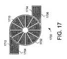
- FIG. 17is a schematic view of a proximity sensor device illustrating an electrode configuration in accordance with embodiments of the invention.
- This distancemay be on the order of less than a millimeter, millimeters, centimeters, or more, and may vary significantly with the type of position sensing technology used and the accuracy desired. Accordingly, the planarity, size, shape and exact locations of the particular sensing regions 118 will vary widely from embodiment to embodiment.
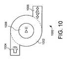
- FIG. 5illustrates a third path of object motion a user can perform on the proximity sensor device 200 to cause an adjustment of a third type.
- object motionagain originates in start tab 204 and continues in adjustment region 202 .
- the motion continuing in the adjustment region 202follows a counter-clockwise direction. This allows a user to cause a third type of adjustment.
- this third type of adjustmentwould correspond to the opposite of first type illustrated in FIG. 3 . For example, to decrease playback volume in a media player, or scrolling down a document in a PDA.
- FIG. 7illustrates a path of object motion a user can perform on the proximity sensor device 200 to cause two consecutive types of adjustment.
- object motionagain originates in start tab 204 and continues in adjustment region 202 in a counter-clockwise direction. This allows a user to cause a first type of adjustment.
- the userswitches the direction of object motion, causing the object motion to proceed in a clockwise direction. This allows the user to stop the first type of adjustment, and immediately begin a second type of adjustment, without having to lift the object and restart the gesture.
- a switchis useful a variety of situations.
- the systemcan ignore sensed levels of object motion that are above a threshold and not indicate adjustment.
- the thresholdcan be set to filter out object motion greater than what is likely to be indicative of intended input, and the proximity sensor device will not consider amounts of sensed object motion above the threshold to be indicative of object motion.
- a variety of thresholdscan be used, separately or in combination. For example, the system can require that the object motion travel a minimum distance proximate/in the sensing region before responding with adjustment, but accept object motion traveling less than that minimum distance threshold as other input. It should be noted that while object motion below the distance threshold would not generate any indications of adjustment, it could still be used to trigger other input (e.g. selection).
- the thresholdmay also alternatively be on another characteristic of the object motion, such as requiring that the speed of the object motion be beyond a certain threshold and/or below a particular threshold before generating an indication of an adjustment.
- Thresholdsmay also be combined, such that an object motion must travel a minimum distance, within a certain amount of time, and reach at least a minimum speed, before indications of adjustment will be provided. Another combination of thresholds can require that an object motion must travel no more than a maximum distance, within a certain amount of time, and not pass a maximum speed, such that the system will begin or continue indications of adjustment
- the present inventionthus provides a proximity sensor device and method that facilitates improved system usability.
- the proximity sensor device and methodprovide the ability for a user to easily select the type of adjustment inputted by the proximity sensor device using one or more start tabs.
Landscapes
- Engineering & Computer Science (AREA)
- General Engineering & Computer Science (AREA)
- Theoretical Computer Science (AREA)
- Human Computer Interaction (AREA)
- Physics & Mathematics (AREA)
- General Physics & Mathematics (AREA)
- Position Input By Displaying (AREA)
Abstract
Description
Claims (29)
Priority Applications (1)
| Application Number | Priority Date | Filing Date | Title |
|---|---|---|---|
| US11/445,875US7825797B2 (en) | 2006-06-02 | 2006-06-02 | Proximity sensor device and method with adjustment selection tabs |
Applications Claiming Priority (1)
| Application Number | Priority Date | Filing Date | Title |
|---|---|---|---|
| US11/445,875US7825797B2 (en) | 2006-06-02 | 2006-06-02 | Proximity sensor device and method with adjustment selection tabs |
Publications (2)
| Publication Number | Publication Date |
|---|---|
| US20070283263A1 US20070283263A1 (en) | 2007-12-06 |
| US7825797B2true US7825797B2 (en) | 2010-11-02 |
Family
ID=38791836
Family Applications (1)
| Application Number | Title | Priority Date | Filing Date |
|---|---|---|---|
| US11/445,875Active2028-06-27US7825797B2 (en) | 2006-06-02 | 2006-06-02 | Proximity sensor device and method with adjustment selection tabs |
Country Status (1)
| Country | Link |
|---|---|
| US (1) | US7825797B2 (en) |
Cited By (11)
| Publication number | Priority date | Publication date | Assignee | Title |
|---|---|---|---|---|
| US20090207130A1 (en)* | 2008-02-16 | 2009-08-20 | Pixart Imaging Incorporation | Input device and input method |
| US20100164871A1 (en)* | 2006-08-18 | 2010-07-01 | Kyocera Corporation | Portable Electronic Apparatus and Control Method Thereof |
| US20110231796A1 (en)* | 2010-02-16 | 2011-09-22 | Jose Manuel Vigil | Methods for navigating a touch screen device in conjunction with gestures |
| US20110294433A1 (en)* | 2010-05-28 | 2011-12-01 | Sony Corporation | Information processing apparatus, information processing system, and program |
| US20120161791A1 (en)* | 2010-12-28 | 2012-06-28 | Synaptics Incorporated | Methods and apparatus for determining input objects associated with proximity events |
| US20120306794A1 (en)* | 2006-10-11 | 2012-12-06 | Apple Inc. | Method and apparatus for implementing multiple push buttons in a user input device |
| USD683740S1 (en)* | 2011-04-28 | 2013-06-04 | Sears Brand, L.L.C. | Appliance display screen with a graphical user interface |
| US8922527B2 (en) | 2012-02-15 | 2014-12-30 | Cypress Semiconductor Corporation | Multi-purpose stylus antenna |
| USD732550S1 (en)* | 2012-12-14 | 2015-06-23 | Symantec Corporation | Display device with graphical user interface |
| US20180212620A1 (en)* | 2017-01-25 | 2018-07-26 | Pixart Imaging Inc. | Amending circuit of correcting bouncing misjudgment of a keyswitch |
| US12323159B2 (en)* | 2023-05-17 | 2025-06-03 | Cypress Semiconductor Corporation | Systems, methods, and devices for data converter management |
Families Citing this family (41)
| Publication number | Priority date | Publication date | Assignee | Title |
|---|---|---|---|---|
| US6591168B2 (en)* | 2001-08-31 | 2003-07-08 | Intellisist, Inc. | System and method for adaptable mobile user interface |
| EP1907041B1 (en) | 2005-07-11 | 2019-02-20 | Catheter Precision, Inc. | Remotely controlled catheter insertion system |
| US7880770B2 (en)* | 2006-07-28 | 2011-02-01 | Accelerated Pictures, Inc. | Camera control |
| US20080082928A1 (en)* | 2006-09-29 | 2008-04-03 | Sbc Knowledge Ventures, L.P. | Method for viewing information in a communication device |
| US20080262847A1 (en)* | 2007-04-19 | 2008-10-23 | International Business Machines Corporation | User positionable audio anchors for directional audio playback from voice-enabled interfaces |
| US9171454B2 (en) | 2007-11-14 | 2015-10-27 | Microsoft Technology Licensing, Llc | Magic wand |
| EP2071433A3 (en)* | 2007-12-12 | 2012-05-30 | Advanced Digital Broadcast S.A. | User interface for selecting and controlling plurality of parameters and method for selecting and controlling plurality of parameters |
| TWI368161B (en)* | 2007-12-21 | 2012-07-11 | Htc Corp | Electronic apparatus and input interface thereof |
| US8986246B2 (en) | 2008-01-16 | 2015-03-24 | Catheter Robotics Inc. | Remotely controlled catheter insertion system |
| WO2009092059A2 (en) | 2008-01-16 | 2009-07-23 | Catheter Robotics, Inc. | Remotely controlled catheter insertion system |
| US9211160B2 (en) | 2008-01-16 | 2015-12-15 | Luiz Geraldo Pivotto | Remotely controlled catheter insertion system with automatic control system |
| US8740840B2 (en)* | 2008-01-16 | 2014-06-03 | Catheter Robotics Inc. | Remotely controlled catheter insertion system |
| US8952894B2 (en) | 2008-05-12 | 2015-02-10 | Microsoft Technology Licensing, Llc | Computer vision-based multi-touch sensing using infrared lasers |
| JP2009288882A (en)* | 2008-05-27 | 2009-12-10 | Ntt Docomo Inc | Mobile terminal and information display method |
| US20090327974A1 (en)* | 2008-06-26 | 2009-12-31 | Microsoft Corporation | User interface for gestural control |
| US20100031202A1 (en)* | 2008-08-04 | 2010-02-04 | Microsoft Corporation | User-defined gesture set for surface computing |
| US8847739B2 (en) | 2008-08-04 | 2014-09-30 | Microsoft Corporation | Fusing RFID and vision for surface object tracking |
| US8516397B2 (en)* | 2008-10-27 | 2013-08-20 | Verizon Patent And Licensing Inc. | Proximity interface apparatuses, systems, and methods |
| US8154529B2 (en)* | 2009-05-14 | 2012-04-10 | Atmel Corporation | Two-dimensional touch sensors |
| US8884872B2 (en)* | 2009-11-20 | 2014-11-11 | Nuance Communications, Inc. | Gesture-based repetition of key activations on a virtual keyboard |
| US9019201B2 (en)* | 2010-01-08 | 2015-04-28 | Microsoft Technology Licensing, Llc | Evolving universal gesture sets |
| JP2011150413A (en) | 2010-01-19 | 2011-08-04 | Sony Corp | Information processing apparatus, method and program for inputting operation |
| EP2381351B1 (en)* | 2010-04-20 | 2017-12-06 | BlackBerry Limited | Portable electronic device having touch-sensitive display with a variable repeat control mode. |
| US20120161788A1 (en)* | 2010-07-27 | 2012-06-28 | Alion Science And Technology | Magnetic effects sensor, a resistor and method of implementing same |
| JP5572851B1 (en)* | 2013-02-26 | 2014-08-20 | パナソニック インテレクチュアル プロパティ コーポレーション オブ アメリカ | Electronics |
| US9533121B2 (en) | 2013-02-26 | 2017-01-03 | Catheter Precision, Inc. | Components and methods for accommodating guidewire catheters on a catheter controller system |
| US9910579B2 (en)* | 2013-04-15 | 2018-03-06 | Microsoft Technology Licensing, Llc | Detection of pan and scaling during multi-finger touch interactions |
| US9504919B2 (en)* | 2013-05-31 | 2016-11-29 | Cadillac Jack, Inc. | Vertical and horizontal perception audio for a gaming device |
| US9993614B2 (en) | 2013-08-27 | 2018-06-12 | Catheter Precision, Inc. | Components for multiple axis control of a catheter in a catheter positioning system |
| US9724493B2 (en) | 2013-08-27 | 2017-08-08 | Catheter Precision, Inc. | Components and methods for balancing a catheter controller system with a counterweight |
| US9750577B2 (en) | 2013-09-06 | 2017-09-05 | Catheter Precision, Inc. | Single hand operated remote controller for remote catheter positioning system |
| US9999751B2 (en) | 2013-09-06 | 2018-06-19 | Catheter Precision, Inc. | Adjustable nose cone for a catheter positioning system |
| US9700698B2 (en) | 2013-09-27 | 2017-07-11 | Catheter Precision, Inc. | Components and methods for a catheter positioning system with a spreader and track |
| US9795764B2 (en) | 2013-09-27 | 2017-10-24 | Catheter Precision, Inc. | Remote catheter positioning system with hoop drive assembly |
| USD771112S1 (en)* | 2014-06-01 | 2016-11-08 | Apple Inc. | Display screen or portion thereof with graphical user interface |
| US9936195B2 (en)* | 2014-11-06 | 2018-04-03 | Intel Corporation | Calibration for eye tracking systems |
| US9612664B2 (en)* | 2014-12-01 | 2017-04-04 | Logitech Europe S.A. | Keyboard with touch sensitive element |
| USD760746S1 (en) | 2015-06-04 | 2016-07-05 | Apple Inc. | Display screen or portion thereof with animated graphical user interface |
| USD843442S1 (en) | 2017-09-10 | 2019-03-19 | Apple Inc. | Type font |
| USD902221S1 (en) | 2019-02-01 | 2020-11-17 | Apple Inc. | Electronic device with animated graphical user interface |
| USD900871S1 (en) | 2019-02-04 | 2020-11-03 | Apple Inc. | Electronic device with animated graphical user interface |
Citations (101)
| Publication number | Priority date | Publication date | Assignee | Title |
|---|---|---|---|---|
| US3234512A (en) | 1961-03-09 | 1966-02-08 | Monroe Int | Keying method and apparatus |
| US3478220A (en) | 1966-05-11 | 1969-11-11 | Us Navy | Electro-optic cursor manipulator with associated logic circuitry |
| US4103252A (en) | 1976-11-26 | 1978-07-25 | Xerox Corporation | Capacitive touch-activated transducer system including a plurality of oscillators |
| US4110749A (en) | 1977-05-06 | 1978-08-29 | Tektronix, Inc. | Touch display to digital encoding system |
| US4177421A (en) | 1978-02-27 | 1979-12-04 | Xerox Corporation | Capacitive transducer |
| GB2050621A (en) | 1979-05-07 | 1981-01-07 | Gen Electric | Capacitive Touch Control and Display |
| US4246452A (en) | 1979-01-05 | 1981-01-20 | Mattel, Inc. | Switch apparatus |
| US4386346A (en) | 1981-03-27 | 1983-05-31 | International Business Machines Corporation | Cursor controller |
| JPS59114628A (en) | 1982-12-21 | 1984-07-02 | Matsushita Electric Ind Co Ltd | Key input device for cursor movement |
| JPS59119406A (en) | 1982-12-27 | 1984-07-10 | Panafacom Ltd | Coordinate input device |
| US4550221A (en) | 1983-10-07 | 1985-10-29 | Scott Mabusth | Touch sensitive control device |
| US4571149A (en) | 1983-04-14 | 1986-02-18 | Westinghouse Electric Corp. | General purpose orthogonal axes manipulator system |
| US4595913A (en) | 1983-02-10 | 1986-06-17 | Pie Associates | Capacitor touch activated switching system |
| EP0226716A2 (en) | 1985-09-16 | 1987-07-01 | Hewlett-Packard Company | Capacitive position transducer system |
| JPS6373415A (en) | 1986-09-17 | 1988-04-04 | Fujitsu Ltd | Coordinate input device |
| US4736191A (en) | 1985-08-02 | 1988-04-05 | Karl E. Matzke | Touch activated control method and apparatus |
| US4758830A (en) | 1984-10-25 | 1988-07-19 | Ti Corporate Services Limited | Switch/display units |
| US4777328A (en) | 1987-05-13 | 1988-10-11 | Elographics, Inc. | Circular electrographic touch sensor with orthogonal fields and linear response |
| US4951036A (en) | 1988-08-04 | 1990-08-21 | The Grass Valley Group, Inc. | Touchpad jogger |
| US5159159A (en) | 1990-12-07 | 1992-10-27 | Asher David J | Touch sensor and controller |
| US5272470A (en)* | 1991-10-10 | 1993-12-21 | International Business Machines Corporation | Apparatus and method for reducing system overhead while inking strokes in a finger or stylus-based input device of a data processing system |
| US5305017A (en) | 1989-08-16 | 1994-04-19 | Gerpheide George E | Methods and apparatus for data input |
| WO1994017494A2 (en) | 1993-01-19 | 1994-08-04 | CARRIERE TECHNICAL INDUSTRIES, a division of DERLAN MANUFACTURING INC. | Data input device |
| JPH06243253A (en) | 1993-02-15 | 1994-09-02 | Matsushita Electric Ind Co Ltd | Circular object matter detecting device |
| FR2702292A1 (en) | 1993-03-03 | 1994-09-09 | Battarel Claude | Static control of a cursor in speed and direction. |
| JPH075969A (en) | 1991-11-01 | 1995-01-10 | Hitachi Ltd | Input device and data processing system using the same |
| US5392388A (en) | 1992-12-04 | 1995-02-21 | International Business Machines Corporation | Method and system for viewing graphic images in a data processing system |
| JPH07121291A (en) | 1993-10-25 | 1995-05-12 | Toshiba Corp | Numerical input control device and method |
| US5432531A (en) | 1990-12-14 | 1995-07-11 | International Business Machines Corporation | Coordinate processor for a computer system having a pointing device |
| US5438331A (en) | 1992-08-21 | 1995-08-01 | Gilligan; Federico G. | Computer keyboard with dial for entering repetitive data and commands |
| US5452413A (en) | 1992-12-18 | 1995-09-19 | International Business Machines Corporation | Method and system for manipulating wide-angle images |
| US5453761A (en) | 1990-06-18 | 1995-09-26 | Sony Corporation | Information processing apparatus |
| US5455906A (en) | 1992-05-29 | 1995-10-03 | Hitachi Software Engineering Co., Ltd. | Electronic board system |
| US5485171A (en) | 1991-10-04 | 1996-01-16 | Micromed Systems, Inc. | Hand held computer input apparatus and method |
| US5491706A (en) | 1993-04-07 | 1996-02-13 | Sharp Kabushiki Kaisha | Display-integrated type tablet device capable of detecting correct coordinates at a tip end of a detection pen by detecting external noise |
| US5508703A (en) | 1992-09-14 | 1996-04-16 | Smk Corporation | Membrane switch having a rotary motion detection function |
| US5518078A (en) | 1991-11-08 | 1996-05-21 | Sharp Kabushiki Kaisha | Coordinates input device |
| US5543590A (en) | 1992-06-08 | 1996-08-06 | Synaptics, Incorporated | Object position detector with edge motion feature |
| US5543591A (en) | 1992-06-08 | 1996-08-06 | Synaptics, Incorporated | Object position detector with edge motion feature and gesture recognition |
| US5546106A (en) | 1993-08-20 | 1996-08-13 | U.S. Philips Corporation | Interactive image display device with cursor control |
| US5565658A (en) | 1992-07-13 | 1996-10-15 | Cirque Corporation | Capacitance-based proximity with interference rejection apparatus and methods |
| US5633660A (en) | 1993-02-12 | 1997-05-27 | Trinitech Systems Inc. | Integrated touch screen input device |
| US5650597A (en) | 1995-01-20 | 1997-07-22 | Dynapro Systems, Inc. | Capacitive touch sensor |
| JPH09230993A (en) | 1996-02-20 | 1997-09-05 | Sharp Corp | Jog dial simulation input device |
| US5736865A (en) | 1996-09-16 | 1998-04-07 | Delco Electronics Corporation | Capacitive rotary position encoder |
| US5748185A (en) | 1996-07-03 | 1998-05-05 | Stratos Product Development Group | Touchpad with scroll and pan regions |
| US5781178A (en) | 1996-01-03 | 1998-07-14 | General Electric Company | Wireless remote input for electronic equipment |
| US5808602A (en) | 1996-03-15 | 1998-09-15 | Compaq Computer Corporation | Rotary cursor positioning apparatus |
| US5825352A (en) | 1996-01-04 | 1998-10-20 | Logitech, Inc. | Multiple fingers contact sensing method for emulating mouse buttons and mouse operations on a touch sensor pad |
| EP0880091A2 (en) | 1997-05-21 | 1998-11-25 | Nokia Mobile Phones Ltd. | A method and an arrangement for scrolling information presented on a display of a mobile station |
| US5844506A (en) | 1994-04-05 | 1998-12-01 | Binstead; Ronald Peter | Multiple input proximity detector and touchpad system |
| US5861875A (en) | 1992-07-13 | 1999-01-19 | Cirque Corporation | Methods and apparatus for data input |
| US5880717A (en)* | 1997-03-14 | 1999-03-09 | Tritech Microelectronics International, Ltd. | Automatic cursor motion control for a touchpad mouse |
| JPH11105646A (en) | 1997-10-06 | 1999-04-20 | Fuji Heavy Ind Ltd | Concentrated control unit for on-vehicle equipment |
| US5907472A (en) | 1994-10-07 | 1999-05-25 | Maxwell Laboratories, Inc. | Multi-electrode double layer capacitor having single electrolyte seal and aluminum-impregnated carbon cloth electrodes |
| US5914465A (en) | 1992-06-08 | 1999-06-22 | Synaptics, Inc. | Object position detector |
| JPH11194883A (en) | 1998-01-06 | 1999-07-21 | Poseidon Technical Systems:Kk | Touch operation type computer |
| JPH11194863A (en) | 1998-01-06 | 1999-07-21 | Poseidon Technical Systems:Kk | Touch input detecting method and touch input detector |
| US5933102A (en) | 1997-09-24 | 1999-08-03 | Tanisys Technology, Inc. | Capacitive sensitive switch method and system |
| US5943052A (en) | 1997-08-12 | 1999-08-24 | Synaptics, Incorporated | Method and apparatus for scroll bar control |
| JPH11232026A (en) | 1998-02-16 | 1999-08-27 | Canon Inc | Image processing device |
| US6057826A (en) | 1993-09-02 | 2000-05-02 | Sextant Avionique | Method and device for managing the relative displacement of a cursor in relation to the image displayed on a viewing device |
| US6094197A (en)* | 1993-12-21 | 2000-07-25 | Xerox Corporation | Graphical keyboard |
| US6163312A (en) | 1997-12-22 | 2000-12-19 | Sony Corporation | Portable radio information terminal, screen scroll method, recording medium and microcomputer |
| CA2316104A1 (en) | 1999-08-25 | 2001-02-25 | Swatch Ag | Watch including a contactless control device for a computer cursor |
| US6259432B1 (en) | 1997-08-11 | 2001-07-10 | International Business Machines Corporation | Information processing apparatus for improved intuitive scrolling utilizing an enhanced cursor |
| US6300939B1 (en) | 1997-10-23 | 2001-10-09 | Nokia Mobile Phones Ltd. | Input device |
| WO2001078238A1 (en) | 2000-04-11 | 2001-10-18 | Cirque Corporation | Efficient entry of characters into a portable information appliance |
| USD457149S1 (en) | 2000-02-23 | 2002-05-14 | Detewe Ag & Co. | Mobile telephone |
| US6424338B1 (en) | 1999-09-30 | 2002-07-23 | Gateway, Inc. | Speed zone touchpad |
| US6459424B1 (en) | 1999-08-10 | 2002-10-01 | Hewlett-Packard Company | Touch-sensitive input screen having regional sensitivity and resolution properties |
| US6473069B1 (en) | 1995-11-13 | 2002-10-29 | Cirque Corporation | Apparatus and method for tactile feedback from input device |
| USD469109S1 (en) | 2001-10-22 | 2003-01-21 | Apple Computer, Inc. | Media player |
| US20030043113A1 (en)* | 2001-09-04 | 2003-03-06 | Alps Electric Co., Ltd. | Coordinates input apparatus having divided coordinates input surface |
| US20030048262A1 (en) | 1999-05-24 | 2003-03-13 | Charles Wu | Method and apparatus for navigation, text input and phone dialing |
| US20030076301A1 (en) | 2001-10-22 | 2003-04-24 | Apple Computer, Inc. | Method and apparatus for accelerated scrolling |
| US20030076306A1 (en)* | 2001-10-22 | 2003-04-24 | Zadesky Stephen Paul | Touch pad handheld device |
| US20030076303A1 (en) | 2001-10-22 | 2003-04-24 | Apple Computers, Inc. | Mouse having a rotary dial |
| US20030095096A1 (en) | 2001-10-22 | 2003-05-22 | Apple Computer, Inc. | Method and apparatus for use of rotational user inputs |
| US6570557B1 (en) | 2001-02-10 | 2003-05-27 | Finger Works, Inc. | Multi-touch system and method for emulating modifier keys via fingertip chords |
| US20030164818A1 (en) | 2000-08-11 | 2003-09-04 | Koninklijke Philips Electronics N.V. | Image control system |
| US6639584B1 (en) | 1999-07-06 | 2003-10-28 | Chuang Li | Methods and apparatus for controlling a portable electronic device using a touchpad |
| US20040021694A1 (en) | 2002-08-01 | 2004-02-05 | Apple Computer, Inc. | Mode activated scrolling |
| US20040055446A1 (en) | 2002-07-30 | 2004-03-25 | Apple Computer, Inc. | Graphical user interface and methods of use thereof in a multimedia player |
| JP2004511849A (en) | 2000-09-22 | 2004-04-15 | バダルネー、ジアド | Means for a handheld functional device |
| US6757002B1 (en)* | 1999-11-04 | 2004-06-29 | Hewlett-Packard Development Company, L.P. | Track pad pointing device with areas of specialized function |
| US6771280B2 (en) | 2002-02-06 | 2004-08-03 | Matsushita Electric Industrial Co., Ltd. | Apparatus and method for data-processing |
| US6781576B2 (en) | 2001-03-14 | 2004-08-24 | Sensation, Inc. | Wireless input apparatus and method using a three-dimensional pointing device |
| US6788288B2 (en) | 2000-09-11 | 2004-09-07 | Matsushita Electric Industrial Co., Ltd. | Coordinate input device and portable information apparatus equipped with coordinate input device |
| US20040252109A1 (en) | 2002-04-11 | 2004-12-16 | Synaptics, Inc. | Closed-loop sensor on a solid-state object position detector |
| US20050052425A1 (en) | 2003-08-18 | 2005-03-10 | Zadesky Stephen Paul | Movable touch pad with added functionality |
| US20050078182A1 (en)* | 2003-09-29 | 2005-04-14 | Lipsky Scott E. | Method and system for specifying a pan path |
| US20050168489A1 (en)* | 2004-01-29 | 2005-08-04 | Synaptics Incorporated | Method and apparatus for producing one-dimensional signals with a two-dimensional pointing device |
| US20060028454A1 (en) | 2004-08-04 | 2006-02-09 | Interlink Electronics, Inc. | Multifunctional scroll sensor |
| US20060033721A1 (en)* | 2004-04-23 | 2006-02-16 | Richard Woolley | Method for scrolling and edge motion on a touchpad |
| US7031886B1 (en) | 2004-12-14 | 2006-04-18 | Synaptics Incorporated | Methods and systems for detecting noise in a position sensor using minor shifts in sensing frequency |
| US20060161871A1 (en)* | 2004-07-30 | 2006-07-20 | Apple Computer, Inc. | Proximity detector in handheld device |
| US20070097088A1 (en) | 2005-10-31 | 2007-05-03 | Battles Amy E | Imaging device scrolling touch pad with tap points |
| US20070097089A1 (en) | 2005-10-31 | 2007-05-03 | Battles Amy E | Imaging device control using touch pad |
| US20070097090A1 (en) | 2005-10-31 | 2007-05-03 | Battles Amy E | Digital camera user interface |
| US7233316B2 (en) | 2003-05-01 | 2007-06-19 | Thomson Licensing | Multimedia user interface |
- 2006
- 2006-06-02USUS11/445,875patent/US7825797B2/enactiveActive
Patent Citations (111)
| Publication number | Priority date | Publication date | Assignee | Title |
|---|---|---|---|---|
| US3234512A (en) | 1961-03-09 | 1966-02-08 | Monroe Int | Keying method and apparatus |
| US3478220A (en) | 1966-05-11 | 1969-11-11 | Us Navy | Electro-optic cursor manipulator with associated logic circuitry |
| US4103252A (en) | 1976-11-26 | 1978-07-25 | Xerox Corporation | Capacitive touch-activated transducer system including a plurality of oscillators |
| US4110749A (en) | 1977-05-06 | 1978-08-29 | Tektronix, Inc. | Touch display to digital encoding system |
| US4177421A (en) | 1978-02-27 | 1979-12-04 | Xerox Corporation | Capacitive transducer |
| US4264903A (en) | 1978-06-12 | 1981-04-28 | General Electric Company | Capacitive touch control and display |
| US4246452A (en) | 1979-01-05 | 1981-01-20 | Mattel, Inc. | Switch apparatus |
| GB2050621A (en) | 1979-05-07 | 1981-01-07 | Gen Electric | Capacitive Touch Control and Display |
| US4386346A (en) | 1981-03-27 | 1983-05-31 | International Business Machines Corporation | Cursor controller |
| JPS59114628A (en) | 1982-12-21 | 1984-07-02 | Matsushita Electric Ind Co Ltd | Key input device for cursor movement |
| JPS59119406A (en) | 1982-12-27 | 1984-07-10 | Panafacom Ltd | Coordinate input device |
| US4595913A (en) | 1983-02-10 | 1986-06-17 | Pie Associates | Capacitor touch activated switching system |
| US4571149A (en) | 1983-04-14 | 1986-02-18 | Westinghouse Electric Corp. | General purpose orthogonal axes manipulator system |
| US4550221A (en) | 1983-10-07 | 1985-10-29 | Scott Mabusth | Touch sensitive control device |
| US4758830A (en) | 1984-10-25 | 1988-07-19 | Ti Corporate Services Limited | Switch/display units |
| US4736191A (en) | 1985-08-02 | 1988-04-05 | Karl E. Matzke | Touch activated control method and apparatus |
| EP0226716A2 (en) | 1985-09-16 | 1987-07-01 | Hewlett-Packard Company | Capacitive position transducer system |
| JPS6373415A (en) | 1986-09-17 | 1988-04-04 | Fujitsu Ltd | Coordinate input device |
| US4777328A (en) | 1987-05-13 | 1988-10-11 | Elographics, Inc. | Circular electrographic touch sensor with orthogonal fields and linear response |
| US4951036A (en) | 1988-08-04 | 1990-08-21 | The Grass Valley Group, Inc. | Touchpad jogger |
| US5305017A (en) | 1989-08-16 | 1994-04-19 | Gerpheide George E | Methods and apparatus for data input |
| US5453761A (en) | 1990-06-18 | 1995-09-26 | Sony Corporation | Information processing apparatus |
| US5159159A (en) | 1990-12-07 | 1992-10-27 | Asher David J | Touch sensor and controller |
| US5432531A (en) | 1990-12-14 | 1995-07-11 | International Business Machines Corporation | Coordinate processor for a computer system having a pointing device |
| US5485171A (en) | 1991-10-04 | 1996-01-16 | Micromed Systems, Inc. | Hand held computer input apparatus and method |
| US5272470A (en)* | 1991-10-10 | 1993-12-21 | International Business Machines Corporation | Apparatus and method for reducing system overhead while inking strokes in a finger or stylus-based input device of a data processing system |
| JPH075969A (en) | 1991-11-01 | 1995-01-10 | Hitachi Ltd | Input device and data processing system using the same |
| US5518078A (en) | 1991-11-08 | 1996-05-21 | Sharp Kabushiki Kaisha | Coordinates input device |
| US5455906A (en) | 1992-05-29 | 1995-10-03 | Hitachi Software Engineering Co., Ltd. | Electronic board system |
| US5543591A (en) | 1992-06-08 | 1996-08-06 | Synaptics, Incorporated | Object position detector with edge motion feature and gesture recognition |
| US5543590A (en) | 1992-06-08 | 1996-08-06 | Synaptics, Incorporated | Object position detector with edge motion feature |
| US5914465A (en) | 1992-06-08 | 1999-06-22 | Synaptics, Inc. | Object position detector |
| US5565658A (en) | 1992-07-13 | 1996-10-15 | Cirque Corporation | Capacitance-based proximity with interference rejection apparatus and methods |
| US5861875A (en) | 1992-07-13 | 1999-01-19 | Cirque Corporation | Methods and apparatus for data input |
| US5438331A (en) | 1992-08-21 | 1995-08-01 | Gilligan; Federico G. | Computer keyboard with dial for entering repetitive data and commands |
| US5508703A (en) | 1992-09-14 | 1996-04-16 | Smk Corporation | Membrane switch having a rotary motion detection function |
| US5392388A (en) | 1992-12-04 | 1995-02-21 | International Business Machines Corporation | Method and system for viewing graphic images in a data processing system |
| US5452413A (en) | 1992-12-18 | 1995-09-19 | International Business Machines Corporation | Method and system for manipulating wide-angle images |
| WO1994017494A2 (en) | 1993-01-19 | 1994-08-04 | CARRIERE TECHNICAL INDUSTRIES, a division of DERLAN MANUFACTURING INC. | Data input device |
| US5633660A (en) | 1993-02-12 | 1997-05-27 | Trinitech Systems Inc. | Integrated touch screen input device |
| JPH06243253A (en) | 1993-02-15 | 1994-09-02 | Matsushita Electric Ind Co Ltd | Circular object matter detecting device |
| FR2702292A1 (en) | 1993-03-03 | 1994-09-09 | Battarel Claude | Static control of a cursor in speed and direction. |
| US5491706A (en) | 1993-04-07 | 1996-02-13 | Sharp Kabushiki Kaisha | Display-integrated type tablet device capable of detecting correct coordinates at a tip end of a detection pen by detecting external noise |
| US5546106A (en) | 1993-08-20 | 1996-08-13 | U.S. Philips Corporation | Interactive image display device with cursor control |
| US6057826A (en) | 1993-09-02 | 2000-05-02 | Sextant Avionique | Method and device for managing the relative displacement of a cursor in relation to the image displayed on a viewing device |
| JPH07121291A (en) | 1993-10-25 | 1995-05-12 | Toshiba Corp | Numerical input control device and method |
| US6094197A (en)* | 1993-12-21 | 2000-07-25 | Xerox Corporation | Graphical keyboard |
| US6137427A (en) | 1994-04-05 | 2000-10-24 | Binstead; Ronald Peter | Multiple input proximity detector and touchpad system |
| US5844506A (en) | 1994-04-05 | 1998-12-01 | Binstead; Ronald Peter | Multiple input proximity detector and touchpad system |
| US5907472A (en) | 1994-10-07 | 1999-05-25 | Maxwell Laboratories, Inc. | Multi-electrode double layer capacitor having single electrolyte seal and aluminum-impregnated carbon cloth electrodes |
| US5650597A (en) | 1995-01-20 | 1997-07-22 | Dynapro Systems, Inc. | Capacitive touch sensor |
| US6473069B1 (en) | 1995-11-13 | 2002-10-29 | Cirque Corporation | Apparatus and method for tactile feedback from input device |
| US5781178A (en) | 1996-01-03 | 1998-07-14 | General Electric Company | Wireless remote input for electronic equipment |
| US5825352A (en) | 1996-01-04 | 1998-10-20 | Logitech, Inc. | Multiple fingers contact sensing method for emulating mouse buttons and mouse operations on a touch sensor pad |
| US5903229A (en)* | 1996-02-20 | 1999-05-11 | Sharp Kabushiki Kaisha | Jog dial emulation input device |
| JPH09230993A (en) | 1996-02-20 | 1997-09-05 | Sharp Corp | Jog dial simulation input device |
| US5808602A (en) | 1996-03-15 | 1998-09-15 | Compaq Computer Corporation | Rotary cursor positioning apparatus |
| US5748185A (en) | 1996-07-03 | 1998-05-05 | Stratos Product Development Group | Touchpad with scroll and pan regions |
| US5941122A (en) | 1996-09-16 | 1999-08-24 | Delco Electronics Corporation | Liquid level sensor incorporating a capacitive rotary position encoder |
| US5736865A (en) | 1996-09-16 | 1998-04-07 | Delco Electronics Corporation | Capacitive rotary position encoder |
| US5880717A (en)* | 1997-03-14 | 1999-03-09 | Tritech Microelectronics International, Ltd. | Automatic cursor motion control for a touchpad mouse |
| EP0880091A2 (en) | 1997-05-21 | 1998-11-25 | Nokia Mobile Phones Ltd. | A method and an arrangement for scrolling information presented on a display of a mobile station |
| US6259432B1 (en) | 1997-08-11 | 2001-07-10 | International Business Machines Corporation | Information processing apparatus for improved intuitive scrolling utilizing an enhanced cursor |
| US5943052A (en) | 1997-08-12 | 1999-08-24 | Synaptics, Incorporated | Method and apparatus for scroll bar control |
| US5933102A (en) | 1997-09-24 | 1999-08-03 | Tanisys Technology, Inc. | Capacitive sensitive switch method and system |
| JPH11105646A (en) | 1997-10-06 | 1999-04-20 | Fuji Heavy Ind Ltd | Concentrated control unit for on-vehicle equipment |
| US6300939B1 (en) | 1997-10-23 | 2001-10-09 | Nokia Mobile Phones Ltd. | Input device |
| US6163312A (en) | 1997-12-22 | 2000-12-19 | Sony Corporation | Portable radio information terminal, screen scroll method, recording medium and microcomputer |
| JPH11194863A (en) | 1998-01-06 | 1999-07-21 | Poseidon Technical Systems:Kk | Touch input detecting method and touch input detector |
| JPH11194883A (en) | 1998-01-06 | 1999-07-21 | Poseidon Technical Systems:Kk | Touch operation type computer |
| JPH11232026A (en) | 1998-02-16 | 1999-08-27 | Canon Inc | Image processing device |
| US20030048262A1 (en) | 1999-05-24 | 2003-03-13 | Charles Wu | Method and apparatus for navigation, text input and phone dialing |
| US6639584B1 (en) | 1999-07-06 | 2003-10-28 | Chuang Li | Methods and apparatus for controlling a portable electronic device using a touchpad |
| US6459424B1 (en) | 1999-08-10 | 2002-10-01 | Hewlett-Packard Company | Touch-sensitive input screen having regional sensitivity and resolution properties |
| JP2001109571A (en) | 1999-08-25 | 2001-04-20 | Swatch Ag | Timepiece including radio controller for computer cursor |
| EP1079325A1 (en) | 1999-08-25 | 2001-02-28 | Swatch Ag | Watch having a non-contact computer cursor controller |
| CA2316104A1 (en) | 1999-08-25 | 2001-02-25 | Swatch Ag | Watch including a contactless control device for a computer cursor |
| US6424338B1 (en) | 1999-09-30 | 2002-07-23 | Gateway, Inc. | Speed zone touchpad |
| US6757002B1 (en)* | 1999-11-04 | 2004-06-29 | Hewlett-Packard Development Company, L.P. | Track pad pointing device with areas of specialized function |
| USD457149S1 (en) | 2000-02-23 | 2002-05-14 | Detewe Ag & Co. | Mobile telephone |
| WO2001078238A1 (en) | 2000-04-11 | 2001-10-18 | Cirque Corporation | Efficient entry of characters into a portable information appliance |
| US20020000978A1 (en) | 2000-04-11 | 2002-01-03 | George Gerpheide | Efficient entry of characters from a large character set into a portable information appliance |
| US20030164818A1 (en) | 2000-08-11 | 2003-09-04 | Koninklijke Philips Electronics N.V. | Image control system |
| US6788288B2 (en) | 2000-09-11 | 2004-09-07 | Matsushita Electric Industrial Co., Ltd. | Coordinate input device and portable information apparatus equipped with coordinate input device |
| US20040104898A1 (en) | 2000-09-22 | 2004-06-03 | Ziad Badarneh | Means for handhold functional apparatus |
| JP2004511849A (en) | 2000-09-22 | 2004-04-15 | バダルネー、ジアド | Means for a handheld functional device |
| JP2004514203A (en) | 2000-11-08 | 2004-05-13 | コーニンクレッカ フィリップス エレクトロニクス エヌ ヴィ | Image control system |
| US6570557B1 (en) | 2001-02-10 | 2003-05-27 | Finger Works, Inc. | Multi-touch system and method for emulating modifier keys via fingertip chords |
| US6781576B2 (en) | 2001-03-14 | 2004-08-24 | Sensation, Inc. | Wireless input apparatus and method using a three-dimensional pointing device |
| US20030043113A1 (en)* | 2001-09-04 | 2003-03-06 | Alps Electric Co., Ltd. | Coordinates input apparatus having divided coordinates input surface |
| US20030095096A1 (en) | 2001-10-22 | 2003-05-22 | Apple Computer, Inc. | Method and apparatus for use of rotational user inputs |
| USD469109S1 (en) | 2001-10-22 | 2003-01-21 | Apple Computer, Inc. | Media player |
| US20030076303A1 (en) | 2001-10-22 | 2003-04-24 | Apple Computers, Inc. | Mouse having a rotary dial |
| US20030076306A1 (en)* | 2001-10-22 | 2003-04-24 | Zadesky Stephen Paul | Touch pad handheld device |
| US20030076301A1 (en) | 2001-10-22 | 2003-04-24 | Apple Computer, Inc. | Method and apparatus for accelerated scrolling |
| USD472245S1 (en) | 2001-10-22 | 2003-03-25 | Apple Computer, Inc. | Media player |
| US6771280B2 (en) | 2002-02-06 | 2004-08-03 | Matsushita Electric Industrial Co., Ltd. | Apparatus and method for data-processing |
| US20040252109A1 (en) | 2002-04-11 | 2004-12-16 | Synaptics, Inc. | Closed-loop sensor on a solid-state object position detector |
| US20040055446A1 (en) | 2002-07-30 | 2004-03-25 | Apple Computer, Inc. | Graphical user interface and methods of use thereof in a multimedia player |
| US20040021694A1 (en) | 2002-08-01 | 2004-02-05 | Apple Computer, Inc. | Mode activated scrolling |
| US7233316B2 (en) | 2003-05-01 | 2007-06-19 | Thomson Licensing | Multimedia user interface |
| US20050052425A1 (en) | 2003-08-18 | 2005-03-10 | Zadesky Stephen Paul | Movable touch pad with added functionality |
| US20050078182A1 (en)* | 2003-09-29 | 2005-04-14 | Lipsky Scott E. | Method and system for specifying a pan path |
| US20050168489A1 (en)* | 2004-01-29 | 2005-08-04 | Synaptics Incorporated | Method and apparatus for producing one-dimensional signals with a two-dimensional pointing device |
| US20060033721A1 (en)* | 2004-04-23 | 2006-02-16 | Richard Woolley | Method for scrolling and edge motion on a touchpad |
| US20060161871A1 (en)* | 2004-07-30 | 2006-07-20 | Apple Computer, Inc. | Proximity detector in handheld device |
| US20060028454A1 (en) | 2004-08-04 | 2006-02-09 | Interlink Electronics, Inc. | Multifunctional scroll sensor |
| US7031886B1 (en) | 2004-12-14 | 2006-04-18 | Synaptics Incorporated | Methods and systems for detecting noise in a position sensor using minor shifts in sensing frequency |
| US20070097088A1 (en) | 2005-10-31 | 2007-05-03 | Battles Amy E | Imaging device scrolling touch pad with tap points |
| US20070097089A1 (en) | 2005-10-31 | 2007-05-03 | Battles Amy E | Imaging device control using touch pad |
| US20070097090A1 (en) | 2005-10-31 | 2007-05-03 | Battles Amy E | Digital camera user interface |
Non-Patent Citations (5)
| Title |
|---|
| European Search Report 03746701.6 dated Jun. 9, 2010. |
| Evans et al.; "Tablet-Based Valuators that Provide One, Two, or Three Degrees of Freedom", Computer Graphics, vol. 15, No. 3; Aug. 1981; pp. 91-97. |
| Friedlan et al.; "Bullseye! When Fitts' Law Doesn't Fit"; CHI 98; Apr. 18-23, 1998; pp. 257-264; Los Angeles, California USA. |
| Kobayashi et al.; "Dynamic Soundscape: Mapping Time to Space for Audio Browsing"; CHI 97; Mar. 22-27, 1997; pp. 194-201; Atlanta, Georgia USA. |
| Smith et al.; "Generalized and Stationary Scrolling"; CHI Letters vol. 1,1; 1999; pp. 1-9; Asheville, North Carolina USA. |
Cited By (23)
| Publication number | Priority date | Publication date | Assignee | Title |
|---|---|---|---|---|
| US20100164871A1 (en)* | 2006-08-18 | 2010-07-01 | Kyocera Corporation | Portable Electronic Apparatus and Control Method Thereof |
| US8704771B2 (en)* | 2006-08-18 | 2014-04-22 | Kyocera Corporation | Portable electronic apparatus and control method thereof |
| US20120306794A1 (en)* | 2006-10-11 | 2012-12-06 | Apple Inc. | Method and apparatus for implementing multiple push buttons in a user input device |
| US20110134077A1 (en)* | 2008-02-16 | 2011-06-09 | Pixart Imaging Incorporation | Input Device and Input Method |
| US20090207130A1 (en)* | 2008-02-16 | 2009-08-20 | Pixart Imaging Incorporation | Input device and input method |
| US20110231796A1 (en)* | 2010-02-16 | 2011-09-22 | Jose Manuel Vigil | Methods for navigating a touch screen device in conjunction with gestures |
| US20180074774A1 (en)* | 2010-05-28 | 2018-03-15 | Sony Corporation | Information processing apparatus, information processing system, and program |
| US20190196772A1 (en)* | 2010-05-28 | 2019-06-27 | Sony Corporation | Information processing apparatus, information processing system, and program |
| US8750802B2 (en)* | 2010-05-28 | 2014-06-10 | Sony Corporation | Information processing apparatus, information processing system, and program |
| US20140240199A1 (en)* | 2010-05-28 | 2014-08-28 | Sony Corporation | Information processing apparatus, information processing system, and program |
| US11068222B2 (en)* | 2010-05-28 | 2021-07-20 | Sony Corporation | Information processing apparatus and information processing system |
| US9400628B2 (en)* | 2010-05-28 | 2016-07-26 | Sony Corporation | Information processing apparatus, information processing system, and program |
| US9836265B2 (en)* | 2010-05-28 | 2017-12-05 | Sony Corporation | Information processing apparatus, information processing system, and program |
| US20110294433A1 (en)* | 2010-05-28 | 2011-12-01 | Sony Corporation | Information processing apparatus, information processing system, and program |
| US10684812B2 (en)* | 2010-05-28 | 2020-06-16 | Sony Corporation | Information processing apparatus and information processing system |
| US10255015B2 (en)* | 2010-05-28 | 2019-04-09 | Sony Corporation | Information processing apparatus and information processing system |
| US20120161791A1 (en)* | 2010-12-28 | 2012-06-28 | Synaptics Incorporated | Methods and apparatus for determining input objects associated with proximity events |
| USD683740S1 (en)* | 2011-04-28 | 2013-06-04 | Sears Brand, L.L.C. | Appliance display screen with a graphical user interface |
| US8922527B2 (en) | 2012-02-15 | 2014-12-30 | Cypress Semiconductor Corporation | Multi-purpose stylus antenna |
| USD732550S1 (en)* | 2012-12-14 | 2015-06-23 | Symantec Corporation | Display device with graphical user interface |
| US10659077B2 (en)* | 2017-01-25 | 2020-05-19 | Pixart Imaging Inc. | Amending circuit of correcting bouncing misjudgment of a keyswitch |
| US20180212620A1 (en)* | 2017-01-25 | 2018-07-26 | Pixart Imaging Inc. | Amending circuit of correcting bouncing misjudgment of a keyswitch |
| US12323159B2 (en)* | 2023-05-17 | 2025-06-03 | Cypress Semiconductor Corporation | Systems, methods, and devices for data converter management |
Also Published As
| Publication number | Publication date |
|---|---|
| US20070283263A1 (en) | 2007-12-06 |
Similar Documents
| Publication | Publication Date | Title |
|---|---|---|
| US7825797B2 (en) | Proximity sensor device and method with adjustment selection tabs | |
| US20070262951A1 (en) | Proximity sensor device and method with improved indication of adjustment | |
| US8139028B2 (en) | Proximity sensor and method for indicating extended interface results | |
| US11886699B2 (en) | Selective rejection of touch contacts in an edge region of a touch surface | |
| US7884807B2 (en) | Proximity sensor and method for indicating a display orientation change | |
| US8692767B2 (en) | Input device and method for virtual trackball operation | |
| KR101096358B1 (en) | Apparatus and method for selective input signal rejection and correction | |
| US8947364B2 (en) | Proximity sensor device and method with activation confirmation | |
| US9395905B2 (en) | Graphical scroll wheel | |
| US8174504B2 (en) | Input device and method for adjusting a parameter of an electronic system | |
| US20090289902A1 (en) | Proximity sensor device and method with subregion based swipethrough data entry | |
| US20090288889A1 (en) | Proximity sensor device and method with swipethrough data entry | |
| AU2013205165B2 (en) | Interpreting touch contacts on a touch surface | |
| AU2015271962B2 (en) | Interpreting touch contacts on a touch surface |
Legal Events
| Date | Code | Title | Description |
|---|---|---|---|
| AS | Assignment | Owner name:SYNAPTICS INCORPORATED, CALIFORNIA Free format text:ASSIGNMENT OF ASSIGNORS INTEREST;ASSIGNORS:LE, THUY T.B.;ZAWDE, FIDEL;FELAND, JOHN;AND OTHERS;REEL/FRAME:017966/0126 Effective date:20060601 | |
| STCF | Information on status: patent grant | Free format text:PATENTED CASE | |
| FPAY | Fee payment | Year of fee payment:4 | |
| AS | Assignment | Owner name:WELLS FARGO BANK, NATIONAL ASSOCIATION, NORTH CARO Free format text:SECURITY INTEREST;ASSIGNOR:SYNAPTICS INCORPORATED;REEL/FRAME:033888/0851 Effective date:20140930 | |
| AS | Assignment | Owner name:WELLS FARGO BANK, NATIONAL ASSOCIATION, NORTH CAROLINA Free format text:SECURITY INTEREST;ASSIGNOR:SYNAPTICS INCORPORATED;REEL/FRAME:044037/0896 Effective date:20170927 Owner name:WELLS FARGO BANK, NATIONAL ASSOCIATION, NORTH CARO Free format text:SECURITY INTEREST;ASSIGNOR:SYNAPTICS INCORPORATED;REEL/FRAME:044037/0896 Effective date:20170927 | |
| MAFP | Maintenance fee payment | Free format text:PAYMENT OF MAINTENANCE FEE, 8TH YEAR, LARGE ENTITY (ORIGINAL EVENT CODE: M1552) Year of fee payment:8 | |
| AS | Assignment | Owner name:SYNAPTICS INCORPORATED, CALIFORNIA Free format text:RELEASE BY SECURED PARTY;ASSIGNOR:WELLS FARGO BANK, NATIONAL ASSOCIATION;REEL/FRAME:050206/0252 Effective date:20190805 | |
| AS | Assignment | Owner name:WACOM CO., LTD., JAPAN Free format text:ASSIGNMENT OF ASSIGNORS INTEREST;ASSIGNOR:SYNAPTICS INCORPORATED;REEL/FRAME:050229/0145 Effective date:20190827 | |
| MAFP | Maintenance fee payment | Free format text:PAYMENT OF MAINTENANCE FEE, 12TH YEAR, LARGE ENTITY (ORIGINAL EVENT CODE: M1553); ENTITY STATUS OF PATENT OWNER: LARGE ENTITY Year of fee payment:12 |