US7824470B2 - Method for enhancing mass transport in fuel deoxygenation systems - Google Patents
Method for enhancing mass transport in fuel deoxygenation systemsDownload PDFInfo
- Publication number
- US7824470B2 US7824470B2US11/334,126US33412606AUS7824470B2US 7824470 B2US7824470 B2US 7824470B2US 33412606 AUS33412606 AUS 33412606AUS 7824470 B2US7824470 B2US 7824470B2
- Authority
- US
- United States
- Prior art keywords
- flow
- fuel
- multitude
- permeable membrane
- impingement elements
- Prior art date
- Legal status (The legal status is an assumption and is not a legal conclusion. Google has not performed a legal analysis and makes no representation as to the accuracy of the status listed.)
- Active, expires
Links
Images


Classifications
- B—PERFORMING OPERATIONS; TRANSPORTING
- B01—PHYSICAL OR CHEMICAL PROCESSES OR APPARATUS IN GENERAL
- B01D—SEPARATION
- B01D19/00—Degasification of liquids
- B—PERFORMING OPERATIONS; TRANSPORTING
- B01—PHYSICAL OR CHEMICAL PROCESSES OR APPARATUS IN GENERAL
- B01D—SEPARATION
- B01D19/00—Degasification of liquids
- B01D19/0042—Degasification of liquids modifying the liquid flow
- B—PERFORMING OPERATIONS; TRANSPORTING
- B01—PHYSICAL OR CHEMICAL PROCESSES OR APPARATUS IN GENERAL
- B01D—SEPARATION
- B01D19/00—Degasification of liquids
- B01D19/0031—Degasification of liquids by filtration
- B—PERFORMING OPERATIONS; TRANSPORTING
- B01—PHYSICAL OR CHEMICAL PROCESSES OR APPARATUS IN GENERAL
- B01D—SEPARATION
- B01D61/00—Processes of separation using semi-permeable membranes, e.g. dialysis, osmosis or ultrafiltration; Apparatus, accessories or auxiliary operations specially adapted therefor
- F—MECHANICAL ENGINEERING; LIGHTING; HEATING; WEAPONS; BLASTING
- F23—COMBUSTION APPARATUS; COMBUSTION PROCESSES
- F23K—FEEDING FUEL TO COMBUSTION APPARATUS
- F23K2900/00—Special features of, or arrangements for fuel supplies
- F23K2900/05082—Removing gaseous substances from liquid fuel line, e.g. oxygen
Definitions
- the present inventionrelates to liquid degassing, and more particularly to a multitude of flow impingement elements which are interleaved to provide a fuel channel with intricate two-dimensional flow characteristics that enhance mixing and oxygen transport.
- Jet fuelis often utilized in aircraft as a coolant for various aircraft systems.
- the presence of dissolved oxygen in hydrocarbon jet fuelsmay be objectionable because the oxygen supports oxidation reactions that yield undesirable by-products.
- Solution of air in jet fuelresults in an approximately 70 ppm oxygen concentration at the equilibrium saturation condition.
- aerated fuelis heated between approximately 300° F. and 850° F. the dissolved oxygen initiates free radical reactions of the fuel resulting in deposits commonly referred to as “coke” or “coking.” Coke may be detrimental to the fuel system and may inhibit combustion. The formation of such deposits may impair the normal functioning of a fuel system, either with respect to an intended heat exchange function or the efficient injection of fuel.
- One Fuel Stabilization Unitintended for use in aircraft removes oxygen from jet fuel by producing an oxygen partial pressure gradient across a membrane permeable to oxygen.
- the FSUincludes a plurality of flow plates sandwiched between permeable membranes and porous substrate plates within a housing. Each flow plate defines a portion of the fuel passage and the porous plate backed permeable membranes define the remaining portions of the fuel passages.
- planar flow platesutilize flow impingement elements to enhance contact between fuel flow and the oxygen permeable membrane to increase mass transport of dissolved oxygen.
- Design of the flow impingement elementsposes relatively complicated fluid dynamic issues as the flow impingement elements need to enhance contact between fuel flow and the oxygen permeable membrane yet minimize the effect on fuel flow pressure passing therethrough.
- the flow impingement elementsmust not unduly increase the fuel flow path length which may result in a significant increase in the size and weight of the FSU system.
- a fuel system for an energy conversion deviceincludes a deoxygenator system with a multitude of flow impingement elements which are interleaved to provide a fuel channel defined by a pair of flow plates with an intricate two-dimensional flow characteristic.
- the flow impingement elementsenhance contact between fuel flow and an oxygen permeable membrane to increase mass transport of dissolved oxygen.
- the flow impingement elementsbreak up the boundary layer of the fuel flow to enhance the transport of oxygen from the core of the fuel flow to the oxygen permeable membrane surface.
- the rapid mixing of the relatively rich oxygen core of the fuel with the relatively oxygen-poor flow near the oxygen permeable membraneenhances the overall removal rate of oxygen from the fuel. Because this process can be accomplished in fuel channels of relatively larger flow areas while maintaining laminar flow, the pressure drop sustained thereby is relatively low.
- the present inventiontherefore provides for the deoxygenation of hydrocarbon fuel in a size and weight efficient system that increases deoxygenation while minimizing fuel flow pressure drop.
- FIG. 1is a general schematic block diagram of an energy conversion device (ECD) and an associated fuel system employing a fuel deoxygenator in accordance with the present invention
- FIG. 2Ais an expanded perspective view of a deoxygenator system
- FIG. 2Bis an exploded view of a deoxygenator system
- FIG. 2Cis an expanded perspective view of a flow plate assembly of the deoxygenator system of FIG. 2B ;
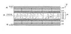
- FIG. 3is an expanded sectional view of a flow plate assembly illustrating a fuel channel and an oxygen-receiving vacuum or sweep gas channel;
- FIG. 4is an expanded sectional view of a flow plate assembly illustrating a fuel channel and streamlines generated by flow impingement elements of the present invention
- FIG. 6Bis an expanded sectional view of a fuel channel and another type of flow impingement elements therein;
- FIG. 6Cis an expanded sectional view of a fuel channel and another type of flow impingement elements therein.
- FIG. 7is an expanded sectional view of a fuel channel having the flow impingement elements displaced from an oxygen permeable membrane by a gap.
- ECD 12is a gas turbine engine, and particularly such engines in aircraft.
- the fuelalso serves as a coolant for one or more sub-systems in the aircraft and becomes heated as it is delivered to fuel injectors immediately prior to combustion.
- the deoxygenated fuel Fdflows from a fuel outlet 30 of the deoxygenation system 14 via a deoxygenated fuel conduit 32 , to the heat exchange system 18 and to the ECD 12 such as the fuel injectors of a gas turbine engine.
- a portion of the deoxygenated fuelmay be recirculated, as represented by recirculation conduit 33 to either the deoxygenation system 14 and/or the reservoir 16 .
- the oxygen permeable membrane 36allows dissolved oxygen (and other gases) to diffuse through angstrom-size voids but excludes the larger fuel molecules. Alternatively, or in conjunction with the voids, the permeable membrane 36 utilizes a solution-diffusion mechanism to dissolve and diffuse oxygen (and/or other gases) through the membrane while excluding the fuel.
- Teflon AFwhich is an amorphous copolymer of perfluoro-2,2-dimethyl-1,3-dioxole (PDD) often identified under the trademark “Teflon AF” registered to E. I.
- Fuel flowing through the fuel channel 38is in contact with the oxygen permeable membrane 36 .
- Vacuumcreates an oxygen partial pressure differential between the inner walls of the fuel channel 38 and the oxygen permeable membrane 36 which causes diffusion of oxygen dissolved within the fuel to migrate through the porous support 42 which supports the membrane 36 and out of the deoxygenator system 14 through the oxygen receiving channel 40 separate from the fuel channel 38 .
- U.S. Pat. No. 6,315,815 entitled MEMBRANE BASED FUEL DEOXYGENATORand U.S. Pat. No. 6,709,492 entitled PLANAR MEMBRANE DEOXYGENATOR which are assigned to the assignee of the instant invention and which are hereby incorporated herein in their entirety.
- one set of plateswhich forms one flow-channel assembly 34 of the deoxygenator system 14 , includes a flow plate assembly 44 sandwiched adjacent to the oxygen permeable membranes 36 which are supported by a porous support 42 such as non-woven polyester sheet (also illustrated in FIG. 3 ). It should be understood that the porous substrate, although schematically illustrated, may take various forms. Adjacent one or more assembly 34 is a separator plate 48 . The separator plate 48 prevents fuel from leaking across the predefined fuel passages defined by the flow plate assemblies 34 .
- the outer housing plates 50 a , 50 bare preferably attached together through a multitude of fasteners such as bolts or the like such that the flow-channel assemblies 34 are sandwiched therebetween.
- the outer housing plates 50 a , 50 bare preferably relatively rigid components which compress the flow-channel assemblies 34 such that sealing between plates is maintained thereby.
- Each flow plate assembly 44defines a portion of the fuel channel 38 between the inlet 26 and outlet 30 .
- the vacuum port 29( FIG. 2A ) is in communication with the interface plate 46 and the porous support 42 through vacuum ports 29 in the flow plates 52 , 54 . Vacuum creates a partial pressure gradient within each of the porous supports 42 to extract dissolved oxygen from the fuel channel 38 through the oxygen permeable membrane 36 . The oxygen is then expelled through the vacuum port 29 .
- Each flow plate assembly 44defines one fuel channel 38 ( FIG. 3 ) between the inlet 26 and outlet 30 ( FIG. 2A ).
- a multitude of parallel flow channels 38are defined between the inlet 26 and outlet 30 by a multitude of the flow-channel assemblies 34 within the deoxygenator system 14 .
- the configuration of each fuel channel 38is preferably defined to maximize fuel exposure to the oxygen permeable membrane 36 in order to maximize the amount of dissolved oxygen removed from the fuel.
- the fuel channels 38are preferably small enough that fuel is in contact with the oxygen permeable membrane 36 but also large enough so as to not restrict fuel flow.
- Each flow plate assembly 44includes a first flow plate 52 , a second flow plate 54 , and a flow plate gasket or seal 56 therebetween. It should be understood that the flow plate assembly 44 disclosed in the illustrative embodiment illustrates only two flow plates and a gasket for the sake of clarity, it should be understood that any number of plate assemblies may be located between the outer housing plates 50 a , 50 b.
- the first flow plate 52 and the second flow plate 54are preferably manufactured of a non-metallic material such as a thermoplastic, for instance polyphenylene sulfide (PPS). It should be understood that other plastics that are compatible with fuel and are electrically conductive (to prevent static charge buildup) may alternatively be utilized as well as materials which are machined rather than molded.
- a non-metallic materialsuch as a thermoplastic, for instance polyphenylene sulfide (PPS).
- PPSpolyphenylene sulfide
- the flow impingement elements 55enhance transport of oxygen from the bulk flow to the membrane surface, while the non-metallic material minimizes weight and sharp edges which may otherwise damage the oxygen permeable membranes 36 .
- the flow impingement elements 55 of the deoxygenator system 14enhance contact between fuel flow and the composite oxygen permeable membrane 36 to increase mass transport of dissolved oxygen.
- each of the flow impingement elements 55define a base segment 60 adjacent the oxygen permeable membrane 36 and a tip segment 58 opposite thereto.
- the base segment 60preferably defines a base thickness between a base wall surface 58 W perpendicular to the membrane surface and back wall 55 W which is greater than a tip thickness defined by the tip segment 58 between a tip wall surface 60 W perpendicular to the membrane surface and the back wall 55 W such that a leading face—that which faces into the fuel flow—of each flow impingement element 55 defines a step shape. That is, the downstream side of the flow impingement elements 55 is relatively straight such that the flow is turned abruptly in the direction normal to the membrane surface.
- the upstream side of the flow impingement elements 55 between the base segment 60 and the tip segment 58is radiused to facilitate manufacturing by injection molding ( FIG. 4 ).
- the base thicknessis preferably approximately 0.027 inches and the tip thickness is preferably approximately 0.015 inches for a fuel channel height of approximately 0.068 inches ( FIG. 5B ).
- each flow impingement element 55is separated from the next flow impingement element 55 by a spacing of approximately 0.125 inches.
- the flow impingement elements 55alternate such that the flow impingement elements 55 from the first flow plate 52 are interleaved with the flow impingement elements 55 from the second adjacent flow plate 54 ( FIG. 5B ).
- the flow impingement elements 55are preferably located directly adjacent the oxygen permeable membrane 36 . That is, no gap exists between the base segment 60 and the membrane 36 . Various gap spacing and fuel streamlines therefore are illustrated in FIG. 7 . In general, as the gap size increases, the flow recirculation zones that existed in the case with no gaps diminish in size or are eliminated. The flow proceeds in essentially an uninterrupted fashion along the oxygen permeable membrane 36 for the cases with relatively large gaps. A periodic interruption of the boundary layers adjacent the oxygen permeable membrane 36 is important in order to increase mass transfer rates; relatively close spacing contact between the flow impingement elements 55 and oxygen permeable membrane 36 is preferred. Applicant has determined, however, that a gap smaller than 0.003 inches is acceptable. Furthermore, the base segment 60 preferably includes a radius to minimize the potential for damage to the relatively delicate oxygen permeable membrane 36 when assembled into the flow plate assembly 44 .
Landscapes
- Chemical & Material Sciences (AREA)
- Chemical Kinetics & Catalysis (AREA)
- Engineering & Computer Science (AREA)
- Water Supply & Treatment (AREA)
- Separation Using Semi-Permeable Membranes (AREA)
- Degasification And Air Bubble Elimination (AREA)
- Production Of Liquid Hydrocarbon Mixture For Refining Petroleum (AREA)
Abstract
Description
Claims (14)
Priority Applications (6)
| Application Number | Priority Date | Filing Date | Title |
|---|---|---|---|
| US11/334,126US7824470B2 (en) | 2006-01-18 | 2006-01-18 | Method for enhancing mass transport in fuel deoxygenation systems |
| CA002568552ACA2568552A1 (en) | 2006-01-18 | 2006-11-20 | A method for enhancing mass transport in fuel deoxygenation systems |
| KR1020060124597AKR20070076409A (en) | 2006-01-18 | 2006-12-08 | Method for Exchanging Mass Transfer in a Fuel Deoxygenation System |
| JP2007003152AJP2007190549A (en) | 2006-01-18 | 2007-01-11 | Fuel system, and method for reducing dissolved oxygen in fuel system |
| CNA2007100020560ACN101015752A (en) | 2006-01-18 | 2007-01-18 | A method for exchanging mass transport in fuel deoxygenation systems |
| EP07250192AEP1810737A1 (en) | 2006-01-18 | 2007-01-18 | A method for enhancing mass transport in fuel deoxygenation systems |
Applications Claiming Priority (1)
| Application Number | Priority Date | Filing Date | Title |
|---|---|---|---|
| US11/334,126US7824470B2 (en) | 2006-01-18 | 2006-01-18 | Method for enhancing mass transport in fuel deoxygenation systems |
Publications (2)
| Publication Number | Publication Date |
|---|---|
| US20070163438A1 US20070163438A1 (en) | 2007-07-19 |
| US7824470B2true US7824470B2 (en) | 2010-11-02 |
Family
ID=37942128
Family Applications (1)
| Application Number | Title | Priority Date | Filing Date |
|---|---|---|---|
| US11/334,126Active2027-11-10US7824470B2 (en) | 2006-01-18 | 2006-01-18 | Method for enhancing mass transport in fuel deoxygenation systems |
Country Status (6)
| Country | Link |
|---|---|
| US (1) | US7824470B2 (en) |
| EP (1) | EP1810737A1 (en) |
| JP (1) | JP2007190549A (en) |
| KR (1) | KR20070076409A (en) |
| CN (1) | CN101015752A (en) |
| CA (1) | CA2568552A1 (en) |
Cited By (29)
| Publication number | Priority date | Publication date | Assignee | Title |
|---|---|---|---|---|
| US20090169965A1 (en)* | 2005-11-22 | 2009-07-02 | Nec Corporation | Gas-liquid separating apparatus and liquid supply type fuel cell |
| US8876946B2 (en) | 2012-04-03 | 2014-11-04 | Hamilton Sundstrand Corporation | Combined fuel stabilization unit and heat exchanger |
| US10215097B2 (en) | 2015-12-08 | 2019-02-26 | General Electric Company | Thermal management system |
| WO2020132656A1 (en) | 2018-12-22 | 2020-06-25 | Air Liquide Advanced Technologies U.S. Llc | Composite hollow fiber membranes for jet fuel de-oxygenation |
| US10914274B1 (en) | 2019-09-11 | 2021-02-09 | General Electric Company | Fuel oxygen reduction unit with plasma reactor |
| US11015534B2 (en) | 2018-11-28 | 2021-05-25 | General Electric Company | Thermal management system |
| US11085636B2 (en) | 2018-11-02 | 2021-08-10 | General Electric Company | Fuel oxygen conversion unit |
| US11131256B2 (en) | 2018-11-02 | 2021-09-28 | General Electric Company | Fuel oxygen conversion unit with a fuel/gas separator |
| US11148824B2 (en) | 2018-11-02 | 2021-10-19 | General Electric Company | Fuel delivery system having a fuel oxygen reduction unit |
| US11161622B2 (en) | 2018-11-02 | 2021-11-02 | General Electric Company | Fuel oxygen reduction unit |
| US11186382B2 (en) | 2018-11-02 | 2021-11-30 | General Electric Company | Fuel oxygen conversion unit |
| US11193671B2 (en) | 2018-11-02 | 2021-12-07 | General Electric Company | Fuel oxygen conversion unit with a fuel gas separator |
| US11319085B2 (en) | 2018-11-02 | 2022-05-03 | General Electric Company | Fuel oxygen conversion unit with valve control |
| US11391211B2 (en) | 2018-11-28 | 2022-07-19 | General Electric Company | Waste heat recovery system |
| US11420763B2 (en) | 2018-11-02 | 2022-08-23 | General Electric Company | Fuel delivery system having a fuel oxygen reduction unit |
| US11434824B2 (en) | 2021-02-03 | 2022-09-06 | General Electric Company | Fuel heater and energy conversion system |
| US11447263B2 (en) | 2018-11-02 | 2022-09-20 | General Electric Company | Fuel oxygen reduction unit control system |
| US11542870B1 (en) | 2021-11-24 | 2023-01-03 | General Electric Company | Gas supply system |
| US11577852B2 (en) | 2018-11-02 | 2023-02-14 | General Electric Company | Fuel oxygen conversion unit |
| US11591965B2 (en) | 2021-03-29 | 2023-02-28 | General Electric Company | Thermal management system for transferring heat between fluids |
| US11773776B2 (en) | 2020-05-01 | 2023-10-03 | General Electric Company | Fuel oxygen reduction unit for prescribed operating conditions |
| US11774427B2 (en) | 2019-11-27 | 2023-10-03 | General Electric Company | Methods and apparatus for monitoring health of fuel oxygen conversion unit |
| US11851204B2 (en) | 2018-11-02 | 2023-12-26 | General Electric Company | Fuel oxygen conversion unit with a dual separator pump |
| US11866182B2 (en) | 2020-05-01 | 2024-01-09 | General Electric Company | Fuel delivery system having a fuel oxygen reduction unit |
| US11906163B2 (en) | 2020-05-01 | 2024-02-20 | General Electric Company | Fuel oxygen conversion unit with integrated water removal |
| US12005377B2 (en) | 2021-06-15 | 2024-06-11 | General Electric Company | Fuel oxygen reduction unit with level control device |
| US12115470B2 (en) | 2021-04-27 | 2024-10-15 | General Electric Company | Fuel oxygen reduction unit |
| US12139270B2 (en) | 2021-04-19 | 2024-11-12 | General Electric Company | Aircraft thermal transport system and method |
| US12226715B2 (en) | 2019-03-26 | 2025-02-18 | Versum Materials Us, Llc | Degassers, degassing systems and the methods of using them |
Families Citing this family (6)
| Publication number | Priority date | Publication date | Assignee | Title |
|---|---|---|---|---|
| DE102010039959A1 (en)* | 2010-08-30 | 2012-03-01 | Aloys Wobben | Fluid degassing apparatus and process for degassing fluids |
| US9687773B2 (en) | 2014-04-30 | 2017-06-27 | Honeywell International Inc. | Fuel deoxygenation and fuel tank inerting system and method |
| US10058818B2 (en)* | 2014-05-27 | 2018-08-28 | University Of Louisville Research Foundation, Inc. | Pre-treatment of samples by electrochemical removal of dissolved gases |
| US9656187B2 (en)* | 2014-11-12 | 2017-05-23 | Honeywell International Inc. | Fuel deoxygenation system contactor-separator |
| MY192191A (en)* | 2016-07-11 | 2022-08-05 | Terra Primoris Holdings Llc | Method for aeration of a flammable liquid to extract flammable vapor |
| US10527011B2 (en)* | 2017-06-06 | 2020-01-07 | Hamilton Sundstrand Corporation | Sonication-assisted fuel deoxygenation |
Citations (99)
| Publication number | Priority date | Publication date | Assignee | Title |
|---|---|---|---|---|
| US4341538A (en)* | 1978-08-18 | 1982-07-27 | Gelman Instrument Company | Intravenous filter |
| US4371385A (en) | 1981-04-28 | 1983-02-01 | Cobe Laboratories, Inc. | Deaerating liquid |
| US4516984A (en) | 1983-11-08 | 1985-05-14 | Emory University | Degassing process and apparatus for removal of oxygen |
| US4525182A (en)* | 1983-08-29 | 1985-06-25 | Millipore Corporation | I.V. Filter apparatus |
| US4602923A (en) | 1984-04-03 | 1986-07-29 | Erwin J. Baumgartler | Apparatus for degasifying a liquid medium |
| US4729773A (en) | 1986-03-04 | 1988-03-08 | Erma Inc. | Unit for degassing liquids |
| JPS63151307A (en) | 1986-12-15 | 1988-06-23 | Toshiba Corp | Degassing treatment apparatus |
| EP0273267A2 (en) | 1986-12-25 | 1988-07-06 | Lignyte Co., Ltd. | Method of separating a particular component from its liquid solution |
| EP0354797A2 (en) | 1988-08-12 | 1990-02-14 | Japan Gore-Tex, Inc. | Degassing device |
| US4955992A (en) | 1987-06-26 | 1990-09-11 | Beckman Instruments, Inc. | Liquid degassing system |
| JPH03169304A (en) | 1989-11-28 | 1991-07-23 | Nitto Denko Corp | Spiral type degassing membrane module |
| JPH03193106A (en) | 1989-12-25 | 1991-08-22 | Fuji Photo Film Co Ltd | Method and apparatus for degassing and defoaming liquid |
| US5053060A (en) | 1990-06-29 | 1991-10-01 | Molecular Devices Corporation | Device and method for degassing, gassing and debubbling liquids |
| EP0460512A1 (en) | 1990-06-05 | 1991-12-11 | Mobil Oil Corporation | Membrane formed of crystalline molecular sieve material |
| US5078755A (en) | 1988-08-20 | 1992-01-07 | Nitto Denko Corporation | Method of removing dissolved gas from liquid |
| US5123937A (en) | 1989-02-03 | 1992-06-23 | Japan Gore-Tex Inc. | Deaerating film and deaerating method |
| EP0493869A1 (en) | 1991-01-04 | 1992-07-08 | Japan Gore-Tex, Inc. | Apparatus for treating water |
| US5154832A (en) | 1990-02-27 | 1992-10-13 | Toray Industries, Inc. | Spiral wound gas permeable membrane module and apparatus and method for using the same |
| JPH0584474A (en) | 1991-09-26 | 1993-04-06 | Hitachi Plant Eng & Constr Co Ltd | Method and apparatus for removing dissolved oxygen |
| EP0552090A1 (en) | 1992-01-17 | 1993-07-21 | Wesley H. Verkaart | Orientation-independent device and method for removal of gas for a cellular fluid |
| JPH05317605A (en) | 1992-05-26 | 1993-12-03 | Dainippon Ink & Chem Inc | Membrane vacuum degassing method and membrane vacuum degassing apparatus |
| EP0576677A1 (en) | 1991-10-23 | 1994-01-05 | TAKANO, Hisateru | Apparatus for exchanging substances |
| EP0583748A1 (en) | 1992-08-14 | 1994-02-23 | Air Products And Chemicals, Inc. | Method for recovering oxygen from oxygen-containing gaseous mixtures |
| WO1994016800A1 (en) | 1993-01-28 | 1994-08-04 | Tygola Pty. Ltd. | Perstraction with chemical reaction |
| US5340384A (en) | 1993-03-05 | 1994-08-23 | Systec, Inc. | Vacuum degassing |
| EP0622475A1 (en) | 1993-04-29 | 1994-11-02 | Applied Materials, Inc. | Method and apparatus for degassing semiconductor processing liquids |
| JPH0780205A (en) | 1993-06-30 | 1995-03-28 | Miura Co Ltd | Selective degassing method and device |
| US5410052A (en) | 1987-02-25 | 1995-04-25 | The Regents Of The University Of California | Symmetrical and unsymmetrical polyalkylamine metal complexes for ligand extraction and generation |
| JPH07227504A (en) | 1994-02-17 | 1995-08-29 | Nomura Micro Sci Co Ltd | Removing method of dissolved oxygen |
| US5482860A (en) | 1989-03-07 | 1996-01-09 | Oxyrase, Inc. | Apparatus for continuously removing oxygen from fluid streams |
| JPH08906A (en) | 1992-05-06 | 1996-01-09 | Mikuni Kikai Kk | Degassing device |
| US5522917A (en) | 1993-08-31 | 1996-06-04 | Miura Co., Ltd. | Method for deaerating liquid products |
| JPH08332306A (en) | 1995-06-06 | 1996-12-17 | Japan Gore Tex Inc | Degassing membrane and degassing module |
| EP0750322A1 (en) | 1995-06-19 | 1996-12-27 | Jürgen Bastian | Minimization of gas content in liquids used for heat exchange and insulating purposes |
| WO1997002190A1 (en) | 1995-07-05 | 1997-01-23 | Astra Plastique | Venting closure and its manufacture |
| US5693122A (en) | 1994-12-23 | 1997-12-02 | Hewlett Packard Company | Basic structure for a liquid chromatography degasser |
| US5695545A (en) | 1996-05-10 | 1997-12-09 | Hoechst Celanese Corporation | Degassing liquids: apparatus and method |
| JPH10174803A (en) | 1996-12-17 | 1998-06-30 | Hitachi Building Syst Co Ltd | Gas removal device in oil |
| JPH10216404A (en) | 1997-02-07 | 1998-08-18 | Tokyo Electron Ltd | Deaeration mechanism and treating device using the same |
| US5827429A (en)* | 1996-01-18 | 1998-10-27 | Filtertek Inc. | Intravenous filter device |
| JPH119902A (en) | 1997-06-26 | 1999-01-19 | Dainippon Ink & Chem Inc | Liquid degassing module |
| JPH1133373A (en) | 1998-04-10 | 1999-02-09 | Mitsubishi Rayon Co Ltd | Composite hollow fiber membrane |
| US5888275A (en) | 1996-02-26 | 1999-03-30 | Japan Gore-Tex, Inc. | Assembly for deaeration of liquids |
| US5902747A (en) | 1996-10-24 | 1999-05-11 | Compact Membrane Systems, Inc. | Method of gasifying or degasifying a liquid containing cells |
| US5902382A (en) | 1995-02-15 | 1999-05-11 | Solutions Services Systems France S.A. | Degassing system for a hydrocarbon dispenser |
| WO1999039811A1 (en) | 1996-09-19 | 1999-08-12 | Anjou Recherche | Hollow fiber membrane carpet manufacturing method, an elementary hollow fiber membrane carpet member and hollow fiber membrane carpet |
| JPH11244607A (en) | 1998-03-03 | 1999-09-14 | Mitsubishi Rayon Co Ltd | Degassing method and degassing device for chemical solution |
| EP0963229A1 (en) | 1997-02-06 | 1999-12-15 | Jens Pannenborg | Process for degassing liquids |
| EP0970738A1 (en) | 1996-12-24 | 2000-01-12 | Kitz Corporation | Hollow-fiber membrane module and process for the production thereof |
| JP2000051606A (en) | 1998-08-07 | 2000-02-22 | Japan Organo Co Ltd | Gas permeation membrane apparatus |
| JP2000084368A (en) | 1998-09-08 | 2000-03-28 | Mitsubishi Rayon Co Ltd | Composite hollow fiber membrane for chemical solution deaeration |
| JP2000140505A (en) | 1998-11-12 | 2000-05-23 | Tokyo Electron Ltd | Apparatus and method for degassing |
| EP1018353A1 (en) | 1999-01-05 | 2000-07-12 | Erc Inc. | Vacuum deaeration device |
| WO2000044479A1 (en) | 1999-01-29 | 2000-08-03 | Millipore Corporation | Hollow fiber membrane contactor |
| WO2000044482A2 (en) | 1999-01-29 | 2000-08-03 | Millipore Corporation | Skinned hollow fiber membrane and method of manufacture |
| US6106591A (en) | 1997-06-23 | 2000-08-22 | Praxair Technology, Inc. | Process for reducing carbon production in solid electrolyte ionic conductor systems |
| JP2000262871A (en) | 1999-01-11 | 2000-09-26 | Kawamura Inst Of Chem Res | Microporous membrane separation device and its production |
| JP2000288366A (en) | 1999-04-02 | 2000-10-17 | Mitsubishi Rayon Co Ltd | Composite flat membrane |
| EP1052011A1 (en) | 1997-04-30 | 2000-11-15 | Mitsubishi Rayon Co., Ltd. | Ink deaerating hollow yarn membrane, ink deaerating method, ink deaerating apparatus, ink cartridge manufacturing method, and ink |
| JP2000350902A (en) | 1999-06-09 | 2000-12-19 | Fuji Photo Film Co Ltd | Deaeration method |
| US6168648B1 (en) | 1997-12-25 | 2001-01-02 | Nitto Denko Corporation | Spiral wound type membrane module, spiral wound type membrane element and running method thereof |
| JP3169304B2 (en) | 1994-06-20 | 2001-05-21 | ユニ・チャーム株式会社 | Sanitary napkins in individual bags |
| US6258154B1 (en) | 1998-07-17 | 2001-07-10 | Hewlett-Packard Company | Apparatus for degassing liquids |
| JP3193106B2 (en) | 1992-03-05 | 2001-07-30 | 日東電工株式会社 | Method for curing epoxy resin composition and cured product |
| US6309444B1 (en) | 1999-08-20 | 2001-10-30 | Systec Inc. | Post-blending valve degasser |
| US20010035093A1 (en) | 2000-03-03 | 2001-11-01 | Takushi Yokota | Gas permeable membrane apparatus |
| US6315815B1 (en) | 1999-12-16 | 2001-11-13 | United Technologies Corporation | Membrane based fuel deoxygenator |
| US6379796B1 (en) | 1997-10-02 | 2002-04-30 | Mitsubishi Rayon Co., Ltd. | Composite hollow fiber membrane |
| EP1210971A1 (en) | 2000-11-21 | 2002-06-05 | Praxair Technology, Inc. | Process for making microporous membranes having selected gas-selective sites and the membranes so made |
| US6402810B1 (en) | 1997-04-23 | 2002-06-11 | Daimlerchrysler Ag | Method for dehydrating and/or degassing hydraulic fluids, device for carrying out said method and use of said device |
| US6402818B1 (en) | 2000-06-02 | 2002-06-11 | Celgard Inc. | Degassing a liquid with a membrane contactor |
| EP1239189A2 (en) | 2001-03-09 | 2002-09-11 | MAN Nutzfahrzeuge Aktiengesellschaft | Spray water protected venting device for gear boxes, especially for motor vehicles |
| US20020195385A1 (en) | 2001-06-21 | 2002-12-26 | Kwantai Cho | Hollow fiber membrane contactor |
| JP2003010604A (en) | 2001-07-02 | 2003-01-14 | Mitsubishi Rayon Co Ltd | Degassing device |
| EP1277504A2 (en) | 2001-07-16 | 2003-01-22 | Systec Inc. | Film degassing system |
| US6523572B1 (en)* | 1999-08-25 | 2003-02-25 | Core Flow Ltd. | Apparatus for inducing forces by fluid injection |
| JP2003062403A (en) | 2001-08-24 | 2003-03-04 | Ebara Corp | Operating method for membrane degasifier |
| WO2003029744A2 (en) | 2001-10-01 | 2003-04-10 | Mykrolis Corporation | A thermoplastic heat exchanger and method of making the same |
| WO2003036747A1 (en) | 2001-10-22 | 2003-05-01 | Protonex Technology Corporation | One-shot fabrication of membrane-based electrochemical cell stacks |
| US20030116015A1 (en) | 2001-03-22 | 2003-06-26 | Amitava Sengupta | Contactor for debubbling an ink |
| JP2003200024A (en) | 2001-10-31 | 2003-07-15 | Sekisui Chem Co Ltd | module |
| US20030148164A1 (en) | 2001-09-07 | 2003-08-07 | Koch Carol A. | Efficient fuel cell water transport plates |
| US20030151156A1 (en) | 2002-02-12 | 2003-08-14 | Crumm Aaron T. | Solid state electrochemical devices |
| US20030161785A1 (en) | 2002-02-22 | 2003-08-28 | Dieckmann Gunther H. | Process for reducing metal catalyzed coke formation in hydrocarbon processing |
| JP2003245525A (en) | 2002-02-25 | 2003-09-02 | Sekisui Chem Co Ltd | Module |
| WO2003080228A1 (en) | 2002-03-19 | 2003-10-02 | Mykrolis Corporation | Hollow fiber membrane contact apparatus and process |
| WO2003086573A1 (en) | 2002-04-08 | 2003-10-23 | Dominion Engineering, Inc. | Liquid degassing system for power plant system layup |
| US20030219637A1 (en) | 2002-05-22 | 2003-11-27 | Coors W. Grover | Direct hydrocarbon reforming in protonic ceramic fuel cells by electrolyte steam permeation |
| WO2004007060A2 (en) | 2002-07-11 | 2004-01-22 | Pall Corporation | Uv treated membranes |
| US6682016B1 (en) | 2002-09-05 | 2004-01-27 | Hamilton Sundstrand | Thermal management valve with drop-tight shutoff of return to tank |
| US20040028988A1 (en) | 2002-08-06 | 2004-02-12 | General Electric Company | Fiber cooling of fuel cells |
| US20040050786A1 (en) | 2002-09-12 | 2004-03-18 | Avijit Dey | Method of removing organic impurities from water |
| US6709492B1 (en)* | 2003-04-04 | 2004-03-23 | United Technologies Corporation | Planar membrane deoxygenator |
| US20040094463A1 (en) | 2000-09-13 | 2004-05-20 | Marc Laverdiere | Liquid filtration device |
| WO2004041397A2 (en) | 2002-05-09 | 2004-05-21 | Massachusetts Institute Of Technology | Preparation of asymmetric membranes using hot-filament chemical vapor deposition |
| US20040194627A1 (en)* | 2003-04-04 | 2004-10-07 | United Technologies Corporation | System and method for thermal management |
| US6811592B2 (en)* | 2002-03-01 | 2004-11-02 | Johnson & Johnson Vision Care, Inc. | Thin film in-line degasser |
| US7140495B2 (en)* | 2001-12-14 | 2006-11-28 | 3M Innovative Properties Company | Layered sheet construction for wastewater treatment |
| US7393388B2 (en)* | 2005-05-13 | 2008-07-01 | United Technologies Corporation | Spiral wound fuel stabilization unit for fuel de-oxygenation |
Family Cites Families (2)
| Publication number | Priority date | Publication date | Assignee | Title |
|---|---|---|---|---|
| US5178755A (en)* | 1992-02-20 | 1993-01-12 | Estr Inc. | UV-enhanced ozone wastewater treatment system |
| WO2006104241A1 (en)* | 2005-03-29 | 2006-10-05 | Fujifilm Corporation | Reaction method and apparatus and method and apparatus for manufacturing chemical substance using the same |
- 2006
- 2006-01-18USUS11/334,126patent/US7824470B2/enactiveActive
- 2006-11-20CACA002568552Apatent/CA2568552A1/ennot_activeAbandoned
- 2006-12-08KRKR1020060124597Apatent/KR20070076409A/ennot_activeAbandoned
- 2007
- 2007-01-11JPJP2007003152Apatent/JP2007190549A/enactivePending
- 2007-01-18EPEP07250192Apatent/EP1810737A1/ennot_activeWithdrawn
- 2007-01-18CNCNA2007100020560Apatent/CN101015752A/enactivePending
Patent Citations (105)
| Publication number | Priority date | Publication date | Assignee | Title |
|---|---|---|---|---|
| US4341538A (en)* | 1978-08-18 | 1982-07-27 | Gelman Instrument Company | Intravenous filter |
| US4371385A (en) | 1981-04-28 | 1983-02-01 | Cobe Laboratories, Inc. | Deaerating liquid |
| US4525182A (en)* | 1983-08-29 | 1985-06-25 | Millipore Corporation | I.V. Filter apparatus |
| US4516984A (en) | 1983-11-08 | 1985-05-14 | Emory University | Degassing process and apparatus for removal of oxygen |
| US4602923A (en) | 1984-04-03 | 1986-07-29 | Erwin J. Baumgartler | Apparatus for degasifying a liquid medium |
| US4729773A (en) | 1986-03-04 | 1988-03-08 | Erma Inc. | Unit for degassing liquids |
| JPS63151307A (en) | 1986-12-15 | 1988-06-23 | Toshiba Corp | Degassing treatment apparatus |
| EP0273267A2 (en) | 1986-12-25 | 1988-07-06 | Lignyte Co., Ltd. | Method of separating a particular component from its liquid solution |
| US5410052A (en) | 1987-02-25 | 1995-04-25 | The Regents Of The University Of California | Symmetrical and unsymmetrical polyalkylamine metal complexes for ligand extraction and generation |
| US4955992A (en) | 1987-06-26 | 1990-09-11 | Beckman Instruments, Inc. | Liquid degassing system |
| EP0354797A2 (en) | 1988-08-12 | 1990-02-14 | Japan Gore-Tex, Inc. | Degassing device |
| US5078755A (en) | 1988-08-20 | 1992-01-07 | Nitto Denko Corporation | Method of removing dissolved gas from liquid |
| US5123937A (en) | 1989-02-03 | 1992-06-23 | Japan Gore-Tex Inc. | Deaerating film and deaerating method |
| US5482860A (en) | 1989-03-07 | 1996-01-09 | Oxyrase, Inc. | Apparatus for continuously removing oxygen from fluid streams |
| JPH03169304A (en) | 1989-11-28 | 1991-07-23 | Nitto Denko Corp | Spiral type degassing membrane module |
| JPH03193106A (en) | 1989-12-25 | 1991-08-22 | Fuji Photo Film Co Ltd | Method and apparatus for degassing and defoaming liquid |
| US5154832A (en) | 1990-02-27 | 1992-10-13 | Toray Industries, Inc. | Spiral wound gas permeable membrane module and apparatus and method for using the same |
| EP0460512A1 (en) | 1990-06-05 | 1991-12-11 | Mobil Oil Corporation | Membrane formed of crystalline molecular sieve material |
| US5053060A (en) | 1990-06-29 | 1991-10-01 | Molecular Devices Corporation | Device and method for degassing, gassing and debubbling liquids |
| EP0493869A1 (en) | 1991-01-04 | 1992-07-08 | Japan Gore-Tex, Inc. | Apparatus for treating water |
| JPH0584474A (en) | 1991-09-26 | 1993-04-06 | Hitachi Plant Eng & Constr Co Ltd | Method and apparatus for removing dissolved oxygen |
| EP0576677A1 (en) | 1991-10-23 | 1994-01-05 | TAKANO, Hisateru | Apparatus for exchanging substances |
| EP0552090A1 (en) | 1992-01-17 | 1993-07-21 | Wesley H. Verkaart | Orientation-independent device and method for removal of gas for a cellular fluid |
| JP3193106B2 (en) | 1992-03-05 | 2001-07-30 | 日東電工株式会社 | Method for curing epoxy resin composition and cured product |
| JPH08906A (en) | 1992-05-06 | 1996-01-09 | Mikuni Kikai Kk | Degassing device |
| JPH05317605A (en) | 1992-05-26 | 1993-12-03 | Dainippon Ink & Chem Inc | Membrane vacuum degassing method and membrane vacuum degassing apparatus |
| EP0583748A1 (en) | 1992-08-14 | 1994-02-23 | Air Products And Chemicals, Inc. | Method for recovering oxygen from oxygen-containing gaseous mixtures |
| WO1994016800A1 (en) | 1993-01-28 | 1994-08-04 | Tygola Pty. Ltd. | Perstraction with chemical reaction |
| US5340384A (en) | 1993-03-05 | 1994-08-23 | Systec, Inc. | Vacuum degassing |
| EP0622475A1 (en) | 1993-04-29 | 1994-11-02 | Applied Materials, Inc. | Method and apparatus for degassing semiconductor processing liquids |
| JPH0780205A (en) | 1993-06-30 | 1995-03-28 | Miura Co Ltd | Selective degassing method and device |
| US5522917A (en) | 1993-08-31 | 1996-06-04 | Miura Co., Ltd. | Method for deaerating liquid products |
| JPH07227504A (en) | 1994-02-17 | 1995-08-29 | Nomura Micro Sci Co Ltd | Removing method of dissolved oxygen |
| JP3169304B2 (en) | 1994-06-20 | 2001-05-21 | ユニ・チャーム株式会社 | Sanitary napkins in individual bags |
| US5693122A (en) | 1994-12-23 | 1997-12-02 | Hewlett Packard Company | Basic structure for a liquid chromatography degasser |
| US5902382A (en) | 1995-02-15 | 1999-05-11 | Solutions Services Systems France S.A. | Degassing system for a hydrocarbon dispenser |
| JPH08332306A (en) | 1995-06-06 | 1996-12-17 | Japan Gore Tex Inc | Degassing membrane and degassing module |
| EP0750322A1 (en) | 1995-06-19 | 1996-12-27 | Jürgen Bastian | Minimization of gas content in liquids used for heat exchange and insulating purposes |
| WO1997002190A1 (en) | 1995-07-05 | 1997-01-23 | Astra Plastique | Venting closure and its manufacture |
| US5827429A (en)* | 1996-01-18 | 1998-10-27 | Filtertek Inc. | Intravenous filter device |
| US5888275A (en) | 1996-02-26 | 1999-03-30 | Japan Gore-Tex, Inc. | Assembly for deaeration of liquids |
| US5695545A (en) | 1996-05-10 | 1997-12-09 | Hoechst Celanese Corporation | Degassing liquids: apparatus and method |
| WO1999039811A1 (en) | 1996-09-19 | 1999-08-12 | Anjou Recherche | Hollow fiber membrane carpet manufacturing method, an elementary hollow fiber membrane carpet member and hollow fiber membrane carpet |
| US5902747A (en) | 1996-10-24 | 1999-05-11 | Compact Membrane Systems, Inc. | Method of gasifying or degasifying a liquid containing cells |
| JPH10174803A (en) | 1996-12-17 | 1998-06-30 | Hitachi Building Syst Co Ltd | Gas removal device in oil |
| US6623637B1 (en) | 1996-12-24 | 2003-09-23 | Kitz Corporation | Hollow-fiber membrane module |
| EP0970738A1 (en) | 1996-12-24 | 2000-01-12 | Kitz Corporation | Hollow-fiber membrane module and process for the production thereof |
| EP0963229A1 (en) | 1997-02-06 | 1999-12-15 | Jens Pannenborg | Process for degassing liquids |
| JPH10216404A (en) | 1997-02-07 | 1998-08-18 | Tokyo Electron Ltd | Deaeration mechanism and treating device using the same |
| US6402810B1 (en) | 1997-04-23 | 2002-06-11 | Daimlerchrysler Ag | Method for dehydrating and/or degassing hydraulic fluids, device for carrying out said method and use of said device |
| EP1052011A1 (en) | 1997-04-30 | 2000-11-15 | Mitsubishi Rayon Co., Ltd. | Ink deaerating hollow yarn membrane, ink deaerating method, ink deaerating apparatus, ink cartridge manufacturing method, and ink |
| US6106591A (en) | 1997-06-23 | 2000-08-22 | Praxair Technology, Inc. | Process for reducing carbon production in solid electrolyte ionic conductor systems |
| JPH119902A (en) | 1997-06-26 | 1999-01-19 | Dainippon Ink & Chem Inc | Liquid degassing module |
| US6379796B1 (en) | 1997-10-02 | 2002-04-30 | Mitsubishi Rayon Co., Ltd. | Composite hollow fiber membrane |
| US6168648B1 (en) | 1997-12-25 | 2001-01-02 | Nitto Denko Corporation | Spiral wound type membrane module, spiral wound type membrane element and running method thereof |
| JPH11244607A (en) | 1998-03-03 | 1999-09-14 | Mitsubishi Rayon Co Ltd | Degassing method and degassing device for chemical solution |
| JPH1133373A (en) | 1998-04-10 | 1999-02-09 | Mitsubishi Rayon Co Ltd | Composite hollow fiber membrane |
| US6258154B1 (en) | 1998-07-17 | 2001-07-10 | Hewlett-Packard Company | Apparatus for degassing liquids |
| JP2000051606A (en) | 1998-08-07 | 2000-02-22 | Japan Organo Co Ltd | Gas permeation membrane apparatus |
| JP2000084368A (en) | 1998-09-08 | 2000-03-28 | Mitsubishi Rayon Co Ltd | Composite hollow fiber membrane for chemical solution deaeration |
| JP2000140505A (en) | 1998-11-12 | 2000-05-23 | Tokyo Electron Ltd | Apparatus and method for degassing |
| EP1018353A1 (en) | 1999-01-05 | 2000-07-12 | Erc Inc. | Vacuum deaeration device |
| JP2000262871A (en) | 1999-01-11 | 2000-09-26 | Kawamura Inst Of Chem Res | Microporous membrane separation device and its production |
| WO2000044482A2 (en) | 1999-01-29 | 2000-08-03 | Millipore Corporation | Skinned hollow fiber membrane and method of manufacture |
| WO2000044479A1 (en) | 1999-01-29 | 2000-08-03 | Millipore Corporation | Hollow fiber membrane contactor |
| JP2000288366A (en) | 1999-04-02 | 2000-10-17 | Mitsubishi Rayon Co Ltd | Composite flat membrane |
| JP2000350902A (en) | 1999-06-09 | 2000-12-19 | Fuji Photo Film Co Ltd | Deaeration method |
| US6309444B1 (en) | 1999-08-20 | 2001-10-30 | Systec Inc. | Post-blending valve degasser |
| US6494938B2 (en) | 1999-08-20 | 2002-12-17 | Systec, Inc. | Vacuum degassing |
| US6523572B1 (en)* | 1999-08-25 | 2003-02-25 | Core Flow Ltd. | Apparatus for inducing forces by fluid injection |
| US6315815B1 (en) | 1999-12-16 | 2001-11-13 | United Technologies Corporation | Membrane based fuel deoxygenator |
| US20010035093A1 (en) | 2000-03-03 | 2001-11-01 | Takushi Yokota | Gas permeable membrane apparatus |
| US6402818B1 (en) | 2000-06-02 | 2002-06-11 | Celgard Inc. | Degassing a liquid with a membrane contactor |
| US20040094463A1 (en) | 2000-09-13 | 2004-05-20 | Marc Laverdiere | Liquid filtration device |
| EP1210971A1 (en) | 2000-11-21 | 2002-06-05 | Praxair Technology, Inc. | Process for making microporous membranes having selected gas-selective sites and the membranes so made |
| EP1239189A2 (en) | 2001-03-09 | 2002-09-11 | MAN Nutzfahrzeuge Aktiengesellschaft | Spray water protected venting device for gear boxes, especially for motor vehicles |
| US20030116015A1 (en) | 2001-03-22 | 2003-06-26 | Amitava Sengupta | Contactor for debubbling an ink |
| EP1270063A2 (en) | 2001-06-21 | 2003-01-02 | Celgard Inc. | Hollow fiber membrane contactor |
| US6616841B2 (en) | 2001-06-21 | 2003-09-09 | Celgard Inc. | Hollow fiber membrane contactor |
| US20020195385A1 (en) | 2001-06-21 | 2002-12-26 | Kwantai Cho | Hollow fiber membrane contactor |
| JP2003010604A (en) | 2001-07-02 | 2003-01-14 | Mitsubishi Rayon Co Ltd | Degassing device |
| EP1277504A2 (en) | 2001-07-16 | 2003-01-22 | Systec Inc. | Film degassing system |
| JP2003062403A (en) | 2001-08-24 | 2003-03-04 | Ebara Corp | Operating method for membrane degasifier |
| US20030148164A1 (en) | 2001-09-07 | 2003-08-07 | Koch Carol A. | Efficient fuel cell water transport plates |
| WO2003029744A2 (en) | 2001-10-01 | 2003-04-10 | Mykrolis Corporation | A thermoplastic heat exchanger and method of making the same |
| WO2003036747A1 (en) | 2001-10-22 | 2003-05-01 | Protonex Technology Corporation | One-shot fabrication of membrane-based electrochemical cell stacks |
| JP2003200024A (en) | 2001-10-31 | 2003-07-15 | Sekisui Chem Co Ltd | module |
| US7140495B2 (en)* | 2001-12-14 | 2006-11-28 | 3M Innovative Properties Company | Layered sheet construction for wastewater treatment |
| US20030151156A1 (en) | 2002-02-12 | 2003-08-14 | Crumm Aaron T. | Solid state electrochemical devices |
| US20030161785A1 (en) | 2002-02-22 | 2003-08-28 | Dieckmann Gunther H. | Process for reducing metal catalyzed coke formation in hydrocarbon processing |
| JP2003245525A (en) | 2002-02-25 | 2003-09-02 | Sekisui Chem Co Ltd | Module |
| US6811592B2 (en)* | 2002-03-01 | 2004-11-02 | Johnson & Johnson Vision Care, Inc. | Thin film in-line degasser |
| WO2003080228A1 (en) | 2002-03-19 | 2003-10-02 | Mykrolis Corporation | Hollow fiber membrane contact apparatus and process |
| US20040025696A1 (en) | 2002-04-08 | 2004-02-12 | Varrin Robert D. | Liquid degassing system for power plant system layup |
| WO2003086573A1 (en) | 2002-04-08 | 2003-10-23 | Dominion Engineering, Inc. | Liquid degassing system for power plant system layup |
| WO2004041397A2 (en) | 2002-05-09 | 2004-05-21 | Massachusetts Institute Of Technology | Preparation of asymmetric membranes using hot-filament chemical vapor deposition |
| US20030219637A1 (en) | 2002-05-22 | 2003-11-27 | Coors W. Grover | Direct hydrocarbon reforming in protonic ceramic fuel cells by electrolyte steam permeation |
| WO2004007060A2 (en) | 2002-07-11 | 2004-01-22 | Pall Corporation | Uv treated membranes |
| US20040028988A1 (en) | 2002-08-06 | 2004-02-12 | General Electric Company | Fiber cooling of fuel cells |
| US6682016B1 (en) | 2002-09-05 | 2004-01-27 | Hamilton Sundstrand | Thermal management valve with drop-tight shutoff of return to tank |
| US20040050786A1 (en) | 2002-09-12 | 2004-03-18 | Avijit Dey | Method of removing organic impurities from water |
| US6709492B1 (en)* | 2003-04-04 | 2004-03-23 | United Technologies Corporation | Planar membrane deoxygenator |
| US20040194627A1 (en)* | 2003-04-04 | 2004-10-07 | United Technologies Corporation | System and method for thermal management |
| WO2005025718A1 (en) | 2003-09-08 | 2005-03-24 | United Technologies Corporation | System and method for thermal management |
| US7393388B2 (en)* | 2005-05-13 | 2008-07-01 | United Technologies Corporation | Spiral wound fuel stabilization unit for fuel de-oxygenation |
Non-Patent Citations (6)
| Title |
|---|
| Richard W. Baker, "Membrane Technology and Applications," 2nd Edition, John Wiley & Sons, Ltd., pp. 96-103. |
| U.S. Appl. No. 11/049,175, entitled "Fuel Deoxygenation System With Textured Oxygen Permeable Membrane," filed Feb. 2, 2005. |
| U.S. Appl. No. 11/148,508, entitled Fuel Deoxygenation System With Non-Planar Plate Members, filed Jun. 9, 2005. |
| U.S. Appl. No. 11/265,845, entitled "Fuel Deoxygenation System With Multi-Layer Oxygen Permeable Membrane", filed Nov. 3, 2005. |
| U.S. Appl. No. 11/334,587, entitled "Fuel Deoxygenator With Non-Planar Fuel Channel and Oxygen Permeable Membrane," filed Jan. 18, 2006. |
| U.S. Appl. No. 11/334,590, entitled "Fuel Deoxygenation System With Non-Metallic Fuel Plate Assembly", filed Jan. 18, 2006. |
Cited By (35)
| Publication number | Priority date | Publication date | Assignee | Title |
|---|---|---|---|---|
| US20090169965A1 (en)* | 2005-11-22 | 2009-07-02 | Nec Corporation | Gas-liquid separating apparatus and liquid supply type fuel cell |
| US8876946B2 (en) | 2012-04-03 | 2014-11-04 | Hamilton Sundstrand Corporation | Combined fuel stabilization unit and heat exchanger |
| US11098647B2 (en) | 2015-12-08 | 2021-08-24 | General Electric Company | Thermal management system |
| US10215097B2 (en) | 2015-12-08 | 2019-02-26 | General Electric Company | Thermal management system |
| US11420763B2 (en) | 2018-11-02 | 2022-08-23 | General Electric Company | Fuel delivery system having a fuel oxygen reduction unit |
| US11319085B2 (en) | 2018-11-02 | 2022-05-03 | General Electric Company | Fuel oxygen conversion unit with valve control |
| US11085636B2 (en) | 2018-11-02 | 2021-08-10 | General Electric Company | Fuel oxygen conversion unit |
| US11851204B2 (en) | 2018-11-02 | 2023-12-26 | General Electric Company | Fuel oxygen conversion unit with a dual separator pump |
| US11131256B2 (en) | 2018-11-02 | 2021-09-28 | General Electric Company | Fuel oxygen conversion unit with a fuel/gas separator |
| US11148824B2 (en) | 2018-11-02 | 2021-10-19 | General Electric Company | Fuel delivery system having a fuel oxygen reduction unit |
| US11161622B2 (en) | 2018-11-02 | 2021-11-02 | General Electric Company | Fuel oxygen reduction unit |
| US11186382B2 (en) | 2018-11-02 | 2021-11-30 | General Electric Company | Fuel oxygen conversion unit |
| US11193671B2 (en) | 2018-11-02 | 2021-12-07 | General Electric Company | Fuel oxygen conversion unit with a fuel gas separator |
| US11577852B2 (en) | 2018-11-02 | 2023-02-14 | General Electric Company | Fuel oxygen conversion unit |
| US11945600B2 (en) | 2018-11-02 | 2024-04-02 | General Electric Company | Fuel delivery system having a fuel oxygen reduction unit |
| US11447263B2 (en) | 2018-11-02 | 2022-09-20 | General Electric Company | Fuel oxygen reduction unit control system |
| US11506131B2 (en) | 2018-11-28 | 2022-11-22 | General Electric Company | Thermal management system |
| US11391211B2 (en) | 2018-11-28 | 2022-07-19 | General Electric Company | Waste heat recovery system |
| US11015534B2 (en) | 2018-11-28 | 2021-05-25 | General Electric Company | Thermal management system |
| WO2020132656A1 (en) | 2018-12-22 | 2020-06-25 | Air Liquide Advanced Technologies U.S. Llc | Composite hollow fiber membranes for jet fuel de-oxygenation |
| US12226715B2 (en) | 2019-03-26 | 2025-02-18 | Versum Materials Us, Llc | Degassers, degassing systems and the methods of using them |
| US10914274B1 (en) | 2019-09-11 | 2021-02-09 | General Electric Company | Fuel oxygen reduction unit with plasma reactor |
| US11774427B2 (en) | 2019-11-27 | 2023-10-03 | General Electric Company | Methods and apparatus for monitoring health of fuel oxygen conversion unit |
| US11773776B2 (en) | 2020-05-01 | 2023-10-03 | General Electric Company | Fuel oxygen reduction unit for prescribed operating conditions |
| US11866182B2 (en) | 2020-05-01 | 2024-01-09 | General Electric Company | Fuel delivery system having a fuel oxygen reduction unit |
| US11906163B2 (en) | 2020-05-01 | 2024-02-20 | General Electric Company | Fuel oxygen conversion unit with integrated water removal |
| US11767793B2 (en) | 2021-02-03 | 2023-09-26 | General Electric Company | Fuel heater and energy conversion system |
| US12173654B2 (en) | 2021-02-03 | 2024-12-24 | General Electric Company | Fuel heater and energy conversion system |
| US11434824B2 (en) | 2021-02-03 | 2022-09-06 | General Electric Company | Fuel heater and energy conversion system |
| US11591965B2 (en) | 2021-03-29 | 2023-02-28 | General Electric Company | Thermal management system for transferring heat between fluids |
| US12139270B2 (en) | 2021-04-19 | 2024-11-12 | General Electric Company | Aircraft thermal transport system and method |
| US12115470B2 (en) | 2021-04-27 | 2024-10-15 | General Electric Company | Fuel oxygen reduction unit |
| US12005377B2 (en) | 2021-06-15 | 2024-06-11 | General Electric Company | Fuel oxygen reduction unit with level control device |
| US11879392B2 (en) | 2021-11-24 | 2024-01-23 | General Electric Company | Gas supply system |
| US11542870B1 (en) | 2021-11-24 | 2023-01-03 | General Electric Company | Gas supply system |
Also Published As
| Publication number | Publication date |
|---|---|
| US20070163438A1 (en) | 2007-07-19 |
| JP2007190549A (en) | 2007-08-02 |
| CN101015752A (en) | 2007-08-15 |
| CA2568552A1 (en) | 2007-07-18 |
| EP1810737A1 (en) | 2007-07-25 |
| KR20070076409A (en) | 2007-07-24 |
Similar Documents
| Publication | Publication Date | Title |
|---|---|---|
| US7824470B2 (en) | Method for enhancing mass transport in fuel deoxygenation systems | |
| US7465336B2 (en) | Fuel deoxygenation system with non-planar plate members | |
| EP1782879B1 (en) | Fuel deoxygenation system with multi-layer oxygen permeable membrane | |
| EP1464376B1 (en) | Planar membrane deoxygenator | |
| US7569099B2 (en) | Fuel deoxygenation system with non-metallic fuel plate assembly | |
| US8177884B2 (en) | Fuel deoxygenator with porous support plate | |
| US7582137B2 (en) | Fuel deoxygenator with non-planar fuel channel and oxygen permeable membrane | |
| EP1559883B1 (en) | Gas turbine engine comprising a fuel deoxygenator | |
| US20050137441A1 (en) | Multi-stage fuel deoxygenator | |
| US8876946B2 (en) | Combined fuel stabilization unit and heat exchanger | |
| EP3434752A1 (en) | Fuel tank de-oxygenation system | |
| EP3434347A1 (en) | Fuel tank de-oxygenation system | |
| CA2545897A1 (en) | Fuel deoxygenation system with non-planar plate members |
Legal Events
| Date | Code | Title | Description |
|---|---|---|---|
| AS | Assignment | Owner name:UNITED TECHNOLOGIES CORPORATION, CONNECTICUT Free format text:ASSIGNMENT OF ASSIGNORS INTEREST;ASSIGNORS:CHIAPETTA, LOUIS;SPADACCINI, LOUIS J.;HUANG, HE;AND OTHERS;REEL/FRAME:017490/0249;SIGNING DATES FROM 20051130 TO 20060103 Owner name:UNITED TECHNOLOGIES CORPORATION, CONNECTICUT Free format text:ASSIGNMENT OF ASSIGNORS INTEREST;ASSIGNORS:CHIAPETTA, LOUIS;SPADACCINI, LOUIS J.;HUANG, HE;AND OTHERS;SIGNING DATES FROM 20051130 TO 20060103;REEL/FRAME:017490/0249 | |
| STCF | Information on status: patent grant | Free format text:PATENTED CASE | |
| FPAY | Fee payment | Year of fee payment:4 | |
| MAFP | Maintenance fee payment | Free format text:PAYMENT OF MAINTENANCE FEE, 8TH YEAR, LARGE ENTITY (ORIGINAL EVENT CODE: M1552) Year of fee payment:8 | |
| AS | Assignment | Owner name:RAYTHEON TECHNOLOGIES CORPORATION, MASSACHUSETTS Free format text:CHANGE OF NAME;ASSIGNOR:UNITED TECHNOLOGIES CORPORATION;REEL/FRAME:054062/0001 Effective date:20200403 | |
| AS | Assignment | Owner name:RAYTHEON TECHNOLOGIES CORPORATION, CONNECTICUT Free format text:CORRECTIVE ASSIGNMENT TO CORRECT THE AND REMOVE PATENT APPLICATION NUMBER 11886281 AND ADD PATENT APPLICATION NUMBER 14846874. TO CORRECT THE RECEIVING PARTY ADDRESS PREVIOUSLY RECORDED AT REEL: 054062 FRAME: 0001. ASSIGNOR(S) HEREBY CONFIRMS THE CHANGE OF ADDRESS;ASSIGNOR:UNITED TECHNOLOGIES CORPORATION;REEL/FRAME:055659/0001 Effective date:20200403 | |
| MAFP | Maintenance fee payment | Free format text:PAYMENT OF MAINTENANCE FEE, 12TH YEAR, LARGE ENTITY (ORIGINAL EVENT CODE: M1553); ENTITY STATUS OF PATENT OWNER: LARGE ENTITY Year of fee payment:12 | |
| AS | Assignment | Owner name:RTX CORPORATION, CONNECTICUT Free format text:CHANGE OF NAME;ASSIGNOR:RAYTHEON TECHNOLOGIES CORPORATION;REEL/FRAME:064714/0001 Effective date:20230714 |