US7824446B2 - Prosthetic foot with longer upper forefoot and shorter lower forefoot - Google Patents
Prosthetic foot with longer upper forefoot and shorter lower forefootDownload PDFInfo
- Publication number
- US7824446B2 US7824446B2US11/999,734US99973407AUS7824446B2US 7824446 B2US7824446 B2US 7824446B2US 99973407 AUS99973407 AUS 99973407AUS 7824446 B2US7824446 B2US 7824446B2
- Authority
- US
- United States
- Prior art keywords
- forefoot
- section
- ankle
- forefoot portion
- location
- Prior art date
- Legal status (The legal status is an assumption and is not a legal conclusion. Google has not performed a legal analysis and makes no representation as to the accuracy of the status listed.)
- Expired - Fee Related, expires
Links
Images


Classifications
- A—HUMAN NECESSITIES
- A61—MEDICAL OR VETERINARY SCIENCE; HYGIENE
- A61F—FILTERS IMPLANTABLE INTO BLOOD VESSELS; PROSTHESES; DEVICES PROVIDING PATENCY TO, OR PREVENTING COLLAPSING OF, TUBULAR STRUCTURES OF THE BODY, e.g. STENTS; ORTHOPAEDIC, NURSING OR CONTRACEPTIVE DEVICES; FOMENTATION; TREATMENT OR PROTECTION OF EYES OR EARS; BANDAGES, DRESSINGS OR ABSORBENT PADS; FIRST-AID KITS
- A61F2/00—Filters implantable into blood vessels; Prostheses, i.e. artificial substitutes or replacements for parts of the body; Appliances for connecting them with the body; Devices providing patency to, or preventing collapsing of, tubular structures of the body, e.g. stents
- A61F2/50—Prostheses not implantable in the body
- A61F2/60—Artificial legs or feet or parts thereof
- A61F2/66—Feet; Ankle joints
- A—HUMAN NECESSITIES
- A61—MEDICAL OR VETERINARY SCIENCE; HYGIENE
- A61F—FILTERS IMPLANTABLE INTO BLOOD VESSELS; PROSTHESES; DEVICES PROVIDING PATENCY TO, OR PREVENTING COLLAPSING OF, TUBULAR STRUCTURES OF THE BODY, e.g. STENTS; ORTHOPAEDIC, NURSING OR CONTRACEPTIVE DEVICES; FOMENTATION; TREATMENT OR PROTECTION OF EYES OR EARS; BANDAGES, DRESSINGS OR ABSORBENT PADS; FIRST-AID KITS
- A61F2/00—Filters implantable into blood vessels; Prostheses, i.e. artificial substitutes or replacements for parts of the body; Appliances for connecting them with the body; Devices providing patency to, or preventing collapsing of, tubular structures of the body, e.g. stents
- A61F2/50—Prostheses not implantable in the body
- A61F2002/5001—Cosmetic coverings
- A—HUMAN NECESSITIES
- A61—MEDICAL OR VETERINARY SCIENCE; HYGIENE
- A61F—FILTERS IMPLANTABLE INTO BLOOD VESSELS; PROSTHESES; DEVICES PROVIDING PATENCY TO, OR PREVENTING COLLAPSING OF, TUBULAR STRUCTURES OF THE BODY, e.g. STENTS; ORTHOPAEDIC, NURSING OR CONTRACEPTIVE DEVICES; FOMENTATION; TREATMENT OR PROTECTION OF EYES OR EARS; BANDAGES, DRESSINGS OR ABSORBENT PADS; FIRST-AID KITS
- A61F2/00—Filters implantable into blood vessels; Prostheses, i.e. artificial substitutes or replacements for parts of the body; Appliances for connecting them with the body; Devices providing patency to, or preventing collapsing of, tubular structures of the body, e.g. stents
- A61F2/50—Prostheses not implantable in the body
- A61F2002/5007—Prostheses not implantable in the body having elastic means different from springs, e.g. including an elastomeric insert
- A—HUMAN NECESSITIES
- A61—MEDICAL OR VETERINARY SCIENCE; HYGIENE
- A61F—FILTERS IMPLANTABLE INTO BLOOD VESSELS; PROSTHESES; DEVICES PROVIDING PATENCY TO, OR PREVENTING COLLAPSING OF, TUBULAR STRUCTURES OF THE BODY, e.g. STENTS; ORTHOPAEDIC, NURSING OR CONTRACEPTIVE DEVICES; FOMENTATION; TREATMENT OR PROTECTION OF EYES OR EARS; BANDAGES, DRESSINGS OR ABSORBENT PADS; FIRST-AID KITS
- A61F2/00—Filters implantable into blood vessels; Prostheses, i.e. artificial substitutes or replacements for parts of the body; Appliances for connecting them with the body; Devices providing patency to, or preventing collapsing of, tubular structures of the body, e.g. stents
- A61F2/50—Prostheses not implantable in the body
- A61F2/5044—Designing or manufacturing processes
- A61F2002/5055—Reinforcing prostheses by embedding particles or fibres during moulding or dipping, e.g. carbon fibre composites
- A—HUMAN NECESSITIES
- A61—MEDICAL OR VETERINARY SCIENCE; HYGIENE
- A61F—FILTERS IMPLANTABLE INTO BLOOD VESSELS; PROSTHESES; DEVICES PROVIDING PATENCY TO, OR PREVENTING COLLAPSING OF, TUBULAR STRUCTURES OF THE BODY, e.g. STENTS; ORTHOPAEDIC, NURSING OR CONTRACEPTIVE DEVICES; FOMENTATION; TREATMENT OR PROTECTION OF EYES OR EARS; BANDAGES, DRESSINGS OR ABSORBENT PADS; FIRST-AID KITS
- A61F2/00—Filters implantable into blood vessels; Prostheses, i.e. artificial substitutes or replacements for parts of the body; Appliances for connecting them with the body; Devices providing patency to, or preventing collapsing of, tubular structures of the body, e.g. stents
- A61F2/50—Prostheses not implantable in the body
- A61F2/60—Artificial legs or feet or parts thereof
- A61F2/66—Feet; Ankle joints
- A61F2002/6614—Feet
- A61F2002/6621—Toes
- A—HUMAN NECESSITIES
- A61—MEDICAL OR VETERINARY SCIENCE; HYGIENE
- A61F—FILTERS IMPLANTABLE INTO BLOOD VESSELS; PROSTHESES; DEVICES PROVIDING PATENCY TO, OR PREVENTING COLLAPSING OF, TUBULAR STRUCTURES OF THE BODY, e.g. STENTS; ORTHOPAEDIC, NURSING OR CONTRACEPTIVE DEVICES; FOMENTATION; TREATMENT OR PROTECTION OF EYES OR EARS; BANDAGES, DRESSINGS OR ABSORBENT PADS; FIRST-AID KITS
- A61F2/00—Filters implantable into blood vessels; Prostheses, i.e. artificial substitutes or replacements for parts of the body; Appliances for connecting them with the body; Devices providing patency to, or preventing collapsing of, tubular structures of the body, e.g. stents
- A61F2/50—Prostheses not implantable in the body
- A61F2/60—Artificial legs or feet or parts thereof
- A61F2/66—Feet; Ankle joints
- A61F2002/6614—Feet
- A61F2002/6642—Heels
- A—HUMAN NECESSITIES
- A61—MEDICAL OR VETERINARY SCIENCE; HYGIENE
- A61F—FILTERS IMPLANTABLE INTO BLOOD VESSELS; PROSTHESES; DEVICES PROVIDING PATENCY TO, OR PREVENTING COLLAPSING OF, TUBULAR STRUCTURES OF THE BODY, e.g. STENTS; ORTHOPAEDIC, NURSING OR CONTRACEPTIVE DEVICES; FOMENTATION; TREATMENT OR PROTECTION OF EYES OR EARS; BANDAGES, DRESSINGS OR ABSORBENT PADS; FIRST-AID KITS
- A61F2/00—Filters implantable into blood vessels; Prostheses, i.e. artificial substitutes or replacements for parts of the body; Appliances for connecting them with the body; Devices providing patency to, or preventing collapsing of, tubular structures of the body, e.g. stents
- A61F2/50—Prostheses not implantable in the body
- A61F2/60—Artificial legs or feet or parts thereof
- A61F2/66—Feet; Ankle joints
- A61F2002/6614—Feet
- A61F2002/665—Soles
- A—HUMAN NECESSITIES
- A61—MEDICAL OR VETERINARY SCIENCE; HYGIENE
- A61F—FILTERS IMPLANTABLE INTO BLOOD VESSELS; PROSTHESES; DEVICES PROVIDING PATENCY TO, OR PREVENTING COLLAPSING OF, TUBULAR STRUCTURES OF THE BODY, e.g. STENTS; ORTHOPAEDIC, NURSING OR CONTRACEPTIVE DEVICES; FOMENTATION; TREATMENT OR PROTECTION OF EYES OR EARS; BANDAGES, DRESSINGS OR ABSORBENT PADS; FIRST-AID KITS
- A61F2/00—Filters implantable into blood vessels; Prostheses, i.e. artificial substitutes or replacements for parts of the body; Appliances for connecting them with the body; Devices providing patency to, or preventing collapsing of, tubular structures of the body, e.g. stents
- A61F2/50—Prostheses not implantable in the body
- A61F2/60—Artificial legs or feet or parts thereof
- A61F2/66—Feet; Ankle joints
- A61F2002/6614—Feet
- A61F2002/6657—Feet having a plate-like or strip-like spring element, e.g. an energy-storing cantilever spring keel
- A61F2002/6664—Dual structures made of two connected cantilevered leaf springs
- A—HUMAN NECESSITIES
- A61—MEDICAL OR VETERINARY SCIENCE; HYGIENE
- A61F—FILTERS IMPLANTABLE INTO BLOOD VESSELS; PROSTHESES; DEVICES PROVIDING PATENCY TO, OR PREVENTING COLLAPSING OF, TUBULAR STRUCTURES OF THE BODY, e.g. STENTS; ORTHOPAEDIC, NURSING OR CONTRACEPTIVE DEVICES; FOMENTATION; TREATMENT OR PROTECTION OF EYES OR EARS; BANDAGES, DRESSINGS OR ABSORBENT PADS; FIRST-AID KITS
- A61F2/00—Filters implantable into blood vessels; Prostheses, i.e. artificial substitutes or replacements for parts of the body; Appliances for connecting them with the body; Devices providing patency to, or preventing collapsing of, tubular structures of the body, e.g. stents
- A61F2/50—Prostheses not implantable in the body
- A61F2/60—Artificial legs or feet or parts thereof
- A61F2/66—Feet; Ankle joints
- A61F2002/6614—Feet
- A61F2002/6657—Feet having a plate-like or strip-like spring element, e.g. an energy-storing cantilever spring keel
- A61F2002/6678—L-shaped
- A—HUMAN NECESSITIES
- A61—MEDICAL OR VETERINARY SCIENCE; HYGIENE
- A61F—FILTERS IMPLANTABLE INTO BLOOD VESSELS; PROSTHESES; DEVICES PROVIDING PATENCY TO, OR PREVENTING COLLAPSING OF, TUBULAR STRUCTURES OF THE BODY, e.g. STENTS; ORTHOPAEDIC, NURSING OR CONTRACEPTIVE DEVICES; FOMENTATION; TREATMENT OR PROTECTION OF EYES OR EARS; BANDAGES, DRESSINGS OR ABSORBENT PADS; FIRST-AID KITS
- A61F2/00—Filters implantable into blood vessels; Prostheses, i.e. artificial substitutes or replacements for parts of the body; Appliances for connecting them with the body; Devices providing patency to, or preventing collapsing of, tubular structures of the body, e.g. stents
- A61F2/50—Prostheses not implantable in the body
- A61F2/60—Artificial legs or feet or parts thereof
- A61F2/66—Feet; Ankle joints
- A61F2002/6614—Feet
- A61F2002/6657—Feet having a plate-like or strip-like spring element, e.g. an energy-storing cantilever spring keel
- A61F2002/6685—S-shaped
Definitions
- the present inventionrelates generally to foot prosthetic devices.
- prosthesisis to provide an artificial limb that simulates the function and natural feel of the replaced limb.
- the inventionprovides a prosthetic foot device including an elongated upper forefoot portion extending 1) through an upper attachment section configured to be coupled to a limb of an amputee, 2) forwardly through an arch section, and 3) to a toe section positioned at a toe location of a natural foot.
- the foot devicealso includes an elongated lower forefoot portion extending 1) through an upper attachment section attached to the attachment section of the forefoot portion, and 2) forwardly under the ankle section of the forefoot portion to a terminal end positioned at a ball location of a natural foot and rearward of the toe section of the upper forefoot portion.
- FIG. 1is a side view of a prosthetic foot device in accordance with an embodiment of the present invention
- FIG. 2is a side view of a prosthetic foot device in accordance with another embodiment of the present invention.
- FIG. 3is a rear perspective view of a prosthetic foot device in accordance with another embodiment of the present invention.
- FIG. 4is a side view of the prosthetic foot device of FIG. 3 ;
- FIG. 5is a front perspective view of the prosthetic foot device of FIG. 3 ;
- FIG. 6is a bottom perspective view of the prosthetic foot device of FIG. 3 ;
- FIG. 7is a side view of a prosthetic foot device in accordance with another embodiment of the present invention.
- FIG. 8is a bottom perspective view a prosthetic foot device in accordance with another embodiment of the present invention.
- FIG. 9is a side view of a prosthetic foot device in accordance with another embodiment of the present invention.
- the present inventionprovides generally for a prosthetic foot having a longer upper elongated forefoot and a shorter lower elongated forefoot.
- the upper forefootextends through an attachment section, downward through an ankle section, and forward through an arch section to a toe section positioned at a toe location of a natural foot.
- the lower forefoot memberextends through an attachment section, downward through an ankle section, and forwardly under the arch section of the forefoot portion to a terminal end positioned under the arch section and at a ball location of a natural foot.
- the terminal end of the lower forefoot memberis also positioned rearward of the toe section.
- the lower elongated forefoot memberis shorter than the upper elongated forefoot member so that the upper forefoot member contacts the ground at the toe section and the lower forefoot member contacts the ground at the ball section.
- a prosthetic foot devicefor absorbing shock and cushioning a limb or stump of an amputee.
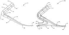
- the prosthetic foot 10can include an elongated, lower forefoot portion 12 and an elongated, upper forefoot portion 14 .
- the lower forefoot portion 12 and upper forefoot portion 14advantageously form resilient spring members to absorb shock during a walking gait or motion, and cushion the stump or limb of the amputee.
- the upper forefoot portion 14can be longer, or can extend past a termination of the lower forefoot portion 12 .
- the upper forefoot portion 14can include an upper attachment section 22 to be coupled to the limb or stump of the amputee.
- the upper forefoot portion 14can extend downwardly through the attachment section 22 , through an ankle section 26 , forwardly and downwardly through an arch section 30 , and forwardly to a toe section 34 .
- the upper attachment section 22 and the arch section 30can be substantially straight.
- the ankle section 26is positioned at an approximate ankle location of a natural foot.
- the toe section 34is positioned at an approximate toe location of a natural foot.
- the ankle locationis a region near the rearward end of the foot where an ankle of a natural foot would be located.
- arch, ball, and toe locationsare a regions near the middle and forward end of the foot where an arch, ball, toes of a natural foot would be located.
- the ankle section 26 of the upper forefoot portion 14can be substantially arcuate.
- the arc formed by the ankle sectioncan be smoothly curved, or can be formed of both straight and curved sections.
- the upper forefoot portion 14 or ankle 26forms a vertically oriented arc extending between the attachment section 22 and the arch or toe sections.
- the upper forefoot portion 14 or ankle section 26can form a curvilinear spring portion.
- the lower forefoot portion 12includes an upper attachment section 38 attached to the attachment section 22 of the upper forefoot portion 14 .
- the lower forefoot portion 12extends downwardly through the attachment section 38 , through an ankle section 42 , forwardly and downwardly past the arch section 46 to a terminal end 48 positioned at the approximate ball location of a natural foot.
- the attachment section 38 and the arch section 46can be substantially straight, and the ankle section 42 can be curved.
- the lower forefoot portion 12can be disposed under the upper forefoot portion 14 from at least the ankle section 42 to the terminal end 48 .
- the upper forefoot portion 14 and lower forefoot portioncan be positioned directly adjacent one another with no space or gap between the upper and lower forefoot portions, as shown in FIG. 1 .
- the upper forefoot portion 14 and lower forefoot portion 12can be spaced apart from one another such that a gap 16 can be formed between the upper and lower forefoot portions. As discussed below, the gap 16 can be filled with an energy storing material.
- the terminal end 48 of the lower forefoot portion 12can be positioned rearward of the toe section 34 of the upper forefoot portion 14 . In this way, the lower forefoot member terminates prior to the toe location.
- the lower forefoot portion 12is shorter than the upper forefoot portion 14 so that the upper forefoot portion can contact the ground at the toe location and the lower forefoot portion can contact the ground at the ball location between the arch location and the toe location.
- the lower forefoot memberhas longitudinal length between about 60% to 90% of a longitudinal length of the upper forefoot member; or between about 60% to 80% of a longitudinal length of the upper forefoot member in another aspect. In this way, the lower forefoot member 12 can extend from the ankle section 42 to a ball location of a natural foot, and the upper forefoot member 14 can extend from the ankle section 26 past the ball location to the toe location of a natural foot.
- the upper forefoot portion 14can contact a support surface, such as the ground, floor, inner shoe, lower forefoot, or the like at the toe section 34 .
- the lower forefoot portion 12can contact the ground at the terminal end 48 at or near the ball location.
- the toe section 34 of the upper forefoot 14 and the terminal end 48 of the lower forefoot 12can contact the support surface through an inside of a shoe, cosmetic shell, or the like.
- the arrangement of having the upper forefoot portion contact the support surface at the toe location and the lower forefoot portion contact the support surface at the ball locationprovides for a relatively stiffer resiliency through high load portions of a user's gait and also allows the foot to have a softer resiliency when the user assumes a terminal stance.
- both the upper forefoot portion 14 and the lower forefoot portion 12can contact the ground during a walking gait or step motion such that a lesser stiffness is felt by the user when only the upper forefoot portion 14 is contacting the ground, for example during a toe-off motion or toe standing position.
- a greater stiffnessis felt by the user when both the upper forefoot portion 14 and the lower forefoot portion 12 are contacting the ground together.
- the toe section 34 of the upper forefoot portion 14can be the only section contacting the ground and, thus, a lesser resistance or softer resiliency can be felt by the user.
- the pair of longer and shorter forefoot membersprovides multiple axes of rotation of the resilient spring members making up the upper and lower forefoot portions.
- the combined forefoot membershave a first axis of rotation while the upper forefoot member alone has a different second axis of rotation.
- multiple axes of rotationprovide a more natural feel of the prosthetic foot as the user moves through a walking or running motion.
- the attachment section 22 and the arch section 30 of the upper forefoot portion 14can be relatively straight or linear, and can extend forwardly and rearwardly, or in a posterior and anterior direction.
- the attachment section 38 and the partial arch section 46 of the lower forefoot portioncan be relatively straight or linear, and can extend forwardly and rearwardly, or in a posterior and anterior direction.
- Curved or angled sectionscan be formed between the straight sections.
- the straight and curved sectionscan provide multiple spring elements.
- the entire foot 10 , or the upper forefoot portion 14 and lower forefoot portion 12can be energy-storing members that flex and bend under a load to store energy.
- the energy storing memberscan also be resilient such that the members can return to an original configuration when the load on the foot is released to release the stored energy.
- the arch section 30can displace towards the ankle section 26 of the upper forefoot portion 14 .
- the partial arch section 46can displace towards the ankle section 42 of the lower forefoot portion 12 .
- the lower forefoot portion 12 and upper forefoot portion 14can provide vertical shock absorption in that the lower forefoot portion 12 and upper forefoot portion 14 can compress to absorb shock and/or loading in order to provide a cushion during use.
- the upper forefoot portion 14 and the lower forefoot portion 12can include or be formed of a flexible and resilient material.
- the materialcan be a composite with fibers disposed in a resin matrix.
- the fibercan be disposed in unidirectional, mat or weave with several layers.
- the upper forefoot portion 14 and the lower forefoot portion 12can deflect.
- the upper forefoot portion 14 and lower forefoot portion 12are made of a resilient material, the upper forefoot portion 14 and the lower forefoot portion 12 can act as a spring, and store the energy to be released as the user moves forward.
- the upper and lower forefoot portions 14 and 12respectively are made of a resilient material the upper and lower forefoot portions can return to an original shape.
- the foot 10can also include an attachment member (not shown) to attach the upper forefoot portion 14 to a socket configured for the specific needs of the amputee.
- the attachment membercan be coupled to either or both of the attachment sections 22 and 38 of the upper forefoot portion 14 and the lower forefoot portion 12 .
- Such socketstypically have a portion adapted for standard attachment. It is of course understood that any type of suitable fastener or connection can be used to couple the attachment member to the attachment sections 22 and 38 , including for example, screws, clips, etc.
- the attachment sections 22 and 38can be oblique, or can be disposed at an oblique angle with respect to a support surface or the stump of an amputee.
- the attachment membercan include a lower oblique surface.
- the attachment sections 22 and 38 of the forefoot and ankle portions 14 and 12can include an upper oblique surface 72 that can match and attach to the lower oblique surface.
- the attachment sections 22 and 38can be vertically oriented or horizontally oriented with respect to a support surface.
- the upper and lower oblique surfacescan be oblique or oriented at an oblique angle.
- the attachment sections 22 and 38can be oriented between approximately 20 and 70 degrees with respect to a horizontal axis. In another aspect, the attachment sections 22 and 38 can be oriented between approximately 30 and 60 degrees with respect to a horizontal axis. In another aspect, the attachment sections 22 and 38 can be oriented at approximately 45 degrees with respect to a horizontal axis, as shown in FIG. 1 .
- a prosthetic foot deviceindicated generally at 100 , in accordance with another embodiment of the present invention is shown for absorbing shock and cushioning a limb or stump of an amputee.
- the prosthetic foot device 100can be similar in many respects to the foot device 10 described above and shown in FIG. 1 .
- the prosthetic foot device 100can have an elongated lower forefoot portion 112 and an elongated, upper forefoot portion 14 .
- the prosthetic foot devicecan have an energy transfer member 150 disposed between the arch section 30 of the upper forefoot portion and the terminal end 148 of the lower forefoot portion.
- the energy transfer member 150can compress as the lower forefoot portion 112 flexes or displaces during use in order to cushion or absorb loading between the upper forefoot portion and the lower forefoot portion.
- the energy transfer member 150can variably transfer energy from the lower forefoot portion 112 to the upper forefoot portion 14 , ranging from a small amount of energy during small deflections, to a large amount of energy during large deflections.
- the energy transfer member 150can include a foam material, compressible bladders, pistons, variable viscosity fluid, or the like.
- the energy transfer member 150can also provide extra strength and extra stiffness for strenuous activities.
- a prosthetic foot deviceindicated generally at 200 , in accordance with another embodiment of the present invention is shown for absorbing shock and cushioning a limb or stump of an amputee.
- the prosthetic foot device 200can be similar in many respects to the foot device 10 described above and shown in FIG. 1 , or the prosthetic foot device 100 described above and shown in FIG. 2 .
- the prosthetic foot device 200can have an elongated lower forefoot portion 12 and an elongated, upper forefoot portion 14 .
- the prosthetic foot device 200can have a primary elongated ankle portion 212 and a secondary elongated ankle portion 214 .
- the primary elongated ankle portion 212extends rearwardly and downwardly through an attachment section 222 , downwardly through an ankle section 226 , forwardly and downwardly through an intermediate section 246 under the ankle section 42 of the lower forefoot portion 12 , and rearwardly and downwardly through a heel section 250 .
- the heel section 250is positioned at a heel location of a natural heel.
- the ankle portion 212can have a generally or substantially s-shaped profile.
- the attachment section 222 and the ankle section 226 of the ankle portion 212can match and abut to the attachment section 38 and ankle section 42 of the lower forefoot portion 12 .
- the secondary elongated ankle portion 214can reinforce the primary ankle portion 212 and provide extra strength and/or extra stiffness for strenuous activities.
- the secondary ankle portion 214 or reinforcement membercan be disposed adjacent or proximate to the primary ankle portion 212 .
- the secondary ankle portion 214can extend rearwardly through an upper attachment section 238 attached to the attachment section 22 of the upper forefoot portion 14 , downwardly through an ankle section 242 , forwardly under the ankle section 226 of the primary ankle portion 212 , and rearwardly to a heel section 260 positioned above the heel section 250 of the primary ankle portion 212 .
- the secondary ankle portion 214 or reinforcement membercan be engaged.
- the stiffness or strength of the primary ankle portion and the secondary ankle portioncan be configured so that the heel section 250 of the primary ankle portion 212 contacts or engages the heel section 260 of the secondary ankle portion 214 based on the user's body weight, such as at 1 gravity.
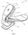
- a prosthetic foot deviceindicated generally at 300 , in accordance with another embodiment of the present invention is shown for absorbing shock and cushioning a limb or stump of an amputee.
- the prosthetic foot device 300can be similar in many respects to the foot device 200 described above and shown in FIGS. 3-6 .
- the prosthetic foot device 300can have an elongated lower forefoot portion 12 , an elongated, upper forefoot portion 14 , a primary elongated ankle portion 212 , and a secondary elongated ankle portion 214 .
- the prosthetic foot device 300can include a lower footplate 318 .
- the lower footplate 318can be disposed under the lower forefoot portion 12 and the upper forefoot portion 14 , and can extend a length of the foot from the heel to the toe.
- the lower footplate 318can be attached to the rear ankle portion 212 .
- the lower footplate 318can include a heel section 356 attached to the heel section 250 of the primary ankle portion 212 .
- the attachment of the lower footplate 318 to the primary ankle portion 212can form the primary or only attachment of the footplate 318 to the prosthetic foot 300 .
- the attachment 370can be formed by wrapping the heel sections 250 and 356 with fibers in a resin matrix.
- the lower footplate 318can extend forwardly through the heel section 356 , through an arch section 357 , and to a toe section 358 .
- the heel section 356is disposed at a heel location of a natural foot.
- toe section 358is positioned at a toe location of a natural foot.
- a gapcan be formed between the toe section 358 of the lower footplate 318 and the toe section 34 of the upper forefoot 14 so that the toe sections 34 and 358 are not positively or directly attached.
- a cushion member(not shown) can be disposed between the toe sections 34 and 358 .
- the cushion membercan be formed of a flexible material that can compress as the toe section 358 of the lower footplate 318 moves towards the toe section 34 of the upper forefoot 14 .
- FIG. 8another prosthetic foot device, indicated generally at 400 , in accordance with another embodiment of the present invention is shown for absorbing shock and cushioning a limb or stump of an amputee.
- the prosthetic foot device 400can be similar in many respects to the foot devices described above.
- the prosthetic foot device 400can have an elongated lower forefoot portion 412 , an elongated, upper forefoot portion 14 .
- the terminal end 448 of the lower forefoot portion 412can be positioned rearward of the toe section 34 of the upper forefoot portion 14 . In this way, the lower forefoot member terminates prior to the toe location.
- the terminal end 448can terminate at an angle with respect to a longitudinal axis of the foot such that one side of the lower forefoot portion 412 , such as the medial side 404 , is longer than the other side, such as the lateral side 408 .
- the terminal end 448can form a non-orthogonal or non-perpendicular angle with respect to the longitudinal axis.
- the lower forefoot portion 412 and the angled terminal end 448can provide greater stiffness on one side, such as the side corresponding to the big toe. It will be appreciated that the angled terminal end 448 of the foot device 400 shown in FIG. 8 can be applied to the other embodiments described herein.
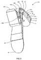
- FIG. 9another prosthetic foot device, indicated generally at 500 , in accordance with another embodiment of the present invention is shown for absorbing shock and cushioning a limb or stump of an amputee.
- the prosthetic foot device 500can be similar in many respects to the foot devices described above.
- the prosthetic foot device 500can have an elongated lower forefoot portion 512 , an elongated, upper forefoot portion 514 .
- the terminal end 548 of the lower forefoot portion 512can be positioned rearward of the toe section 34 of the upper forefoot portion 514 . In this way, the lower forefoot member terminates prior to the toe location.
- the foot 500 , or the upper and lower forefoot portions 514 and 512can be configured for a lower profile that is more horizontal and which extend forwardly from an attachment section 522 and 538 , and down and forward through an arch section.
- the terminal end of the shorter lower footplatecan have an angled cut to be more tapered at the end and fit better between the upper footplate and the ground. Additionally, a cosmetic shell, or comesis, can be disposed around the feet described above.
Landscapes
- Health & Medical Sciences (AREA)
- Transplantation (AREA)
- Biomedical Technology (AREA)
- Cardiology (AREA)
- Oral & Maxillofacial Surgery (AREA)
- Engineering & Computer Science (AREA)
- Orthopedic Medicine & Surgery (AREA)
- Heart & Thoracic Surgery (AREA)
- Vascular Medicine (AREA)
- Life Sciences & Earth Sciences (AREA)
- Animal Behavior & Ethology (AREA)
- General Health & Medical Sciences (AREA)
- Public Health (AREA)
- Veterinary Medicine (AREA)
- Prostheses (AREA)
Abstract
Description
Claims (19)
Priority Applications (3)
| Application Number | Priority Date | Filing Date | Title |
|---|---|---|---|
| US11/999,734US7824446B2 (en) | 2006-12-06 | 2007-12-05 | Prosthetic foot with longer upper forefoot and shorter lower forefoot |
| EP07853281.9AEP2088968B1 (en) | 2006-12-06 | 2007-12-06 | Prosthetic foot with longer upper forefoot and shorter lower forefoot |
| PCT/US2007/025060WO2008070177A1 (en) | 2006-12-06 | 2007-12-06 | Prosthetic foot with longer upper forefoot and shorter lower forefoot |
Applications Claiming Priority (2)
| Application Number | Priority Date | Filing Date | Title |
|---|---|---|---|
| US87340206P | 2006-12-06 | 2006-12-06 | |
| US11/999,734US7824446B2 (en) | 2006-12-06 | 2007-12-05 | Prosthetic foot with longer upper forefoot and shorter lower forefoot |
Publications (2)
| Publication Number | Publication Date |
|---|---|
| US20080167731A1 US20080167731A1 (en) | 2008-07-10 |
| US7824446B2true US7824446B2 (en) | 2010-11-02 |
Family
ID=39492569
Family Applications (1)
| Application Number | Title | Priority Date | Filing Date |
|---|---|---|---|
| US11/999,734Expired - Fee RelatedUS7824446B2 (en) | 2006-12-06 | 2007-12-05 | Prosthetic foot with longer upper forefoot and shorter lower forefoot |
Country Status (3)
| Country | Link |
|---|---|
| US (1) | US7824446B2 (en) |
| EP (1) | EP2088968B1 (en) |
| WO (1) | WO2008070177A1 (en) |
Cited By (17)
| Publication number | Priority date | Publication date | Assignee | Title |
|---|---|---|---|---|
| US8034121B2 (en) | 2008-04-18 | 2011-10-11 | Freedom Innovations, Llc | Prosthetic foot with two leaf-springs joined at heel and toe |
| US8500825B2 (en) | 2010-06-29 | 2013-08-06 | Freedom Innovations, Llc | Prosthetic foot with floating forefoot keel |
| US20130261767A1 (en)* | 2012-03-27 | 2013-10-03 | Medi Gmbh & Co Kg | Foot prosthesis |
| US9017421B2 (en) | 2011-12-01 | 2015-04-28 | össur hf | Prosthetic foot with dual foot blades and vertically offset toe |
| US9028559B2 (en) | 2011-09-26 | 2015-05-12 | össur hf | Frictionless vertical suspension mechanism for prosthetic feet |
| US9078773B2 (en) | 2007-09-19 | 2015-07-14 | Ability Dynamics Llc | Prosthetic foot |
| US9439786B2 (en) | 2012-08-01 | 2016-09-13 | össur hf | Prosthetic ankle module |
| US9561118B2 (en) | 2013-02-26 | 2017-02-07 | össur hf | Prosthetic foot with enhanced stability and elastic energy return |
| US20170035583A1 (en)* | 2014-05-07 | 2017-02-09 | Otto Bock Healthcare Gmbh | Method for connecting at least two structural parts of an orthopedic component and orthopedic component having at least two structural parts |
| USD795433S1 (en) | 2015-06-30 | 2017-08-22 | Össur Iceland Ehf | Prosthetic foot cover |
| USD797292S1 (en) | 2014-06-30 | 2017-09-12 | össur hf | Prosthetic foot plate |
| US9999525B2 (en) | 2015-01-15 | 2018-06-19 | Ability Dynamics, Llc | Prosthetic foot |
| US10405998B2 (en) | 2007-09-19 | 2019-09-10 | Ability Dynamics Llc | Mounting bracket for connecting a prosthetic limb to a prosthetic foot |
| USD909582S1 (en)* | 2018-08-29 | 2021-02-02 | Xiborg Inc. | Prosthetic |
| USD915596S1 (en) | 2018-04-10 | 2021-04-06 | Össur Iceland Ehf | Prosthetic foot with tapered fasteners |
| US11020248B2 (en) | 2007-09-19 | 2021-06-01 | Proteor USA, LLC | Vacuum system for a prosthetic foot |
| US12011373B2 (en) | 2007-09-19 | 2024-06-18 | Proteor USA, LLC | Mounting bracket for connecting a prosthetic limb to a prosthetic foot |
Families Citing this family (7)
| Publication number | Priority date | Publication date | Assignee | Title |
|---|---|---|---|---|
| EP2522311B1 (en)* | 2009-11-25 | 2016-07-06 | Otto Bock HealthCare GmbH | Prosthetic foot |
| EP2632392B1 (en) | 2010-10-25 | 2015-06-03 | Otto Bock HealthCare GmbH | Prosthetic foot |
| US9974666B2 (en) | 2010-10-25 | 2018-05-22 | Otto Bock Healthcare Gmbh | Prosthetic foot |
| DE102010049257B4 (en)* | 2010-10-25 | 2015-05-07 | Otto Bock Healthcare Gmbh | prosthetic |
| JP6333945B2 (en)* | 2013-03-18 | 2018-05-30 | セー・リンデエクステンド・アーベー | Prosthetic foot device |
| DE102014006571B3 (en)* | 2014-05-07 | 2015-08-06 | Otto Bock Healthcare Gmbh | prosthetic |
| US20160038311A1 (en)* | 2014-08-08 | 2016-02-11 | Board Of Regents, The University Of Texas System | Layering technique for an adjustable, repairable variable stiffness prosthetic foot |
Citations (153)
| Publication number | Priority date | Publication date | Assignee | Title |
|---|---|---|---|---|
| DE295807C (en)* | ||||
| US42799A (en) | 1864-05-17 | Improvement in artificial legs | ||
| US92031A (en) | 1869-06-29 | Improved artificial leg | ||
| US292800A (en) | 1884-02-05 | Artificial leg | ||
| US497026A (en) | 1893-05-09 | Artificial limb | ||
| US1001641A (en) | 1909-03-17 | 1911-08-29 | John Waddell | Ankle-joint. |
| US1289580A (en) | 1918-04-05 | 1918-12-31 | Stanislaw Vincenti | Artificial foot. |
| US1779765A (en) | 1926-09-21 | 1930-10-28 | Firm Of F L Fischer | Artificial-foot joint |
| US1996874A (en) | 1932-08-31 | 1935-04-09 | Mascau Emile Desire | Articulated ankle joint for artificial feet |
| US2036830A (en) | 1934-08-13 | 1936-04-07 | James F Rowley | Artificial foot |
| US2379538A (en) | 1942-09-09 | 1945-07-03 | Meierhofer Max | Joint for leg supports and artificial limbs in general |
| US2443356A (en) | 1946-04-02 | 1948-06-15 | John H Mathis | Flexible joint for artificial limbs |
| US2453969A (en) | 1947-04-03 | 1948-11-16 | Edwin C Carter | Artificial limb |
| US2470480A (en) | 1946-04-23 | 1949-05-17 | Stanley R Fogg | Artificial foot |
| US2570735A (en) | 1949-03-18 | 1951-10-09 | Carl A Weise | Flexible joint for artificial limbs |
| US2617115A (en) | 1949-07-25 | 1952-11-11 | Emmett C Ellery | Ankle joint for artificial legs |
| US2640200A (en) | 1950-07-28 | 1953-06-02 | Wisbrun Walter | Prosthesis construction |
| US2843853A (en) | 1956-11-26 | 1958-07-22 | Hans A Mauch | Control mechanism for artificial ankle |
| US3206235A (en) | 1962-08-30 | 1965-09-14 | Miller Herman Inc | Adjustable foot piece |
| GB1191633A (en) | 1966-06-14 | 1970-05-13 | J E Hanger And Company Ltd | Improvements in Artificial Limbs and Splints |
| US3548420A (en) | 1967-03-06 | 1970-12-22 | Stryker Corp | Cushion structure |
| US3551914A (en) | 1968-05-09 | 1971-01-05 | Carl Woodall | Natural action toe lift artificial foot |
| US3754286A (en) | 1972-01-21 | 1973-08-28 | M Ryan | Artificial foot having ankle flexible mount |
| US3858379A (en) | 1970-06-09 | 1975-01-07 | Us Army | Process for making a polyvinyl alcohol gel support pad |
| US3871032A (en) | 1974-03-08 | 1975-03-18 | Forsch Orthopadie Technik | Artificial hydraulic ankle joint |
| US3874004A (en) | 1973-05-31 | 1975-04-01 | Hanger & Co Ltd J E | Symes ankle joint |
| US3906552A (en) | 1972-08-30 | 1975-09-23 | Watkins Lloyd J | Pivot joint adapter |
| US3920610A (en) | 1973-02-28 | 1975-11-18 | Eugene Wagner | Method of making and tailoring prosthetic feet |
| US3956775A (en) | 1975-02-18 | 1976-05-18 | Moore Robert R | Rotator for prosthetic ankle joint |
| US3982280A (en) | 1973-05-03 | 1976-09-28 | The United States Of America As Represented By The Secretary Of The Navy | Functional ankle for a prosthetic limb |
| SU560606A1 (en) | 1975-07-18 | 1977-06-05 | Центральный Ордена Трудового Красного Знамени Научно-Исследовательский Институт Протезирования И Протезостроения | Artificial foot |
| US4089072A (en) | 1975-07-18 | 1978-05-16 | Otto Bock Orthopadische Industrie K.G. | Prosthetic appliance |
| GB1550658A (en) | 1977-11-16 | 1979-08-15 | Hanger & Co Ltd J E | Artificial limbs |
| US4328594A (en) | 1980-02-13 | 1982-05-11 | Campbell John W | Prosthetic foot |
| US4442554A (en) | 1982-02-12 | 1984-04-17 | Arthur Copes | Biomechanical ankle device |
| US4506395A (en) | 1983-03-18 | 1985-03-26 | Otto Bock Orthopadische Industrie Kg | Prosthetic foot |
| US4547913A (en) | 1983-07-11 | 1985-10-22 | Flex Foot, Inc. | Composite prosthetic foot and leg |
| US4606332A (en) | 1984-09-10 | 1986-08-19 | Gibson Howard W | Back treatment apparatus |
| US4636220A (en) | 1986-01-14 | 1987-01-13 | John W. Campbell | Adjustable prosthetic foot |
| US4645509A (en) | 1984-06-11 | 1987-02-24 | Model & Instrument Development Corporation | Prosthetic foot having a cantilever spring keel |
| US4676800A (en) | 1986-06-02 | 1987-06-30 | Chen Sen J | Adjustable device for artificial limbs |
| US4676801A (en) | 1983-05-23 | 1987-06-30 | Orthopedic Specialties, Inc. | Foot orthosis and process |
| US4721510A (en) | 1986-02-28 | 1988-01-26 | J. E. Hanger & Company, Limited | Artificial foot |
| US4764172A (en) | 1986-11-28 | 1988-08-16 | Mccoy Allen J | Articulated ankle |
| US4822363A (en) | 1985-08-01 | 1989-04-18 | Phillips L Van | Modular composite prosthetic foot and leg |
| US4865612A (en) | 1986-07-28 | 1989-09-12 | The Ohio Willow Wood Company, Inc. | Prosthetic foot |
| US4865611A (en) | 1988-05-16 | 1989-09-12 | Al Turaiki Mohammed H S | Lockable rotating ankle joint for modular below-knee prosthesis |
| US4892553A (en)* | 1988-03-29 | 1990-01-09 | Ipos Gmbh & Co, Kg | Artificial foot for a leg prosthesis |
| US4938775A (en) | 1989-04-03 | 1990-07-03 | Morgan Robert D | Artificial leg with bearings for rotational motion |
| US4959073A (en) | 1988-06-06 | 1990-09-25 | John Merlette | Foot prosthesis and method of making same |
| US5007938A (en)* | 1989-07-08 | 1991-04-16 | Ipos Gmbh & Co. Kg | Artificial foot for a leg prosthesis |
| US5019109A (en) | 1990-03-09 | 1991-05-28 | Voisin Jerome P | Multi-axial rotation system for artificial ankle |
| US5030239A (en) | 1982-02-12 | 1991-07-09 | Copes, Inc. | Biomechanical ankle |
| US5037444A (en) | 1989-01-05 | 1991-08-06 | Phillips L Van | Prosthetic foot |
| US5062859A (en) | 1989-06-09 | 1991-11-05 | Otto Bock Orthopaedische Industrie Besitz- und Verwaltungs-Kommanditgesel lschaft | Prosthetic foot having z shaped insert |
| US5112356A (en) | 1988-03-04 | 1992-05-12 | Chas A. Blatchford & Sons Limited | Lower limb prosthesis with means for restricting dorsi-flexion |
| US5116384A (en) | 1990-08-31 | 1992-05-26 | Syncor, Ltd. | Prosthetic foot |
| US5116383A (en) | 1988-03-04 | 1992-05-26 | Chas. A. Blatchford & Sons Ltd. | Lowelimb prothesis |
| US5156632A (en) | 1990-11-29 | 1992-10-20 | Otto Bock Orthopaedische Industrie Besitz- und Verwaltungs-Kommanditgesel lschaft | Jointless prosthetic foot |
| US5181932A (en) | 1989-04-13 | 1993-01-26 | Phillips L Van | Foot prosthesis having auxiliary ankle construction |
| US5181933A (en) | 1991-02-28 | 1993-01-26 | Phillips L Van | Split foot prosthesis |
| US5217500A (en) | 1990-01-12 | 1993-06-08 | Phillips L Van | Prosthetic leg |
| US5219365A (en) | 1988-03-31 | 1993-06-15 | Sabolich, Inc. | Prosthetic foot |
| US5258039A (en) | 1991-11-15 | 1993-11-02 | The National University Of Singapore | Energy storing composite prosthetic foot |
| US5267633A (en) | 1991-02-15 | 1993-12-07 | Bridgestone Corporation | Electrorheological fluid-applied apparatus, electrorheological fluid-applied vibration controller, and electrorheological fluid-applied fixing apparatus |
| US5290319A (en) | 1991-02-28 | 1994-03-01 | Phillips L Van | Prosthetic foot incorporating adjustable bladders |
| US5314499A (en) | 1991-04-04 | 1994-05-24 | Collier Jr Milo S | Artificial limb including a shin, ankle and foot |
| GB2244006B (en) | 1990-05-04 | 1994-05-25 | Blatchford & Sons Ltd | An artificial limb |
| US5376141A (en) | 1990-09-21 | 1994-12-27 | Phillips; Van L. | Low-profile symes foot prosthesis |
| US5376139A (en) | 1992-09-21 | 1994-12-27 | Pitkin; Mark R. | Artificial foot and ankle |
| US5376133A (en) | 1990-04-02 | 1994-12-27 | Gramnaes; Finn | An adjustable resilient foot prosthesis |
| US5387246A (en) | 1989-04-13 | 1995-02-07 | Phillips; Van L. | Prosthetic ski leg |
| US5405411A (en) | 1992-04-01 | 1995-04-11 | Mccoy; Allen J. | Articulated ankle joint with inner and outer races for universal movement |
| RU2033772C1 (en) | 1990-11-06 | 1995-04-30 | Санкт-Петербургский научно-исследовательский институт протезирования | Rotation-damping unit of artificial lower extremities |
| BR9304225A (en) | 1993-10-13 | 1995-06-06 | Giuseppe Capulli | Hot gas collector |
| US5425782A (en) | 1992-03-11 | 1995-06-20 | Phillips; Van L. | Alignment fixture for prosthetic device |
| US5425781A (en) | 1994-01-14 | 1995-06-20 | Universite De Montreal | Ankle connector for prosthetic foot |
| BR9304552A (en) | 1993-11-22 | 1995-07-11 | Luccia Nelson De | Prosthesis for lower limb amputees |
| US5443528A (en) | 1992-11-17 | 1995-08-22 | Allen; Scott | Coil spring prosthetic foot |
| US5443529A (en) | 1991-02-28 | 1995-08-22 | Phillips; Van L. | Prosthetic device incorporating multiple sole bladders |
| US5458656A (en) | 1991-09-30 | 1995-10-17 | Flex-Foot | Energy-storing prosthesis leg pylon vertical shock leg |
| US5482513A (en) | 1993-03-31 | 1996-01-09 | Wilson Michael T | Ankle joint with dedicated transverse rotator |
| US5507838A (en) | 1994-01-27 | 1996-04-16 | Chen; Sen-Jung | Artificial foot with members to help wearer maintain steady balance |
| US5509936A (en) | 1994-06-30 | 1996-04-23 | Rappoport; Albert F. | Dual leaf spring strut system |
| US5509937A (en) | 1994-01-14 | 1996-04-23 | Universite De Montreal | Prosthetic foot with enhanced heel control |
| US5514186A (en) | 1989-04-13 | 1996-05-07 | Phillips; Van L. | Attachment construction for prosthesis |
| US5549714A (en) | 1990-09-21 | 1996-08-27 | Phillips; Van L. | Symes foot prosthesis |
| US5571210A (en) | 1992-06-02 | 1996-11-05 | Pro-Pel Ab | Adjustable foot prosthesis |
| US5593456A (en) | 1994-05-17 | 1997-01-14 | Crp, Inc. | Foot and leg prosthesis and method of making same |
| US5593455A (en) | 1994-05-27 | 1997-01-14 | Phillips; Van L. | Plug mounted prosthesis |
| US5653767A (en) | 1992-11-17 | 1997-08-05 | Medonics, Llc | Prosthetic foot |
| US5653768A (en) | 1994-01-21 | 1997-08-05 | Bruce Kania | Dual cantilevered leaf spring structure |
| US5728175A (en) | 1995-10-03 | 1998-03-17 | Rincoe; Richard G. | Artificial ankle joint with cushion structures and prosthetic devices formed therewith |
| US5728177A (en) | 1994-08-15 | 1998-03-17 | Flex-Foot, Inc. | Prosthesis with foam block ankle |
| US5746774A (en) | 1994-09-09 | 1998-05-05 | The University Of Toledo | Knee joint mechanism for knee disarticulation prosthesis |
| US5766265A (en) | 1985-08-01 | 1998-06-16 | Phillips; Van L. | Prosthetic foot having curved integral support |
| US5766704A (en) | 1995-10-27 | 1998-06-16 | Acushnet Company | Conforming shoe construction and gel compositions therefor |
| US5769896A (en) | 1994-09-30 | 1998-06-23 | Brent Rosendahl | Prosthetic foot with ankle |
| US5779735A (en) | 1996-05-17 | 1998-07-14 | Molino; Joseph L. | Knee unit for above-knee prosthetic leg |
| US5800565A (en) | 1994-05-25 | 1998-09-01 | Biedermann Motech Gmbh | Leg prosthesis with quick exchange and displacement adjustment connections |
| US5800564A (en) | 1995-09-18 | 1998-09-01 | Gelineau; Roger | Ankle prosthesis with angle adjustment |
| US5824112A (en) | 1989-04-13 | 1998-10-20 | Phillips; Van L. | Prosthetic device incorporating low ankle design |
| US5888239A (en)* | 1995-06-09 | 1999-03-30 | Otto Bock Orthopaedische Industrie Besitz-Und Verwaltungs-Kommanditge-Sel lschaft | Jointless foot prosthesis |
| US5893891A (en) | 1993-06-11 | 1999-04-13 | Chas. A. Blatchford & Sons Limited | Prosthesis control system |
| US5899944A (en) | 1991-02-28 | 1999-05-04 | Phillips; Van L. | Prosthetic foot incorporating compressible members |
| US5913902A (en) | 1996-09-30 | 1999-06-22 | Geible; Harry F. | Artificial foot that enables Limp-free walking |
| US5944760A (en) | 1997-08-04 | 1999-08-31 | Roland J. Christensen Family Limited Partnership | Prosthetic foot with reinforcing member |
| US5957981A (en) | 1995-02-21 | 1999-09-28 | Gramtec Innovation Ab | Adjustable prosthesis joint |
| US6007582A (en) | 1996-03-29 | 1999-12-28 | Ortho Europe Limited | Prosthetic foot with means for energy storage and release |
| US6071313A (en) | 1991-02-28 | 2000-06-06 | Phillips; Van L. | Split foot prosthesis |
| US6077301A (en) | 1997-04-24 | 2000-06-20 | Otto Bock Orthopaedische Industrie Besitz- und Verwaltungs-Kommandit-Gese llschaft | Resilient foot insert for an artificial foot |
| US6099572A (en) | 1997-04-24 | 2000-08-08 | Otto Bock Orthopaedishche Industrie Besitz- Und Verwaltungs- Kommandit- Gesellschaft | Resilient foot insert |
| US6120547A (en) | 1998-11-06 | 2000-09-19 | Roland J. Christensen | Enhanced prosthetic foot structure with ankle reinforcement |
| US6187052B1 (en) | 1999-07-14 | 2001-02-13 | Joseph L. Molino | Prosthetic ankle joint |
| US6197068B1 (en) | 1997-08-04 | 2001-03-06 | Roland J. Christensen | Prosthetic foot simulating toe rotation |
| US6206934B1 (en) | 1998-04-10 | 2001-03-27 | Flex-Foot, Inc. | Ankle block with spring inserts |
| US6228124B1 (en) | 1997-09-08 | 2001-05-08 | Prosthetic Design, Inc. | Prosthetic foot with lateral and angular adjustability |
| US6241776B1 (en) | 1997-08-04 | 2001-06-05 | Roland Christensen | Prosthetic foot with reinforcing member |
| US6261324B1 (en) | 1999-05-26 | 2001-07-17 | Crp, Inc. | Foot prosthesis |
| US6290730B1 (en) | 1999-03-26 | 2001-09-18 | Ohio Willow Wood Company | Artificial foot and ankle |
| US6306178B1 (en) | 1998-10-22 | 2001-10-23 | Fountainhead | Prosthetic device using a cam-shaped wheel |
| EP1149568A1 (en) | 2000-04-26 | 2001-10-31 | CHAS. A. BLATCHFORD & SONS LIMITED | Adaptable prosthetic foot |
| US6402790B1 (en) | 2000-07-20 | 2002-06-11 | Dogan Celebi | Angularly adjustable reversible prosthetic device |
| US6406500B1 (en) | 1989-04-13 | 2002-06-18 | Van L. Phillips | Foot prosthesis having curved forefoot |
| US20020077706A1 (en) | 2000-08-30 | 2002-06-20 | Phillips Van L. | Energy storing foot prosthesis with improved plantar flexion |
| US6443993B1 (en) | 2001-03-23 | 2002-09-03 | Wayne Koniuk | Self-adjusting prosthetic ankle apparatus |
| US6443995B1 (en) | 2000-12-22 | 2002-09-03 | Barry W. Townsend | Prosthetic foot |
| US20020133237A1 (en) | 2000-06-30 | 2002-09-19 | Christesen Roland J. | Prosthetic foot with energy transfer medium including variable viscosity fluid |
| WO2003003953A1 (en) | 2001-07-06 | 2003-01-16 | University Of Reading | Rotatable joint stop mechanism |
| US20030019540A1 (en) | 2001-07-26 | 2003-01-30 | Ibm Corporation | Electromechanical device and a process of preparing same |
| US6514293B1 (en) | 2000-04-03 | 2003-02-04 | Korea Advanced Institute Of Science And Technology | Prosthetic foot |
| US20030045944A1 (en) | 2000-10-07 | 2003-03-06 | Luder Mosler | Foot insert for an artificial foot |
| US6562075B2 (en) | 2001-03-30 | 2003-05-13 | Barry W. Townsend | Prosthetic foot with tunable performance |
| US6596029B1 (en) | 1999-07-09 | 2003-07-22 | Gramtec Innovation Ab | Foot prosthesis |
| US6602295B1 (en) | 1999-05-24 | 2003-08-05 | Ohio Willow Wood Company | Prosthetic foot having shock absorption |
| US6676708B1 (en) | 2002-08-22 | 2004-01-13 | Aldo A. Laghi | Prosthetic foot with differentiated heel elasticity and split upper ankle |
| US20040068326A1 (en) | 2002-10-08 | 2004-04-08 | Christensen Roland J. | Prosthetic foot with oblique attachment |
| US6740125B2 (en) | 2002-03-28 | 2004-05-25 | Otto Bock Healthcare Gmbh | Knee-joint prosthesis with a hydraulic damping cylinder |
| US6793683B1 (en) | 2002-08-22 | 2004-09-21 | Aldo A. Laghi | Prosthetic foot with medial/lateral stabilization |
| US6805717B2 (en) | 2002-10-08 | 2004-10-19 | Roland J. Christensen, As Operating Manager Of Rjc Development, Lc, General Manager Of The Roland J. Christensen Family Limited Partnership | Energy-storing prosthetic foot with elongated forefoot |
| US20050049721A1 (en) | 2003-08-29 | 2005-03-03 | Sulprizio Michael Scott | Wideband CDMA mobile device initial frequency offset acquisition |
| US6869451B1 (en) | 2002-08-23 | 2005-03-22 | Aldo A. Laghi | Dynamic prosthetic foot with multiple load points and multiple upper sections |
| US6875241B2 (en) | 2000-06-30 | 2005-04-05 | Roland J. Christensen, As Operating Manager Of Rjc Development Lc, General Partner Of The Roland J. Christensen Family Limited Partnership | Variable resistance cell |
| US6887279B2 (en) | 1998-04-10 | 2005-05-03 | össur hf | Active shock module prosthesis |
| US6929665B2 (en) | 2002-10-08 | 2005-08-16 | Roland J. Christensen | Prosthetic foot with a resilient ankle |
| US20050187640A1 (en) | 2004-02-20 | 2005-08-25 | Roland J. Christensen | Prosthetic foot with cam |
| US20050203640A1 (en) | 2002-10-08 | 2005-09-15 | Christensen Roland J. | Prosthetic foot with a resilient ankle |
| US6966933B2 (en) | 2003-10-21 | 2005-11-22 | Roland J. Christensen, As Operating Manager Of Rjc Development, Lc, General Partner Of The Roland J. Christensen Family Limited Partnership | Prosthetic foot with an adjustable ankle and method |
| US20060030950A1 (en) | 2001-03-30 | 2006-02-09 | Townsend Barry W | Prosthetic foot with tunable performance |
| EP1340478B1 (en) | 2002-02-28 | 2007-10-10 | Honda Giken Kogyo Kabushiki Kaisha | Parallel linkage and artificial joint device using the same |
| US7341603B2 (en) | 2000-06-30 | 2008-03-11 | Applied Composite Technology, Inc. | Prosthetic foot with energy transfer including variable orifice |
| US7347877B2 (en)* | 2004-05-28 | 2008-03-25 | össur hf | Foot prosthesis with resilient multi-axial ankle |
| US20090265019A1 (en) | 2008-04-18 | 2009-10-22 | Chritstensen Roland J | Prosthetic foot with two leaf-springs joined at heel and toe |
Family Cites Families (4)
| Publication number | Priority date | Publication date | Assignee | Title |
|---|---|---|---|---|
| US497023A (en)* | 1893-05-09 | Means for displaying advertisements | ||
| US1191633A (en)* | 1916-01-26 | 1916-07-18 | J H White Mfg Company | Resilient attachment for shade-holders. |
| US5514486A (en)* | 1995-09-01 | 1996-05-07 | The Regents Of The University Of California, Office Of Technology Transfer | Annular feed air breathing fuel cell stack |
| US7419509B2 (en)* | 2002-10-08 | 2008-09-02 | Freedom Innovations, Llc | Prosthetic foot with a resilient ankle |
- 2007
- 2007-12-05USUS11/999,734patent/US7824446B2/ennot_activeExpired - Fee Related
- 2007-12-06EPEP07853281.9Apatent/EP2088968B1/ennot_activeNot-in-force
- 2007-12-06WOPCT/US2007/025060patent/WO2008070177A1/enactiveApplication Filing
Patent Citations (176)
| Publication number | Priority date | Publication date | Assignee | Title |
|---|---|---|---|---|
| DE295807C (en)* | ||||
| US42799A (en) | 1864-05-17 | Improvement in artificial legs | ||
| US92031A (en) | 1869-06-29 | Improved artificial leg | ||
| US292800A (en) | 1884-02-05 | Artificial leg | ||
| US497026A (en) | 1893-05-09 | Artificial limb | ||
| US1001641A (en) | 1909-03-17 | 1911-08-29 | John Waddell | Ankle-joint. |
| US1289580A (en) | 1918-04-05 | 1918-12-31 | Stanislaw Vincenti | Artificial foot. |
| US1779765A (en) | 1926-09-21 | 1930-10-28 | Firm Of F L Fischer | Artificial-foot joint |
| US1996874A (en) | 1932-08-31 | 1935-04-09 | Mascau Emile Desire | Articulated ankle joint for artificial feet |
| US2036830A (en) | 1934-08-13 | 1936-04-07 | James F Rowley | Artificial foot |
| US2379538A (en) | 1942-09-09 | 1945-07-03 | Meierhofer Max | Joint for leg supports and artificial limbs in general |
| US2443356A (en) | 1946-04-02 | 1948-06-15 | John H Mathis | Flexible joint for artificial limbs |
| US2470480A (en) | 1946-04-23 | 1949-05-17 | Stanley R Fogg | Artificial foot |
| US2453969A (en) | 1947-04-03 | 1948-11-16 | Edwin C Carter | Artificial limb |
| US2570735A (en) | 1949-03-18 | 1951-10-09 | Carl A Weise | Flexible joint for artificial limbs |
| US2617115A (en) | 1949-07-25 | 1952-11-11 | Emmett C Ellery | Ankle joint for artificial legs |
| US2640200A (en) | 1950-07-28 | 1953-06-02 | Wisbrun Walter | Prosthesis construction |
| US2843853A (en) | 1956-11-26 | 1958-07-22 | Hans A Mauch | Control mechanism for artificial ankle |
| US3206235A (en) | 1962-08-30 | 1965-09-14 | Miller Herman Inc | Adjustable foot piece |
| GB1191633A (en) | 1966-06-14 | 1970-05-13 | J E Hanger And Company Ltd | Improvements in Artificial Limbs and Splints |
| US3548420A (en) | 1967-03-06 | 1970-12-22 | Stryker Corp | Cushion structure |
| US3551914A (en) | 1968-05-09 | 1971-01-05 | Carl Woodall | Natural action toe lift artificial foot |
| US3858379A (en) | 1970-06-09 | 1975-01-07 | Us Army | Process for making a polyvinyl alcohol gel support pad |
| US3754286A (en) | 1972-01-21 | 1973-08-28 | M Ryan | Artificial foot having ankle flexible mount |
| US3906552A (en) | 1972-08-30 | 1975-09-23 | Watkins Lloyd J | Pivot joint adapter |
| US3920610A (en) | 1973-02-28 | 1975-11-18 | Eugene Wagner | Method of making and tailoring prosthetic feet |
| US3982280A (en) | 1973-05-03 | 1976-09-28 | The United States Of America As Represented By The Secretary Of The Navy | Functional ankle for a prosthetic limb |
| US3874004A (en) | 1973-05-31 | 1975-04-01 | Hanger & Co Ltd J E | Symes ankle joint |
| US3871032A (en) | 1974-03-08 | 1975-03-18 | Forsch Orthopadie Technik | Artificial hydraulic ankle joint |
| US3956775A (en) | 1975-02-18 | 1976-05-18 | Moore Robert R | Rotator for prosthetic ankle joint |
| SU560606A1 (en) | 1975-07-18 | 1977-06-05 | Центральный Ордена Трудового Красного Знамени Научно-Исследовательский Институт Протезирования И Протезостроения | Artificial foot |
| US4089072A (en) | 1975-07-18 | 1978-05-16 | Otto Bock Orthopadische Industrie K.G. | Prosthetic appliance |
| GB1550658A (en) | 1977-11-16 | 1979-08-15 | Hanger & Co Ltd J E | Artificial limbs |
| US4328594A (en) | 1980-02-13 | 1982-05-11 | Campbell John W | Prosthetic foot |
| US4442554A (en) | 1982-02-12 | 1984-04-17 | Arthur Copes | Biomechanical ankle device |
| US5030239A (en) | 1982-02-12 | 1991-07-09 | Copes, Inc. | Biomechanical ankle |
| US4506395A (en) | 1983-03-18 | 1985-03-26 | Otto Bock Orthopadische Industrie Kg | Prosthetic foot |
| US4676801A (en) | 1983-05-23 | 1987-06-30 | Orthopedic Specialties, Inc. | Foot orthosis and process |
| US4547913A (en) | 1983-07-11 | 1985-10-22 | Flex Foot, Inc. | Composite prosthetic foot and leg |
| US4645509A (en) | 1984-06-11 | 1987-02-24 | Model & Instrument Development Corporation | Prosthetic foot having a cantilever spring keel |
| US4606332A (en) | 1984-09-10 | 1986-08-19 | Gibson Howard W | Back treatment apparatus |
| US4822363A (en) | 1985-08-01 | 1989-04-18 | Phillips L Van | Modular composite prosthetic foot and leg |
| US6019795A (en) | 1985-08-01 | 2000-02-01 | Phillips; Van L. | Curved prosthesis |
| US5766265A (en) | 1985-08-01 | 1998-06-16 | Phillips; Van L. | Prosthetic foot having curved integral support |
| US4636220A (en) | 1986-01-14 | 1987-01-13 | John W. Campbell | Adjustable prosthetic foot |
| US4721510A (en) | 1986-02-28 | 1988-01-26 | J. E. Hanger & Company, Limited | Artificial foot |
| US4676800A (en) | 1986-06-02 | 1987-06-30 | Chen Sen J | Adjustable device for artificial limbs |
| US4865612A (en) | 1986-07-28 | 1989-09-12 | The Ohio Willow Wood Company, Inc. | Prosthetic foot |
| US4764172A (en) | 1986-11-28 | 1988-08-16 | Mccoy Allen J | Articulated ankle |
| US5116383A (en) | 1988-03-04 | 1992-05-26 | Chas. A. Blatchford & Sons Ltd. | Lowelimb prothesis |
| US5112356A (en) | 1988-03-04 | 1992-05-12 | Chas A. Blatchford & Sons Limited | Lower limb prosthesis with means for restricting dorsi-flexion |
| US4892553A (en)* | 1988-03-29 | 1990-01-09 | Ipos Gmbh & Co, Kg | Artificial foot for a leg prosthesis |
| US5219365A (en) | 1988-03-31 | 1993-06-15 | Sabolich, Inc. | Prosthetic foot |
| US4865611A (en) | 1988-05-16 | 1989-09-12 | Al Turaiki Mohammed H S | Lockable rotating ankle joint for modular below-knee prosthesis |
| US4959073A (en) | 1988-06-06 | 1990-09-25 | John Merlette | Foot prosthesis and method of making same |
| US5037444A (en) | 1989-01-05 | 1991-08-06 | Phillips L Van | Prosthetic foot |
| US4938775A (en) | 1989-04-03 | 1990-07-03 | Morgan Robert D | Artificial leg with bearings for rotational motion |
| US5728176A (en) | 1989-04-13 | 1998-03-17 | Flex-Foot, Inc. | Attachment construction for prosthesis |
| US5593457A (en) | 1989-04-13 | 1997-01-14 | Phillips; Van L. | Foot prosthesis having auxiliary ankle construction |
| US5181932A (en) | 1989-04-13 | 1993-01-26 | Phillips L Van | Foot prosthesis having auxiliary ankle construction |
| US6406500B1 (en) | 1989-04-13 | 2002-06-18 | Van L. Phillips | Foot prosthesis having curved forefoot |
| US5976191A (en) | 1989-04-13 | 1999-11-02 | Phillips; Van L. | Foot prosthesis having curved forefoot |
| US5514186A (en) | 1989-04-13 | 1996-05-07 | Phillips; Van L. | Attachment construction for prosthesis |
| US5824112A (en) | 1989-04-13 | 1998-10-20 | Phillips; Van L. | Prosthetic device incorporating low ankle design |
| US6165227A (en) | 1989-04-13 | 2000-12-26 | Phillips; Van L. | Attachment construction for prosthesis |
| US5486209A (en) | 1989-04-13 | 1996-01-23 | Phillips; Van L. | Foot prosthesis having auxiliary ankle construction |
| US5387246A (en) | 1989-04-13 | 1995-02-07 | Phillips; Van L. | Prosthetic ski leg |
| US5062859A (en) | 1989-06-09 | 1991-11-05 | Otto Bock Orthopaedische Industrie Besitz- und Verwaltungs-Kommanditgesel lschaft | Prosthetic foot having z shaped insert |
| US5007938A (en)* | 1989-07-08 | 1991-04-16 | Ipos Gmbh & Co. Kg | Artificial foot for a leg prosthesis |
| US5725598A (en) | 1990-01-12 | 1998-03-10 | Flex-Foot, Inc. | Prosthetic leg |
| US5464441A (en) | 1990-01-12 | 1995-11-07 | Phillips; Van L. | Prosthetic leg |
| US5217500A (en) | 1990-01-12 | 1993-06-08 | Phillips L Van | Prosthetic leg |
| US5019109A (en) | 1990-03-09 | 1991-05-28 | Voisin Jerome P | Multi-axial rotation system for artificial ankle |
| US5376133A (en) | 1990-04-02 | 1994-12-27 | Gramnaes; Finn | An adjustable resilient foot prosthesis |
| GB2244006B (en) | 1990-05-04 | 1994-05-25 | Blatchford & Sons Ltd | An artificial limb |
| US5116384A (en) | 1990-08-31 | 1992-05-26 | Syncor, Ltd. | Prosthetic foot |
| US5549714A (en) | 1990-09-21 | 1996-08-27 | Phillips; Van L. | Symes foot prosthesis |
| US5376141A (en) | 1990-09-21 | 1994-12-27 | Phillips; Van L. | Low-profile symes foot prosthesis |
| US6254643B1 (en) | 1990-09-21 | 2001-07-03 | Van L. Phillips | Prosthetic device incorporating low ankle design |
| RU2033772C1 (en) | 1990-11-06 | 1995-04-30 | Санкт-Петербургский научно-исследовательский институт протезирования | Rotation-damping unit of artificial lower extremities |
| US5156632A (en) | 1990-11-29 | 1992-10-20 | Otto Bock Orthopaedische Industrie Besitz- und Verwaltungs-Kommanditgesel lschaft | Jointless prosthetic foot |
| US5267633A (en) | 1991-02-15 | 1993-12-07 | Bridgestone Corporation | Electrorheological fluid-applied apparatus, electrorheological fluid-applied vibration controller, and electrorheological fluid-applied fixing apparatus |
| US5509938A (en) | 1991-02-28 | 1996-04-23 | Phillips; Van L. | Prosthetic foot incorporating adjustable bladder |
| US5181933A (en) | 1991-02-28 | 1993-01-26 | Phillips L Van | Split foot prosthesis |
| US5899944A (en) | 1991-02-28 | 1999-05-04 | Phillips; Van L. | Prosthetic foot incorporating compressible members |
| US5776205A (en) | 1991-02-28 | 1998-07-07 | Phillips; Van L. | Split foot prosthesis |
| US6071313A (en) | 1991-02-28 | 2000-06-06 | Phillips; Van L. | Split foot prosthesis |
| US5290319A (en) | 1991-02-28 | 1994-03-01 | Phillips L Van | Prosthetic foot incorporating adjustable bladders |
| US5514185A (en) | 1991-02-28 | 1996-05-07 | Phillips; Van L. | Split foot prosthesis |
| US5443529A (en) | 1991-02-28 | 1995-08-22 | Phillips; Van L. | Prosthetic device incorporating multiple sole bladders |
| US5314499A (en) | 1991-04-04 | 1994-05-24 | Collier Jr Milo S | Artificial limb including a shin, ankle and foot |
| US5458656A (en) | 1991-09-30 | 1995-10-17 | Flex-Foot | Energy-storing prosthesis leg pylon vertical shock leg |
| US5258039A (en) | 1991-11-15 | 1993-11-02 | The National University Of Singapore | Energy storing composite prosthetic foot |
| US5425782A (en) | 1992-03-11 | 1995-06-20 | Phillips; Van L. | Alignment fixture for prosthetic device |
| US5405411A (en) | 1992-04-01 | 1995-04-11 | Mccoy; Allen J. | Articulated ankle joint with inner and outer races for universal movement |
| US5571210A (en) | 1992-06-02 | 1996-11-05 | Pro-Pel Ab | Adjustable foot prosthesis |
| US5376139A (en) | 1992-09-21 | 1994-12-27 | Pitkin; Mark R. | Artificial foot and ankle |
| US5571213A (en) | 1992-11-17 | 1996-11-05 | Allen; Scott | Prosthetic foot |
| US5443528A (en) | 1992-11-17 | 1995-08-22 | Allen; Scott | Coil spring prosthetic foot |
| US5653767A (en) | 1992-11-17 | 1997-08-05 | Medonics, Llc | Prosthetic foot |
| US5482513A (en) | 1993-03-31 | 1996-01-09 | Wilson Michael T | Ankle joint with dedicated transverse rotator |
| US5893891A (en) | 1993-06-11 | 1999-04-13 | Chas. A. Blatchford & Sons Limited | Prosthesis control system |
| BR9304225A (en) | 1993-10-13 | 1995-06-06 | Giuseppe Capulli | Hot gas collector |
| BR9304552A (en) | 1993-11-22 | 1995-07-11 | Luccia Nelson De | Prosthesis for lower limb amputees |
| US5425781A (en) | 1994-01-14 | 1995-06-20 | Universite De Montreal | Ankle connector for prosthetic foot |
| US5509937A (en) | 1994-01-14 | 1996-04-23 | Universite De Montreal | Prosthetic foot with enhanced heel control |
| US5653768A (en) | 1994-01-21 | 1997-08-05 | Bruce Kania | Dual cantilevered leaf spring structure |
| US5507838A (en) | 1994-01-27 | 1996-04-16 | Chen; Sen-Jung | Artificial foot with members to help wearer maintain steady balance |
| US5593456A (en) | 1994-05-17 | 1997-01-14 | Crp, Inc. | Foot and leg prosthesis and method of making same |
| US5800565A (en) | 1994-05-25 | 1998-09-01 | Biedermann Motech Gmbh | Leg prosthesis with quick exchange and displacement adjustment connections |
| US5593455A (en) | 1994-05-27 | 1997-01-14 | Phillips; Van L. | Plug mounted prosthesis |
| US5888238A (en) | 1994-05-27 | 1999-03-30 | Phillips; Van L. | Plug mounted prosthesis |
| US5509936A (en) | 1994-06-30 | 1996-04-23 | Rappoport; Albert F. | Dual leaf spring strut system |
| US5800569A (en) | 1994-08-15 | 1998-09-01 | Phillips; Van L. | Prosthesis with resilient ankle block |
| US5728177A (en) | 1994-08-15 | 1998-03-17 | Flex-Foot, Inc. | Prosthesis with foam block ankle |
| US5993488A (en) | 1994-08-15 | 1999-11-30 | Phillips; Van L. | Prosthesis with resilient ankle block |
| US5746774A (en) | 1994-09-09 | 1998-05-05 | The University Of Toledo | Knee joint mechanism for knee disarticulation prosthesis |
| US5769896A (en) | 1994-09-30 | 1998-06-23 | Brent Rosendahl | Prosthetic foot with ankle |
| US5957981A (en) | 1995-02-21 | 1999-09-28 | Gramtec Innovation Ab | Adjustable prosthesis joint |
| US5888239A (en)* | 1995-06-09 | 1999-03-30 | Otto Bock Orthopaedische Industrie Besitz-Und Verwaltungs-Kommanditge-Sel lschaft | Jointless foot prosthesis |
| US5800564A (en) | 1995-09-18 | 1998-09-01 | Gelineau; Roger | Ankle prosthesis with angle adjustment |
| US5728175A (en) | 1995-10-03 | 1998-03-17 | Rincoe; Richard G. | Artificial ankle joint with cushion structures and prosthetic devices formed therewith |
| US5766704A (en) | 1995-10-27 | 1998-06-16 | Acushnet Company | Conforming shoe construction and gel compositions therefor |
| US6007582A (en) | 1996-03-29 | 1999-12-28 | Ortho Europe Limited | Prosthetic foot with means for energy storage and release |
| US5779735A (en) | 1996-05-17 | 1998-07-14 | Molino; Joseph L. | Knee unit for above-knee prosthetic leg |
| US5913902A (en) | 1996-09-30 | 1999-06-22 | Geible; Harry F. | Artificial foot that enables Limp-free walking |
| US6077301A (en) | 1997-04-24 | 2000-06-20 | Otto Bock Orthopaedische Industrie Besitz- und Verwaltungs-Kommandit-Gese llschaft | Resilient foot insert for an artificial foot |
| US6099572A (en) | 1997-04-24 | 2000-08-08 | Otto Bock Orthopaedishche Industrie Besitz- Und Verwaltungs- Kommandit- Gesellschaft | Resilient foot insert |
| US5944760A (en) | 1997-08-04 | 1999-08-31 | Roland J. Christensen Family Limited Partnership | Prosthetic foot with reinforcing member |
| US6241776B1 (en) | 1997-08-04 | 2001-06-05 | Roland Christensen | Prosthetic foot with reinforcing member |
| US6197068B1 (en) | 1997-08-04 | 2001-03-06 | Roland J. Christensen | Prosthetic foot simulating toe rotation |
| US6228124B1 (en) | 1997-09-08 | 2001-05-08 | Prosthetic Design, Inc. | Prosthetic foot with lateral and angular adjustability |
| US6206934B1 (en) | 1998-04-10 | 2001-03-27 | Flex-Foot, Inc. | Ankle block with spring inserts |
| US6280479B1 (en) | 1998-04-10 | 2001-08-28 | Flex-Foot, Inc. | Foot prosthesis having cushioned ankle |
| US6887279B2 (en) | 1998-04-10 | 2005-05-03 | össur hf | Active shock module prosthesis |
| US20040162623A1 (en) | 1998-04-10 | 2004-08-19 | Phillips Van L. | Foot prosthesis having cushioned ankle |
| US6306178B1 (en) | 1998-10-22 | 2001-10-23 | Fountainhead | Prosthetic device using a cam-shaped wheel |
| US6120547A (en) | 1998-11-06 | 2000-09-19 | Roland J. Christensen | Enhanced prosthetic foot structure with ankle reinforcement |
| US6290730B1 (en) | 1999-03-26 | 2001-09-18 | Ohio Willow Wood Company | Artificial foot and ankle |
| US6602295B1 (en) | 1999-05-24 | 2003-08-05 | Ohio Willow Wood Company | Prosthetic foot having shock absorption |
| US6261324B1 (en) | 1999-05-26 | 2001-07-17 | Crp, Inc. | Foot prosthesis |
| US6596029B1 (en) | 1999-07-09 | 2003-07-22 | Gramtec Innovation Ab | Foot prosthesis |
| US6187052B1 (en) | 1999-07-14 | 2001-02-13 | Joseph L. Molino | Prosthetic ankle joint |
| US6514293B1 (en) | 2000-04-03 | 2003-02-04 | Korea Advanced Institute Of Science And Technology | Prosthetic foot |
| EP1149568A1 (en) | 2000-04-26 | 2001-10-31 | CHAS. A. BLATCHFORD & SONS LIMITED | Adaptable prosthetic foot |
| US6875242B2 (en) | 2000-06-30 | 2005-04-05 | Roland J. Christensen, As Operating Manager Of Rjc Development, Lc, General Partner Of The Roland J. Christensen Family Limited Partnership | Prosthetic foot with energy transfer medium including variable viscosity fluid |
| US6875241B2 (en) | 2000-06-30 | 2005-04-05 | Roland J. Christensen, As Operating Manager Of Rjc Development Lc, General Partner Of The Roland J. Christensen Family Limited Partnership | Variable resistance cell |
| US6663673B2 (en) | 2000-06-30 | 2003-12-16 | Roland J. Christensen | Prosthetic foot with energy transfer medium including variable viscosity fluid |
| US20020133237A1 (en) | 2000-06-30 | 2002-09-19 | Christesen Roland J. | Prosthetic foot with energy transfer medium including variable viscosity fluid |
| US7341603B2 (en) | 2000-06-30 | 2008-03-11 | Applied Composite Technology, Inc. | Prosthetic foot with energy transfer including variable orifice |
| US6402790B1 (en) | 2000-07-20 | 2002-06-11 | Dogan Celebi | Angularly adjustable reversible prosthetic device |
| US20020077706A1 (en) | 2000-08-30 | 2002-06-20 | Phillips Van L. | Energy storing foot prosthesis with improved plantar flexion |
| US6669737B2 (en) | 2000-10-07 | 2003-12-30 | Otto Bock Healthcare Gmbh | Foot insert for an artificial foot |
| US20030045944A1 (en) | 2000-10-07 | 2003-03-06 | Luder Mosler | Foot insert for an artificial foot |
| US6443995B1 (en) | 2000-12-22 | 2002-09-03 | Barry W. Townsend | Prosthetic foot |
| US6443993B1 (en) | 2001-03-23 | 2002-09-03 | Wayne Koniuk | Self-adjusting prosthetic ankle apparatus |
| US6562075B2 (en) | 2001-03-30 | 2003-05-13 | Barry W. Townsend | Prosthetic foot with tunable performance |
| US20060030950A1 (en) | 2001-03-30 | 2006-02-09 | Townsend Barry W | Prosthetic foot with tunable performance |
| WO2003003953A1 (en) | 2001-07-06 | 2003-01-16 | University Of Reading | Rotatable joint stop mechanism |
| US20030019540A1 (en) | 2001-07-26 | 2003-01-30 | Ibm Corporation | Electromechanical device and a process of preparing same |
| EP1340478B1 (en) | 2002-02-28 | 2007-10-10 | Honda Giken Kogyo Kabushiki Kaisha | Parallel linkage and artificial joint device using the same |
| US6740125B2 (en) | 2002-03-28 | 2004-05-25 | Otto Bock Healthcare Gmbh | Knee-joint prosthesis with a hydraulic damping cylinder |
| US6793683B1 (en) | 2002-08-22 | 2004-09-21 | Aldo A. Laghi | Prosthetic foot with medial/lateral stabilization |
| US6676708B1 (en) | 2002-08-22 | 2004-01-13 | Aldo A. Laghi | Prosthetic foot with differentiated heel elasticity and split upper ankle |
| US6869451B1 (en) | 2002-08-23 | 2005-03-22 | Aldo A. Laghi | Dynamic prosthetic foot with multiple load points and multiple upper sections |
| US20040068326A1 (en) | 2002-10-08 | 2004-04-08 | Christensen Roland J. | Prosthetic foot with oblique attachment |
| US6929665B2 (en) | 2002-10-08 | 2005-08-16 | Roland J. Christensen | Prosthetic foot with a resilient ankle |
| US20050203640A1 (en) | 2002-10-08 | 2005-09-15 | Christensen Roland J. | Prosthetic foot with a resilient ankle |
| US6805717B2 (en) | 2002-10-08 | 2004-10-19 | Roland J. Christensen, As Operating Manager Of Rjc Development, Lc, General Manager Of The Roland J. Christensen Family Limited Partnership | Energy-storing prosthetic foot with elongated forefoot |
| US6911052B2 (en) | 2002-10-08 | 2005-06-28 | Roland J. Christensen, As Operating Manager Of Rjc Development, Lc, General Partner Of The Roland J. Christensen Family Limited Partnership | Prosthetic foot with oblique attachment |
| US20050049721A1 (en) | 2003-08-29 | 2005-03-03 | Sulprizio Michael Scott | Wideband CDMA mobile device initial frequency offset acquisition |
| US6966933B2 (en) | 2003-10-21 | 2005-11-22 | Roland J. Christensen, As Operating Manager Of Rjc Development, Lc, General Partner Of The Roland J. Christensen Family Limited Partnership | Prosthetic foot with an adjustable ankle and method |
| US20050187640A1 (en) | 2004-02-20 | 2005-08-25 | Roland J. Christensen | Prosthetic foot with cam |
| US7172630B2 (en) | 2004-02-20 | 2007-02-06 | Roland J. Christensen, As Operating Manager Of Rjc Development, Lc, General Partner Of The Roland J. Christensen Family Limited Partnership | Prosthetic foot with cam |
| US7347877B2 (en)* | 2004-05-28 | 2008-03-25 | össur hf | Foot prosthesis with resilient multi-axial ankle |
| US20090265019A1 (en) | 2008-04-18 | 2009-10-22 | Chritstensen Roland J | Prosthetic foot with two leaf-springs joined at heel and toe |
Non-Patent Citations (2)
| Title |
|---|
| www.micacorp.com/products/genesis2/, MICA Manufacturing Corporation, Genesis II Prosthetic Foot, Nov. 24, 2004, 1 page. |
| www.oandp.org/jpo/library/2000-01-009.asp, "Comparison od the seattle lite foot and genesis II prosthetic foot during walking and running." Americann Academy of Orthotists and Prosthetists, 2000, pp. 9-14, vol. 12, No. 1. |
Cited By (29)
| Publication number | Priority date | Publication date | Assignee | Title |
|---|---|---|---|---|
| US11020248B2 (en) | 2007-09-19 | 2021-06-01 | Proteor USA, LLC | Vacuum system for a prosthetic foot |
| US10405998B2 (en) | 2007-09-19 | 2019-09-10 | Ability Dynamics Llc | Mounting bracket for connecting a prosthetic limb to a prosthetic foot |
| US9078773B2 (en) | 2007-09-19 | 2015-07-14 | Ability Dynamics Llc | Prosthetic foot |
| US12011373B2 (en) | 2007-09-19 | 2024-06-18 | Proteor USA, LLC | Mounting bracket for connecting a prosthetic limb to a prosthetic foot |
| US8034121B2 (en) | 2008-04-18 | 2011-10-11 | Freedom Innovations, Llc | Prosthetic foot with two leaf-springs joined at heel and toe |
| US8500825B2 (en) | 2010-06-29 | 2013-08-06 | Freedom Innovations, Llc | Prosthetic foot with floating forefoot keel |
| US9999523B2 (en) | 2011-09-26 | 2018-06-19 | össur hf | Frictionless vertical suspension mechanism for prosthetic feet |
| US9028559B2 (en) | 2011-09-26 | 2015-05-12 | össur hf | Frictionless vertical suspension mechanism for prosthetic feet |
| US10758377B2 (en) | 2011-09-26 | 2020-09-01 | Össur Iceland Ehf | Frictionless vertical suspension mechanism for prosthetic feet |
| US11478364B2 (en) | 2011-09-26 | 2022-10-25 | Össur Iceland Ehf | Frictionless vertical suspension mechanism for prosthetic feet |
| US9017421B2 (en) | 2011-12-01 | 2015-04-28 | össur hf | Prosthetic foot with dual foot blades and vertically offset toe |
| US9393132B2 (en)* | 2012-03-27 | 2016-07-19 | medi prosthetics GmbH | Foot prosthesis |
| US20130261767A1 (en)* | 2012-03-27 | 2013-10-03 | Medi Gmbh & Co Kg | Foot prosthesis |
| US9439786B2 (en) | 2012-08-01 | 2016-09-13 | össur hf | Prosthetic ankle module |
| US10342680B2 (en) | 2012-08-01 | 2019-07-09 | Ossur Iceland Ehf | Prosthetic ankle module |
| US10369019B2 (en) | 2013-02-26 | 2019-08-06 | Ossur Hf | Prosthetic foot with enhanced stability and elastic energy return |
| US12220330B2 (en) | 2013-02-26 | 2025-02-11 | Össur Iceland Ehf | Prosthetic foot with enhanced stability and elastic energy return |
| US9561118B2 (en) | 2013-02-26 | 2017-02-07 | össur hf | Prosthetic foot with enhanced stability and elastic energy return |
| US11285024B2 (en) | 2013-02-26 | 2022-03-29 | Össur Iceland Ehf | Prosthetic foot with enhanced stability and elastic energy return |
| US11590005B2 (en) | 2014-05-07 | 2023-02-28 | Ottobock Se & Co. Kgaa | Method for connecting at least two structural parts of an orthopedic component and orthopedic component having at least two structural parts |
| US12004970B2 (en) | 2014-05-07 | 2024-06-11 | Ottobock Se & Co. Kgaa | Orthopedic component having at least two structural parts connected by an orienting device and adhesive |
| US20170035583A1 (en)* | 2014-05-07 | 2017-02-09 | Otto Bock Healthcare Gmbh | Method for connecting at least two structural parts of an orthopedic component and orthopedic component having at least two structural parts |
| US9999524B2 (en) | 2014-06-30 | 2018-06-19 | össur hf | Prosthetic feet and foot covers |
| USD797292S1 (en) | 2014-06-30 | 2017-09-12 | össur hf | Prosthetic foot plate |
| US11147692B2 (en) | 2014-06-30 | 2021-10-19 | Össur Iceland Ehf | Prosthetic feet and foot covers |
| US9999525B2 (en) | 2015-01-15 | 2018-06-19 | Ability Dynamics, Llc | Prosthetic foot |
| USD795433S1 (en) | 2015-06-30 | 2017-08-22 | Össur Iceland Ehf | Prosthetic foot cover |
| USD915596S1 (en) | 2018-04-10 | 2021-04-06 | Össur Iceland Ehf | Prosthetic foot with tapered fasteners |
| USD909582S1 (en)* | 2018-08-29 | 2021-02-02 | Xiborg Inc. | Prosthetic |
Also Published As
| Publication number | Publication date |
|---|---|
| WO2008070177A1 (en) | 2008-06-12 |
| US20080167731A1 (en) | 2008-07-10 |
| EP2088968A4 (en) | 2010-07-07 |
| EP2088968A1 (en) | 2009-08-19 |
| EP2088968B1 (en) | 2021-03-03 |
Similar Documents
| Publication | Publication Date | Title |
|---|---|---|
| US7824446B2 (en) | Prosthetic foot with longer upper forefoot and shorter lower forefoot | |
| US6929665B2 (en) | Prosthetic foot with a resilient ankle | |
| US7419509B2 (en) | Prosthetic foot with a resilient ankle | |
| US6241776B1 (en) | Prosthetic foot with reinforcing member | |
| US20050203640A1 (en) | Prosthetic foot with a resilient ankle | |
| US7727285B2 (en) | Prosthetic foot with variable medial/lateral stiffness | |
| US7618464B2 (en) | Prosthetic foot with variable medial/lateral stiffness | |
| US5944760A (en) | Prosthetic foot with reinforcing member | |
| US8034121B2 (en) | Prosthetic foot with two leaf-springs joined at heel and toe | |
| US6805717B2 (en) | Energy-storing prosthetic foot with elongated forefoot | |
| AU2004271894B2 (en) | Prosthetic foot | |
| US6911052B2 (en) | Prosthetic foot with oblique attachment | |
| US4652266A (en) | Molded elastomeric prosthetic foot having energy-storing articulated keel | |
| US5800569A (en) | Prosthesis with resilient ankle block | |
| US8500825B2 (en) | Prosthetic foot with floating forefoot keel | |
| US5116385A (en) | Medio-lateral control enhancing, cantilever-spring type prosthetic foot | |
| WO2004032809A1 (en) | Prosthetic foot with resilient ankle and olbique attachment | |
| WO2002002034A1 (en) | Prosthetic foot | |
| US7794506B2 (en) | Multi-axial prosthetic ankle | |
| US9078773B2 (en) | Prosthetic foot | |
| JPS62221346A (en) | Prosthetic leg | |
| WO1997033540A1 (en) | Lower extremity prosthetic device | |
| WO2000027317A1 (en) | Prosthetic foot | |
| US20090088868A1 (en) | Low-profile lower leg prosthetic devices |
Legal Events
| Date | Code | Title | Description |
|---|---|---|---|
| AS | Assignment | Owner name:APPLIED COMPOSITE TECHNOLOGY INC., UTAH Free format text:ASSIGNMENT OF ASSIGNORS INTEREST;ASSIGNORS:CHRISTENSEN, ROLAND J.;BOREN, MARCUS;REEL/FRAME:020611/0658 Effective date:20080223 | |
| AS | Assignment | Owner name:FREEDOM INNOVATIONS, LLC, CALIFORNIA Free format text:ASSIGNMENT OF ASSIGNORS INTEREST;ASSIGNOR:APPLIED COMPOSITE TECHNOLOGY INC.;REEL/FRAME:020614/0284 Effective date:20080225 Owner name:FREEDOM INNOVATIONS, LLC,CALIFORNIA Free format text:ASSIGNMENT OF ASSIGNORS INTEREST;ASSIGNOR:APPLIED COMPOSITE TECHNOLOGY INC.;REEL/FRAME:020614/0284 Effective date:20080225 | |
| AS | Assignment | Owner name:CIT HEALTHCARE, LLC, NEW JERSEY Free format text:SECURITY AGREEMENT;ASSIGNOR:FREEDOM INNOVATIONS, LLC;REEL/FRAME:020654/0047 Effective date:20080223 Owner name:CIT HEALTHCARE, LLC,NEW JERSEY Free format text:SECURITY AGREEMENT;ASSIGNOR:FREEDOM INNOVATIONS, LLC;REEL/FRAME:020654/0047 Effective date:20080223 | |
| STCF | Information on status: patent grant | Free format text:PATENTED CASE | |
| AS | Assignment | Owner name:CIT HEALTHCARE LLC, NEW JERSEY Free format text:RELEASE BY SECURED PARTY;ASSIGNOR:FREEDOM INNOVATIONS, LLC;REEL/FRAME:026586/0819 Effective date:20110713 | |
| AS | Assignment | Owner name:MADISON CAPITAL FUNDING LLC, ILLINOIS Free format text:SECURITY AGREEMENT;ASSIGNORS:FREEDOM INNOVATIONS, LLC;FREEDOM INNOVATIONS HOLDINGS, LLC;REEL/FRAME:026628/0218 Effective date:20110713 | |
| AS | Assignment | Owner name:MADISON CAPITAL FUNDING LLC, ILLINOIS Free format text:SECURITY AGREEMENT;ASSIGNORS:FREEDOM INNOVATIONS, LLC;FREEDOM INNOVATIONS HOLDINGS, LLC;REEL/FRAME:027770/0840 Effective date:20120216 | |
| FPAY | Fee payment | Year of fee payment:4 | |
| MAFP | Maintenance fee payment | Free format text:PAYMENT OF MAINTENANCE FEE, 8TH YR, SMALL ENTITY (ORIGINAL EVENT CODE: M2552) Year of fee payment:8 | |
| AS | Assignment | Owner name:FREEDOM INNOVATIONS, LLC, CALIFORNIA Free format text:RELEASE BY SECURED PARTY;ASSIGNOR:MADISON CAPITAL FUNDING LLC;REEL/FRAME:046995/0916 Effective date:20170922 Owner name:FREEDOM INNOVATIONS HOLDINGS, LLC, CALIFORNIA Free format text:RELEASE BY SECURED PARTY;ASSIGNOR:MADISON CAPITAL FUNDING LLC;REEL/FRAME:046995/0916 Effective date:20170922 | |
| FEPP | Fee payment procedure | Free format text:ENTITY STATUS SET TO UNDISCOUNTED (ORIGINAL EVENT CODE: BIG.); ENTITY STATUS OF PATENT OWNER: LARGE ENTITY | |
| FEPP | Fee payment procedure | Free format text:MAINTENANCE FEE REMINDER MAILED (ORIGINAL EVENT CODE: REM.); ENTITY STATUS OF PATENT OWNER: LARGE ENTITY | |
| LAPS | Lapse for failure to pay maintenance fees | Free format text:PATENT EXPIRED FOR FAILURE TO PAY MAINTENANCE FEES (ORIGINAL EVENT CODE: EXP.); ENTITY STATUS OF PATENT OWNER: LARGE ENTITY | |
| STCH | Information on status: patent discontinuation | Free format text:PATENT EXPIRED DUE TO NONPAYMENT OF MAINTENANCE FEES UNDER 37 CFR 1.362 | |
| FP | Lapsed due to failure to pay maintenance fee | Effective date:20221102 |