US7824427B2 - Minimally invasive interbody device - Google Patents
Minimally invasive interbody deviceDownload PDFInfo
- Publication number
- US7824427B2 US7824427B2US11/623,356US62335607AUS7824427B2US 7824427 B2US7824427 B2US 7824427B2US 62335607 AUS62335607 AUS 62335607AUS 7824427 B2US7824427 B2US 7824427B2
- Authority
- US
- United States
- Prior art keywords
- perimeter portion
- disc space
- plate member
- elongated members
- end pieces
- Prior art date
- Legal status (The legal status is an assumption and is not a legal conclusion. Google has not performed a legal analysis and makes no representation as to the accuracy of the status listed.)
- Active, expires
Links
Images


Classifications
- A—HUMAN NECESSITIES
- A61—MEDICAL OR VETERINARY SCIENCE; HYGIENE
- A61F—FILTERS IMPLANTABLE INTO BLOOD VESSELS; PROSTHESES; DEVICES PROVIDING PATENCY TO, OR PREVENTING COLLAPSING OF, TUBULAR STRUCTURES OF THE BODY, e.g. STENTS; ORTHOPAEDIC, NURSING OR CONTRACEPTIVE DEVICES; FOMENTATION; TREATMENT OR PROTECTION OF EYES OR EARS; BANDAGES, DRESSINGS OR ABSORBENT PADS; FIRST-AID KITS
- A61F2/00—Filters implantable into blood vessels; Prostheses, i.e. artificial substitutes or replacements for parts of the body; Appliances for connecting them with the body; Devices providing patency to, or preventing collapsing of, tubular structures of the body, e.g. stents
- A61F2/02—Prostheses implantable into the body
- A61F2/30—Joints
- A61F2/44—Joints for the spine, e.g. vertebrae, spinal discs
- A61F2/4455—Joints for the spine, e.g. vertebrae, spinal discs for the fusion of spinal bodies, e.g. intervertebral fusion of adjacent spinal bodies, e.g. fusion cages
- A—HUMAN NECESSITIES
- A61—MEDICAL OR VETERINARY SCIENCE; HYGIENE
- A61F—FILTERS IMPLANTABLE INTO BLOOD VESSELS; PROSTHESES; DEVICES PROVIDING PATENCY TO, OR PREVENTING COLLAPSING OF, TUBULAR STRUCTURES OF THE BODY, e.g. STENTS; ORTHOPAEDIC, NURSING OR CONTRACEPTIVE DEVICES; FOMENTATION; TREATMENT OR PROTECTION OF EYES OR EARS; BANDAGES, DRESSINGS OR ABSORBENT PADS; FIRST-AID KITS
- A61F2/00—Filters implantable into blood vessels; Prostheses, i.e. artificial substitutes or replacements for parts of the body; Appliances for connecting them with the body; Devices providing patency to, or preventing collapsing of, tubular structures of the body, e.g. stents
- A61F2/02—Prostheses implantable into the body
- A61F2/30—Joints
- A61F2/46—Special tools for implanting artificial joints
- A61F2/4603—Special tools for implanting artificial joints for insertion or extraction of endoprosthetic joints or of accessories thereof
- A61F2/4611—Special tools for implanting artificial joints for insertion or extraction of endoprosthetic joints or of accessories thereof of spinal prostheses
- A—HUMAN NECESSITIES
- A61—MEDICAL OR VETERINARY SCIENCE; HYGIENE
- A61B—DIAGNOSIS; SURGERY; IDENTIFICATION
- A61B17/00—Surgical instruments, devices or methods
- A61B17/02—Surgical instruments, devices or methods for holding wounds open, e.g. retractors; Tractors
- A61B17/025—Joint distractors
- A61B2017/0256—Joint distractors for the spine
- A—HUMAN NECESSITIES
- A61—MEDICAL OR VETERINARY SCIENCE; HYGIENE
- A61F—FILTERS IMPLANTABLE INTO BLOOD VESSELS; PROSTHESES; DEVICES PROVIDING PATENCY TO, OR PREVENTING COLLAPSING OF, TUBULAR STRUCTURES OF THE BODY, e.g. STENTS; ORTHOPAEDIC, NURSING OR CONTRACEPTIVE DEVICES; FOMENTATION; TREATMENT OR PROTECTION OF EYES OR EARS; BANDAGES, DRESSINGS OR ABSORBENT PADS; FIRST-AID KITS
- A61F2/00—Filters implantable into blood vessels; Prostheses, i.e. artificial substitutes or replacements for parts of the body; Appliances for connecting them with the body; Devices providing patency to, or preventing collapsing of, tubular structures of the body, e.g. stents
- A61F2/02—Prostheses implantable into the body
- A61F2/30—Joints
- A61F2/44—Joints for the spine, e.g. vertebrae, spinal discs
- A61F2/4455—Joints for the spine, e.g. vertebrae, spinal discs for the fusion of spinal bodies, e.g. intervertebral fusion of adjacent spinal bodies, e.g. fusion cages
- A61F2/447—Joints for the spine, e.g. vertebrae, spinal discs for the fusion of spinal bodies, e.g. intervertebral fusion of adjacent spinal bodies, e.g. fusion cages substantially parallelepipedal, e.g. having a rectangular or trapezoidal cross-section
- A—HUMAN NECESSITIES
- A61—MEDICAL OR VETERINARY SCIENCE; HYGIENE
- A61F—FILTERS IMPLANTABLE INTO BLOOD VESSELS; PROSTHESES; DEVICES PROVIDING PATENCY TO, OR PREVENTING COLLAPSING OF, TUBULAR STRUCTURES OF THE BODY, e.g. STENTS; ORTHOPAEDIC, NURSING OR CONTRACEPTIVE DEVICES; FOMENTATION; TREATMENT OR PROTECTION OF EYES OR EARS; BANDAGES, DRESSINGS OR ABSORBENT PADS; FIRST-AID KITS
- A61F2/00—Filters implantable into blood vessels; Prostheses, i.e. artificial substitutes or replacements for parts of the body; Appliances for connecting them with the body; Devices providing patency to, or preventing collapsing of, tubular structures of the body, e.g. stents
- A61F2/02—Prostheses implantable into the body
- A61F2/30—Joints
- A61F2/46—Special tools for implanting artificial joints
- A61F2/4601—Special tools for implanting artificial joints for introducing bone substitute, for implanting bone graft implants or for compacting them in the bone cavity
- A—HUMAN NECESSITIES
- A61—MEDICAL OR VETERINARY SCIENCE; HYGIENE
- A61F—FILTERS IMPLANTABLE INTO BLOOD VESSELS; PROSTHESES; DEVICES PROVIDING PATENCY TO, OR PREVENTING COLLAPSING OF, TUBULAR STRUCTURES OF THE BODY, e.g. STENTS; ORTHOPAEDIC, NURSING OR CONTRACEPTIVE DEVICES; FOMENTATION; TREATMENT OR PROTECTION OF EYES OR EARS; BANDAGES, DRESSINGS OR ABSORBENT PADS; FIRST-AID KITS
- A61F2/00—Filters implantable into blood vessels; Prostheses, i.e. artificial substitutes or replacements for parts of the body; Appliances for connecting them with the body; Devices providing patency to, or preventing collapsing of, tubular structures of the body, e.g. stents
- A61F2/02—Prostheses implantable into the body
- A61F2/30—Joints
- A61F2002/30001—Additional features of subject-matter classified in A61F2/28, A61F2/30 and subgroups thereof
- A61F2002/30003—Material related properties of the prosthesis or of a coating on the prosthesis
- A61F2002/3006—Properties of materials and coating materials
- A61F2002/3008—Properties of materials and coating materials radio-opaque, e.g. radio-opaque markers
- A—HUMAN NECESSITIES
- A61—MEDICAL OR VETERINARY SCIENCE; HYGIENE
- A61F—FILTERS IMPLANTABLE INTO BLOOD VESSELS; PROSTHESES; DEVICES PROVIDING PATENCY TO, OR PREVENTING COLLAPSING OF, TUBULAR STRUCTURES OF THE BODY, e.g. STENTS; ORTHOPAEDIC, NURSING OR CONTRACEPTIVE DEVICES; FOMENTATION; TREATMENT OR PROTECTION OF EYES OR EARS; BANDAGES, DRESSINGS OR ABSORBENT PADS; FIRST-AID KITS
- A61F2/00—Filters implantable into blood vessels; Prostheses, i.e. artificial substitutes or replacements for parts of the body; Appliances for connecting them with the body; Devices providing patency to, or preventing collapsing of, tubular structures of the body, e.g. stents
- A61F2/02—Prostheses implantable into the body
- A61F2/30—Joints
- A61F2002/30001—Additional features of subject-matter classified in A61F2/28, A61F2/30 and subgroups thereof
- A61F2002/30108—Shapes
- A61F2002/3011—Cross-sections or two-dimensional shapes
- A61F2002/30159—Concave polygonal shapes
- A61F2002/30166—H-shaped or I-shaped
- A—HUMAN NECESSITIES
- A61—MEDICAL OR VETERINARY SCIENCE; HYGIENE
- A61F—FILTERS IMPLANTABLE INTO BLOOD VESSELS; PROSTHESES; DEVICES PROVIDING PATENCY TO, OR PREVENTING COLLAPSING OF, TUBULAR STRUCTURES OF THE BODY, e.g. STENTS; ORTHOPAEDIC, NURSING OR CONTRACEPTIVE DEVICES; FOMENTATION; TREATMENT OR PROTECTION OF EYES OR EARS; BANDAGES, DRESSINGS OR ABSORBENT PADS; FIRST-AID KITS
- A61F2/00—Filters implantable into blood vessels; Prostheses, i.e. artificial substitutes or replacements for parts of the body; Appliances for connecting them with the body; Devices providing patency to, or preventing collapsing of, tubular structures of the body, e.g. stents
- A61F2/02—Prostheses implantable into the body
- A61F2/30—Joints
- A61F2002/30001—Additional features of subject-matter classified in A61F2/28, A61F2/30 and subgroups thereof
- A61F2002/30108—Shapes
- A61F2002/30199—Three-dimensional shapes
- A61F2002/30224—Three-dimensional shapes cylindrical
- A61F2002/30235—Three-dimensional shapes cylindrical tubular, e.g. sleeves
- A—HUMAN NECESSITIES
- A61—MEDICAL OR VETERINARY SCIENCE; HYGIENE
- A61F—FILTERS IMPLANTABLE INTO BLOOD VESSELS; PROSTHESES; DEVICES PROVIDING PATENCY TO, OR PREVENTING COLLAPSING OF, TUBULAR STRUCTURES OF THE BODY, e.g. STENTS; ORTHOPAEDIC, NURSING OR CONTRACEPTIVE DEVICES; FOMENTATION; TREATMENT OR PROTECTION OF EYES OR EARS; BANDAGES, DRESSINGS OR ABSORBENT PADS; FIRST-AID KITS
- A61F2/00—Filters implantable into blood vessels; Prostheses, i.e. artificial substitutes or replacements for parts of the body; Appliances for connecting them with the body; Devices providing patency to, or preventing collapsing of, tubular structures of the body, e.g. stents
- A61F2/02—Prostheses implantable into the body
- A61F2/30—Joints
- A61F2002/30001—Additional features of subject-matter classified in A61F2/28, A61F2/30 and subgroups thereof
- A61F2002/30316—The prosthesis having different structural features at different locations within the same prosthesis; Connections between prosthetic parts; Special structural features of bone or joint prostheses not otherwise provided for
- A61F2002/30329—Connections or couplings between prosthetic parts, e.g. between modular parts; Connecting elements
- A61F2002/30331—Connections or couplings between prosthetic parts, e.g. between modular parts; Connecting elements made by longitudinally pushing a protrusion into a complementarily-shaped recess, e.g. held by friction fit
- A61F2002/30362—Connections or couplings between prosthetic parts, e.g. between modular parts; Connecting elements made by longitudinally pushing a protrusion into a complementarily-shaped recess, e.g. held by friction fit with possibility of relative movement between the protrusion and the recess
- A61F2002/30364—Rotation about the common longitudinal axis
- A61F2002/30367—Rotation about the common longitudinal axis with additional means for preventing said rotation
- A—HUMAN NECESSITIES
- A61—MEDICAL OR VETERINARY SCIENCE; HYGIENE
- A61F—FILTERS IMPLANTABLE INTO BLOOD VESSELS; PROSTHESES; DEVICES PROVIDING PATENCY TO, OR PREVENTING COLLAPSING OF, TUBULAR STRUCTURES OF THE BODY, e.g. STENTS; ORTHOPAEDIC, NURSING OR CONTRACEPTIVE DEVICES; FOMENTATION; TREATMENT OR PROTECTION OF EYES OR EARS; BANDAGES, DRESSINGS OR ABSORBENT PADS; FIRST-AID KITS
- A61F2/00—Filters implantable into blood vessels; Prostheses, i.e. artificial substitutes or replacements for parts of the body; Appliances for connecting them with the body; Devices providing patency to, or preventing collapsing of, tubular structures of the body, e.g. stents
- A61F2/02—Prostheses implantable into the body
- A61F2/30—Joints
- A61F2002/30001—Additional features of subject-matter classified in A61F2/28, A61F2/30 and subgroups thereof
- A61F2002/30316—The prosthesis having different structural features at different locations within the same prosthesis; Connections between prosthetic parts; Special structural features of bone or joint prostheses not otherwise provided for
- A61F2002/30329—Connections or couplings between prosthetic parts, e.g. between modular parts; Connecting elements
- A61F2002/30426—Bayonet coupling
- A—HUMAN NECESSITIES
- A61—MEDICAL OR VETERINARY SCIENCE; HYGIENE
- A61F—FILTERS IMPLANTABLE INTO BLOOD VESSELS; PROSTHESES; DEVICES PROVIDING PATENCY TO, OR PREVENTING COLLAPSING OF, TUBULAR STRUCTURES OF THE BODY, e.g. STENTS; ORTHOPAEDIC, NURSING OR CONTRACEPTIVE DEVICES; FOMENTATION; TREATMENT OR PROTECTION OF EYES OR EARS; BANDAGES, DRESSINGS OR ABSORBENT PADS; FIRST-AID KITS
- A61F2/00—Filters implantable into blood vessels; Prostheses, i.e. artificial substitutes or replacements for parts of the body; Appliances for connecting them with the body; Devices providing patency to, or preventing collapsing of, tubular structures of the body, e.g. stents
- A61F2/02—Prostheses implantable into the body
- A61F2/30—Joints
- A61F2/30767—Special external or bone-contacting surface, e.g. coating for improving bone ingrowth
- A61F2/30771—Special external or bone-contacting surface, e.g. coating for improving bone ingrowth applied in original prostheses, e.g. holes or grooves
- A61F2002/3082—Grooves
- A—HUMAN NECESSITIES
- A61—MEDICAL OR VETERINARY SCIENCE; HYGIENE
- A61F—FILTERS IMPLANTABLE INTO BLOOD VESSELS; PROSTHESES; DEVICES PROVIDING PATENCY TO, OR PREVENTING COLLAPSING OF, TUBULAR STRUCTURES OF THE BODY, e.g. STENTS; ORTHOPAEDIC, NURSING OR CONTRACEPTIVE DEVICES; FOMENTATION; TREATMENT OR PROTECTION OF EYES OR EARS; BANDAGES, DRESSINGS OR ABSORBENT PADS; FIRST-AID KITS
- A61F2/00—Filters implantable into blood vessels; Prostheses, i.e. artificial substitutes or replacements for parts of the body; Appliances for connecting them with the body; Devices providing patency to, or preventing collapsing of, tubular structures of the body, e.g. stents
- A61F2/02—Prostheses implantable into the body
- A61F2/30—Joints
- A61F2/46—Special tools for implanting artificial joints
- A61F2/4603—Special tools for implanting artificial joints for insertion or extraction of endoprosthetic joints or of accessories thereof
- A61F2002/4625—Special tools for implanting artificial joints for insertion or extraction of endoprosthetic joints or of accessories thereof with relative movement between parts of the instrument during use
- A61F2002/4627—Special tools for implanting artificial joints for insertion or extraction of endoprosthetic joints or of accessories thereof with relative movement between parts of the instrument during use with linear motion along or rotating motion about the instrument axis or the implantation direction, e.g. telescopic, along a guiding rod, screwing inside the instrument
- A—HUMAN NECESSITIES
- A61—MEDICAL OR VETERINARY SCIENCE; HYGIENE
- A61F—FILTERS IMPLANTABLE INTO BLOOD VESSELS; PROSTHESES; DEVICES PROVIDING PATENCY TO, OR PREVENTING COLLAPSING OF, TUBULAR STRUCTURES OF THE BODY, e.g. STENTS; ORTHOPAEDIC, NURSING OR CONTRACEPTIVE DEVICES; FOMENTATION; TREATMENT OR PROTECTION OF EYES OR EARS; BANDAGES, DRESSINGS OR ABSORBENT PADS; FIRST-AID KITS
- A61F2/00—Filters implantable into blood vessels; Prostheses, i.e. artificial substitutes or replacements for parts of the body; Appliances for connecting them with the body; Devices providing patency to, or preventing collapsing of, tubular structures of the body, e.g. stents
- A61F2/02—Prostheses implantable into the body
- A61F2/30—Joints
- A61F2/46—Special tools for implanting artificial joints
- A61F2/4603—Special tools for implanting artificial joints for insertion or extraction of endoprosthetic joints or of accessories thereof
- A61F2002/4629—Special tools for implanting artificial joints for insertion or extraction of endoprosthetic joints or of accessories thereof connected to the endoprosthesis or implant via a threaded connection
- A—HUMAN NECESSITIES
- A61—MEDICAL OR VETERINARY SCIENCE; HYGIENE
- A61F—FILTERS IMPLANTABLE INTO BLOOD VESSELS; PROSTHESES; DEVICES PROVIDING PATENCY TO, OR PREVENTING COLLAPSING OF, TUBULAR STRUCTURES OF THE BODY, e.g. STENTS; ORTHOPAEDIC, NURSING OR CONTRACEPTIVE DEVICES; FOMENTATION; TREATMENT OR PROTECTION OF EYES OR EARS; BANDAGES, DRESSINGS OR ABSORBENT PADS; FIRST-AID KITS
- A61F2220/00—Fixations or connections for prostheses classified in groups A61F2/00 - A61F2/26 or A61F2/82 or A61F9/00 or A61F11/00 or subgroups thereof
- A61F2220/0025—Connections or couplings between prosthetic parts, e.g. between modular parts; Connecting elements
- A61F2220/0033—Connections or couplings between prosthetic parts, e.g. between modular parts; Connecting elements made by longitudinally pushing a protrusion into a complementary-shaped recess, e.g. held by friction fit
- A—HUMAN NECESSITIES
- A61—MEDICAL OR VETERINARY SCIENCE; HYGIENE
- A61F—FILTERS IMPLANTABLE INTO BLOOD VESSELS; PROSTHESES; DEVICES PROVIDING PATENCY TO, OR PREVENTING COLLAPSING OF, TUBULAR STRUCTURES OF THE BODY, e.g. STENTS; ORTHOPAEDIC, NURSING OR CONTRACEPTIVE DEVICES; FOMENTATION; TREATMENT OR PROTECTION OF EYES OR EARS; BANDAGES, DRESSINGS OR ABSORBENT PADS; FIRST-AID KITS
- A61F2230/00—Geometry of prostheses classified in groups A61F2/00 - A61F2/26 or A61F2/82 or A61F9/00 or A61F11/00 or subgroups thereof
- A61F2230/0002—Two-dimensional shapes, e.g. cross-sections
- A61F2230/0028—Shapes in the form of latin or greek characters
- A—HUMAN NECESSITIES
- A61—MEDICAL OR VETERINARY SCIENCE; HYGIENE
- A61F—FILTERS IMPLANTABLE INTO BLOOD VESSELS; PROSTHESES; DEVICES PROVIDING PATENCY TO, OR PREVENTING COLLAPSING OF, TUBULAR STRUCTURES OF THE BODY, e.g. STENTS; ORTHOPAEDIC, NURSING OR CONTRACEPTIVE DEVICES; FOMENTATION; TREATMENT OR PROTECTION OF EYES OR EARS; BANDAGES, DRESSINGS OR ABSORBENT PADS; FIRST-AID KITS
- A61F2230/00—Geometry of prostheses classified in groups A61F2/00 - A61F2/26 or A61F2/82 or A61F9/00 or A61F11/00 or subgroups thereof
- A61F2230/0063—Three-dimensional shapes
- A61F2230/0069—Three-dimensional shapes cylindrical
- A—HUMAN NECESSITIES
- A61—MEDICAL OR VETERINARY SCIENCE; HYGIENE
- A61F—FILTERS IMPLANTABLE INTO BLOOD VESSELS; PROSTHESES; DEVICES PROVIDING PATENCY TO, OR PREVENTING COLLAPSING OF, TUBULAR STRUCTURES OF THE BODY, e.g. STENTS; ORTHOPAEDIC, NURSING OR CONTRACEPTIVE DEVICES; FOMENTATION; TREATMENT OR PROTECTION OF EYES OR EARS; BANDAGES, DRESSINGS OR ABSORBENT PADS; FIRST-AID KITS
- A61F2250/00—Special features of prostheses classified in groups A61F2/00 - A61F2/26 or A61F2/82 or A61F9/00 or A61F11/00 or subgroups thereof
- A61F2250/0058—Additional features; Implant or prostheses properties not otherwise provided for
- A61F2250/0096—Markers and sensors for detecting a position or changes of a position of an implant, e.g. RF sensors, ultrasound markers
- A61F2250/0098—Markers and sensors for detecting a position or changes of a position of an implant, e.g. RF sensors, ultrasound markers radio-opaque, e.g. radio-opaque markers
- A—HUMAN NECESSITIES
- A61—MEDICAL OR VETERINARY SCIENCE; HYGIENE
- A61F—FILTERS IMPLANTABLE INTO BLOOD VESSELS; PROSTHESES; DEVICES PROVIDING PATENCY TO, OR PREVENTING COLLAPSING OF, TUBULAR STRUCTURES OF THE BODY, e.g. STENTS; ORTHOPAEDIC, NURSING OR CONTRACEPTIVE DEVICES; FOMENTATION; TREATMENT OR PROTECTION OF EYES OR EARS; BANDAGES, DRESSINGS OR ABSORBENT PADS; FIRST-AID KITS
- A61F2310/00—Prostheses classified in A61F2/28 or A61F2/30 - A61F2/44 being constructed from or coated with a particular material
- A61F2310/00005—The prosthesis being constructed from a particular material
- A61F2310/00011—Metals or alloys
- A61F2310/00023—Titanium or titanium-based alloys, e.g. Ti-Ni alloys
Definitions
- This inventionrelates generally to an interbody device for restoring the disc space height between two vertebrae during spinal fusion surgery and, more particularly, to an interbody device for restoring the disc space height between two vertebrae during minimally invasive spinal fusion surgery, where the device also allows for an effective distribution of bone graft material in the disc space.
- the human spineincludes a series of vertebrae interconnected by connective tissue referred to as discs that act as a cushion between the vertebrae.
- the discsallow for movement of the vertebrae so that the back can bend and rotate.
- Spinal fusionis a surgical procedure that fuses two or more vertebrae together using bone grafts and/or other devices.
- Spinal fusionis a commonly performed procedure for the treatment of chronic neck and back pain refractory to non-operative treatments.
- Spinal fusionis used to stabilize or eliminate motion of vertebrae segments that may be unstable, i.e., move in an abnormal way, that may lead to pain and discomfort.
- Spinal fusionis typically performed to treat injuries to the vertebrae, degeneration of the spinal discs, abnormal spinal curvature and a weak or unstable spine.
- Bone graft materialusually bone material
- the bone graft materialcan be placed over the spine to fuse adjacent vertebrae together.
- a cageis positioned between the vertebrae being fused, and is filed with the bone graft material.
- the cageincludes holes that allow the vertebrae and the graft material to grow together to provide the fusion.
- the cagesupports the weight of adjacent vertebrae while the fusion is occurring through the holes in the cage.
- the bone graft materialis autogenous bone material taken from the patient, or allograft bone material harvested from a cadaver. Synthetic bone material can also be used as the graft material. Generally, the patient's own bone material offers the best fusion material and is the current “gold standard.” Known bone fusion materials include an iliac crest harvest from the patient, bone graft extenders, such as hydroxyapetite and demineralized bone matrix, and bone morphogenic protein.
- K-wireKirschner
- a Kirschneris initially introduced through a small incision and directed towards the spinal pathology.
- the position of the K-wireis visualized by a fluoroscopic imaging system to identify its location.
- An initial narrow diameter muscle dilatoris passed over the K-wire, and the K-wire is removed and subsequent larger muscle dilators are continually passed.
- an access tube or retractoris positioned around the last muscle dilator through which the surgery is performed.
- the inner sequential muscle dilatorsare then removed allowing the surgeon to operate through the tubular retractor.
- the retractorscome in a variety of lengths and diameters for different patients and procedures.
- a cageis typically positioned in the interbody region between the vertebrae after the disc has been removed.
- These cagestypically have a box like design.
- the cageis forced into the interbody region through the surgical area where the bone and disc have been removed.
- the cageis filled with the bone graft material that subsequently fuses the vertebrae together.
- known cage designsare limited in that they only allow for partial filling of the interbody space where the graft material is maintained within the cage, thus only allowing partial fusion between the vertebrae.
- the known bone graft cagesare difficult to place because of their square or cylindrical shape, and put the nerve roots at risk during the procedure, sometimes resulting in injury.
- the known cagesdo not allow the collapsed disc space height to be fully restored in that they cannot distract the open disc space once they are in place. Further, the known cage designs require that the bone graft material be placed in the cage prior to it being inserted into the interbody region, which limits the amount of bone material placed in the disc space and subsequent fusion surface. Also, once the cages are placed, they are difficult to remove and reposition.
- a minimally invasive interbody devicethat restores the disc space height between two vertebrae and allows for the placement of bone graft material during spinal fusion surgery.
- the deviceincludes a center plate surrounded by a perimeter portion that combine to have a relatively flat configuration in one dimension and relatively wide configuration in a perpendicular dimension.
- the deviceis inserted into the disc space in a direction so that the wide dimension of the device is substantially parallel to the body of the vertebrae.
- the deviceis then rotated so that the wide dimension of the device becomes perpendicular to the vertebral body so as to cause the disc space height to be restored.
- Bone graft materialis then introduced through a fill tube coupled to the device so that the bone graft material is distributed on both sides of the center plate around the perimeter portion and into the disc space, where the center plate helps to direct bone graft material around the device.
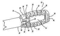
- FIG. 1is a perspective view of a minimally invasive interbody device for restoring the disc space height during spinal fusion surgery, according to an embodiment of the present invention
- FIG. 2is a top view of the interbody device shown in FIG. 1 ;
- FIG. 3is a cross-sectional, perspective view of the interbody device shown in FIG. 1 ;
- FIG. 4is a side view of the interbody device shown in FIG. 1 positioned between two vertebrae in an insertion direction;
- FIG. 5is a side view of the interbody device shown in FIG. 1 positioned between the vertebrae in a disc height restoring direction;
- FIG. 6is a perspective view of a fill tube and a minimally invasive interbody device, according to another embodiment of the present invention.
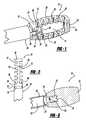
- FIG. 7is broken-away perspective view of a fill tube and a minimally invasive interbody device employing a threaded attachment, according to another embodiment of the present invention.
- FIG. 8is a broken-away perspective view of a fill tube and a minimally invasive interbody device employing a tab and slot connection, according to another embodiment of the present invention.
- FIG. 9is a broken-away perspective view of a fill tube and a minimally invasive interbody device, according to another embodiment of the present invention.
- FIG. 9Ais an end view of the fill tube shown in FIG. 9 ;
- FIG. 9Bis a broken-away end view of the interbody device shown in FIG. 9 ;
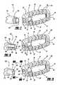
- FIG. 10is a perspective view of a minimally invasive interbody device for restoring the disc space height during spinal fusion surgery, according to another embodiment of the present invention.
- FIG. 11is a perspective view of the minimally invasive interbody device shown in FIG. 10 and including a rotating tool and a fill tube;
- FIG. 12is a perspective view of a minimally invasive interbody device for restoring the disc space height during spinal fusion surgery, according to an embodiment of the present invention.
- FIG. 1is a perspective view
- FIG. 2is a top view
- FIG. 3is a cross-sectional view of a minimally invasive interbody device 10 that is to be positioned within the interbody disc space between two vertebral bodies once the disc has been removed as part of a spinal fusion surgical procedure.
- the device 10operates to restore the disc space height that has been lost by age or damage and may be causing pain as a result of nerve pinching, as discussed above. Additionally, the device 10 facilitates the distribution of bone graft material within the disc space.
- the interbody device 10includes a perimeter portion 12 and a center plate 14 that are an integral body in this embodiment.
- the perimeter portion 12includes opposing spines 26 and 28 having ribs 30 extending therefrom.
- the ribs 30define spaces 32 between the ribs 30 along the length of the spines 26 and 28 .
- the perimeter portion 12also includes a first end piece 36 and a second end piece 38 .
- a coupling tube 18is formed to the end piece 38 where a bore 20 is defined through the coupling tube 18 and the end piece 38 .
- the center plate 14includes an opening 22 in communication with the bore 20 to facilitate the distribution of bone graft material.
- the center plate 14includes a nub 24 extending into the opening 22 , where the nub 24 helps to distribute the bone graft material on either side of the center plate 14 within the disc space.
- the center plate 14can be eliminated. However, some load bearing structure may be needed between the spines 26 and 28 .
- the body of the devicecan be a solid piece having a consistent thickness, where an opening is provided in the body to distribute the bone graft material.
- the device 10can be made of any material suitable for the purposes described herein, such as titanium or a durable plastic.
- the device 10is radiolucent and is invisible on an X-ray.
- a reflective strip 44can be attached to the end piece 36 and a reflective strip 46 can be attached to the end piece 38 .
- the reflective strips 44 and 46allow the ends of the device 10 to be visible on an X-ray so that the surgeon will know the position of the device 10 in the disc space.
- the bone graft materialis introduced through the coupling tube 18 .
- a fill tube 50is attached to the coupling tube 18 , as shown.
- the fill tube 50includes integral clasps 54 and 56 that extend from an end of the fill tube 50 , as shown.
- the clasps 54 and 56include angled end portions 58 and 60 , respectively, that allow the clasps 54 and 56 to be mounted to the interbody device 10 .
- the interbody device 10is attached to the fill tube 50 outside of the patient.
- the fill tube 50is an elongated member that extends out of the patient's body and allows the surgeon to position the interbody device 10 in the disc space, as will be discussed in more detail below.
- the clasps 54 and 56are spread apart and positioned within recesses 42 in the end piece 38 , as shown.
- the clamping force of the clasps 54 and 56allows the fill tube 50 to be securely attached to the device 10 .
- the angled end portions 58 and 60are positioned against an opposite side of the end piece 38 to help lock the fill tube 50 the coupling tube 18 .
- the clasps 54 and 56are robust enough to allow the surgeon to rotate the fill tube 50 , and cause the interbody device 10 to rotate within the disc space.
- the bone graft materialis inserted into the disc space through the coupling tube 18 and the end piece 38 .
- the bone graft materialcan be inserted into the disc space through a port outside of the device 10 , such as around the end piece 38 .
- FIG. 4shows the interbody device 10 positioned in a disc space 68 between two vertebrae 70 and 72 in an insertion direction where the wider dimension of the device 10 is parallel to the plane of vertebral bodies 74 and 76 of the vertebrae 70 and 72 , respectively.
- Bone graft materialis then introduced through the fill tube 50 into the interbody device 10 through the coupling tube 18 so that it flows into the opening 22 and is spread out on both sides of the center plate 14 .
- the bone graft materialwill enter the spaces 32 between the ribs 30 , and provide a complete and even distribution of bone graft material within the disc space 68 for proper vertebral fusion.
- the fill tube 50is pulled off of the interbody device 10 .
- the clasping strength of the clasps 54 and 56allow the interbody device 10 to be held to the fill tube 50 , but also be removed therefrom under a reasonably low enough force.
- the interbody device 10remains in the disc space 68 to maintain the disc space height and facilitate bone fusion.
- the spines 26 and 28 and the ribs 30define the width of the device 10 and the distance between the ribs 26 and 28 defines the height of the device 10 .
- the height of the interbody device 10is selected to be the desired disc height for a particular disc space so that the disc height is restored by the device 10 as part of the fusion process.
- the interbody device 10can be provided in different lengths and heights to accommodate the anatomy of different patients.
- the width of the device 10is such that it can be relatively easily slipped into the disc space 68 through a dilator tube (not shown) used in minimally invasive surgical procedures without risk of injury to the nerve roots through the same channel that the disc has been removed from.
- the device 10has a width in the range of 3-4 mm and a height in the range of 8-15 mm.
- the length of the device 10would be suitable for the size of the disc space, such as 15-25 mm.
- FIG. 6is a broken-away perspective view of a minimally invasive interbody device 80 and associated fill tube handle 82 , according to another embodiment of the present invention, where like elements to the device 10 are identified by the same reference numeral.
- the coupling tube 18is replaced with a coupling tube 84 .
- the coupling tube 84has a tapered portion 86 and a cylindrical portion 88 , both having a bore 90 running therethrough.
- Two elongated opposing tabs 92 and 94are formed to an outside surface of the cylindrical portion 88 .
- the center plate 14has been replaced with a series of support columns 96 to provide support when the interbody device 80 is rotated within the disc space.
- the support columns 96are intended to represent any suitable load bearing structure within the space defined by the perimeter portion 12
- the fill tube handle 82includes a fill tube 96 having a central bore 98 .
- a pair of slots 100 and 102is formed in the bore 98 in alignment with the elongated tabs 92 and 94 .
- the fill tube handle 82is slipped on to the coupling portion 84 so that the tabs 92 and 94 slide down the slots 100 and 102 .
- the internal bore 98then forced onto the tapered portion 86 to lock the handle 82 to the interbody device 80 .
- the coupling between the tabs 92 and 94 and the slots 100 and 102is robust enough so that the interbody device 80 can be rotated within the disc space.
- the cylindrical portion 88is positioned within the bore 98 so that minimal resistance is provided for depositing bone graft material down the bore 98 , through the coupling portion 84 and into the space between the ribs 26 and 28 .
- FIG. 7is a perspective view of a minimally invasive interbody device 110 and associated fill tube 112 , according to another embodiment of the present invention, where like elements to the interbody device 10 are identified by the same reference numeral.
- the coupling tube 18is replaced with a threaded bore 114 that extends through the end piece 38 .
- the fill tube 112includes a fill tube body 116 having a bore 118 and a threaded end portion 120 at the end of the body 116 .
- the threaded end portion 120is threaded into the threaded portion 114 in the proper direction to attach and detach the fill tube 112 to the device 110 so that the fill tube 112 can rotate the interbody device 110 .
- FIG. 8is a perspective view of a minimally invasive interbody device 130 and associated fill tube 132 , according to another embodiment of the present invention, where like elements to the interbody device 10 are identified by the same reference numeral.
- the coupling tube 18is replaced with an internal bore 134 that includes elongated tabs 136 and 138 and slots 140 and 142 .
- the fill tube 132includes a fill tube body 146 and a narrow diameter end portion 148 defining a shoulder 144 therebetween, where a central bore 150 extends through the fill tube body 146 and the end portion 148 .
- the end portion 148includes tabs 152 and 154 and slots 156 and 158 that align with the tabs 136 and 138 and the slots 140 and 142 in the bore 134 so as to allow the device 130 to be rotated by the fill tube 132 when the end portion 148 is inserted into the bore 134 .
- tabs and slotsare shown between the end portion 148 and the bore 134 , any suitable configuration of tab and slots in this manner can be used within the scope of the present invention.
- the device 130is held to the fill tube 132 by a friction engagement between the end portion 148 and the bore 134 .
- the end portion 148 and the bore 134can be tapered as a wider diameter to a narrower diameter to provide a better locking arrangement.
- the shoulder 144prevents the fill tube 132 from being pushed into the device 130 .
- FIG. 9is a perspective view of a minimally invasive interbody device 160 and associated fill tube 162 , according to another embodiment of the present invention, where like elements to the device 10 are identified by the same reference numeral.
- FIG. 9Ais an end view of the fill tube 162 and
- FIG. 9Bis a broken-away end view of the device 160 .
- the coupling tube 18is replaced with an internal bore 164 that includes a slot 166 and an arced portion 168 defining the ledge 170 .
- the fill tube 162includes a fill tube body 172 and a narrow diameter end portion 174 defining a shoulder 176 therebetween, where a central bore 178 extends through the fill tube body 162 and the end portion 174 .
- a nub 180is attached to the end of the end portion 174 and a stop 182 is attached to the end portion 174 , as shown.
- the end portion 174is inserted into the bore 164 so that the nub 180 aligns with the slot 166 .
- the end portion 174is slid into the bore 164 so that the nub 180 extends behind the end piece 38 .
- the fill tube 162is rotated so the nub 180 locks behind the end piece 38 .
- the nub 180rides up a ramp 184 so that the stop 182 is rotated and contacts the ledge 170 .
- the contact between the stop 182 and the ledge 170allows the device 160 to be rotated within the disc space, as discussed above.
- the shoulder 176 and the nub 180lock the fill tube 162 to the device 160 .
- the fill tube 162can then be rotated in the opposite direction so that the nub 180 again aligns with the slot 166 to remove the fill tube 162 , as discussed above.
- FIG. 10is a perspective view of a minimally invasive interbody device 190 for restoring the disc space height during spinal fusion surgery, according to an embodiment of the present invention, where like elements to the device 10 are identified by the same reference numeral.
- the nub 24is replaced with a triangular ridge 192 that distributes the bone graft material on both sides of the center plate 14 .
- the end piece 38is replaced with an end piece 194 .
- the end piece 194includes a cylindrical bore 196 extending therethrough.
- the end piece 194also includes a first set of two opposing slots 198 and 200 on opposite sides of the end piece 194 and a second set of two opposing slots 202 and 204 on opposite sides of the end piece 194 , as shown.
- FIG. 11is a perspective view of the interbody device 190 in combination with a rotating tool 210 and a fill tube 212 .
- the rotating tool 210includes a rectangular body 214 having a cylindrical bore 216 extending therethrough.
- the body 214includes four rigid fingers 218 that are configured to be positioned within the slots 198 - 204 , as shown, to allow the tool 210 to rotate the interbody device 190 for the purposes discussed above.
- the fill tube 212extends through the bore 216 and is coupled to or positioned relative to the ridge 190 so that bone graft material forced through the tube 212 is dispersed on both sides of the center plate 14 as discussed above.
- the end 208 of the fill tube 212may have a shape that conforms with the shape of the ridge 192 .
- FIG. 12is a perspective view of a minimally invasive interbody device 220 for restoring the disc space height during spinal fusion surgery, according to an embodiment of the present invention.
- the device 220includes opposing elongated members 222 and 224 and opposing end pieces 226 and 228 that combine to define a perimeter structure.
- a center member 230is coupled to the elongated members 222 and 224 and provides structural support.
- a rectangular opening 232is provided through the end piece 228 , and accepts a fill tube and rotating tool to rotate the interbody device 220 and provide the bone graft material within the perimeter structure, as discussed above.
Landscapes
- Health & Medical Sciences (AREA)
- Engineering & Computer Science (AREA)
- Biomedical Technology (AREA)
- Orthopedic Medicine & Surgery (AREA)
- Transplantation (AREA)
- Neurology (AREA)
- Heart & Thoracic Surgery (AREA)
- Oral & Maxillofacial Surgery (AREA)
- Cardiology (AREA)
- Vascular Medicine (AREA)
- Life Sciences & Earth Sciences (AREA)
- Animal Behavior & Ethology (AREA)
- General Health & Medical Sciences (AREA)
- Public Health (AREA)
- Veterinary Medicine (AREA)
- Physical Education & Sports Medicine (AREA)
- Prostheses (AREA)
- Surgical Instruments (AREA)
Abstract
Description
Claims (15)
Priority Applications (5)
| Application Number | Priority Date | Filing Date | Title |
|---|---|---|---|
| US11/623,356US7824427B2 (en) | 2007-01-16 | 2007-01-16 | Minimally invasive interbody device |
| US11/932,175US7846210B2 (en) | 2007-01-16 | 2007-10-31 | Minimally invasive interbody device assembly |
| PCT/US2008/051189WO2008089252A2 (en) | 2007-01-16 | 2008-01-16 | Minimally invasive interbody device assembly |
| US12/917,089US20110046743A1 (en) | 2007-01-16 | 2010-11-01 | Minimally Invasive Interbody Device |
| US12/961,121US8425612B2 (en) | 2007-01-16 | 2010-12-06 | Minimally invasive interbody device assembly |
Applications Claiming Priority (2)
| Application Number | Priority Date | Filing Date | Title |
|---|---|---|---|
| US11/623,356US7824427B2 (en) | 2007-01-16 | 2007-01-16 | Minimally invasive interbody device |
| US11/932,175US7846210B2 (en) | 2007-01-16 | 2007-10-31 | Minimally invasive interbody device assembly |
Related Child Applications (2)
| Application Number | Title | Priority Date | Filing Date |
|---|---|---|---|
| US11/932,175Continuation-In-PartUS7846210B2 (en) | 2007-01-16 | 2007-10-31 | Minimally invasive interbody device assembly |
| US12/917,089ContinuationUS20110046743A1 (en) | 2007-01-16 | 2010-11-01 | Minimally Invasive Interbody Device |
Publications (2)
| Publication Number | Publication Date |
|---|---|
| US20080172127A1 US20080172127A1 (en) | 2008-07-17 |
| US7824427B2true US7824427B2 (en) | 2010-11-02 |
Family
ID=39618382
Family Applications (4)
| Application Number | Title | Priority Date | Filing Date |
|---|---|---|---|
| US11/623,356Active2027-03-21US7824427B2 (en) | 2007-01-16 | 2007-01-16 | Minimally invasive interbody device |
| US11/932,175Expired - Fee RelatedUS7846210B2 (en) | 2007-01-16 | 2007-10-31 | Minimally invasive interbody device assembly |
| US12/917,089AbandonedUS20110046743A1 (en) | 2007-01-16 | 2010-11-01 | Minimally Invasive Interbody Device |
| US12/961,121ActiveUS8425612B2 (en) | 2007-01-16 | 2010-12-06 | Minimally invasive interbody device assembly |
Family Applications After (3)
| Application Number | Title | Priority Date | Filing Date |
|---|---|---|---|
| US11/932,175Expired - Fee RelatedUS7846210B2 (en) | 2007-01-16 | 2007-10-31 | Minimally invasive interbody device assembly |
| US12/917,089AbandonedUS20110046743A1 (en) | 2007-01-16 | 2010-11-01 | Minimally Invasive Interbody Device |
| US12/961,121ActiveUS8425612B2 (en) | 2007-01-16 | 2010-12-06 | Minimally invasive interbody device assembly |
Country Status (2)
| Country | Link |
|---|---|
| US (4) | US7824427B2 (en) |
| WO (1) | WO2008089252A2 (en) |
Cited By (34)
| Publication number | Priority date | Publication date | Assignee | Title |
|---|---|---|---|---|
| US20110029081A1 (en)* | 2000-12-14 | 2011-02-03 | Depuy Spine, Inc. | Devices and methods for facilitating controlled bone growth or repair |
| US20110046736A1 (en)* | 2008-01-15 | 2011-02-24 | Henry Graf | Intervertebral stabilization assembly for arthrodesis, comprising an impaction cage body, and an ancillary device for implanting same |
| US8142441B2 (en)* | 2008-10-16 | 2012-03-27 | Aesculap Implant Systems, Llc | Surgical instrument and method of use for inserting an implant between two bones |
| US8623088B1 (en) | 2005-07-15 | 2014-01-07 | Nuvasive, Inc. | Spinal fusion implant and related methods |
| US8795368B2 (en) | 2011-04-27 | 2014-08-05 | Warsaw Orthopedic, Inc. | Expandable implant system and methods of use |
| US9034046B2 (en) | 2007-10-30 | 2015-05-19 | Aesculap Implant Systems, Llc | Vertebral body replacement device and method for use to maintain a space between two vertebral bodies within a spine |
| USD731063S1 (en) | 2009-10-13 | 2015-06-02 | Nuvasive, Inc. | Spinal fusion implant |
| US9132021B2 (en) | 2011-10-07 | 2015-09-15 | Pioneer Surgical Technology, Inc. | Intervertebral implant |
| USD741488S1 (en) | 2006-07-17 | 2015-10-20 | Nuvasive, Inc. | Spinal fusion implant |
| US9216096B2 (en) | 2010-03-16 | 2015-12-22 | Pinnacle Spine Group, Llc | Intervertebral implants and related tools |
| US9308099B2 (en) | 2011-02-14 | 2016-04-12 | Imds Llc | Expandable intervertebral implants and instruments |
| US9380932B1 (en) | 2011-11-02 | 2016-07-05 | Pinnacle Spine Group, Llc | Retractor devices for minimally invasive access to the spine |
| US20180049754A1 (en)* | 2015-03-13 | 2018-02-22 | Redemed S.R.L. | Intervertebral prosthesis, apparatus for implanting intervertebral prostheses and surgical method for implanting intervertebral prostheses, particularly for percutaneous mini-invasive surgery procedures |
| US10070970B2 (en) | 2013-03-14 | 2018-09-11 | Pinnacle Spine Group, Llc | Interbody implants and graft delivery systems |
| US10105238B2 (en) | 2015-08-25 | 2018-10-23 | Imds Llc | Expandable intervertebral implants |
| USD907771S1 (en) | 2017-10-09 | 2021-01-12 | Pioneer Surgical Technology, Inc. | Intervertebral implant |
| US10932918B2 (en) | 2014-03-04 | 2021-03-02 | DePuy Synthes Products, Inc. | Post-operative bone growth stimulant introduction method |
| US10945859B2 (en) | 2018-01-29 | 2021-03-16 | Amplify Surgical, Inc. | Expanding fusion cages |
| US10993815B2 (en) | 2016-10-25 | 2021-05-04 | Imds Llc | Methods and instrumentation for intervertebral cage expansion |
| US11033403B2 (en) | 2017-07-10 | 2021-06-15 | Life Spine, Inc. | Expandable implant assembly |
| US20210236167A1 (en)* | 2020-01-31 | 2021-08-05 | Artoss, Inc. | Delivery device for biologic material |
| US11103362B2 (en)* | 2013-03-13 | 2021-08-31 | Life Spine, Inc. | Expandable implant assembly |
| US11147682B2 (en) | 2017-09-08 | 2021-10-19 | Pioneer Surgical Technology, Inc. | Intervertebral implants, instruments, and methods |
| US11304818B2 (en) | 2013-03-13 | 2022-04-19 | Life Spine, Inc. | Expandable spinal interbody assembly |
| US11382764B2 (en) | 2019-06-10 | 2022-07-12 | Life Spine, Inc. | Expandable implant assembly with compression features |
| US20220304824A1 (en)* | 2019-03-07 | 2022-09-29 | Spinal Surgical Strategies, Inc., A Nevada Corporation D/B/A Kleiner Device Labs | Bone graft delivery system and method for using same |
| US11602439B2 (en) | 2020-04-16 | 2023-03-14 | Life Spine, Inc. | Expandable implant assembly |
| US11602440B2 (en) | 2020-06-25 | 2023-03-14 | Life Spine, Inc. | Expandable implant assembly |
| US11857432B2 (en) | 2020-04-13 | 2024-01-02 | Life Spine, Inc. | Expandable implant assembly |
| US11896494B2 (en) | 2017-07-10 | 2024-02-13 | Life Spine, Inc. | Expandable implant assembly |
| US12042395B2 (en) | 2019-06-11 | 2024-07-23 | Life Spine, Inc. | Expandable implant assembly |
| US12193948B2 (en) | 2013-03-13 | 2025-01-14 | Life Spine, Inc. | Expandable implant assembly |
| US12336917B2 (en) | 2020-05-15 | 2025-06-24 | Life Spine, Inc. | Steerable implant assembly |
| US12364610B2 (en) | 2020-09-08 | 2025-07-22 | Life Spine, Inc. | Expandable implant with pivoting control assembly |
Families Citing this family (113)
| Publication number | Priority date | Publication date | Assignee | Title |
|---|---|---|---|---|
| US7918891B1 (en)* | 2004-03-29 | 2011-04-05 | Nuvasive Inc. | Systems and methods for spinal fusion |
| WO2008070863A2 (en) | 2006-12-07 | 2008-06-12 | Interventional Spine, Inc. | Intervertebral implant |
| US9039768B2 (en) | 2006-12-22 | 2015-05-26 | Medos International Sarl | Composite vertebral spacers and instrument |
| US8673005B1 (en) | 2007-03-07 | 2014-03-18 | Nuvasive, Inc. | System and methods for spinal fusion |
| US8123811B2 (en)* | 2007-04-27 | 2012-02-28 | Atlas Spine, Inc. | Cervical implant |
| US8900307B2 (en) | 2007-06-26 | 2014-12-02 | DePuy Synthes Products, LLC | Highly lordosed fusion cage |
| US8888850B2 (en)* | 2007-11-19 | 2014-11-18 | Linares Medical Devices, Llc | Combination spacer insert and support for providing inter-cervical vertebral support |
| EP2237748B1 (en) | 2008-01-17 | 2012-09-05 | Synthes GmbH | An expandable intervertebral implant |
| US8088163B1 (en) | 2008-02-06 | 2012-01-03 | Kleiner Jeffrey B | Tools and methods for spinal fusion |
| US8083796B1 (en) | 2008-02-29 | 2011-12-27 | Nuvasive, Inc. | Implants and methods for spinal fusion |
| US20090248092A1 (en) | 2008-03-26 | 2009-10-01 | Jonathan Bellas | Posterior Intervertebral Disc Inserter and Expansion Techniques |
| US8936641B2 (en) | 2008-04-05 | 2015-01-20 | DePuy Synthes Products, LLC | Expandable intervertebral implant |
| US20210378834A1 (en) | 2008-05-22 | 2021-12-09 | Spinal Surgical Strategies, Inc., A Nevada Corporation D/B/A Kleiner Device Labs | Spinal fusion cage system with inserter |
| EP2303196B1 (en)* | 2008-07-23 | 2018-10-24 | Marc I. Malberg | Modular nucleus pulposus prosthesis |
| USD853560S1 (en) | 2008-10-09 | 2019-07-09 | Nuvasive, Inc. | Spinal implant insertion device |
| US8545566B2 (en)* | 2008-10-13 | 2013-10-01 | Globus Medical, Inc. | Articulating spacer |
| US8147554B2 (en)* | 2008-10-13 | 2012-04-03 | Globus Medical, Inc. | Intervertebral spacer |
| US8366748B2 (en) | 2008-12-05 | 2013-02-05 | Kleiner Jeffrey | Apparatus and method of spinal implant and fusion |
| US9247943B1 (en) | 2009-02-06 | 2016-02-02 | Kleiner Intellectual Property, Llc | Devices and methods for preparing an intervertebral workspace |
| USD656610S1 (en) | 2009-02-06 | 2012-03-27 | Kleiner Jeffrey B | Spinal distraction instrument |
| USD754346S1 (en) | 2009-03-02 | 2016-04-19 | Nuvasive, Inc. | Spinal fusion implant |
| US9526620B2 (en) | 2009-03-30 | 2016-12-27 | DePuy Synthes Products, Inc. | Zero profile spinal fusion cage |
| US8906028B2 (en) | 2009-09-18 | 2014-12-09 | Spinal Surgical Strategies, Llc | Bone graft delivery device and method of using the same |
| USD723682S1 (en) | 2013-05-03 | 2015-03-03 | Spinal Surgical Strategies, Llc | Bone graft delivery tool |
| US20170238984A1 (en) | 2009-09-18 | 2017-08-24 | Spinal Surgical Strategies, Llc | Bone graft delivery device with positioning handle |
| USD750249S1 (en) | 2014-10-20 | 2016-02-23 | Spinal Surgical Strategies, Llc | Expandable fusion cage |
| US9060877B2 (en) | 2009-09-18 | 2015-06-23 | Spinal Surgical Strategies, Llc | Fusion cage with combined biological delivery system |
| US9173694B2 (en) | 2009-09-18 | 2015-11-03 | Spinal Surgical Strategies, Llc | Fusion cage with combined biological delivery system |
| US9629729B2 (en)* | 2009-09-18 | 2017-04-25 | Spinal Surgical Strategies, Llc | Biological delivery system with adaptable fusion cage interface |
| US8685031B2 (en)* | 2009-09-18 | 2014-04-01 | Spinal Surgical Strategies, Llc | Bone graft delivery system |
| US10245159B1 (en) | 2009-09-18 | 2019-04-02 | Spinal Surgical Strategies, Llc | Bone graft delivery system and method for using same |
| US10973656B2 (en) | 2009-09-18 | 2021-04-13 | Spinal Surgical Strategies, Inc. | Bone graft delivery system and method for using same |
| US9186193B2 (en) | 2009-09-18 | 2015-11-17 | Spinal Surgical Strategies, Llc | Fusion cage with combined biological delivery system |
| US9028553B2 (en) | 2009-11-05 | 2015-05-12 | DePuy Synthes Products, Inc. | Self-pivoting spinal implant and associated instrumentation |
| US9168138B2 (en) | 2009-12-09 | 2015-10-27 | DePuy Synthes Products, Inc. | Aspirating implants and method of bony regeneration |
| US9393129B2 (en) | 2009-12-10 | 2016-07-19 | DePuy Synthes Products, Inc. | Bellows-like expandable interbody fusion cage |
| US8945227B2 (en)* | 2010-02-01 | 2015-02-03 | X-Spine Systems, Inc. | Spinal implant co-insertion system and method |
| US9301853B2 (en)* | 2010-04-09 | 2016-04-05 | DePuy Synthes Products, Inc. | Holder for implantation and extraction of prosthesis |
| US9907560B2 (en) | 2010-06-24 | 2018-03-06 | DePuy Synthes Products, Inc. | Flexible vertebral body shavers |
| US8979860B2 (en) | 2010-06-24 | 2015-03-17 | DePuy Synthes Products. LLC | Enhanced cage insertion device |
| US8623091B2 (en) | 2010-06-29 | 2014-01-07 | DePuy Synthes Products, LLC | Distractible intervertebral implant |
| CN103096843A (en) | 2010-07-21 | 2013-05-08 | Nlt脊椎有限公司 | Spinal surgery implants and delivery system |
| US9066814B2 (en) | 2010-08-02 | 2015-06-30 | Ulrich Medical Usa, Inc. | Implant assembly having an angled head |
| US20120071981A1 (en)* | 2010-08-27 | 2012-03-22 | Farley Daniel K | Methods and Systems for Interbody Implant and Bone Graft Delivery |
| US9480576B2 (en)* | 2010-08-27 | 2016-11-01 | Thompson Mis | Methods and systems for interbody implant and bone graft delivery |
| US8852282B2 (en)* | 2010-08-27 | 2014-10-07 | Daniel K. Farley | Methods and systems for interbody implant and bone graft delivery |
| US20120065613A1 (en)* | 2010-08-27 | 2012-03-15 | Pepper John R | Methods and Systems for Interbody Implant and Bone Graft Delivery |
| AU2011305680B2 (en) | 2010-09-20 | 2014-09-11 | Jeffrey Kleiner | Fusion cage with combined biological delivery system |
| US20120078372A1 (en) | 2010-09-23 | 2012-03-29 | Thomas Gamache | Novel implant inserter having a laterally-extending dovetail engagement feature |
| US11529241B2 (en) | 2010-09-23 | 2022-12-20 | DePuy Synthes Products, Inc. | Fusion cage with in-line single piece fixation |
| US20120078373A1 (en) | 2010-09-23 | 2012-03-29 | Thomas Gamache | Stand alone intervertebral fusion device |
| US9044284B2 (en)* | 2010-09-29 | 2015-06-02 | Spinal Generations, Llc | Intervertebral insert system |
| US8858637B2 (en)* | 2010-09-30 | 2014-10-14 | Stryker Spine | Surgical implant with guiding rail |
| US9402732B2 (en) | 2010-10-11 | 2016-08-02 | DePuy Synthes Products, Inc. | Expandable interspinous process spacer implant |
| EP3485851B1 (en) | 2011-03-22 | 2021-08-25 | DePuy Synthes Products, LLC | Universal trial for lateral cages |
| EP2535021B1 (en)* | 2011-06-14 | 2015-10-14 | Biedermann Technologies GmbH & Co. KG | Intervertebral implant |
| US9248028B2 (en) | 2011-09-16 | 2016-02-02 | DePuy Synthes Products, Inc. | Removable, bone-securing cover plate for intervertebral fusion cage |
| US9198765B1 (en) | 2011-10-31 | 2015-12-01 | Nuvasive, Inc. | Expandable spinal fusion implants and related methods |
| US20130178940A1 (en)* | 2012-01-06 | 2013-07-11 | Thompson Mis | Expandable cage spinal implant |
| US9034043B2 (en)* | 2012-02-03 | 2015-05-19 | Zimmer Spine, Inc. | Intervertebral implant and insertion instrument |
| US9060870B2 (en) | 2012-02-05 | 2015-06-23 | Michael J. Milella, Jr. | In-situ formed spinal implant |
| US9271836B2 (en) | 2012-03-06 | 2016-03-01 | DePuy Synthes Products, Inc. | Nubbed plate |
| US10182921B2 (en) | 2012-11-09 | 2019-01-22 | DePuy Synthes Products, Inc. | Interbody device with opening to allow packing graft and other biologics |
| US8715351B1 (en) | 2012-11-29 | 2014-05-06 | Spine Wave, Inc. | Expandable interbody fusion device with graft chambers |
| US8663332B1 (en) | 2012-12-13 | 2014-03-04 | Ouroboros Medical, Inc. | Bone graft distribution system |
| US10022245B2 (en) | 2012-12-17 | 2018-07-17 | DePuy Synthes Products, Inc. | Polyaxial articulating instrument |
| US9572684B2 (en)* | 2012-12-26 | 2017-02-21 | Innovasis, Inc. | Interbody insertion tool and method |
| US9717601B2 (en) | 2013-02-28 | 2017-08-01 | DePuy Synthes Products, Inc. | Expandable intervertebral implant, system, kit and method |
| US9522070B2 (en) | 2013-03-07 | 2016-12-20 | Interventional Spine, Inc. | Intervertebral implant |
| US8900312B2 (en) | 2013-03-12 | 2014-12-02 | Spine Wave, Inc. | Expandable interbody fusion device with graft chambers |
| US8828019B1 (en) | 2013-03-13 | 2014-09-09 | Spine Wave, Inc. | Inserter for expanding an expandable interbody fusion device |
| US10327910B2 (en) | 2013-03-14 | 2019-06-25 | X-Spine Systems, Inc. | Spinal implant and assembly |
| US9186259B2 (en) | 2013-09-09 | 2015-11-17 | Ouroboros Medical, Inc. | Expandable trials |
| US9445921B2 (en) | 2014-03-06 | 2016-09-20 | Spine Wave, Inc. | Device for expanding and supporting body tissue |
| US9439783B2 (en) | 2014-03-06 | 2016-09-13 | Spine Wave, Inc. | Inserter for expanding body tissue |
| US11065132B2 (en) | 2014-03-06 | 2021-07-20 | Spine Wave, Inc. | Method of expanding a space between opposing tissue surfaces |
| US9107766B1 (en) | 2014-03-06 | 2015-08-18 | Spine Wave, Inc. | Expandable spinal interbody fusion device and inserter |
| US9265623B2 (en) | 2014-03-06 | 2016-02-23 | Spine Wave, Inc. | Method of expanding a spinal interbody fusion device |
| US9427328B2 (en)* | 2014-03-10 | 2016-08-30 | Warsaw Orthopedic, Inc. | Interbody implant system and method |
| US10238507B2 (en)* | 2015-01-12 | 2019-03-26 | Surgentec, Llc | Bone graft delivery system and method for using same |
| US9060876B1 (en) | 2015-01-20 | 2015-06-23 | Ouroboros Medical, Inc. | Stabilized intervertebral scaffolding systems |
| US11426290B2 (en) | 2015-03-06 | 2022-08-30 | DePuy Synthes Products, Inc. | Expandable intervertebral implant, system, kit and method |
| US10952866B2 (en) | 2015-10-13 | 2021-03-23 | DePuy Synthes Products, Inc. | Intervertebral implant and bone graft inserter |
| USD797290S1 (en) | 2015-10-19 | 2017-09-12 | Spinal Surgical Strategies, Llc | Bone graft delivery tool |
| US10492925B2 (en) | 2016-03-03 | 2019-12-03 | Spine Wave, Inc. | Graft delivery system |
| US10285825B2 (en)* | 2016-04-07 | 2019-05-14 | Howmedica Osteonics Corp. | Surgical insertion instruments |
| US10433981B2 (en) | 2016-05-13 | 2019-10-08 | Spine Wave, Inc. | Graft delivery apparatus |
| EP3474784A2 (en) | 2016-06-28 | 2019-05-01 | Eit Emerging Implant Technologies GmbH | Expandable and angularly adjustable intervertebral cages with articulating joint |
| US11510788B2 (en) | 2016-06-28 | 2022-11-29 | Eit Emerging Implant Technologies Gmbh | Expandable, angularly adjustable intervertebral cages |
| US9883953B1 (en) | 2016-09-21 | 2018-02-06 | Integrity Implants Inc. | Stabilized laterovertically-expanding fusion cage systems with tensioner |
| US10231849B2 (en) | 2016-10-13 | 2019-03-19 | Warsaw Orthopedic, Inc. | Surgical instrument system and method |
| JP7085554B2 (en) | 2017-01-10 | 2022-06-16 | インテグリティ インプランツ インコーポレイテッド | Deployable intervertebral fusion device |
| EP3357459A1 (en)* | 2017-02-03 | 2018-08-08 | Spinal Surgical Strategies, LLC | Bone graft delivery device with positioning handle |
| US10398563B2 (en) | 2017-05-08 | 2019-09-03 | Medos International Sarl | Expandable cage |
| US10940016B2 (en) | 2017-07-05 | 2021-03-09 | Medos International Sarl | Expandable intervertebral fusion cage |
| US10966843B2 (en) | 2017-07-18 | 2021-04-06 | DePuy Synthes Products, Inc. | Implant inserters and related methods |
| CN111031969A (en) | 2017-07-24 | 2020-04-17 | 整体植入有限公司 | Surgical implants and related methods |
| US11045331B2 (en) | 2017-08-14 | 2021-06-29 | DePuy Synthes Products, Inc. | Intervertebral implant inserters and related methods |
| US10709578B2 (en) | 2017-08-25 | 2020-07-14 | Integrity Implants Inc. | Surgical biologics delivery system and related methods |
| EP3456297B1 (en) | 2017-09-15 | 2023-10-04 | Howmedica Osteonics Corp. | Instruments for expandable interbody implants |
| FR3075032A1 (en)* | 2017-12-18 | 2019-06-21 | Bpath | DEVICE FOR DISTRACTING AND INTERSOMATIC STABILIZATION |
| JP7572857B2 (en) | 2018-03-01 | 2024-10-24 | インテグリティ インプランツ インコーポレイテッド | Expandable Fusion Device with Independent Deployment System |
| US11446156B2 (en) | 2018-10-25 | 2022-09-20 | Medos International Sarl | Expandable intervertebral implant, inserter instrument, and related methods |
| US11793558B2 (en) | 2019-08-30 | 2023-10-24 | K2M, Inc. | All in one plate holder and spring loaded awl |
| US11426286B2 (en) | 2020-03-06 | 2022-08-30 | Eit Emerging Implant Technologies Gmbh | Expandable intervertebral implant |
| EP4171448A4 (en) | 2020-07-20 | 2025-02-12 | Integrity Implants Inc. | EXPANDABLE FUSION DEVICE WITH INDEPENDENT EXPANSION SYSTEMS |
| CN112274321B (en)* | 2020-10-28 | 2023-04-07 | 四川大学华西医院 | Artificial auditory ossicle operation mounting forceps |
| CN112137776B (en)* | 2020-11-26 | 2021-03-19 | 珠海维尔康生物科技有限公司 | Fusion cage implantation holder |
| US20240050237A1 (en)* | 2020-12-16 | 2024-02-15 | K2M, Inc. | Augmentable Expanding Implant |
| US11850160B2 (en) | 2021-03-26 | 2023-12-26 | Medos International Sarl | Expandable lordotic intervertebral fusion cage |
| US11752009B2 (en) | 2021-04-06 | 2023-09-12 | Medos International Sarl | Expandable intervertebral fusion cage |
| US20240148516A1 (en)* | 2021-07-09 | 2024-05-09 | University Of Florida Research Foundation, Inc. | Method, apparatus, and system for facet fusion |
| US12090064B2 (en) | 2022-03-01 | 2024-09-17 | Medos International Sarl | Stabilization members for expandable intervertebral implants, and related systems and methods |
Citations (103)
| Publication number | Priority date | Publication date | Assignee | Title |
|---|---|---|---|---|
| US4232670A (en) | 1978-06-30 | 1980-11-11 | Howmedica International, Inc. Zweigniederlassung | Tube type supply container for medical syringe |
| US4625722A (en) | 1985-05-03 | 1986-12-02 | Murray William M | Bone cement system and method |
| US4735346A (en) | 1985-08-29 | 1988-04-05 | Stoody William R | Child resistant valving nozzle |
| US4834757A (en) | 1987-01-22 | 1989-05-30 | Brantigan John W | Prosthetic implant |
| JPH0391694A (en) | 1989-09-01 | 1991-04-17 | Shinwa Sangyo Kk | Indirect heat exchanging device |
| US5159732A (en) | 1989-02-23 | 1992-11-03 | Bsrd Limited | Seat belt buckle |
| US5425772A (en)* | 1993-09-20 | 1995-06-20 | Brantigan; John W. | Prosthetic implant for intervertebral spinal fusion |
| US5443514A (en) | 1993-10-01 | 1995-08-22 | Acromed Corporation | Method for using spinal implants |
| US5458638A (en) | 1989-07-06 | 1995-10-17 | Spine-Tech, Inc. | Non-threaded spinal implant |
| US5549679A (en)* | 1994-05-20 | 1996-08-27 | Kuslich; Stephen D. | Expandable fabric implant for stabilizing the spinal motion segment |
| US5569262A (en) | 1995-05-19 | 1996-10-29 | Carney; William P. | Guide tool for surgical devices |
| US5607424A (en)* | 1995-04-10 | 1997-03-04 | Tropiano; Patrick | Domed cage |
| WO1997030666A2 (en) | 1996-02-22 | 1997-08-28 | Sdgi Holdings, Inc. | Methods and instruments for interbody fusion |
| US5683463A (en)* | 1993-08-06 | 1997-11-04 | Advanced Technical Fabrication | Intersomatic vertebral column implant |
| US5716415A (en) | 1993-10-01 | 1998-02-10 | Acromed Corporation | Spinal implant |
| US5788702A (en) | 1992-06-15 | 1998-08-04 | Draenert; Klaus | Applicator system |
| US5885292A (en) | 1996-06-25 | 1999-03-23 | Sdgi Holdings, Inc. | Minimally invasive spinal surgical methods and instruments |
| US5888228A (en)* | 1995-10-20 | 1999-03-30 | Synthes (U.S.A.) | Intervertebral implant with cage and rotating element |
| US5893890A (en) | 1994-03-18 | 1999-04-13 | Perumala Corporation | Rotating, locking intervertebral disk stabilizer and applicator |
| US5954728A (en) | 1997-04-16 | 1999-09-21 | Sulzer Orthopaedie Ag | Filling apparatus for bone cement |
| US5980522A (en)* | 1994-07-22 | 1999-11-09 | Koros; Tibor | Expandable spinal implants |
| US6004326A (en) | 1997-09-10 | 1999-12-21 | United States Surgical | Method and instrumentation for implant insertion |
| US6019765A (en) | 1998-05-06 | 2000-02-01 | Johnson & Johnson Professional, Inc. | Morsellized bone allograft applicator device |
| US6059829A (en) | 1995-03-08 | 2000-05-09 | Synthese | Intervertebral implant |
| US6066175A (en) | 1993-02-16 | 2000-05-23 | Henderson; Fraser C. | Fusion stabilization chamber |
| US6066174A (en) | 1995-10-16 | 2000-05-23 | Sdgi Holdings, Inc. | Implant insertion device |
| US6080158A (en) | 1999-08-23 | 2000-06-27 | Lin; Chih-I | Intervertebral fusion device |
| US6245108B1 (en) | 1999-02-25 | 2001-06-12 | Spineco | Spinal fusion implant |
| US20010010021A1 (en)* | 1999-01-08 | 2001-07-26 | Boyd Lawrence M. | Flexible implant using partially demineralized bone |
| US6290724B1 (en) | 1998-05-27 | 2001-09-18 | Nuvasive, Inc. | Methods for separating and stabilizing adjacent vertebrae |
| US6309421B1 (en) | 1994-03-18 | 2001-10-30 | Madhavan Pisharodi | Rotating, locking intervertebral disk stabilizer and applicator |
| US6375655B1 (en) | 1995-03-27 | 2002-04-23 | Sdgi Holdings, Inc. | Interbody fusion device and method for restoration of normal spinal anatomy |
| US6413278B1 (en) | 1998-03-30 | 2002-07-02 | J. Alexander Marchosky | Prosthetic system |
| US6425920B1 (en) | 1999-10-13 | 2002-07-30 | James S. Hamada | Spinal fusion implant |
| US20020143401A1 (en) | 2001-03-27 | 2002-10-03 | Michelson Gary K. | Radially expanding interbody spinal fusion implants, instrumentation, and methods of insertion |
| US6471724B2 (en) | 1995-03-27 | 2002-10-29 | Sdgi Holdings, Inc. | Methods and instruments for interbody fusion |
| US20020177897A1 (en) | 2001-02-04 | 2002-11-28 | Michelson Gary K. | Instrumentation and method for inserting and deploying and expandable interbody spinal fusion implant |
| US6558424B2 (en)* | 2001-06-28 | 2003-05-06 | Depuy Acromed | Modular anatomic fusion device |
| US6610065B1 (en) | 1998-10-28 | 2003-08-26 | Sdgi Holdings, Inc. | Interbody fusion implants and instrumentation |
| US20040030387A1 (en)* | 2002-03-11 | 2004-02-12 | Landry Michael E. | Instrumentation and procedure for implanting spinal implant devices |
| US20040034430A1 (en)* | 2002-06-14 | 2004-02-19 | Falahee Mark H. | Anatomic vertebral cage |
| US6709458B2 (en) | 2000-02-04 | 2004-03-23 | Gary Karlin Michelson | Expandable push-in arcuate interbody spinal fusion implant with tapered configuration during insertion |
| US6716245B2 (en)* | 2000-07-12 | 2004-04-06 | Spine Next | Intersomatic implant |
| US6746454B2 (en) | 2000-11-07 | 2004-06-08 | Osteotech, Inc. | Implant insertion tool |
| US6746484B1 (en) | 1997-08-26 | 2004-06-08 | Society De Fabrication De Materiel De Orthopedique, S.A. | Spinal implant |
| US6749595B1 (en) | 2000-06-15 | 2004-06-15 | Kieran P. J. Murphy | Cement delivery needle |
| US20040122518A1 (en) | 2002-12-19 | 2004-06-24 | Rhoda William S. | Intervertebral implant |
| US20040127993A1 (en) | 2002-10-16 | 2004-07-01 | Erich Kast | Spreader implant for placement between vertebrae |
| US20040133280A1 (en)* | 2002-11-21 | 2004-07-08 | Trieu Hai H. | Systems and techniques for interbody spinal stabilization with expandable devices |
| US20040176853A1 (en) | 2003-03-05 | 2004-09-09 | Sennett Andrew R. | Apparatus and method for spinal fusion using posteriorly implanted devices |
| US6827740B1 (en) | 1999-12-08 | 2004-12-07 | Gary K. Michelson | Spinal implant surface configuration |
| US20050049704A1 (en)* | 2003-08-29 | 2005-03-03 | Jackson Roger P. | Convex spinal fusion interbody spacer |
| US20050070900A1 (en) | 2003-09-30 | 2005-03-31 | Depuy Acromed, Inc. | Vertebral fusion device and method for using same |
| US6887248B2 (en) | 1998-05-27 | 2005-05-03 | Nuvasive, Inc. | Bone blocks and methods for inserting bone blocks into intervertebral spaces |
| US20050119747A1 (en)* | 2002-02-26 | 2005-06-02 | Sdgi Holdings, Inc. | Connectable interbody implant |
| US6942698B1 (en) | 2004-04-23 | 2005-09-13 | Roger P. Jackson | Spinal fusion interbody spacer |
| US6976949B2 (en) | 2002-10-11 | 2005-12-20 | Proxima Therapeutics, Inc. | Treatment of spinal metastases |
| US7018416B2 (en) | 2000-07-06 | 2006-03-28 | Zimmer Spine, Inc. | Bone implants and methods |
| US7025771B2 (en) | 2000-06-30 | 2006-04-11 | Spineology, Inc. | Tool to direct bone replacement material |
| US7048743B2 (en) | 1999-09-30 | 2006-05-23 | Arthrocare Corporation | Methods for delivering tissue implant material with a high pressure applicator |
| US20060149279A1 (en) | 2001-07-30 | 2006-07-06 | Mathews Hallett H | Methods and devices for interbody spinal stabilization |
| US20060167547A1 (en)* | 2005-01-21 | 2006-07-27 | Loubert Suddaby | Expandable intervertebral fusion implants having hinged sidewalls |
| US20060224241A1 (en)* | 2005-03-31 | 2006-10-05 | Life Spine, Llc | Expandable spinal interbody and intravertebral body devices |
| US7125425B2 (en) | 2002-10-21 | 2006-10-24 | Sdgi Holdings, Inc. | Systems and techniques for restoring and maintaining intervertebral anatomy |
| US20060247771A1 (en)* | 2005-04-29 | 2006-11-02 | Peterman Marc M | Expandable spinal implant and associated instrumentation |
| US7156877B2 (en)* | 2001-06-29 | 2007-01-02 | The Regents Of The University Of California | Biodegradable/bioactive nucleus pulposus implant and method for treating degenerated intervertebral discs |
| US7169183B2 (en) | 2000-03-14 | 2007-01-30 | Warsaw Orthopedic, Inc. | Vertebral implant for promoting arthrodesis of the spine |
| JP2007075632A (en) | 1996-02-19 | 2007-03-29 | Warsaw Orthopaedic Inc | Spinal fusion implant, and tool for insertion and revision |
| US20070093897A1 (en)* | 2005-10-21 | 2007-04-26 | Stryker Spine (In France) | System and method for fusion cage implantation |
| US7217293B2 (en) | 2003-11-21 | 2007-05-15 | Warsaw Orthopedic, Inc. | Expandable spinal implant |
| US7220280B2 (en) | 2002-10-16 | 2007-05-22 | Advanced Medical Technologies Ag | Spreader implant for placement between vertebrae |
| US7232463B2 (en) | 2002-10-23 | 2007-06-19 | U.S. Spinal Technologies, Llc | Intervertebral cage designs |
| US20070162132A1 (en) | 2005-12-23 | 2007-07-12 | Dominique Messerli | Flexible elongated chain implant and method of supporting body tissue with same |
| US20070173938A1 (en)* | 2006-01-26 | 2007-07-26 | Spinal Generations, Llc | Interbody cage system |
| US20070233146A1 (en)* | 2006-01-27 | 2007-10-04 | Stryker Corporation | Low pressure delivery system and method for delivering a solid and liquid mixture into a target site for medical treatment |
| US20070260320A1 (en) | 2005-03-28 | 2007-11-08 | Peterman Marc M | Spinal system and method including lateral approach |
| US20070276406A1 (en) | 2004-02-09 | 2007-11-29 | Depuy Spine, Inc | Systems and Methods for Spinal Surgery |
| US20070282441A1 (en) | 2006-05-19 | 2007-12-06 | Katie Stream | Spinal Stabilization Device and Methods |
| US7306611B2 (en) | 2001-09-19 | 2007-12-11 | Bio Holdings International Limited | Device for delivering a biomaterial |
| US20070293949A1 (en) | 2004-10-08 | 2007-12-20 | Salerni Anthony A | Interior connecting interbody cage insertional tools, methods and devices |
| US20080009880A1 (en) | 2006-03-22 | 2008-01-10 | Warnick David R | Pivotable Vetrebral Spacer |
| US20080015701A1 (en) | 2001-11-09 | 2008-01-17 | Javier Garcia | Spinal implant |
| US7331996B2 (en) | 2002-08-20 | 2008-02-19 | Showa Ika Kohgyo Co., Ltd. | Intervertebral spacer |
| US7341600B2 (en)* | 2002-12-17 | 2008-03-11 | Co-Ligne Ag | Cylindrical fiber reinforced implant |
| US20080071372A1 (en) | 2006-09-14 | 2008-03-20 | Butler Michael S | Cervical and lumbar spinal interbody devices |
| US20080091211A1 (en) | 2006-10-11 | 2008-04-17 | G & L Consulting | Spine implant insertion device and method |
| US7371241B2 (en) | 2001-02-12 | 2008-05-13 | Modmed Therapeutics, Inc. | Multi-use surgical cement dispenser apparatus and kit for same |
| US20080269901A1 (en) | 2007-04-27 | 2008-10-30 | Baynham Bret O | Spinal implant |
| US20080269756A1 (en) | 2007-04-27 | 2008-10-30 | Spinemedica, Inc. | Surgical instruments for spinal disc implants and related methods |
| US20080288076A1 (en) | 2006-09-27 | 2008-11-20 | Teck Soo | Spinal interbody spacer |
| US20080306598A1 (en) | 2007-04-02 | 2008-12-11 | Eric Hansen | Spinal implant with biologic sponge |
| US7473256B2 (en) | 2003-10-23 | 2009-01-06 | Trans1 Inc. | Method and apparatus for spinal distraction |
| US20090043394A1 (en) | 1995-03-27 | 2009-02-12 | Thomas Zdeblick | Spinal fusion implants and tools for insertion and revision |
| US20090177195A1 (en) | 2008-01-07 | 2009-07-09 | Spinal Kinetics, Inc. | Alignable Tools for Preparing an Intervertebral Site for Implanting a Prosthetic Intervertebral Disc and a Method for Using Those Tools |
| US7569074B2 (en) | 2003-12-11 | 2009-08-04 | Warsaw Orthopedic, Inc. | Expandable intervertebral implant |
| US7572263B2 (en) | 1998-04-01 | 2009-08-11 | Arthrocare Corporation | High pressure applicator |
| US20090204214A1 (en) | 2008-02-07 | 2009-08-13 | Showa Ika Kohgyo Co., Ltd. | Cage |
| US20090228110A1 (en) | 2008-03-07 | 2009-09-10 | K2M, Inc. | Intervertebral instrument, implant, and method |
| US20090248163A1 (en) | 2008-03-31 | 2009-10-01 | King Emily E | Spinal surgery interbody |
| US20100004747A1 (en) | 2008-07-07 | 2010-01-07 | Jin-Fu Lin | Trans-Vertebral and Intra-Vertebral Plate and Fusion Cage Device for Spinal Interbody Fusion and Method of Operation |
| US20100016972A1 (en) | 2008-07-17 | 2010-01-21 | Spinalmotion, Inc. | Artificial Intervertebral Disc Placement System |
| US20100023128A1 (en) | 2008-07-23 | 2010-01-28 | Malberg Marc I | Modular nucleus pulposus prosthesis |
| US20100042218A1 (en) | 2008-08-13 | 2010-02-18 | Nebosky Paul S | Orthopaedic implant with porous structural member |
Family Cites Families (5)
| Publication number | Priority date | Publication date | Assignee | Title |
|---|---|---|---|---|
| US6245072B1 (en)* | 1995-03-27 | 2001-06-12 | Sdgi Holdings, Inc. | Methods and instruments for interbody fusion |
| US6319257B1 (en)* | 1999-12-20 | 2001-11-20 | Kinamed, Inc. | Inserter assembly |
| US6921402B2 (en)* | 2001-12-27 | 2005-07-26 | Ethicon, Inc. | Polymer-based orthopedic screw and driver system with increased insertion torque tolerance and associated method for making and using same |
| JP4654125B2 (en)* | 2002-10-29 | 2011-03-16 | スパインコア,インコーポレイテッド | Instruments, methods, and functions for use in implanting an artificial disc |
| US7641690B2 (en)* | 2004-08-23 | 2010-01-05 | Abdou M Samy | Bone fixation and fusion device |
- 2007
- 2007-01-16USUS11/623,356patent/US7824427B2/enactiveActive
- 2007-10-31USUS11/932,175patent/US7846210B2/ennot_activeExpired - Fee Related
- 2008
- 2008-01-16WOPCT/US2008/051189patent/WO2008089252A2/enactiveApplication Filing
- 2010
- 2010-11-01USUS12/917,089patent/US20110046743A1/ennot_activeAbandoned
- 2010-12-06USUS12/961,121patent/US8425612B2/enactiveActive
Patent Citations (123)
| Publication number | Priority date | Publication date | Assignee | Title |
|---|---|---|---|---|
| US4232670A (en) | 1978-06-30 | 1980-11-11 | Howmedica International, Inc. Zweigniederlassung | Tube type supply container for medical syringe |
| US4625722A (en) | 1985-05-03 | 1986-12-02 | Murray William M | Bone cement system and method |
| US4735346A (en) | 1985-08-29 | 1988-04-05 | Stoody William R | Child resistant valving nozzle |
| US4834757A (en) | 1987-01-22 | 1989-05-30 | Brantigan John W | Prosthetic implant |
| US4878915A (en)* | 1987-01-22 | 1989-11-07 | Brantigan John W | Surgical prosthetic implant facilitating vertebral interbody fusion |
| US5159732A (en) | 1989-02-23 | 1992-11-03 | Bsrd Limited | Seat belt buckle |
| US5458638A (en) | 1989-07-06 | 1995-10-17 | Spine-Tech, Inc. | Non-threaded spinal implant |
| JPH0391694A (en) | 1989-09-01 | 1991-04-17 | Shinwa Sangyo Kk | Indirect heat exchanging device |
| US5788702A (en) | 1992-06-15 | 1998-08-04 | Draenert; Klaus | Applicator system |
| US6066175A (en) | 1993-02-16 | 2000-05-23 | Henderson; Fraser C. | Fusion stabilization chamber |
| US5683463A (en)* | 1993-08-06 | 1997-11-04 | Advanced Technical Fabrication | Intersomatic vertebral column implant |
| US5425772A (en)* | 1993-09-20 | 1995-06-20 | Brantigan; John W. | Prosthetic implant for intervertebral spinal fusion |
| US5443514A (en) | 1993-10-01 | 1995-08-22 | Acromed Corporation | Method for using spinal implants |
| US5716415A (en) | 1993-10-01 | 1998-02-10 | Acromed Corporation | Spinal implant |
| US5893890A (en) | 1994-03-18 | 1999-04-13 | Perumala Corporation | Rotating, locking intervertebral disk stabilizer and applicator |
| US6309421B1 (en) | 1994-03-18 | 2001-10-30 | Madhavan Pisharodi | Rotating, locking intervertebral disk stabilizer and applicator |
| US5549679A (en)* | 1994-05-20 | 1996-08-27 | Kuslich; Stephen D. | Expandable fabric implant for stabilizing the spinal motion segment |
| US5980522A (en)* | 1994-07-22 | 1999-11-09 | Koros; Tibor | Expandable spinal implants |
| US6059829A (en) | 1995-03-08 | 2000-05-09 | Synthese | Intervertebral implant |
| US6471724B2 (en) | 1995-03-27 | 2002-10-29 | Sdgi Holdings, Inc. | Methods and instruments for interbody fusion |
| US20090043394A1 (en) | 1995-03-27 | 2009-02-12 | Thomas Zdeblick | Spinal fusion implants and tools for insertion and revision |
| US6375655B1 (en) | 1995-03-27 | 2002-04-23 | Sdgi Holdings, Inc. | Interbody fusion device and method for restoration of normal spinal anatomy |
| US7238186B2 (en) | 1995-03-27 | 2007-07-03 | Warsaw Orthopedic, Inc. | Interbody fusion device and method for restoration of normal spinal anatomy |
| US5607424A (en)* | 1995-04-10 | 1997-03-04 | Tropiano; Patrick | Domed cage |
| US5569262A (en) | 1995-05-19 | 1996-10-29 | Carney; William P. | Guide tool for surgical devices |
| US6066174A (en) | 1995-10-16 | 2000-05-23 | Sdgi Holdings, Inc. | Implant insertion device |
| US5888228A (en)* | 1995-10-20 | 1999-03-30 | Synthes (U.S.A.) | Intervertebral implant with cage and rotating element |
| JP2007075632A (en) | 1996-02-19 | 2007-03-29 | Warsaw Orthopaedic Inc | Spinal fusion implant, and tool for insertion and revision |
| JP2006187633A (en) | 1996-02-22 | 2006-07-20 | Sdgi Holdings Inc | Laparoscope |
| WO1997030666A2 (en) | 1996-02-22 | 1997-08-28 | Sdgi Holdings, Inc. | Methods and instruments for interbody fusion |
| US5885292A (en) | 1996-06-25 | 1999-03-23 | Sdgi Holdings, Inc. | Minimally invasive spinal surgical methods and instruments |
| US5954728A (en) | 1997-04-16 | 1999-09-21 | Sulzer Orthopaedie Ag | Filling apparatus for bone cement |
| US6746484B1 (en) | 1997-08-26 | 2004-06-08 | Society De Fabrication De Materiel De Orthopedique, S.A. | Spinal implant |
| US6004326A (en) | 1997-09-10 | 1999-12-21 | United States Surgical | Method and instrumentation for implant insertion |
| US6413278B1 (en) | 1998-03-30 | 2002-07-02 | J. Alexander Marchosky | Prosthetic system |
| US7572263B2 (en) | 1998-04-01 | 2009-08-11 | Arthrocare Corporation | High pressure applicator |
| US6019765A (en) | 1998-05-06 | 2000-02-01 | Johnson & Johnson Professional, Inc. | Morsellized bone allograft applicator device |
| US6290724B1 (en) | 1998-05-27 | 2001-09-18 | Nuvasive, Inc. | Methods for separating and stabilizing adjacent vertebrae |
| US6887248B2 (en) | 1998-05-27 | 2005-05-03 | Nuvasive, Inc. | Bone blocks and methods for inserting bone blocks into intervertebral spaces |
| US7479160B2 (en) | 1998-10-28 | 2009-01-20 | Warsaw Orthopedic, Inc. | Interbody fusion grafts and instrumentation |
| US20100063554A1 (en) | 1998-10-28 | 2010-03-11 | Branch Charles L | Interbody fusion grafts and instrumentation |
| US6610065B1 (en) | 1998-10-28 | 2003-08-26 | Sdgi Holdings, Inc. | Interbody fusion implants and instrumentation |
| US20010010021A1 (en)* | 1999-01-08 | 2001-07-26 | Boyd Lawrence M. | Flexible implant using partially demineralized bone |
| US6245108B1 (en) | 1999-02-25 | 2001-06-12 | Spineco | Spinal fusion implant |
| US6080158A (en) | 1999-08-23 | 2000-06-27 | Lin; Chih-I | Intervertebral fusion device |
| US7048743B2 (en) | 1999-09-30 | 2006-05-23 | Arthrocare Corporation | Methods for delivering tissue implant material with a high pressure applicator |
| US6425920B1 (en) | 1999-10-13 | 2002-07-30 | James S. Hamada | Spinal fusion implant |
| US7351244B2 (en) | 1999-10-13 | 2008-04-01 | Hamada James S | Spinal fusion instrumentation, implant and method |
| US6827740B1 (en) | 1999-12-08 | 2004-12-07 | Gary K. Michelson | Spinal implant surface configuration |
| US6709458B2 (en) | 2000-02-04 | 2004-03-23 | Gary Karlin Michelson | Expandable push-in arcuate interbody spinal fusion implant with tapered configuration during insertion |
| US7169183B2 (en) | 2000-03-14 | 2007-01-30 | Warsaw Orthopedic, Inc. | Vertebral implant for promoting arthrodesis of the spine |
| US6749595B1 (en) | 2000-06-15 | 2004-06-15 | Kieran P. J. Murphy | Cement delivery needle |
| US7025771B2 (en) | 2000-06-30 | 2006-04-11 | Spineology, Inc. | Tool to direct bone replacement material |
| US7018416B2 (en) | 2000-07-06 | 2006-03-28 | Zimmer Spine, Inc. | Bone implants and methods |
| US6716245B2 (en)* | 2000-07-12 | 2004-04-06 | Spine Next | Intersomatic implant |
| US6746454B2 (en) | 2000-11-07 | 2004-06-08 | Osteotech, Inc. | Implant insertion tool |
| US7118579B2 (en) | 2001-02-04 | 2006-10-10 | Sdgi Holdings, Inc. | Instrumentation for inserting an expandable interbody spinal fusion implant |
| US20050015149A1 (en) | 2001-02-04 | 2005-01-20 | Michelson Gary K. | Instrumentation with inwardly moveable extensions for inserting an expandable interbody spinal fusion implant |
| US7655027B2 (en) | 2001-02-04 | 2010-02-02 | Warsaw Orthopedic, Inc. | Method for inserting and deploying an expandable interbody spinal fusion implant |
| US20020177897A1 (en) | 2001-02-04 | 2002-11-28 | Michelson Gary K. | Instrumentation and method for inserting and deploying and expandable interbody spinal fusion implant |
| US7371241B2 (en) | 2001-02-12 | 2008-05-13 | Modmed Therapeutics, Inc. | Multi-use surgical cement dispenser apparatus and kit for same |
| US20060058878A1 (en) | 2001-03-27 | 2006-03-16 | Michelson Gary K | Radially expanding implants |
| US20020143401A1 (en) | 2001-03-27 | 2002-10-03 | Michelson Gary K. | Radially expanding interbody spinal fusion implants, instrumentation, and methods of insertion |
| US20050021041A1 (en) | 2001-03-27 | 2005-01-27 | Michelson Gary K. | Instrumentation for use with radially expanding interbody spinal fusion implant |
| US7128760B2 (en) | 2001-03-27 | 2006-10-31 | Warsaw Orthopedic, Inc. | Radially expanding interbody spinal fusion implants, instrumentation, and methods of insertion |
| US6558424B2 (en)* | 2001-06-28 | 2003-05-06 | Depuy Acromed | Modular anatomic fusion device |
| US7156877B2 (en)* | 2001-06-29 | 2007-01-02 | The Regents Of The University Of California | Biodegradable/bioactive nucleus pulposus implant and method for treating degenerated intervertebral discs |
| US20060149279A1 (en) | 2001-07-30 | 2006-07-06 | Mathews Hallett H | Methods and devices for interbody spinal stabilization |
| US7306611B2 (en) | 2001-09-19 | 2007-12-11 | Bio Holdings International Limited | Device for delivering a biomaterial |
| US20080015701A1 (en) | 2001-11-09 | 2008-01-17 | Javier Garcia | Spinal implant |
| US20080195209A1 (en) | 2001-11-09 | 2008-08-14 | Javier Garcia | Spinal implant |
| US20050119747A1 (en)* | 2002-02-26 | 2005-06-02 | Sdgi Holdings, Inc. | Connectable interbody implant |
| US20040030387A1 (en)* | 2002-03-11 | 2004-02-12 | Landry Michael E. | Instrumentation and procedure for implanting spinal implant devices |
| US20040034430A1 (en)* | 2002-06-14 | 2004-02-19 | Falahee Mark H. | Anatomic vertebral cage |
| US7331996B2 (en) | 2002-08-20 | 2008-02-19 | Showa Ika Kohgyo Co., Ltd. | Intervertebral spacer |
| US6976949B2 (en) | 2002-10-11 | 2005-12-20 | Proxima Therapeutics, Inc. | Treatment of spinal metastases |
| US7381178B2 (en) | 2002-10-11 | 2008-06-03 | Cytyc Corporation | Treatment of spinal metastases |
| US20040127993A1 (en) | 2002-10-16 | 2004-07-01 | Erich Kast | Spreader implant for placement between vertebrae |
| US7220280B2 (en) | 2002-10-16 | 2007-05-22 | Advanced Medical Technologies Ag | Spreader implant for placement between vertebrae |
| US20070032872A1 (en) | 2002-10-21 | 2007-02-08 | Warsaw Orthopedic, Inc. (Successor in interest to SDGI Holdings, Inc.) | Systems and techniques for restoring and maintaining intervertebral anatomy |
| US7125425B2 (en) | 2002-10-21 | 2006-10-24 | Sdgi Holdings, Inc. | Systems and techniques for restoring and maintaining intervertebral anatomy |
| US7232463B2 (en) | 2002-10-23 | 2007-06-19 | U.S. Spinal Technologies, Llc | Intervertebral cage designs |
| US20040133280A1 (en)* | 2002-11-21 | 2004-07-08 | Trieu Hai H. | Systems and techniques for interbody spinal stabilization with expandable devices |
| US7341600B2 (en)* | 2002-12-17 | 2008-03-11 | Co-Ligne Ag | Cylindrical fiber reinforced implant |
| US20040122518A1 (en) | 2002-12-19 | 2004-06-24 | Rhoda William S. | Intervertebral implant |
| US20040176853A1 (en) | 2003-03-05 | 2004-09-09 | Sennett Andrew R. | Apparatus and method for spinal fusion using posteriorly implanted devices |
| US20050049704A1 (en)* | 2003-08-29 | 2005-03-03 | Jackson Roger P. | Convex spinal fusion interbody spacer |
| US7195643B2 (en)* | 2003-08-29 | 2007-03-27 | Jackson Roger P | Convex spinal fusion interbody spacer |
| US20050070900A1 (en) | 2003-09-30 | 2005-03-31 | Depuy Acromed, Inc. | Vertebral fusion device and method for using same |
| US7473256B2 (en) | 2003-10-23 | 2009-01-06 | Trans1 Inc. | Method and apparatus for spinal distraction |
| US7217293B2 (en) | 2003-11-21 | 2007-05-15 | Warsaw Orthopedic, Inc. | Expandable spinal implant |
| US20070191951A1 (en) | 2003-11-21 | 2007-08-16 | Branch Charles L Jr | Expandable spinal implant |
| US7569074B2 (en) | 2003-12-11 | 2009-08-04 | Warsaw Orthopedic, Inc. | Expandable intervertebral implant |
| US20070276406A1 (en) | 2004-02-09 | 2007-11-29 | Depuy Spine, Inc | Systems and Methods for Spinal Surgery |
| US6942698B1 (en) | 2004-04-23 | 2005-09-13 | Roger P. Jackson | Spinal fusion interbody spacer |
| US20070293949A1 (en) | 2004-10-08 | 2007-12-20 | Salerni Anthony A | Interior connecting interbody cage insertional tools, methods and devices |
| US20060167547A1 (en)* | 2005-01-21 | 2006-07-27 | Loubert Suddaby | Expandable intervertebral fusion implants having hinged sidewalls |
| US20070260320A1 (en) | 2005-03-28 | 2007-11-08 | Peterman Marc M | Spinal system and method including lateral approach |
| US20060224241A1 (en)* | 2005-03-31 | 2006-10-05 | Life Spine, Llc | Expandable spinal interbody and intravertebral body devices |
| US20060247771A1 (en)* | 2005-04-29 | 2006-11-02 | Peterman Marc M | Expandable spinal implant and associated instrumentation |
| US20100070041A1 (en) | 2005-04-29 | 2010-03-18 | Peterman Marc M | Expandable spinal implant and associated instrumentation |
| US20070093897A1 (en)* | 2005-10-21 | 2007-04-26 | Stryker Spine (In France) | System and method for fusion cage implantation |
| US20070162132A1 (en) | 2005-12-23 | 2007-07-12 | Dominique Messerli | Flexible elongated chain implant and method of supporting body tissue with same |
| US20070173938A1 (en)* | 2006-01-26 | 2007-07-26 | Spinal Generations, Llc | Interbody cage system |
| US20090248164A1 (en) | 2006-01-26 | 2009-10-01 | Spinal Generations, Llc | Interbody cage system |
| US20070233146A1 (en)* | 2006-01-27 | 2007-10-04 | Stryker Corporation | Low pressure delivery system and method for delivering a solid and liquid mixture into a target site for medical treatment |
| US20080009880A1 (en) | 2006-03-22 | 2008-01-10 | Warnick David R | Pivotable Vetrebral Spacer |
| US20070282441A1 (en) | 2006-05-19 | 2007-12-06 | Katie Stream | Spinal Stabilization Device and Methods |
| US20080071372A1 (en) | 2006-09-14 | 2008-03-20 | Butler Michael S | Cervical and lumbar spinal interbody devices |
| US20080288076A1 (en) | 2006-09-27 | 2008-11-20 | Teck Soo | Spinal interbody spacer |
| US20080091211A1 (en) | 2006-10-11 | 2008-04-17 | G & L Consulting | Spine implant insertion device and method |
| US20080306598A1 (en) | 2007-04-02 | 2008-12-11 | Eric Hansen | Spinal implant with biologic sponge |
| US20080269756A1 (en) | 2007-04-27 | 2008-10-30 | Spinemedica, Inc. | Surgical instruments for spinal disc implants and related methods |
| US20080269901A1 (en) | 2007-04-27 | 2008-10-30 | Baynham Bret O | Spinal implant |
| US20090177195A1 (en) | 2008-01-07 | 2009-07-09 | Spinal Kinetics, Inc. | Alignable Tools for Preparing an Intervertebral Site for Implanting a Prosthetic Intervertebral Disc and a Method for Using Those Tools |
| JP2009207878A (en) | 2008-02-07 | 2009-09-17 | Showa Ika Kohgyo Co Ltd | Cage |
| US20090204214A1 (en) | 2008-02-07 | 2009-08-13 | Showa Ika Kohgyo Co., Ltd. | Cage |
| US20090228110A1 (en) | 2008-03-07 | 2009-09-10 | K2M, Inc. | Intervertebral instrument, implant, and method |
| US20090248163A1 (en) | 2008-03-31 | 2009-10-01 | King Emily E | Spinal surgery interbody |
| US20100004747A1 (en) | 2008-07-07 | 2010-01-07 | Jin-Fu Lin | Trans-Vertebral and Intra-Vertebral Plate and Fusion Cage Device for Spinal Interbody Fusion and Method of Operation |
| US20100016972A1 (en) | 2008-07-17 | 2010-01-21 | Spinalmotion, Inc. | Artificial Intervertebral Disc Placement System |
| US20100023128A1 (en) | 2008-07-23 | 2010-01-28 | Malberg Marc I | Modular nucleus pulposus prosthesis |
| US20100042218A1 (en) | 2008-08-13 | 2010-02-18 | Nebosky Paul S | Orthopaedic implant with porous structural member |
Non-Patent Citations (2)
| Title |
|---|
| Synthes Spine, Vertebral Spacer-AR, 2 pgs., Internet article. |
| Synthes Spine, Vertebral Spacer—AR, 2 pgs., Internet article. |
Cited By (56)
| Publication number | Priority date | Publication date | Assignee | Title |
|---|---|---|---|---|
| US8617246B2 (en)* | 2000-12-14 | 2013-12-31 | Depuy Spine, Inc. | Devices and methods for facilitating controlled bone growth or repair |
| US8906093B2 (en) | 2000-12-14 | 2014-12-09 | DePuy Synthes Products, LLC | Devices and methods for facilitating controlled bone growth or repair |
| US8142503B2 (en) | 2000-12-14 | 2012-03-27 | Depuy Spine, Inc. | Devices and methods for facilitating controlled bone growth or repair |
| US20110029081A1 (en)* | 2000-12-14 | 2011-02-03 | Depuy Spine, Inc. | Devices and methods for facilitating controlled bone growth or repair |
| US8523908B2 (en) | 2000-12-14 | 2013-09-03 | Depuy Synthes Products Llc | Devices and methods for facilitating controlled bone growth or repair |
| US8623088B1 (en) | 2005-07-15 | 2014-01-07 | Nuvasive, Inc. | Spinal fusion implant and related methods |
| USD741488S1 (en) | 2006-07-17 | 2015-10-20 | Nuvasive, Inc. | Spinal fusion implant |
| US10806595B2 (en) | 2007-10-30 | 2020-10-20 | Aesculap Implant Systems, Llc | Vertebral body replacement device and method for use to maintain a space between two vertebral bodies within a spine |
| US9034046B2 (en) | 2007-10-30 | 2015-05-19 | Aesculap Implant Systems, Llc | Vertebral body replacement device and method for use to maintain a space between two vertebral bodies within a spine |
| US10881527B2 (en) | 2007-10-30 | 2021-01-05 | Aesculap Implant Systems, Llc | Vertebral body replacement device and method for use to maintain a space between two vertebral bodies within a spine |
| US20110046736A1 (en)* | 2008-01-15 | 2011-02-24 | Henry Graf | Intervertebral stabilization assembly for arthrodesis, comprising an impaction cage body, and an ancillary device for implanting same |
| US8702719B2 (en)* | 2008-10-16 | 2014-04-22 | Aesculap Implant Systems, Llc | Surgical instrument and method of use for inserting an implant between two bones |
| US8142441B2 (en)* | 2008-10-16 | 2012-03-27 | Aesculap Implant Systems, Llc | Surgical instrument and method of use for inserting an implant between two bones |
| USD731063S1 (en) | 2009-10-13 | 2015-06-02 | Nuvasive, Inc. | Spinal fusion implant |
| US9216096B2 (en) | 2010-03-16 | 2015-12-22 | Pinnacle Spine Group, Llc | Intervertebral implants and related tools |
| US9649203B2 (en) | 2010-03-16 | 2017-05-16 | Pinnacle Spine Group, Llc | Methods of post-filling an intervertebral implant |
| US9788973B2 (en) | 2010-03-16 | 2017-10-17 | Pinnacle Spine Group, Llc | Spinal implant |
| US10201431B2 (en) | 2011-02-14 | 2019-02-12 | Imds Llc | Expandable intervertebral implants and instruments |
| US9308099B2 (en) | 2011-02-14 | 2016-04-12 | Imds Llc | Expandable intervertebral implants and instruments |
| US8795368B2 (en) | 2011-04-27 | 2014-08-05 | Warsaw Orthopedic, Inc. | Expandable implant system and methods of use |
| US9132021B2 (en) | 2011-10-07 | 2015-09-15 | Pioneer Surgical Technology, Inc. | Intervertebral implant |
| US9883949B2 (en) | 2011-10-07 | 2018-02-06 | Pioneer Surgical Technology, Inc. | Intervertebral implant |
| US10869767B2 (en) | 2011-10-07 | 2020-12-22 | Pioneer Surgical Technology, Inc. | Intervertebral implant |
| US9387092B2 (en) | 2011-10-07 | 2016-07-12 | Pioneer Surgical Technology, Inc. | Intervertebral implant |
| US11654031B2 (en) | 2011-10-07 | 2023-05-23 | Pioneer Surgical Technology, Inc. | Intervertebral implant |
| US9380932B1 (en) | 2011-11-02 | 2016-07-05 | Pinnacle Spine Group, Llc | Retractor devices for minimally invasive access to the spine |
| US12193948B2 (en) | 2013-03-13 | 2025-01-14 | Life Spine, Inc. | Expandable implant assembly |
| US11986398B2 (en) | 2013-03-13 | 2024-05-21 | Life Spine, Inc. | Expandable implant assembly |
| US11103362B2 (en)* | 2013-03-13 | 2021-08-31 | Life Spine, Inc. | Expandable implant assembly |
| US11304818B2 (en) | 2013-03-13 | 2022-04-19 | Life Spine, Inc. | Expandable spinal interbody assembly |
| US10070970B2 (en) | 2013-03-14 | 2018-09-11 | Pinnacle Spine Group, Llc | Interbody implants and graft delivery systems |
| US10932918B2 (en) | 2014-03-04 | 2021-03-02 | DePuy Synthes Products, Inc. | Post-operative bone growth stimulant introduction method |
| US20180049754A1 (en)* | 2015-03-13 | 2018-02-22 | Redemed S.R.L. | Intervertebral prosthesis, apparatus for implanting intervertebral prostheses and surgical method for implanting intervertebral prostheses, particularly for percutaneous mini-invasive surgery procedures |
| US12279966B2 (en) | 2015-08-25 | 2025-04-22 | Amplify Surgical, Inc. | Expandable intervertebral implants |
| US10105238B2 (en) | 2015-08-25 | 2018-10-23 | Imds Llc | Expandable intervertebral implants |
| US11813174B2 (en) | 2015-08-25 | 2023-11-14 | Amplify Surgical, Inc. | Expandable intervertebral implants |
| US10993815B2 (en) | 2016-10-25 | 2021-05-04 | Imds Llc | Methods and instrumentation for intervertebral cage expansion |
| US11896494B2 (en) | 2017-07-10 | 2024-02-13 | Life Spine, Inc. | Expandable implant assembly |
| US11033403B2 (en) | 2017-07-10 | 2021-06-15 | Life Spine, Inc. | Expandable implant assembly |
| US11147682B2 (en) | 2017-09-08 | 2021-10-19 | Pioneer Surgical Technology, Inc. | Intervertebral implants, instruments, and methods |
| US12279965B2 (en) | 2017-09-08 | 2025-04-22 | Xtant Medical Holdings, Inc. | Intervertebral implants, instruments, and methods |
| USD968613S1 (en) | 2017-10-09 | 2022-11-01 | Pioneer Surgical Technology, Inc. | Intervertebral implant |
| USD907771S1 (en) | 2017-10-09 | 2021-01-12 | Pioneer Surgical Technology, Inc. | Intervertebral implant |
| US10945859B2 (en) | 2018-01-29 | 2021-03-16 | Amplify Surgical, Inc. | Expanding fusion cages |
| US20220304824A1 (en)* | 2019-03-07 | 2022-09-29 | Spinal Surgical Strategies, Inc., A Nevada Corporation D/B/A Kleiner Device Labs | Bone graft delivery system and method for using same |
| US12138179B2 (en) | 2019-06-10 | 2024-11-12 | Life Spine, Inc. | Expandable implant assembly with compression features |
| US11382764B2 (en) | 2019-06-10 | 2022-07-12 | Life Spine, Inc. | Expandable implant assembly with compression features |
| US12042395B2 (en) | 2019-06-11 | 2024-07-23 | Life Spine, Inc. | Expandable implant assembly |
| US20210236167A1 (en)* | 2020-01-31 | 2021-08-05 | Artoss, Inc. | Delivery device for biologic material |
| US11857432B2 (en) | 2020-04-13 | 2024-01-02 | Life Spine, Inc. | Expandable implant assembly |
| US12138178B2 (en) | 2020-04-16 | 2024-11-12 | Life Spine, Inc. | Expandable implant assembly |
| US11602439B2 (en) | 2020-04-16 | 2023-03-14 | Life Spine, Inc. | Expandable implant assembly |
| US12336917B2 (en) | 2020-05-15 | 2025-06-24 | Life Spine, Inc. | Steerable implant assembly |
| US11602440B2 (en) | 2020-06-25 | 2023-03-14 | Life Spine, Inc. | Expandable implant assembly |
| US12427033B2 (en) | 2020-06-25 | 2025-09-30 | Life Spine, Inc. | Expandable implant assembly |
| US12364610B2 (en) | 2020-09-08 | 2025-07-22 | Life Spine, Inc. | Expandable implant with pivoting control assembly |
Also Published As
| Publication number | Publication date |
|---|---|
| US20110077740A1 (en) | 2011-03-31 |
| US20110046743A1 (en) | 2011-02-24 |
| US8425612B2 (en) | 2013-04-23 |
| WO2008089252A3 (en) | 2009-02-26 |
| US20080172128A1 (en) | 2008-07-17 |
| WO2008089252A2 (en) | 2008-07-24 |
| US7846210B2 (en) | 2010-12-07 |
| US20080172127A1 (en) | 2008-07-17 |
Similar Documents
| Publication | Publication Date | Title |
|---|---|---|
| US7824427B2 (en) | Minimally invasive interbody device | |
| US11653958B2 (en) | Spinous process fixation system and mehtods thereof | |
| US10130486B2 (en) | Interbody implantation system and method | |
| US8100945B2 (en) | Intervertebral prosthetic device for spinal stabilization and method of implanting same | |
| US9498560B2 (en) | Interspinous spacer implant | |
| EP2004074B1 (en) | Spinous process fixation device | |
| EP2328495B1 (en) | Intervertebral fusion implant | |
| US6743255B2 (en) | Spinal fusion cage with lordosis correction | |
| US6461359B1 (en) | Spine stabilization device | |
| US9144506B2 (en) | Interbody axis cage | |
| US8372118B2 (en) | Spinous process fixation implant | |
| US20100174315A1 (en) | Device for spinal fusion | |
| US20130178940A1 (en) | Expandable cage spinal implant | |
| US12263093B2 (en) | Dynamic spinal segment replacement | |
| JP2002543858A (en) | Box and cage for interbody fusion | |
| EP2065016B1 (en) | Trans-vertebral and intra-vertebral plate and fusion cage device for spinal interbody fusion | |
| US20060264941A1 (en) | Pedicle screw-based dynamic posterior stabilization systems and methods | |
| US9795413B2 (en) | Spinal fixation member | |
| US20170231782A1 (en) | Spinal fusion spacer with integrated graft delivery | |
| US20120310351A1 (en) | Lordotic spacer |
Legal Events
| Date | Code | Title | Description |
|---|---|---|---|
| AS | Assignment | Owner name:MI4SPINE, LLC, MICHIGAN Free format text:ASSIGNMENT OF ASSIGNORS INTEREST;ASSIGNORS:PEREZ-CRUET, MIQUELANGELO J.;PEPPER, JOHN R.;MILLER, JOHN A.;REEL/FRAME:018759/0516 Effective date:20061113 | |
| AS | Assignment | Owner name:THOMPSON MIS, LLC,MICHIGAN Free format text:ASSIGNMENT OF ASSIGNORS INTEREST;ASSIGNOR:MI4SPINE, LLC;REEL/FRAME:024444/0771 Effective date:20100517 Owner name:THOMPSON MIS, LLC, MICHIGAN Free format text:ASSIGNMENT OF ASSIGNORS INTEREST;ASSIGNOR:MI4SPINE, LLC;REEL/FRAME:024444/0771 Effective date:20100517 | |
| STCF | Information on status: patent grant | Free format text:PATENTED CASE | |
| FPAY | Fee payment | Year of fee payment:4 | |
| MAFP | Maintenance fee payment | Free format text:PAYMENT OF MAINTENANCE FEE, 8TH YR, SMALL ENTITY (ORIGINAL EVENT CODE: M2552) Year of fee payment:8 | |
| MAFP | Maintenance fee payment | Free format text:PAYMENT OF MAINTENANCE FEE, 12TH YR, SMALL ENTITY (ORIGINAL EVENT CODE: M2553); ENTITY STATUS OF PATENT OWNER: SMALL ENTITY Year of fee payment:12 |