US7824410B2 - Instruments and methods for minimally invasive spine surgery - Google Patents
Instruments and methods for minimally invasive spine surgeryDownload PDFInfo
- Publication number
- US7824410B2 US7824410B2US10/914,983US91498304AUS7824410B2US 7824410 B2US7824410 B2US 7824410B2US 91498304 AUS91498304 AUS 91498304AUS 7824410 B2US7824410 B2US 7824410B2
- Authority
- US
- United States
- Prior art keywords
- port
- pathway
- incision
- anchor
- vertebra
- Prior art date
- Legal status (The legal status is an assumption and is not a legal conclusion. Google has not performed a legal analysis and makes no representation as to the accuracy of the status listed.)
- Active, expires
Links
- 238000000034methodMethods0.000titleclaimsabstractdescription77
- 238000001356surgical procedureMethods0.000titledescription4
- 230000037361pathwayEffects0.000claimsabstractdescription72
- 210000000988bone and boneAnatomy0.000claimsdescription44
- 238000007920subcutaneous administrationMethods0.000claimsdescription32
- 230000004927fusionEffects0.000claimsdescription8
- 239000000463materialSubstances0.000claimsdescription5
- 230000008878couplingEffects0.000claimsdescription4
- 238000010168coupling processMethods0.000claimsdescription4
- 238000005859coupling reactionMethods0.000claimsdescription4
- 230000000916dilatatory effectEffects0.000claims3
- 239000007943implantSubstances0.000description16
- 230000007246mechanismEffects0.000description10
- 210000003205muscleAnatomy0.000description10
- 210000001519tissueAnatomy0.000description9
- 230000010339dilationEffects0.000description4
- 210000003484anatomyAnatomy0.000description3
- 238000004873anchoringMethods0.000description3
- 208000014674injuryDiseases0.000description3
- 210000000115thoracic cavityAnatomy0.000description3
- 208000020307Spinal diseaseDiseases0.000description2
- 230000000712assemblyEffects0.000description2
- 238000000429assemblyMethods0.000description2
- 238000010276constructionMethods0.000description2
- 230000006378damageEffects0.000description2
- 238000002224dissectionMethods0.000description2
- 239000000835fiberSubstances0.000description2
- 210000004705lumbosacral regionAnatomy0.000description2
- 229920000642polymerPolymers0.000description2
- 230000008733traumaEffects0.000description2
- 241001631457CannulaSpecies0.000description1
- RTAQQCXQSZGOHL-UHFFFAOYSA-NTitaniumChemical compound[Ti]RTAQQCXQSZGOHL-UHFFFAOYSA-N0.000description1
- 208000027418Wounds and injuryDiseases0.000description1
- 208000037873arthrodesisDiseases0.000description1
- 239000000919ceramicSubstances0.000description1
- 230000000295complement effectEffects0.000description1
- 239000002131composite materialSubstances0.000description1
- 230000035876healingEffects0.000description1
- 238000002513implantationMethods0.000description1
- 238000001727in vivoMethods0.000description1
- 238000012966insertion methodMethods0.000description1
- 238000004519manufacturing processMethods0.000description1
- 229910052751metalInorganic materials0.000description1
- 239000002184metalSubstances0.000description1
- 150000002739metalsChemical class0.000description1
- 238000002324minimally invasive surgeryMethods0.000description1
- 238000012986modificationMethods0.000description1
- 230000004048modificationEffects0.000description1
- 210000005036nerveAnatomy0.000description1
- 230000000399orthopedic effectEffects0.000description1
- 238000007788rougheningMethods0.000description1
- 229910052710siliconInorganic materials0.000description1
- 239000010703siliconSubstances0.000description1
- 238000004513sizingMethods0.000description1
- 229910001220stainless steelInorganic materials0.000description1
- 239000010935stainless steelSubstances0.000description1
- 239000010936titaniumSubstances0.000description1
- 229910052719titaniumInorganic materials0.000description1
- 230000007704transitionEffects0.000description1
Images


Classifications
- A—HUMAN NECESSITIES
- A61—MEDICAL OR VETERINARY SCIENCE; HYGIENE
- A61B—DIAGNOSIS; SURGERY; IDENTIFICATION
- A61B17/00—Surgical instruments, devices or methods
- A61B17/56—Surgical instruments or methods for treatment of bones or joints; Devices specially adapted therefor
- A61B17/58—Surgical instruments or methods for treatment of bones or joints; Devices specially adapted therefor for osteosynthesis, e.g. bone plates, screws or setting implements
- A61B17/68—Internal fixation devices, including fasteners and spinal fixators, even if a part thereof projects from the skin
- A61B17/70—Spinal positioners or stabilisers, e.g. stabilisers comprising fluid filler in an implant
- A61B17/7074—Tools specially adapted for spinal fixation operations other than for bone removal or filler handling
- A61B17/7083—Tools for guidance or insertion of tethers, rod-to-anchor connectors, rod-to-rod connectors, or longitudinal elements
- A—HUMAN NECESSITIES
- A61—MEDICAL OR VETERINARY SCIENCE; HYGIENE
- A61B—DIAGNOSIS; SURGERY; IDENTIFICATION
- A61B17/00—Surgical instruments, devices or methods
- A61B17/02—Surgical instruments, devices or methods for holding wounds open, e.g. retractors; Tractors
- A61B17/025—Joint distractors
- A—HUMAN NECESSITIES
- A61—MEDICAL OR VETERINARY SCIENCE; HYGIENE
- A61M—DEVICES FOR INTRODUCING MEDIA INTO, OR ONTO, THE BODY; DEVICES FOR TRANSDUCING BODY MEDIA OR FOR TAKING MEDIA FROM THE BODY; DEVICES FOR PRODUCING OR ENDING SLEEP OR STUPOR
- A61M29/00—Dilators with or without means for introducing media, e.g. remedies
- A61M29/02—Dilators made of swellable material
- A—HUMAN NECESSITIES
- A61—MEDICAL OR VETERINARY SCIENCE; HYGIENE
- A61B—DIAGNOSIS; SURGERY; IDENTIFICATION
- A61B17/00—Surgical instruments, devices or methods
- A61B17/02—Surgical instruments, devices or methods for holding wounds open, e.g. retractors; Tractors
- A61B17/0218—Surgical instruments, devices or methods for holding wounds open, e.g. retractors; Tractors for minimally invasive surgery
- A—HUMAN NECESSITIES
- A61—MEDICAL OR VETERINARY SCIENCE; HYGIENE
- A61B—DIAGNOSIS; SURGERY; IDENTIFICATION
- A61B17/00—Surgical instruments, devices or methods
- A61B17/34—Trocars; Puncturing needles
- A61B17/3417—Details of tips or shafts, e.g. grooves, expandable, bendable; Multiple coaxial sliding cannulas, e.g. for dilating
- A61B17/3421—Cannulas
- A—HUMAN NECESSITIES
- A61—MEDICAL OR VETERINARY SCIENCE; HYGIENE
- A61B—DIAGNOSIS; SURGERY; IDENTIFICATION
- A61B17/00—Surgical instruments, devices or methods
- A61B17/02—Surgical instruments, devices or methods for holding wounds open, e.g. retractors; Tractors
- A61B17/025—Joint distractors
- A61B2017/0256—Joint distractors for the spine
- A—HUMAN NECESSITIES
- A61—MEDICAL OR VETERINARY SCIENCE; HYGIENE
- A61B—DIAGNOSIS; SURGERY; IDENTIFICATION
- A61B17/00—Surgical instruments, devices or methods
- A61B17/34—Trocars; Puncturing needles
- A61B17/3417—Details of tips or shafts, e.g. grooves, expandable, bendable; Multiple coaxial sliding cannulas, e.g. for dilating
- A61B17/3421—Cannulas
- A61B2017/3443—Cannulas with means for adjusting the length of a cannula
- A—HUMAN NECESSITIES
- A61—MEDICAL OR VETERINARY SCIENCE; HYGIENE
- A61B—DIAGNOSIS; SURGERY; IDENTIFICATION
- A61B90/00—Instruments, implements or accessories specially adapted for surgery or diagnosis and not covered by any of the groups A61B1/00 - A61B50/00, e.g. for luxation treatment or for protecting wound edges
- A61B90/06—Measuring instruments not otherwise provided for
- A61B2090/062—Measuring instruments not otherwise provided for penetration depth
Definitions
- spinal fixation devicesare used in orthopedic surgery to align and/or fix a desired relationship between adjacent vertebral bodies.
- Such devicestypically include a spinal fixation element, such as a relatively rigid fixation rod or plate, that is coupled to adjacent vertebrae by attaching the element to various anchoring devices, such as hooks, bolts, wires, or screws.
- the fixation elementscan have a predetermined contour that has been designed according to the properties of the target implantation site, and once installed, the fixation element holds the vertebrae in a desired spatial relationship, either until desired healing or spinal fusion has taken place, or for some longer period of time.
- Spinal fixation elementscan be anchored to specific portions of the vertebrae.
- a variety of anchoring deviceshave been developed to facilitate engagement of a particular portion of the bone.
- Pedicle screw assembliesfor example, have a shape and size that is configured to engage pedicle bone.
- Such screwstypically include a threaded shank that is adapted to be threaded into a vertebra, and a head portion having a rod-receiving element, often in the form of a U-shaped recess formed in the head.
- a set-screw, plug, or similar type of closure mechanismis used to lock the fixation element, e.g., a spinal rod, into the rod-receiving head of the pedicle screw.
- each screwIn use, the shank portion of each screw is threaded into a vertebra, and once properly positioned, a rod is seated through the rod-receiving member of each screw and the rod is locked in place by tightening a cap or other closure mechanism to securely interconnect each screw and the fixation rod.
- the disclosed methodspermit the delivery and implanting of one or more bone anchors and/or one or more fixation elements, for example, a spinal rod, in a minimally invasive manner thereby limiting trauma to surrounding tissue.
- certain exemplary methods disclosed hereinfacilitate the removal of diseased disc material and the placement of an interbody fusion device to promote spinal fusion, on one or both sides of the spine, in a minimally invasive manner.
- an exemplary minimally invasive surgical methodcomprises making a first incision in a patient, positioning a first port in the first incision, advancing a distal end of the port into proximity to a vertebra, and positioning an instrument through an opening proximate the distal end of the port.
- an exemplary minimally invasive surgical methodcomprises inserting a first port that defines a first pathway to a first vertebra, advancing a first anchor through the first port to the first vertebra, inserting a second port that defines a second pathway to a second vertebra, advancing a second anchor through the second port to the second vertebra, positioning a first end of a fixation element in the first port, and advancing the first end of the fixation element subcutaneously through an opening in the first port and an opening in second port to the second anchor.
- an exemplary minimally invasive surgical methodcomprises making a first incision in a patient, positioning a first port in the first incision, advancing a first anchor through a first pathway defined by the first port to a first anchor site on the first vertebra, making a second incision in the patient, positioning a second port in the second incision, advancing a second anchor through a second pathway defined by the second port to a second anchor site on the second vertebra, positioning a first end of a fixation element in the first port, advancing the first end of the fixation element subcutaneously through an opening in the first port and an opening in second port to the second anchor, and coupling the fixation element to the first anchor and the second anchor.
- an exemplary surgical access portcomprises a proximal end, a distal end spaced apart a distance from the proximal end and a sidewall defining a lumen extending from the proximal end to the distal end.
- the lumenhas a length sufficient to at least span from a skin incision to proximate a vertebra.
- the exemplary portmay include a first opening formed in the sidewall that defines a passageway for medical hardware from the lumen to external to the port.
- a system for minimally invasive spine surgerycomprises a first dilator having a first diameter and a surgical access port.
- the portmay comprise a proximal end, a distal end spaced apart a distance from the proximal end, and a sidewall defining a lumen extending from the proximal end to the distal end.
- the lumen of the portmay have a length sufficient to at least span from a skin incision to proximate a vertebra and may have a diameter greater than the first diameter.
- the exemplary portmay have a first opening formed in the sidewall that defines a passageway for medical hardware from the lumen to external to the port.
- FIG. 1is a perspective view of an exemplary embodiment of a surgical access port, illustrating an opening formed in a sidewall of the port;
- FIG. 2is a side view of the surgical access port of FIG. 1 ;
- FIG. 3is a bottom view of the surgical access port of FIG. 1 ;
- FIG. 4is a front view of an exemplary embodiment of a surgical access port, illustrating a first opening formed in a sidewall of the port;
- FIG. 6is a bottom view of the surgical access port of FIG. 4 ;
- FIG. 7is a side view in cross section of a first surgical access port and a second surgical access, illustrating an instrument system comprising a first instrument and a second instrument positioned in the ports to facilitate creation of a subcutaneous pathway between the ports;
- FIG. 8is a front view of the second instrument of the instrument system illustrated in FIG. 7 ;
- FIG. 9is a side view in cross section of the ports of FIG. 7 , illustrating the creation of a subcutaneous pathway between the ports;
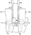
- FIG. 10is a side view in cross section of the ports of FIG. 7 , illustrating the placement of a spinal rod along the subcutaneous pathway between the ports and between bone anchors positioned in the ports;
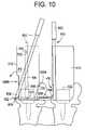
- FIG. 11is a side view in cross section of the ports of FIG. 7 , illustrating the spinal rod in position between the ports;
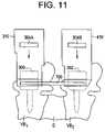
- FIG. 12is a front view of an exemplary embodiment of a surgical access port having an opening positioned between the distal end and the proximal end of the port;
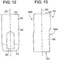
- FIG. 13is a side view of an exemplary embodiment of a surgical access port having a proximal opening and a distal opening.
- an elementmeans one element or more than one element.
- FIGS. 1-3illustrate an exemplary embodiment of a surgical access port 10 for providing posterior, lateral, or anterior access to the spine.
- the exemplary portincludes a proximal end 12 , a distal end 14 spaced apart a distance from the proximal end 12 and a sidewall 16 defining a lumen 18 extending from the proximal end 12 to the distal end 14 .
- the lumen 18has a length sufficient to at least span from a skin incision to proximate a vertebra.
- the exemplary port 10may include a first opening 30 formed in the sidewall 16 that defines a passageway for medical hardware, such as, for example, surgical instruments and/or implants, from the lumen to external to the port, as discussed in more detail below.
- the lumen 18 of the exemplary port 10provides unobstructed access from the proximal end of the lumen 18 to the distal end of the lumen 18 to permit the advancement of instruments and/or implants through the lumen 18 .
- the size and shape of the exemplary port 10may vary depending on the intended use of the port 10 , for example, the region of the spine, e.g., cervical, thoracic, or lumbar, the approach, e.g., posterior, lateral, or anterior, and the type(s) of implants and instruments desired to be positioned through the lumen 18 of the port 10 .
- the port 10may have a length l sufficient to span from a posterior skin incision to proximate a vertebra.
- the length l of the port 10may be varied, for example, depending on whether the port 10 is designed for use in the cervical, thoracic, or lumbar spine.
- the port 10may have a length l that allows the proximal end 12 of the port 10 to be positioned outside the patient's body, e.g., proximal to or parallel to the level of the skin, while the distal end 14 of the port 10 is in proximity to or abuts against a posterior surface of a vertebra.
- the exemplary port 10may have a cross-sectional shape and size that varies depending on the intended use of the port 10 , for example, the region of the spine, e.g., cervical, thoracic, or lumbar, and the type(s) of implants and instruments desired to be positioned through the lumen 18 of the port 10 .
- the exemplary port 10has a circular cross section.
- the port 110may have an elliptical or oval cross-section.
- the port 10may have a cross section that is circular, rectangular, square, elliptical, polygonal or any other shape suitable for providing surgical access to the spine.
- the port 10 and the port 100each have a generally constant cross section, e.g., the size and/or shape of the cross section of the port does not vary along the length l of the cannula.
- the cross section of the portmay vary in size and shape along the length l of the cannula.
- the width or diameter of the portmay vary along the length of the cannula.
- the port 10 and the port 100each have a continuous cross section in the manner of, for example, a cannula.
- the portmay have a non-continuous cross-section.
- the portmay have a C-shaped cross section or may include one or more longitudinally oriented slots that interrupt the cross section along the length l of the port.
- the distal end 14 of the port 10may be sized and shaped to facilitate engagement with the anatomy of the vertebra.
- the distal end 14may have a beveled, tapered, and/or angled shape.
- the lumen 18 of the exemplary port 10may have a diameter d that is sufficient to allow a spinal implant and/or instrument to be introduced therethrough.
- spinal implantsthat may be introduced through the port 10 include spinal fixation elements, such as a plate, rod, or tether, interbody fusion devices, nucleus replacement devices, artificial discs, and fasteners, such as bone anchors.
- the diameter d of the lumen 18may be sized to allow any of these implants and associated instruments to be introduced therethrough.
- the diameter d of the exemplary port 10may be sized to provide access to a portion of a first vertebra, for example, the pedicle, e.g., for placement of a bone anchor. In certain exemplary embodiments, the diameter d of the exemplary port 10 may be sized to span between a first vertebra and a second vertebra to provide access to the first vertebra, the second vertebra and the disk therebetween.
- the exemplary port 10may be constructed from any material suitable for use in vivo, including metals, such as stainless steel or titanium, polymers, ceramics, or composite materials.
- the port 10may be constructed from a translucent polymer.
- the outer surface of the sidewall 16 of the exemplary port 10may be contoured to minimize sharp edges and, thereby, inhibit injury to muscles and tissues surrounding the port 10 .
- the outer surface of the sidewall 16 of the port 10may include surface texturing to facilitate holding retracted tissue in place, in particular, away from the distal end of the lumen 18 .
- the surface texturingmay be, for example, one or more annular grooves 20 formed in the outer surface of the sidewall 16 of the port 10 .
- the surface texturingmay be surface roughening, ridges, spiral grooves, and/or materials with a high coefficient of friction.
- the outer surface of the sidewall 16 of the port 10is coated with silicon to facilitate holding retracted tissue.
- the proximal end 12 of the exemplary port 10may optionally include a positioning ring 24 that facilitates the positioning of the port 10 .
- the positioning ring 24may be generally annular in shape and may have an outer diameter that is greater that the diameter of the port 10 .
- the positioning ring 24in the exemplary port 10 , may have a tapered opening 26 that tapers to the diameter of the lumen 16 of the port to facilitate positioning of implants and instruments into the port 10 .
- the positioning ring 24may include one or more tabs 28 that facilitate connection of the positioning ring 24 and, thus, the port 10 , to a clamp, such as a C-arm.
- the exemplary port 10may be configured to hold a light source that illuminates the lumen 18 and/or the distal end 32 of the port 10 , for example, during a procedure performed in the port 10 .
- the proximal end 12may include a coupling mechanism, for example, a clamp, for hold one or more light sources, for example, a fiber optic cable or a light tube, that is oriented to illuminate the lumen and the distal end of the port 10 .
- one ore more light sourcesfor example, a fiber optic cable or a light tube, may be embedded within the sidewalls 16 of the port 10 to illuminate the lumen 18 and/or the distal end 14 of the port 10 .
- the exemplary port 10may include one or more openings 30 formed in the sidewall 16 of the port 10 .
- the port 10includes a single opening 30 formed in the sidewall 16 of the port 10 .
- the opening 30defines a passageway for medical hardware, for example spinal instruments and implants, between the lumen 18 and the exterior of the port 10 .
- medical hardwaremay be advanced subcutaneously from the lumen 18 to external to the port 10 , as indicated by arrow A in FIG. 3 .
- medical hardwaremay be advanced subcutaneously from exterior to the port 10 into the lumen 18 through the passageway, as indicated by arrow A′ in FIG. 3 .
- the opening 30in the exemplary port 10 , is an elongated slot extending proximally from the distal end 14 of the port 10 .
- the opening 30is oriented generally parallel to the longitudinal axis 22 of the port 10 and defines a passageway that is oriented approximately parallel to the longitudinal axis 22 of the port, as indicated by arrow A in FIG. 3 .
- the opening 30in the exemplary embodiment, has length l s and a width w s that are selected to allow at least a portion of a fixation element, such as a spinal rod, to be manipulated from within the lumen 18 through the passageway defined by the opening 30 .
- the opening 30is positioned at the distal end 14 of the port 10 and has an open, i.e., unobstructed, distal end 32 .
- FIGS. 4-6illustrate an exemplary embodiment of a surgical access port 110 having two openings 130 A, 130 B formed in a sidewall 116 of the port 110 to facilitate passage of medical hardware between the lumen 118 of the port 110 and the exterior of the port 110 .
- the size, shape, position, and number of the openings 130 A,Bmay be varied depending on, for example, the procedure selected and the medical hardware employed.
- the openings 130 A,Bmay be sized, shaped, and positioned to facilitate delivery of a spinal fixation element, such as a plate, rod, cable, or tether, to a site exterior to the port 110 or to receive a spinal fixation element delivered to the lumen 118 of the port 110 .
- a spinal fixation elementsuch as a plate, rod, cable, or tether
- the openings 130 A,B in the exemplary port 110are elongated slots extending proximally from the distal end 114 of the port 110 .
- the openings 130 A,Bin the illustrated embodiment, are oriented generally parallel to the longitudinal axis 122 of the port 110 .
- the openings 130 A, 130 Bare positioned generally opposite from each other, as illustrated in FIG. 6 , and each opening 130 A,B defines a passageway oriented approximately perpendicular to the longitudinal axis 122 of the port 110 for the passage of medical hardware, such as instruments or implants, out of the lumen 118 of the port 110 , as indicated by arrows B, and/or into the lumen 118 of the port, as indicated by arrows B′.
- the length l sa of the first opening 130 Ais less than the length lsb of second opening 130 B. In other exemplary embodiments, the length l sa of the first opening 130 A may be equal to the length lsb of second opening 130 B.
- FIG. 12illustrates another exemplary embodiment of a surgical access port 210 having an opening 230 formed in a sidewall of the port 210 .
- the opening 230 in the exemplary port 210is an elongated slot that is oriented approximately parallel to the longitudinal axis 222 of the port 120 and is positioned between the distal end 214 and the proximal end 212 of the port 210 .
- the opening 212is not open at the distal end thereof.
- the position of the opening 230 , as well as the size, shape, and number of opening(s)may be varied depending on, for example, the procedure selected and the medical hardware employed.
- the opening 230 in the illustrated embodimentis positioned proximate the distal end 214 of the port 210 .
- the opening 230may be positioned proximate the proximal end of the port 210 .
- FIG. 13illustrates an exemplary embodiment of a surgical access port 910 having a plurality of openings 930 A, 930 B formed in the sidewall 916 of the port 910 .
- the port 910includes a distal opening 930 A extending proximally from the distal end 914 of the port 910 and a proximal opening 930 B extending distally from the proximal end 912 of the port 910 .
- the distal opening 930 A and the proximal opening 903 Bare opposed from one another and overlap along at least a portion of the longitudinal axis 922 of the port 910 .
- opening(s)is not limited to the embodiments described above.
- the opening(s)may be circular, square, oval, or polygonal in shape and any number of openings may be employed.
- the portmay include indicia for indicating the location of the opening(s) on the port.
- the proximal end 12 of the exemplary port 10 illustrated in FIGS. 1-3may include one or more raised ridges 32 that indicate the position and orientation of the opening 30 in the sidewall 16 of the port 10 .
- a first ridge 32 Ais circumferentially aligned with the opening 30 and the second ridge 32 B is diametrically opposed to the opening 30 .
- indicia for indicating the position of the opening in the sidewall of the slotmay be a groove or mark on the proximal end and/or the sidewall or within the lumen of the port.
- a surgical access portsuch as any of the exemplary ports described above, may be inserted, for example through an incision, into proximity to a first vertebra of the spine.
- the distal end 14 of the surgical access port 10 illustrated in FIGS. 1-3may be advanced into proximity to the first vertebra to define a first pathway to the first vertebra through the lumen 18 of the surgical access port 10 .
- An instrument and/or implantmay be advanced through the lumen 18 of the port 10 into proximity to the first vertebra to perform a procedure at the first vertebra or to perform a procedure at a location proximal to the first vertebra.
- Such proceduresmay be performed by manipulating an instrument and/or implant within the lumen 18 of the port 10 and/or by manipulating the instrument and/or implant through an opening 30 in the sidewall of the port 10 .
- an instrument and/or an implantmay be advanced through the opening 30 to perform a procedure at the first vertebra or a position proximate the first vertebra, such as at a second vertebra that is adjacent to the first vertebra.
- Exemplary proceduresinclude laminotomy, facetectomy, foraminotomy, nerve root retraction, discectomy, and/or positioning of a spinal implant such as a spinal fixation element, such as a plate, rod, or tether, an interbody fusion device, a nucleus replacement device, an artificial disc, and a fastener, such as a bone anchor.
- a spinal implantsuch as a spinal fixation element, such as a plate, rod, or tether, an interbody fusion device, a nucleus replacement device, an artificial disc, and a fastener, such as a bone anchor.
- the distal end of a surgical access portmay be moved between two or more locations to perform procedures at multiple sites.
- the distal end 14 of the exemplary port 10may be advanced, e.g., through an incision, into proximity to a first and second vertebrae.
- the proximal end 12 of the port 10may be manipulated to move the distal end 14 into alignment with at least a portion of the first vertebra by, for example, angling the proximal end 12 relative to the skin incision in a procedure generally referred to as “wanding.”
- a proceduremay be performed at the first vertebra, such as, for example, placement of a first bone anchor in the first vertebra.
- the proximal end 12 of the port 10may be manipulated to move the distal end 14 into alignment with at least a portion of the second vertebra and a procedure may be performed at the second procedure, such as, for example, placement of a second bone anchor in the second vertebra.
- a fixation elementsuch as a spinal rod, may be coupled to the first and second bone anchors using the surgical access port.
- a first end of the fixation elementmay be positioned in the port and advanced through the lumen 16 to the opening 30 .
- the first end of the fixation elementmay be advanced subcutaneously through the opening 30 toward the first vertebra.
- the fixation elementmay be coupled to the second anchor by, for example, delivering a closure mechanism, such as a set screw or cap, through the port 10 to the second anchor.
- the proximal end 12 of the port 10may be manipulated to the move the distal end 14 into alignment with the first vertebra.
- the openingmay be aligned with the fixation element such that the distal end 14 moves along the fixation element toward the first vertebra.
- the fixation elementmay be advanced within the lumen of the port and subcutaneously through the opening(s) in the port using any conventional instrument for manipulating a spinal fixation element.
- the fixation elementmay be advanced through the lumen of the port in orientation substantially parallel to the longitudinal axis of the port.
- the fixation elementmay be manipulated through the opening(s) in the port to an orientation that is angled with respect to the longitudinal axis of the port.
- the fixation elementmay be oriented substantially perpendicular to the longitudinal axis of the port.
- Exemplary instruments for manipulating a spinal fixation element between two or more orientationsare disclosed in U.S. patent application Ser. No. 10/737,166, filed Dec. 16, 2004; U.S. patent application Ser. No. 10/737,538, filed Dec. 16, 2004; and U.S. Patent Application Ser. No. 60/542,548, filed Apr. 27, 2004, each of the aforementioned patent applications are incorporated herein by reference.
- two or more surgical access portsmay be employed to provide access to multiple sites proximate the spine.
- two surgical access portsmay be employed to facilitate subcutaneous placement of a spinal fixation element between to or more vertebrae.
- a first portsuch as exemplary port 10
- a first bone anchormay be advanced through the lumen 16 of the first port 10 to the first vertebra.
- a second portsuch as exemplary port 10
- a second bone anchormay be advanced through the lumen of the second port to the second vertebra.
- a spinal fixation elementfor example, a spinal rod, may be positioned in the lumen of the first port. An end of the spinal fixation element may advanced through an opening 30 of the first port 10 and advanced subcutaneously to an opening 30 in the second port.
- the spinal fixation elementmay be coupled to the first anchor by delivering a closure mechanism through the lumen 16 of the first port and to the second anchor by delivering a closure mechanism to the second anchor through the second port.
- FIGS. 7-11schematically illustrate an exemplary method of minimally invasive surgery that provides for the placement of multiple bone anchors and a fixation element on one or both sides of a patient's spine.
- the exemplary methodmay be employed to stabilize and align two or more bone segments, in particular, two vertebrae (VB 1 , VB 2 ), in a minimally invasive manner that reduces trauma to adjacent tissue.
- the exemplary methodmay comprise making a first incision in a patient and positioning a first surgical access port 310 , such as an exemplary surgical access port described above, in the first incision.
- the first port 310is analogous in construction to the exemplary surgical access port illustrated in FIGS. 4-6 and described above.
- the distal end 314 of the port 310is advanced into proximity to a first vertebra VB 1 and the lumen 316 of the first port 310 defines a first pathway from the incision to the first vertebra VB 1 .
- the first incisionmay be a minimally invasive incision made in the patient's skin that is expanded, for example, by retraction and or dilation, to create a pathway from the first incision to the proximate the first vertebra VB 1 .
- the first incision 14may be expanded to create the pathway in any conventional manner.
- the first incisionmay be expanded by dilation to the desired size, shape, and orientation.
- the first incisionmay be sequentially dilated using a plurality of dilators to create the pathway to the first vertebra. Exemplary methods and instruments for serial dilation are described in commonly owned U.S. Pat. No. 6,159,179, entitled Cannula and Sizing and Insertion Method; U.S. patent application Ser.
- a single dilatormay be employed to expand the incision.
- the first port 310may be positioned into the dilated first incision to define a first passageway to the vertebra.
- a retractormay be inserted into the dilated first incision to further expand the first incision and then the first port may be positioned in the first incision.
- the first incisionmay be expanded by inserting one or more retractors into the incision and expanding the incision to the desired size, shape, and orientation by expanding the retractor accordingly.
- Any type of conventional retractor or retractorsmay be employed to expand the first incision.
- suitable retractorsare described in commonly owned U.S. patent application Ser. No. 10/815,182, filed Mar. 31, 2004, entitled Telescoping Blade Assemblies and Instruments for Adjusting an Adjustable Blade; U.S. Provisional Patent Application Ser. No. 60/530,655, filed Dec. 18, 2003, entitled Surgical Retractor Systems, Illuminated Cannula and Methods of Use; and U.S. patent application Ser. No. 10/808,687, entitled Surgical Retractor Positioning Device, each of which are incorporated herein by reference.
- the first incisionmay be expanded to create a pathway by an intermuscular procedure that includes locating a muscle plane separating two muscles and separating the muscles at the muscle plane to create the first pathway.
- the intermuscular plane separating the multifidus and longissimus musclesmay be located through the first incision.
- the multifidus and longissimus musclesmay be separated at the muscle plane by blunt dissection, for example, by inserting a finger or an instrument, such as a retractor, through the muscle plane and advancing the finger or instrument to the vertebra to create the pathway to the vertebra.
- Intermuscular proceduresare described in detailed in U.S. Pat. No.
- the first incisionmay be a percutaneous skin incision that has a shape and extent that is less than, equal to, or slightly greater than, the extent of the instruments and implants being inserted thereto.
- the incisionmay be a stab incision that is expanded to facilitate positioning of the first port 310 therethrough.
- a first anchor 300may be advanced through the first pathway defined by the lumen 316 of the first port 310 to an anchor site on the first vertebra VB 1 .
- the first bone anchor 300may be any type of conventional bone anchor, including, for example, a monoaxial or polyaxial bone screw, a bolt, or a hook.
- the first bone anchor 300may be implanted into any portion of the first vertebra VB 1 respectively, in any conventional manner through the first incision. In the illustrated embodiment, the first bone anchor 300 is implanted into a first pedicle P 1 of the first vertebra VB 1 .
- a second surgical access port 410may be inserted through a second incision to define a second pathway from the second incision to a second vertebra VB 2 .
- the second port 410is analogous in construction to the first port except the second port 410 has a single opening 430 and the first port 310 has two openings 430 A, 430 B.
- the opening 430 in the second portmay be aligned with at least one of the openings 330 A, 330 B in the first port 310 by, for example, rotating one or both of the ports. Alignment indicia on the proximal end of the ports may be employed to facilitate alignment of the openings.
- the opening 430 in the second port 410is aligned with the opening 330 A of the first port 310 .
- the second incisionmay be expanded to create a pathway to the second vertebra VB 2 in a manner analogous to the first incision described above.
- the second incisionmay be a percutaneous skin incision in a manner analogous to the first incision.
- a second bone anchor 302e.g., a polyaxial bone screw analogous to the first bone anchor, may be advanced through the second pathway defined by the lumen 416 of the second port 410 to a second anchor site on the second vertebra VB 2 .
- the second bone anchor 302may be implanted into any portion of the second vertebra VB 2 respectively, in any conventional manner through the second incision.
- the second bone anchor 302is implanted into a second pedicle P 2 of the second vertebra VB 2 .
- a spinal fixation elementfor example, a spinal rod
- a first instrument 500may be employed for creating a subcutaneous pathway between the first port 310 and the second port 410 to facilitate advancement of the spinal fixation element to the second anchor 302 .
- the exemplary first instrument 500includes a proximal handle 502 , a shaft 504 having a longitudinal axis 506 , and a distal tip 508 that is oriented at an angle to the shaft 504 and is configured to dissect tissue.
- the shaft 504 of the exemplary instrumentis preferably sized to fit through the lumen of the first port 310 .
- the distal tip 508may be oriented at an angle greater than or equal to approximately 45° to the longitudinal axis 506 of the shaft 500 , and, in the illustrated embodiment, is oriented approximately perpendicular to the longitudinal axis 506 of the shaft 500 , although one skilled in the art will appreciate that other angles suitable for creating a subcutaneous pathway may be utilized.
- the distal tip 508in the illustrated embodiment, terminates at a tip 510 suitable for dissecting tissue.
- the length of the distal tip 508indicated by arrow 512 in FIG. 7 , may be varied depending on the procedure and the anatomy.
- the length of the distal tipis selected to span the distance between the distal end 314 of the first port 310 and the distal end of the second port 410 .
- the tip 510 of the instrument 500may be sized to interface with a bone anchor positioned in the first port 310 and/or the second port 410 .
- the tip 510 of the instrument 500may be sized to seat within the spinal fixation element receiving portion of the bone anchor.
- the tip 510 of the instrument 500may be sized to seat within the spinal rod receiving slot of the polyaxial bone screw.
- the spinal fixation elementmay have a tip configured to create a subcutaneous pathway.
- the fixation elementmay be a spinal rod having a tip suitable for tissue dissection. Advancement of the spinal rod to the second anchor may create the subcutaneous pathway between the first port 310 and the second port 410 .
- a second instrument 600may be used in cooperation with the first instrument 500 to facilitate the creation of a subcutaneous pathway between the distal end 314 of the first port 310 and the distal end 414 of the second port 410 .
- the exemplary second instrument 600includes a proximal handle 602 , a shaft 604 having a longitudinal axis 606 , and a distal tip 608 oriented at an angle to the longitudinal axis 606 of the shaft 604 .
- the shaft 604 of the exemplary second instrument 600is preferably sized to fit through the lumen 416 of the second port 610 .
- the distal tip 608 of the second instrument 600in the illustrated embodiment, is oriented approximately perpendicular to the longitudinal axis 606 of the shaft 600 , although one skilled in the art will appreciate that other angles suitable for creating a subcutaneous pathway may be utilized.
- the distal tip 608may be sized to receive at least a portion of the distal tip 508 of the first instrument 500 .
- the distal tip 608 of the second instrument 600may be generally arcuate in cross-section and may include a proximal surface 610 for receiving the distal tip 508 of the first instrument 500 .
- the proximal surface 610may be complementary in size and shape to the distal tip 508 of the first instrument 500 to facilitate alignment of the distal tip 508 of the first instrument 500 and the distal tip 608 of the second instrument 600 .
- the proximal surface 610may have a curvature analogous to the curvature of the distal tip 508 of the first instrument 500 .
- the distal tip 508 of the first instrument 500 and the distal tip 608 of the second instrument 600may be coaxially aligned when engaged with one another.
- the distal tip 608 of the second instrument 600may have other configurations suitable for receiving the distal tip 508 of the first instrument 500 .
- the distal tip 508 of the first instrument 500is advanced to the opening 430 in the second port 410 and into the distal tip 608 of the second instrument 600 , thereby creating the subcutaneous pathway.
- the first instrument 500 and the second instrument 600may be cooperatively manipulated to facilitate creation and expansion of the subcutaneous pathway between the distal end 314 of the first port 310 and the distal end 414 of the second port 410 .
- the proximal handle 502 of the first instrument 500 and the proximal handle 602 of the second instrument 600may be moved in unison to cause the distal tips 508 , 608 to move in unison between the distal ends of the first and second ports 310 , 410 .
- a spinal fixation elementfor example a spinal rod 700
- an exemplary spinal rod manipulating instrument 800includes a proximal handle 802 , a shaft 804 , and a distal end 806 that may be pivotally connected at a pivot point 810 to a first end 702 of the exemplary spinal rod 700 .
- the exemplary rod manipulating instrument 800allows the rod 700 to be positioned in the first port 310 in an orientation approximately parallel to the longitudinal axis of the first port 310 and to be pivoted to a non-parallel orientation to facilitate advancement of the rod 700 through a distal opening 330 in the port 310 .
- the rod 70may be pivoted to an orientation that is substantially perpendicular to the longitudinal axis of the first port 310 to allow the second end 704 of the rod 700 to be advanced through the opening 330 A and subcutaneously to the second port 410 , as illustrated in FIG. 10 .
- the port 310is provided with two opposed openings 330 A,B to facilitate transition of the rod 700 to an orientation suitable for subcutaneous advancement of the rod.
- the opening 330 Aallows the first end 702 of the rod 700 to be pivoted to a non-parallel orientation, as illustrated by arrow P in FIG. 10 .
- the manipulating instrument 800may be employed to facilitate subcutaneous advancement of the rod 700 to the second port 410 .
- the second instrument 600also may be employed to facilitate subcutaneous advancement of the rod 700 to the second port 410 , as illustrated in FIG. 10 .
- the distal tip 608 of the second instrument 600may receive a portion of the rod 700 , for example, the second end 704 of the rod 700 , and may guide the rod 700 along the subcutaneous pathway to the second port 410 .
- use of the second instrument 600is optional and that in certain exemplary embodiments the rod 700 , or other fixation element, may be advanced to the second port 410 independent of an instrument positioned in the second port 410 .
- the subcutaneous pathway between the first port and the second portmay be created before advancing the first anchor through the first port and before advancing the second anchor through the second port.
- the subcutaneous pathwaymay be created after advancing the first anchor through the first port and before advancing the second anchor through the second port.
- the first port and the second portmay be placed before advancement of the first anchor and the second anchor through the ports.
Landscapes
- Health & Medical Sciences (AREA)
- Life Sciences & Earth Sciences (AREA)
- General Health & Medical Sciences (AREA)
- Engineering & Computer Science (AREA)
- Biomedical Technology (AREA)
- Heart & Thoracic Surgery (AREA)
- Animal Behavior & Ethology (AREA)
- Public Health (AREA)
- Veterinary Medicine (AREA)
- Surgery (AREA)
- Orthopedic Medicine & Surgery (AREA)
- Hematology (AREA)
- Anesthesiology (AREA)
- Neurology (AREA)
- Medical Informatics (AREA)
- Nuclear Medicine, Radiotherapy & Molecular Imaging (AREA)
- Molecular Biology (AREA)
- Vascular Medicine (AREA)
- Surgical Instruments (AREA)
- Prostheses (AREA)
Abstract
Description
Claims (30)
Priority Applications (3)
| Application Number | Priority Date | Filing Date | Title |
|---|---|---|---|
| US10/914,983US7824410B2 (en) | 2001-10-30 | 2004-08-10 | Instruments and methods for minimally invasive spine surgery |
| US12/909,158US8444678B2 (en) | 2001-10-30 | 2010-10-21 | Instruments and methods for minimally invasive spine surgery |
| US13/889,768US9226782B2 (en) | 2001-10-30 | 2013-05-08 | Instruments and methods for minimally invasive spine surgery |
Applications Claiming Priority (3)
| Application Number | Priority Date | Filing Date | Title |
|---|---|---|---|
| US10/024,221US6916330B2 (en) | 2001-10-30 | 2001-10-30 | Non cannulated dilators |
| US10/021,809US7008431B2 (en) | 2001-10-30 | 2001-10-30 | Configured and sized cannula |
| US10/914,983US7824410B2 (en) | 2001-10-30 | 2004-08-10 | Instruments and methods for minimally invasive spine surgery |
Related Parent Applications (1)
| Application Number | Title | Priority Date | Filing Date |
|---|---|---|---|
| US10/021,809Continuation-In-PartUS7008431B2 (en) | 2001-10-30 | 2001-10-30 | Configured and sized cannula |
Related Child Applications (1)
| Application Number | Title | Priority Date | Filing Date |
|---|---|---|---|
| US12/909,158ContinuationUS8444678B2 (en) | 2001-10-30 | 2010-10-21 | Instruments and methods for minimally invasive spine surgery |
Publications (2)
| Publication Number | Publication Date |
|---|---|
| US20050080418A1 US20050080418A1 (en) | 2005-04-14 |
| US7824410B2true US7824410B2 (en) | 2010-11-02 |
Family
ID=46302517
Family Applications (3)
| Application Number | Title | Priority Date | Filing Date |
|---|---|---|---|
| US10/914,983Active2026-01-05US7824410B2 (en) | 2001-10-30 | 2004-08-10 | Instruments and methods for minimally invasive spine surgery |
| US12/909,158Expired - Fee RelatedUS8444678B2 (en) | 2001-10-30 | 2010-10-21 | Instruments and methods for minimally invasive spine surgery |
| US13/889,768Expired - Fee RelatedUS9226782B2 (en) | 2001-10-30 | 2013-05-08 | Instruments and methods for minimally invasive spine surgery |
Family Applications After (2)
| Application Number | Title | Priority Date | Filing Date |
|---|---|---|---|
| US12/909,158Expired - Fee RelatedUS8444678B2 (en) | 2001-10-30 | 2010-10-21 | Instruments and methods for minimally invasive spine surgery |
| US13/889,768Expired - Fee RelatedUS9226782B2 (en) | 2001-10-30 | 2013-05-08 | Instruments and methods for minimally invasive spine surgery |
Country Status (1)
| Country | Link |
|---|---|
| US (3) | US7824410B2 (en) |
Cited By (88)
| Publication number | Priority date | Publication date | Assignee | Title |
|---|---|---|---|---|
| US20100087866A1 (en)* | 2008-10-03 | 2010-04-08 | Trace Cawley | Minimally invasive surgery pedicle screw system |
| US20110218581A1 (en)* | 2010-03-02 | 2011-09-08 | Warsaw Orthopedic, Inc. | Systems and methods for minimally invasive surgical procedures |
| USD656610S1 (en) | 2009-02-06 | 2012-03-27 | Kleiner Jeffrey B | Spinal distraction instrument |
| US8216282B2 (en) | 2008-10-01 | 2012-07-10 | Sherwin Hua | System and method for wire-guided pedicle screw stabilization of spinal vertebrae |
| US8277510B2 (en) | 2008-02-06 | 2012-10-02 | Kleiner Intellectual Property, Llc | Tools and methods for spinal fusion |
| US8333770B2 (en) | 2008-10-01 | 2012-12-18 | Sherwin Hua | Systems and methods for pedicle screw stabilization of spinal vertebrae |
| US20120323278A1 (en)* | 2011-06-16 | 2012-12-20 | Industrial Technology Research Institute | Minimally invasive spinal stabilization system |
| US8337532B1 (en) | 2011-12-08 | 2012-12-25 | Spine Wave, Inc. | Methods for percutaneously extending an existing spinal construct |
| US8361151B2 (en) | 2001-10-30 | 2013-01-29 | Depuy Spine, Inc. | Configured and sized cannula |
| US8394129B2 (en) | 2011-03-10 | 2013-03-12 | Interventional Spine, Inc. | Method and apparatus for minimally invasive insertion of intervertebral implants |
| US8444678B2 (en) | 2001-10-30 | 2013-05-21 | Depuy Spine, Inc. | Instruments and methods for minimally invasive spine surgery |
| US8518087B2 (en) | 2011-03-10 | 2013-08-27 | Interventional Spine, Inc. | Method and apparatus for minimally invasive insertion of intervertebral implants |
| US8603094B2 (en) | 2010-07-26 | 2013-12-10 | Spinal Usa, Inc. | Minimally invasive surgical tower access devices and related methods |
| US8685031B2 (en) | 2009-09-18 | 2014-04-01 | Spinal Surgical Strategies, Llc | Bone graft delivery system |
| US8864654B2 (en) | 2010-04-20 | 2014-10-21 | Jeffrey B. Kleiner | Method and apparatus for performing retro peritoneal dissection |
| US8870882B2 (en) | 2008-12-05 | 2014-10-28 | Jeffrey KLEINER | Apparatus and method of spinal implant and fusion |
| US8870879B2 (en) | 2011-06-16 | 2014-10-28 | Industrial Technology Research Institute | Minimally invasive spinal stabilization method |
| US8906028B2 (en) | 2009-09-18 | 2014-12-09 | Spinal Surgical Strategies, Llc | Bone graft delivery device and method of using the same |
| USD723682S1 (en) | 2013-05-03 | 2015-03-03 | Spinal Surgical Strategies, Llc | Bone graft delivery tool |
| USRE45571E1 (en) | 1999-03-12 | 2015-06-23 | DePuy Synthes Products, Inc. | Cannula and sizing insertion method |
| US9060877B2 (en) | 2009-09-18 | 2015-06-23 | Spinal Surgical Strategies, Llc | Fusion cage with combined biological delivery system |
| US9173694B2 (en) | 2009-09-18 | 2015-11-03 | Spinal Surgical Strategies, Llc | Fusion cage with combined biological delivery system |
| US9186193B2 (en) | 2009-09-18 | 2015-11-17 | Spinal Surgical Strategies, Llc | Fusion cage with combined biological delivery system |
| US9247943B1 (en) | 2009-02-06 | 2016-02-02 | Kleiner Intellectual Property, Llc | Devices and methods for preparing an intervertebral workspace |
| USD750249S1 (en) | 2014-10-20 | 2016-02-23 | Spinal Surgical Strategies, Llc | Expandable fusion cage |
| US9277928B2 (en) | 2013-03-11 | 2016-03-08 | Interventional Spine, Inc. | Method and apparatus for minimally invasive insertion of intervertebral implants |
| US9522070B2 (en) | 2013-03-07 | 2016-12-20 | Interventional Spine, Inc. | Intervertebral implant |
| US9596428B2 (en) | 2010-03-26 | 2017-03-14 | Echostar Technologies L.L.C. | Multiple input television receiver |
| US9629729B2 (en) | 2009-09-18 | 2017-04-25 | Spinal Surgical Strategies, Llc | Biological delivery system with adaptable fusion cage interface |
| US9717403B2 (en) | 2008-12-05 | 2017-08-01 | Jeffrey B. Kleiner | Method and apparatus for performing retro peritoneal dissection |
| US9750546B2 (en) | 2014-08-11 | 2017-09-05 | Spinal Elements, Inc. | Articulating rod inserter |
| USD797290S1 (en) | 2015-10-19 | 2017-09-12 | Spinal Surgical Strategies, Llc | Bone graft delivery tool |
| US9788856B2 (en) | 2014-03-11 | 2017-10-17 | Stryker European Holdings I, Llc | Endoscopic surgical systems and methods |
| US9808598B2 (en) | 2015-02-04 | 2017-11-07 | Teleflex Medical Incorporated | Flexible tip dilator |
| US9839530B2 (en) | 2007-06-26 | 2017-12-12 | DePuy Synthes Products, Inc. | Highly lordosed fusion cage |
| US9883951B2 (en) | 2012-08-30 | 2018-02-06 | Interventional Spine, Inc. | Artificial disc |
| US9895236B2 (en) | 2010-06-24 | 2018-02-20 | DePuy Synthes Products, Inc. | Enhanced cage insertion assembly |
| US9913727B2 (en) | 2015-07-02 | 2018-03-13 | Medos International Sarl | Expandable implant |
| US9931223B2 (en) | 2008-04-05 | 2018-04-03 | DePuy Synthes Products, Inc. | Expandable intervertebral implant |
| US9968348B2 (en) | 2013-02-25 | 2018-05-15 | DePuy Synthes Products, Inc. | Surgical access tube |
| US9993349B2 (en) | 2002-06-27 | 2018-06-12 | DePuy Synthes Products, Inc. | Intervertebral disc |
| US9993353B2 (en) | 2013-03-14 | 2018-06-12 | DePuy Synthes Products, Inc. | Method and apparatus for minimally invasive insertion of intervertebral implants |
| US10058433B2 (en) | 2012-07-26 | 2018-08-28 | DePuy Synthes Products, Inc. | Expandable implant |
| US10085778B2 (en) | 2016-03-04 | 2018-10-02 | Spinal Elements, Inc. | Rod reducer instrument for spinal surgery |
| US10245159B1 (en) | 2009-09-18 | 2019-04-02 | Spinal Surgical Strategies, Llc | Bone graft delivery system and method for using same |
| USD853560S1 (en) | 2008-10-09 | 2019-07-09 | Nuvasive, Inc. | Spinal implant insertion device |
| US10369015B2 (en) | 2010-09-23 | 2019-08-06 | DePuy Synthes Products, Inc. | Implant inserter having a laterally-extending dovetail engagement feature |
| US10390963B2 (en) | 2006-12-07 | 2019-08-27 | DePuy Synthes Products, Inc. | Intervertebral implant |
| US10398563B2 (en) | 2017-05-08 | 2019-09-03 | Medos International Sarl | Expandable cage |
| US10433977B2 (en) | 2008-01-17 | 2019-10-08 | DePuy Synthes Products, Inc. | Expandable intervertebral implant and associated method of manufacturing the same |
| US10500062B2 (en) | 2009-12-10 | 2019-12-10 | DePuy Synthes Products, Inc. | Bellows-like expandable interbody fusion cage |
| US10537436B2 (en) | 2016-11-01 | 2020-01-21 | DePuy Synthes Products, Inc. | Curved expandable cage |
| US10548741B2 (en) | 2010-06-29 | 2020-02-04 | DePuy Synthes Products, Inc. | Distractible intervertebral implant |
| US10888433B2 (en) | 2016-12-14 | 2021-01-12 | DePuy Synthes Products, Inc. | Intervertebral implant inserter and related methods |
| US10940016B2 (en) | 2017-07-05 | 2021-03-09 | Medos International Sarl | Expandable intervertebral fusion cage |
| US10973656B2 (en) | 2009-09-18 | 2021-04-13 | Spinal Surgical Strategies, Inc. | Bone graft delivery system and method for using same |
| US11026627B2 (en) | 2013-03-15 | 2021-06-08 | Cadwell Laboratories, Inc. | Surgical instruments for determining a location of a nerve during a procedure |
| US20210212723A1 (en)* | 2009-05-20 | 2021-07-15 | DePuy Synthes Products, Inc. | Patient-Mounted Retraction |
| US11160580B2 (en) | 2019-04-24 | 2021-11-02 | Spine23 Inc. | Systems and methods for pedicle screw stabilization of spinal vertebrae |
| US11177610B2 (en) | 2017-01-23 | 2021-11-16 | Cadwell Laboratories, ino. | Neuromonitoring connection system |
| US11253182B2 (en) | 2018-05-04 | 2022-02-22 | Cadwell Laboratories, Inc. | Apparatus and method for polyphasic multi-output constant-current and constant-voltage neurophysiological stimulation |
| US11344424B2 (en) | 2017-06-14 | 2022-05-31 | Medos International Sarl | Expandable intervertebral implant and related methods |
| USD956223S1 (en) | 2020-05-12 | 2022-06-28 | Innovasis, Inc. | Surgical retractor |
| USD956225S1 (en) | 2020-05-12 | 2022-06-28 | Innovasis, Inc. | Surgical retractor |
| USD956224S1 (en) | 2020-05-12 | 2022-06-28 | Innovasis, Inc. | Surgical retractor |
| US11426286B2 (en) | 2020-03-06 | 2022-08-30 | Eit Emerging Implant Technologies Gmbh | Expandable intervertebral implant |
| US11426290B2 (en) | 2015-03-06 | 2022-08-30 | DePuy Synthes Products, Inc. | Expandable intervertebral implant, system, kit and method |
| US11432810B2 (en) | 2020-05-12 | 2022-09-06 | Innovasis, Inc. | Systems and methods for surgical retraction |
| US11443649B2 (en) | 2018-06-29 | 2022-09-13 | Cadwell Laboratories, Inc. | Neurophysiological monitoring training simulator |
| US11446156B2 (en) | 2018-10-25 | 2022-09-20 | Medos International Sarl | Expandable intervertebral implant, inserter instrument, and related methods |
| US11452607B2 (en) | 2010-10-11 | 2022-09-27 | DePuy Synthes Products, Inc. | Expandable interspinous process spacer implant |
| US11510788B2 (en) | 2016-06-28 | 2022-11-29 | Eit Emerging Implant Technologies Gmbh | Expandable, angularly adjustable intervertebral cages |
| US11529133B2 (en) | 2019-09-11 | 2022-12-20 | K2M, Inc. | Surgical access instrument |
| US11596522B2 (en) | 2016-06-28 | 2023-03-07 | Eit Emerging Implant Technologies Gmbh | Expandable and angularly adjustable intervertebral cages with articulating joint |
| US11612491B2 (en) | 2009-03-30 | 2023-03-28 | DePuy Synthes Products, Inc. | Zero profile spinal fusion cage |
| US11666455B2 (en) | 2009-09-18 | 2023-06-06 | Spinal Surgical Strategies, Inc., A Nevada Corporation | Bone graft delivery devices, systems and kits |
| US11752009B2 (en) | 2021-04-06 | 2023-09-12 | Medos International Sarl | Expandable intervertebral fusion cage |
| US11850160B2 (en) | 2021-03-26 | 2023-12-26 | Medos International Sarl | Expandable lordotic intervertebral fusion cage |
| US11911287B2 (en) | 2010-06-24 | 2024-02-27 | DePuy Synthes Products, Inc. | Lateral spondylolisthesis reduction cage |
| USRE49973E1 (en) | 2013-02-28 | 2024-05-21 | DePuy Synthes Products, Inc. | Expandable intervertebral implant, system, kit and method |
| US11992339B2 (en) | 2018-05-04 | 2024-05-28 | Cadwell Laboratories, Inc. | Systems and methods for dynamic neurophysiological stimulation |
| US12076058B2 (en) | 2021-05-12 | 2024-09-03 | Spine23 Inc. | Systems and methods for pedicle screw stabilization of spinal vertebrae |
| US12090064B2 (en) | 2022-03-01 | 2024-09-17 | Medos International Sarl | Stabilization members for expandable intervertebral implants, and related systems and methods |
| US12268422B2 (en) | 2019-11-27 | 2025-04-08 | Spine23 Inc. | Systems, devices and methods for treating a lateral curvature of a spine |
| US12279972B2 (en) | 2008-05-22 | 2025-04-22 | Spinal Surgical Strategies, Inc. | Spinal fusion cage system with inserter |
| USD1076077S1 (en)* | 2023-04-25 | 2025-05-20 | Adam Isaac Lewis | Retractor tube |
| US12324610B2 (en) | 2021-04-28 | 2025-06-10 | Spinal Elements, Inc. | Lever reducer |
| US12440346B2 (en) | 2023-03-31 | 2025-10-14 | DePuy Synthes Products, Inc. | Expandable intervertebral implant |
Families Citing this family (107)
| Publication number | Priority date | Publication date | Assignee | Title |
|---|---|---|---|---|
| EP1417000B1 (en) | 2001-07-11 | 2018-07-11 | Nuvasive, Inc. | System for determining nerve proximity during surgery |
| JP2005503857A (en) | 2001-09-25 | 2005-02-10 | ヌバシブ, インコーポレイテッド | Systems and methods for performing surgical procedures and surgical diagnosis |
| US6916330B2 (en)* | 2001-10-30 | 2005-07-12 | Depuy Spine, Inc. | Non cannulated dilators |
| WO2003057051A1 (en)* | 2002-01-09 | 2003-07-17 | Synthes Ag Chur | Device for drilling or for inserting implants |
| US8147421B2 (en) | 2003-01-15 | 2012-04-03 | Nuvasive, Inc. | System and methods for determining nerve direction to a surgical instrument |
| US9259144B2 (en)* | 2002-07-11 | 2016-02-16 | Nuvasive, Inc. | Surgical access system and related methods |
| US7014608B2 (en)* | 2002-12-13 | 2006-03-21 | Synthes Spine Company, Lp | Guided retractor and methods of use |
| US20040116777A1 (en)* | 2002-12-13 | 2004-06-17 | Jeffrey Larson | Guided retractor and methods of use |
| US20060155170A1 (en)* | 2002-12-13 | 2006-07-13 | Synthes Spine Company, Lp | Guided retractor and methods of use |
| US7955355B2 (en) | 2003-09-24 | 2011-06-07 | Stryker Spine | Methods and devices for improving percutaneous access in minimally invasive surgeries |
| US8002798B2 (en) | 2003-09-24 | 2011-08-23 | Stryker Spine | System and method for spinal implant placement |
| US7588575B2 (en) | 2003-10-21 | 2009-09-15 | Innovative Spinal Technologies | Extension for use with stabilization systems for internal structures |
| US7967826B2 (en)* | 2003-10-21 | 2011-06-28 | Theken Spine, Llc | Connector transfer tool for internal structure stabilization systems |
| US7588588B2 (en) | 2003-10-21 | 2009-09-15 | Innovative Spinal Technologies | System and method for stabilizing of internal structures |
| US9055934B2 (en)* | 2004-08-26 | 2015-06-16 | Zimmer Spine, Inc. | Methods and apparatus for access to and/or treatment of the spine |
| US7144368B2 (en)* | 2003-11-26 | 2006-12-05 | Synthes Spine Company, Lp | Guided retractor and methods of use |
| US7527638B2 (en) | 2003-12-16 | 2009-05-05 | Depuy Spine, Inc. | Methods and devices for minimally invasive spinal fixation element placement |
| US7666188B2 (en) | 2003-12-16 | 2010-02-23 | Depuy Spine, Inc. | Methods and devices for spinal fixation element placement |
| US7776051B2 (en)* | 2004-05-03 | 2010-08-17 | Theken Spine, Llc | System and method for displacement of bony structures |
| US7666189B2 (en)* | 2004-09-29 | 2010-02-23 | Synthes Usa, Llc | Less invasive surgical system and methods |
| US8267969B2 (en) | 2004-10-20 | 2012-09-18 | Exactech, Inc. | Screw systems and methods for use in stabilization of bone structures |
| US7935134B2 (en)* | 2004-10-20 | 2011-05-03 | Exactech, Inc. | Systems and methods for stabilization of bone structures |
| US8162985B2 (en)* | 2004-10-20 | 2012-04-24 | The Board Of Trustees Of The Leland Stanford Junior University | Systems and methods for posterior dynamic stabilization of the spine |
| US8226690B2 (en) | 2005-07-22 | 2012-07-24 | The Board Of Trustees Of The Leland Stanford Junior University | Systems and methods for stabilization of bone structures |
| US20070239159A1 (en)* | 2005-07-22 | 2007-10-11 | Vertiflex, Inc. | Systems and methods for stabilization of bone structures |
| US8025680B2 (en) | 2004-10-20 | 2011-09-27 | Exactech, Inc. | Systems and methods for posterior dynamic stabilization of the spine |
| US7651499B2 (en) | 2004-10-26 | 2010-01-26 | Concept Matrix, Llc | Working channel for minimally invasive spine surgery |
| US8075591B2 (en) | 2004-11-09 | 2011-12-13 | Depuy Spine, Inc. | Minimally invasive spinal fixation guide systems and methods |
| US7569061B2 (en) | 2004-11-16 | 2009-08-04 | Innovative Spinal Technologies, Inc. | Off-axis anchor guidance system |
| WO2006084194A2 (en)* | 2005-02-02 | 2006-08-10 | Nuvasive, Inc. | System and methods for monitoring during anterior surgery |
| WO2008024937A2 (en) | 2006-08-23 | 2008-02-28 | Pioneer Surgical Technology, Inc. | Minimally invasive surgical system |
| EP1858422A4 (en) | 2005-02-23 | 2011-12-28 | Pioneer Surgical Technology Inc | Minimally invasive surgical system |
| US7758617B2 (en)* | 2005-04-27 | 2010-07-20 | Globus Medical, Inc. | Percutaneous vertebral stabilization system |
| US9314273B2 (en) | 2005-04-27 | 2016-04-19 | Globus Medical, Inc. | Percutaneous vertebral stabilization system |
| US8961548B2 (en)* | 2005-06-06 | 2015-02-24 | Laprostop, Llc | Safety stop trochar device and system |
| US8083773B2 (en)* | 2005-07-15 | 2011-12-27 | Muhammad Abubakar Atiq Durrani | Apparatus for minimally invasive posterior correction of spinal deformity |
| US8740783B2 (en)* | 2005-07-20 | 2014-06-03 | Nuvasive, Inc. | System and methods for performing neurophysiologic assessments with pressure monitoring |
| US8523865B2 (en) | 2005-07-22 | 2013-09-03 | Exactech, Inc. | Tissue splitter |
| US7909830B2 (en)* | 2005-08-25 | 2011-03-22 | Synthes Usa, Llc | Methods of spinal fixation and instrumentation |
| US7695475B2 (en)* | 2005-08-26 | 2010-04-13 | Warsaw Orthopedic, Inc. | Instruments for minimally invasive stabilization of bony structures |
| WO2007038290A2 (en) | 2005-09-22 | 2007-04-05 | Nuvasive, Inc. | Multi-channel stimulation threshold detection algorithm for use in neurophysiology monitoring |
| US8568317B1 (en) | 2005-09-27 | 2013-10-29 | Nuvasive, Inc. | System and methods for nerve monitoring |
| US8251902B2 (en) | 2005-10-17 | 2012-08-28 | Lanx, Inc. | Pedicle guided retractor system |
| US7927360B2 (en)* | 2006-01-26 | 2011-04-19 | Warsaw Orthopedic, Inc. | Spinal anchor assemblies having extended receivers |
| EP1981422B1 (en) | 2006-02-06 | 2018-10-24 | Stryker European Holdings I, LLC | Rod contouring apparatus for percutaneous pedicle screw extension |
| US7520879B2 (en)* | 2006-02-07 | 2009-04-21 | Warsaw Orthopedic, Inc. | Surgical instruments and techniques for percutaneous placement of spinal stabilization elements |
| WO2007121271A2 (en)* | 2006-04-11 | 2007-10-25 | Synthes (U.S.A) | Minimally invasive fixation system |
| US8114085B2 (en)* | 2006-04-13 | 2012-02-14 | General Electric Company | Percutaneous registration-and-access tool for minimally invasive spinal surgery |
| US20080015601A1 (en)* | 2006-06-14 | 2008-01-17 | Michael Castro | Reduction device and method of use |
| US7686809B2 (en) | 2006-09-25 | 2010-03-30 | Stryker Spine | Rod inserter and rod with reduced diameter end |
| US8038699B2 (en) | 2006-09-26 | 2011-10-18 | Ebi, Llc | Percutaneous instrument assembly |
| US7918857B2 (en) | 2006-09-26 | 2011-04-05 | Depuy Spine, Inc. | Minimally invasive bone anchor extensions |
| US8162952B2 (en) | 2006-09-26 | 2012-04-24 | Ebi, Llc | Percutaneous instrument assembly |
| US8096996B2 (en) | 2007-03-20 | 2012-01-17 | Exactech, Inc. | Rod reducer |
| US8262662B2 (en)* | 2006-11-20 | 2012-09-11 | Depuy Spine, Inc. | Break-off screw extensions |
| US8529570B2 (en)* | 2006-12-15 | 2013-09-10 | The Adelman Research Ltd | Technique and device for laminar osteotomy and laminoplasty |
| US7947046B2 (en)* | 2007-06-21 | 2011-05-24 | Warsaw Orthopedic, Inc. | Anchor extenders for minimally invasive surgical procedures |
| US8043343B2 (en)* | 2007-06-28 | 2011-10-25 | Zimmer Spine, Inc. | Stabilization system and method |
| US8623019B2 (en) | 2007-07-03 | 2014-01-07 | Pioneer Surgical Technology, Inc. | Bone plate system |
| US8361126B2 (en) | 2007-07-03 | 2013-01-29 | Pioneer Surgical Technology, Inc. | Bone plate system |
| US8414588B2 (en) | 2007-10-04 | 2013-04-09 | Depuy Spine, Inc. | Methods and devices for minimally invasive spinal connection element delivery |
| US20090171392A1 (en)* | 2007-12-04 | 2009-07-02 | Javier Garcia-Bengochea | Guide wire mounting collar for spinal fixation using minimally invasive surgical techniques |
| US8540720B2 (en)* | 2007-12-06 | 2013-09-24 | Javier Garcia-Bengochea | System, instrumentation and method for spinal fixation using minimally invasive surgical techniques |
| US8226656B2 (en)* | 2008-04-16 | 2012-07-24 | Warsaw Orthopedic, Inc. | Minimally invasive systems and methods for insertion of a connecting member adjacent the spinal column |
| US8496661B2 (en)* | 2008-11-03 | 2013-07-30 | Omni Surgical LLC | System and method for micro-invasive transfacet lumbar interbody fusion |
| US8197405B2 (en)* | 2008-12-03 | 2012-06-12 | Depuy Products, Inc. | Surgical retractor assembly and associated method of use |
| US9655658B2 (en) | 2009-10-14 | 2017-05-23 | Ebi, Llc | Deformable device for minimally invasive fixation |
| DE102010016448A1 (en)* | 2010-04-14 | 2011-10-20 | Aesculap Ag | Orthopedic fixation system and target device for such a fixation system |
| US8535318B2 (en) | 2010-04-23 | 2013-09-17 | DePuy Synthes Products, LLC | Minimally invasive instrument set, devices and related methods |
| US8454664B2 (en) | 2010-06-18 | 2013-06-04 | Spine Wave, Inc. | Method for fixing a connecting rod to a thoracic spine |
| US8512383B2 (en) | 2010-06-18 | 2013-08-20 | Spine Wave, Inc. | Method of percutaneously fixing a connecting rod to a spine |
| US8394108B2 (en) | 2010-06-18 | 2013-03-12 | Spine Wave, Inc. | Screw driver for a multiaxial bone screw |
| US8206395B2 (en) | 2010-06-18 | 2012-06-26 | Spine Wave, Inc. | Surgical instrument and method for the distraction or compression of bones |
| US8777954B2 (en) | 2010-06-18 | 2014-07-15 | Spine Wave, Inc. | Pedicle screw extension for use in percutaneous spinal fixation |
| US20120130193A1 (en)* | 2010-11-22 | 2012-05-24 | Fiona Middlemiss Haig | Two Part Thoracic Port Assembly |
| US8828059B2 (en) | 2011-04-25 | 2014-09-09 | Warsaw Orthopedic, Inc. | Elongated connecting elements for minimally invasive surgical procedures |
| US8617218B2 (en) | 2011-05-13 | 2013-12-31 | Warsaw Orthoepdic, Inc. | Bone anchor extenders |
| CN103717159B (en) | 2011-05-27 | 2016-08-17 | 新特斯有限责任公司 | Minimally Invasive Spinal Fixation System Including Vertebral Alignment Features |
| US9622779B2 (en) | 2011-10-27 | 2017-04-18 | DePuy Synthes Products, Inc. | Method and devices for a sub-splenius / supra-levator scapulae surgical access technique |
| US9198769B2 (en) | 2011-12-23 | 2015-12-01 | Pioneer Surgical Technology, Inc. | Bone anchor assembly, bone plate system, and method |
| US9084591B2 (en) | 2012-10-23 | 2015-07-21 | Neurostructures, Inc. | Retractor |
| US20140121467A1 (en)* | 2012-10-31 | 2014-05-01 | Invuity, Inc. | Methods and apparatus for simultaneous retraction and distraction of bone and soft tissue |
| CA2846149C (en) | 2013-03-14 | 2018-03-20 | Stryker Spine | Systems and methods for percutaneous spinal fusion |
| US9827020B2 (en) | 2013-03-14 | 2017-11-28 | Stryker European Holdings I, Llc | Percutaneous spinal cross link system and method |
| US9480504B1 (en)* | 2013-03-15 | 2016-11-01 | Nuvasive, Inc. | Spinal alignment frame |
| US20140350345A1 (en)* | 2013-05-23 | 2014-11-27 | Thomas Frederick Helmsworth | Device to accommodate multiple ports through a single incision for laparoscopic surgery |
| US9295500B2 (en) | 2013-06-12 | 2016-03-29 | Spine Wave, Inc. | Screw driver with release for a multiaxial bone screw |
| US9744050B1 (en) | 2013-12-06 | 2017-08-29 | Stryker European Holdings I, Llc | Compression and distraction system for percutaneous posterior spinal fusion |
| US10159579B1 (en) | 2013-12-06 | 2018-12-25 | Stryker European Holdings I, Llc | Tubular instruments for percutaneous posterior spinal fusion systems and methods |
| US9408716B1 (en) | 2013-12-06 | 2016-08-09 | Stryker European Holdings I, Llc | Percutaneous posterior spinal fusion implant construction and method |
| US9339263B2 (en)* | 2014-01-03 | 2016-05-17 | DePuy Synthes Products, Inc. | Dilation system and method |
| US10022172B2 (en)* | 2014-06-25 | 2018-07-17 | Spine Wave, Inc. | Minimally invasive posterolateral fusion |
| EP3164080A4 (en) | 2014-07-06 | 2018-06-27 | Garcia-Bengochea, Javier | Methods and devices for surgical access |
| WO2017008087A1 (en) | 2015-07-06 | 2017-01-12 | Javier Garcia-Bengochea | Methods and devices for surgical access |
| CA3008161C (en) | 2014-12-09 | 2023-09-26 | John A. Heflin | Spine alignment system |
| CN113143355A (en) | 2015-09-04 | 2021-07-23 | 美多斯国际有限公司 | Multi-shield spinal access system |
| US11439380B2 (en) | 2015-09-04 | 2022-09-13 | Medos International Sarl | Surgical instrument connectors and related methods |
| US12150636B2 (en) | 2015-09-04 | 2024-11-26 | Medos International Sárl | Surgical instrument connectors and related methods |
| US11672562B2 (en) | 2015-09-04 | 2023-06-13 | Medos International Sarl | Multi-shield spinal access system |
| US10987129B2 (en) | 2015-09-04 | 2021-04-27 | Medos International Sarl | Multi-shield spinal access system |
| US11744447B2 (en) | 2015-09-04 | 2023-09-05 | Medos International | Surgical visualization systems and related methods |
| US9439692B1 (en) | 2015-10-09 | 2016-09-13 | Spine Wave, Inc. | Minimally invasive spinal fixation system and method therefor |
| CN105816210A (en)* | 2016-02-25 | 2016-08-03 | 鞠亮 | Fixed wing tubular wire retractor for percutaneous implantation under direct vision |
| US11877779B2 (en) | 2020-03-26 | 2024-01-23 | Xtant Medical Holdings, Inc. | Bone plate system |
| USD1043983S1 (en) | 2022-04-14 | 2024-09-24 | Eminent Spine Llc | Inner shaft for a targeting device for minimally invasive surgery |
| USD1042834S1 (en) | 2022-04-14 | 2024-09-17 | Eminent Spine Llc | Outer shaft for a targeting device for minimally invasive surgery |
| US12011397B2 (en) | 2022-08-26 | 2024-06-18 | EMPLASE Medical Technologies, LLC | Patient-positioning system, computer-control and data-integration system, surgical componentry, and surgical methods of using same |
Citations (150)
| Publication number | Priority date | Publication date | Assignee | Title |
|---|---|---|---|---|
| US569839A (en) | 1896-10-20 | John t | ||
| US2922420A (en) | 1957-11-29 | 1960-01-26 | Sierra Eng Co | Epidural needle |
| US3470872A (en) | 1966-11-25 | 1969-10-07 | Herman R Grieshaber | Pivoted retractor with shielded spacer teeth |
| US3875595A (en) | 1974-04-15 | 1975-04-08 | Edward C Froning | Intervertebral disc prosthesis and instruments for locating same |
| US4232660A (en) | 1979-03-26 | 1980-11-11 | Coles Robert L | Winged irrigating surgical retractor |
| US4440168A (en) | 1981-08-31 | 1984-04-03 | Warren Mark G | Surgical device |
| US4449532A (en) | 1980-07-08 | 1984-05-22 | Karl Storz | Dilator to facilitate endoscope insertion into the body |
| US4481947A (en) | 1980-02-14 | 1984-11-13 | Chester Martin H | Endotracheal tube retractor |
| US4545374A (en) | 1982-09-03 | 1985-10-08 | Jacobson Robert E | Method and instruments for performing a percutaneous lumbar diskectomy |
| US4573448A (en) | 1983-10-05 | 1986-03-04 | Pilling Co. | Method for decompressing herniated intervertebral discs |
| US4617922A (en) | 1982-01-18 | 1986-10-21 | Richards Medical Company | Compression screw assembly |
| US4620460A (en) | 1985-07-01 | 1986-11-04 | Gonzales Jr Frank | Socket set |
| US4686972A (en) | 1986-04-30 | 1987-08-18 | Kurland Kenneth Z | Surgical deflector and drilling guide |
| US4736738A (en) | 1984-07-09 | 1988-04-12 | Matej Lipovsek | Instrument kit and procedure for performing posterior lumbar interbody fusion |
| US4747394A (en) | 1986-10-08 | 1988-05-31 | Watanabe Orthopedic Systems, Inc. | Spinal retractor |
| US4798111A (en) | 1987-08-03 | 1989-01-17 | Cheeseman Charles D | Socket-wrench hand tool |
| US4803976A (en) | 1985-10-03 | 1989-02-14 | Synthes | Sighting instrument |
| US4808147A (en) | 1987-06-03 | 1989-02-28 | Cannondale Corporation | Adjustable bottom bracket assembly for bicycles |
| US4817587A (en) | 1987-08-31 | 1989-04-04 | Janese Woodrow W | Ring para-spinal retractor |
| US4862891A (en) | 1988-03-14 | 1989-09-05 | Canyon Medical Products | Device for sequential percutaneous dilation |
| US4863423A (en) | 1987-09-15 | 1989-09-05 | H. G. Wallace Ltd. | Catheter and cannula assembly |
| US4872451A (en) | 1987-02-02 | 1989-10-10 | Moore Robert R | Glenohumeral ligament repair |
| US4882958A (en) | 1988-12-05 | 1989-11-28 | Mcneeley Richard L | Stacking socket wrench set |
| US4969888A (en) | 1989-02-09 | 1990-11-13 | Arie Scholten | Surgical protocol for fixation of osteoporotic bone using inflatable device |
| US5035232A (en) | 1987-10-24 | 1991-07-30 | Aesculap Ag | Retractor |
| US5048379A (en) | 1989-06-16 | 1991-09-17 | Gramera Robert E | Multi-functional double-ended socket wrenches |
| US5052373A (en) | 1988-07-29 | 1991-10-01 | Michelson Gary K | Spinal retractor |
| US5084043A (en) | 1990-01-12 | 1992-01-28 | Laserscope | Method for performing a percutaneous diskectomy using a laser |
| US5098435A (en) | 1990-11-21 | 1992-03-24 | Alphatec Manufacturing Inc. | Cannula |
| US5106376A (en) | 1989-07-07 | 1992-04-21 | B. Braun Melsungen Ag | Anaesthesia set |
| US5133720A (en) | 1990-07-13 | 1992-07-28 | Greenberg Alex M | Surgical drill guide and retractor |
| US5135525A (en) | 1989-06-06 | 1992-08-04 | B. Braun Melsungen Ag | Catheter set for continuous spinal anaesthesia |
| US5148724A (en) | 1991-06-13 | 1992-09-22 | Rexford Gary R | Ratchet wrench and socket apparatus |
| US5158543A (en) | 1990-10-30 | 1992-10-27 | Lazarus Harrison M | Laparoscopic surgical system and method |
| US5171279A (en) | 1992-03-17 | 1992-12-15 | Danek Medical | Method for subcutaneous suprafascial pedicular internal fixation |
| US5195541A (en) | 1991-10-18 | 1993-03-23 | Obenchain Theodore G | Method of performing laparoscopic lumbar discectomy |
| US5242443A (en) | 1991-08-15 | 1993-09-07 | Smith & Nephew Dyonics, Inc. | Percutaneous fixation of vertebrae |
| US5275611A (en) | 1990-11-20 | 1994-01-04 | Innerdyne Medical, Inc. | Tension guide and dilator |
| US5279567A (en) | 1992-07-02 | 1994-01-18 | Conmed Corporation | Trocar and tube with pressure signal |
| US5292309A (en) | 1993-01-22 | 1994-03-08 | Schneider (Usa) Inc. | Surgical depth measuring instrument and method |
| US5303694A (en) | 1993-02-09 | 1994-04-19 | Mikhail Michael W E | Method for performing hip surgery and retractor for use therein |
| US5342384A (en) | 1992-08-13 | 1994-08-30 | Brigham & Women's Hospital | Surgical dilator |
| US5356413A (en) | 1993-03-12 | 1994-10-18 | Mitek Surgical Products, Inc. | Surgical anchor and method for deploying the same |
| US5363841A (en) | 1993-07-02 | 1994-11-15 | Coker Wesley L | Retractor for spinal surgery |
| US5403264A (en) | 1992-09-04 | 1995-04-04 | Ethicon, Inc. | Endoscopic closure inspection device |
| US5431651A (en) | 1993-02-08 | 1995-07-11 | Goble; E. Marlowe | Cross pin and set screw femoral and tibial fixation method |
| US5431639A (en) | 1993-08-12 | 1995-07-11 | Boston Scientific Corporation | Treating wounds caused by medical procedures |
| US5439464A (en) | 1993-03-09 | 1995-08-08 | Shapiro Partners Limited | Method and instruments for performing arthroscopic spinal surgery |
| USD361381S (en) | 1994-03-17 | 1995-08-15 | Tibor Koros | Combined spine and sternum retractor frame |
| US5472426A (en) | 1991-09-12 | 1995-12-05 | B.E.I. Medical | Cervical discectomy instruments |
| US5489274A (en) | 1992-10-09 | 1996-02-06 | Boston Scientific Corporation | Rotatable medical valve closure |
| US5512038A (en) | 1993-11-15 | 1996-04-30 | O'neal; Darrell D. | Spinal retractor apparatus having a curved blade |
| US5562677A (en) | 1992-06-30 | 1996-10-08 | Ethicon, Inc. | Obturator for justing a flexible trocar tube |
| US5601550A (en) | 1994-10-25 | 1997-02-11 | Esser; Rene D. | Pelvic pin guide system for insertion of pins into iliac bone |
| US5611778A (en) | 1992-05-14 | 1997-03-18 | Vygon | Surgical instrument for performing epidural anesthesia |
| US5687739A (en) | 1995-12-06 | 1997-11-18 | Interventional Concepts, Inc. | Biopsy specimen cutter |
| US5716415A (en) | 1993-10-01 | 1998-02-10 | Acromed Corporation | Spinal implant |
| US5743853A (en) | 1996-09-09 | 1998-04-28 | Lauderdale; Robert A. | Serrated S-retractor |
| US5746720A (en) | 1995-10-18 | 1998-05-05 | Stouder, Jr.; Albert E. | Method and apparatus for insertion of a cannula and trocar |
| US5766221A (en) | 1991-12-03 | 1998-06-16 | Boston Scientific Technology, Inc. | Bone anchor implantation device |
| US5792044A (en) | 1996-03-22 | 1998-08-11 | Danek Medical, Inc. | Devices and methods for percutaneous surgery |
| US5816257A (en) | 1995-12-20 | 1998-10-06 | Origin Medsystems, Inc. | Gasless retroperitoneal surgical procedure |
| USD399955S (en) | 1997-11-14 | 1998-10-20 | Koros Tibor B | Combined spine/sternum retractor frame and blades |
| US5851207A (en) | 1997-07-01 | 1998-12-22 | Synthes (U.S.A.) | Freely separable surgical drill guide and plate |
| USRE36020E (en) | 1992-06-08 | 1998-12-29 | Orthopedic Systems, Inc. | Method and apparatus for tying suture to bone |
| US5882344A (en) | 1995-10-18 | 1999-03-16 | Stouder, Jr.; Albert E. | Adjustable length cannula and trocar |
| US5885300A (en) | 1996-04-01 | 1999-03-23 | Asahi Kogaku Kogyo Kabushiki Kaisha | Guide apparatus of intervertebral implant |
| US5891147A (en) | 1996-06-25 | 1999-04-06 | Sdgi Holdings, Inc. | Minimally invasive spinal surgical methods & instruments |
| US5895390A (en) | 1996-09-19 | 1999-04-20 | Biomet, Inc. | Pin placement guide used in making a bone entry hole for implantation of an intramedullary nail |
| US5895352A (en) | 1998-03-17 | 1999-04-20 | Kleiner; Jeffrey B. | Surgical retractor |
| US5897593A (en) | 1997-03-06 | 1999-04-27 | Sulzer Spine-Tech Inc. | Lordotic spinal implant |
| US5899901A (en) | 1991-05-18 | 1999-05-04 | Middleton; Jeffrey Keith | Spinal fixation system |
| US5913818A (en) | 1997-06-02 | 1999-06-22 | General Surgical Innovations, Inc. | Vascular retractor |
| US5928139A (en) | 1998-04-24 | 1999-07-27 | Koros; Tibor B. | Retractor with adjustable length blades and light pipe guides |
| US5944658A (en) | 1997-09-23 | 1999-08-31 | Koros; Tibor B. | Lumbar spinal fusion retractor and distractor system |
| US5954671A (en) | 1998-04-20 | 1999-09-21 | O'neill; Michael J. | Bone harvesting method and apparatus |
| US5967970A (en) | 1997-09-26 | 1999-10-19 | Cowan; Michael A. | System and method for balloon-assisted retraction tube |
| US5971920A (en) | 1997-06-18 | 1999-10-26 | Nagel; Gunther Peter | Surgical retractor |
| US5976146A (en) | 1997-07-11 | 1999-11-02 | Olympus Optical Co., Ltd. | Surgical operation system and method of securing working space for surgical operation in body |
| US5996447A (en) | 1997-12-08 | 1999-12-07 | Bayouth; David | Sink wrench |
| US6010520A (en) | 1998-05-01 | 2000-01-04 | Pattison; C. Phillip | Double tapered esophageal dilator |
| WO2000018306A1 (en) | 1998-09-25 | 2000-04-06 | Sdgi Holdings, Inc. | Devices and methods for percutaneous surgery |
| US6063088A (en) | 1997-03-24 | 2000-05-16 | United States Surgical Corporation | Method and instrumentation for implant insertion |
| US6081741A (en) | 1998-06-05 | 2000-06-27 | Vector Medical, Inc. | Infrared surgical site locating device and method |
| US6080155A (en) | 1988-06-13 | 2000-06-27 | Michelson; Gary Karlin | Method of inserting and preloading spinal implants |
| US6083225A (en) | 1996-03-14 | 2000-07-04 | Surgical Dynamics, Inc. | Method and instrumentation for implant insertion |
| US6113602A (en) | 1999-03-26 | 2000-09-05 | Sulzer Spine-Tech Inc. | Posterior spinal instrument guide and method |
| US6120434A (en) | 1994-08-29 | 2000-09-19 | Olympus Optical Co., Ltd. | Method of securing a cavity using a rigid sheath with transparent cap |
| USD433296S (en) | 1999-01-11 | 2000-11-07 | Sangadensetsukogyo Co., Ltd. | Socket for manual tool |
| US6156006A (en) | 1997-10-17 | 2000-12-05 | Circon Corporation | Medical instrument system for piercing through tissue |
| US6159179A (en) | 1999-03-12 | 2000-12-12 | Simonson; Robert E. | Cannula and sizing and insertion method |
| US6162170A (en) | 1996-03-22 | 2000-12-19 | Sdgi Holdings, Inc. | Devices and methods for percutaneous surgery |
| US6162236A (en) | 1994-07-11 | 2000-12-19 | Terumo Kabushiki Kaisha | Trocar needle and expandable trocar tube |
| USD436513S1 (en) | 1999-01-11 | 2001-01-23 | Sangadensetsukogyo Co., Ltd. | Socket for screwdriver |
| USD438074S1 (en) | 1999-09-24 | 2001-02-27 | Donald E Marr | Tap socket |
| US6197002B1 (en) | 1997-12-10 | 2001-03-06 | Phillips Plastics Corporation | Laparoscopic tool and method |
| US6206885B1 (en) | 1998-04-14 | 2001-03-27 | Fathali Ghahremani | Catheter guide and drill guide apparatus and method for perpendicular insertion into a cranium orifice |
| US6206826B1 (en) | 1997-12-18 | 2001-03-27 | Sdgi Holdings, Inc. | Devices and methods for percutaneous surgery |
| US6214004B1 (en) | 1998-06-09 | 2001-04-10 | Wesley L. Coker | Vertebral triplaner alignment facilitator |
| US6224608B1 (en) | 1990-08-10 | 2001-05-01 | United States Surgical Corporation | Tissue holding device and method |
| US6245072B1 (en) | 1995-03-27 | 2001-06-12 | Sdgi Holdings, Inc. | Methods and instruments for interbody fusion |
| US6258097B1 (en) | 2000-06-02 | 2001-07-10 | Bristol-Myers Squibb Co | Head center instrument and method of using the same |
| US6267763B1 (en) | 1999-03-31 | 2001-07-31 | Surgical Dynamics, Inc. | Method and apparatus for spinal implant insertion |
| US20010012942A1 (en) | 1998-04-09 | 2001-08-09 | Estes Bradley T. | Method and instrumentation for posterior interbody fusion |
| US6283966B1 (en) | 1999-07-07 | 2001-09-04 | Sulzer Spine-Tech Inc. | Spinal surgery tools and positioning method |
| US6287313B1 (en) | 1999-11-23 | 2001-09-11 | Sdgi Holdings, Inc. | Screw delivery system and method |
| US6296609B1 (en) | 2000-04-14 | 2001-10-02 | Salvador A. Brau | Surgical retractor and related surgical approach to access the anterior lumbar region |
| US6312432B1 (en) | 2000-03-02 | 2001-11-06 | Nemco Medical, Inc. | Bone drill |
| US6342057B1 (en) | 2000-04-28 | 2002-01-29 | Synthes (Usa) | Remotely aligned surgical drill guide |
| US20020011135A1 (en) | 2000-06-19 | 2002-01-31 | Wayne Hall | Reversible socket wrench set |
| US20020016592A1 (en) | 1998-08-27 | 2002-02-07 | Branch Charles L. | Interbody fusion grafts and instrumentation |
| US6348058B1 (en) | 1997-12-12 | 2002-02-19 | Surgical Navigation Technologies, Inc. | Image guided spinal surgery guide, system, and method for use thereof |
| US20020022764A1 (en) | 1996-03-22 | 2002-02-21 | Smith Maurice M. | Devices and methods for percutaneous surgery |
| US6354176B1 (en) | 2000-11-10 | 2002-03-12 | Greenlee Textron, Inc. | Universal deep socket and adapter |
| US6371968B1 (en) | 1996-05-09 | 2002-04-16 | Olympus Optical Co., Ltd. | Cavity retaining tool for bone surgery, a cavity retaining tool for general surgery, an endoscopic surgery system involving the use of a cavity retaining tool, and a procedure for surgery |
| US6371959B1 (en) | 2000-04-05 | 2002-04-16 | Michael E. Trice | Radiolucent position locating device and drill guide |
| US20020045904A1 (en) | 1999-01-30 | 2002-04-18 | Aesculap Ag & Co. Kg | Surgical instrument for introducing intervertebral implants |
| US20020049368A1 (en) | 2000-09-29 | 2002-04-25 | Stephen Ritland | Method and device for retractor for microsurgical intermuscular lumbar arthrodesis |
| US20020058948A1 (en) | 2000-10-12 | 2002-05-16 | Yvan Arlettaz | Targeting system and method for distal locking of intramedullary nails |
| US6395007B1 (en) | 1999-03-16 | 2002-05-28 | American Osteomedix, Inc. | Apparatus and method for fixation of osteoporotic bone |
| US20020077632A1 (en) | 2000-05-01 | 2002-06-20 | Tsou Paul M. | Method and apparatus for endoscopic spinal surgery |
| US20020082695A1 (en) | 2000-12-27 | 2002-06-27 | Ulrich Gmbh & Co. Kg | Vertebral implant and setting tool therefor |
| US20020088695A1 (en) | 2000-11-09 | 2002-07-11 | Yuji Migimatsu | Power supply switch of motor vechicle |
| US6418821B1 (en) | 1997-11-28 | 2002-07-16 | Sangadensetsukogyo Co., Ltd. | Working tool |
| US6428472B1 (en) | 2000-08-08 | 2002-08-06 | Kent Haas | Surgical retractor having a malleable support |
| WO2002060330A1 (en) | 2001-01-29 | 2002-08-08 | Stephen Ritland | Retractor and method for spinal pedicle screw placement |
| US20020143235A1 (en) | 2001-03-29 | 2002-10-03 | Endius Incorporated | Apparatus for supporting an endoscope |
| US6461330B1 (en) | 1999-04-08 | 2002-10-08 | Machida Endoscope Co., Ltd. | Surgical operation guiding apparatus |
| USD466766S1 (en) | 2001-08-08 | 2002-12-10 | Masco Corporation Of Indiana | Wrench |
| US6530929B1 (en) | 1999-10-20 | 2003-03-11 | Sdgi Holdings, Inc. | Instruments for stabilization of bony structures |
| US6530926B1 (en)* | 2000-08-01 | 2003-03-11 | Endius Incorporated | Method of securing vertebrae |
| US6540756B1 (en) | 1998-08-20 | 2003-04-01 | Thomas F. Vaughan | Portal acquisition tool |
| US20030083689A1 (en) | 2001-10-30 | 2003-05-01 | Simonson Robert E. | Non cannulated dilators |
| US20030083688A1 (en) | 2001-10-30 | 2003-05-01 | Simonson Robert E. | Configured and sized cannula |
| US6558386B1 (en) | 2000-02-16 | 2003-05-06 | Trans1 Inc. | Axial spinal implant and method and apparatus for implanting an axial spinal implant within the vertebrae of the spine |
| US6607530B1 (en)* | 1999-05-10 | 2003-08-19 | Highgate Orthopedics, Inc. | Systems and methods for spinal fixation |
| US20030187431A1 (en) | 2002-03-29 | 2003-10-02 | Simonson Robert E. | Apparatus and method for targeting for surgical procedures |
| US20030220689A1 (en) | 2002-03-21 | 2003-11-27 | Stephen Ritland | Device and method for assisting in positioning implants |
| US20030236447A1 (en) | 2001-01-29 | 2003-12-25 | Stephen Ritland | Retractor and method for spinal pedicle screw placement |
| US20040106997A1 (en) | 2002-11-01 | 2004-06-03 | Lieberson Robert E. | Apparatus and method for creating a surgical channel |
| US20050085813A1 (en)* | 2003-10-21 | 2005-04-21 | Innovative Spinal Technologies | System and method for stabilizing of internal structures |
| US20050131421A1 (en)* | 2003-12-16 | 2005-06-16 | Anderson David G. | Methods and devices for minimally invasive spinal fixation element placement |
| US20050137461A1 (en) | 2003-12-18 | 2005-06-23 | Depuy Spine, Inc. | Telescoping blade assembly and instruments for adjusting an adjustable blade |
| US20050136085A1 (en) | 2003-12-19 | 2005-06-23 | David Bellamy | Panthenol and natural organic extracts for reducing skin irritation |
| US6921403B2 (en) | 2000-02-16 | 2005-07-26 | Trans1 Inc. | Method and apparatus for spinal distraction and fusion |
| US7008424B2 (en) | 2000-06-23 | 2006-03-07 | University Of Southern California | Percutaneous vertebral fusion system |
| US7435219B2 (en) | 2004-03-25 | 2008-10-14 | Depuy Spine, Inc. | Surgical retractor positioning device |
| US7476240B2 (en) | 2004-02-06 | 2009-01-13 | Depuy Spine, Inc. | Devices and methods for inserting a spinal fixation element |
| US7648506B2 (en) | 2003-12-16 | 2010-01-19 | Depuy Acromed, Inc. | Pivoting implant holder |
| US7648507B2 (en) | 2003-12-16 | 2010-01-19 | Depuy Acromed, Inc. | Pivoting implant holder |
Family Cites Families (12)
| Publication number | Priority date | Publication date | Assignee | Title |
|---|---|---|---|---|
| US1633703A (en) | 1924-10-18 | 1927-06-28 | Kaji Jiro | Sign-making device |
| US4952214A (en) | 1981-08-20 | 1990-08-28 | Ohio Medical Instrument Co., Inc. | Arcuate osteotomy blade, blade guide, and cutting method |
| US4808157A (en) | 1987-07-13 | 1989-02-28 | Neuro Delivery Technology, Inc. | Multi-lumen epidural-spinal needle |
| US6241734B1 (en) | 1998-08-14 | 2001-06-05 | Kyphon, Inc. | Systems and methods for placing materials into bone |
| US5885299A (en) | 1994-09-15 | 1999-03-23 | Surgical Dynamics, Inc. | Apparatus and method for implant insertion |
| US6004322A (en) | 1994-10-25 | 1999-12-21 | Sdgi Holdings, Inc. | Modular pedicle screw system |
| US6273896B1 (en) | 1998-04-21 | 2001-08-14 | Neutar, Llc | Removable frames for stereotactic localization |
| US6524238B2 (en) | 2000-12-20 | 2003-02-25 | Synthes Usa | Universal handle and method for use |
| US7824410B2 (en) | 2001-10-30 | 2010-11-02 | Depuy Spine, Inc. | Instruments and methods for minimally invasive spine surgery |
| AU2003287273C1 (en)* | 2002-10-30 | 2010-01-07 | Zimmer Spine, Inc. | Spinal stabilization system insertion and methods |
| US7666188B2 (en)* | 2003-12-16 | 2010-02-23 | Depuy Spine, Inc. | Methods and devices for spinal fixation element placement |
| US7547318B2 (en)* | 2004-03-19 | 2009-06-16 | Depuy Spine, Inc. | Spinal fixation element and methods |
- 2004
- 2004-08-10USUS10/914,983patent/US7824410B2/enactiveActive
- 2010
- 2010-10-21USUS12/909,158patent/US8444678B2/ennot_activeExpired - Fee Related
- 2013
- 2013-05-08USUS13/889,768patent/US9226782B2/ennot_activeExpired - Fee Related
Patent Citations (173)
| Publication number | Priority date | Publication date | Assignee | Title |
|---|---|---|---|---|
| US569839A (en) | 1896-10-20 | John t | ||
| US2922420A (en) | 1957-11-29 | 1960-01-26 | Sierra Eng Co | Epidural needle |
| US3470872A (en) | 1966-11-25 | 1969-10-07 | Herman R Grieshaber | Pivoted retractor with shielded spacer teeth |
| US3875595A (en) | 1974-04-15 | 1975-04-08 | Edward C Froning | Intervertebral disc prosthesis and instruments for locating same |
| US4232660A (en) | 1979-03-26 | 1980-11-11 | Coles Robert L | Winged irrigating surgical retractor |
| US4481947A (en) | 1980-02-14 | 1984-11-13 | Chester Martin H | Endotracheal tube retractor |
| US4449532A (en) | 1980-07-08 | 1984-05-22 | Karl Storz | Dilator to facilitate endoscope insertion into the body |
| US4440168A (en) | 1981-08-31 | 1984-04-03 | Warren Mark G | Surgical device |
| US4617922A (en) | 1982-01-18 | 1986-10-21 | Richards Medical Company | Compression screw assembly |
| US4545374A (en) | 1982-09-03 | 1985-10-08 | Jacobson Robert E | Method and instruments for performing a percutaneous lumbar diskectomy |
| US4573448A (en) | 1983-10-05 | 1986-03-04 | Pilling Co. | Method for decompressing herniated intervertebral discs |
| US4736738A (en) | 1984-07-09 | 1988-04-12 | Matej Lipovsek | Instrument kit and procedure for performing posterior lumbar interbody fusion |
| US4620460A (en) | 1985-07-01 | 1986-11-04 | Gonzales Jr Frank | Socket set |
| US4803976A (en) | 1985-10-03 | 1989-02-14 | Synthes | Sighting instrument |
| US4686972A (en) | 1986-04-30 | 1987-08-18 | Kurland Kenneth Z | Surgical deflector and drilling guide |
| US4747394A (en) | 1986-10-08 | 1988-05-31 | Watanabe Orthopedic Systems, Inc. | Spinal retractor |
| US4872451A (en) | 1987-02-02 | 1989-10-10 | Moore Robert R | Glenohumeral ligament repair |
| US4808147A (en) | 1987-06-03 | 1989-02-28 | Cannondale Corporation | Adjustable bottom bracket assembly for bicycles |
| US4798111A (en) | 1987-08-03 | 1989-01-17 | Cheeseman Charles D | Socket-wrench hand tool |
| US4817587A (en) | 1987-08-31 | 1989-04-04 | Janese Woodrow W | Ring para-spinal retractor |
| US4863423A (en) | 1987-09-15 | 1989-09-05 | H. G. Wallace Ltd. | Catheter and cannula assembly |
| US5035232A (en) | 1987-10-24 | 1991-07-30 | Aesculap Ag | Retractor |
| US4862891A (en) | 1988-03-14 | 1989-09-05 | Canyon Medical Products | Device for sequential percutaneous dilation |
| US6270498B1 (en) | 1988-06-13 | 2001-08-07 | Gary Karlin Michelson | Apparatus for inserting spinal implants |
| US6080155A (en) | 1988-06-13 | 2000-06-27 | Michelson; Gary Karlin | Method of inserting and preloading spinal implants |
| US5052373A (en) | 1988-07-29 | 1991-10-01 | Michelson Gary K | Spinal retractor |
| US4882958A (en) | 1988-12-05 | 1989-11-28 | Mcneeley Richard L | Stacking socket wrench set |
| US4969888A (en) | 1989-02-09 | 1990-11-13 | Arie Scholten | Surgical protocol for fixation of osteoporotic bone using inflatable device |
| US5135525A (en) | 1989-06-06 | 1992-08-04 | B. Braun Melsungen Ag | Catheter set for continuous spinal anaesthesia |
| US5048379A (en) | 1989-06-16 | 1991-09-17 | Gramera Robert E | Multi-functional double-ended socket wrenches |
| US5106376A (en) | 1989-07-07 | 1992-04-21 | B. Braun Melsungen Ag | Anaesthesia set |
| US5084043A (en) | 1990-01-12 | 1992-01-28 | Laserscope | Method for performing a percutaneous diskectomy using a laser |
| US5133720A (en) | 1990-07-13 | 1992-07-28 | Greenberg Alex M | Surgical drill guide and retractor |
| US6224608B1 (en) | 1990-08-10 | 2001-05-01 | United States Surgical Corporation | Tissue holding device and method |
| US5158543A (en) | 1990-10-30 | 1992-10-27 | Lazarus Harrison M | Laparoscopic surgical system and method |
| US5312360A (en) | 1990-11-20 | 1994-05-17 | Innerdyne Medical, Inc. | Tension guide and dilator |
| US5275611A (en) | 1990-11-20 | 1994-01-04 | Innerdyne Medical, Inc. | Tension guide and dilator |
| US5098435A (en) | 1990-11-21 | 1992-03-24 | Alphatec Manufacturing Inc. | Cannula |
| US5899901A (en) | 1991-05-18 | 1999-05-04 | Middleton; Jeffrey Keith | Spinal fixation system |
| US5148724A (en) | 1991-06-13 | 1992-09-22 | Rexford Gary R | Ratchet wrench and socket apparatus |
| US5242443A (en) | 1991-08-15 | 1993-09-07 | Smith & Nephew Dyonics, Inc. | Percutaneous fixation of vertebrae |
| US5472426A (en) | 1991-09-12 | 1995-12-05 | B.E.I. Medical | Cervical discectomy instruments |
| US5195541A (en) | 1991-10-18 | 1993-03-23 | Obenchain Theodore G | Method of performing laparoscopic lumbar discectomy |
| US5766221A (en) | 1991-12-03 | 1998-06-16 | Boston Scientific Technology, Inc. | Bone anchor implantation device |
| US5171279A (en) | 1992-03-17 | 1992-12-15 | Danek Medical | Method for subcutaneous suprafascial pedicular internal fixation |
| US5728097A (en) | 1992-03-17 | 1998-03-17 | Sdgi Holding, Inc. | Method for subcutaneous suprafascial internal fixation |
| US6793656B1 (en) | 1992-03-17 | 2004-09-21 | Sdgi Holdings, Inc. | Systems and methods for fixation of adjacent vertebrae |
| US5569248A (en) | 1992-03-17 | 1996-10-29 | Danek Medical, Inc. | Apparatus for subcutaneous suprafascial pedicular internal fixation |
| US6033406A (en) | 1992-03-17 | 2000-03-07 | Sdgi Holdings, Inc. | Method for subcutaneous suprafascial pedicular internal fixation |
| US5611778A (en) | 1992-05-14 | 1997-03-18 | Vygon | Surgical instrument for performing epidural anesthesia |
| USRE36020E (en) | 1992-06-08 | 1998-12-29 | Orthopedic Systems, Inc. | Method and apparatus for tying suture to bone |
| US5562677A (en) | 1992-06-30 | 1996-10-08 | Ethicon, Inc. | Obturator for justing a flexible trocar tube |
| US5279567A (en) | 1992-07-02 | 1994-01-18 | Conmed Corporation | Trocar and tube with pressure signal |
| US5342384A (en) | 1992-08-13 | 1994-08-30 | Brigham & Women's Hospital | Surgical dilator |
| US5403264A (en) | 1992-09-04 | 1995-04-04 | Ethicon, Inc. | Endoscopic closure inspection device |
| US5489274A (en) | 1992-10-09 | 1996-02-06 | Boston Scientific Corporation | Rotatable medical valve closure |
| US5292309A (en) | 1993-01-22 | 1994-03-08 | Schneider (Usa) Inc. | Surgical depth measuring instrument and method |
| US5431651A (en) | 1993-02-08 | 1995-07-11 | Goble; E. Marlowe | Cross pin and set screw femoral and tibial fixation method |
| US5303694A (en) | 1993-02-09 | 1994-04-19 | Mikhail Michael W E | Method for performing hip surgery and retractor for use therein |
| US5439464A (en) | 1993-03-09 | 1995-08-08 | Shapiro Partners Limited | Method and instruments for performing arthroscopic spinal surgery |
| US5356413A (en) | 1993-03-12 | 1994-10-18 | Mitek Surgical Products, Inc. | Surgical anchor and method for deploying the same |
| US5363841A (en) | 1993-07-02 | 1994-11-15 | Coker Wesley L | Retractor for spinal surgery |
| US5431639A (en) | 1993-08-12 | 1995-07-11 | Boston Scientific Corporation | Treating wounds caused by medical procedures |
| US5716415A (en) | 1993-10-01 | 1998-02-10 | Acromed Corporation | Spinal implant |
| US5512038A (en) | 1993-11-15 | 1996-04-30 | O'neal; Darrell D. | Spinal retractor apparatus having a curved blade |
| USD361381S (en) | 1994-03-17 | 1995-08-15 | Tibor Koros | Combined spine and sternum retractor frame |
| US6162236A (en) | 1994-07-11 | 2000-12-19 | Terumo Kabushiki Kaisha | Trocar needle and expandable trocar tube |
| US6120434A (en) | 1994-08-29 | 2000-09-19 | Olympus Optical Co., Ltd. | Method of securing a cavity using a rigid sheath with transparent cap |
| US5601550A (en) | 1994-10-25 | 1997-02-11 | Esser; Rene D. | Pelvic pin guide system for insertion of pins into iliac bone |
| US6245072B1 (en) | 1995-03-27 | 2001-06-12 | Sdgi Holdings, Inc. | Methods and instruments for interbody fusion |
| US5882344A (en) | 1995-10-18 | 1999-03-16 | Stouder, Jr.; Albert E. | Adjustable length cannula and trocar |
| US5746720A (en) | 1995-10-18 | 1998-05-05 | Stouder, Jr.; Albert E. | Method and apparatus for insertion of a cannula and trocar |
| US5687739A (en) | 1995-12-06 | 1997-11-18 | Interventional Concepts, Inc. | Biopsy specimen cutter |
| US5816257A (en) | 1995-12-20 | 1998-10-06 | Origin Medsystems, Inc. | Gasless retroperitoneal surgical procedure |
| US6083225A (en) | 1996-03-14 | 2000-07-04 | Surgical Dynamics, Inc. | Method and instrumentation for implant insertion |
| US6007487A (en) | 1996-03-22 | 1999-12-28 | Sdgi Holdings, Inc. | Tissue retractor for use through a cannula |
| US6176823B1 (en) | 1996-03-22 | 2001-01-23 | Sdgi Holdings, Inc. | Fixture for supporting a viewing element within a cannula |
| US6520907B1 (en) | 1996-03-22 | 2003-02-18 | Sdgi Holdings, Inc. | Methods for accessing the spinal column |
| US6206822B1 (en) | 1996-03-22 | 2001-03-27 | Sdgi Holdings, Inc. | Devices and methods for percutaneous surgery |
| US5954635A (en) | 1996-03-22 | 1999-09-21 | Sdgi Holdings Inc. | Devices and methods for percutaneous surgery |
| US5792044A (en) | 1996-03-22 | 1998-08-11 | Danek Medical, Inc. | Devices and methods for percutaneous surgery |
| US6217509B1 (en) | 1996-03-22 | 2001-04-17 | Sdgi Holdings, Inc. | Devices and methods for percutaneous surgery |
| US6152871A (en) | 1996-03-22 | 2000-11-28 | Sdgi Holdings, Inc. | Apparatus for percutaneous surgery |
| US20020022764A1 (en) | 1996-03-22 | 2002-02-21 | Smith Maurice M. | Devices and methods for percutaneous surgery |
| US6162170A (en) | 1996-03-22 | 2000-12-19 | Sdgi Holdings, Inc. | Devices and methods for percutaneous surgery |
| US5902231A (en) | 1996-03-22 | 1999-05-11 | Sdgi Holdings, Inc. | Devices and methods for percutaneous surgery |
| US5885300A (en) | 1996-04-01 | 1999-03-23 | Asahi Kogaku Kogyo Kabushiki Kaisha | Guide apparatus of intervertebral implant |
| US6371968B1 (en) | 1996-05-09 | 2002-04-16 | Olympus Optical Co., Ltd. | Cavity retaining tool for bone surgery, a cavity retaining tool for general surgery, an endoscopic surgery system involving the use of a cavity retaining tool, and a procedure for surgery |
| US5891147A (en) | 1996-06-25 | 1999-04-06 | Sdgi Holdings, Inc. | Minimally invasive spinal surgical methods & instruments |
| US5743853A (en) | 1996-09-09 | 1998-04-28 | Lauderdale; Robert A. | Serrated S-retractor |
| US5895390A (en) | 1996-09-19 | 1999-04-20 | Biomet, Inc. | Pin placement guide used in making a bone entry hole for implantation of an intramedullary nail |
| US6120506A (en) | 1997-03-06 | 2000-09-19 | Sulzer Spine-Tech Inc. | Lordotic spinal implant |
| US5897593A (en) | 1997-03-06 | 1999-04-27 | Sulzer Spine-Tech Inc. | Lordotic spinal implant |
| US6063088A (en) | 1997-03-24 | 2000-05-16 | United States Surgical Corporation | Method and instrumentation for implant insertion |
| US5913818A (en) | 1997-06-02 | 1999-06-22 | General Surgical Innovations, Inc. | Vascular retractor |
| US5971920A (en) | 1997-06-18 | 1999-10-26 | Nagel; Gunther Peter | Surgical retractor |
| US5851207A (en) | 1997-07-01 | 1998-12-22 | Synthes (U.S.A.) | Freely separable surgical drill guide and plate |
| US5976146A (en) | 1997-07-11 | 1999-11-02 | Olympus Optical Co., Ltd. | Surgical operation system and method of securing working space for surgical operation in body |
| US5944658A (en) | 1997-09-23 | 1999-08-31 | Koros; Tibor B. | Lumbar spinal fusion retractor and distractor system |
| US5967970A (en) | 1997-09-26 | 1999-10-19 | Cowan; Michael A. | System and method for balloon-assisted retraction tube |
| US6156006A (en) | 1997-10-17 | 2000-12-05 | Circon Corporation | Medical instrument system for piercing through tissue |
| USD399955S (en) | 1997-11-14 | 1998-10-20 | Koros Tibor B | Combined spine/sternum retractor frame and blades |
| US6418821B1 (en) | 1997-11-28 | 2002-07-16 | Sangadensetsukogyo Co., Ltd. | Working tool |
| US5996447A (en) | 1997-12-08 | 1999-12-07 | Bayouth; David | Sink wrench |
| US6197002B1 (en) | 1997-12-10 | 2001-03-06 | Phillips Plastics Corporation | Laparoscopic tool and method |
| US6348058B1 (en) | 1997-12-12 | 2002-02-19 | Surgical Navigation Technologies, Inc. | Image guided spinal surgery guide, system, and method for use thereof |
| US6206826B1 (en) | 1997-12-18 | 2001-03-27 | Sdgi Holdings, Inc. | Devices and methods for percutaneous surgery |
| US5895352A (en) | 1998-03-17 | 1999-04-20 | Kleiner; Jeffrey B. | Surgical retractor |
| US20010012942A1 (en) | 1998-04-09 | 2001-08-09 | Estes Bradley T. | Method and instrumentation for posterior interbody fusion |
| US6206885B1 (en) | 1998-04-14 | 2001-03-27 | Fathali Ghahremani | Catheter guide and drill guide apparatus and method for perpendicular insertion into a cranium orifice |
| US5954671A (en) | 1998-04-20 | 1999-09-21 | O'neill; Michael J. | Bone harvesting method and apparatus |
| US5928139A (en) | 1998-04-24 | 1999-07-27 | Koros; Tibor B. | Retractor with adjustable length blades and light pipe guides |
| US6010520A (en) | 1998-05-01 | 2000-01-04 | Pattison; C. Phillip | Double tapered esophageal dilator |
| US6081741A (en) | 1998-06-05 | 2000-06-27 | Vector Medical, Inc. | Infrared surgical site locating device and method |
| US6224597B1 (en) | 1998-06-09 | 2001-05-01 | Wesley L. Coker | Vertebral triplaner alignment method |
| US6214004B1 (en) | 1998-06-09 | 2001-04-10 | Wesley L. Coker | Vertebral triplaner alignment facilitator |
| US6540756B1 (en) | 1998-08-20 | 2003-04-01 | Thomas F. Vaughan | Portal acquisition tool |
| US20020016592A1 (en) | 1998-08-27 | 2002-02-07 | Branch Charles L. | Interbody fusion grafts and instrumentation |
| WO2000018306A1 (en) | 1998-09-25 | 2000-04-06 | Sdgi Holdings, Inc. | Devices and methods for percutaneous surgery |
| USD433296S (en) | 1999-01-11 | 2000-11-07 | Sangadensetsukogyo Co., Ltd. | Socket for manual tool |
| USD436513S1 (en) | 1999-01-11 | 2001-01-23 | Sangadensetsukogyo Co., Ltd. | Socket for screwdriver |
| US20020045904A1 (en) | 1999-01-30 | 2002-04-18 | Aesculap Ag & Co. Kg | Surgical instrument for introducing intervertebral implants |
| US6159179A (en) | 1999-03-12 | 2000-12-12 | Simonson; Robert E. | Cannula and sizing and insertion method |
| US6395007B1 (en) | 1999-03-16 | 2002-05-28 | American Osteomedix, Inc. | Apparatus and method for fixation of osteoporotic bone |
| US6113602A (en) | 1999-03-26 | 2000-09-05 | Sulzer Spine-Tech Inc. | Posterior spinal instrument guide and method |
| US6267763B1 (en) | 1999-03-31 | 2001-07-31 | Surgical Dynamics, Inc. | Method and apparatus for spinal implant insertion |
| US6461330B1 (en) | 1999-04-08 | 2002-10-08 | Machida Endoscope Co., Ltd. | Surgical operation guiding apparatus |
| US6607530B1 (en)* | 1999-05-10 | 2003-08-19 | Highgate Orthopedics, Inc. | Systems and methods for spinal fixation |
| US6283966B1 (en) | 1999-07-07 | 2001-09-04 | Sulzer Spine-Tech Inc. | Spinal surgery tools and positioning method |
| USD438074S1 (en) | 1999-09-24 | 2001-02-27 | Donald E Marr | Tap socket |
| US6530929B1 (en) | 1999-10-20 | 2003-03-11 | Sdgi Holdings, Inc. | Instruments for stabilization of bony structures |
| US20010027320A1 (en) | 1999-11-23 | 2001-10-04 | Rick Sasso | Screw delivery system and method |
| US6287313B1 (en) | 1999-11-23 | 2001-09-11 | Sdgi Holdings, Inc. | Screw delivery system and method |
| US6558386B1 (en) | 2000-02-16 | 2003-05-06 | Trans1 Inc. | Axial spinal implant and method and apparatus for implanting an axial spinal implant within the vertebrae of the spine |
| US6921403B2 (en) | 2000-02-16 | 2005-07-26 | Trans1 Inc. | Method and apparatus for spinal distraction and fusion |
| US6312432B1 (en) | 2000-03-02 | 2001-11-06 | Nemco Medical, Inc. | Bone drill |
| US6371959B1 (en) | 2000-04-05 | 2002-04-16 | Michael E. Trice | Radiolucent position locating device and drill guide |
| US6296609B1 (en) | 2000-04-14 | 2001-10-02 | Salvador A. Brau | Surgical retractor and related surgical approach to access the anterior lumbar region |
| US6342057B1 (en) | 2000-04-28 | 2002-01-29 | Synthes (Usa) | Remotely aligned surgical drill guide |
| US20020077632A1 (en) | 2000-05-01 | 2002-06-20 | Tsou Paul M. | Method and apparatus for endoscopic spinal surgery |
| US6258097B1 (en) | 2000-06-02 | 2001-07-10 | Bristol-Myers Squibb Co | Head center instrument and method of using the same |
| US20020011135A1 (en) | 2000-06-19 | 2002-01-31 | Wayne Hall | Reversible socket wrench set |
| US7008424B2 (en) | 2000-06-23 | 2006-03-07 | University Of Southern California | Percutaneous vertebral fusion system |
| US6530926B1 (en)* | 2000-08-01 | 2003-03-11 | Endius Incorporated | Method of securing vertebrae |
| US6428472B1 (en) | 2000-08-08 | 2002-08-06 | Kent Haas | Surgical retractor having a malleable support |
| US20020049368A1 (en) | 2000-09-29 | 2002-04-25 | Stephen Ritland | Method and device for retractor for microsurgical intermuscular lumbar arthrodesis |
| US6692434B2 (en) | 2000-09-29 | 2004-02-17 | Stephen Ritland | Method and device for retractor for microsurgical intermuscular lumbar arthrodesis |
| US20020058948A1 (en) | 2000-10-12 | 2002-05-16 | Yvan Arlettaz | Targeting system and method for distal locking of intramedullary nails |
| US20020088695A1 (en) | 2000-11-09 | 2002-07-11 | Yuji Migimatsu | Power supply switch of motor vechicle |
| US6354176B1 (en) | 2000-11-10 | 2002-03-12 | Greenlee Textron, Inc. | Universal deep socket and adapter |
| US20020082695A1 (en) | 2000-12-27 | 2002-06-27 | Ulrich Gmbh & Co. Kg | Vertebral implant and setting tool therefor |
| US20030236447A1 (en) | 2001-01-29 | 2003-12-25 | Stephen Ritland | Retractor and method for spinal pedicle screw placement |
| WO2002060330A1 (en) | 2001-01-29 | 2002-08-08 | Stephen Ritland | Retractor and method for spinal pedicle screw placement |
| US6929606B2 (en)* | 2001-01-29 | 2005-08-16 | Depuy Spine, Inc. | Retractor and method for spinal pedicle screw placement |
| US20020123668A1 (en) | 2001-01-29 | 2002-09-05 | Stephen Ritland | Retractor and method for spinal pedicle screw placement |
| US20020143235A1 (en) | 2001-03-29 | 2002-10-03 | Endius Incorporated | Apparatus for supporting an endoscope |
| USD466766S1 (en) | 2001-08-08 | 2002-12-10 | Masco Corporation Of Indiana | Wrench |
| US20030083689A1 (en) | 2001-10-30 | 2003-05-01 | Simonson Robert E. | Non cannulated dilators |
| US20050216002A1 (en) | 2001-10-30 | 2005-09-29 | Depuy Spine, Inc. | Configured and sized cannula |
| US20030083688A1 (en) | 2001-10-30 | 2003-05-01 | Simonson Robert E. | Configured and sized cannula |
| US20030220689A1 (en) | 2002-03-21 | 2003-11-27 | Stephen Ritland | Device and method for assisting in positioning implants |
| US20050203490A1 (en) | 2002-03-29 | 2005-09-15 | Depuy Spine, Inc. | Apparatus and method for targeting for surgical procedures |
| US20030187431A1 (en) | 2002-03-29 | 2003-10-02 | Simonson Robert E. | Apparatus and method for targeting for surgical procedures |
| US20040106997A1 (en) | 2002-11-01 | 2004-06-03 | Lieberson Robert E. | Apparatus and method for creating a surgical channel |
| US20050085813A1 (en)* | 2003-10-21 | 2005-04-21 | Innovative Spinal Technologies | System and method for stabilizing of internal structures |
| US20050131421A1 (en)* | 2003-12-16 | 2005-06-16 | Anderson David G. | Methods and devices for minimally invasive spinal fixation element placement |
| US7648506B2 (en) | 2003-12-16 | 2010-01-19 | Depuy Acromed, Inc. | Pivoting implant holder |
| US7648507B2 (en) | 2003-12-16 | 2010-01-19 | Depuy Acromed, Inc. | Pivoting implant holder |
| US20050137461A1 (en) | 2003-12-18 | 2005-06-23 | Depuy Spine, Inc. | Telescoping blade assembly and instruments for adjusting an adjustable blade |
| US20050136085A1 (en) | 2003-12-19 | 2005-06-23 | David Bellamy | Panthenol and natural organic extracts for reducing skin irritation |
| US20070134175A1 (en) | 2003-12-19 | 2007-06-14 | David Bellamy | Panthenol and natural organic extracts for reducing skin irritation |
| US7476240B2 (en) | 2004-02-06 | 2009-01-13 | Depuy Spine, Inc. | Devices and methods for inserting a spinal fixation element |
| US7435219B2 (en) | 2004-03-25 | 2008-10-14 | Depuy Spine, Inc. | Surgical retractor positioning device |
Non-Patent Citations (24)
| Title |
|---|
| Barone, "An Improved Retractor for the Anterior Approach in the Surgical Management", Am J Orthop, 1998, pp. 703-704, vol. 27(10). |
| Frank, "Endoscopic Dural Retractor for Spinal Stenosis Surgery", Minim Invasive Neurosurg, 2002, pp. 136-138, vol. 45(3). |
| Hilton, Donald et al., "Medtronic Sofamor Danek METRX Microdiscectomy Surgical Technique Brochure",2001. |
| Hsu, "Internal Fixation With Pedicle Screws," Lumbar Spine Surgery, Techniques and Complications, 1987, pp. 322-338, The C.V. Mosby Company. |
| Kambin, "Arthroscopic Fusion of the Lumbosacral Spine," Lumbosacral And Spinopelvic Fixation, 1996, Ch. 44, pp. 565-577, Lippincott-Raven Publishers. |
| Kambin, "Arthroscopic Lumbar Intervertebral Fusion," The Adult Spine: Principles and Practice, 1997, Ch. 95, pp. 2037-2046, Lippincott-Raven Publishers. |
| Kambin, "Arthroscopic Techniques for Spinal Surgery," Operative Arthroscopy, 1996, Ch. 89, pp. 1215-1225, Lippincott-Raven Publishers. |
| Kambin, "Posterolaterial Percutaneous Lumbar Interbody Fusion," Arthroscopic Microdiscectomy: Minimal Intervention In Spinal Surgery, 1991, pp. 117-121, Lippincott-Raven Publishers. |
| Kambin, Parviz, "Arthroscopic Microdiscectomy: Minimal Intervention in Spinal Surgery", National Library of Medicine, 1991 p. 67-100, Urban & Schwarzenberg. |
| Kambin, Parviz, "Percutaneous Posterolateral Discectomy", Clinical Orthopaedics and Related Research, Section II, pp. 145-154. |
| Leu, "La Nucleotomie Percutanee Avec Discoscopie: x Experiences Depuis 1979 Et Possibilities Actuelles," Revue Medicale De La Suisse Romande, 1989, pp. 477-482, vol. 109. |
| Leu, "Lumbar Percutaneous Endoscopic Interbody Fusion," Clinical Orthopaedics And Related Research, 1997, pp. 58-63, No. 337, Lippincott-Raven Publishers. |
| Leu, "Percutaneous Lumbar Restabilization," Arthroscopic Microdiscectomv: Minimal Intervention In Spinal Surgery, 1990, pp. 123-125,Urban & Schwarzenberg. |
| Ozer, "A New Retractor For The Anterior Cervical Approach", Br J Neurosurg, 1994, pp. 469-470, vol. 8(4). |
| Savitz, Martin, "Same-Day Microsurgical Arthroscopic Latera-Approach Laser-Assisted (Small) Fluoroscopic Discectomy", Journal of Neurosurgery; Jun. 1994, pp. 1039-1045. |
| Schaffer, Johnathan et al., "Percutaneous Posterolateral Lumbar Discectomy and decompression with a 6.9 Millimeter Cannula", The Journal of Bone and Joint Surgery, 1991, pp. 822-831. |
| Schetrumpf Jr, "A Combined Retractor and Sucker With Built-in Clearing Device for Spinal Surgery", Injury, 1973, pp. 352-353, vol. 4(4). |
| Schreiber, "Does Percutaneous Nucleotomy With Discoscopy Replace Conventional Discectomy?," Clinical Orthopaedics And Related Research, 1989, No. 238, pp. 35-42. |
| Sofamor Danek Video Systems Brochure. |
| Sofamor Danek, "MED MicroEndoscopic Discectomy System" (1997). |
| Styf, "The Effects of External Compression by Three Different Retractors on Pressure in the Erector Spine Muscles During and After Posterior Lumbar Spine Surgery in Humans", Spine, 1998, pp. 354-358, vol. 23(3), Lippincott-Raven Publishers. |
| Web page, http://www.brainlab.com, Apr. 2, 2002. |
| Wiltse, "New Uses and Refinements of the Paraspinal Approach to the Lumbar Spine", Spine, vol. 13 No. 6 1988, pp. 696-706. |
| Wolfhard Caspar, Technique of Microsurgery, in Microsurgery of the Lumbar Spine: Principles and Techniques in Spine Surgery 105-122 (Aspen Publications, 1990). |
Cited By (218)
| Publication number | Priority date | Publication date | Assignee | Title |
|---|---|---|---|---|
| USRE45571E1 (en) | 1999-03-12 | 2015-06-23 | DePuy Synthes Products, Inc. | Cannula and sizing insertion method |
| USRE46978E1 (en) | 1999-03-12 | 2018-08-07 | DePuy Synthes Products, Inc. | Cannula and sizing insertion method |
| US8361151B2 (en) | 2001-10-30 | 2013-01-29 | Depuy Spine, Inc. | Configured and sized cannula |
| US9028551B2 (en) | 2001-10-30 | 2015-05-12 | DePuy Synthes Products, Inc. | Configured and sized cannula |
| US9226782B2 (en) | 2001-10-30 | 2016-01-05 | DePuy Synthes Products, Inc. | Instruments and methods for minimally invasive spine surgery |
| US9532774B2 (en) | 2001-10-30 | 2017-01-03 | DePuy Synthes Products, Inc. | Configured and sized cannula |
| US8852244B2 (en) | 2001-10-30 | 2014-10-07 | DePuy Synthes Products, LLC | Configured and sized cannula |
| US8556905B2 (en) | 2001-10-30 | 2013-10-15 | Depuy Spine, Inc. | Configured and sized cannula |
| US10004488B2 (en) | 2001-10-30 | 2018-06-26 | DePuy Synthes Products, Inc. | Configured and sized cannula |
| US8444678B2 (en) | 2001-10-30 | 2013-05-21 | Depuy Spine, Inc. | Instruments and methods for minimally invasive spine surgery |
| US9993349B2 (en) | 2002-06-27 | 2018-06-12 | DePuy Synthes Products, Inc. | Intervertebral disc |
| US11660206B2 (en) | 2006-12-07 | 2023-05-30 | DePuy Synthes Products, Inc. | Intervertebral implant |
| US11642229B2 (en) | 2006-12-07 | 2023-05-09 | DePuy Synthes Products, Inc. | Intervertebral implant |
| US10398566B2 (en) | 2006-12-07 | 2019-09-03 | DePuy Synthes Products, Inc. | Intervertebral implant |
| US11497618B2 (en) | 2006-12-07 | 2022-11-15 | DePuy Synthes Products, Inc. | Intervertebral implant |
| US11273050B2 (en) | 2006-12-07 | 2022-03-15 | DePuy Synthes Products, Inc. | Intervertebral implant |
| US11712345B2 (en) | 2006-12-07 | 2023-08-01 | DePuy Synthes Products, Inc. | Intervertebral implant |
| US11432942B2 (en) | 2006-12-07 | 2022-09-06 | DePuy Synthes Products, Inc. | Intervertebral implant |
| US10583015B2 (en) | 2006-12-07 | 2020-03-10 | DePuy Synthes Products, Inc. | Intervertebral implant |
| US10390963B2 (en) | 2006-12-07 | 2019-08-27 | DePuy Synthes Products, Inc. | Intervertebral implant |
| US9839530B2 (en) | 2007-06-26 | 2017-12-12 | DePuy Synthes Products, Inc. | Highly lordosed fusion cage |
| US10973652B2 (en) | 2007-06-26 | 2021-04-13 | DePuy Synthes Products, Inc. | Highly lordosed fusion cage |
| US11622868B2 (en) | 2007-06-26 | 2023-04-11 | DePuy Synthes Products, Inc. | Highly lordosed fusion cage |
| US10449058B2 (en) | 2008-01-17 | 2019-10-22 | DePuy Synthes Products, Inc. | Expandable intervertebral implant and associated method of manufacturing the same |
| US11737881B2 (en) | 2008-01-17 | 2023-08-29 | DePuy Synthes Products, Inc. | Expandable intervertebral implant and associated method of manufacturing the same |
| US10433977B2 (en) | 2008-01-17 | 2019-10-08 | DePuy Synthes Products, Inc. | Expandable intervertebral implant and associated method of manufacturing the same |
| US8277510B2 (en) | 2008-02-06 | 2012-10-02 | Kleiner Intellectual Property, Llc | Tools and methods for spinal fusion |
| USD700322S1 (en) | 2008-02-06 | 2014-02-25 | Jeffrey B. Kleiner | Intervertebral surgical tool |
| US9439782B2 (en) | 2008-02-06 | 2016-09-13 | Jeffrey B. Kleiner | Spinal fusion cage system with inserter |
| USD696399S1 (en) | 2008-02-06 | 2013-12-24 | Kleiner Intellectual Property, Llc | Spinal distraction instrument |
| US8715355B2 (en) | 2008-02-06 | 2014-05-06 | Nuvasive, Inc. | Spinal fusion cage with removable planar elements |
| US10179054B2 (en) | 2008-02-06 | 2019-01-15 | Jeffrey B. Kleiner | Spinal fusion cage system with inserter |
| US11129730B2 (en) | 2008-02-06 | 2021-09-28 | Spinal Surgical Strategies, Inc., a Nevada corpora | Spinal fusion cage system with inserter |
| US8292960B2 (en) | 2008-02-06 | 2012-10-23 | Kleiner Intellectual Property, Llc | Spinal fusion cage with removable planar elements |
| US8808305B2 (en) | 2008-02-06 | 2014-08-19 | Jeffrey B. Kleiner | Spinal fusion cage system with inserter |
| US12023255B2 (en) | 2008-04-05 | 2024-07-02 | DePuy Synthes Products, Inc. | Expandable inter vertebral implant |
| US10449056B2 (en) | 2008-04-05 | 2019-10-22 | DePuy Synthes Products, Inc. | Expandable intervertebral implant |
| US11701234B2 (en) | 2008-04-05 | 2023-07-18 | DePuy Synthes Products, Inc. | Expandable intervertebral implant |
| US11707359B2 (en) | 2008-04-05 | 2023-07-25 | DePuy Synthes Products, Inc. | Expandable intervertebral implant |
| US11712342B2 (en) | 2008-04-05 | 2023-08-01 | DePuy Synthes Products, Inc. | Expandable intervertebral implant |
| US11712341B2 (en) | 2008-04-05 | 2023-08-01 | DePuy Synthes Products, Inc. | Expandable intervertebral implant |
| US9931223B2 (en) | 2008-04-05 | 2018-04-03 | DePuy Synthes Products, Inc. | Expandable intervertebral implant |
| US11617655B2 (en) | 2008-04-05 | 2023-04-04 | DePuy Synthes Products, Inc. | Expandable intervertebral implant |
| US12011361B2 (en) | 2008-04-05 | 2024-06-18 | DePuy Synthes Products, Inc. | Expandable intervertebral implant |
| US9993350B2 (en) | 2008-04-05 | 2018-06-12 | DePuy Synthes Products, Inc. | Expandable intervertebral implant |
| US11602438B2 (en) | 2008-04-05 | 2023-03-14 | DePuy Synthes Products, Inc. | Expandable intervertebral implant |
| US12279972B2 (en) | 2008-05-22 | 2025-04-22 | Spinal Surgical Strategies, Inc. | Spinal fusion cage system with inserter |
| US8556940B2 (en) | 2008-10-01 | 2013-10-15 | Sherwin Hua | System and method for wire-guided pedicle screw stabilization of spinal vertebrae |
| US8545541B2 (en) | 2008-10-01 | 2013-10-01 | Sherwin Hua | System and method for wire-guided pedicle screw stabilization of spinal vertebrae |
| US10973551B2 (en) | 2008-10-01 | 2021-04-13 | Sherwin Hua | Systems and methods for pedicle screw stabilization of spinal vertebrae |
| US8216282B2 (en) | 2008-10-01 | 2012-07-10 | Sherwin Hua | System and method for wire-guided pedicle screw stabilization of spinal vertebrae |
| US8333770B2 (en) | 2008-10-01 | 2012-12-18 | Sherwin Hua | Systems and methods for pedicle screw stabilization of spinal vertebrae |
| US11759238B2 (en) | 2008-10-01 | 2023-09-19 | Sherwin Hua | Systems and methods for pedicle screw stabilization of spinal vertebrae |
| US8721691B2 (en) | 2008-10-01 | 2014-05-13 | Sherwin Hua | Systems and methods for pedicle screw stabilization of spinal vertebrae |
| US20100087866A1 (en)* | 2008-10-03 | 2010-04-08 | Trace Cawley | Minimally invasive surgery pedicle screw system |
| US8882807B2 (en)* | 2008-10-03 | 2014-11-11 | Us Spine, Inc. | Minimally invasive surgery pedicle screw system |
| USD853560S1 (en) | 2008-10-09 | 2019-07-09 | Nuvasive, Inc. | Spinal implant insertion device |
| US10617293B2 (en) | 2008-12-05 | 2020-04-14 | Jeffrey B. Kleiner | Method and apparatus for performing retro peritoneal dissection |
| US9427264B2 (en) | 2008-12-05 | 2016-08-30 | Jeffrey KLEINER | Apparatus and method of spinal implant and fusion |
| US9861496B2 (en) | 2008-12-05 | 2018-01-09 | Jeffrey B. Kleiner | Apparatus and method of spinal implant and fusion |
| US9717403B2 (en) | 2008-12-05 | 2017-08-01 | Jeffrey B. Kleiner | Method and apparatus for performing retro peritoneal dissection |
| US8870882B2 (en) | 2008-12-05 | 2014-10-28 | Jeffrey KLEINER | Apparatus and method of spinal implant and fusion |
| US10201355B2 (en) | 2009-02-06 | 2019-02-12 | Kleiner Intellectual Property, Llc | Angled surgical tool for removing tissue from within an intervertebral space |
| USD656610S1 (en) | 2009-02-06 | 2012-03-27 | Kleiner Jeffrey B | Spinal distraction instrument |
| US9826988B2 (en) | 2009-02-06 | 2017-11-28 | Kleiner Intellectual Property, Llc | Devices and methods for preparing an intervertebral workspace |
| USD667542S1 (en) | 2009-02-06 | 2012-09-18 | Kleiner Jeffrey B | Spinal distraction instrument |
| US9247943B1 (en) | 2009-02-06 | 2016-02-02 | Kleiner Intellectual Property, Llc | Devices and methods for preparing an intervertebral workspace |
| US12097124B2 (en) | 2009-03-30 | 2024-09-24 | DePuy Synthes Products, Inc. | Zero profile spinal fusion cage |
| US11612491B2 (en) | 2009-03-30 | 2023-03-28 | DePuy Synthes Products, Inc. | Zero profile spinal fusion cage |
| US20210212723A1 (en)* | 2009-05-20 | 2021-07-15 | DePuy Synthes Products, Inc. | Patient-Mounted Retraction |
| US12349936B2 (en)* | 2009-05-20 | 2025-07-08 | DePuy Synthes Products, Inc. | Patient-mounted retraction |
| US8685031B2 (en) | 2009-09-18 | 2014-04-01 | Spinal Surgical Strategies, Llc | Bone graft delivery system |
| US10195053B2 (en) | 2009-09-18 | 2019-02-05 | Spinal Surgical Strategies, Llc | Bone graft delivery system and method for using same |
| US10973656B2 (en) | 2009-09-18 | 2021-04-13 | Spinal Surgical Strategies, Inc. | Bone graft delivery system and method for using same |
| US10245159B1 (en) | 2009-09-18 | 2019-04-02 | Spinal Surgical Strategies, Llc | Bone graft delivery system and method for using same |
| US9186193B2 (en) | 2009-09-18 | 2015-11-17 | Spinal Surgical Strategies, Llc | Fusion cage with combined biological delivery system |
| US11666455B2 (en) | 2009-09-18 | 2023-06-06 | Spinal Surgical Strategies, Inc., A Nevada Corporation | Bone graft delivery devices, systems and kits |
| US8906028B2 (en) | 2009-09-18 | 2014-12-09 | Spinal Surgical Strategies, Llc | Bone graft delivery device and method of using the same |
| US8709088B2 (en) | 2009-09-18 | 2014-04-29 | Spinal Surgical Strategies, Llc | Fusion cage with combined biological delivery system |
| US12167971B2 (en) | 2009-09-18 | 2024-12-17 | Spinal Surgical Strategies, Inc. | Bone graft delivery devices, systems and kits |
| US9629729B2 (en) | 2009-09-18 | 2017-04-25 | Spinal Surgical Strategies, Llc | Biological delivery system with adaptable fusion cage interface |
| US9173694B2 (en) | 2009-09-18 | 2015-11-03 | Spinal Surgical Strategies, Llc | Fusion cage with combined biological delivery system |
| US12053393B2 (en) | 2009-09-18 | 2024-08-06 | Spinal Surgical Strategies, Inc. | Bone graft delivery system and method for use |
| US9060877B2 (en) | 2009-09-18 | 2015-06-23 | Spinal Surgical Strategies, Llc | Fusion cage with combined biological delivery system |
| US11660208B2 (en) | 2009-09-18 | 2023-05-30 | Spinal Surgical Strategies, Inc. | Bone graft delivery system and method for using same |
| US11607321B2 (en) | 2009-12-10 | 2023-03-21 | DePuy Synthes Products, Inc. | Bellows-like expandable interbody fusion cage |
| US10500062B2 (en) | 2009-12-10 | 2019-12-10 | DePuy Synthes Products, Inc. | Bellows-like expandable interbody fusion cage |
| US8323286B2 (en) | 2010-03-02 | 2012-12-04 | Warsaw Orthopedic, Inc. | Systems and methods for minimally invasive surgical procedures |
| US9060817B2 (en) | 2010-03-02 | 2015-06-23 | Warsaw Orthopedic, Inc. | Systems and methods for minimally invasive surgical procedures FO systems |
| US20110218581A1 (en)* | 2010-03-02 | 2011-09-08 | Warsaw Orthopedic, Inc. | Systems and methods for minimally invasive surgical procedures |
| US9596428B2 (en) | 2010-03-26 | 2017-03-14 | Echostar Technologies L.L.C. | Multiple input television receiver |
| US8864654B2 (en) | 2010-04-20 | 2014-10-21 | Jeffrey B. Kleiner | Method and apparatus for performing retro peritoneal dissection |
| US12318304B2 (en) | 2010-06-24 | 2025-06-03 | DePuy Synthes Products, Inc. | Lateral spondylolisthesis reduction cage |
| US10966840B2 (en) | 2010-06-24 | 2021-04-06 | DePuy Synthes Products, Inc. | Enhanced cage insertion assembly |
| US11911287B2 (en) | 2010-06-24 | 2024-02-27 | DePuy Synthes Products, Inc. | Lateral spondylolisthesis reduction cage |
| US11872139B2 (en) | 2010-06-24 | 2024-01-16 | DePuy Synthes Products, Inc. | Enhanced cage insertion assembly |
| US9895236B2 (en) | 2010-06-24 | 2018-02-20 | DePuy Synthes Products, Inc. | Enhanced cage insertion assembly |
| US10548741B2 (en) | 2010-06-29 | 2020-02-04 | DePuy Synthes Products, Inc. | Distractible intervertebral implant |
| US11654033B2 (en) | 2010-06-29 | 2023-05-23 | DePuy Synthes Products, Inc. | Distractible intervertebral implant |
| US9220543B2 (en) | 2010-07-26 | 2015-12-29 | Spinal Usa, Inc. | Minimally invasive surgical tower access devices and related methods |
| US8603094B2 (en) | 2010-07-26 | 2013-12-10 | Spinal Usa, Inc. | Minimally invasive surgical tower access devices and related methods |
| US10369015B2 (en) | 2010-09-23 | 2019-08-06 | DePuy Synthes Products, Inc. | Implant inserter having a laterally-extending dovetail engagement feature |
| US12109127B2 (en) | 2010-09-23 | 2024-10-08 | DePuy Synthes Products, Inc. | Implant inserter having a laterally-extending dovetail engagement feature |
| US11452607B2 (en) | 2010-10-11 | 2022-09-27 | DePuy Synthes Products, Inc. | Expandable interspinous process spacer implant |
| US9486149B2 (en) | 2011-03-10 | 2016-11-08 | Interventional Spine, Inc. | Method and apparatus for minimally invasive insertion of intervertebral implants |
| US10729462B2 (en) | 2011-03-10 | 2020-08-04 | DePuy Synthes Products, Inc. | Method and apparatus for minimally invasive insertion of intervertebral implants |
| US11547442B2 (en) | 2011-03-10 | 2023-01-10 | DePuy Synthes Products, Inc. | Method and apparatus for minimally invasive insertion of intervertebral implants |
| US11547443B2 (en) | 2011-03-10 | 2023-01-10 | DePuy Synthes Products, Inc. | Method and apparatus for minimally invasive insertion of intervertebral implants |
| US8852243B2 (en) | 2011-03-10 | 2014-10-07 | Interventional Spine, Inc. | Method and apparatus for minimally invasive insertion of intervertebral implants |
| US11484418B2 (en) | 2011-03-10 | 2022-11-01 | DePuy Synthes Products, Inc. | Method and apparatus for minimally invasive insertion of intervertebral implants |
| US11484419B2 (en) | 2011-03-10 | 2022-11-01 | DePuy Synthes Products, Inc. | Method and apparatus for minimally invasive insertion of intervertebral implants |
| US8852242B2 (en) | 2011-03-10 | 2014-10-07 | Interventional Spine, Inc. | Method and apparatus for minimally invasive insertion of intervertebral implants |
| US10182842B2 (en) | 2011-03-10 | 2019-01-22 | DePuy Synthes Products, Inc. | Method and apparatus for minimally invasive insertion of intervertebral implants |
| US9492194B2 (en) | 2011-03-10 | 2016-11-15 | Interventional Spine, Inc. | Method and apparatus for minimally invasive insertion of intervertebral implants |
| US8394129B2 (en) | 2011-03-10 | 2013-03-12 | Interventional Spine, Inc. | Method and apparatus for minimally invasive insertion of intervertebral implants |
| US10111759B2 (en) | 2011-03-10 | 2018-10-30 | DePuy Synthes Products, Inc. | Method and apparatus for minimally invasive insertion of intervertebral implants |
| US10736661B2 (en) | 2011-03-10 | 2020-08-11 | DePuy Synthes Products, Inc. | Method and apparatus for minimally invasive insertion of intervertebral implants |
| US10743914B2 (en) | 2011-03-10 | 2020-08-18 | DePuy Snythes Products, Inc. | Method and apparatus for minimally invasive insertion of intervertebral implants |
| US10743915B2 (en) | 2011-03-10 | 2020-08-18 | DePuy Synthes Products, Inc. | Method and apparatus for minimally invasive insertion of intervertebral implants |
| US10743913B2 (en) | 2011-03-10 | 2020-08-18 | DePuy Synthes Products, Inc. | Method and apparatus for minimally invasive insertion of intervertebral implants |
| US10744004B2 (en) | 2011-03-10 | 2020-08-18 | DePuy Synthes Products, Inc. | Method and apparatus for minimally invasive insertion of intervertebral implants |
| US8597333B2 (en) | 2011-03-10 | 2013-12-03 | Interventional Spine, Inc. | Method and apparatus for minimally invasive insertion of intervertebral implants |
| US11484420B2 (en) | 2011-03-10 | 2022-11-01 | DePuy Synthes Products, Inc. | Method and apparatus for minimally invasive insertion of intervertebral implants |
| US8518087B2 (en) | 2011-03-10 | 2013-08-27 | Interventional Spine, Inc. | Method and apparatus for minimally invasive insertion of intervertebral implants |
| US8870879B2 (en) | 2011-06-16 | 2014-10-28 | Industrial Technology Research Institute | Minimally invasive spinal stabilization method |
| US8784424B2 (en)* | 2011-06-16 | 2014-07-22 | Industrial Technology Research Institute | Minimally invasive spinal stabilization system |
| US20120323278A1 (en)* | 2011-06-16 | 2012-12-20 | Industrial Technology Research Institute | Minimally invasive spinal stabilization system |
| US10456176B2 (en) | 2011-12-08 | 2019-10-29 | Spine Wave, Inc. | Apparatus and devices for percutaneously extending an existing spinal construct |
| US9655660B2 (en) | 2011-12-08 | 2017-05-23 | Spine Wave, Inc. | Methods for percutaneously extending an existing spinal construct |
| US9113962B2 (en) | 2011-12-08 | 2015-08-25 | Spine Wave, Inc. | Apparatus and devices for percutaneously extending an existing spinal construct |
| US9149302B2 (en) | 2011-12-08 | 2015-10-06 | Spine Wave, Inc. | Apparatus and devices for percutaneously extending an existing spinal construct |
| US8740950B2 (en) | 2011-12-08 | 2014-06-03 | Spine Wave, Inc. | Methods for percutaneously attaching a cross connector to contralateral spinal constructs |
| US8663281B2 (en)* | 2011-12-08 | 2014-03-04 | Spine Wave, Inc. | Apparatus and instruments for percutaneously extending an existing spinal construct |
| US8657826B2 (en) | 2011-12-08 | 2014-02-25 | Spine Wave, Inc. | Apparatus and devices for percutaneously extending an existing spinal construct |
| US9629668B2 (en) | 2011-12-08 | 2017-04-25 | Spine Wave, Inc. | Apparatus and devices for percutaneously extending an existing spinal construct |
| US9642655B2 (en) | 2011-12-08 | 2017-05-09 | Spine Wave, Inc. | Methods for percutaneously extending an existing spinal construct |
| US11160587B2 (en) | 2011-12-08 | 2021-11-02 | Spine Wave, Inc. | Rod connector for attachment to an existing spinal rod |
| US11696787B2 (en) | 2011-12-08 | 2023-07-11 | Spine Wave, Inc. | Apparatus and method for percutaneously extending an existing spinal construct |
| US10016227B2 (en) | 2011-12-08 | 2018-07-10 | Spine Wave, Inc. | Methods for percutaneously extending an existing spinal construct |
| US8641739B2 (en) | 2011-12-08 | 2014-02-04 | Spine Wave, Inc. | Methods for percutaneously extending an existing spinal construct |
| US8562654B2 (en) | 2011-12-08 | 2013-10-22 | Spine Wave, Inc. | Methods for percutaneously extending an existing spinal construct |
| US8523906B2 (en) | 2011-12-08 | 2013-09-03 | Spine Wave, Inc. | Apparatus and devices for percutaneously extending an existing spinal construct |
| US10667848B2 (en) | 2011-12-08 | 2020-06-02 | Spine Wave, Inc. | Apparatus and method for percutaneously extending an existing spinal construct |
| US8337532B1 (en) | 2011-12-08 | 2012-12-25 | Spine Wave, Inc. | Methods for percutaneously extending an existing spinal construct |
| US20130150895A1 (en)* | 2011-12-08 | 2013-06-13 | Spine Wave, Inc. | Apparatus and instruments for percutaneously extending an existing spinal construct |
| US10058433B2 (en) | 2012-07-26 | 2018-08-28 | DePuy Synthes Products, Inc. | Expandable implant |
| US9883951B2 (en) | 2012-08-30 | 2018-02-06 | Interventional Spine, Inc. | Artificial disc |
| US9968348B2 (en) | 2013-02-25 | 2018-05-15 | DePuy Synthes Products, Inc. | Surgical access tube |
| USRE49973E1 (en) | 2013-02-28 | 2024-05-21 | DePuy Synthes Products, Inc. | Expandable intervertebral implant, system, kit and method |
| US11850164B2 (en) | 2013-03-07 | 2023-12-26 | DePuy Synthes Products, Inc. | Intervertebral implant |
| US9522070B2 (en) | 2013-03-07 | 2016-12-20 | Interventional Spine, Inc. | Intervertebral implant |
| US11497619B2 (en) | 2013-03-07 | 2022-11-15 | DePuy Synthes Products, Inc. | Intervertebral implant |
| US10413422B2 (en) | 2013-03-07 | 2019-09-17 | DePuy Synthes Products, Inc. | Intervertebral implant |
| US9277928B2 (en) | 2013-03-11 | 2016-03-08 | Interventional Spine, Inc. | Method and apparatus for minimally invasive insertion of intervertebral implants |
| US10918495B2 (en) | 2013-03-11 | 2021-02-16 | DePuy Synthes Products, Inc. | Method and apparatus for minimally invasive insertion of intervertebral implants |
| US9855058B2 (en) | 2013-03-11 | 2018-01-02 | DePuy Synthes Products, Inc. | Method and apparatus for minimally invasive insertion of intervertebral implants |
| US10898341B2 (en) | 2013-03-11 | 2021-01-26 | DePuy Synthes Products, Inc. | Method and apparatus for minimally invasive insertion of intervertebral implants |
| US12004960B2 (en) | 2013-03-11 | 2024-06-11 | DePuy Synthes Products, Inc. | Method and apparatus for minimally invasive insertion of intervertebral implants |
| US11759329B2 (en) | 2013-03-11 | 2023-09-19 | DePuy Synthes Products, Inc. | Method and apparatus for minimally invasive insertion of intervertebral implants |
| US10898342B2 (en) | 2013-03-11 | 2021-01-26 | DePuy Synthes Products, Inc. | Method and apparatus for minimally invasive insertion of intervertebral implants |
| US10813772B2 (en) | 2013-03-11 | 2020-10-27 | DePuy Synthes Products, Inc. | Method and apparatus for minimally invasive insertion of intervertebral implants |
| US11590002B2 (en) | 2013-03-14 | 2023-02-28 | DePuy Synthes Products, Inc. | Method and apparatus for minimally invasive insertion of intervertebral implants |
| US10537443B2 (en) | 2013-03-14 | 2020-01-21 | DePuy Synthes Products, Inc. | Method and apparatus for minimally invasive insertion of intervertebral implants |
| US12285342B2 (en) | 2013-03-14 | 2025-04-29 | DePuy Synthes Products, Inc. | Method and apparatus for minimally invasive insertion of intervertebral implants |
| US9993353B2 (en) | 2013-03-14 | 2018-06-12 | DePuy Synthes Products, Inc. | Method and apparatus for minimally invasive insertion of intervertebral implants |
| US12178606B2 (en) | 2013-03-15 | 2024-12-31 | Cadwell Laboratories, Inc. | Neuromonitoring systems and methods |
| US11026627B2 (en) | 2013-03-15 | 2021-06-08 | Cadwell Laboratories, Inc. | Surgical instruments for determining a location of a nerve during a procedure |
| USD723682S1 (en) | 2013-05-03 | 2015-03-03 | Spinal Surgical Strategies, Llc | Bone graft delivery tool |
| US10327807B2 (en) | 2014-03-11 | 2019-06-25 | Stryker European Holdings I, Llc | Endoscopic surgical systems and methods |
| US9980744B2 (en) | 2014-03-11 | 2018-05-29 | Stryker European Holdings I, Llc | Endoscopic surgical systems and methods |
| US9788856B2 (en) | 2014-03-11 | 2017-10-17 | Stryker European Holdings I, Llc | Endoscopic surgical systems and methods |
| US11154322B2 (en) | 2014-03-11 | 2021-10-26 | Stryker European Operations Holdings Llc | Endoscopic surgical systems and methods |
| US9750546B2 (en) | 2014-08-11 | 2017-09-05 | Spinal Elements, Inc. | Articulating rod inserter |
| US10925649B2 (en) | 2014-08-11 | 2021-02-23 | Spinal Elements, Inc. | Articulating rod inserter |
| USD750249S1 (en) | 2014-10-20 | 2016-02-23 | Spinal Surgical Strategies, Llc | Expandable fusion cage |
| US9808598B2 (en) | 2015-02-04 | 2017-11-07 | Teleflex Medical Incorporated | Flexible tip dilator |
| US11426290B2 (en) | 2015-03-06 | 2022-08-30 | DePuy Synthes Products, Inc. | Expandable intervertebral implant, system, kit and method |
| US9913727B2 (en) | 2015-07-02 | 2018-03-13 | Medos International Sarl | Expandable implant |
| USD797290S1 (en) | 2015-10-19 | 2017-09-12 | Spinal Surgical Strategies, Llc | Bone graft delivery tool |
| US10085778B2 (en) | 2016-03-04 | 2018-10-02 | Spinal Elements, Inc. | Rod reducer instrument for spinal surgery |
| US12433757B2 (en) | 2016-06-28 | 2025-10-07 | Eit Emerging Implant Technologies Gmbh | Expandable, angularly adjustable and articulating intervertebral cages |
| US11596523B2 (en) | 2016-06-28 | 2023-03-07 | Eit Emerging Implant Technologies Gmbh | Expandable and angularly adjustable articulating intervertebral cages |
| US12390343B2 (en) | 2016-06-28 | 2025-08-19 | Eit Emerging Implant Technologies Gmbh | Expandable, angularly adjustable intervertebral cages |
| US11510788B2 (en) | 2016-06-28 | 2022-11-29 | Eit Emerging Implant Technologies Gmbh | Expandable, angularly adjustable intervertebral cages |
| US11596522B2 (en) | 2016-06-28 | 2023-03-07 | Eit Emerging Implant Technologies Gmbh | Expandable and angularly adjustable intervertebral cages with articulating joint |
| US10537436B2 (en) | 2016-11-01 | 2020-01-21 | DePuy Synthes Products, Inc. | Curved expandable cage |
| US10888433B2 (en) | 2016-12-14 | 2021-01-12 | DePuy Synthes Products, Inc. | Intervertebral implant inserter and related methods |
| US11949188B2 (en) | 2017-01-23 | 2024-04-02 | Cadwell Laboratories, Inc. | Methods for concurrently forming multiple electrical connections in a neuro-monitoring system |
| US11177610B2 (en) | 2017-01-23 | 2021-11-16 | Cadwell Laboratories, ino. | Neuromonitoring connection system |
| US11446155B2 (en) | 2017-05-08 | 2022-09-20 | Medos International Sarl | Expandable cage |
| US10398563B2 (en) | 2017-05-08 | 2019-09-03 | Medos International Sarl | Expandable cage |
| US12427031B2 (en) | 2017-05-08 | 2025-09-30 | Medos International Sarl | Expandable cage |
| US11344424B2 (en) | 2017-06-14 | 2022-05-31 | Medos International Sarl | Expandable intervertebral implant and related methods |
| US10940016B2 (en) | 2017-07-05 | 2021-03-09 | Medos International Sarl | Expandable intervertebral fusion cage |
| US11992339B2 (en) | 2018-05-04 | 2024-05-28 | Cadwell Laboratories, Inc. | Systems and methods for dynamic neurophysiological stimulation |
| US11253182B2 (en) | 2018-05-04 | 2022-02-22 | Cadwell Laboratories, Inc. | Apparatus and method for polyphasic multi-output constant-current and constant-voltage neurophysiological stimulation |
| US11998338B2 (en) | 2018-05-04 | 2024-06-04 | Cadwell Laboratories, Inc. | Systems and methods for dynamically switching output port cathode and anode designations |
| US11978360B2 (en) | 2018-06-29 | 2024-05-07 | Cadwell Laboratories, Inc. | Systems and methods for neurophysiological simulation |
| US11443649B2 (en) | 2018-06-29 | 2022-09-13 | Cadwell Laboratories, Inc. | Neurophysiological monitoring training simulator |
| US11446156B2 (en) | 2018-10-25 | 2022-09-20 | Medos International Sarl | Expandable intervertebral implant, inserter instrument, and related methods |
| US11160580B2 (en) | 2019-04-24 | 2021-11-02 | Spine23 Inc. | Systems and methods for pedicle screw stabilization of spinal vertebrae |
| US11529133B2 (en) | 2019-09-11 | 2022-12-20 | K2M, Inc. | Surgical access instrument |
| US12150637B2 (en) | 2019-09-11 | 2024-11-26 | K2M, Inc. | Surgical access instrument |
| US12268422B2 (en) | 2019-11-27 | 2025-04-08 | Spine23 Inc. | Systems, devices and methods for treating a lateral curvature of a spine |
| US11806245B2 (en) | 2020-03-06 | 2023-11-07 | Eit Emerging Implant Technologies Gmbh | Expandable intervertebral implant |
| US11426286B2 (en) | 2020-03-06 | 2022-08-30 | Eit Emerging Implant Technologies Gmbh | Expandable intervertebral implant |
| USD956223S1 (en) | 2020-05-12 | 2022-06-28 | Innovasis, Inc. | Surgical retractor |
| US11432810B2 (en) | 2020-05-12 | 2022-09-06 | Innovasis, Inc. | Systems and methods for surgical retraction |
| USD956224S1 (en) | 2020-05-12 | 2022-06-28 | Innovasis, Inc. | Surgical retractor |
| USD956225S1 (en) | 2020-05-12 | 2022-06-28 | Innovasis, Inc. | Surgical retractor |
| US11850160B2 (en) | 2021-03-26 | 2023-12-26 | Medos International Sarl | Expandable lordotic intervertebral fusion cage |
| US11752009B2 (en) | 2021-04-06 | 2023-09-12 | Medos International Sarl | Expandable intervertebral fusion cage |
| US12023258B2 (en) | 2021-04-06 | 2024-07-02 | Medos International Sarl | Expandable intervertebral fusion cage |
| US12324610B2 (en) | 2021-04-28 | 2025-06-10 | Spinal Elements, Inc. | Lever reducer |
| US12076058B2 (en) | 2021-05-12 | 2024-09-03 | Spine23 Inc. | Systems and methods for pedicle screw stabilization of spinal vertebrae |
| US12090064B2 (en) | 2022-03-01 | 2024-09-17 | Medos International Sarl | Stabilization members for expandable intervertebral implants, and related systems and methods |
| US12440346B2 (en) | 2023-03-31 | 2025-10-14 | DePuy Synthes Products, Inc. | Expandable intervertebral implant |
| USD1076077S1 (en)* | 2023-04-25 | 2025-05-20 | Adam Isaac Lewis | Retractor tube |
Also Published As
| Publication number | Publication date |
|---|---|
| US20110040333A1 (en) | 2011-02-17 |
| US20050080418A1 (en) | 2005-04-14 |
| US9226782B2 (en) | 2016-01-05 |
| US20130245382A1 (en) | 2013-09-19 |
| US8444678B2 (en) | 2013-05-21 |
Similar Documents
| Publication | Publication Date | Title |
|---|---|---|
| US7824410B2 (en) | Instruments and methods for minimally invasive spine surgery | |
| US11849931B2 (en) | Methods and apparatus for access to and/or treatment of the spine | |
| US11510704B2 (en) | Percutaneous vertebral stabilization system | |
| US20060030858A1 (en) | Methods and devices for retracting tissue in minimally invasive surgery | |
| US10405841B2 (en) | Minimally open interbody access retraction device and surgical method | |
| US8414625B2 (en) | Minimally invasive retraction device having removable blades | |
| US7867259B2 (en) | Instruments and methods for stabilization of bony structures | |
| US9510858B2 (en) | Minimally invasive retractor and methods of use | |
| US20050228380A1 (en) | Instruments and methods for minimally invasive spine surgery | |
| US7708763B2 (en) | Methods and devices for minimally invasive spinal fixation element placement | |
| US20090221879A1 (en) | Minimally Invasive Retractor Having Separable Blades | |
| JP2008539029A (en) | Percutaneous spinal fixation system | |
| US8956284B2 (en) | Minimally invasive retractor and posted screw |
Legal Events
| Date | Code | Title | Description |
|---|---|---|---|
| AS | Assignment | Owner name:DEPUY SPINE, INC., MASSACHUSETTS Free format text:ASSIGNMENT OF ASSIGNORS INTEREST;ASSIGNORS:SIMONSON, ROBERT E.;BEARDSLEY, TIMOTHY ALLEN;BIRELEY, DOUGLAS SCOTT;REEL/FRAME:015439/0358;SIGNING DATES FROM 20041119 TO 20041124 Owner name:DEPUY SPINE, INC., MASSACHUSETTS Free format text:ASSIGNMENT OF ASSIGNORS INTEREST;ASSIGNORS:SIMONSON, ROBERT E.;BEARDSLEY, TIMOTHY ALLEN;BIRELEY, DOUGLAS SCOTT;SIGNING DATES FROM 20041119 TO 20041124;REEL/FRAME:015439/0358 | |
| STCF | Information on status: patent grant | Free format text:PATENTED CASE | |
| CC | Certificate of correction | ||
| FPAY | Fee payment | Year of fee payment:4 | |
| AS | Assignment | Owner name:HAND INNOVATIONS LLC, FLORIDA Free format text:ASSIGNMENT OF ASSIGNORS INTEREST;ASSIGNOR:DEPUY SPINE, LLC;REEL/FRAME:032779/0728 Effective date:20121230 Owner name:DEPUY SYNTHES PRODUCTS, LLC, MASSACHUSETTS Free format text:CHANGE OF NAME;ASSIGNOR:HAND INNOVATIONS LLC;REEL/FRAME:032784/0730 Effective date:20121231 Owner name:DEPUY SPINE, LLC, MASSACHUSETTS Free format text:CHANGE OF NAME;ASSIGNOR:DEPUY SPINE, INC.;REEL/FRAME:032784/0692 Effective date:20121230 | |
| AS | Assignment | Owner name:DEPUY SYNTHES PRODUCTS, INC., MASSACHUSETTS Free format text:CONVERSION;ASSIGNOR:DEPUY SYNTHES PRODUCTS, LLC;REEL/FRAME:037088/0544 Effective date:20141219 | |
| MAFP | Maintenance fee payment | Free format text:PAYMENT OF MAINTENANCE FEE, 8TH YEAR, LARGE ENTITY (ORIGINAL EVENT CODE: M1552) Year of fee payment:8 | |
| MAFP | Maintenance fee payment | Free format text:PAYMENT OF MAINTENANCE FEE, 12TH YEAR, LARGE ENTITY (ORIGINAL EVENT CODE: M1553); ENTITY STATUS OF PATENT OWNER: LARGE ENTITY Year of fee payment:12 |