US7823994B2 - Server rack - Google Patents
Server rackDownload PDFInfo
- Publication number
- US7823994B2 US7823994B2US11/750,348US75034807AUS7823994B2US 7823994 B2US7823994 B2US 7823994B2US 75034807 AUS75034807 AUS 75034807AUS 7823994 B2US7823994 B2US 7823994B2
- Authority
- US
- United States
- Prior art keywords
- receiving bracket
- base
- guiding
- extending
- guiding rail
- Prior art date
- Legal status (The legal status is an assumption and is not a legal conclusion. Google has not performed a legal analysis and makes no representation as to the accuracy of the status listed.)
- Expired - Fee Related, expires
Links
Images


Classifications
- H—ELECTRICITY
- H05—ELECTRIC TECHNIQUES NOT OTHERWISE PROVIDED FOR
- H05K—PRINTED CIRCUITS; CASINGS OR CONSTRUCTIONAL DETAILS OF ELECTRIC APPARATUS; MANUFACTURE OF ASSEMBLAGES OF ELECTRICAL COMPONENTS
- H05K7/00—Constructional details common to different types of electric apparatus
- H05K7/14—Mounting supporting structure in casing or on frame or rack
- H05K7/1485—Servers; Data center rooms, e.g. 19-inch computer racks
- H05K7/1488—Cabinets therefor, e.g. chassis or racks or mechanical interfaces between blades and support structures
- H05K7/1489—Cabinets therefor, e.g. chassis or racks or mechanical interfaces between blades and support structures characterized by the mounting of blades therein, e.g. brackets, rails, trays
Definitions
- the present inventionrelates to a server rack for holding a number of electronic devices.
- Server system rackshave been provided for housing electronic equipment, such as network server systems, data storage devices, power supplies, and the like. Industry standards have been adopted for server system racks, including adoption of standard vertical heights, horizontal widths, and horizontal depths of system racks. Different level servers follow different industry standards of server rack.
- a server rackgenerally includes a receiving bracket for accommodating electronic components and a base for supporting the receiving bracket.
- a rail structurethat includes an internal rail, an external rail, and a supporting bracket for the rails is generally adopted by a high level server, for mounting the receiving bracket on the base of the server rack.
- the rail structures for the server rackis complex and costly, particularly if used in a low level server rack.
- a server rackincludes a base and a receiving bracket secured to the base.
- the baseincludes a pair of parallel guiding rails.
- a limiting memberis formed on each guiding rail and extends along a first direction.
- a horizontal guiding slotis defined in the limiting member along an extension direction of each guiding rail.
- the receiving bracketis supported on and slidable long the guiding rails in the first direction, including a pair of opposite sidewalls parallel to the guiding rails.
- a horizontal sliding portionis formed on each sidewall of the receiving bracket corresponding to the guiding slot of the limiting member, and engaged with the guiding slot in a second direction perpendicular to the first direction when the receiving bracket is entirely retracted into the base, to prevent the receiving bracket shaking relative to the base during shipment.
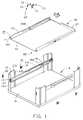
- FIG. 1is an exploded, isometric view of a server rack in accordance with a preferred embodiment, including a base and a bracket;
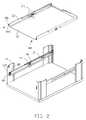
- FIG. 2is a partially assembled view of the server rack of FIG. 1 ;
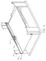
- FIG. 3is an enlarged view of part III in FIG. 1 ;
- FIG. 4is an enlarged view of part IV in FIG. 1 ;
- FIG. 5is a partially assembled view of the server rack of FIG. 1 with the bracket in place in the server rack but extended;
- FIG. 6is an assembled view of the server rack of FIG. 1 with part of the bracket being removed;
- FIG. 7is an enlarged view of part VII in FIG. 6 ;
- FIG. 8is an assembled view of a server rack in accordance with another preferred embodiment.
- a server rack for carrying electronic devicesincludes a base 10 and a receiving bracket 50 .
- the base 10includes a rectangular plate 11 .
- a generally L-shaped stand 13perpendicularly protrudes up from each of the four corners of the plate 11 .
- Each stand 13includes a first sidewall 131 in alignment with a long side of the rectangular plate 11 and a second sidewall 133 perpendicular to the first sidewall 131 and in alignment with a short side of the rectangular plate 11 .
- a flange 135extends inward over the plate 11 from an edge of the first sidewall 135 .
- a guiding rail 15is secured between the second sidewalls of every two stands 13 aligned along the long side of the plate 11 via a pair of fastening members 20 aligned in a vertical direction.
- a securing hole 137is defined between the fastening members 20 in the second sidewall 133 of each of two stands 13 which are aligned along a short side of the plate 11 .
- Each guiding rail 15is generally L-shaped, including a sidewall 151 perpendicular to the plate 11 and abutting against an edge of the flange 135 , and a supporting plate 153 parallel to the plate 11 for supporting the receiving bracket 50 .
- a pair of limiting members 30is respectively secured to each guiding rail 15 at a front end portion and a middle portion thereof. Each limiting member 30 defines a horizontal guiding slot 31 parallel to the supporting plate 153 of the rail 15 .
- the receiving bracket 50includes a bottom wall 51 , a pair of sidewalls 53 perpendicular thereto, and a rear wall 57 perpendicular to the bottom wall 51 and the pair of sidewalls 53 .
- a fixing tab 55extends laterally from a front end of each sidewall 53 .
- a securing hole 551is defined in each fixing tab 55 corresponding to the securing slots 137 respectively.
- a U-shaped slot 535 having a rectangular portion and a pair of thin portionsis defined in a middle portion of each sidewall 53 corresponding to the limiting members 30 at the middle portions of the guiding rails 15 .
- a long thin elastic member 60is secured at the middle portion of each sidewall 53 in parallel with the bottom wall 51 .
- the elastic members 60have a fixed end and a free end.
- a pair of opposite sliding portions 61is bent laterally toward the sidewall 53 of the bracket 30 respectively from an upper edge and a lower edge of each elastic member 60 adjacent to the free end.
- the sliding portions 61extend through the thin portions of the U-shaped slots 535 .
- a tab 63is folded in toward the receiving bracket 50 from the free end of each elastic member 60 and exposed at the rectangular portion of the U-shaped slot 535 , to be available for accessing by a user from an outside of the receiving bracket 50 .
- Each of the elastic members 60is mounted on a folded fixing member 70 .
- the fixing member 70includes a first sidewall 71 parallel to the elastic member 60 and abutting against the fixed end thereof, and a second sidewall 73 connected in parallel with the first sidewall 71 .
- the first sidewall 71is secured to the sidewall 53 of the receiving bracket.
- a pair of flanges 75extending in from bottom and up edges of the second sidewall 73 .
- One of the flanges 75 extending from the bottom edge of the second sidewall 73is secured on the bottom wall 51 of the receiving bracket 50 .
- the receiving bracket 50abuts against edges of the front stands 133 and slides in along the supporting plates 153 of the guiding rails 15 from a front end of the base 10 .
- the sliding portions 61 of the elastic members 60move close to the second sidewalls 133 of the stands 13 and are blocked thereby, the free ends of the elastic members 60 are pressed inward from the rectangular portion of the U-shaped slots 535 in a lateral direction, and the sliding portions 61 retract into the receiving bracket 50 to allow the receiving bracket 50 to move further in along the guiding rails 15 . Then, the receiving bracket 50 is pushed to move further toward a rear end of the base 10 .
- the sliding portions 61 of the elastic members 60slide through the guiding slots 31 of the limiting members 30 at the front end portion of the guiding rails 15 .
- the rear wall 57 of the receiving bracket 50abuts against inner sides of the second sidewalls 133 of the rear stands 13 .
- the upper sliding portion 61 of each elastic member 60is received in the corresponding guiding slot 31 of one of the limiting members 30 at the middle portion of the guiding rails 15 , and the lower sliding portion 61 of each elastic member 60 is blocked by a bottom edge of the corresponding limiting member 30 .
- a pair of fasteners 80is received in the corresponding securing holes 551 and 137 of the receiving bracket 50 and the base 10 to secure the receiving bracket 50 to the base 10 .
- the elastic members 60engage with the limiting members 30 to prevent the receiving bracket 50 from shaking in the base during transport of the server rack.
- the fasteners 80are released first.
- the receiving bracket 50is manually pulled toward front end of the base 10 by a user, which causes the sliding portions 61 of the elastic members 60 to move out from the limiting members 30 at the middle portions of the guiding rails 15 with the receiving bracket 50 .
- the sliding portions 61 of the elastic members 60reach the second sidewalls 133 of the front stands 13 , they are blocked by the second sidewalls 133 , so that the receiving bracket 50 cannot be pulled out from the base 10 further.
- the sliding portions 61are engaged in the guiding slots 31 of the limiting members 30 at the front end portion of the guiding rails 15 , and the receiving bracket 50 is stably positioned at the front end of the base 10 .
- the usercan free hands to push the tabs 63 of the elastic members 60 inward, thus releasing the receiving bracket 50 for further removed from the base 10 .
- FIG. 8a server rack in accordance with another preferred embodiment is shown.
- the server rack of FIG. 8is similar to that of the preceding embodiment except the limiting members 30 a .
- a limiting member 30 ais secured to each guiding rail 15 .
- Each limiting member 30 aextends from the front end portion to the middle portion of each guiding rail 15 .
- a through slot 31 ais defined in the limiting member 30 a in a direction along the sliding direction of the guiding rail 15 .
- the slot 31 ais long enough to ensure the sliding portions 61 of each elastic member 60 to engage therein when the receiving bracket 50 is assembled in the base 10 .
Landscapes
- Engineering & Computer Science (AREA)
- Computer Hardware Design (AREA)
- General Engineering & Computer Science (AREA)
- Microelectronics & Electronic Packaging (AREA)
- Drawers Of Furniture (AREA)
- Warehouses Or Storage Devices (AREA)
Abstract
Description
Claims (10)
Applications Claiming Priority (3)
| Application Number | Priority Date | Filing Date | Title |
|---|---|---|---|
| CNU2007202001339UCN201025521Y (en) | 2007-03-09 | 2007-03-09 | server rack |
| CN200720200133 | 2007-03-09 | ||
| CN200720200133.9 | 2007-03-09 |
Publications (2)
| Publication Number | Publication Date |
|---|---|
| US20080217497A1 US20080217497A1 (en) | 2008-09-11 |
| US7823994B2true US7823994B2 (en) | 2010-11-02 |
Family
ID=39099380
Family Applications (1)
| Application Number | Title | Priority Date | Filing Date |
|---|---|---|---|
| US11/750,348Expired - Fee RelatedUS7823994B2 (en) | 2007-03-09 | 2007-05-18 | Server rack |
Country Status (2)
| Country | Link |
|---|---|
| US (1) | US7823994B2 (en) |
| CN (1) | CN201025521Y (en) |
Cited By (9)
| Publication number | Priority date | Publication date | Assignee | Title |
|---|---|---|---|---|
| US20120161599A1 (en)* | 2010-12-24 | 2012-06-28 | Hon Hai Precision Industry Co., Ltd. | Server holder |
| US20140265793A1 (en)* | 2013-03-15 | 2014-09-18 | Silicon Graphics International Corp. | Bidirectional slide rail |
| US20150122759A1 (en)* | 2013-11-05 | 2015-05-07 | Cisco Technology, Inc. | Rack mounting kit for telecommunications equipment and rack cross brace |
| US9098249B2 (en) | 2013-03-13 | 2015-08-04 | Rpx Corporation | Toolless hot swappable storage module |
| US9161625B2 (en) | 2013-11-08 | 2015-10-20 | King Slide Works Co., Ltd. | Slide rail assembly |
| US9699935B1 (en)* | 2015-11-03 | 2017-07-04 | VCE IP Holding Company LLC | Equipment cradles, rack-mounted equipment systems, and related methods |
| US20170234573A1 (en)* | 2016-02-16 | 2017-08-17 | Microsoft Technology Licensing, Llc | Baffle for directing air flow in a rack |
| US10356931B1 (en)* | 2017-05-26 | 2019-07-16 | King Slide Works Co., Ltd. | Rack mounting system |
| US12363850B2 (en)* | 2023-02-17 | 2025-07-15 | Dell Products L.P. | Tray with translation features supporting on-rack service |
Families Citing this family (17)
| Publication number | Priority date | Publication date | Assignee | Title |
|---|---|---|---|---|
| CN101646326B (en)* | 2008-08-08 | 2012-05-02 | 英业达股份有限公司 | Rail structure |
| TWM352709U (en)* | 2008-10-02 | 2009-03-11 | Alpha Networks Inc | Fixing structure for network device |
| CN101719005B (en)* | 2008-10-09 | 2012-05-16 | 英业达股份有限公司 | Rail structure |
| CN102802368B (en)* | 2011-05-24 | 2016-06-29 | 鸿富锦精密工业(深圳)有限公司 | Machine box for server and server system |
| CN102958316A (en)* | 2011-08-30 | 2013-03-06 | 鸿富锦精密工业(深圳)有限公司 | Sliding type bearing assembly |
| TW201442671A (en)* | 2013-05-14 | 2014-11-16 | Hon Hai Prec Ind Co Ltd | Slide rail assembly |
| CN105425919B (en)* | 2015-12-17 | 2019-04-16 | 英业达科技有限公司 | A kind of server system and its position-limit mechanism of application |
| US10485132B2 (en)* | 2016-05-27 | 2019-11-19 | Hewlett Packard Enterprise Development Lp | Rail kits |
| TWI616162B (en)* | 2016-06-16 | 2018-03-01 | 川湖科技股份有限公司 | Slide rail assembly for use in a rack system |
| US9681574B1 (en)* | 2016-08-18 | 2017-06-13 | Aic Inc. | Chassis self-unlock mechanism |
| TWI601473B (en)* | 2016-10-13 | 2017-10-01 | 川湖科技股份有限公司 | Slide rail assembly |
| CN110505781B (en)* | 2018-05-18 | 2021-01-29 | 鸿富锦精密电子(天津)有限公司 | Base, plug connector fixing device adopting base and plug connector module |
| CN110345891A (en)* | 2019-06-28 | 2019-10-18 | 苏州浪潮智能科技有限公司 | A kind of measuring fixture and method for measurement |
| CN110602916B (en)* | 2019-09-26 | 2020-12-22 | 中国五冶集团有限公司 | Standard rack with nonstandard equipment fixing frame |
| US11574656B2 (en)* | 2020-02-13 | 2023-02-07 | International Business Machines Corporation | Automated tape library deep slot protection |
| CN111367378A (en)* | 2020-03-19 | 2020-07-03 | 英业达科技有限公司 | Servo device |
| CN112987885B (en)* | 2021-03-02 | 2023-03-14 | 英业达科技有限公司 | Server cabinet |
Citations (13)
| Publication number | Priority date | Publication date | Assignee | Title |
|---|---|---|---|---|
| US3133768A (en)* | 1960-01-11 | 1964-05-19 | Markline Electronic Products I | Extensible chassis slide |
| US5085523A (en)* | 1989-08-07 | 1992-02-04 | General Devices Co., Inc. | Slide release mechanism |
| US5626406A (en)* | 1995-02-02 | 1997-05-06 | Glenayre Electronics, Inc. | Integrated chassis slide assembly |
| US6021909A (en)* | 1998-11-13 | 2000-02-08 | Hewlett-Packard Company | Equipment enclosure rack support rail system |
| US6220456B1 (en)* | 2000-04-19 | 2001-04-24 | Dell Products, L.P. | Method and apparatus for supporting a computer chassis |
| US20010035704A1 (en)* | 2000-04-14 | 2001-11-01 | Dierbeck Bruce E. | Ball bearing slide assembly |
| US6497465B1 (en)* | 2000-09-21 | 2002-12-24 | International Business Machines Corporation | Anti-tilt mechanism for a drawer assembly |
| US6588866B2 (en)* | 2001-04-27 | 2003-07-08 | Intel Corporation | Slide rail attachment |
| US6619766B1 (en)* | 1999-10-12 | 2003-09-16 | Gateway, Inc. | Device mounting and retention assembly |
| US20040227441A1 (en)* | 2003-05-14 | 2004-11-18 | Yu-Jiun Wang | Rail assembly for attaching server to cabinet |
| US20050162836A1 (en)* | 2004-01-23 | 2005-07-28 | James Briggs | Modular UPS |
| US7405926B2 (en)* | 2005-04-18 | 2008-07-29 | Aten International Co., Ltd. | Sliding flat panel display and keyboard module |
| US7753460B2 (en)* | 2006-06-23 | 2010-07-13 | Hong Fu Jin Precision Industry (Shenzhen) Co., Ltd. | Multi-section slide assembly |
- 2007
- 2007-03-09CNCNU2007202001339Upatent/CN201025521Y/ennot_activeExpired - Fee Related
- 2007-05-18USUS11/750,348patent/US7823994B2/ennot_activeExpired - Fee Related
Patent Citations (13)
| Publication number | Priority date | Publication date | Assignee | Title |
|---|---|---|---|---|
| US3133768A (en)* | 1960-01-11 | 1964-05-19 | Markline Electronic Products I | Extensible chassis slide |
| US5085523A (en)* | 1989-08-07 | 1992-02-04 | General Devices Co., Inc. | Slide release mechanism |
| US5626406A (en)* | 1995-02-02 | 1997-05-06 | Glenayre Electronics, Inc. | Integrated chassis slide assembly |
| US6021909A (en)* | 1998-11-13 | 2000-02-08 | Hewlett-Packard Company | Equipment enclosure rack support rail system |
| US6619766B1 (en)* | 1999-10-12 | 2003-09-16 | Gateway, Inc. | Device mounting and retention assembly |
| US20010035704A1 (en)* | 2000-04-14 | 2001-11-01 | Dierbeck Bruce E. | Ball bearing slide assembly |
| US6220456B1 (en)* | 2000-04-19 | 2001-04-24 | Dell Products, L.P. | Method and apparatus for supporting a computer chassis |
| US6497465B1 (en)* | 2000-09-21 | 2002-12-24 | International Business Machines Corporation | Anti-tilt mechanism for a drawer assembly |
| US6588866B2 (en)* | 2001-04-27 | 2003-07-08 | Intel Corporation | Slide rail attachment |
| US20040227441A1 (en)* | 2003-05-14 | 2004-11-18 | Yu-Jiun Wang | Rail assembly for attaching server to cabinet |
| US20050162836A1 (en)* | 2004-01-23 | 2005-07-28 | James Briggs | Modular UPS |
| US7405926B2 (en)* | 2005-04-18 | 2008-07-29 | Aten International Co., Ltd. | Sliding flat panel display and keyboard module |
| US7753460B2 (en)* | 2006-06-23 | 2010-07-13 | Hong Fu Jin Precision Industry (Shenzhen) Co., Ltd. | Multi-section slide assembly |
Cited By (10)
| Publication number | Priority date | Publication date | Assignee | Title |
|---|---|---|---|---|
| US20120161599A1 (en)* | 2010-12-24 | 2012-06-28 | Hon Hai Precision Industry Co., Ltd. | Server holder |
| US9098249B2 (en) | 2013-03-13 | 2015-08-04 | Rpx Corporation | Toolless hot swappable storage module |
| US20140265793A1 (en)* | 2013-03-15 | 2014-09-18 | Silicon Graphics International Corp. | Bidirectional slide rail |
| US20150122759A1 (en)* | 2013-11-05 | 2015-05-07 | Cisco Technology, Inc. | Rack mounting kit for telecommunications equipment and rack cross brace |
| US9635937B2 (en)* | 2013-11-05 | 2017-05-02 | Cisco Technology, Inc. | Rack mounting kit for telecommunications equipment and rack cross brace |
| US9161625B2 (en) | 2013-11-08 | 2015-10-20 | King Slide Works Co., Ltd. | Slide rail assembly |
| US9699935B1 (en)* | 2015-11-03 | 2017-07-04 | VCE IP Holding Company LLC | Equipment cradles, rack-mounted equipment systems, and related methods |
| US20170234573A1 (en)* | 2016-02-16 | 2017-08-17 | Microsoft Technology Licensing, Llc | Baffle for directing air flow in a rack |
| US10356931B1 (en)* | 2017-05-26 | 2019-07-16 | King Slide Works Co., Ltd. | Rack mounting system |
| US12363850B2 (en)* | 2023-02-17 | 2025-07-15 | Dell Products L.P. | Tray with translation features supporting on-rack service |
Also Published As
| Publication number | Publication date |
|---|---|
| CN201025521Y (en) | 2008-02-20 |
| US20080217497A1 (en) | 2008-09-11 |
Similar Documents
| Publication | Publication Date | Title |
|---|---|---|
| US7823994B2 (en) | Server rack | |
| US8356718B2 (en) | Server rack assembly | |
| US8770681B2 (en) | Rack with lockable tray | |
| US20080303390A1 (en) | Server rack assembly | |
| US8328300B2 (en) | Mounting apparatus for slide rail | |
| US7815266B2 (en) | Cabinet for electronic devices | |
| US20090315434A1 (en) | Mounting apparatus for slide rail | |
| US20110068243A1 (en) | Adjustable apparatus | |
| US20120013092A1 (en) | Rack for electronic apparatus | |
| US20100172086A1 (en) | Mounting apparatus for disk drive | |
| US20120012543A1 (en) | Server rack assembly | |
| US7269020B2 (en) | Bezel mounting device | |
| US7679900B2 (en) | Computer enclosure | |
| US9172153B2 (en) | Grounding member and mounting apparatus for hard disk drive | |
| US7374259B2 (en) | Detachable case assembly for computer server | |
| US8238097B2 (en) | Computer system | |
| US8336719B2 (en) | Rack frame | |
| US8248811B2 (en) | Server enclosure and server enclosure assembly | |
| US20100264787A1 (en) | Computer system with circuit board | |
| US20030080654A1 (en) | Computer enclosure with drive bracket | |
| US20110221314A1 (en) | Cabinet rack and rack mount holder | |
| US8066535B2 (en) | Mounting apparatus for electronic device | |
| US8075070B2 (en) | Computer enclosure with power supply chassis | |
| US9148976B2 (en) | Rail mounting mechanism | |
| US20140166535A1 (en) | Enclosure with backplane |
Legal Events
| Date | Code | Title | Description |
|---|---|---|---|
| AS | Assignment | Owner name:HON HAI PRECISION INDUSTRY CO., LTD., TAIWAN Free format text:ASSIGNMENT OF ASSIGNORS INTEREST;ASSIGNORS:YANG, CHIEH;CHANG, HUNG-CHIEH;CHEN, LI-PING;REEL/FRAME:019311/0743 Effective date:20070409 | |
| FPAY | Fee payment | Year of fee payment:4 | |
| AS | Assignment | Owner name:CLOUD NETWORK TECHNOLOGY SINGAPORE PTE. LTD., SINGAPORE Free format text:ASSIGNMENT OF ASSIGNORS INTEREST;ASSIGNOR:HON HAI PRECISION INDUSTRY CO., LTD.;REEL/FRAME:045281/0269 Effective date:20180112 Owner name:CLOUD NETWORK TECHNOLOGY SINGAPORE PTE. LTD., SING Free format text:ASSIGNMENT OF ASSIGNORS INTEREST;ASSIGNOR:HON HAI PRECISION INDUSTRY CO., LTD.;REEL/FRAME:045281/0269 Effective date:20180112 | |
| FEPP | Fee payment procedure | Free format text:MAINTENANCE FEE REMINDER MAILED (ORIGINAL EVENT CODE: REM.) | |
| LAPS | Lapse for failure to pay maintenance fees | Free format text:PATENT EXPIRED FOR FAILURE TO PAY MAINTENANCE FEES (ORIGINAL EVENT CODE: EXP.); ENTITY STATUS OF PATENT OWNER: LARGE ENTITY | |
| STCH | Information on status: patent discontinuation | Free format text:PATENT EXPIRED DUE TO NONPAYMENT OF MAINTENANCE FEES UNDER 37 CFR 1.362 | |
| FP | Lapsed due to failure to pay maintenance fee | Effective date:20181102 |