US7822995B2 - Apparatus and method for protecting diagnostic ports of secure devices - Google Patents
Apparatus and method for protecting diagnostic ports of secure devicesDownload PDFInfo
- Publication number
- US7822995B2 US7822995B2US11/070,911US7091105AUS7822995B2US 7822995 B2US7822995 B2US 7822995B2US 7091105 AUS7091105 AUS 7091105AUS 7822995 B2US7822995 B2US 7822995B2
- Authority
- US
- United States
- Prior art keywords
- switching circuit
- electronic system
- diagnostic port
- switch
- contents
- Prior art date
- Legal status (The legal status is an assumption and is not a legal conclusion. Google has not performed a legal analysis and makes no representation as to the accuracy of the status listed.)
- Expired - Fee Related, expires
Links
Images


Classifications
- G—PHYSICS
- G06—COMPUTING OR CALCULATING; COUNTING
- G06F—ELECTRIC DIGITAL DATA PROCESSING
- G06F21/00—Security arrangements for protecting computers, components thereof, programs or data against unauthorised activity
- G06F21/60—Protecting data
- G06F21/62—Protecting access to data via a platform, e.g. using keys or access control rules
- G—PHYSICS
- G06—COMPUTING OR CALCULATING; COUNTING
- G06F—ELECTRIC DIGITAL DATA PROCESSING
- G06F11/00—Error detection; Error correction; Monitoring
- G06F11/36—Prevention of errors by analysis, debugging or testing of software
- G06F11/362—Debugging of software
- G06F11/3648—Debugging of software using additional hardware
- G06F11/3656—Debugging of software using additional hardware using a specific debug interface
- G—PHYSICS
- G06—COMPUTING OR CALCULATING; COUNTING
- G06F—ELECTRIC DIGITAL DATA PROCESSING
- G06F21/00—Security arrangements for protecting computers, components thereof, programs or data against unauthorised activity
- G06F21/70—Protecting specific internal or peripheral components, in which the protection of a component leads to protection of the entire computer
- G06F21/71—Protecting specific internal or peripheral components, in which the protection of a component leads to protection of the entire computer to assure secure computing or processing of information
- G—PHYSICS
- G06—COMPUTING OR CALCULATING; COUNTING
- G06F—ELECTRIC DIGITAL DATA PROCESSING
- G06F2221/00—Indexing scheme relating to security arrangements for protecting computers, components thereof, programs or data against unauthorised activity
- G06F2221/21—Indexing scheme relating to G06F21/00 and subgroups addressing additional information or applications relating to security arrangements for protecting computers, components thereof, programs or data against unauthorised activity
- G06F2221/2105—Dual mode as a secondary aspect
- G—PHYSICS
- G06—COMPUTING OR CALCULATING; COUNTING
- G06F—ELECTRIC DIGITAL DATA PROCESSING
- G06F2221/00—Indexing scheme relating to security arrangements for protecting computers, components thereof, programs or data against unauthorised activity
- G06F2221/21—Indexing scheme relating to G06F21/00 and subgroups addressing additional information or applications relating to security arrangements for protecting computers, components thereof, programs or data against unauthorised activity
- G06F2221/2143—Clearing memory, e.g. to prevent the data from being stolen
Definitions
- This inventionrelates to electronic devices and more particularly to the control of access to electronic devices.
- Diagnostic portssuch as a JTAG (Joint Test Action Group) port, are provided on microprocessor-controlled systems to permit diagnosing of hardware or software problems. Standard, off-the-shelf equipment can be connected to a system through these ports to directly control the connected microprocessor, memory, and/or peripheral ports, for performing CPU commands, tracing program execution, stopping at breakpoints, etc.
- Such diagnostic portsare invaluable tools for searching for the cause of unexpected behavior of a system. Therefore, these ports should be built into the system and not permanently disabled or removed after manufacturing.
- diagnostic portssupport the diagnosis of problems in microprocessor-controlled systems, they are also a source of vulnerability. An adversary can connect a debugger to the port and access all the secrets on the security system. Therefore, the use of these ports must be controlled. Methods and devices which protect sensitive data by making it inaccessible (either ab initio or by active erasure) when access to a diagnostic port is attempted have been described.
- Hardware or software authentication mechanismssuch as passwords, tokens, biometrics etc., could also be used.
- Special software (or firmware) versionscan be authenticated and loaded to open up the ports.
- Switches or jumperscan be used to activate special resident firmware versions, which open up the ports.
- the main drawback of these methodsis that activation of the diagnostic ports requires functional authentication, so problems affecting that function cannot be diagnosed.
- This inventionprovides a system having a diagnostic port, wherein access to secure components of the system is prevented.
- An electronic system constructed in accordance with this inventioncomprises a processor, a diagnostic port, and a switching circuit including a switch connected between the diagnostic port and the processor, for enabling and disabling the diagnostic port and for restricting access to contents of the electronic system prior to enabling the diagnostic port.
- the inventionencompasses a method of operating an electronic system.
- the methodcomprises: providing a switching circuit including a switch connected between a diagnostic port and a processor, for enabling and disabling the diagnostic port, determining the operational status of the switch, and using the switching circuit to restrict access to contents of the electronic system in response to the operational status of the switch prior to enabling the diagnostic port.
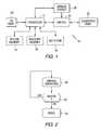
- FIG. 1is a block diagram of a microprocessor system that includes a diagnostic port in accordance with this invention.
- FIGS. 2 and 3are flow diagrams that illustrate the operation of the invention.
- FIG. 1is a block diagram of a microprocessor system 10 that includes a diagnostic port in accordance with this invention.
- the systemincludes a processor 12 , a secure memory 14 , an insecure memory 16 , and a key store 18 , which can be a non-volatile memory.
- the secure memory and key storeare not accessible from outside of the system.
- At least one input/output (I/O) port 20is provided so that the processor can operate in conjunction with external devices.
- a diagnostic port 22is provided to connect diagnostic equipment to the system.
- a switching circuit 24includes a switch that is used to connect or disconnect the diagnostic port and the processor.
- the switchcan be mechanical, electronic, magnetic, capacitive, photosensitive, or any other type known.
- An optional sensor circuit 26can be provided to control the operation of the switch.
- the switching circuitis also connected to the key store 18 and a master key store. The switching circuit can erase the secure memory 14 as described below.
- the processoris connected to the secure memory, and optionally, to insecure memory.
- the processorcommunicates to the outside world via an I/O port.
- the diagnostic portis coupled to the processor through the switch.
- the diagnostic portcan be used to request execution of processor commands, read and/or write to memory, set breakpoints, and trace information movement in the processor system.
- the optional sensor circuitis a hardware device that can be implemented in various ways. It detects if a connector is attached to the diagnostic port, and activates the switch in the switching circuit, which will in turn activate the diagnostic port following the implementation of several security features described below. By using the sensor circuit, no extra action is needed to enable the diagnostic port. Only a suitable cable has to be attached.
- a secret root keyis stored in the master key store.
- the root keycan optionally be used to encrypt (one or more) user key(s), that are stored only in encrypted form in the key store 18 , which may be a nonvolatile memory of the system (such as a disc, Flash, ROM, etc.).
- the user keys, if there are any, or the root keyis used to encrypt all the confidential information stored in the system.
- the secret root keyis not accessible from outside the microprocessor system.
- the systemalso includes firmware having an unchangeable, or persistent, part (ROM code) and a changeable downloadable part.
- ROM codeunchangeable, or persistent, part
- the unchangeable part of the system firmwarecan be used to perform an integrity and authenticity check on the rest of the firmware (downloadable) and the nonvolatile storage device.
- the firmware codecan be stored in a nonvolatile part of the insecure memory 16 , or in a separate nonvolatile program storage, such as a disc, FLASH memory, EPROM memory, or similar device.
- FIGS. 2 and 3are flow diagrams that illustrate the operation of the invention.
- the functions described in the figuresare performed in hardware, allowing the diagnosis (debugging) of the whole firmware code and the proper operation of the microprocessor.
- FIG. 2illustrates the operation of the system when the switch is activated while the system is operating.
- the status of the switchis checked (block 32 ).
- the activation of the switchcan cause an immediate hardware action by starting an electronic circuit, which can be a part of the switching circuit 24 , very much like an interrupt initiates actions in a microprocessor.
- Another alternativeis that the hardware periodically checks the status of the switch and performs its actions accordingly. This check of the switch would be performed frequently enough, such that a human operator notices no disturbing delay (10 . . . 100 ms).
- the switchis off, normal operation continues. If the switch changes position from off to on, the system is reset (block 34 ). The reset occurs entirely under hardware control.
- the microprocessorcan be reset by the switching circuit applying an appropriate voltage to the microprocessor reset pin. Other components of the system are similarly reset with appropriate reset signals, applied to their reset request lines, which are customarily provided in electronic circuits.
- the switching circuitwould also mask the secret root key, which means that any access to the root key is temporarily diverted to access another, predetermined value. The root key itself is not changed. It only becomes hidden by being replaced during the time that diagnostic port is open.
- each electronic circuitcan produce a logic “done” signal.
- the switching circuitwould then perform AND operation of these “reset done” and “key masked” signals, and when the result is true, the switching circuit would close the switch to activate the diagnostic port (e.g. by operating a simple electronic switch to connect the diagnostic port pins to the internal diagnostic bus).
- the systemcould be reset by another means, such as cutting the power, and the status of the switch would be ignored until the next boot-up, when the memory erase and the key masking occurs.
- Resetting of the systemcan include the steps of erasing the contents of the memory, or prohibiting the changing of some nonvolatile memory in the system, etc.
- the diagnostic portremains disabled until the memory is cleared and the keys are masked. Thus the information contained in these components would not be accessible from outside of the system. Only volatile memory would be erased, with the same effects as a loss of power. Unfinished transactions have to be unrolled or finished when the system gets back to normal operation. The content of the erased volatile memory cannot be recovered, only recreated by the proper software under normal (non-diagnostic) operations.
- FIG. 3illustrates the operation of the system at start-up.
- the status of the switchis checked (block 38 ). If the switch is not activated, the diagnostic port is disabled (block 40 ) and normal operation of the system proceeds (block 42 ). In this condition, the status of the switch is repeatedly checked as shown in FIG. 2 .
- the switchis activated at start-up, sensitive memory is cleared (block 44 ), the root key is masked or blocked (block 46 ), and the diagnostic port is enabled (block 48 ). After these steps, the system can be limited to some restricted operations and system access to the root key results in some predetermined value, such as all 0's (block 50 ).
- the root key and the masked root keyare accessible by the microprocessor via an alternating switch (multiplexer) in the switching circuit (see FIG. 1 .). When the root key is masked, a hardware signal selects another set of inputs of the multiplexer. These input lines can lead to internal read-only memory cells or direct (hard wired) connections to the ground (logic 0) or the supply voltage (logic 1).
- the root keyis needed to encrypt and decrypt confidential information in the system. Since the root key is blocked, no secrets can be decrypted. Even if a new, unauthorized firmware were to be downloaded, the next time the system boots up in a non-diagnostic mode, the unchangeable part of the system firmware (ROM code) can be used to detect the rogue firmware and halt operation of the system.
- ROM codeunchangeable part of the system firmware
- tamper evidencecan be provided, such as an extra physical detection mechanism (glue, paint, tape, plastic connector, oxidizer, snap), to indicate that the diagnostic port has been activated at least once.
- Further specific mechanisms used in conjunction with the sensor circuit to strengthen tamper-evidencemay include employing a jumper connection which completes a circuit. The completion of the circuit prevents the diagnostic port from being activated.
- the jumpercan act in conjunction with, or effectively be a part of, the switch. When the jumper is removed, the diagnostic port can be activated by way of the sensor circuit.
- the jumpercan be sealed or physically connected in such a way that its removal is evident, i.e. replacing it undetectably is difficult.
- An advantage of this techniqueis the ability to decide, flexibly and simply, whether diagnosis will be enabled while simultaneously ensuring that any attempt at opening a diagnostic port will be detectable.
- no secret informationsuch as user data, firmware code, or cryptographic keys
- the switchcan be a low cost and low complexity device, that provides reliable operation, so the loss of its diagnoseability can be accepted. Access to the diagnostic port can be easily verified.
- the microprocessor codecan be diagnosed from the very first instruction, that is, the process of boot-up is included in the diagnoseable functions of the system.
- the boot-up processincludes, as is usual in microprocessors, activating a circuit to clear the internal registers of the microprocessor and to set the instruction pointer of the microprocessor to a predetermined address in the read-only program memory, and providing an electronic signal causing the microprocessor start performing commands found in the program memory.
- Port activationwould not involve any firmware action (thereby enabling debugging of the firmware).
- Real code used in the fieldnot special versions, would be available for diagnosis.
- Hardware functionscan be accessible, that is, the hardware in the diagnostic mode accepts the same requests as in normal mode and returns valid results. If the system includes (optional) restricted operations (like overwriting some nonvolatile memory areas), the restricted operations will not affect hardware accessibility. Non-security functions (such as code or hardware) would not be affected.
Landscapes
- Engineering & Computer Science (AREA)
- Theoretical Computer Science (AREA)
- Computer Hardware Design (AREA)
- Physics & Mathematics (AREA)
- General Engineering & Computer Science (AREA)
- General Physics & Mathematics (AREA)
- Software Systems (AREA)
- Computer Security & Cryptography (AREA)
- Mathematical Physics (AREA)
- Health & Medical Sciences (AREA)
- Bioethics (AREA)
- General Health & Medical Sciences (AREA)
- Quality & Reliability (AREA)
- Storage Device Security (AREA)
Abstract
Description
Claims (13)
Priority Applications (1)
| Application Number | Priority Date | Filing Date | Title |
|---|---|---|---|
| US11/070,911US7822995B2 (en) | 2005-03-03 | 2005-03-03 | Apparatus and method for protecting diagnostic ports of secure devices |
Applications Claiming Priority (1)
| Application Number | Priority Date | Filing Date | Title |
|---|---|---|---|
| US11/070,911US7822995B2 (en) | 2005-03-03 | 2005-03-03 | Apparatus and method for protecting diagnostic ports of secure devices |
Publications (2)
| Publication Number | Publication Date |
|---|---|
| US20060200682A1 US20060200682A1 (en) | 2006-09-07 |
| US7822995B2true US7822995B2 (en) | 2010-10-26 |
Family
ID=36945405
Family Applications (1)
| Application Number | Title | Priority Date | Filing Date |
|---|---|---|---|
| US11/070,911Expired - Fee RelatedUS7822995B2 (en) | 2005-03-03 | 2005-03-03 | Apparatus and method for protecting diagnostic ports of secure devices |
Country Status (1)
| Country | Link |
|---|---|
| US (1) | US7822995B2 (en) |
Cited By (6)
| Publication number | Priority date | Publication date | Assignee | Title |
|---|---|---|---|---|
| US20080229092A1 (en)* | 2006-06-09 | 2008-09-18 | International Business Machines Corporation | Secure Boot Across a Plurality of Processors |
| US20090055640A1 (en)* | 2006-06-09 | 2009-02-26 | International Business Machines Corporation | Masking a Hardware Boot Sequence |
| US20090327680A1 (en)* | 2006-06-09 | 2009-12-31 | International Business Machines Corporation | Selecting a Random Processor to Boot on a Multiprocessor System |
| US20100146302A1 (en)* | 2006-09-14 | 2010-06-10 | Austriamicrosystems Ag | Microcontroller and Method for Starting an Application Program on a Microcontroller |
| US20100303239A1 (en)* | 2009-05-27 | 2010-12-02 | Fujitsu Limited | Method and apparatus for protecting root key in control system |
| US20130031419A1 (en)* | 2011-07-28 | 2013-01-31 | International Business Machines Corporation | Collecting Debug Data in a Secure Chip Implementation |
Families Citing this family (8)
| Publication number | Priority date | Publication date | Assignee | Title |
|---|---|---|---|---|
| US7363564B2 (en)* | 2005-07-15 | 2008-04-22 | Seagate Technology Llc | Method and apparatus for securing communications ports in an electronic device |
| US20090172639A1 (en)* | 2007-12-27 | 2009-07-02 | Mahesh Natu | Firmware integrity verification |
| US9141776B2 (en)* | 2008-04-30 | 2015-09-22 | Telefonaktiebolaget Lm Ericsson (Publ) | Method and apparatus for secure hardware analysis |
| US8694761B2 (en)* | 2008-12-31 | 2014-04-08 | Vincent Zimmer | System and method to secure boot both UEFI and legacy option ROM's with common policy engine |
| GB2484458A (en)* | 2010-10-04 | 2012-04-18 | Thorn Security | Commissioning detector units of an alarm system by means of a remote infrared based communication tool |
| CN104365186B (en)* | 2012-05-04 | 2017-08-22 | 司亚乐无线通讯股份有限公司 | It is encapsulated in the UICC in the printed circuit board (PCB) of wireless terminal |
| US11416625B2 (en)* | 2018-01-31 | 2022-08-16 | Cryptography Research, Inc. | Protecting cryptographic keys stored in non-volatile memory |
| TWI713957B (en)* | 2018-12-22 | 2020-12-21 | 新唐科技股份有限公司 | Electronic apparatus with unlocking debugging function |
Citations (15)
| Publication number | Priority date | Publication date | Assignee | Title |
|---|---|---|---|---|
| US5467396A (en) | 1993-10-27 | 1995-11-14 | The Titan Corporation | Tamper-proof data storage |
| US5469557A (en) | 1993-03-05 | 1995-11-21 | Microchip Technology Incorporated | Code protection in microcontroller with EEPROM fuses |
| US5515540A (en) | 1990-08-27 | 1996-05-07 | Dallas Semiconducter Corp. | Microprocessor with single pin for memory wipe |
| US6026293A (en) | 1996-09-05 | 2000-02-15 | Ericsson Inc. | System for preventing electronic memory tampering |
| US6085090A (en)* | 1997-10-20 | 2000-07-04 | Motorola, Inc. | Autonomous interrogatable information and position device |
| US6272637B1 (en) | 1997-04-14 | 2001-08-07 | Dallas Semiconductor Corporation | Systems and methods for protecting access to encrypted information |
| US20020013670A1 (en) | 2000-07-28 | 2002-01-31 | Ouellette Maurice J. | Methods and apparatus for secure programming of an electricity meter |
| US6466048B1 (en)* | 2001-05-23 | 2002-10-15 | Mosaid Technologies, Inc. | Method and apparatus for switchably selecting an integrated circuit operating mode |
| US6475180B2 (en)* | 1992-09-09 | 2002-11-05 | Sims Deltec, Inc. | Drug pump systems and methods |
| US20020174342A1 (en) | 2001-05-15 | 2002-11-21 | International Business Machines Corporation | Method and system for setting a secure computer environment |
| US20030014642A1 (en) | 1999-09-17 | 2003-01-16 | Fingloq Ab | Security arrangement |
| US6633807B2 (en)* | 2000-08-14 | 2003-10-14 | Audi Performance & Racing | Enhanced module chipping system |
| US20030212897A1 (en) | 2001-08-18 | 2003-11-13 | Russell Dickerson | Method and system for maintaining secure semiconductor device areas |
| US20040025027A1 (en) | 2002-07-30 | 2004-02-05 | Eric Balard | Secure protection method for access to protected resources in a processor |
| US20050259814A1 (en)* | 2004-05-24 | 2005-11-24 | Gebotys Catherine H | Table masking for resistance to power analysis attacks |
- 2005
- 2005-03-03USUS11/070,911patent/US7822995B2/ennot_activeExpired - Fee Related
Patent Citations (15)
| Publication number | Priority date | Publication date | Assignee | Title |
|---|---|---|---|---|
| US5515540A (en) | 1990-08-27 | 1996-05-07 | Dallas Semiconducter Corp. | Microprocessor with single pin for memory wipe |
| US6475180B2 (en)* | 1992-09-09 | 2002-11-05 | Sims Deltec, Inc. | Drug pump systems and methods |
| US5469557A (en) | 1993-03-05 | 1995-11-21 | Microchip Technology Incorporated | Code protection in microcontroller with EEPROM fuses |
| US5467396A (en) | 1993-10-27 | 1995-11-14 | The Titan Corporation | Tamper-proof data storage |
| US6026293A (en) | 1996-09-05 | 2000-02-15 | Ericsson Inc. | System for preventing electronic memory tampering |
| US6272637B1 (en) | 1997-04-14 | 2001-08-07 | Dallas Semiconductor Corporation | Systems and methods for protecting access to encrypted information |
| US6085090A (en)* | 1997-10-20 | 2000-07-04 | Motorola, Inc. | Autonomous interrogatable information and position device |
| US20030014642A1 (en) | 1999-09-17 | 2003-01-16 | Fingloq Ab | Security arrangement |
| US20020013670A1 (en) | 2000-07-28 | 2002-01-31 | Ouellette Maurice J. | Methods and apparatus for secure programming of an electricity meter |
| US6633807B2 (en)* | 2000-08-14 | 2003-10-14 | Audi Performance & Racing | Enhanced module chipping system |
| US20020174342A1 (en) | 2001-05-15 | 2002-11-21 | International Business Machines Corporation | Method and system for setting a secure computer environment |
| US6466048B1 (en)* | 2001-05-23 | 2002-10-15 | Mosaid Technologies, Inc. | Method and apparatus for switchably selecting an integrated circuit operating mode |
| US20030212897A1 (en) | 2001-08-18 | 2003-11-13 | Russell Dickerson | Method and system for maintaining secure semiconductor device areas |
| US20040025027A1 (en) | 2002-07-30 | 2004-02-05 | Eric Balard | Secure protection method for access to protected resources in a processor |
| US20050259814A1 (en)* | 2004-05-24 | 2005-11-24 | Gebotys Catherine H | Table masking for resistance to power analysis attacks |
Cited By (12)
| Publication number | Priority date | Publication date | Assignee | Title |
|---|---|---|---|---|
| US20080229092A1 (en)* | 2006-06-09 | 2008-09-18 | International Business Machines Corporation | Secure Boot Across a Plurality of Processors |
| US20090055640A1 (en)* | 2006-06-09 | 2009-02-26 | International Business Machines Corporation | Masking a Hardware Boot Sequence |
| US20090327680A1 (en)* | 2006-06-09 | 2009-12-31 | International Business Machines Corporation | Selecting a Random Processor to Boot on a Multiprocessor System |
| US8037293B2 (en) | 2006-06-09 | 2011-10-11 | International Business Machines Corporation | Selecting a random processor to boot on a multiprocessor system |
| US8046573B2 (en)* | 2006-06-09 | 2011-10-25 | International Business Machines Corporation | Masking a hardware boot sequence |
| US8046574B2 (en) | 2006-06-09 | 2011-10-25 | International Business Machines Corporation | Secure boot across a plurality of processors |
| US20100146302A1 (en)* | 2006-09-14 | 2010-06-10 | Austriamicrosystems Ag | Microcontroller and Method for Starting an Application Program on a Microcontroller |
| US8352753B2 (en)* | 2006-09-14 | 2013-01-08 | Austriamicrosystems Ag | Microcontroller and method for starting an application program on a microcontroller by which unauthorized access to data contained in or processed by the microcontroller is prevented |
| US20100303239A1 (en)* | 2009-05-27 | 2010-12-02 | Fujitsu Limited | Method and apparatus for protecting root key in control system |
| US20130031419A1 (en)* | 2011-07-28 | 2013-01-31 | International Business Machines Corporation | Collecting Debug Data in a Secure Chip Implementation |
| US20130031420A1 (en)* | 2011-07-28 | 2013-01-31 | International Business Machines Corporation | Collecting Debug Data in a Secure Chip Implementation |
| US8843785B2 (en)* | 2011-07-28 | 2014-09-23 | International Business Machines Corporation | Collecting debug data in a secure chip implementation |
Also Published As
| Publication number | Publication date |
|---|---|
| US20060200682A1 (en) | 2006-09-07 |
Similar Documents
| Publication | Publication Date | Title |
|---|---|---|
| JP4260984B2 (en) | Information processing apparatus and information processing method | |
| US7849315B2 (en) | Method for managing operability of on-chip debug capability | |
| USRE47621E1 (en) | Secure transaction microcontroller with secure boot loader | |
| JP5419776B2 (en) | Semiconductor device and data processing method | |
| EP2023248B1 (en) | Data processing device, method, program, integrated circuit, and program generating device | |
| CN101533441B (en) | Apparatus for providing secure execution environment and method for executing secure code thereof | |
| US20060282734A1 (en) | Test access control for secure integrated circuits | |
| US7822995B2 (en) | Apparatus and method for protecting diagnostic ports of secure devices | |
| US7107460B2 (en) | Method and system for securing enablement access to a data security device | |
| CN101241534A (en) | Semiconductor device with encryption part or external interface and content reproduction method | |
| EA012921B1 (en) | Method and device for protecting software from unauthorized use | |
| JP6771523B2 (en) | Memory protection device and method | |
| Bittner et al. | The forgotten threat of voltage glitching: a case study on Nvidia Tegra X2 SoCs | |
| CN111695164A (en) | Electronic device and control method thereof | |
| Khan et al. | Utilizing and extending trusted execution environment in heterogeneous SoCs for a pay-per-device IP licensing scheme | |
| CN101124768A (en) | System and method for using protected non-volatile memory | |
| US20240187231A1 (en) | Forensics Module and Integrated System | |
| KR20170102285A (en) | Security Elements | |
| Zhao et al. | Gracewipe: Secure and Verifiable Deletion under Coercion. | |
| WO2005029272A2 (en) | Method and device for data protection and security in a gaming machine | |
| JP5761880B2 (en) | Automobile | |
| US20150324610A1 (en) | Method for managing software functionalities in a control unit | |
| JP2008071250A (en) | Access control device | |
| JP5603993B2 (en) | Electrical unit and data processing method | |
| US20240193564A1 (en) | Forensics Module and Embedded System |
Legal Events
| Date | Code | Title | Description |
|---|---|---|---|
| AS | Assignment | Owner name:SEAGATE TECHNOLOGY LLC, CALIFORNIA Free format text:ASSIGNMENT OF ASSIGNORS INTEREST;ASSIGNORS:HARS, LASZLO;BEAVER, DONALD ROZINAK;REEL/FRAME:016357/0803;SIGNING DATES FROM 20041101 TO 20050302 Owner name:SEAGATE TECHNOLOGY LLC, CALIFORNIA Free format text:ASSIGNMENT OF ASSIGNORS INTEREST;ASSIGNORS:HARS, LASZLO;BEAVER, DONALD ROZINAK;SIGNING DATES FROM 20041101 TO 20050302;REEL/FRAME:016357/0803 | |
| AS | Assignment | Owner name:WELLS FARGO BANK, NATIONAL ASSOCIATION, AS COLLATERAL AGENT AND SECOND PRIORITY REPRESENTATIVE, CALIFORNIA Free format text:SECURITY AGREEMENT;ASSIGNORS:MAXTOR CORPORATION;SEAGATE TECHNOLOGY LLC;SEAGATE TECHNOLOGY INTERNATIONAL;REEL/FRAME:022757/0017 Effective date:20090507 Owner name:JPMORGAN CHASE BANK, N.A., AS ADMINISTRATIVE AGENT AND FIRST PRIORITY REPRESENTATIVE, NEW YORK Free format text:SECURITY AGREEMENT;ASSIGNORS:MAXTOR CORPORATION;SEAGATE TECHNOLOGY LLC;SEAGATE TECHNOLOGY INTERNATIONAL;REEL/FRAME:022757/0017 Effective date:20090507 Owner name:JPMORGAN CHASE BANK, N.A., AS ADMINISTRATIVE AGENT Free format text:SECURITY AGREEMENT;ASSIGNORS:MAXTOR CORPORATION;SEAGATE TECHNOLOGY LLC;SEAGATE TECHNOLOGY INTERNATIONAL;REEL/FRAME:022757/0017 Effective date:20090507 Owner name:WELLS FARGO BANK, NATIONAL ASSOCIATION, AS COLLATE Free format text:SECURITY AGREEMENT;ASSIGNORS:MAXTOR CORPORATION;SEAGATE TECHNOLOGY LLC;SEAGATE TECHNOLOGY INTERNATIONAL;REEL/FRAME:022757/0017 Effective date:20090507 | |
| STCF | Information on status: patent grant | Free format text:PATENTED CASE | |
| AS | Assignment | Owner name:MAXTOR CORPORATION, CALIFORNIA Free format text:RELEASE;ASSIGNOR:JPMORGAN CHASE BANK, N.A., AS ADMINISTRATIVE AGENT;REEL/FRAME:025662/0001 Effective date:20110114 Owner name:SEAGATE TECHNOLOGY HDD HOLDINGS, CALIFORNIA Free format text:RELEASE;ASSIGNOR:JPMORGAN CHASE BANK, N.A., AS ADMINISTRATIVE AGENT;REEL/FRAME:025662/0001 Effective date:20110114 Owner name:SEAGATE TECHNOLOGY LLC, CALIFORNIA Free format text:RELEASE;ASSIGNOR:JPMORGAN CHASE BANK, N.A., AS ADMINISTRATIVE AGENT;REEL/FRAME:025662/0001 Effective date:20110114 Owner name:SEAGATE TECHNOLOGY INTERNATIONAL, CALIFORNIA Free format text:RELEASE;ASSIGNOR:JPMORGAN CHASE BANK, N.A., AS ADMINISTRATIVE AGENT;REEL/FRAME:025662/0001 Effective date:20110114 | |
| AS | Assignment | Owner name:THE BANK OF NOVA SCOTIA, AS ADMINISTRATIVE AGENT, CANADA Free format text:SECURITY AGREEMENT;ASSIGNOR:SEAGATE TECHNOLOGY LLC;REEL/FRAME:026010/0350 Effective date:20110118 Owner name:THE BANK OF NOVA SCOTIA, AS ADMINISTRATIVE AGENT, Free format text:SECURITY AGREEMENT;ASSIGNOR:SEAGATE TECHNOLOGY LLC;REEL/FRAME:026010/0350 Effective date:20110118 | |
| AS | Assignment | Owner name:SEAGATE TECHNOLOGY US HOLDINGS, INC., CALIFORNIA Free format text:TERMINATION AND RELEASE OF SECURITY INTEREST IN PATENT RIGHTS;ASSIGNOR:WELLS FARGO BANK, NATIONAL ASSOCIATION, AS COLLATERAL AGENT AND SECOND PRIORITY REPRESENTATIVE;REEL/FRAME:030833/0001 Effective date:20130312 Owner name:EVAULT INC. (F/K/A I365 INC.), CALIFORNIA Free format text:TERMINATION AND RELEASE OF SECURITY INTEREST IN PATENT RIGHTS;ASSIGNOR:WELLS FARGO BANK, NATIONAL ASSOCIATION, AS COLLATERAL AGENT AND SECOND PRIORITY REPRESENTATIVE;REEL/FRAME:030833/0001 Effective date:20130312 Owner name:SEAGATE TECHNOLOGY LLC, CALIFORNIA Free format text:TERMINATION AND RELEASE OF SECURITY INTEREST IN PATENT RIGHTS;ASSIGNOR:WELLS FARGO BANK, NATIONAL ASSOCIATION, AS COLLATERAL AGENT AND SECOND PRIORITY REPRESENTATIVE;REEL/FRAME:030833/0001 Effective date:20130312 Owner name:SEAGATE TECHNOLOGY INTERNATIONAL, CAYMAN ISLANDS Free format text:TERMINATION AND RELEASE OF SECURITY INTEREST IN PATENT RIGHTS;ASSIGNOR:WELLS FARGO BANK, NATIONAL ASSOCIATION, AS COLLATERAL AGENT AND SECOND PRIORITY REPRESENTATIVE;REEL/FRAME:030833/0001 Effective date:20130312 | |
| FPAY | Fee payment | Year of fee payment:4 | |
| MAFP | Maintenance fee payment | Free format text:PAYMENT OF MAINTENANCE FEE, 8TH YEAR, LARGE ENTITY (ORIGINAL EVENT CODE: M1552) Year of fee payment:8 | |
| FEPP | Fee payment procedure | Free format text:MAINTENANCE FEE REMINDER MAILED (ORIGINAL EVENT CODE: REM.); ENTITY STATUS OF PATENT OWNER: LARGE ENTITY | |
| LAPS | Lapse for failure to pay maintenance fees | Free format text:PATENT EXPIRED FOR FAILURE TO PAY MAINTENANCE FEES (ORIGINAL EVENT CODE: EXP.); ENTITY STATUS OF PATENT OWNER: LARGE ENTITY | |
| STCH | Information on status: patent discontinuation | Free format text:PATENT EXPIRED DUE TO NONPAYMENT OF MAINTENANCE FEES UNDER 37 CFR 1.362 | |
| FP | Lapsed due to failure to pay maintenance fee | Effective date:20221026 | |
| AS | Assignment | Owner name:SEAGATE TECHNOLOGY PUBLIC LIMITED COMPANY, CALIFORNIA Free format text:RELEASE BY SECURED PARTY;ASSIGNOR:THE BANK OF NOVA SCOTIA;REEL/FRAME:072193/0001 Effective date:20250303 Owner name:SEAGATE TECHNOLOGY, CALIFORNIA Free format text:RELEASE BY SECURED PARTY;ASSIGNOR:THE BANK OF NOVA SCOTIA;REEL/FRAME:072193/0001 Effective date:20250303 Owner name:SEAGATE TECHNOLOGY HDD HOLDINGS, CALIFORNIA Free format text:RELEASE BY SECURED PARTY;ASSIGNOR:THE BANK OF NOVA SCOTIA;REEL/FRAME:072193/0001 Effective date:20250303 Owner name:I365 INC., CALIFORNIA Free format text:RELEASE BY SECURED PARTY;ASSIGNOR:THE BANK OF NOVA SCOTIA;REEL/FRAME:072193/0001 Effective date:20250303 Owner name:SEAGATE TECHNOLOGY LLC, CALIFORNIA Free format text:RELEASE BY SECURED PARTY;ASSIGNOR:THE BANK OF NOVA SCOTIA;REEL/FRAME:072193/0001 Effective date:20250303 Owner name:SEAGATE TECHNOLOGY INTERNATIONAL, CAYMAN ISLANDS Free format text:RELEASE BY SECURED PARTY;ASSIGNOR:THE BANK OF NOVA SCOTIA;REEL/FRAME:072193/0001 Effective date:20250303 Owner name:SEAGATE HDD CAYMAN, CAYMAN ISLANDS Free format text:RELEASE BY SECURED PARTY;ASSIGNOR:THE BANK OF NOVA SCOTIA;REEL/FRAME:072193/0001 Effective date:20250303 Owner name:SEAGATE TECHNOLOGY (US) HOLDINGS, INC., CALIFORNIA Free format text:RELEASE BY SECURED PARTY;ASSIGNOR:THE BANK OF NOVA SCOTIA;REEL/FRAME:072193/0001 Effective date:20250303 |