US7822426B1 - System and method for snapping a user location to a landmark of known location - Google Patents
System and method for snapping a user location to a landmark of known locationDownload PDFInfo
- Publication number
- US7822426B1 US7822426B1US12/016,112US1611208AUS7822426B1US 7822426 B1US7822426 B1US 7822426B1US 1611208 AUS1611208 AUS 1611208AUS 7822426 B1US7822426 B1US 7822426B1
- Authority
- US
- United States
- Prior art keywords
- landmark
- location
- electronic device
- landmarks
- mobile electronic
- Prior art date
- Legal status (The legal status is an assumption and is not a legal conclusion. Google has not performed a legal analysis and makes no representation as to the accuracy of the status listed.)
- Expired - Fee Related, expires
Links
Images


Classifications
- G—PHYSICS
- G01—MEASURING; TESTING
- G01C—MEASURING DISTANCES, LEVELS OR BEARINGS; SURVEYING; NAVIGATION; GYROSCOPIC INSTRUMENTS; PHOTOGRAMMETRY OR VIDEOGRAMMETRY
- G01C21/00—Navigation; Navigational instruments not provided for in groups G01C1/00 - G01C19/00
- G01C21/20—Instruments for performing navigational calculations
Definitions
- the present inventionrelates generally to location determination and more specifically to determining the location of a mobile electronic device.
- a variety of different types of mobile electronic devicesare capable of determining their approximate geographic locations.
- mobile electronic devicesare capable of determining their approximate geographic locations.
- LDMslocation determination methods
- some mobile electronic devicesrely upon the global positioning system (GPS) to determine their location.
- GPSglobal positioning system
- Such devicestypically include a GPS receiver, having an antenna tuned to frequencies transmitted by GPS satellites, and a highly-stable clock, that together permit location determination using a GPS algorithm.
- the algorithmmay implement Assisted GPS (A-GPS) where additional information provided from a remote assistance server is used to improve location accuracy.
- A-GPSAssisted GPS
- an assistance servermay interoperate with the device to compare fragmentary signals received at the device with complete signals received at the server.
- the assistance servermay provide orbital data for GPS satellites and/or information concerning ionospheric conditions to the device.
- Other mobile electronic devicesmay forgo GPS, and instead determine their location based upon the known locations of cell sites of a cellular phone network. Such devices typically establish a wireless connection with one or more nearby cell sites. The location of the device is approximated based upon the location of the nearest cell site (for example the one with the strongest signal), determined by triangulation among the locations of several cell sites, or by another similar technique.
- Wi-FiWireless Fidelity
- WiMAXWorldwide Interoperability for Microwave Access
- the location of the deviceis approximated based upon the location of the nearest access point, determined by triangulation among several access points, or determined by another technique.
- Still other mobile electronic devicesrely upon interaction with a user to determine their location.
- the usermay be prompted to report their approximate location by inputting a text-string, for example a street address; by selecting a point on a displayed map; or by some other interactive technique. In this manner, the device comes to know its approximate location.
- LBSlocation-based services
- An LBSis a service that exploits knowledge of a device's location, and/or the location of other devices, to provide location-specific information, notifications, interactive capabilities, and/or other functionality.
- an LBSmay provide information regarding nearby services, such as identifying the nearest automatic teller machine (ATM); information regarding nearby businesses, such as identifying the nearest restaurant of a particular type; information concerning the local environment, such as providing a local weather report; or other types of location-specific information.
- ATMautomatic teller machine
- an LBSmay provide proximity-based alerts, for example, a notification of an ongoing sale when a user is proximate a particular store, or a notification that a “buddy” is nearby.
- an LBSmay offer access to certain interactive applications, games, downloadable-content, and the like, when a user is proximate a particular location.
- a wide variety of other LBS'sare also possible.
- LBSWhile some LBS's do not require highly-accurate location knowledge, the usefulness of other LBS's may be seriously impaired by inaccuracies. For example, an LBS that provides a local weather report may tolerate considerable location-error absent any adverse impact on the user experience. In contrast, an LBS designed to alert a user of an ongoing sale as they enter a store may function poorly if knowledge of the user's location is inaccurate by a few hundred feet. The alert may be inadvertently triggered when a user simply walks or drives down a street within a few blocks of the store, more likely annoying the user than enticing them to buy merchandise. Similarly, an LBS designed to identify the nearest ATM may misdirect a user if knowledge of a user's location is inaccurate. The user may become annoyed upon noticing a closer ATM, losing confidence in the LBS.
- LDMsdo not provide locations in the most specific or most convenient form. For instance, a user of a mobile electronic device may be located at a place called “Corner Coffee” at the address of “120 Main Street.”
- a conventional LDMmay simply identify a geographic position, for example, latitude and longitude, for the user. The name of the place and address however are more descriptive and are often preferable. For example, if the user desires to share his or her location with others, the place name and street are clearly more intelligible to another human. Similarly, if targeted content is to be displayed to the user, the place name and street address is more specific than the geographic position, and thus content can be better directed.
- the present disclosuredescribes a system and method for determining a mobile electronic device's location to a greater level of accuracy.
- the system and methodoperate by identifying an initial estimated location of the device using one of a number of LDMs. Based on the initial estimated location, and on an accuracy corresponding to the particular LDM employed, an initial set of landmarks is determined.
- This set of landmarksrepresents places of known location, including points of interest (POIs), user-specific places, previously visited places; and/or other types of places.
- POIspoints of interest
- Each landmark in the initial setis analyzed, and a likelihood that the mobile electronic device is located near that landmark is calculated.
- the likelihoodis calculated by a modular Likelihood Engine that utilizes a plurality of separate probability modules.
- Each probability moduledetermines likelihood in a different manner. For example, a module may calculate likelihood based upon certain determined distances, landmark patterns, temporal patterns, knowledge of business hours, knowledge of event occurrences, season or weather knowledge, common place names, repeat visit tracking and/or other types of factors or techniques.
- the likelihood values generated by each of the probability modulesare combined by an aggregation engine and an overall likelihood that the device is located proximate each landmark in the initial set is determined. Thereafter, the landmark with the highest likelihood is selected, and the device's location “snapped” to the known location of that landmark. That is, the device's location is assumed to be the known location of the landmark, rather than the initial estimated location returned by the LDM. In this manner, a more accurate measure of the device's location is achieved than is typically possible using the LDM alone.
- FIG. 1is a block diagram of a example environment for operating a mobile electronic device
- FIG. 2is a block diagram of an example mobile electronic device
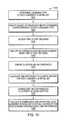
- FIG. 3is a flow diagram depicting an example sequence of steps for determining an initial set of landmarks at which the mobile electronic device may be located;
- FIG. 4is a schematic diagram illustrating the selection of an example initial set of landmarks based upon an initial estimated location and an accuracy
- FIG. 5is a flow diagram of an example sequence of steps for selecting a most likely landmark from the initial set and “snapping” the mobile electronic device's location thereto;
- FIG. 6is a block diagram of a location determination application that includes a Likelihood Engine having a plurality of separate probability modules;
- FIG. 7is a flow diagram of an example sequence of steps that may be executed by a distance module to produce a likelihood value
- FIG. 8is a schematic diagram illustrating the use of one or more landmark clusters by a location pattern module
- FIG. 9is a flow diagram of an example sequence of steps that may be executed by a location pattern module to produce a likelihood value
- FIG. 10is a flow diagram of an example sequence of steps that may be executed by a time pattern module to produce a likelihood value based on temporal clusters;
- FIG. 11is a flow diagram of an example sequence of steps that may be executed by a time pattern module to produce likelihood values based on average distance;
- FIG. 12is a flow diagram of an example sequence of steps that may be executed by a business hour module to produce likelihood values.
- FIG. 1is a block diagram of a example environment 100 for operating a mobile electronic device 200 .
- the mobile electronic device 200may be any of a variety of types of devices, for example a cellular telephone, a personal digital assistant (PDA), a Personal Navigation Device (PND), a handheld computer, a notebook computer, or other type of movable device.
- the device 200may interface via a connection 110 with a communication network 120 .
- a connection 110with a communication network 120 .
- any of a variety of types of connections 110 and communication networks 120may be used.
- connection 110may be Code division multiple access (CDMA) connection, a Global System for Mobile communications (GSM) connection, or other type of cellular connection.
- CDMACode division multiple access
- GSMGlobal System for Mobile communications
- Such connection 110may implement any of a variety of types of data transfer technology, such as Single Carrier Radio Transmission Technology (1xRTT), Evolution-Data Optimized (EVDO) technology, General Packet Radio Service (GPRS) technology, Enhanced Data rates for GSM Evolution (EDGE) technology, or other data transfer technology.
- the communication network 120may include a cellular network that has a plurality of cell sites of overlapping geographic coverage, interconnected by cellular telephone exchanges. These cellular telephone exchanges may be coupled to a network backbone, for example, the public switched telephone network (PSTN), a packet-switched data network, or to other types of networks.
- PSTNpublic switched telephone network
- packet-switched data networkor to other types of networks.
- connection 110may be Wireless Fidelity (Wi-Fi) connection, a Worldwide Interoperability for Microwave Access (WiMAX) connection, or another type of wireless data connection.
- the communication network 120may include one or more wireless access points coupled to a local area network (LAN), a wide area network (WAN), the Internet, or other packet-switched data network.
- connection 110may be a wired connection, for example an Ethernet link
- the communication networkmay be a local area network (LAN), a wide area network (WAN), the Internet, or other packet-switched data network. Accordingly, a variety of different configurations are expressly contemplated.
- a plurality of servers 130may be coupled via interfaces to the communication network 120 , for example, via wired or wireless interfaces. These servers 130 may be configured to provide various types of services to the mobile electronic device 200 .
- one or more servers 130may execute location based service (LBS) applications 140 , which interoperate with software executing on the device 200 , to provide LBS's to a user.
- LBSlocation based service
- Such an LBStypically utilizes knowledge of the device's location, and/or the location of other devices, to provide location-specific information, notifications, interactive capabilities, and/or other functionality to a user.
- Knowledge of the device's location, and/or the location of other devicesmay be obtained through interoperation of the device 200 with a location determination application 150 executing on one or more of the servers 130 .
- the location determination application 150may implement a novel technique for determining the location of the device 200 to a greater level of accuracy than possible using prior known techniques.
- FIG. 2is a block diagram of an example mobile electronic device 200 .
- the device 200may include a processing unit (PU) 210 .
- the PU 210may be any of a variety of different types of commercially available processors suitable for mobile devices, for example, an XScale architecture microprocessor, a Microprocessor without Interlocked Pipeline Stages (MIPS) architecture processor, or another type of processor.
- a memory 220such as a Random Access Memory (RAM), a Flash memory, or other type of memory, is typically accessible to the processor.
- the memory 220may be adapted to store an operating system (OS) 230 , as well as application programs 240 , such as a mobile location enabled application that may provide LBS's to a user.
- OSoperating system
- application programs 240such as a mobile location enabled application that may provide LBS's to a user.
- the processor 210may be coupled, either directly or via appropriate intermediary hardware, to a display 250 and to one or more input/output (I/O) devices 260 , such as a keypad, a touch panel sensor, a microphone, etc.
- the processor 210may be coupled to a transceiver 270 that interfaces with an antenna 290 .
- the transceiver 270may be configured to both transmit and receive cellular network signals, wireless data signals, or other types of signals via the antenna 290 , depending on the nature of the device 200 . In this manner the connection 110 with the communication network 120 may be established.
- a GPS receiver 280may also make use of the antenna 290 to receive GPS signals.
- LBS'smay require, or operate best with, highly accurate knowledge of the location of a mobile electronic device 200 .
- the present disclosuredescribes a technique for determining a device's location to a greater level of accuracy than previously generally achievable.
- FIG. 3is a flow diagram depicting an example sequence of steps for determining an initial set of landmarks at which a mobile electronic device 200 may be located. Such steps may be implemented by computer executable instructions of the location determination application 150 executing on the one or more of the servers 130 . Further, at least some portions of the steps may be implemented by computer executable instruction of the OS 230 or an application program 240 executing on the device 200 , by special purpose hardware devices, or by other appropriate components.
- an initial estimated location of the device 200is determined using one of a number of LDMs.
- the particular LDM employedmay depend upon the capabilities of the device 200 , the location determination infrastructure accessible to the device, and/or other factors.
- the device 200includes an A-GPS enabled GPS receiver 280 , is able to receive GPS signals 160 transmitted by GPS satellites 170 , and is able to receive comparison data, telemetry data, and/or ionospheric condition data from one or more assistance servers 180 , A-GPS may be used to determine the initial estimated location.
- the device 200is capable of communicating with cell sites, and if data records that indicate the locations of the cell sites are accessible, a nearest cell site association operation, or a triangulation calculation, may be performed to determine the initial estimated location.
- the device 200is capable of communicating with access points, and if data records indicating the locations of such access points are accessible, a nearest access point association operation, or a triangulation calculation, may be performed to determine the initial estimated location.
- the device 200may prompt a user to self-report a location by inputting a text-string, for example a street address; by making a selection, for example by selecting a point on a map; or by some other interactive technique.
- the inputted text-stringmay be provided via the connection 110 and communication network 120 to a geocoding application executing on a server 130 .
- the geocoding applicationmay translate the text-string into geographic coordinates. Such geographic coordinates may be used as the initial estimated location.
- a wide variety of other LDMsmay be alternatively employed.
- an accuracyis determined for the initial estimated location.
- the accuracymay be based upon an assumed accuracy for the particular LDM employed.
- the LDMis A-GPS
- an assumed accuracy of approximately 300 feetmay be used.
- Such assumed accuracyprovides for worst-case performance that may be experienced in an urban area, where line-of-sight to satellites 170 may be obstructed, and multi-path interference may be considerable.
- the assumed accuracytakes into account the normal distribution (i.e., Gaussian distribution) of accuracy for locations calculated by A-GPS. That is, the device 200 is more likely actually located at the location returned in the A-GPS calculation than remote therefrom.
- the LDMis associated with the known location of a nearest cell site, an assumed accuracy of approximately 2-10 miles may be used. Such assumed accuracy provides for worst-case spacing of cell sites, for example extended spacing common in suburban areas. Further, the assumed accuracy takes into account the generally even distribution of accuracy for locations calculated by this LDM. That is, there is typically an equal likelihood that the location provided (i.e. the location of the cell site) is the actual location of the device 200 , as there is that it is highly inaccurate (for example, the device 200 is actually located at the maximum range of the cell site).
- the LDM employedis associated with the known location of the nearest access point, and assuming that the access point is implementing Wi-Fi, an assumed accuracy of approximately 100 feet may be used. This assumed accuracy may account for the even distribution of accuracy typically representative of this LDM.
- the assumed accuracymay be determined based upon the specificity of the information provided by the user. For example, if the user inputs a text string including only city and state names, an assumed accuracy of approximately 5 miles may be used, corresponding to a citywide scope. Alternatively, if the user inputs a string that also includes a street address, an assumed accuracy of about 50 ft may be used, corresponding to a building-wide scope. As with other of the above described LDMs, it may be assumed that self-reported locations have an even accuracy distribution.
- the assumed accuracy for the LDMmay be used directly or, in some cases, further refined.
- the assumed accuracymay be refined by adjustments for actual building density in the vicinity of the mobile electronic device 200 , if such information is obtainable.
- the assumed accuracymay be adjusted to indicate greater accuracy for areas with low building density, or adjusted to indicate decreased accuracy for dense urban areas.
- the assumed accuracymay be adjusted in light of an accuracy history.
- the LDMis based upon the known location of cell towers or access points, the accuracy can be refined if the density of such cell towers or access points is known for the general area.
- the difference between the user's A-GPS calculated location and the known location of landmarksmay show the accuracy typical in the area. If sufficient quantities of such data are available, the assumed accuracy may be adjusted in light thereof. Alternatively a variety of other refinement techniques may be employed.
- an initial set of landmarksis determined, based upon the initial estimated location and the determined accuracy.
- the term “landmark”should be interpreted broadly to encompass a variety of types of places of known location, including points of interest (POIs), such as attractions, businesses, restaurants, etc; user-specific places, for example a user's home, workplace, friend's homes, etc.; previously visited places, whose location may have been previously determined; and/or other types of places.
- a record of landmarks for the geographic area covered by the system 100 , or a portion thereof,may be stored in one or more databases 190 - 194 accessible to the location determination application 150 .
- a POI database 190a user-specific places database 192 , and a location history database 194 may be maintained.
- the location determination application 150selects landmarks from the databases 190 - 194 that fall within a radius extending from the initial estimated location.
- a radiusmay equal the determined accuracy of the LDM.
- an accuracy radius 410may be envisioned to extend from an initial estimated location 420 to establish a circumference 425 .
- Landmarks B 440 and C 450fall within the circumference 430 , and thus form an initial set of landmarks ⁇ A,B ⁇ .
- Landmarks A 460 , D 470 , and E 480fall outside the circumference 425 and thus are excluded from the initial set.
- FIG. 5is a flow diagram of an example sequence of steps 500 for selecting a most likely landmark from the initial set, and “snapping” the mobile electronic device's location thereto.
- the term “snap”should be interpreted broadly to encompass setting, assigning, providing as, or otherwise using the location as the location of the device 200 .
- the steps shown in FIG. 5may be implemented by computer executable instructions of the location determination application 150 executing on the one or more of servers 130 . Further, at least some portions of the steps may be implemented by computer executable instructions of the OS 230 or an application program 240 executing on hardware of the mobile electronic device 200 , by special purpose hardware devices, or by other appropriate components.
- an “overriding” rules checkis performed.
- certain “overriding” rulesmay preempt the results returned from the Likelihood Engine 610 .
- These rulesmay be based on certain generalizations regarding user activity. For example, a generalization may be made that if the user of the device 200 is still within a same general vicinity for a certain time frame, for example, 30 minutes, the location of the device 200 has not changed. Likewise, if the user of the device 200 is still within or returning to the same vicinity and a last n user-selected locations for the device 200 are all identical, a generalization may be made that the device 200 is still there. Similarly, a variety of other rules are possible. When such rules apply, it may be assumed the device 200 is still about the last landmark associated with the device 200 . In such cases, execution may proceed to step 540 where the location of the device 200 is automatically “snapped” to a last known location.
- each landmark in this initial setis analyzed, and a likelihood that the device 200 is located proximate to the landmark is calculated.
- This calculationmay be performed by a Likelihood Engine.
- the Likelihood Engine 610may include a plurality of separate probability modules 620 - 655 , that each determines a likelihood that the device 200 is located at a landmark.
- Each probability modules 620 - 655may implement a different algorithm, which makes different assumptions regarding user activity, societal practices, and/or the environment, to calculate likelihood values.
- the probability modules 620 - 655may be classified into two general types.
- a first typeis history-dependent and analyzes landmarks based upon patterns occurring in places previously visited by the user (within a particular timeframe).
- the history-dependent probability modulesmay include a location pattern module 625 , a time pattern module 630 , a repeatedly visited places module 655 , as well as other modules.
- the second typeis history-independent and analyzes landmarks independent of previous activity. Such modules instead look to intrinsic properties of the landmarks and the current environment.
- History-independent probability modulesmay include a distance module 620 , a business hour module 635 , an event module 640 , a season/weather module 645 , a common place name module 650 , as well as other modules. Details of the inner operation of each of the probability modules 620 - 655 is reserved for discussion further below.
- Each probability module 620 - 655generates a likelihood value for each landmark of the initial set. This likelihood represents the probability that the landmark is the actual location of the device 200 . These likelihood values may be normalized.
- the assumptions underlying a particular probability modulemay not be applicable to a particular landmark of the initial set of landmarks.
- the assumptions underlying the business hour module 635may not be applicable to landmarks that do not have associated business hours.
- the inapplicable modulemay simply not be used with the particular landmark. In this manner, results from inapplicable modules may be prevented from inadvertently skewing landmark selection.
- the likelihood values generated by each of the probability modules 620 - 655are combined by an aggregation engine 660 of the Likelihood Engine 610 , to generate an overall likelihood that the device 200 is located at each landmark in the initial set.
- the aggregation engine 660calculates a normalized sum (e.g., an average) of the likelihood values from the probability modules 620 - 655 , for instance by implementing the equation:
- LL 1 + L 2 + ⁇ ... ⁇ ⁇ L n n ( 1 )
- Lis the overall likelihood for a particular landmark
- L 1 , L 2 . . . to L nare likelihood values generated by probability modules 620 - 655
- nis the number of probability modules 620 - 655 for which likelihood values are provided.
- the aggregation engine 660may assign weights to each likelihood values based on preferences for particular probability modules 620 - 655 , for instance by implementing the equation:
- the landmark of the initial set of landmarks with the highest overall likelihoodis selected, based on the overall likelihoods returned by the aggregation engine 660 .
- a confidence determinationis performed on the selected landmark.
- the confidence determinationmay compare the likelihood the selected landmarks is the location of the device 200 , with the likelihood one or more other landmark candidates in the initial set are the location of the device 200 , yielding a statistical measure of selection confidence. If this confidence measure exceeds a predetermined threshold, then the match is declared confident Likewise, if the measure falls below the threshold, the selection is declared non-confident.
- step 570the location determination application 150 “snaps” the location of the mobile electronic device 200 to the known location of the selected landmark. That is, the device 200 may be set to the known location of the selected landmark, and the landmark's location used rather than the initial estimated location returned by the LDM.
- step 580the user of the device 200 is presented with a description of the selected landmark, as well as one or more other landmark candidates, for example via the display 250 .
- the descriptionmay be text-based, such as a landmark name; graphical, such as a map marked with icon; or take on some other form.
- step 590the user manually selects a best landmark from those presented, for example by using an I/O device 260 of the mobile electronic device 200 . Thereafter, exaction proceeds to step 550 , where the location determination application 150 “snaps” the location of the device 200 to the location of the manually selected landmark. The location of the device 200 may then be reported to a user, for example via the device's display 250 , used with one or more LBS's, for example provided to location based service application 140 , or otherwise utilized.
- a distance module 620 of the Likelihood Engine 610may operate on the assumption that it is more likely that a user of the device 200 is at a landmark of the initial set close to the initial estimated location, than at a landmark further away from the initial estimated location. For example, in reference to FIG. 4 , Landmark C 450 may be accorded a greater likelihood than Landmark B 440 , based on its closer proximity to the initial estimated location 420 .
- FIG. 7is a flow diagram of an example sequence of steps 700 that may be executed by the distance module 620 to produce a likelihood value.
- the distance from the initial estimated location 420 to each landmark in the initial setis calculated.
- the distancesare normalized. For example, the distances may be divided by the accuracy of the LDM. The result of such normalization may be a value between zero and one.
- the normalized likelihood each landmarkis the actual location of the mobile electronic device 200 is calculated.
- Such likelihoodsare based on the normalized distance and the accuracy distribution of the LDM, and may be determined by the equation:
- L distancerepresents the normalized likelihood
- D normailzedis the normalized distance from the initial estimated location 420 to the landmark
- RMSis a root mean square (i.e., the quadratic mean) of the accuracy distribution of the LDM. In some cases, RMS may be approximated by a constant to simplify the calculation.
- the assumptions underlying the distance module 620typically are appropriate for initial estimated locations produced by LDMs that have a normal, or other non-even, accuracy distribution. In some implementations, use of the module 620 may be confined to situations where such LDMs are employed.
- a location pattern module 625 of the Likelihood Engine 610may operate on the assumption that if there are clusters of previously visited landmarks around the initial estimated location, it is more likely that a user of the device 200 is located at a landmark in a cluster, than at a landmark remote to a cluster.
- landmarks A 805 , C 815 , D 820 and F 830represent places previously visited (within a predetermined timeframe) by the user of the device 200 . Such visits may be recorded in the location history database 190 maintained by a server 130 .
- a clustermay be established about a cluster center 860 and extend along a radius 890 to a cluster perimeter 870 .
- the cluster perimeterincludes landmarks A 805 , C 815 , D 820 and F 830 , as well as other landmarks, such as previously non-visited landmarks B 810 and E 825 . All the landmarks 805 - 830 within the cluster perimeter 870 may be accorded a greater likelihood value than landmarks remote from the cluster, such as landmarks G 840 , H 845 and 1850 .
- the assumptions underlying the location pattern module 625typically are best suited for use with LDMs that have a relatively low accuracy, such that a sufficient number of locations fall within the accuracy perimeter 425 to establish one or more clusters. However, in some cases, the module 625 may be used with LDMs having greater accuracy by considering previously visited landmarks beyond the accuracy perimeter 425 for the limited purpose of identifying clusters. Accordingly, the below discussed “search area” 895 may coincide with the accuracy perimeter 425 , or may be defined differently.
- FIG. 9is a flow diagram of an example sequence of steps 900 that may be executed by the location pattern module 625 to produce likelihood values based upon a location pattern.
- a clustering algorithmis employed to determine one or more clusters within, or at least partially within, the accuracy perimeter 425 , considering landmarks within the search area 895 .
- the clustering algorithmis a quality threshold (QT) clustering algorithm.
- a QT clustering algorithmadvantageously does not require specification of a number of clusters a priori.
- the algorithmtakes as an input a maximum cluster extent, which here may be envisioned as the cluster radius 890 .
- the cluster radius 890is specified to be one half the radius 898 of the search area 895 .
- the QT clustering algorithmbuilds a candidate cluster for each previously visited landmark 805 , 815 , 820 , 830 , by including the closest previously visited landmark, the next previously visited landmark, and so on, until the distance to the next landmark surpasses the cluster extent.
- the algorithmsaves the candidate cluster with the most landmarks as a first true cluster, and removes all landmarks in this cluster from further consideration.
- the algorithmthen recurses, using the reduced set of landmarks.
- One or more clustersmay be returned as a final result. Further details regarding QT clustering algorithms may be found in Exploring Expression Data: Identification and Analysis of Coeexpressed Genes , by Heyer, L. J., Kruglyak, S. and Yooseph, S., Genome Research, 9:1106-1115 which is incorporated herein by reference.
- clustering algorithmsmay be employed.
- a K-mean clustering algorithma fuzzy c-means clustering algorithm, and/or another type of clustering algorithm may be used.
- clusters that include less than a predetermined threshold of previously visited landmarksmay be ignored.
- the distance from each landmark in the initial set of landmarks to the closest cluster centeris calculated.
- these distancesare normalized by division by a maximum possible distance. For example, in one implementation the maximum possible distance may be two times the radius 898 of the search area 895 .
- a normalized likelihoodis calculated for each landmark, indicating the likelihood that the landmark is the actual location of the device 200 .
- L Location_Cluster1 - dist ⁇ ( landmark , cluster_center ) 2 * search_radius ( 4 )
- L Location — Clusterrepresents the normalized likelihood
- distis a distance function
- landmarkis the location of a landmark of the initial set of landmarks
- cluster_centeris the location of the nearest cluster center
- search_radiusis the search radius 898 .
- a time pattern module 630 of the Likelihood Engine 610may operate on the assumption that if a user of the device 200 usually visits a certain type of landmark around the same time of day, it is more likely that the device 200 is located at that type of landmark at about that time, than at a different type of landmark.
- the time of previous visitsmay be recorded in the location history database 190 .
- Types of landmarksmay be determined in a variety of different manners. The type of a landmark may be determined by parsing the landmark's name. For example, a name that includes the words “restaurant,” “diner,” “bistro,” etc. may be classified as “restaurant” type landmarks.
- the type of a landmarkmay be determined by looking to an assigned category. For example, landmarks may be stored in categorized data records within the location history database 190 . In yet another alternative, the type of a landmark may be determined by looking to an associated type identifier that has either been manually, or automatically, assigned to the landmark.
- the time pattern module 630calculates the likelihood that each landmark is the actual location of the device 200 employing a clustering algorithm similar to that employed in the location pattern module 625 discussed above.
- FIG. 10is a flow diagram of an example sequence of steps 1000 that may be executed by a time pattern module 630 to produce a likelihood value based on temporal clusters.
- a landmark typeis determined.
- a subset of previously visited landmarksis identified that corresponds to each landmark type.
- time-of-visit recordsare accessed.
- a clustering algorithmis executed on each subset of landmarks and time-of-visit records associated therewith. For example, a QT clustering algorithm, a K-mean clustering algorithm, a fuzzy c-means clustering algorithm, and/or another type of clustering algorithm may be employed.
- clusters returned by the clustering algorithmare analyzed and any clusters that include less than a predetermined threshold of visits are ignored.
- a time difference from the present time to a time associated with the cluster centeris calculated.
- the time difference to the closest cluster centeris normalized, for example, by dividing by a maximum possible time difference (e.g., 12 hours).
- these normalized time differencesare used to calculate likelihoods each landmark of the initial set is the actual location of the device 200 .
- L Time_Cluster1 - dist ⁇ ( current_time , cluster_center ) max_time ⁇ _difference ( 5 ) is where L Time — Cluster represents the normalized likelihood that a landmark in the initial set is the actual location of the mobile electronic device 200 , dist is a time distance function, e.g., a time difference, current_time is a time associated with the initial estimated location 420 , cluster_center is a time associated with the cluster center of the closest cluster, and max_time_difference is a predetermined maximum possible time difference used to normalize the results.
- an adjustment factormay be included based upon how closely a landmark matches a landmark type. For example, if landmark type is determined by parsing a landmark's name, a closeness of match may be based on the specific match words, or the number of match words, that are found. Similarly, if type is determined by categorization within a location history database 190 , category hierarchies may be employed. A match at a “super-category” level may represent only a general thematic relation, while a match at a “sub-category” level may represent a more concrete relation. A graph distance may be calculated that represents the closeness of match.
- the likelihood adjustedbased on the closeness of match.
- the size of a clustermay be used to adjust the likelihood. For example, if the closest cluster is a “large” cluster, an upwards adjustment may be made reflecting higher probabilities. If the closest cluster is a “small” cluster, a downwards adjustment may be made.
- the time pattern module 630may calculate the likelihood that each landmark is the actual location of the mobile electronic device 200 by looking to average distances.
- FIG. 11is a flow diagram of an example sequence of steps 1100 that may be executed by a time pattern module 630 to produce likelihood values based on average distances.
- a landmark typeis determined.
- a subset of previously visited landmarksis identified that corresponds to each landmark type.
- time-of-visit recordsare accessed.
- a time differenceis calculated between the time associated with that landmark and a time associated with the initial estimated location.
- a business hour module 635 of the Likelihood Engine 610may operate on the assumption that it is more likely that a user of the device 200 is visiting a landmark where the current time falls within the landmark's business hours, than a landmark where the current time is outside the business hours. That is, it is more likely that a user is at a landmark that is likely “open,” than at one that is likely “closed.”
- FIG. 12is a flow diagram of an example sequence of steps 1200 that may be executed by a business hour module 635 to produce likelihood values.
- a corresponding landmark typeis determined.
- each landmarkis associated with a predefined set of business hours for that landmark type.
- a landmark type corresponding to “business facilities”may be associated with predefined business hours of 8:00 am to 5:00 pm
- a landmark type corresponding to “retail”may be associated with predefined business hours of 9:00 am to 9:00 pm.
- a time offset for that landmarkis calculated by taking the difference of the time associated with the initial estimated location and the nearest business hour cutoff. For example, if the time associated with the initial estimated location was 5:15 pm, and the business hours were 8 am to 5 pm, a difference of 15 minutes would be calculated. For times which fall within the business hours, the time offset would be zero.
- each time offsetis normalized, for example, by division by a maximum time offset and subtraction from one, to determine a likelihood that each landmark of the initial set of landmarks is the actual location of the mobile electronic device 200 .
- the likelihoodwill be assigned a high value, for example a value of one, when within the business hours, while a lesser value is assigned when outside of business hours.
- L Business_Hour ⁇ s1 - time_offset max_time ⁇ _offset ( 6 )
- L Business — Hoursrepresents the normalized likelihood that a landmark in the initial set is the actual location of the mobile electronic device 200
- time_offsetis the difference of a time associated with the initial estimated location and the nearest business hour cutoff
- max_time_offestis a predetermined maximum time offset used to normalize and/or otherwise adjust the results.
- business hours for specific establishmentsmay be obtained, for example, by querying a pre-loaded database, parsing data available on websites associated with establishments, querying a user, or by other techniques.
- adjustmentsmay be made for times proximate to the beginning and end of business hour periods, so that such scenarios are not unduly penalized in the algorithm.
- An event module 640 of the Likelihood Engine 610may operate on the assumption that it is more likely that a user of the device 200 is visiting a place that hosts events during an event, than that the user is visiting a place that host events when no event is occurring. Such module 640 may operate in a similar manner to the business hour module 635 discussed above. Rather than business hours, event hours may be obtained for each landmark of the initial set that hosts events. Event hours may be obtained by querying an event database, for example, the event database commercially available from Eventful, Inc. of San Diego, Calif., an event database provided by another similar service provider, or by other techniques. Therafter, an equation similar to equation (6) above may be employed.
- a season/weather module 645 of the Likelihood Engine 610may operate on the assumption that it is more likely that a user of the device 200 is visiting a weather-dependent place in appropriate weather conditions, than in inappropriate weather conditions. For example, it is more likely that a user is visiting an outdoor recreational site, such as a beach or a park, if it is sunny and warm, than if it is cold and snowing. Such module 645 may assume certain appropriate season and weather conditions based upon event types determined according to the techniques discussed above. Further, current weather information for the vicinity about the initial estimated location 420 may be obtained by querying a weather database, for example the weather database commercially available from AccuWeather, Inc. of State College, Pa., from a database provided by another similar service provider, or by other techniques.
- a weather databasefor example the weather database commercially available from AccuWeather, Inc. of State College, Pa., from a database provided by another similar service provider, or by other techniques.
- a common place names module 650 of the Likelihood Engine 610may operate on the assumption that it is generally more likely that a user of the device 200 is visiting a landmark with a certain place name, than a landmark with another name. For example, a list of certain common place names, such as “home,” “office,” “work,” etc., may be established for places where users tend to be located for much of their time. Landmarks in the initial set with names that match, or include, these common place names may be accorded a favored status, and assigned higher likelihood values than other landmarks.
- a repeatedly visited places module 655 of the Likelihood Engine 610may operate on the assumption that it is generally more likely that a user of the device 200 is returning to a previously visited place than is visiting a new place. Accordingly, a general algorithm may be employed where previously visited landmarks (as indicated by the location history database 190 ) are accorded a higher likelihood than landmarks that have not been previously visited.
- overriding rulesare discussed above as preempting the results returned from the Likelihood Engine 610 .
- such rulesmay be incorporated into separate probability modules incorporated into the Likelihood Engine 610 , serving as one factor among many, rather than overriding other results.
- a single LDMis used to determine the initial estimated location
- a combination of two or more LDMsmay be employed.
- the accuracies of the two or more LDMsmay be combined to determine an appropriate accuracy radius 410 .
Landscapes
- Engineering & Computer Science (AREA)
- Radar, Positioning & Navigation (AREA)
- Remote Sensing (AREA)
- Automation & Control Theory (AREA)
- Physics & Mathematics (AREA)
- General Physics & Mathematics (AREA)
- Navigation (AREA)
Abstract
Description
where L is the overall likelihood for a particular landmark, L1, L2. . . to Lnare likelihood values generated by probability modules620-655, and n is the number of probability modules620-655 for which likelihood values are provided.
where W1, W2. . . to Wnare weights associated with each probability module620-655.
where LLocation
is where LTime
where LBusiness
Claims (26)
Priority Applications (1)
| Application Number | Priority Date | Filing Date | Title |
|---|---|---|---|
| US12/016,112US7822426B1 (en) | 2008-01-17 | 2008-01-17 | System and method for snapping a user location to a landmark of known location |
Applications Claiming Priority (1)
| Application Number | Priority Date | Filing Date | Title |
|---|---|---|---|
| US12/016,112US7822426B1 (en) | 2008-01-17 | 2008-01-17 | System and method for snapping a user location to a landmark of known location |
Publications (1)
| Publication Number | Publication Date |
|---|---|
| US7822426B1true US7822426B1 (en) | 2010-10-26 |
Family
ID=42987588
Family Applications (1)
| Application Number | Title | Priority Date | Filing Date |
|---|---|---|---|
| US12/016,112Expired - Fee RelatedUS7822426B1 (en) | 2008-01-17 | 2008-01-17 | System and method for snapping a user location to a landmark of known location |
Country Status (1)
| Country | Link |
|---|---|
| US (1) | US7822426B1 (en) |
Cited By (61)
| Publication number | Priority date | Publication date | Assignee | Title |
|---|---|---|---|---|
| US20080091757A1 (en)* | 2006-09-08 | 2008-04-17 | Ingrassia Christopher A | System and method for web enabled geo-analytics and image processing |
| US20080294678A1 (en)* | 2007-02-13 | 2008-11-27 | Sean Gorman | Method and system for integrating a social network and data repository to enable map creation |
| US20090238079A1 (en)* | 2008-03-20 | 2009-09-24 | Dieter Gantenbein | Method and Apparatus for Discovery and Tracking of Location of Networked Devices |
| US20090238100A1 (en)* | 2004-07-30 | 2009-09-24 | Fortiusone, Inc | System and method of mapping and analyzing vulnerabilities in networks |
| US20090264136A1 (en)* | 2008-04-18 | 2009-10-22 | Qualcomm Incorporated | System and/or method for reducing initial position uncertainty in sps operation |
| US20100198917A1 (en)* | 2009-02-02 | 2010-08-05 | Kota Enterprises, Llc | Crowd formation for mobile device users |
| US20100279705A1 (en)* | 2005-03-22 | 2010-11-04 | Qualcomm Incorporated | Methods and systems for deriving seed position of a subscriber station in support of unassisted gps-type position determination in a wireless communication system |
| US20100306372A1 (en)* | 2003-07-30 | 2010-12-02 | Gorman Sean P | System and method for analyzing the structure of logical networks |
| US20120064919A1 (en)* | 2009-08-24 | 2012-03-15 | Waldeck Technology, Llc | Crowd creation system for an aggregate profiling service |
| US20120089326A1 (en)* | 2010-10-08 | 2012-04-12 | Thomas Bouve | Selected driver notification of transitory roadtrip events |
| US8175851B1 (en)* | 2009-09-24 | 2012-05-08 | L-3 Services, Inc. | Using statistical learning methods to fuse parameter estimates |
| US20120129487A1 (en)* | 2010-11-24 | 2012-05-24 | Apple Inc. | Optimized system selection using location estimation |
| US20120166147A1 (en)* | 2010-12-23 | 2012-06-28 | Electronics And Telecommunications Research Institute | Method for generating digital interior map |
| US20120330722A1 (en)* | 2011-06-27 | 2012-12-27 | Cadio, Inc. | Adjusting a process for visit detection based on location data |
| US8385964B2 (en) | 2005-04-04 | 2013-02-26 | Xone, Inc. | Methods and apparatuses for geospatial-based sharing of information by multiple devices |
| US20130316734A1 (en)* | 2010-11-01 | 2013-11-28 | Wavemarket Inc. | System and Method for Aggregating and Associating Mobile Device Location Data |
| US8666432B2 (en) | 2011-08-11 | 2014-03-04 | Rf Spot Inc. | Method and system for indoor RF mapping |
| US20140143240A1 (en)* | 2012-11-21 | 2014-05-22 | Institute For Information Industry | Information search server and information search method thereof |
| WO2014105300A1 (en)* | 2012-12-29 | 2014-07-03 | Google Inc. | Methods and systems for determining fleet trajectories to satisfy a sequence of coverage requirements |
| US8782560B2 (en) | 2009-12-22 | 2014-07-15 | Waldeck Technology, Llc | Relative item of interest explorer interface |
| US8781495B1 (en) | 2011-04-26 | 2014-07-15 | Andrew Joseph Gold | Method and system for indoor RF mapping |
| US8818409B1 (en) | 2012-11-01 | 2014-08-26 | Sprint Communications Company L.P. | Identification of frequent locations of a wireless communication device |
| US8977287B1 (en) | 2011-04-26 | 2015-03-10 | Andrew Joseph Gold | Method and system for indoor RF mapping |
| US9008685B1 (en) | 2011-04-26 | 2015-04-14 | Andrew Joseph Gold | Method and system for indoor RF mapping |
| US9013350B2 (en) | 2009-07-16 | 2015-04-21 | Skyhook Wireless, Inc. | Systems and methods for using a satellite positioning system to detect moved WLAN access points |
| US20150235161A1 (en)* | 2014-02-14 | 2015-08-20 | Bby Solutions, Inc. | Wireless customer and labor management optimization in retail settings |
| US9175973B2 (en) | 2014-03-26 | 2015-11-03 | Trip Routing Technologies, Llc | Selected driver notification of transitory roadtrip events |
| US9179257B2 (en) | 2013-08-21 | 2015-11-03 | Pitney Bowes Inc. | Method and system for determining high precision geo-fencing using business property boundaries |
| US20150356703A1 (en)* | 2014-06-10 | 2015-12-10 | Uber Technologies, Inc. | Arranging a transport service based on computed vectors associated with service providers |
| US9300704B2 (en) | 2009-11-06 | 2016-03-29 | Waldeck Technology, Llc | Crowd formation based on physical boundaries and other rules |
| US9336302B1 (en) | 2012-07-20 | 2016-05-10 | Zuci Realty Llc | Insight and algorithmic clustering for automated synthesis |
| DE102014226186A1 (en)* | 2014-12-17 | 2016-06-23 | Bayerische Motoren Werke Aktiengesellschaft | Improvements to high accuracy maps |
| US9754492B2 (en) | 2014-07-08 | 2017-09-05 | The Toronto-Dominion Bank | Systems and methods for providing sensor-based location proximity detection and notification |
| US9813510B1 (en) | 2016-09-26 | 2017-11-07 | Uber Technologies, Inc. | Network system to compute and transmit data based on predictive information |
| US9852551B2 (en) | 2015-02-05 | 2017-12-26 | Uber Technologies, Inc. | Programmatically determining location information in connection with a transport service |
| US9939279B2 (en) | 2015-11-16 | 2018-04-10 | Uber Technologies, Inc. | Method and system for shared transport |
| US10013639B1 (en) | 2013-12-16 | 2018-07-03 | Amazon Technologies, Inc. | Analyzing digital images based on criteria |
| CN108566675A (en)* | 2017-12-04 | 2018-09-21 | 西安电子科技大学 | WiFi indoor orientation methods based on multiple AP selection |
| WO2019000468A1 (en)* | 2017-06-30 | 2019-01-03 | 广东欧珀移动通信有限公司 | User location identification method and apparatus, storage medium, and electronic device |
| US10192387B2 (en) | 2016-10-12 | 2019-01-29 | Uber Technologies, Inc. | Facilitating direct rider driver pairing for mass egress areas |
| US10355788B2 (en) | 2017-01-06 | 2019-07-16 | Uber Technologies, Inc. | Method and system for ultrasonic proximity service |
| US10354535B1 (en) | 2012-12-27 | 2019-07-16 | Loon Llc | Methods and systems for determining when to launch vehicles into a fleet of autonomous vehicles |
| US10685416B2 (en) | 2015-12-10 | 2020-06-16 | Uber Technologies, Inc. | Suggested pickup location for ride services |
| US10688919B2 (en) | 2014-05-16 | 2020-06-23 | Uber Technologies, Inc. | User-configurable indication device for use with an on-demand transport service |
| US10731998B2 (en) | 2017-11-05 | 2020-08-04 | Uber Technologies, Inc. | Network computer system to arrange pooled transport services |
| US10867330B2 (en) | 2014-02-07 | 2020-12-15 | Uber Technologies, Inc. | User controlled media for use with on-demand transport services |
| CN112313538A (en)* | 2019-11-05 | 2021-02-02 | 深圳市大疆创新科技有限公司 | Target detection method, radar, device and storage medium |
| US11010693B2 (en) | 2014-08-04 | 2021-05-18 | Uber Technologies, Inc. | Determining and providing predetermined location data points to service providers |
| US11047700B2 (en) | 2019-02-01 | 2021-06-29 | Uber Technologies, Inc. | Navigation and routing based on image data |
| US11107019B2 (en) | 2014-07-30 | 2021-08-31 | Uber Technologies, Inc. | Arranging a transport service for multiple users |
| US11153395B2 (en) | 2017-10-10 | 2021-10-19 | Uber Technologies, Inc. | Optimizing multi-user requests for a network-based service |
| US11205103B2 (en) | 2016-12-09 | 2021-12-21 | The Research Foundation for the State University | Semisupervised autoencoder for sentiment analysis |
| US11229001B2 (en)* | 2017-04-19 | 2022-01-18 | International Business Machines Corporation | IP address geo-position detection based on landmark sequencing |
| US11255691B2 (en)* | 2017-03-14 | 2022-02-22 | Samsung Electronics Co., Ltd. | Method for providing location-based service and electronic device therefor |
| US11355009B1 (en) | 2014-05-29 | 2022-06-07 | Rideshare Displays, Inc. | Vehicle identification system |
| US11379761B2 (en) | 2014-03-13 | 2022-07-05 | Uber Technologies, Inc. | Configurable push notifications for a transport service |
| US11386781B1 (en) | 2014-05-29 | 2022-07-12 | Rideshare Displays, Inc. | Vehicle identification system and method |
| US11570276B2 (en) | 2020-01-17 | 2023-01-31 | Uber Technologies, Inc. | Forecasting requests based on context data for a network-based service |
| US11601511B2 (en) | 2016-09-26 | 2023-03-07 | Uber Technologies, Inc. | Service information and configuration user interface |
| US20230136186A1 (en)* | 2020-04-28 | 2023-05-04 | Nippon Telegraph And Telephone Corporation | Position measurement apparatus, positioning method and program |
| US11713973B2 (en) | 2017-01-13 | 2023-08-01 | Uber Technologies, Inc. | Method and system for repositioning a service location |
Citations (11)
| Publication number | Priority date | Publication date | Assignee | Title |
|---|---|---|---|---|
| US6249252B1 (en) | 1996-09-09 | 2001-06-19 | Tracbeam Llc | Wireless location using multiple location estimators |
| US6757544B2 (en) | 2001-08-15 | 2004-06-29 | Motorola, Inc. | System and method for determining a location relevant to a communication device and/or its associated user |
| US6766245B2 (en) | 2002-03-14 | 2004-07-20 | Microsoft Corporation | Landmark-based location of users |
| US6806830B2 (en) | 2001-12-31 | 2004-10-19 | Texas Instruments Incorporated | Electronic device precision location via local broadcast signals |
| US20050198286A1 (en)* | 2004-01-30 | 2005-09-08 | Zhichen Xu | Selecting nodes close to another node in a network using location information for the nodes |
| US6963748B2 (en)* | 2001-12-26 | 2005-11-08 | Autodesk, Inc. | Mobile device locator adapter system for location based services |
| US6978258B2 (en)* | 2001-12-26 | 2005-12-20 | Autodesk, Inc. | Fuzzy logic reasoning for inferring user location preferences |
| US7199754B2 (en) | 2003-06-30 | 2007-04-03 | Microsoft Corporation | System and methods for determining the location dynamics of a portable computing device |
| US7242950B2 (en)* | 2003-02-18 | 2007-07-10 | Sbc Properties, L.P. | Location determination using historical data |
| US20070276591A1 (en)* | 2006-05-26 | 2007-11-29 | Samsung Electronics Co., Ltd. | Apparatus, method and medium detecting landmarks with a mobile device |
| US7565155B2 (en)* | 2002-04-10 | 2009-07-21 | Networks In Motion | Method and system for dynamic estimation and predictive route generation |
- 2008
- 2008-01-17USUS12/016,112patent/US7822426B1/ennot_activeExpired - Fee Related
Patent Citations (11)
| Publication number | Priority date | Publication date | Assignee | Title |
|---|---|---|---|---|
| US6249252B1 (en) | 1996-09-09 | 2001-06-19 | Tracbeam Llc | Wireless location using multiple location estimators |
| US6757544B2 (en) | 2001-08-15 | 2004-06-29 | Motorola, Inc. | System and method for determining a location relevant to a communication device and/or its associated user |
| US6963748B2 (en)* | 2001-12-26 | 2005-11-08 | Autodesk, Inc. | Mobile device locator adapter system for location based services |
| US6978258B2 (en)* | 2001-12-26 | 2005-12-20 | Autodesk, Inc. | Fuzzy logic reasoning for inferring user location preferences |
| US6806830B2 (en) | 2001-12-31 | 2004-10-19 | Texas Instruments Incorporated | Electronic device precision location via local broadcast signals |
| US6766245B2 (en) | 2002-03-14 | 2004-07-20 | Microsoft Corporation | Landmark-based location of users |
| US7565155B2 (en)* | 2002-04-10 | 2009-07-21 | Networks In Motion | Method and system for dynamic estimation and predictive route generation |
| US7242950B2 (en)* | 2003-02-18 | 2007-07-10 | Sbc Properties, L.P. | Location determination using historical data |
| US7199754B2 (en) | 2003-06-30 | 2007-04-03 | Microsoft Corporation | System and methods for determining the location dynamics of a portable computing device |
| US20050198286A1 (en)* | 2004-01-30 | 2005-09-08 | Zhichen Xu | Selecting nodes close to another node in a network using location information for the nodes |
| US20070276591A1 (en)* | 2006-05-26 | 2007-11-29 | Samsung Electronics Co., Ltd. | Apparatus, method and medium detecting landmarks with a mobile device |
Non-Patent Citations (1)
| Title |
|---|
| Heyer, Laurie, et al., "Exploring Expression Data: Identification and Analysis of Coexpressed Genes," Genome Research, http://www.genome.org, Cold Spring Harbor Laboratory Press, 1999, pp. 1105-1115. |
Cited By (158)
| Publication number | Priority date | Publication date | Assignee | Title |
|---|---|---|---|---|
| US20100306372A1 (en)* | 2003-07-30 | 2010-12-02 | Gorman Sean P | System and method for analyzing the structure of logical networks |
| US9973406B2 (en) | 2004-07-30 | 2018-05-15 | Esri Technologies, Llc | Systems and methods for mapping and analyzing networks |
| US20090238100A1 (en)* | 2004-07-30 | 2009-09-24 | Fortiusone, Inc | System and method of mapping and analyzing vulnerabilities in networks |
| US9054946B2 (en) | 2004-07-30 | 2015-06-09 | Sean P. Gorman | System and method of mapping and analyzing vulnerabilities in networks |
| US8422399B2 (en) | 2004-07-30 | 2013-04-16 | Fortiusone, Inc. | System and method of mapping and analyzing vulnerabilities in networks |
| US9194957B2 (en) | 2005-03-22 | 2015-11-24 | Qualcomm Incorporated | Methods and systems for deriving seed position of a subscriber station in support of unassisted GPS-type position determination in a wireless communication system |
| US20100279705A1 (en)* | 2005-03-22 | 2010-11-04 | Qualcomm Incorporated | Methods and systems for deriving seed position of a subscriber station in support of unassisted gps-type position determination in a wireless communication system |
| US8798645B2 (en) | 2005-04-04 | 2014-08-05 | X One, Inc. | Methods and systems for sharing position data and tracing paths between mobile-device users |
| US8831635B2 (en) | 2005-04-04 | 2014-09-09 | X One, Inc. | Methods and apparatuses for transmission of an alert to multiple devices |
| US9854402B1 (en) | 2005-04-04 | 2017-12-26 | X One, Inc. | Formation of wireless device location sharing group |
| US9584960B1 (en) | 2005-04-04 | 2017-02-28 | X One, Inc. | Rendez vous management using mobile phones or other mobile devices |
| US9883360B1 (en) | 2005-04-04 | 2018-01-30 | X One, Inc. | Rendez vous management using mobile phones or other mobile devices |
| US9467832B2 (en) | 2005-04-04 | 2016-10-11 | X One, Inc. | Methods and systems for temporarily sharing position data between mobile-device users |
| US11778415B2 (en) | 2005-04-04 | 2023-10-03 | Xone, Inc. | Location sharing application in association with services provision |
| US8385964B2 (en) | 2005-04-04 | 2013-02-26 | Xone, Inc. | Methods and apparatuses for geospatial-based sharing of information by multiple devices |
| US10149092B1 (en) | 2005-04-04 | 2018-12-04 | X One, Inc. | Location sharing service between GPS-enabled wireless devices, with shared target location exchange |
| US8538458B2 (en) | 2005-04-04 | 2013-09-17 | X One, Inc. | Location sharing and tracking using mobile phones or other wireless devices |
| US9854394B1 (en) | 2005-04-04 | 2017-12-26 | X One, Inc. | Ad hoc location sharing group between first and second cellular wireless devices |
| US9942705B1 (en) | 2005-04-04 | 2018-04-10 | X One, Inc. | Location sharing group for services provision |
| US9615204B1 (en) | 2005-04-04 | 2017-04-04 | X One, Inc. | Techniques for communication within closed groups of mobile devices |
| US11356799B2 (en) | 2005-04-04 | 2022-06-07 | X One, Inc. | Fleet location sharing application in association with services provision |
| US10165059B2 (en) | 2005-04-04 | 2018-12-25 | X One, Inc. | Methods, systems and apparatuses for the formation and tracking of location sharing groups |
| US8712441B2 (en) | 2005-04-04 | 2014-04-29 | Xone, Inc. | Methods and systems for temporarily sharing position data between mobile-device users |
| US10856099B2 (en) | 2005-04-04 | 2020-12-01 | X One, Inc. | Application-based two-way tracking and mapping function with selected individuals |
| US9955298B1 (en) | 2005-04-04 | 2018-04-24 | X One, Inc. | Methods, systems and apparatuses for the formation and tracking of location sharing groups |
| US8750898B2 (en) | 2005-04-04 | 2014-06-10 | X One, Inc. | Methods and systems for annotating target locations |
| US10791414B2 (en) | 2005-04-04 | 2020-09-29 | X One, Inc. | Location sharing for commercial and proprietary content applications |
| US10200811B1 (en) | 2005-04-04 | 2019-02-05 | X One, Inc. | Map presentation on cellular device showing positions of multiple other wireless device users |
| US10750311B2 (en) | 2005-04-04 | 2020-08-18 | X One, Inc. | Application-based tracking and mapping function in connection with vehicle-based services provision |
| US8798593B2 (en) | 2005-04-04 | 2014-08-05 | X One, Inc. | Location sharing and tracking using mobile phones or other wireless devices |
| US9253616B1 (en) | 2005-04-04 | 2016-02-02 | X One, Inc. | Apparatus and method for obtaining content on a cellular wireless device based on proximity |
| US8798647B1 (en) | 2005-04-04 | 2014-08-05 | X One, Inc. | Tracking proximity of services provider to services consumer |
| US10750309B2 (en) | 2005-04-04 | 2020-08-18 | X One, Inc. | Ad hoc location sharing group establishment for wireless devices with designated meeting point |
| US9967704B1 (en) | 2005-04-04 | 2018-05-08 | X One, Inc. | Location sharing group map management |
| US10299071B2 (en) | 2005-04-04 | 2019-05-21 | X One, Inc. | Server-implemented methods and systems for sharing location amongst web-enabled cell phones |
| US9749790B1 (en) | 2005-04-04 | 2017-08-29 | X One, Inc. | Rendez vous management using mobile phones or other mobile devices |
| US9736618B1 (en) | 2005-04-04 | 2017-08-15 | X One, Inc. | Techniques for sharing relative position between mobile devices |
| US10750310B2 (en) | 2005-04-04 | 2020-08-18 | X One, Inc. | Temporary location sharing group with event based termination |
| US9185522B1 (en) | 2005-04-04 | 2015-11-10 | X One, Inc. | Apparatus and method to transmit content to a cellular wireless device based on proximity to other wireless devices |
| US10313826B2 (en) | 2005-04-04 | 2019-06-04 | X One, Inc. | Location sharing and map support in connection with services request |
| US10341808B2 (en) | 2005-04-04 | 2019-07-02 | X One, Inc. | Location sharing for commercial and proprietary content applications |
| US9031581B1 (en) | 2005-04-04 | 2015-05-12 | X One, Inc. | Apparatus and method for obtaining content on a cellular wireless device based on proximity to other wireless devices |
| US9167558B2 (en) | 2005-04-04 | 2015-10-20 | X One, Inc. | Methods and systems for sharing position data between subscribers involving multiple wireless providers |
| US10341809B2 (en) | 2005-04-04 | 2019-07-02 | X One, Inc. | Location sharing with facilitated meeting point definition |
| US9654921B1 (en) | 2005-04-04 | 2017-05-16 | X One, Inc. | Techniques for sharing position data between first and second devices |
| US9824463B2 (en) | 2006-09-08 | 2017-11-21 | Esri Technologies, Llc | Methods and systems for providing mapping, data management, and analysis |
| US9147272B2 (en) | 2006-09-08 | 2015-09-29 | Christopher Allen Ingrassia | Methods and systems for providing mapping, data management, and analysis |
| US10559097B2 (en) | 2006-09-08 | 2020-02-11 | Esri Technologies, Llc. | Methods and systems for providing mapping, data management, and analysis |
| US20080091757A1 (en)* | 2006-09-08 | 2008-04-17 | Ingrassia Christopher A | System and method for web enabled geo-analytics and image processing |
| US20080294678A1 (en)* | 2007-02-13 | 2008-11-27 | Sean Gorman | Method and system for integrating a social network and data repository to enable map creation |
| US10042862B2 (en) | 2007-02-13 | 2018-08-07 | Esri Technologies, Llc | Methods and systems for connecting a social network to a geospatial data repository |
| US8625463B2 (en)* | 2008-03-20 | 2014-01-07 | International Business Machines Corporation | Method and apparatus for discovery and tracking of location of networked devices |
| US20090238079A1 (en)* | 2008-03-20 | 2009-09-24 | Dieter Gantenbein | Method and Apparatus for Discovery and Tracking of Location of Networked Devices |
| US8700049B2 (en)* | 2008-04-18 | 2014-04-15 | Qualcomm Incorporated | System and/or method for reducing initial position uncertainty in SPS operation |
| US20090264136A1 (en)* | 2008-04-18 | 2009-10-22 | Qualcomm Incorporated | System and/or method for reducing initial position uncertainty in sps operation |
| US20100198917A1 (en)* | 2009-02-02 | 2010-08-05 | Kota Enterprises, Llc | Crowd formation for mobile device users |
| US10031237B2 (en) | 2009-07-16 | 2018-07-24 | Skyhook Wireless, Inc. | Techniques for selecting SPS measurements to use in determining a final location estimate based on a WLAN-based location estimate |
| US9013350B2 (en) | 2009-07-16 | 2015-04-21 | Skyhook Wireless, Inc. | Systems and methods for using a satellite positioning system to detect moved WLAN access points |
| US20120064919A1 (en)* | 2009-08-24 | 2012-03-15 | Waldeck Technology, Llc | Crowd creation system for an aggregate profiling service |
| US8175851B1 (en)* | 2009-09-24 | 2012-05-08 | L-3 Services, Inc. | Using statistical learning methods to fuse parameter estimates |
| US9300704B2 (en) | 2009-11-06 | 2016-03-29 | Waldeck Technology, Llc | Crowd formation based on physical boundaries and other rules |
| US8782560B2 (en) | 2009-12-22 | 2014-07-15 | Waldeck Technology, Llc | Relative item of interest explorer interface |
| US8566026B2 (en)* | 2010-10-08 | 2013-10-22 | Trip Routing Technologies, Inc. | Selected driver notification of transitory roadtrip events |
| US9151617B2 (en) | 2010-10-08 | 2015-10-06 | Trip Routing Technologies, Llc | Selected driver notification of transitory roadtrip events |
| US20120089326A1 (en)* | 2010-10-08 | 2012-04-12 | Thomas Bouve | Selected driver notification of transitory roadtrip events |
| US9373130B2 (en) | 2010-11-01 | 2016-06-21 | Location Labs, Inc. | System and method for aggregating and associating mobile device location data |
| US8958820B2 (en)* | 2010-11-01 | 2015-02-17 | Wavemarket, Inc. | System and method for aggregating and associating mobile device location data |
| US20130316734A1 (en)* | 2010-11-01 | 2013-11-28 | Wavemarket Inc. | System and Method for Aggregating and Associating Mobile Device Location Data |
| US8929888B2 (en)* | 2010-11-24 | 2015-01-06 | Apple Inc. | Optimized system selection using location estimation |
| US8831628B2 (en) | 2010-11-24 | 2014-09-09 | Apple Inc. | Location estimation |
| US8737991B2 (en) | 2010-11-24 | 2014-05-27 | Apple Inc. | GEO tagging using location estimation |
| US20120129487A1 (en)* | 2010-11-24 | 2012-05-24 | Apple Inc. | Optimized system selection using location estimation |
| US9142051B2 (en)* | 2010-12-23 | 2015-09-22 | Electronics And Telecommunications Research Institute | Method for generating digital interior map |
| US20120166147A1 (en)* | 2010-12-23 | 2012-06-28 | Electronics And Telecommunications Research Institute | Method for generating digital interior map |
| US9008685B1 (en) | 2011-04-26 | 2015-04-14 | Andrew Joseph Gold | Method and system for indoor RF mapping |
| US8977287B1 (en) | 2011-04-26 | 2015-03-10 | Andrew Joseph Gold | Method and system for indoor RF mapping |
| US8781495B1 (en) | 2011-04-26 | 2014-07-15 | Andrew Joseph Gold | Method and system for indoor RF mapping |
| US20120330722A1 (en)* | 2011-06-27 | 2012-12-27 | Cadio, Inc. | Adjusting a process for visit detection based on location data |
| US9576295B2 (en)* | 2011-06-27 | 2017-02-21 | Service Management Group, Inc. | Adjusting a process for visit detection based on location data |
| US8666432B2 (en) | 2011-08-11 | 2014-03-04 | Rf Spot Inc. | Method and system for indoor RF mapping |
| US11216428B1 (en) | 2012-07-20 | 2022-01-04 | Ool Llc | Insight and algorithmic clustering for automated synthesis |
| US10318503B1 (en) | 2012-07-20 | 2019-06-11 | Ool Llc | Insight and algorithmic clustering for automated synthesis |
| US9336302B1 (en) | 2012-07-20 | 2016-05-10 | Zuci Realty Llc | Insight and algorithmic clustering for automated synthesis |
| US9607023B1 (en) | 2012-07-20 | 2017-03-28 | Ool Llc | Insight and algorithmic clustering for automated synthesis |
| US8818409B1 (en) | 2012-11-01 | 2014-08-26 | Sprint Communications Company L.P. | Identification of frequent locations of a wireless communication device |
| US20140143240A1 (en)* | 2012-11-21 | 2014-05-22 | Institute For Information Industry | Information search server and information search method thereof |
| US10354535B1 (en) | 2012-12-27 | 2019-07-16 | Loon Llc | Methods and systems for determining when to launch vehicles into a fleet of autonomous vehicles |
| US9014957B2 (en) | 2012-12-29 | 2015-04-21 | Google Inc. | Methods and systems for determining fleet trajectories to satisfy a sequence of coverage requirements |
| WO2014105300A1 (en)* | 2012-12-29 | 2014-07-03 | Google Inc. | Methods and systems for determining fleet trajectories to satisfy a sequence of coverage requirements |
| US9275551B2 (en) | 2012-12-29 | 2016-03-01 | Google Inc. | Methods and systems for determining fleet trajectories to satisfy a sequence of coverage requirements |
| US9179257B2 (en) | 2013-08-21 | 2015-11-03 | Pitney Bowes Inc. | Method and system for determining high precision geo-fencing using business property boundaries |
| US10013639B1 (en) | 2013-12-16 | 2018-07-03 | Amazon Technologies, Inc. | Analyzing digital images based on criteria |
| US10867330B2 (en) | 2014-02-07 | 2020-12-15 | Uber Technologies, Inc. | User controlled media for use with on-demand transport services |
| US20150235161A1 (en)* | 2014-02-14 | 2015-08-20 | Bby Solutions, Inc. | Wireless customer and labor management optimization in retail settings |
| US10083409B2 (en)* | 2014-02-14 | 2018-09-25 | Bby Solutions, Inc. | Wireless customer and labor management optimization in retail settings |
| US10572843B2 (en) | 2014-02-14 | 2020-02-25 | Bby Solutions, Inc. | Wireless customer and labor management optimization in retail settings |
| US11288606B2 (en) | 2014-02-14 | 2022-03-29 | Bby Solutions, Inc. | Wireless customer and labor management optimization in retail settings |
| US11379761B2 (en) | 2014-03-13 | 2022-07-05 | Uber Technologies, Inc. | Configurable push notifications for a transport service |
| US11922340B2 (en) | 2014-03-13 | 2024-03-05 | Uber Technologies, Inc. | Configurable push notifications for a transport service |
| US9175973B2 (en) | 2014-03-26 | 2015-11-03 | Trip Routing Technologies, Llc | Selected driver notification of transitory roadtrip events |
| US9677903B2 (en) | 2014-03-26 | 2017-06-13 | Trip Routing Technologies, Llc. | Selected driver notification of transitory roadtrip events |
| US11720982B2 (en) | 2014-05-16 | 2023-08-08 | Uber Technologies, Inc. | User-configurable indication device for use with an on-demand transport service |
| US11241999B2 (en) | 2014-05-16 | 2022-02-08 | Uber Technologies, Inc. | User-configurable indication device for use with an on-demand transport service |
| US10688919B2 (en) | 2014-05-16 | 2020-06-23 | Uber Technologies, Inc. | User-configurable indication device for use with an on-demand transport service |
| US11386781B1 (en) | 2014-05-29 | 2022-07-12 | Rideshare Displays, Inc. | Vehicle identification system and method |
| US11935403B1 (en) | 2014-05-29 | 2024-03-19 | Rideshare Displays, Inc. | Vehicle identification system |
| US11355009B1 (en) | 2014-05-29 | 2022-06-07 | Rideshare Displays, Inc. | Vehicle identification system |
| US20150356703A1 (en)* | 2014-06-10 | 2015-12-10 | Uber Technologies, Inc. | Arranging a transport service based on computed vectors associated with service providers |
| US9754491B2 (en) | 2014-07-08 | 2017-09-05 | The Toronto-Dominion Bank | Systems and methods for providing sensor-based location proximity detection and notification |
| US10176461B2 (en) | 2014-07-08 | 2019-01-08 | The Toronto-Dominion Bank | Systems and methods for providing sensor-based location proximity detection and notification |
| US9754492B2 (en) | 2014-07-08 | 2017-09-05 | The Toronto-Dominion Bank | Systems and methods for providing sensor-based location proximity detection and notification |
| US11107019B2 (en) | 2014-07-30 | 2021-08-31 | Uber Technologies, Inc. | Arranging a transport service for multiple users |
| US11010693B2 (en) | 2014-08-04 | 2021-05-18 | Uber Technologies, Inc. | Determining and providing predetermined location data points to service providers |
| US12393885B2 (en) | 2014-08-04 | 2025-08-19 | Uber Technologies, Inc. | Determining and providing predetermined location data points to service providers |
| US12026641B2 (en) | 2014-08-04 | 2024-07-02 | Uber Technologies, Inc. | Determining and providing predetermined location data points to service providers |
| DE102014226186A1 (en)* | 2014-12-17 | 2016-06-23 | Bayerische Motoren Werke Aktiengesellschaft | Improvements to high accuracy maps |
| US9852551B2 (en) | 2015-02-05 | 2017-12-26 | Uber Technologies, Inc. | Programmatically determining location information in connection with a transport service |
| US10113878B2 (en) | 2015-11-16 | 2018-10-30 | Uber Technologies, Inc. | Method and system for shared transport |
| US10928210B2 (en) | 2015-11-16 | 2021-02-23 | Uber Technologies, Inc. | Method and system for shared transport |
| US9939279B2 (en) | 2015-11-16 | 2018-04-10 | Uber Technologies, Inc. | Method and system for shared transport |
| US10685416B2 (en) | 2015-12-10 | 2020-06-16 | Uber Technologies, Inc. | Suggested pickup location for ride services |
| US11551325B2 (en) | 2015-12-10 | 2023-01-10 | Uber Technologies, Inc. | Travel coordination system implementing pick-up location optimization |
| US11601511B2 (en) | 2016-09-26 | 2023-03-07 | Uber Technologies, Inc. | Service information and configuration user interface |
| US11099019B2 (en) | 2016-09-26 | 2021-08-24 | Uber Technologies, Inc. | Network system to compute and transmit data based on predictive information |
| US9813510B1 (en) | 2016-09-26 | 2017-11-07 | Uber Technologies, Inc. | Network system to compute and transmit data based on predictive information |
| US11747154B2 (en) | 2016-09-26 | 2023-09-05 | Uber Technologies, Inc. | Network system for preselecting a service provider based on predictive information |
| US10571286B2 (en) | 2016-09-26 | 2020-02-25 | Uber Technologies, Inc. | Network system to compute and transmit data based on predictive information |
| US10706659B2 (en) | 2016-10-12 | 2020-07-07 | Uber Technologies, Inc. | Facilitating direct rider-driver pairing |
| US10325442B2 (en) | 2016-10-12 | 2019-06-18 | Uber Technologies, Inc. | Facilitating direct rider driver pairing for mass egress areas |
| US10304277B2 (en) | 2016-10-12 | 2019-05-28 | Uber Technologies, Inc. | Facilitating direct rider driver pairing for mass egress areas |
| US12125335B2 (en) | 2016-10-12 | 2024-10-22 | Uber Technologies, Inc. | Facilitating direct rendezvous for a network service |
| US11688225B2 (en) | 2016-10-12 | 2023-06-27 | Uber Technologies, Inc. | Facilitating direct rendezvous for a network service |
| US11030843B2 (en) | 2016-10-12 | 2021-06-08 | Uber Technologies, Inc. | Implementing a transport service using unique identifiers |
| US10192387B2 (en) | 2016-10-12 | 2019-01-29 | Uber Technologies, Inc. | Facilitating direct rider driver pairing for mass egress areas |
| US11205103B2 (en) | 2016-12-09 | 2021-12-21 | The Research Foundation for the State University | Semisupervised autoencoder for sentiment analysis |
| US11277209B2 (en) | 2017-01-06 | 2022-03-15 | Uber Technologies, Inc. | Method and system for ultrasonic proximity service |
| US10355788B2 (en) | 2017-01-06 | 2019-07-16 | Uber Technologies, Inc. | Method and system for ultrasonic proximity service |
| US11713973B2 (en) | 2017-01-13 | 2023-08-01 | Uber Technologies, Inc. | Method and system for repositioning a service location |
| US11255691B2 (en)* | 2017-03-14 | 2022-02-22 | Samsung Electronics Co., Ltd. | Method for providing location-based service and electronic device therefor |
| US11229001B2 (en)* | 2017-04-19 | 2022-01-18 | International Business Machines Corporation | IP address geo-position detection based on landmark sequencing |
| US11647481B2 (en) | 2017-04-19 | 2023-05-09 | International Business Machines Corporation | IP address geo-position detection based on landmark sequencing |
| US11082806B2 (en) | 2017-06-30 | 2021-08-03 | Guangdong Oppo Mobile Telecommunications Corp., Ltd. | Method of identifying user location, storage medium and electronic device |
| WO2019000468A1 (en)* | 2017-06-30 | 2019-01-03 | 广东欧珀移动通信有限公司 | User location identification method and apparatus, storage medium, and electronic device |
| US11153395B2 (en) | 2017-10-10 | 2021-10-19 | Uber Technologies, Inc. | Optimizing multi-user requests for a network-based service |
| US11622018B2 (en) | 2017-10-10 | 2023-04-04 | Uber Technologies, Inc. | Optimizing multi-user requests for a network-based service |
| US12255966B2 (en) | 2017-10-10 | 2025-03-18 | Uber Technologies, Inc. | Optimizing group requests for a network-based service |
| US11888948B2 (en) | 2017-10-10 | 2024-01-30 | Uber Technologies, Inc. | Optimizing multi-user requests for a network-based service |
| US11112255B2 (en) | 2017-11-05 | 2021-09-07 | Uber Technologies, Inc. | Network computer system to arrange pooled transport services |
| US11674810B2 (en) | 2017-11-05 | 2023-06-13 | Uber Technologies, Inc. | Network computer system to arrange pooled transport services |
| US10731998B2 (en) | 2017-11-05 | 2020-08-04 | Uber Technologies, Inc. | Network computer system to arrange pooled transport services |
| CN108566675A (en)* | 2017-12-04 | 2018-09-21 | 西安电子科技大学 | WiFi indoor orientation methods based on multiple AP selection |
| CN108566675B (en)* | 2017-12-04 | 2020-06-23 | 西安电子科技大学 | WiFi indoor positioning method based on multiple access point selection |
| US11885631B2 (en) | 2019-02-01 | 2024-01-30 | Uber Technologies, Inc. | Navigation and routing based on sensor data |
| US11047700B2 (en) | 2019-02-01 | 2021-06-29 | Uber Technologies, Inc. | Navigation and routing based on image data |
| CN112313538A (en)* | 2019-11-05 | 2021-02-02 | 深圳市大疆创新科技有限公司 | Target detection method, radar, device and storage medium |
| US12219035B2 (en) | 2020-01-17 | 2025-02-04 | Uber Technologies, Inc. | Forecasting requests based on context data for a network-based service |
| US11570276B2 (en) | 2020-01-17 | 2023-01-31 | Uber Technologies, Inc. | Forecasting requests based on context data for a network-based service |
| US20230136186A1 (en)* | 2020-04-28 | 2023-05-04 | Nippon Telegraph And Telephone Corporation | Position measurement apparatus, positioning method and program |
Similar Documents
| Publication | Publication Date | Title |
|---|---|---|
| US7822426B1 (en) | System and method for snapping a user location to a landmark of known location | |
| US11470443B2 (en) | Harvesting labels for significant locations based on candidate points of interest and contextual data | |
| US10356559B2 (en) | Harvesting labels for significant locations and updating a location fingerprint database using harvested labels | |
| US9880604B2 (en) | Energy efficient location detection | |
| US9462462B2 (en) | Providing location-based information to a user of a mobile communication device | |
| US9194716B1 (en) | Point of interest category ranking | |
| US9078230B2 (en) | Selective location determination | |
| JP6343010B2 (en) | Identifying entities associated with wireless network access points | |
| CN102006550B (en) | Power saving system and method for mobile computing device | |
| US12281914B2 (en) | Labeling a significant location based on contextual data | |
| US9275154B2 (en) | Context-sensitive point of interest retrieval | |
| US7515917B2 (en) | Efficiently determining the location of a mobile communications device system and methods | |
| US20070013560A1 (en) | Mapping the location of a mobile communications device systems and methods | |
| US20100255856A1 (en) | Location Sensing Selection for Mobile Devices | |
| US20070015521A1 (en) | Correlating activities with the location of a mobile communications device systems and methods | |
| US9715553B1 (en) | Point of interest retrieval | |
| Schwartz et al. | Ubispot-a user trained always best positioned engine for mobile phones |
Legal Events
| Date | Code | Title | Description |
|---|---|---|---|
| AS | Assignment | Owner name:ULOCATE COMMUNICATIONS, INC., MASSACHUSETTS Free format text:ASSIGNMENT OF ASSIGNORS INTEREST;ASSIGNOR:WUERSCH, MARKUS P.;REEL/FRAME:020379/0723 Effective date:20080117 | |
| AS | Assignment | Owner name:WHERE, INC., MASSACHUSETTS Free format text:CHANGE OF NAME;ASSIGNOR:ULOCATE COMMUNICATIONS, INC.;REEL/FRAME:024999/0336 Effective date:20100312 | |
| STCF | Information on status: patent grant | Free format text:PATENTED CASE | |
| AS | Assignment | Owner name:WHERE, LLC., DELAWARE Free format text:CHANGE OF NAME;ASSIGNOR:WHERE, INC.;REEL/FRAME:026998/0686 Effective date:20110714 | |
| AS | Assignment | Owner name:EBAY INC., CALIFORNIA Free format text:CHANGE OF NAME;ASSIGNOR:WHERE, LLC.;REEL/FRAME:027415/0275 Effective date:20111213 | |
| FPAY | Fee payment | Year of fee payment:4 | |
| FEPP | Fee payment procedure | Free format text:ENTITY STATUS SET TO UNDISCOUNTED (ORIGINAL EVENT CODE: BIG.) | |
| MAFP | Maintenance fee payment | Free format text:PAYMENT OF MAINTENANCE FEE, 8TH YEAR, LARGE ENTITY (ORIGINAL EVENT CODE: M1552) Year of fee payment:8 | |
| FEPP | Fee payment procedure | Free format text:MAINTENANCE FEE REMINDER MAILED (ORIGINAL EVENT CODE: REM.); ENTITY STATUS OF PATENT OWNER: LARGE ENTITY | |
| LAPS | Lapse for failure to pay maintenance fees | Free format text:PATENT EXPIRED FOR FAILURE TO PAY MAINTENANCE FEES (ORIGINAL EVENT CODE: EXP.); ENTITY STATUS OF PATENT OWNER: LARGE ENTITY | |
| STCH | Information on status: patent discontinuation | Free format text:PATENT EXPIRED DUE TO NONPAYMENT OF MAINTENANCE FEES UNDER 37 CFR 1.362 | |
| FP | Lapsed due to failure to pay maintenance fee | Effective date:20221026 |