US7821790B2 - Modular chassis providing scalable mechanical, electrical and environmental functionality for MicroTCA and Advanced TCA boards - Google Patents
Modular chassis providing scalable mechanical, electrical and environmental functionality for MicroTCA and Advanced TCA boardsDownload PDFInfo
- Publication number
- US7821790B2 US7821790B2US11/728,718US72871807AUS7821790B2US 7821790 B2US7821790 B2US 7821790B2US 72871807 AUS72871807 AUS 72871807AUS 7821790 B2US7821790 B2US 7821790B2
- Authority
- US
- United States
- Prior art keywords
- chassis
- unit chassis
- unit
- modules
- microtca
- Prior art date
- Legal status (The legal status is an assumption and is not a legal conclusion. Google has not performed a legal analysis and makes no representation as to the accuracy of the status listed.)
- Expired - Fee Related, expires
Links
- 230000007613environmental effectEffects0.000titleclaimsabstractdescription11
- 238000001816coolingMethods0.000claimsdescription21
- 230000007704transitionEffects0.000claimsdescription13
- 238000004891communicationMethods0.000claimsdescription11
- 230000000712assemblyEffects0.000claimsdescription5
- 238000000429assemblyMethods0.000claimsdescription5
- 239000000945fillerSubstances0.000claimsdescription5
- 238000009826distributionMethods0.000claimsdescription3
- 230000006855networkingEffects0.000claimsdescription3
- 1080100289843-isopropylmalate dehydrataseProteins0.000claimsdescription2
- 239000004606Fillers/ExtendersSubstances0.000claims2
- 238000007726management methodMethods0.000description13
- 238000013461designMethods0.000description8
- 238000005516engineering processMethods0.000description8
- 230000009227antibody-mediated cytotoxicityEffects0.000description7
- 238000000034methodMethods0.000description6
- 230000036961partial effectEffects0.000description6
- 238000010276constructionMethods0.000description5
- 239000004744fabricSubstances0.000description5
- 239000000463materialSubstances0.000description5
- 230000003068static effectEffects0.000description5
- 239000002131composite materialSubstances0.000description4
- 238000003860storageMethods0.000description4
- 238000012360testing methodMethods0.000description4
- 230000005540biological transmissionEffects0.000description3
- 239000000470constituentSubstances0.000description3
- 230000008569processEffects0.000description3
- XEEYBQQBJWHFJM-UHFFFAOYSA-NIronChemical compound[Fe]XEEYBQQBJWHFJM-UHFFFAOYSA-N0.000description2
- 239000000835fiberSubstances0.000description2
- 230000000670limiting effectEffects0.000description2
- 238000004519manufacturing processMethods0.000description2
- 238000012986modificationMethods0.000description2
- 230000004048modificationEffects0.000description2
- 230000037361pathwayEffects0.000description2
- 230000002093peripheral effectEffects0.000description2
- 238000012546transferMethods0.000description2
- 229910000831SteelInorganic materials0.000description1
- 229910052782aluminiumInorganic materials0.000description1
- XAGFODPZIPBFFR-UHFFFAOYSA-NaluminiumChemical compound[Al]XAGFODPZIPBFFR-UHFFFAOYSA-N0.000description1
- 238000013459approachMethods0.000description1
- 230000015556catabolic processEffects0.000description1
- 230000001413cellular effectEffects0.000description1
- 230000000295complement effectEffects0.000description1
- 230000008878couplingEffects0.000description1
- 238000010168coupling processMethods0.000description1
- 238000005859coupling reactionMethods0.000description1
- 238000006731degradation reactionMethods0.000description1
- 230000009977dual effectEffects0.000description1
- 230000008030eliminationEffects0.000description1
- 238000003379elimination reactionMethods0.000description1
- 239000012530fluidSubstances0.000description1
- 238000011065in-situ storageMethods0.000description1
- 238000010348incorporationMethods0.000description1
- 238000007689inspectionMethods0.000description1
- 230000002452interceptive effectEffects0.000description1
- 229910052742ironInorganic materials0.000description1
- 230000013011matingEffects0.000description1
- 229910052751metalInorganic materials0.000description1
- 239000002184metalSubstances0.000description1
- 239000000203mixtureSubstances0.000description1
- 230000002829reductive effectEffects0.000description1
- 230000004044responseEffects0.000description1
- 230000002441reversible effectEffects0.000description1
- 238000012552reviewMethods0.000description1
- 239000000523sampleSubstances0.000description1
- 230000035939shockEffects0.000description1
- 239000010959steelSubstances0.000description1
Images


Classifications
- H—ELECTRICITY
- H05—ELECTRIC TECHNIQUES NOT OTHERWISE PROVIDED FOR
- H05K—PRINTED CIRCUITS; CASINGS OR CONSTRUCTIONAL DETAILS OF ELECTRIC APPARATUS; MANUFACTURE OF ASSEMBLAGES OF ELECTRICAL COMPONENTS
- H05K7/00—Constructional details common to different types of electric apparatus
- H05K7/14—Mounting supporting structure in casing or on frame or rack
- H05K7/1422—Printed circuit boards receptacles, e.g. stacked structures, electronic circuit modules or box like frames
- H05K7/1424—Card cages
Definitions
- the present inventionrelates generally to telecommunications, networking and computer equipment and specifically, but not exclusively, to a modular chassis arrangement that is configurable into an interconnected structure providing scalable mechanical, electrical and environmental functionality for housing a multiplicity of AMC carrier boards, particularly Micro Telecom Computing Architecture (MicroTCA) and Advanced Telecom Computing Architecture (ATCA) carrier boards.
- MicroTCAMicro Telecom Computing Architecture
- ATCAAdvanced Telecom Computing Architecture
- ATCAis a series of industry standards that define scalable, standardized platform architecture to extend COTS to a broad spectrum of products from component vendors.
- ATCA compliant components and systemsembody interoperable ATCA technology such as physical format, system management and software designed to deliver cost effective, reduced time-to-market, off-the-shelf solutions that can be incorporated into products ranging from high-availability, carrier-grade telecom, storage, and computing applications.
- ATCAis sponsored by the PCI (Personal Computer Interconnect)—Industrial Computer Manufacturers Group (PICMG®), a major industry standards body.
- PCIPersonal Computer Interconnect
- PICMG®Intelligent Computer Manufacturers Group
- the ATCA Base SpecificationPIGMG 3.0 Revision 1.0, ratified in Dec. 30, 2002 (hereinafter “the ATCA specification”), defines an open electromechanical architecture of a modular platform that may be constructed from commercial off-the-shelf components.
- the electromechanical architectureencompasses the rack and shelf (chassis) mechanical form factors, power parameters, cooling characteristics, core backplane fabric interconnects and system management architecture to enable the construction of a modular platform that is capable of receiving a multiplicity of ATCA compliant modular plug-in circuit boards (ATCA carrier cards).
- the ATCA compliant modular plug-in circuit boardsfeature an open electromechanical architecture also defined by the ATCA specification.
- the ATCA base specification together with other associated specificationsdefine multiple fabric connections and support multiple protocols for control and data plane communications including Ethernet, Fibre Channel, InfiniBand, StarFabric, PCI Express, and RapidIO®.
- the PICMG® Advanced Mezzanine Card (AMC) base specificationPIGMG AMC.0, Revision 1.0, published Jan. 3, 2005 (hereinafter referred to as the AMC.0 specification, the entire contents of which are incorporated herein by reference) adds versatility to the modularity provided by the ATCA specification.
- the AMC specificationdefines the base-level mechanical, management, power, thermal, interconnect (including I/O) and system management requirements for hot-swappable, field-replaceable, add-on mezzanine cards (or modules) which may be hosted by an ATCA or a proprietary carrier board.
- Each AMC Moduleis received into an AMC Connector, seated parallel to the host carrier card and configured for high-speed, packet-based serial communications between the AMC card and the carrier board.
- AMCAMC module widths
- Wthe single width module
- Hheights
- Dfull-sized
- the height (H)is measured in a direction normal to the major plane of the AMC card.
- the width (W) and height (H) dimensionslie along mutually perpendicular directions in a plane that is normal to the direction along which the depth (D) is measured.
- the AMC moduleis mounted vertically, the width dimension is aligned vertically and the height or thickness dimension is aligned horizontally. The reverse is the case when the AMC module is mounted horizontally.
- the AMC specificationrefers to three types of carrier board configurations—conventional, cutaway and hybrid.
- AMC cardshaving a wide variety of form factors allows the cards to accommodate a rich mix of circuit elements and circuit topologies to support many different application architectures that can address the needs of diverse segments of the computer and telecommunications marketplace.
- the AMC architecturesupports a number of transfer protocols with varying band widths as described in the subsidiary PICMG standard AMC3.0 for example.
- AMC cardsextend the functionality of the ATCA carrier boards and permit multiple vendors to build technology solutions for transmission and switching equipment and allow these technology solutions to be used in multiple applications and in multiple vendor product lines.
- ATCAAdvanced Technology Attachment
- ATCA bladesfeature a form factor that makes them unsuitable for edge applications such as cellular base stations, wire-line fiber pedestals, workgroup routers, modular servers, SAN storage boxes, network hubs (Wi-Fi/Wi-MAX), military, aeronautical, and medical applications.
- edge applicationssuch as cellular base stations, wire-line fiber pedestals, workgroup routers, modular servers, SAN storage boxes, network hubs (Wi-Fi/Wi-MAX), military, aeronautical, and medical applications.
- the members of PICMGhave recently ratified the MicroTCA specification (MicroTCA.0 R1.0, Jul.
- MicroTCAMicro Telecommunications Computing Architecture
- the MicroTCA specificationutilizes the PICMG AMC form-factor and management infrastructure for mezzanine blades as set forth in the ATCA specification to define the standardized elements needed to implement a MicroTCA Shelf (or “Shelf” which is also known as the chassis), including power modules, cooling elements, connectors, interconnects, backplane, MicroTCA Carrier Hub (MCH) and the subrack.
- the Shelfmay be configured to realize diverse small foot-print, low-cost, flexible, and scalable platforms comprised entirely of AMC modules and interoperable components and systems.
- the thrust of MicroTCAis the reuse of technology defined by the AMC standard so that an AMC card (or module) can be used with either an ATCA carrier board or a “MicroTCA Carrier”.
- the “MicroTCA Carrier” as the term is used in MicroTCArefers to the elements of a MicroTCA Shelf defined in AMC.0 including, among others, cooling and power delivery elements, a backplane with clock, fabric, power and management interconnects, and centralized hardware management that collectively emulate the requirements of the ATCA carrier board and can nominally support up to 12 AMC modules. Each AMC module plugs directly into the MicroTCA backplane instead of an ATCA based carrier board.
- a MicroTCA systemconsists of at least one AMC card. Additionally, a MicroTCA system also consists of at least one MicroTCA-specific module not defined by the AMC.0 specification.
- a MicroTCA systemconsists of at least one AMC card and at least one MicroTCA-specific AMC-sized card called a MicroTCA Carrier Hub (MCH).
- MCHcombines the control and management infrastructure and the interconnect fabric resources needed to support up to 12 AMC modules.
- the MCHalso contains IPMI software for managing key chassis functions, as well as clocking AMC daughter cards for different applications.
- Another MicroTCA-specific componentis the power module, which fits in the same form factor as an AMC card.
- the MicroTCA form factortargets communications equipment ranging from pole mounted devices to core routers and IP-gateways, radio base stations and switching centers.
- the outer dimensions of a MicroTCA systemare defined by the Shelf which is rack-mountable (or frame-mountable).
- the Shelfis the basic autonomous unit of a MicroTCA system.
- the rack-mountable Shelfmay be divided by rack-mounted Cubes, free-standing Cubes or Pico subassemblies (alternatively enclosures) to be populated with AdvancedMC modules.
- the Shelfcontains at least a portion of a MicroTCA “Subrack.”
- a Subrackis a mechanical assembly that provides the structural support for Shelf elements such as the AMCs, the MicroTCA Carrier elements and the backplane.
- a Shelf elementmay be a board typically comprising of components mounted on a printed circuit, an electromechanical assembly such as a fan module or a mechanical component such as a filter.
- the Subrackserves to receive, locate and enclose the electronic components in relative alignment to each other within the Shelf or chassis.
- the Subrackis also equipped with the mounting holes, card guides, cable guides, mounting brackets, EMC/ESD control structures, handle interface, face plate mounting hardware, air-flow guiding means and associated features.
- the standard orientation of the Subrackis vertical.
- SubracksWhen oriented in the horizontal direction, the vertical dimensions are followed. In the vertical direction, Subracks are divided into subsections of Tiers. The minimum requirement is one Tier; the maximum may be 4 Tiers. In the horizontal direction, Subracks are divided into subsections of slots where a slot is defined as a union of a connector and a card guide and defines the position of one AMC, MCH, or Power Module (PM).
- a MicroTCA Subrackcan contain multiple Slots. Full-Height Modules, Mid-Size Modules and Half-Height Modules may be mixed and arranged in any order, horizontally across the MicroTCA Subrack.
- a MicroTCA shelfcan be configured to accommodate a large number of AMCs combined in multiple Tiers to achieve a high system density.
- the basic MicroTCA shelf equipped with 12 AMC modulescan provide an overall chassis capability of (12.5 Gbps/per AMC.0 card ⁇ 12 AMC.0 cards) 150 Gbps.
- the physical dimensions of the standard Shelfmake it too large for certain applications such as, for instance, game boxes, personal computers, single board computers, SATA/SAS storage modules, and WiMAX modules that are designed for operation on mobile platforms. Furthermore, many applications may not need the capacity that the full complement of 12 AMC.0 cards can provide.
- the MicroTCA standardprovides for special MicroTCA Shelves such as the MicroTCA Cube Shelf and MicroTCA Pico Shelf that can be configured for space-constrained applications while providing the desired level of functionality by leveraging the compact size of the AMCs.
- Each of these mechanical infrastructurescan accommodate different complements of AMCs depending upon the size of the AMC, MCH capacity, enclosure width, and enclosure height.
- Certain architectures, such as the Pico Shelf architectureare not required to contain a standalone MCH or PM. Instead, connections can be made directly between the various AMC modules using the backplane or between the AMC modules and elements on the backplane.
- the MicroTCA specificationleaves many design details of the Subrack undefined.
- the Subrackessentially defines only the AMC.0, MCH, and Power Module interfaces and the dimensions which govern the interface of AdvancedMC Modules to the Subrack and Backplane. All other Shelf architecture (including, the Cube Shelf and the Pico Shelf) dimensions remain undefined. Likewise, Subrack materials and design details are left undefined.
- a MicroTCA shelf design(including the Pico Shelf) may have to comply with thermal, acoustic, shock and vibration related functional specifications imposed by the MicroTCA standard. The specification does not, however, provide a reference mechanical design capable of meeting these requirements. It is thus possible to design a large number of systems that conform to the specification.
- the MicroTCA standardsupports six form-factors for the AMC cards.
- the largest form factoris the Full-Height, Double-Width (Double Full-Size) AMC which occupies a mechanical volume of 150 (W) ⁇ 187.3 (D) ⁇ 30.48 mm (H).
- this volumecan be subdivided into some number of smaller AMCs that fit into an enclosure with a smaller foot-print.
- the MicroTCA specificationprescribes that the MCH, PM, CU and AMCs be Field Replaceable Units (FRUs).
- FRUsField Replaceable Units
- a particularly challenging aspect of the mechanical designis an option to permit in-field re-configuration of numerous and various types of AMCs, used in multiple positions in a MicroTCA Shelf. (See, section 1.2.4.5 of the MicroTCA Specification).
- an apparatus and systemserve as a modular chassis arrangement for electronic modules that is configurable into a mechanically and electrically interconnected structure capable of delivering scalable mechanical, electrical and environmental functionality for a multiplicity of electronic modules. More specifically, the present invention serves as an enclosure or chassis for a complete standalone MicroTCA system comprising at least one AdvancedTCA and optionally one or more MicroTCA-specific modules configured into a fully compliant AMC and MicroTCA solution.
- the term modulerefers to any MicroTCA module type, a non-MicroTCA unit, or even a printed circuit board on which electronic components and wiring are located.
- a moduleinclude the Cooling Unit (CU), Power Module (PM), MicroTCA Controller Hub (MCH), OEM Module, or AMC carrier board.
- CUCooling Unit
- PMPower Module
- MCHMicroTCA Controller Hub
- OEM ModuleOEM Module
- AMC carrier boardAt least one of the modules located within the enclosure is non-MicroTCA compliant.
- a chassis serving as an enclosure for a standalone MicroTCA systemis selectively configurable into a slot for use with non-MicroTCA and non-AMC modules of arbitrary width.
- the non-standard modulesmay be used either in conjunction with or independent of AdvancedTCA and MicroTCA specific modules.
- a unit chassis having at least one standardized dimension and a backplaneare provided where the unit chassis comprises a mechanically and electrically interconnected structure having the smallest form factor compliant with the MicroTCA standard but still capable of delivering scalable mechanical, electrical and environmental functionality to support at least one AdvancedTCA module.
- the backplanecan provide point-to-point traces between each AdvancedTCA module/card (or other electronic card) and the MCH, and between the AdvancedTCA module/card (or other electronic card) themselves.
- a unit chassis of a first form factoris adjustably reconfigurable to provide a slot density that can accept the maximum number of electronic modules each of which can be of a different second form factor.
- a first unit chassis and a second unit chassis of the same form factor as the first unit chassisare coupled back-to-back with a shared mid-plane that serves as the backplane of each of the first and second unit chasses.
- the mid-planemay include printed circuitry operable to provide data communications between a plurality of modules housed within the first unit chassis and at least one module housed within the second unit chassis.
- One embodiment of the present inventionincludes at least one removable access panel provided on the unit chassis.
- the removable access panelprovides access to the enclosure that is formed by at least a portion of the unit chassis and to the components on the various AMC and other cards supported within the enclosure while maintaining structural integrity of the unit chassis.
- removal of the access panelenables in-situ operations such as inspection, probing and testing of selected components housed within the enclosure of the unit chassis without interfering with the operation of the MicroTCA system or the structural integrity of the unit chassis.
- the access panelis adapted to cover less than a surface area of a major side of the unit chassis and be removed from the unit chassis such that a skeletal framework of the unit chassis is unaffected by removal of the access panel.
- the access panelincludes a pair of panels, each adapted to cover one of a corresponding top and bottom major surface of the unit chassis. This embodiment enables more robust access to the entire array of modules and circuitry from more than a single direction for purposes of debugging and testing while the system is in operation.
- Another embodiment of the present inventionprovides a scalable, stacked enclosure wherein at least two unit chasses, each of which is associated with at least one common standardized dimension, are configured to form a plurality of tiers stacked with their common standardized dimensions disposed in parallel alignment relative to each other in the vertical plane.
- Each tierhas opposite front and rear faces with respect to the horizontal dimension, and optionally, each front face is oriented in the same direction with respect to the scalable enclosure.
- Each unit chassis comprising a tiercan support at least one of an AdvancedTCA, MicroTCA-Specific or non-Standard printed circuit board card assemblies.
- the stacked enclosureis equipped with a solitary MCH housed in a base unit chassis that provides the specified IPMI management, networking, and clock infrastructure to the staked enclosure.
- the modular nature of each such unit chassisallows for incremental addition, elimination or swapping out of one or more of the unit chassis comprising the MicroTCA system without disrupting the operation of other unit chasses in the system.
- the scalable, stacked enclosureis equipped with at least one passive interconnect circuit board that provides communication lanes for transferring communications to and from a first backplane associated with a unit chassis that houses the MCH module and a second backplane associated with one or more the remaining unit chasses.
- at least one active interconnectthat replaces the passive interconnect and serves to condition the communication signal transferred between the first and second backplanes against signal degradation occurring during transmission along a signal path.
- both a passive and an active interconnectioncan be provided among multiple chassis in a stackable or back-to-back arrangement of unit chasses in the system.
- either of a passive or active interconnectionare provided by modular backplane extensions that include connectors on one or more edges of the modular backplane extensions such that multiple extensions may be connected together in a generally planar arrangement to form the backplane for a scalable, stacked arrangement of chasses.
- the scalable, stacked enclosureadvantageously provides a single, monolithic backplane that is coplanar with and substitutes for the backplanes of each of the constituent modular unit chasses of the stack.
- the monolithic backplaneallows the use of a single, planar, power management and distribution printed circuit board (PCB) and a single, planar signal interconnect PCB to provide an integrated power and signal management system for the entire stack of unit chasses.
- PCBprinted circuit board
- the modular systemis directed to an expandable, stackable MicroTCA specification based modularized enclosures for holding modular telecom and non-telecom devices in a vertical tower configuration.
- three different structural unitseach of which represents a basic Pico-Shelf compliant with the MicroTCA specification.
- One of the basic unitsis configured to be used as a base unit.
- a second basic unitis configured to be used as a cap unit or apical unit.
- One or more third unitsare configured to be sandwiched between the apical and base units or disposed above or below another intermediate unit.
- the stacking of the unitsenables the backplanes of each of the constituent modular units of the stack to be coplanar to allow the use of a single, planar power management and distribution printed circuit board (PCB) and a single, planar signal interconnect PCB for providing an integrated power and signal management system spanning the entire stack.
- PCBpower management and distribution printed circuit board
- PCBplanar signal interconnect PCB
- One aspect of the present inventionadvantageously provides component slots to house a plurality of cooling units for generating a standards-prescribed volumetric air-flow within the enclosure alone a standards-prescribed direction.
- the cooling unitsare identical in form and function and are designed as field replacement units to provide a cost-effective cooling solution.
- the cooling unitsmay be arranged in a push-pull configuration with a first cooling unit proximate an inlet vent operative to pull air into the enclosure and a second paired cooling unit proximate an exhaust vent operative to push the air out of the enclosure so as to deliver the standards-defined cooling performance in a compact, cost-effective package that maximizes the volume of the enclosure available for housing modules.
- an enclosure having a open design wherein the structural elements interior to the enclosure are equipped with apertures and vents sized and locatedis provided to allow the volumetric air flow generated by the cooling units to flow relatively unimpeded along the standards-prescribed direction.
- filler modules that have the same form factor as an AMC cardare bereft of any circuitry are provided. When a slot in a unit chassis or a stacked enclosure is unpopulated, a filler module is inserted into the slot to prevent the air-flow from taking the path of least resistance and exiting prematurely from the enclosure instead of flowing along the standards-prescribed direction within the enclosure.
- a replaceable filteris positioned adjacent a cooling unit located proximate an inlet side. The cooling unit draws in air from the ambient through vents provided on the inlet side of the enclosure.
- a static charge dissipaterfor each module slot in the enclosure.
- the static charge dissipateris in the form of an Electro Static Discharge (ESD) clip positioned on a card guide (i.e., board guide) and connected to shelf ground by a conductive path extending along a structural element forming the enclosure.
- ESDElectro Static Discharge
- the ESD clipcontacts the printed circuit board (PCB) edge as the AMC module is inserted into the enclosure and provides a path for ESD energy on the PCB to be discharged into the shelf.
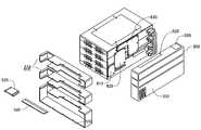
- FIG. 1is a perspective view of an exemplary modular chassis of the present invention.
- FIG. 2is the exemplary modular chassis of FIG. 1 with the covers removed.
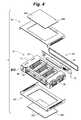
- FIG. 3is a partial exploded view of the illustration of FIG. 2 depicting the skeleton frame, the face plate, and a first electromechanical assembly according to an exemplary embodiment of the present invention.
- FIG. 4is alternate partial exploded view of the illustration of FIG. 1 illustrating the skeleton frame, the covers, the face plate and a second electromechanical assembly according to the exemplary embodiment illustrated in FIG. 3 .
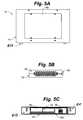
- FIG. 5depicts the front, side and top views of an embodiment of the present invention.
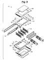
- FIG. 6is an exploded view of the modular chassis of an exemplary embodiment according to the present invention.
- FIGS. 7A , 7 B, 7 C, 7 D and 7 Eare the top view, right side view, left side view, front view and rear view respectively of an exemplary inner cover of the skeleton frame according to the exemplary embodiment of the present invention.
- FIG. 7Fis an isometric view of an exemplary inner cover according to one embodiment of the present invention.
- FIGS. 8A , 8 B, 8 C, and 8 Dare the top view, the right side view, the left side view and the front view respectively of an exemplary strut of the present invention.
- FIG. 9is a locally enlarged view of an exemplary ESD clip according to one exemplary embodiment of the present invention.
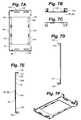
- FIGS. 10A , 10 B, 10 C, and 10 Dare the top view, front view, side view and perspective view respectively of an exemplary outer cover of the chassis according to an embodiment of the present invention.
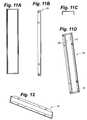
- FIGS. 11A , 11 B and 11 C and 11 Dare the front view, the top view and the side view respectively of an exemplary face-plate according to an embodiment of the present invention.
- FIG. 12is a perspective view of an electrostatic discharge (ESD) backer according to an exemplary embodiment of the present invention.
- ESDelectrostatic discharge
- FIGS. 13A , 13 B, 13 C, and 13 Dare respectively a perspective view of a rear cover, a first removable rear cover panel, a second removable rear cover panel for a single tier chassis and a rear cover for a two tier (2 U) chassis respectively according to an exemplary embodiment of the present invention.
- FIG. 14is an exploded isometric view of a stacked modular unit according to an exemplary embodiment of the present invention
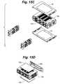
- FIGS. 15A-15Ddepict an exemplary process of assembling the stacked modular unit of FIG. 14 .
- FIG. 16is an exemplary stacked modular unit that is 4 U tall.
- FIGS. 17 and 18illustrate backplane topologies for stacked modular units according to the present invention.
- FIGS. 19-22illustrate a rear transition module configuration according to one exemplary embodiment of the present invention.
- FIG. 23illustrates an AMC module
- FIG. 24illustrates an exemplary 2 U modular unit according to an embodiment of the present invention.
- FIGS. 1 and 2are perspective views of a of modular chassis 10 providing scalable mechanical, electrical and environmental functionality for AMC, MicroTCA-specific and non-MicroTCA boards according to one embodiment of the invention.
- FIGS. 3 and 4are partial exploded views of the invention illustrated in FIGS. 1 and 2 and
- FIG. 5is a diagrammatic representation of the front, top and side views of the invention illustrated in FIGS. 1-4 .
- the chassis 10(alternatively “enclosure,” “box,” “pico-box”) generally includes a skeleton frame 15 , covers 20 , a face plate 25 and electromechanical assembly 30 mounted onto the chassis, which collectively provide the scalable mechanical, electrical and environmental functionality for AMC boards according to the present invention.
- the chassis 10is configured to receive at least one AdvancedTCA board, one or more MicroTCA specific modules such as a Power Module (PM), a MicroTCA Carrier Hub (MCH), one or more Cooling Units (CU) (i.e., a first example of a electromechanical assembly 30 of the present invention) and optionally non-MicroTCA specific modules all of which may be operably connected to a backplane (i.e., a second example of an electromechanical assembly 30 of the present invention) as will be described in the following sections.
- a Power ModulePM
- MCHMicroTCA Carrier Hub
- CUCooling Units
- FIG. 6depicts an exploded view of some of the major components of one embodiment of chassis 10 according to the present invention.
- FIGS. 7A , 7 B, 7 C, 7 D and 7 Eare the top view, right side view, left side view, front view and rear view respectively of an exemplary inner cover of the skeleton frame according to the exemplary embodiment of the present invention. As illustrated in FIG.
- skeleton frame 15preferably has a generally overall rectangular shape with a low profile and comprises an inner cover 50 removably coupled to a strut 55 by at least one fastener 60 to form an interior chamber 65 to house the AMC, MicroTCA specific and optionally non-standard cards with one or more fasteners 106 , such as for instance, a screw (not illustrated) though, in other embodiments, the inner cover 50 and strut 55 can be secured by other appropriate securing methods.
- Inner cover 50is generally rectangular sheet-like or plate-like structure with a top surface 70 and an opposing bottom surface 75 extending between a first pair of opposed substantially parallel edges 80 , 85 and a second pair of opposed substantially parallel edges 90 , 95 as best illustrated in FIGS. 6 and 7 .
- edges 80 , 85are substantially perpendicular to edges 90 , 95 .
- Extending outwardly from each edge 80 , 85 and substantially perpendicular to the top surface 70are one or more first tabs 100 .
- Inner cover 50includes a groove 105 where a portion of the surface 70 is bent away from the top surface 70 towards the bottom surface 75 to project from the bottom surface 75 in the form of a guide tab 110 .
- Guide tab 110extends substantially parallel and adjacent to edges 80 , 85 and is coplanar with tabs 100 as may be seen in FIGS. 6 and 7 .
- Guide tab 110serves to guide and locate a filter assembly within the chassis 10 as will be explained.
- Inner cover 50is provided with a first set of apertures 115 through which fasteners can be inserted.
- Each tab 100also includes a structure defining at least one hole 120 for receiving a fastener.
- the hole 120can be a through hole, a threaded hole, a blind hole or other construction to accommodate fasteners such as for instance, a screw, a nut and bolt, a rivet or other fasteners without falling outside the scope of the invention.
- a central portion of the inner cover 50is formed as an opening 125 defined by a rim 130 and having a first area extent 135 .
- structural features on inner cover 50such as the size, number and location of first tabs 100 , groove 105 , guide tab 110 , apertures 115 , hole 120 , opening 125 and rim 130 are symmetric about a plane perpendicular to the top surface 70 (and bottom surface 75 ) and parallel to edges 90 , 95 and a plane perpendicular to the top surface 70 and parallel to edges 80 , 85 .
- Edge 80 ( 85 )is provided with a plurality of attachment tabs 140 that include apertures 145 .
- Attachment tabs 140extend perpendicular to bottom surface and away from the top surface provides a point of attachment for locating and securing backplane 30 to chassis 10 as may be understood from the illustration of FIG. 4 .
- Inner cover 50can be made of any suitable material such as aluminum, steel, or other materials using a process such as metal forming, drawing or other suitable processes well known in the art. It is understood that the scope of the present invention is not limited by either the materials of construction or mode of fabrication of the constituent components of the chassis.
- Strut 55will be described with reference to FIGS. 3 , 6 and 8 .
- Strut 55is a longitudinal member of length 155 (not illustrated) extending between a beam-front end 160 and beam-rear end 165 .
- Strut 55has a I-shaped cross-section 170 extending between a strut top surface 175 and an opposed strut bottom surface 180 of height 185 (not illustrated) to form a card guide assembly best depicted in the illustration of FIGS. 8B and 8D .
- I-shaped cross-section 170has a width 189 (not illustrated) transverse to height 185 .
- Width 189has a left-side lateral surface 195 opposite a right-side lateral surface 200 best seen in the illustration of FIG. 8D .
- Lateral surfaces 190 and 195are provided with first opposed longitudinal card-guides 205 and second opposed longitudinal card-guides 206 , extending along the length 155 , disposed at a first height 215 (not illustrated) and second height 220 (not illustrated) respectively from the bottom surface 180 such that card-guides 206 are proximate the strut top surface 175 .
- Height 185is determinative of the total height of the chassis 10 and a maximum height of AMC (or other module) 225 that may be accommodated within the chassis 10 .
- Height 215 of opposed card guides 205is selected to receive and guide the AMC having a height dimension that is less than or equal to the maximum height as defined by the specification of, for instance, the AdvancedMC. 0 , MicroTCA or other related standard.
- I-shaped cross-section 170has a structure defining a plurality of cross-section apertures 230 for placing the lateral surfaces 190 and 195 in fluid communication with each other.
- Top and bottom surfaces 175 and 180are provided with attachment-apertures 235 sized and located to allow strut 55 to be mated to inner cover 50 using a fastener or other suitable fastening method to form the skeleton frame 15 as will be described in the following sections.
- FIG. 3there is shown a partial assembly of the skeleton frame 15 according to one embodiment of the present invention.
- Bottom surfaces 180 of a plurality of struts 55are fastened to the bottom surface 75 of a first inner cover 50 so that the length 155 of struts 55 is disposed parallel to the edges 90 , 95 of the inner cover 50 .
- Struts 55are disposed spaced apart to define card slot 250 between adjacent struts 55 to accommodate AMC (or other module) 225 .
- Bottom surface 75 of a second inner cover 50is fastened to the top surface 175 of struts 55 so that corresponding first tabs 100 of the first and second inner covers 50 are adjacent to each other with corresponding holes 120 on respective first tabs 100 in substantial alignment for accepting fasteners therethrough to releasably mate the first and second inner covers 50 to form the skeletal frame 15 as depicted, for example, in the illustration of FIG. 3 .
- topAs will be appreciated, the terms “top,” “bottom,” “side,” and “rear”, “right side”, “left side”, “exterior” and “interior” are exemplary only and are not intended to limit the orientation of the enclosure housing or the electronic control enclosure unless specifically referenced in a context which so indicates.
- the chassis 10includes a generally C-shaped cover 20 having a generally rectangular sheet-like or plate-like structure with a cover-top surface 270 and an opposing cover-bottom surface 275 extending between a first pair of opposed substantially parallel edges 280 , 285 and a second pair of opposed substantially parallel edges 290 , 295 .
- Projecting downwardly from edges 290 and 295are side walls 300 and 305 respectively.
- Each side wall 300 , 305has disposed on it a plurality of perforations 310 sized and shaped to allow air flow therethrough.
- Cover 20is provided with a plurality of cover-apertures 315 through which fasteners can be inserted.
- a central portion of the cover 20is formed as a cover opening 325 defined by a cover rim 330 and having a second area extent 335 (not illustrated).
- Cover opening 325has a shape that is substantially identical to the shape of opening 125 on inner cover 50 but the area 335 is proportionally larger than area 235 .
- Cover 20including the structural features associated with cover 20 , is symmetric about a plane perpendicular to the cover-top surface 270 and parallel to edges 280 , 285 as well as about a plane perpendicular to the cover-top surface 270 and parallel to edges 290 , 295 .
- cover 20is placed over inner cover 50 of the skeleton frame 15 with edges 280 , 285 , 290 and 295 of cover 20 being in substantial parallel alignment with edges 80 , 85 , 90 and 95 of inner cover 50 .
- Cover 20is shaped and dimensioned such that cover-bottom surface 27 substantially conforms to a portion of the inner cover 50 such that at least one cover-aperture 315 is in substantial alignment with hole 120 on tab 100 so that a fastener can be inserted through each corresponding cover aperture 315 and hole 120 to releaseably fasten cover 20 to inner cover 50 of skeleton frame 15 as best illustrated in FIG. 5 .
- cover opening 325is concentrically located with opening 125 with cover rim 330 disposed around and outward of rim 130 so as to form a ledge 345 extending between the two rims.
- Access panel 350depicted in FIG. 4 , is a flat sheet-like structure with a peripheral edge 360 that is shaped and dimensioned to substantially conform to the rim 330 .
- access panel 350may be supported on the ledge 345 extending between the cover-rim 330 and rim 130 on inner cover 50 so that peripheral edge 360 is located adjacent to cover rim 330 and the cover opening 325 is substantially covered.
- Access panel 350is removably fastened to the inner cover 50 using fasteners inserted through access panel apertures 365 on access panel 350 that align with suitably disposed apertures 115 on inner cover 50 when access panel 350 is located on ledge 345 .
- access panel 350encloses interior chamber 65 housing AMC and other modules according to the present invention. Upon removal of access panel 350 , access is obtained to the electrical components inside the interior chamber 65 for testing and probing the components on an AMC or other modules housed within the interior chamber 65 but without interrupting the operation of the other modules.
- skeleton frame 15including the inner covers 50 and struts 55 , the covers 20 , and backplane 30 define an enclosure with card slots 400 suitable for receiving AMC cards and other modules 410 exemplified in FIG. 23 .
- a typical AMC module 410comprises a printed circuit board 420 with a front end 425 and a rear end 430 .
- Rear end 430has a structure suitable for mating with an AMC connector 32 on backplane 30 attached to inner cover on edge 85 as seen in FIG. 4 for instance.
- Front end 425 of AMC module 410includes a face plate 440 of a standard specified height such as for example, half-height, full-height.
- AMC module 410includes side parallel edges 450 , 455 .
- AMC card 410is inserted into a card slot 400 so that edges 450 and 455 are received within card guide slots 205 ( 206 ) and progressively inserted along length 155 of chassis 10 until the rear end 430 is physically mated with AMC connector 32 .
- FIGS. 2-4depict a plurality of AMC (and optionally non-AMC modules) in a fully inserted position within chassis 10 .
- Strut 55includes a electro static discharge (ESD) clip 475 that wipes the edge 450 ( 455 ) of AMC card 410 as it is progressively slid into card guide slot 205 ( 206 ) as seen in FIGS. 8 and 9 .
- ESD clipprovides a path to chassis ground to discharge and prevent buildup of electro static discharge.
- a faceplate 25 illustrated in FIG. 11is mounted in the opening of skeleton frame 15 defined between edges 80 of inner cover 50 . Faceplate 25 has top 26 , bottom 27 and side walls 28 that provide a seal between the chassis 10 and the faceplate 440 of AMC card 410 .
- FIGS. 6 and 13illustrate a back-cover 515 that encloses the region of the chassis 10 where the backplane is attached to the chassis.
- Back-cover 515includes coverlets 520 and 525 that may be removed when interconnects (not illustrated) have to extend outside the enclosure formed by the chassis 10 .
- the chassis 10 of one embodiment of the present inventionprovides dual bays for cooling units 600 best illustrated with reference to FIG. 3 .
- the cooling unitcomprises a pair of identical fan modules 610 .
- Each fan moduleis a longitudinal chamber housing at least one fan 620 .
- One of the fansis located in a bay proximate edge 90 and serves to aspirate air into the interior chamber 65 and force it along a path substantially parallel to edges 80 ( 85 ) towards the other fan 620 which sucks the air and blows it out of the interior chamber 65 .
- a filter 630is interposed between the fan proximate edge 90 (alternatively “inlet side”).
- Filter 630is guided and located within the interior chamber 65 by guide tabs 110 illustrated in FIG. 3 .
- guide tabs 110illustrated in FIG. 3 .
- chassis unit 10can be considered a base unit or unit chassis.
- a plurality of unit chassesmay be stacked vertically, as shown in FIG. 24 for instance, to obtain a scaled, composite unit which is capable of housing diverse AMC and other modules to deliver enhanced capacity and functionality as will be described next.
- FIG. 14depicts an exploded view of a stacked configuration comprising a first unit chassis 700 and a second unit chassis 710 each of height 1 U stacked vertically to obtain a composite unit of height 2 U illustrated in FIG. 24 .
- the electromechanical assembly 30comprising the backplane 30 of each individual unit chassis 700 ( 710 ) is replaced by a second backplane 715 that is 2 U tall and is equipped with the connectors, fabric interconnects and other features needed to provide backplane functionality to each of the first and second unit chasses 700 ( 710 ).
- step 1comprises assembling first and second unit chassis 700 and 710 respectively as disclosed in the preceding sections of this disclosure. It is understood that the first step is to assemble the skeleton frames 15 of each of the unit chasses 700 and 710 . If the chasses 700 and 710 already exist, one of the covers 20 of each chassis 700 and 710 is removed and the chasses stacked vertically such that the inner cover 50 of first chassis 700 and second chassis 710 are directly in physical contact as shown in FIGS. 15A and 15B . An expander plate 725 may be used to fasten each of the chassis 700 and 710 to each other as shown in FIG.
- Covers 20are positioned and fastened to a top side 730 of unit chassis 710 and bottom side 740 of chassis 700 to form a partial composite structure 745 as shown in FIG. 15D .
- a backplane 750 of height 2 Uis attached to a rear end of the partial composite structure 745 .
- Access panels 755may be attached to covers 20 fastened to the top side 730 and bottom side 740 to complete the assembly.
- FIG. 16there is shown a staked module that is 4 U in height.
- the 4 U moduleis constructed in the manner described in the immediately preceding section but instead of stacking two chasses, four unit chassis are stacked vertically and three expander plates 725 are used to attach the chasses to each other instead of a single expander plate 725 .
- the expander plateis of a size that accommodates a stack that is more than 2 U tall. Recognizing that there may be an unutilized slot in the stack and to prevent air-flow from being diverted out of the interior enclosure 65 of the staked module, a dummy AMC card with a faceplate and AMC form factor but with no functionality is utilized to seal the slot and prevent air leaks.
- the present inventioncontemplates a AMC card form factor with a faceplate and a mechanical structure to obstruct the flow and divert it off the designed-for path.
- the multiple fan modules of the stacked modular structure and the relatively unobstructed construction of each unit chassismay be advantageously utilized to tailor the air flow through the interior enclosure 65 of the stacked modules.
- FIGS. 17 and 18depict another feature of the present invention wherein a special unit is a base unit 800 .
- interconnect panels 800 , 820 or 830are used.
- the interconnect panelis a passive interconnect in that the signals are transferred over traces that interconnect two points on different backplanes.
- the interconnect panelis an active interconnect in that the interconnect panel includes circuitry to recondition a signal in transit between two points on separate backplanes. The reconditioning can utilize signal equalization and pre-emphasis well known in the art to recondition a degraded signal.
- FIG. 18depicts three interconnect panels 810 , 820 and 830 extending and communicatively coupling points on backplanes of the second module, the third module and the fourth module in the stack to a point on the backplane of the first module.
- Back-cover 515 of height 1 Uis combined with a back-cover 532 of height 2 U to form a back-cover of height 4 U.
- Removable panels 520 and 525are absent in the interfaces between the back-covers 515 and 532 to allow the interconnect panels 810 , 820 and 830 to extend vertically between backplanes.
- unit chassis 900is configured to house AMC cards and is equipped with a backplane 30 as described in the foregoing sections.
- Unit chassis 910is configured as a rear transition module (RTM) equipped to receive a rear transition board 925 that may be a proprietary board such as for example, a single board computer (SBC).
- RTMrear transition module
- SBCsingle board computer
- Rear transition board 925is provided with probe points and test points that may be accessed through access panel 945 without interrupting the operation of the AMC modules or the rear transition board 925 .
- AMC modulesmay request and obtain resources provided on the rear transition board 925 .
- the rear transition board 925requests resources such as storage units, made available through the AMC modules housed in unit chassis 900 .
Landscapes
- Engineering & Computer Science (AREA)
- Microelectronics & Electronic Packaging (AREA)
- Cooling Or The Like Of Electrical Apparatus (AREA)
- Combinations Of Printed Boards (AREA)
Abstract
Description
Claims (19)
Priority Applications (1)
| Application Number | Priority Date | Filing Date | Title |
|---|---|---|---|
| US11/728,718US7821790B2 (en) | 2006-03-24 | 2007-03-26 | Modular chassis providing scalable mechanical, electrical and environmental functionality for MicroTCA and Advanced TCA boards |
Applications Claiming Priority (2)
| Application Number | Priority Date | Filing Date | Title |
|---|---|---|---|
| US74376106P | 2006-03-24 | 2006-03-24 | |
| US11/728,718US7821790B2 (en) | 2006-03-24 | 2007-03-26 | Modular chassis providing scalable mechanical, electrical and environmental functionality for MicroTCA and Advanced TCA boards |
Publications (2)
| Publication Number | Publication Date |
|---|---|
| US20080037218A1 US20080037218A1 (en) | 2008-02-14 |
| US7821790B2true US7821790B2 (en) | 2010-10-26 |
Family
ID=38541742
Family Applications (1)
| Application Number | Title | Priority Date | Filing Date |
|---|---|---|---|
| US11/728,718Expired - Fee RelatedUS7821790B2 (en) | 2006-03-24 | 2007-03-26 | Modular chassis providing scalable mechanical, electrical and environmental functionality for MicroTCA and Advanced TCA boards |
Country Status (2)
| Country | Link |
|---|---|
| US (1) | US7821790B2 (en) |
| WO (1) | WO2007112109A2 (en) |
Cited By (31)
| Publication number | Priority date | Publication date | Assignee | Title |
|---|---|---|---|---|
| US20080062655A1 (en)* | 2006-09-08 | 2008-03-13 | Leviton Manufacturing Co., Inc. | Equipment rack panel system and method |
| US20080181353A1 (en)* | 2007-01-31 | 2008-07-31 | Masako Ogata | Sensor Device, and Portable Communication Terminal and Electronic Device Using the Sensor Device |
| US8064200B1 (en) | 2008-04-16 | 2011-11-22 | Cyan Optics, Inc. | Cooling a chassis by moving air through a midplane between two sets of channels oriented laterally relative to one another |
| US20120057286A1 (en)* | 2008-12-12 | 2012-03-08 | Cisco Technology, Inc. | Adaptor for a router blade |
| US8155520B1 (en)* | 2008-04-16 | 2012-04-10 | Cyan, Inc. | Multi-fabric shelf for a transport network |
| US8390993B1 (en) | 2008-04-16 | 2013-03-05 | Cyan, Inc. | Light source in chassis to provide frontal illumination of a faceplate on the chassis |
| USD679668S1 (en)* | 2007-09-07 | 2013-04-09 | Leviton Manufacturing Co., Inc. | Equipment rack panel |
| US20130100613A1 (en)* | 2010-06-28 | 2013-04-25 | Nec Corporation | Fan unit, electronic device, and method for manufacturing fan unit |
| US20130184840A1 (en)* | 2012-01-12 | 2013-07-18 | Rockwell Automation Asia Pacific Business Center Pte. Ltd. | System and method for coupling an automation controller and scaleable module |
| US20130265705A1 (en)* | 2011-02-07 | 2013-10-10 | Ty Schmitt | System and method for an optimizable rack solution |
| US8576570B2 (en) | 2011-03-21 | 2013-11-05 | NCS Technologies, Inc. | Adaptive computing system with modular control, switching, and power supply architecture |
| US8582299B1 (en)* | 2010-12-23 | 2013-11-12 | Amazon Technologies, Inc. | System with movable computing devices |
| US8614890B2 (en)* | 2011-04-18 | 2013-12-24 | Hewlett-Packard Development Company, L.P. | Chassis extension module |
| US8755192B1 (en)* | 2010-03-31 | 2014-06-17 | Amazon Technologies, Inc. | Rack-mounted computer system with shock-absorbing chassis |
| US9345166B2 (en) | 2013-12-30 | 2016-05-17 | Microsoft Technology Licensing, Llc | Rackless computing equipment construction |
| US9426903B1 (en) | 2008-06-27 | 2016-08-23 | Amazon Technologies, Inc. | Cooling air stack for computer equipment |
| US9622387B1 (en) | 2010-03-31 | 2017-04-11 | Amazon Technologies, Inc. | Rack-mounted air directing device with scoop |
| US9699941B2 (en) | 2015-03-31 | 2017-07-04 | Dell Products, L.P. | Interchangeable fan support member providing lateral, structural support for server chassis |
| US9880592B2 (en) | 2015-03-30 | 2018-01-30 | Dell Products, L.P. | Modularly-constructed information handling system having perforated chassis design for receiving varying sizes of snap-in components |
| US9894808B2 (en) | 2010-03-31 | 2018-02-13 | Amazon Technologies, Inc. | Compressed air cooling system for data center |
| US9894809B1 (en) | 2013-02-28 | 2018-02-13 | Amazon Technologies, Inc. | System for supplying cooling air from sub-floor space |
| US9913394B2 (en)* | 2014-10-13 | 2018-03-06 | Fujitsu Limited | Assembly for securing at least one expansion card and server system |
| US9958911B2 (en) | 2015-03-31 | 2018-05-01 | Dell Products, L.P. | 1U to NxU expandable server chassis using interchangeable flexible covers of varying size |
| US10025357B2 (en) | 2015-06-15 | 2018-07-17 | Seagate Technology Llc | Enclosure system for computing equipment |
| US10082857B1 (en) | 2012-08-07 | 2018-09-25 | Amazon Technologies, Inc. | Cooling electrical systems based on power measurements |
| US10345873B2 (en) | 2015-03-30 | 2019-07-09 | Dell Products, L.P. | Modular hard drive receiving chassis member with vibration damping supports |
| US10405443B1 (en)* | 2018-06-11 | 2019-09-03 | Litemax Electronics Inc. | Adaptive opening for an electronic hardware enclosure |
| US10492331B1 (en) | 2010-09-29 | 2019-11-26 | Amazon Technologies, Inc. | System and method for cooling power distribution units |
| US20200073449A1 (en)* | 2016-11-17 | 2020-03-05 | Guangzhou Shiyuan Electronics Co., Ltd. | Pc module assembly |
| US20230074928A1 (en)* | 2021-09-07 | 2023-03-09 | FUDING Precision Industry (Zhengzhou) Co.,Ltd. | Electrical connector with improved heat dissipation feature |
| US20240237255A9 (en)* | 2022-10-20 | 2024-07-11 | Dell Products L.P. | Over-rack component track system for modular data centers |
Families Citing this family (43)
| Publication number | Priority date | Publication date | Assignee | Title |
|---|---|---|---|---|
| US8189599B2 (en)* | 2005-08-23 | 2012-05-29 | Rpx Corporation | Omni-protocol engine for reconfigurable bit-stream processing in high-speed networks |
| US7827442B2 (en) | 2006-01-23 | 2010-11-02 | Slt Logic Llc | Shelf management controller with hardware/software implemented dual redundant configuration |
| US7826212B2 (en)* | 2006-04-27 | 2010-11-02 | Lsi Corporation | Thermal control through a channel structure |
| US20080171569A1 (en)* | 2007-01-17 | 2008-07-17 | Pralle Chad A | Redundant wireless base stations |
| US7623356B2 (en)* | 2007-04-25 | 2009-11-24 | Hewlett-Packard Development Company, L.P. | System and method to conjoin blade modules |
| US8164906B2 (en)* | 2007-05-29 | 2012-04-24 | Michael John Franco | Modular electronic enclosure |
| US20090251867A1 (en)* | 2007-10-09 | 2009-10-08 | Sharma Viswa N | Reconfigurable, modularized fpga-based amc module |
| CN101459587B (en) | 2007-12-10 | 2012-02-15 | 华为技术有限公司 | Method and system for spreading micro telecommunication computer architecture |
| WO2009075819A1 (en)* | 2007-12-11 | 2009-06-18 | Bae Systems Information And Electronic Warfare Systems, Inc. | Apparatus for adapting mezzanine cards |
| US7843692B2 (en)* | 2008-12-30 | 2010-11-30 | Dtech Labs, Inc. | Mobile modular communication system |
| US20100217909A1 (en)* | 2009-02-24 | 2010-08-26 | Sun Microsystems, Inc. | Field replaceable unit for solid state drive system |
| TWI359352B (en)* | 2009-04-17 | 2012-03-01 | Inventec Corp | Case of sever |
| US8286009B2 (en)* | 2009-08-31 | 2012-10-09 | GE Intelligent Platforms Embedded Systems, Inc. | Computer including a carrier board and methods of assembly |
| CN102043442B (en)* | 2009-10-26 | 2014-04-23 | 鸿富锦精密工业(深圳)有限公司 | Server system and its server cabinet |
| US20110228475A1 (en)* | 2010-03-17 | 2011-09-22 | International Business Machines Corporation | Enclosure with concurrently maintainable field replaceable units |
| CN102289268A (en)* | 2010-06-17 | 2011-12-21 | 英业达股份有限公司 | rack server |
| US8385064B1 (en)* | 2010-12-07 | 2013-02-26 | Adtran, Inc. | Reversible fan module for electronic enclosures |
| US8724330B1 (en)* | 2012-12-28 | 2014-05-13 | International Business Machines Corporation | Variable latch to position a sub-chassis within a chassis |
| FR2973897B1 (en)* | 2011-04-05 | 2013-03-29 | Sagem Defense Securite | ELECTRONIC DATA PROCESSING ASSEMBLY WITH MUTUALIZED RESOURCES |
| US8797764B2 (en) | 2011-05-06 | 2014-08-05 | International Business Machines Corporation | Adjustable riser cage for varying length adapters |
| TWM422823U (en)* | 2011-09-15 | 2012-02-11 | Delta Electronics Inc | Power distribution unit and power input module compatible therewith |
| GB2506572A (en)* | 2012-07-05 | 2014-04-09 | Ibm | Blade enclosure with control and expansion canisters |
| WO2014193393A1 (en)* | 2013-05-30 | 2014-12-04 | Hewlett-Packard Development Company, L.P. | Security apparatus to house a device |
| CN105308533B (en)* | 2013-06-19 | 2019-07-30 | 桑迪士克科技有限责任公司 | A method of manufacturing an electronic assembly and an electronic assembly |
| US9898056B2 (en)* | 2013-06-19 | 2018-02-20 | Sandisk Technologies Llc | Electronic assembly with thermal channel and method of manufacture thereof |
| US10013033B2 (en)* | 2013-06-19 | 2018-07-03 | Sandisk Technologies Llc | Electronic assembly with thermal channel and method of manufacture thereof |
| US9451719B2 (en)* | 2013-08-29 | 2016-09-20 | Abb Technology Ag | U form-factor intelligent electronic device (IED) hardware platform with matching of IED wiring, from a non U form-factor IED hardware platform using adapter structure |
| US9497889B2 (en) | 2014-02-27 | 2016-11-15 | Sandisk Technologies Llc | Heat dissipation for substrate assemblies |
| US9854695B1 (en)* | 2015-09-29 | 2017-12-26 | Cisco Technology, Inc. | Single rack unit storage blade with redundant controllers |
| US10042396B1 (en)* | 2017-08-17 | 2018-08-07 | Cisco Technology, Inc. | Configurable module guides for modular electronic system |
| US10470335B2 (en) | 2017-08-17 | 2019-11-05 | Cisco Technology, Inc. | Configurable module guides for modular electronic system |
| US11557223B2 (en)* | 2018-04-19 | 2023-01-17 | Lincoln Global, Inc. | Modular and reconfigurable chassis for simulated welding training |
| US11475792B2 (en) | 2018-04-19 | 2022-10-18 | Lincoln Global, Inc. | Welding simulator with dual-user configuration |
| US12107775B2 (en)* | 2018-04-23 | 2024-10-01 | Ciena Corporation | Modular network element architecture |
| US10653022B2 (en)* | 2018-09-10 | 2020-05-12 | Caci, Inc.-Federal | Deployable hardened housing units |
| US10674620B2 (en)* | 2018-09-27 | 2020-06-02 | Cisco Technology, Inc. | Removable module adapter for modular electronic system |
| US10615831B1 (en)* | 2018-10-08 | 2020-04-07 | Rockwell Collins, Inc. | Smart mount device and system |
| CN218005217U (en)* | 2019-02-06 | 2022-12-09 | 安德鲁无线系统有限公司 | Modular Filter/Duplexer System |
| CN120406684A (en)* | 2019-07-12 | 2025-08-01 | 深圳引望智能技术有限公司 | On-vehicle computing device in smart car and smart car |
| CN111263556B (en)* | 2020-01-19 | 2023-04-11 | 中国电力科学研究院有限公司 | Skeleton texture and safety box suitable for in safety box |
| US20210235599A1 (en)* | 2020-01-29 | 2021-07-29 | Dell Products L.P. | Reversible air mover for modular processing unit |
| US12425053B2 (en) | 2020-11-09 | 2025-09-23 | Outdoor Wireless Networks LLC | Wideband modular filter/duplexer system |
| TWI855604B (en)* | 2023-03-22 | 2024-09-11 | 立端科技股份有限公司 | Replaceable cooling fan module and electronic device having the same |
Citations (75)
| Publication number | Priority date | Publication date | Assignee | Title |
|---|---|---|---|---|
| US3868158A (en)* | 1972-05-17 | 1975-02-25 | Honeywell Bull Sa | Module rack for connection boxes of printed-circuit cards |
| US3874444A (en)* | 1973-12-03 | 1975-04-01 | Gte Automatic Electric Lab Inc | Duo-baffle air separator apparatus |
| US4126269A (en)* | 1976-03-10 | 1978-11-21 | Compagnie Internationale Pour L'informatique Cii-Honeywell Bull | Ventilated enclosure |
| US4187058A (en) | 1978-06-22 | 1980-02-05 | Universal Security Instruments, Inc. | Portable air compressor |
| US4453785A (en)* | 1980-04-07 | 1984-06-12 | Smith Richard D | Modular cabinet for different video game cartridges, cassettes, and instruction booklets |
| US5031070A (en)* | 1990-06-05 | 1991-07-09 | Kai Hsu | Structure of computer housing |
| US5136464A (en)* | 1990-04-20 | 1992-08-04 | Kabushiki Kaisha Toshiba | Housing structure for housing a plurality of electric components |
| US5268637A (en) | 1991-12-16 | 1993-12-07 | Venturedyne, Ltd. | Carrier for testing circuit boards |
| US5409419A (en)* | 1992-04-08 | 1995-04-25 | Schroff Gmbh | Ventilator insert |
| US5412534A (en)* | 1993-03-20 | 1995-05-02 | International Business Machines Corporation | Modular housing |
| US5528454A (en)* | 1994-12-29 | 1996-06-18 | Compuserve Incorporated | Cooling device for electronic components arranged in a vertical series and vertical series of electronic devices containing same |
| US5557506A (en)* | 1995-03-31 | 1996-09-17 | Alantec | Expandable data processing chassis and method of assembly thereof |
| US5680294A (en)* | 1995-03-28 | 1997-10-21 | The Whitaker Corporation | Pluggable power supply for card cage |
| US5751549A (en)* | 1996-06-26 | 1998-05-12 | Sun Microsystems, Inc. | Hard disk drive assembly which has a plenum chamber and a fan assembly that is perpendicular to a rack chamber |
| US5949646A (en)* | 1998-07-31 | 1999-09-07 | Sun Microsystems, Inc. | Compact computer having a redundant air moving system and method thereof |
| US5982634A (en) | 1996-11-14 | 1999-11-09 | Systran Corporation | High speed switch package provides reduced path lengths for electrical paths through the package |
| US6166917A (en)* | 1998-01-07 | 2000-12-26 | 3Com Corporation | Techniques of assembling modular electronic equipment |
| US6181570B1 (en) | 1996-03-13 | 2001-01-30 | Siemens Nixdorf Informationssysteme Aktiengesellschaft | Electrical device module |
| US6253266B1 (en) | 1999-02-19 | 2001-06-26 | Inet Technologies, Inc. | Apparatus and method for controlling information flow in a card cage having multiple backplanes |
| US6320760B1 (en) | 1999-08-27 | 2001-11-20 | Intel Corporation | Multiple PCI card support |
| US6370605B1 (en) | 1999-03-04 | 2002-04-09 | Sun Microsystems, Inc. | Switch based scalable performance storage architecture |
| US6456498B1 (en)* | 2001-08-07 | 2002-09-24 | Hewlett-Packard Co. | CompactPCI-based computer system with mid-plane connector for equivalent front and back loading |
| US6466449B1 (en)* | 2001-08-01 | 2002-10-15 | Sun Microsystems, Inc. | Multi part disk cage apparatus |
| US6496376B1 (en)* | 2000-06-02 | 2002-12-17 | John Plunkett | Modular backplane |
| US6504717B1 (en)* | 2001-06-15 | 2003-01-07 | Cereva Networks. Inc. | Failure-tolerant high-density card rack cooling system and method |
| US6522539B2 (en)* | 2000-02-28 | 2003-02-18 | Hitachi, Ltd. | Cooling method and apparatus for an electric device |
| US20030130969A1 (en) | 2002-01-10 | 2003-07-10 | Intel Corporation | Star intelligent platform management bus topology |
| US20030152074A1 (en) | 2002-02-12 | 2003-08-14 | Hawkins Pete A. | Switched platform management architecture and related methods |
| US20030182483A1 (en) | 2002-03-08 | 2003-09-25 | Hawkins Peter A. | System management controller negotiation protocol |
| US6661673B2 (en) | 2002-02-12 | 2003-12-09 | Hewlett-Packard Development Company, L.P. | Card guide |
| US6693901B1 (en) | 2000-04-06 | 2004-02-17 | Lucent Technologies Inc. | Backplane configuration without common switch fabric |
| US6694392B1 (en)* | 2000-06-30 | 2004-02-17 | Intel Corporation | Transaction partitioning |
| US6704196B1 (en)* | 2002-07-25 | 2004-03-09 | Allied Systems Design, Inc. | Flow-through cooling in-the-round system |
| US6708372B2 (en) | 2002-05-30 | 2004-03-23 | Sun Microsystems, Inc. | Snap-in fan tray ejector and handle |
| US20040073834A1 (en) | 2002-10-10 | 2004-04-15 | Kermaani Kaamel M. | System and method for expanding the management redundancy of computer systems |
| US6795314B1 (en) | 2003-03-25 | 2004-09-21 | Hewlett-Packard Development Company, L.P. | Removable fan module and electronic device incorporating same |
| US6805560B1 (en) | 2003-09-02 | 2004-10-19 | Intel Corporation | Apparatus interconnecting circuit board and mezzanine card or cards |
| US20040264145A1 (en)* | 2003-05-08 | 2004-12-30 | Miller Greg F. | Compact electronic component system and method |
| US6900387B2 (en)* | 2002-01-30 | 2005-05-31 | Sun Microsystems, Inc. | Balanced flow cooling |
| US20050141207A1 (en) | 2003-12-30 | 2005-06-30 | Edoardo Campini | Interface enhancement for modular platform applications |
| US6934786B2 (en) | 2001-05-04 | 2005-08-23 | Rlx Technologies, Inc. | Server chassis hardware master system and method |
| US6935868B1 (en) | 2004-06-29 | 2005-08-30 | Intel Corporation | Adjustable-width, dual-connector card module |
| US6944020B2 (en)* | 2002-06-20 | 2005-09-13 | Delphi Technologies, Inc. | Computer enclosure air distribution system |
| US6968958B2 (en) | 2002-11-07 | 2005-11-29 | Hewlett-Packard Development Company, L.P. | Stackable and detachably coupled electronic device modules |
| US20050280986A1 (en)* | 2004-05-07 | 2005-12-22 | Giovanni Coglitore | Directional fan assembly |
| US20050281014A1 (en) | 2004-06-21 | 2005-12-22 | Carullo Thomas J | Surrogate card for printed circuit board assembly |
| US20060002098A1 (en) | 2001-02-28 | 2006-01-05 | Adc Telecommunications, Inc. | Telecommunications chassis and card |
| US6985967B1 (en) | 2000-07-20 | 2006-01-10 | Rlx Technologies, Inc. | Web server network system and method |
| US20060023384A1 (en) | 2004-07-28 | 2006-02-02 | Udayan Mukherjee | Systems, apparatus and methods capable of shelf management |
| US20060036793A1 (en) | 2004-08-12 | 2006-02-16 | Sandy Douglas L | Stacked 3U payload module unit |
| US20060044756A1 (en) | 2004-08-26 | 2006-03-02 | Henry Wong | Method and apparatus for cooling a module portion |
| US7013352B2 (en) | 2001-08-10 | 2006-03-14 | Sun Microsystems, Inc. | Interface standard support in modular computer systems |
| US20060114923A1 (en) | 2004-11-29 | 2006-06-01 | Overgaard Mark D | Disaggregated star platform management bus architecture system |
| US7083422B2 (en) | 2004-04-13 | 2006-08-01 | Intel Corporation | Switching system |
| US7099160B1 (en)* | 2002-10-31 | 2006-08-29 | Finisar Corporation | Card guide systems and devices |
| US7101188B1 (en) | 2005-03-30 | 2006-09-05 | Intel Corporation | Electrical edge connector adaptor |
| US20060221581A1 (en) | 2005-03-31 | 2006-10-05 | Denies Steven | Folding latching mechanism |
| US20060221559A1 (en) | 2005-03-31 | 2006-10-05 | Edoardo Campini | Two-dimensional adjustable edge connector adaptor |
| US7120739B2 (en) | 2004-04-14 | 2006-10-10 | Hitachi, Ltd. | Storage system |
| US7159062B2 (en) | 2004-01-16 | 2007-01-02 | Lucent Technologies Inc. | Electronic shelf unit with management function performed by a common shelf card with the assistance of an auxiliary interface board |
| US7172432B2 (en)* | 2005-03-31 | 2007-02-06 | Intel Corporation | Stacked multiple connection module |
| US20070038732A1 (en) | 2005-08-10 | 2007-02-15 | Neelam Chandwani | Hardware management module |
| US7200003B2 (en)* | 2004-12-23 | 2007-04-03 | Dell Products L.P. | Method and apparatus for mounting a drive in a chassis |
| US20070121306A1 (en) | 2005-11-28 | 2007-05-31 | Moakes Paul A | Monolithic backplane having a first and second portion |
| US7239509B1 (en)* | 2004-10-18 | 2007-07-03 | Matthew Roeske | Modular computer components |
| US7259961B2 (en)* | 2004-06-24 | 2007-08-21 | Intel Corporation | Reconfigurable airflow director for modular blade chassis |
| US20070217172A1 (en) | 2006-03-17 | 2007-09-20 | Steve Bisbikis | Resilient grounding clip in electronics chassis |
| US20070255430A1 (en) | 2006-01-23 | 2007-11-01 | Sharma Viswa N | Shelf management controller with hardware/software implemented dual redundant configuration |
| US7293090B1 (en) | 1999-01-15 | 2007-11-06 | Cisco Technology, Inc. | Resource management protocol for a configurable network router |
| US20080062667A1 (en) | 2006-09-08 | 2008-03-13 | Intel Corporation | Configurable Multi-faceted Input/Output Panel |
| US7370223B2 (en) | 2000-09-08 | 2008-05-06 | Goahead Software, Inc. | System and method for managing clusters containing multiple nodes |
| US7509375B2 (en) | 1999-09-16 | 2009-03-24 | Bull Sas | Management system for multimodule multiprocessor machines |
| US7516263B2 (en)* | 2006-02-27 | 2009-04-07 | Emerson Network Power - Embedded Computing, Inc. | Re-configurable PCI-Express switching device |
| US20090097200A1 (en) | 2007-04-11 | 2009-04-16 | Viswa Sharma | Modular blade for providing scalable mechanical, electrical and environmental functionality in the enterprise using advancedtca boards |
| US7603580B2 (en) | 2003-07-15 | 2009-10-13 | International Business Machines Corporation | Redundant manager for a storage system |
Family Cites Families (1)
| Publication number | Priority date | Publication date | Assignee | Title |
|---|---|---|---|---|
| US7172545B2 (en)* | 2005-03-16 | 2007-02-06 | Illinois Tool Works Inc. | Registration of intermittently moved fastener tape with continuously moving web |
- 2007
- 2007-03-26USUS11/728,718patent/US7821790B2/ennot_activeExpired - Fee Related
- 2007-03-26WOPCT/US2007/007490patent/WO2007112109A2/enactiveApplication Filing
Patent Citations (77)
| Publication number | Priority date | Publication date | Assignee | Title |
|---|---|---|---|---|
| US3868158A (en)* | 1972-05-17 | 1975-02-25 | Honeywell Bull Sa | Module rack for connection boxes of printed-circuit cards |
| US3874444A (en)* | 1973-12-03 | 1975-04-01 | Gte Automatic Electric Lab Inc | Duo-baffle air separator apparatus |
| US4126269A (en)* | 1976-03-10 | 1978-11-21 | Compagnie Internationale Pour L'informatique Cii-Honeywell Bull | Ventilated enclosure |
| US4187058A (en) | 1978-06-22 | 1980-02-05 | Universal Security Instruments, Inc. | Portable air compressor |
| US4453785A (en)* | 1980-04-07 | 1984-06-12 | Smith Richard D | Modular cabinet for different video game cartridges, cassettes, and instruction booklets |
| US5136464A (en)* | 1990-04-20 | 1992-08-04 | Kabushiki Kaisha Toshiba | Housing structure for housing a plurality of electric components |
| US5031070A (en)* | 1990-06-05 | 1991-07-09 | Kai Hsu | Structure of computer housing |
| US5268637A (en) | 1991-12-16 | 1993-12-07 | Venturedyne, Ltd. | Carrier for testing circuit boards |
| US5409419A (en)* | 1992-04-08 | 1995-04-25 | Schroff Gmbh | Ventilator insert |
| US5412534A (en)* | 1993-03-20 | 1995-05-02 | International Business Machines Corporation | Modular housing |
| US5528454A (en)* | 1994-12-29 | 1996-06-18 | Compuserve Incorporated | Cooling device for electronic components arranged in a vertical series and vertical series of electronic devices containing same |
| US5680294A (en)* | 1995-03-28 | 1997-10-21 | The Whitaker Corporation | Pluggable power supply for card cage |
| US5557506A (en)* | 1995-03-31 | 1996-09-17 | Alantec | Expandable data processing chassis and method of assembly thereof |
| US6181570B1 (en) | 1996-03-13 | 2001-01-30 | Siemens Nixdorf Informationssysteme Aktiengesellschaft | Electrical device module |
| US5751549A (en)* | 1996-06-26 | 1998-05-12 | Sun Microsystems, Inc. | Hard disk drive assembly which has a plenum chamber and a fan assembly that is perpendicular to a rack chamber |
| US5982634A (en) | 1996-11-14 | 1999-11-09 | Systran Corporation | High speed switch package provides reduced path lengths for electrical paths through the package |
| US6166917A (en)* | 1998-01-07 | 2000-12-26 | 3Com Corporation | Techniques of assembling modular electronic equipment |
| US5949646A (en)* | 1998-07-31 | 1999-09-07 | Sun Microsystems, Inc. | Compact computer having a redundant air moving system and method thereof |
| US7293090B1 (en) | 1999-01-15 | 2007-11-06 | Cisco Technology, Inc. | Resource management protocol for a configurable network router |
| US6253266B1 (en) | 1999-02-19 | 2001-06-26 | Inet Technologies, Inc. | Apparatus and method for controlling information flow in a card cage having multiple backplanes |
| US6370605B1 (en) | 1999-03-04 | 2002-04-09 | Sun Microsystems, Inc. | Switch based scalable performance storage architecture |
| US6320760B1 (en) | 1999-08-27 | 2001-11-20 | Intel Corporation | Multiple PCI card support |
| US7509375B2 (en) | 1999-09-16 | 2009-03-24 | Bull Sas | Management system for multimodule multiprocessor machines |
| US6522539B2 (en)* | 2000-02-28 | 2003-02-18 | Hitachi, Ltd. | Cooling method and apparatus for an electric device |
| US6693901B1 (en) | 2000-04-06 | 2004-02-17 | Lucent Technologies Inc. | Backplane configuration without common switch fabric |
| US6496376B1 (en)* | 2000-06-02 | 2002-12-17 | John Plunkett | Modular backplane |
| US6694392B1 (en)* | 2000-06-30 | 2004-02-17 | Intel Corporation | Transaction partitioning |
| US6985967B1 (en) | 2000-07-20 | 2006-01-10 | Rlx Technologies, Inc. | Web server network system and method |
| US7370223B2 (en) | 2000-09-08 | 2008-05-06 | Goahead Software, Inc. | System and method for managing clusters containing multiple nodes |
| US20060002098A1 (en) | 2001-02-28 | 2006-01-05 | Adc Telecommunications, Inc. | Telecommunications chassis and card |
| US7324348B2 (en)* | 2001-02-28 | 2008-01-29 | Adc Telecommunications, Inc. | Telecommunications chassis and card |
| US6934786B2 (en) | 2001-05-04 | 2005-08-23 | Rlx Technologies, Inc. | Server chassis hardware master system and method |
| US6504717B1 (en)* | 2001-06-15 | 2003-01-07 | Cereva Networks. Inc. | Failure-tolerant high-density card rack cooling system and method |
| US6466449B1 (en)* | 2001-08-01 | 2002-10-15 | Sun Microsystems, Inc. | Multi part disk cage apparatus |
| US6456498B1 (en)* | 2001-08-07 | 2002-09-24 | Hewlett-Packard Co. | CompactPCI-based computer system with mid-plane connector for equivalent front and back loading |
| US7013352B2 (en) | 2001-08-10 | 2006-03-14 | Sun Microsystems, Inc. | Interface standard support in modular computer systems |
| US20030130969A1 (en) | 2002-01-10 | 2003-07-10 | Intel Corporation | Star intelligent platform management bus topology |
| US6900387B2 (en)* | 2002-01-30 | 2005-05-31 | Sun Microsystems, Inc. | Balanced flow cooling |
| US6661673B2 (en) | 2002-02-12 | 2003-12-09 | Hewlett-Packard Development Company, L.P. | Card guide |
| US20030152074A1 (en) | 2002-02-12 | 2003-08-14 | Hawkins Pete A. | Switched platform management architecture and related methods |
| US20030182483A1 (en) | 2002-03-08 | 2003-09-25 | Hawkins Peter A. | System management controller negotiation protocol |
| US6708372B2 (en) | 2002-05-30 | 2004-03-23 | Sun Microsystems, Inc. | Snap-in fan tray ejector and handle |
| US6944020B2 (en)* | 2002-06-20 | 2005-09-13 | Delphi Technologies, Inc. | Computer enclosure air distribution system |
| US6704196B1 (en)* | 2002-07-25 | 2004-03-09 | Allied Systems Design, Inc. | Flow-through cooling in-the-round system |
| US20040073834A1 (en) | 2002-10-10 | 2004-04-15 | Kermaani Kaamel M. | System and method for expanding the management redundancy of computer systems |
| US7099160B1 (en)* | 2002-10-31 | 2006-08-29 | Finisar Corporation | Card guide systems and devices |
| US6968958B2 (en) | 2002-11-07 | 2005-11-29 | Hewlett-Packard Development Company, L.P. | Stackable and detachably coupled electronic device modules |
| US6795314B1 (en) | 2003-03-25 | 2004-09-21 | Hewlett-Packard Development Company, L.P. | Removable fan module and electronic device incorporating same |
| US20040264145A1 (en)* | 2003-05-08 | 2004-12-30 | Miller Greg F. | Compact electronic component system and method |
| US7603580B2 (en) | 2003-07-15 | 2009-10-13 | International Business Machines Corporation | Redundant manager for a storage system |
| US6805560B1 (en) | 2003-09-02 | 2004-10-19 | Intel Corporation | Apparatus interconnecting circuit board and mezzanine card or cards |
| US20050141207A1 (en) | 2003-12-30 | 2005-06-30 | Edoardo Campini | Interface enhancement for modular platform applications |
| US7159062B2 (en) | 2004-01-16 | 2007-01-02 | Lucent Technologies Inc. | Electronic shelf unit with management function performed by a common shelf card with the assistance of an auxiliary interface board |
| US7083422B2 (en) | 2004-04-13 | 2006-08-01 | Intel Corporation | Switching system |
| US7120739B2 (en) | 2004-04-14 | 2006-10-10 | Hitachi, Ltd. | Storage system |
| US20050280986A1 (en)* | 2004-05-07 | 2005-12-22 | Giovanni Coglitore | Directional fan assembly |
| US20050281014A1 (en) | 2004-06-21 | 2005-12-22 | Carullo Thomas J | Surrogate card for printed circuit board assembly |
| US7259961B2 (en)* | 2004-06-24 | 2007-08-21 | Intel Corporation | Reconfigurable airflow director for modular blade chassis |
| US6935868B1 (en) | 2004-06-29 | 2005-08-30 | Intel Corporation | Adjustable-width, dual-connector card module |
| US20060023384A1 (en) | 2004-07-28 | 2006-02-02 | Udayan Mukherjee | Systems, apparatus and methods capable of shelf management |
| US20060036793A1 (en) | 2004-08-12 | 2006-02-16 | Sandy Douglas L | Stacked 3U payload module unit |
| US20060044756A1 (en) | 2004-08-26 | 2006-03-02 | Henry Wong | Method and apparatus for cooling a module portion |
| US7239509B1 (en)* | 2004-10-18 | 2007-07-03 | Matthew Roeske | Modular computer components |
| US20060114923A1 (en) | 2004-11-29 | 2006-06-01 | Overgaard Mark D | Disaggregated star platform management bus architecture system |
| US7200003B2 (en)* | 2004-12-23 | 2007-04-03 | Dell Products L.P. | Method and apparatus for mounting a drive in a chassis |
| US7101188B1 (en) | 2005-03-30 | 2006-09-05 | Intel Corporation | Electrical edge connector adaptor |
| US20060221559A1 (en) | 2005-03-31 | 2006-10-05 | Edoardo Campini | Two-dimensional adjustable edge connector adaptor |
| US7172432B2 (en)* | 2005-03-31 | 2007-02-06 | Intel Corporation | Stacked multiple connection module |
| US20060221581A1 (en) | 2005-03-31 | 2006-10-05 | Denies Steven | Folding latching mechanism |
| US20070038732A1 (en) | 2005-08-10 | 2007-02-15 | Neelam Chandwani | Hardware management module |
| US20070121306A1 (en) | 2005-11-28 | 2007-05-31 | Moakes Paul A | Monolithic backplane having a first and second portion |
| US7388757B2 (en)* | 2005-11-28 | 2008-06-17 | Emerson Network Power - Embedded Computing, Inc. | Monolithic backplane having a first and second portion |
| US20070255430A1 (en) | 2006-01-23 | 2007-11-01 | Sharma Viswa N | Shelf management controller with hardware/software implemented dual redundant configuration |
| US7516263B2 (en)* | 2006-02-27 | 2009-04-07 | Emerson Network Power - Embedded Computing, Inc. | Re-configurable PCI-Express switching device |
| US20070217172A1 (en) | 2006-03-17 | 2007-09-20 | Steve Bisbikis | Resilient grounding clip in electronics chassis |
| US20080062667A1 (en) | 2006-09-08 | 2008-03-13 | Intel Corporation | Configurable Multi-faceted Input/Output Panel |
| US20090097200A1 (en) | 2007-04-11 | 2009-04-16 | Viswa Sharma | Modular blade for providing scalable mechanical, electrical and environmental functionality in the enterprise using advancedtca boards |
Non-Patent Citations (9)
| Title |
|---|
| Advanced MC Short Form Specification, PICMG® AMC.0 R2.0, pp. 1-56. copyright 2006. |
| Advanced Telecommunications Computing Architecture Short Form Specification PICMG, 3.0®, pp. 1-33, copyright 2003. |
| Application and File History of U.S. Appl. No. 11/626,334, filed Jan. 23, 2007, Inventors Sharma et al. |
| Application and File History of U.S. Appl. No. 12/101,739, filed Apr. 11, 2008, Inventors Sharma et al. |
| Micro Telecommunications Computing Architecture Short Form Specification, PICMG® MTCA.0 R1.0, pp. 1-34, copyright 2006. |
| PCT Patent Application No. PCT/US2007/07490; filed Mar. 26, 2007; Applicant SLT Logic LLC; Search Report dated Mar. 21, 2008. |
| PCT Patent Application No. PCT/US2007/07490; filed Mar. 26, 2007; Applicant SLT Logic LLC; Written Opinion dated Mar. 21, 2008. |
| PCT Patent Application No. PCT/US2008/004741; filed Apr. 11, 2008; Applicant SLT Logic LLC; Search Report dated Nov. 12, 2008. |
| PCT Patent Application No. PCT/US2008/004741; filed Apr. 11, 2008; Applicant SLT Logic LLC; Written Opinion dated Nov. 12, 2008. |
Cited By (51)
| Publication number | Priority date | Publication date | Assignee | Title |
|---|---|---|---|---|
| US20100314339A1 (en)* | 2006-09-08 | 2010-12-16 | Leviton Manufacturing Co., Inc. | Equipment rack panel system and method |
| US8038015B2 (en) | 2006-09-08 | 2011-10-18 | Leviton Manufacturing Co., Ltd. | Equipment rack panel system and method |
| US8061534B2 (en) | 2006-09-08 | 2011-11-22 | Leviton Manufacturing Co., Inc. | Equipment rack panel system and method |
| US20080062655A1 (en)* | 2006-09-08 | 2008-03-13 | Leviton Manufacturing Co., Inc. | Equipment rack panel system and method |
| US20080181353A1 (en)* | 2007-01-31 | 2008-07-31 | Masako Ogata | Sensor Device, and Portable Communication Terminal and Electronic Device Using the Sensor Device |
| USD679668S1 (en)* | 2007-09-07 | 2013-04-09 | Leviton Manufacturing Co., Inc. | Equipment rack panel |
| US9231875B1 (en)* | 2008-04-16 | 2016-01-05 | Ciena Corporation | Method of processing traffic in a transport network |
| US10237634B2 (en) | 2008-04-16 | 2019-03-19 | Ciena Corporation | Method of processing traffic in a node in a transport network with a network controller |
| US8390993B1 (en) | 2008-04-16 | 2013-03-05 | Cyan, Inc. | Light source in chassis to provide frontal illumination of a faceplate on the chassis |
| US8908372B1 (en) | 2008-04-16 | 2014-12-09 | Cyan, Inc. | Cooling a chassis by moving air through a midplane between two sets of channels oriented laterally relative to one another |
| US9578400B2 (en)* | 2008-04-16 | 2017-02-21 | Ciena Corporation | Network controller, a multi-fabric shelf and, a method of processing traffic in a transport network |
| US8849111B1 (en)* | 2008-04-16 | 2014-09-30 | Cyan, Inc. | Method of processing traffic in a transport network |
| US9510483B1 (en) | 2008-04-16 | 2016-11-29 | Ciena Corporation | Cooling a chassis by moving air through a midplane between two sets of channels oriented laterally relative to one another |
| US8155520B1 (en)* | 2008-04-16 | 2012-04-10 | Cyan, Inc. | Multi-fabric shelf for a transport network |
| US20160088376A1 (en)* | 2008-04-16 | 2016-03-24 | Ciena Corporation | Network controller, a multi-fabric shelf and, a method of processing traffic in a transport network |
| US8064200B1 (en) | 2008-04-16 | 2011-11-22 | Cyan Optics, Inc. | Cooling a chassis by moving air through a midplane between two sets of channels oriented laterally relative to one another |
| US9918412B2 (en) | 2008-06-27 | 2018-03-13 | Amazon Technologies, Inc. | Cooling air stack for computer equipment |
| US9426903B1 (en) | 2008-06-27 | 2016-08-23 | Amazon Technologies, Inc. | Cooling air stack for computer equipment |
| US8475214B2 (en)* | 2008-12-12 | 2013-07-02 | Cisco Technology, Inc. | Adaptor for a router blade |
| US20120057286A1 (en)* | 2008-12-12 | 2012-03-08 | Cisco Technology, Inc. | Adaptor for a router blade |
| US8755192B1 (en)* | 2010-03-31 | 2014-06-17 | Amazon Technologies, Inc. | Rack-mounted computer system with shock-absorbing chassis |
| US9622387B1 (en) | 2010-03-31 | 2017-04-11 | Amazon Technologies, Inc. | Rack-mounted air directing device with scoop |
| US9894808B2 (en) | 2010-03-31 | 2018-02-13 | Amazon Technologies, Inc. | Compressed air cooling system for data center |
| US20130100613A1 (en)* | 2010-06-28 | 2013-04-25 | Nec Corporation | Fan unit, electronic device, and method for manufacturing fan unit |
| US10492331B1 (en) | 2010-09-29 | 2019-11-26 | Amazon Technologies, Inc. | System and method for cooling power distribution units |
| US8582299B1 (en)* | 2010-12-23 | 2013-11-12 | Amazon Technologies, Inc. | System with movable computing devices |
| US9345165B1 (en) | 2010-12-23 | 2016-05-17 | Amazon Technologies, Inc. | System with movable computing devices |
| US10237998B2 (en) | 2010-12-23 | 2019-03-19 | Amazon Technologies, Inc. | System with movable computing devices |
| US8976515B2 (en)* | 2011-02-07 | 2015-03-10 | Dell Products L.P. | System and method for an optimizable rack solution |
| US20130265705A1 (en)* | 2011-02-07 | 2013-10-10 | Ty Schmitt | System and method for an optimizable rack solution |
| US9335799B2 (en) | 2011-03-21 | 2016-05-10 | NCS Technologies, Inc. | Adaptive computing system with modular control, switching, and power supply architecture |
| US8576570B2 (en) | 2011-03-21 | 2013-11-05 | NCS Technologies, Inc. | Adaptive computing system with modular control, switching, and power supply architecture |
| US8614890B2 (en)* | 2011-04-18 | 2013-12-24 | Hewlett-Packard Development Company, L.P. | Chassis extension module |
| US20130184840A1 (en)* | 2012-01-12 | 2013-07-18 | Rockwell Automation Asia Pacific Business Center Pte. Ltd. | System and method for coupling an automation controller and scaleable module |
| US9459595B2 (en)* | 2012-01-12 | 2016-10-04 | Rockwell Automation Asia Pacific Business Center Pte. Ltd. | System and method for coupling an automation controller and scaleable module |
| US10082857B1 (en) | 2012-08-07 | 2018-09-25 | Amazon Technologies, Inc. | Cooling electrical systems based on power measurements |
| US9894809B1 (en) | 2013-02-28 | 2018-02-13 | Amazon Technologies, Inc. | System for supplying cooling air from sub-floor space |
| US9345166B2 (en) | 2013-12-30 | 2016-05-17 | Microsoft Technology Licensing, Llc | Rackless computing equipment construction |
| US9913394B2 (en)* | 2014-10-13 | 2018-03-06 | Fujitsu Limited | Assembly for securing at least one expansion card and server system |
| US9880592B2 (en) | 2015-03-30 | 2018-01-30 | Dell Products, L.P. | Modularly-constructed information handling system having perforated chassis design for receiving varying sizes of snap-in components |
| US10345873B2 (en) | 2015-03-30 | 2019-07-09 | Dell Products, L.P. | Modular hard drive receiving chassis member with vibration damping supports |
| US11681337B2 (en) | 2015-03-30 | 2023-06-20 | Dell Products, L.P. | Modular hard drive receiving chassis member with vibration damping supports |
| US9699941B2 (en) | 2015-03-31 | 2017-07-04 | Dell Products, L.P. | Interchangeable fan support member providing lateral, structural support for server chassis |
| US9958911B2 (en) | 2015-03-31 | 2018-05-01 | Dell Products, L.P. | 1U to NxU expandable server chassis using interchangeable flexible covers of varying size |
| US10025357B2 (en) | 2015-06-15 | 2018-07-17 | Seagate Technology Llc | Enclosure system for computing equipment |
| US20200073449A1 (en)* | 2016-11-17 | 2020-03-05 | Guangzhou Shiyuan Electronics Co., Ltd. | Pc module assembly |
| US10990143B2 (en)* | 2016-11-17 | 2021-04-27 | Guangzhou Shiyuan Electronics Co., Ltd. | PC module assembly |
| US10405443B1 (en)* | 2018-06-11 | 2019-09-03 | Litemax Electronics Inc. | Adaptive opening for an electronic hardware enclosure |
| US20230074928A1 (en)* | 2021-09-07 | 2023-03-09 | FUDING Precision Industry (Zhengzhou) Co.,Ltd. | Electrical connector with improved heat dissipation feature |
| US12374814B2 (en)* | 2021-09-07 | 2025-07-29 | Fuding Precision Industry (Zhengzhou) Co., Ltd. | Electrical connector with improved heat dissipation feature |
| US20240237255A9 (en)* | 2022-10-20 | 2024-07-11 | Dell Products L.P. | Over-rack component track system for modular data centers |
Also Published As
| Publication number | Publication date |
|---|---|
| WO2007112109A3 (en) | 2008-07-31 |
| WO2007112109A2 (en) | 2007-10-04 |
| US20080037218A1 (en) | 2008-02-14 |
Similar Documents
| Publication | Publication Date | Title |
|---|---|---|
| US7821790B2 (en) | Modular chassis providing scalable mechanical, electrical and environmental functionality for MicroTCA and Advanced TCA boards | |
| US20090097200A1 (en) | Modular blade for providing scalable mechanical, electrical and environmental functionality in the enterprise using advancedtca boards | |
| CN101268726B (en) | Avionics bay system with quick-install enclosures and quick-install modules | |
| US8164906B2 (en) | Modular electronic enclosure | |
| US9491891B2 (en) | System and design of cost effective chassis design for networking products | |
| US9483089B2 (en) | System and method for integrating multiple servers into single full height bay of a server rack chassis | |
| US9170615B2 (en) | Compact network server or appliance | |
| CN103430120B (en) | Rack Mount Modular Compute Unit | |
| US7012815B2 (en) | Computer systems | |
| US7173817B2 (en) | Front side hot-swap chassis management module | |
| US7800894B2 (en) | Data storage device enclosures, a midplane, a method of manufacturing a midplane and modules | |
| US7606044B2 (en) | Multi-purpose structural support I/O member for a server | |
| US20040032722A1 (en) | Electronics module | |
| US6920049B2 (en) | Bladed servers | |
| US20090109619A1 (en) | Method apparatus for cooling system having an s-shaped air flow path for use in a chassis | |
| US7136283B2 (en) | Multi-computer system | |
| US20080201515A1 (en) | Method and Systems for Interfacing With PCI-Express in an Advanced Mezannine Card (AMC) Form Factor | |
| CN101639712A (en) | Server | |
| CA1242523A (en) | Modular computer system | |
| US10212842B1 (en) | Server chassis for servers | |
| CN209433362U (en) | ATX specification power supply with redundant power supply architecture | |
| US6778409B2 (en) | Component access | |
| EP2228729A1 (en) | Process to design a rear transition module RTM of an advanced telecom computing architecture ATCA board | |
| US6853552B2 (en) | Extendable computer cartridge receptacle system | |
| US6519145B1 (en) | ETSI/NEBS housing structure |
Legal Events
| Date | Code | Title | Description |
|---|---|---|---|
| AS | Assignment | Owner name:SLT LOGIC, LLC, MINNESOTA Free format text:ASSIGNMENT OF ASSIGNORS INTEREST;ASSIGNORS:CHU, WILLIAM;JAMES, ALLEN D.;TSENG, MING SIU;AND OTHERS;REEL/FRAME:019465/0198;SIGNING DATES FROM 20070612 TO 20070618 Owner name:SLT LOGIC, LLC, MINNESOTA Free format text:ASSIGNMENT OF ASSIGNORS INTEREST;ASSIGNORS:CHU, WILLIAM;JAMES, ALLEN D.;TSENG, MING SIU;AND OTHERS;SIGNING DATES FROM 20070612 TO 20070618;REEL/FRAME:019465/0198 | |
| FEPP | Fee payment procedure | Free format text:PAYOR NUMBER ASSIGNED (ORIGINAL EVENT CODE: ASPN); ENTITY STATUS OF PATENT OWNER: LARGE ENTITY Free format text:PAT HOLDER NO LONGER CLAIMS SMALL ENTITY STATUS, ENTITY STATUS SET TO UNDISCOUNTED (ORIGINAL EVENT CODE: STOL); ENTITY STATUS OF PATENT OWNER: LARGE ENTITY | |
| AS | Assignment | Owner name:RPX CORPORATION, CALIFORNIA Free format text:ASSIGNMENT OF ASSIGNORS INTEREST;ASSIGNOR:SLT LOGIC LLC;REEL/FRAME:027462/0368 Effective date:20111228 | |
| FPAY | Fee payment | Year of fee payment:4 | |
| FEPP | Fee payment procedure | Free format text:MAINTENANCE FEE REMINDER MAILED (ORIGINAL EVENT CODE: REM.) | |
| AS | Assignment | Owner name:JEFFERIES FINANCE LLC, NEW YORK Free format text:SECURITY INTEREST;ASSIGNOR:RPX CORPORATION;REEL/FRAME:046486/0433 Effective date:20180619 | |
| LAPS | Lapse for failure to pay maintenance fees | Free format text:PATENT EXPIRED FOR FAILURE TO PAY MAINTENANCE FEES (ORIGINAL EVENT CODE: EXP.); ENTITY STATUS OF PATENT OWNER: LARGE ENTITY | |
| STCH | Information on status: patent discontinuation | Free format text:PATENT EXPIRED DUE TO NONPAYMENT OF MAINTENANCE FEES UNDER 37 CFR 1.362 | |
| FP | Lapsed due to failure to pay maintenance fee | Effective date:20181026 | |
| AS | Assignment | Owner name:RPX CORPORATION, CALIFORNIA Free format text:RELEASE BY SECURED PARTY;ASSIGNOR:JEFFERIES FINANCE LLC;REEL/FRAME:054486/0422 Effective date:20201023 |