US7819869B2 - Methods of treating the sacroilac region of a patient's body - Google Patents
Methods of treating the sacroilac region of a patient's bodyDownload PDFInfo
- Publication number
- US7819869B2 US7819869B2US11/280,604US28060405AUS7819869B2US 7819869 B2US7819869 B2US 7819869B2US 28060405 AUS28060405 AUS 28060405AUS 7819869 B2US7819869 B2US 7819869B2
- Authority
- US
- United States
- Prior art keywords
- probe
- energy
- tissue
- joint
- patient
- Prior art date
- Legal status (The legal status is an assumption and is not a legal conclusion. Google has not performed a legal analysis and makes no representation as to the accuracy of the status listed.)
- Active, expires
Links
Images


Classifications
- A—HUMAN NECESSITIES
- A61—MEDICAL OR VETERINARY SCIENCE; HYGIENE
- A61B—DIAGNOSIS; SURGERY; IDENTIFICATION
- A61B18/00—Surgical instruments, devices or methods for transferring non-mechanical forms of energy to or from the body
- A61B18/04—Surgical instruments, devices or methods for transferring non-mechanical forms of energy to or from the body by heating
- A61B18/12—Surgical instruments, devices or methods for transferring non-mechanical forms of energy to or from the body by heating by passing a current through the tissue to be heated, e.g. high-frequency current
- A61B18/14—Probes or electrodes therefor
- A61B18/1482—Probes or electrodes therefor having a long rigid shaft for accessing the inner body transcutaneously in minimal invasive surgery, e.g. laparoscopy
- A—HUMAN NECESSITIES
- A61—MEDICAL OR VETERINARY SCIENCE; HYGIENE
- A61B—DIAGNOSIS; SURGERY; IDENTIFICATION
- A61B18/00—Surgical instruments, devices or methods for transferring non-mechanical forms of energy to or from the body
- A61B18/04—Surgical instruments, devices or methods for transferring non-mechanical forms of energy to or from the body by heating
- A61B18/12—Surgical instruments, devices or methods for transferring non-mechanical forms of energy to or from the body by heating by passing a current through the tissue to be heated, e.g. high-frequency current
- A61B18/14—Probes or electrodes therefor
- A61B18/148—Probes or electrodes therefor having a short, rigid shaft for accessing the inner body transcutaneously, e.g. for neurosurgery or arthroscopy
- A—HUMAN NECESSITIES
- A61—MEDICAL OR VETERINARY SCIENCE; HYGIENE
- A61B—DIAGNOSIS; SURGERY; IDENTIFICATION
- A61B18/00—Surgical instruments, devices or methods for transferring non-mechanical forms of energy to or from the body
- A61B2018/00053—Mechanical features of the instrument of device
- A61B2018/00059—Material properties
- A61B2018/00071—Electrical conductivity
- A61B2018/00083—Electrical conductivity low, i.e. electrically insulating
- A—HUMAN NECESSITIES
- A61—MEDICAL OR VETERINARY SCIENCE; HYGIENE
- A61B—DIAGNOSIS; SURGERY; IDENTIFICATION
- A61B18/00—Surgical instruments, devices or methods for transferring non-mechanical forms of energy to or from the body
- A61B2018/00053—Mechanical features of the instrument of device
- A61B2018/00184—Moving parts
- A61B2018/00196—Moving parts reciprocating lengthwise
- A—HUMAN NECESSITIES
- A61—MEDICAL OR VETERINARY SCIENCE; HYGIENE
- A61B—DIAGNOSIS; SURGERY; IDENTIFICATION
- A61B18/00—Surgical instruments, devices or methods for transferring non-mechanical forms of energy to or from the body
- A61B2018/00315—Surgical instruments, devices or methods for transferring non-mechanical forms of energy to or from the body for treatment of particular body parts
- A61B2018/00434—Neural system
- A61B2018/0044—Spinal cord
- A—HUMAN NECESSITIES
- A61—MEDICAL OR VETERINARY SCIENCE; HYGIENE
- A61B—DIAGNOSIS; SURGERY; IDENTIFICATION
- A61B18/00—Surgical instruments, devices or methods for transferring non-mechanical forms of energy to or from the body
- A61B18/04—Surgical instruments, devices or methods for transferring non-mechanical forms of energy to or from the body by heating
- A61B18/12—Surgical instruments, devices or methods for transferring non-mechanical forms of energy to or from the body by heating by passing a current through the tissue to be heated, e.g. high-frequency current
- A61B18/14—Probes or electrodes therefor
- A61B2018/1475—Electrodes retractable in or deployable from a housing
- A—HUMAN NECESSITIES
- A61—MEDICAL OR VETERINARY SCIENCE; HYGIENE
- A61B—DIAGNOSIS; SURGERY; IDENTIFICATION
- A61B18/00—Surgical instruments, devices or methods for transferring non-mechanical forms of energy to or from the body
- A61B18/04—Surgical instruments, devices or methods for transferring non-mechanical forms of energy to or from the body by heating
- A61B18/12—Surgical instruments, devices or methods for transferring non-mechanical forms of energy to or from the body by heating by passing a current through the tissue to be heated, e.g. high-frequency current
- A61B18/14—Probes or electrodes therefor
- A61B2018/1497—Electrodes covering only part of the probe circumference
Definitions
- the inventionrelates to methods of treating the sacroiliac region of a patient's body via the delivery of energy.
- Ferrante et al.Radiofrequency Sacroiliac Joint Denervation for Sacroiliac Syndrome; Regional Anaesthesia and Pain Medicine, Vol. 26, No. 2, pp. 137-142, March-April 2001, which is incorporated herein by reference
- SIposterior sacroiliac
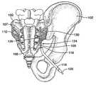
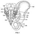
- FIG. 1is an illustration of anatomical structures in the sacroiliac region of a patient, showing the position of a probe in one embodiment of the present invention
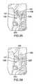
- FIGS. 2A , 2 B and 2 Care cross-sections through a typical sacroiliac joint of a patient showing the position of a probe in alternate embodiments of the present invention.
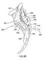
- FIGS. 3A and 3Bare illustrations of a posterior sacral foramina, showing the position of a probe in further embodiments of the present invention.
- a ‘strip lesion’refers to a lesion which is elongate, i.e. its length substantially exceeds at least one of its other two dimensions.
- a strip lesionmay be substantially straight or curved.
- ‘ablate,’ ablating or ‘ablation’is defined as: raising the temperature of a tissue such that at least a portion of the tissue is coagulated and a lesion is formed within the tissue.
- the term ‘probe’is used to describe any elongate device comprising an energy delivery device which may be percutaneously inserted into a patient's body. These devices include but are not limited to catheters, cannulae and electrosurgical probes. For the sake of clarity, the term ‘probe’ is used throughout the specification to describe any such device.
- sacroiliac syndromePain or other symptoms (described below) associated with or emanating from the sacroiliac region, including the SI joint and the surrounding region, have been referred to in the literature as sacroiliac syndrome, sacroiliac joint dysfunction or sacroiliac joint complex (SIJC) pain, amongst other terms, and, for clarity, will be referred to throughout this specification as sacroiliac joint syndrome (SIJS).
- Symptoms of sacroiliac joint syndromemay include, but are not limited to: pain, stiffness and tingling.
- proximalis used to refer to a portion or region of a device or tissue that is located closest to the user of the device.
- distalrefers to a portion or region of a device or tissue that is located closest to a treatment site or furthest away from the user.
- the SI joint 110is the joint between the sacrum 100 , a large bone at the base of the spine composed of five fused vertebrae, and the ilium 102 of the pelvis.
- SI joint 110is a relatively immobile joint, serving to absorb shock during locomotion.
- the structure of the SI joint and surrounding tissuesvaries significantly between individuals but generally comprises an articular cartilaginous surface, a ligamentous aspect and, in most cases, one or more synovial recesses.
- the nerves responsible for SI painare thought to comprise, at least in part, nerves emanating from the dorsal sacral plexus, the network of nerves on the posterior surface of the sacrum, extending from the sacral nerves 108 , also referred to as the posterior primary rami 108 , that exit the sacral foramina (posterior sacral foramen) 107 .
- the lateral branches 109branch out from the sacral nerves 108 (and branch out further along the sacrum as well) and are thought to play a role in the innervation of the SI joint.
- one broad method of treating the sacroiliac region of a patient's body by delivering energymay comprise the following steps: inserting at least one probe into the sacroiliac region, the probe comprising at least one energy delivery device; positioning the at least one energy delivery device adjacent material to be treated; and delivering energy through the at least one energy delivery device to create a longitudinal strip lesion; wherein the at least one energy delivery device remains in a static position during creation of the strip lesion.
- More specific methods of treating SIJScan be grouped into two categories: those methods that rely on access to at least a portion of the SI joint itself or the immediate vicinity and those that perform a procedure at some other location in the SI region wherein the procedure results in a reduction of SIJS symptoms associated with the SI region (these symptoms may be directly emanating from the SI region or they may have their source in the SI region but be referred to a different region of the body).
- these two approacheswill be presently described in sufficient detail so as to enable one skilled in the art to perform such procedures to treat SIJS.
- a method for the treatment of SIJS by performing a treatment procedure within or adjacent to the SI jointgenerally comprise the steps of: inserting a device into or adjacent an SI joint in a patient's body and performing a treatment operation in order to treat the SI joint and/or the surrounding region.
- the methodmay comprise the steps of: positioning at least one energy delivery device within or adjacent to a sacroiliac joint; and delivering energy through said at least one energy delivery device to create an intra-articular lesion. Energy may be delivered in various configurations and may achieve various results, as will be presently described.
- This approachis beneficial because it may allow for a treatment procedure that can effectively target neural tissue that derives from both the anterior and posterior (also referred to as ventral and dorsal) primary rami. This approach also reduces the risk of inadvertently damaging crucial neural structures, such as motor nerves or large sensory nerve trunks, since it is designed to affect only the neural structures present within or adjacent the SI joint itself.
- a first embodiment of the methodcomprises the steps of: inserting at least one elongated probe into or adjacent the SI joint and delivering energy through the probe(s), wherein the energy may be delivered in order to ablate tissue.
- Lesioning by ablationcan for example be effected using an RF signal having a voltage up to 500V, current up to 5 amps, a frequency of 100 kHz to 10 MHz and an application interval of 5 seconds to 30 minutes; for tissue in the sacroiliac region, the signal may, in some embodiments, have a voltage ranging between 10V and 100V, a frequency of 400-550 kHz, an application interval of 1 to 10 minutes, and a power of 1-20 Watts.
- a probe 120comprising a distal region 124 and a proximal region (not shown), is inserted into the intra-articular space (also referred to as the joint space) 201 of the SI joint 110 .
- probe 120may comprise an energy delivery device 126 associated with distal region 124 , and probe 120 may be operable in a monopolar configuration in conjunction with a grounding pad (not shown) placed at some location on the surface of the patient's body.
- probe 120is capable of creating a strip lesion 230 within SI joint 110 , in order to treat as much of the joint as possible within a single treatment procedure.
- a strip lesion having its longest dimension parallel to the longitudinal axis of the energy delivery devicemay have a length:width and/or length:depth ratio of approximately 3:1, i.e. the length substantially exceeds one or more of the width and/or the depth.
- another example of a strip lesionis a lesion that has its longest dimension on any axis other than an axis parallel to the longitudinal axis of the energy delivery device.
- Such a lesionmay be created substantially between two or more probes, for example in a bipolar configuration. Alternatively, such a lesion may be created by a single probe.
- the ability to create a strip lesionis not necessary and, in alternate embodiments, the probe may indeed not be required to create or even capable of creating a strip lesion. Rather, various probes, capable of producing lesions of various shapes and sizes, may also be used in conjunction with this method aspect of the present invention and the invention is not limited in this regard.
- the step of inserting at least one elongated probemay comprise penetrating into the joint using one or more rigid introducer tubes 116 or other insertional apparatus, and inserting the probe(s) through the introducer(s). Penetration into the joint may also be facilitated by the use of a sharp or pointed probe(s), by the use of a stylet, by the insertion of a guide wire or by any other insertional method or device and the invention is not limited in this regard. It should also be noted that the introducer(s) or other means for insertion may or may not be electrically and/or thermally insulated and they may be curved or straight.
- curvedis taken to refer to a deviation from the longitudinal axis of the device.
- a curved introducermay take several forms and the invention is not limited in this regard. For example, it may be curved along a substantial portion of its radius or it may have a bent tip, wherein the rest of the introducer may be straight.
- the length and diameter of the introducerare not limited to specific values and any suitably sized introducer may be used.
- introducerwill be used throughout this specification and is intended to encompass any device that may facilitate entry of the probe into a specific site within the body of a patient.
- these devicesmay be capable of penetrating into a patient's body as well as penetrating through one or more of the ligaments surrounding the SI joint.
- the probemay be positioned at the appropriate location within a patient's body without using any additional means to facilitate insertion.
- the position of the probe(s) and/or introducer(s)may be visualized and/or monitored, for example by using fluoroscopy or other imaging modalities. If fluoroscopy is used, visualization may be improved by incorporating radio-opaque markers onto one or more of the probe(s) or introducer(s). In some embodiments, radio-opaque markers may be incorporated onto a distal region of the probe(s) in order to determine the distance that the probes are extending out of the introducer(s). In addition, visual depth markers may be used to help determine the position of the probe(s) or introducer(s) within the body.
- positioningmay be confirmed by measuring the impedance of tissue at the location of the probe(s) or introducer(s), as is known in the art. In some embodiments, positioning may not be verified using these means and a user may rely in whole or in part on his or her knowledge of a patient's anatomy in order to accurately place the device(s).
- introducer 116may be inserted percutaneously about 1-3 cm below the inferior margin 204 of SI joint 110 and guided anterio-cranially until the tip 118 contacts the ilium about 1 cm above inferior margin 204 . Introducer 116 may then be manipulated until a tip of introducer 116 enters the joint space. Probe 120 may then be guided through introducer 116 until a tip of probe 120 enters intra-articular space 201 . Probe 120 may then be further advanced to traverse intra-articular space 201 of SI joint 110 . Once probe 120 is properly positioned, energy may be applied to create a strip lesion 230 within SI joint 110 . In an alternative embodiment, and with reference now to FIG.
- introducer 116may be initially manipulated so that the introducer tip 118 is placed just superior to the most posterior point of inferior margin 204 .
- Probe 120may then be guided through introducer 116 and advanced along the posterior side of the posterior margin 206 of SI joint 110 (outside the joint).
- energymay be applied to create a strip lesion 230 outside and/or within the joint (i.e. the lesion may or may not extend into the intra-articular space 201 of the joint 110 ).
- this treatment procedureillustrated in FIG.
- introducer 116is manipulated until a tip 118 of introducer 116 enters intra-articular space 201 at the most caudal point of the anterior-inferior margin 208 of SI joint 110 .
- Probe 120may then be guided through introducer 116 and along the posterior side of the anterior margin 209 of SI joint 110 (inside the joint). Once probe 120 is properly positioned, energy may be applied to create a strip lesion 230 along the anterior side of SI joint 110 .
- the introducer 116may be inserted some distance into the SI joint 110 .
- thismay be accomplished by providing, for example, a generator, operable to deliver radiofrequency (RF) energy in the range of for example about 100 kHz to about 1 GHz, connecting the generator to the probe(s) and operating the generator to deliver said RF energy to the SI joint through an energy delivery device associated with a distal region of the probe(s).
- RFradiofrequency
- a generator that may be used to perform these treatment methodsis the Pain Management Generator (PMG) from Baylis Medical Company Inc., Montreal, QC, Canada.
- PMGPain Management Generator
- the generatoris operable to deliver sufficient energy to the target tissue through the probe(s) so that tissue within or adjacent to the SI joint may be ablated, as has been defined earlier.
- the tissue ablated according to this aspect of the inventioncan include, but is not limited to, one or more of: neural tissue, whose ablation can prevent the transmission of pain sensation; structural or connective tissue, whose ablation can cause a contraction of collagen and a reduction in the volume of the intra-articular space of the joint; and vascular tissue, whose ablation may result in the disruption of nutrient supply to one or more neural structures.
- the energy delivered by the generator through the probe(s)may not ablate tissue but may perform one or more other treatment functions, such as altering the structure of collagen (without causing cellular coagulation) or globally heating the joint, thereby altering the function of neural tissue, without necessarily ablating or destroying the nerves themselves.
- the function of neural tissuemay be altered with or without ablating the neural tissue.
- Other alternative treatment functionsmay include, but are not limited to, denaturing enzymes or increasing heat shock proteins in the SI joint.
- RF (or other) energycould be delivered in a series of amplitude or frequency modulated pulses, whereby tissue heating is inhibited by interrupting periods of energy delivery with relatively long periods in which no energy is delivered.
- a voltage that is sufficiently high to affect a prolonged disruption of the function of neural tissuemay be used, while maintaining the tissue at a temperature such that no lesion will form, or such that the formation of a lesion will be inhibited.
- a generatormay not be used.
- energymay be generated by a battery or any other means (in which case the entire system [probe and energy source] may be hand-held/portable/modular) and the invention is not limited in this regard.
- any delivery of energy that may result in a treatment effect to alleviate symptoms of SIJSis intended to be included within the scope of this aspect of the present invention.
- the generatormay, in some embodiments, be releasably coupled to the probe(s). For example, this may be achieved by providing releasable electrical connectors at or close to the proximal region of the probe(s).
- the proximal region of the probe(s)may further comprise releasable connectors, such as Luer locks, to couple one or more means for cooling, such as peristaltic pumps and associated tubing, to the probe(s).
- the probe(s)may be permanently attached to the generator and/or the one or more means for cooling.
- the probe(s)may be operable to create a single strip lesion within the joint.
- the probe(s)may be operable to create such a lesion during the course of a single energy delivery step, without the need for one or more of removal of the probe(s), reinsertion of the probe(s) or intentional repositioning of the probe(s).
- the probemay remain in a substantially static position during the creation of the strip lesion. It should be noted, however, that creating strip lesions through one or more probe repositioning or energy delivery steps, as well as creating individual, non-strip lesions, also fall within the scope of this invention.
- each of these probesmay comprise one or more energy delivery devices and the invention is not limited in this regard.
- two or more probesmay be used in a bipolar configuration.
- the probesmay be spaced apart by a distance that is not greater than about five times the diameter of the energy delivery devices located on the probes. Such a spacing may be advantageous when using non-cooled probes.
- Using cooled probes, as discussed below,may allow for a larger separation distance between the probes.
- the probesmay be separated by a distance of at least about 1 cm.
- probe separationmay vary and may be more or less than the aforementioned maximum and minimum distances.
- three or more probesmay be used in a triphasic configuration. It should be noted that when more than one probe is used, the probes may be operated in a monopolar configuration and the invention is not limited in this regard. For example, several probes may be operated in a monopolar configuration, whereby a specific lesion shape may be obtained by determining an optimal spacing between probes that may produce a specific interference pattern and thus, a specific current density resulting in a desired lesion shape.
- the methodmay further comprise a step of moving the probe(s) to another location within the tissue if the user so desires.
- the probe(s)may be moved before, during, or after the step of delivering energy, and may be moved one or more times.
- the step of moving the probesmay comprise one or more of the following actions: applying a force to bend the probe within the tissue (wherein the probe may thus be described as a ‘steerable’ probe), moving the probe intact within the tissue, removing the probe intact from the tissue, re-inserting the probe into the tissue and moving one or more parts of the probe (for example, extending or retracting a segmented probe telescopically) to move the position of one or more functional elements within the tissue.
- a first embodiment of this aspect of a method of the present inventionmay be practiced as follows: a patient is made to lie prone on an operating table or similar structure, a grounding pad is placed on the surface of the patient's body and local anesthetic is provided in the area to be treated (for example, at or near the SI joint). If neural stimulation will be performed, as discussed below, the stimulation step may be performed prior to the delivery of anesthetic (if anesthetic is used).
- fluoroscopic imaging or other meansmay be used to visualize a patient's sacroiliac region in order to ascertain the desired approach for inserting the device(s) into the SI joint. This is particularly important with respect to SIJS treatment procedures because the anatomical structures involved may vary significantly from patient to patient. Various angles of approach and sites of entry may be used and the invention is not limited in this regard.
- introducer 116After introducer 116 has been inserted, the position of introducer 116 may be verified using fluoroscopic imaging (or other imaging modalities) or other means, after which probe 120 may be inserted through a bore or lumen of introducer 116 such that at least a portion of distal region 124 of probe 120 is located within or adjacent to joint 110 , depending on the specific target lesion site. It should be noted that, in those embodiments that comprise a stylet to facilitate positioning of the probe, the stylet may be located within an introducer and may be removed from the introducer prior to insertion of the probe. In some embodiments, as shown in FIG.
- probe 120is advanced far enough into joint 110 so that a strip lesion 230 will be created across a substantial part of the long axis of joint 110 when energy is delivered to energy delivery device 126 .
- Probe 120may be advanced until further advancement is impeded by an anatomical structure, such as a bone or a ligament. It may be desirable that probe 120 be inserted into joint 110 in such a way so as to minimize damage to the connective tissues of the joint, including the articular cartilage located at the surfaces of the bones, as well as the various ligaments associated with joint 110 . Therefore, in order to avoid damaging these tissues, the probe may be inserted into the cartilaginous space 207 of joint 110 , as shown in FIG.
- some embodimentsmay utilize a probe capable of creating a relatively thin strip lesion (i.e. a strip lesion with a small diameter or a strip lesion with short minor axes) so that the lesion does not extend too deeply into the cartilage.
- a usermay receive tactile feedback to indicate that the probe is contacting cartilage or ligamentous tissue and the user may then decide to retract the probe slightly and attempt to reposition the probe.
- a probemay be introduced into the SI joint without being inserted into the cartilaginous space, for example in order to reach certain nerves which may be located throughout the joint, for example as shown in FIG. 2B .
- careshould be taken to insert the probe as far as possible into joint 110 while minimizing the collateral damage to the tissues that make up the joint.
- the probemay not initially extend a large distance into the joint, in which case smaller lesions may be made while advancing the probe slowly through the joint space in order to treat as much of the joint space as possible.
- thismay be desirable if it is suspected that a fissure or other defect exists within the cartilage, in which case it may be beneficial to apply energy directly to the cartilage in order to heal the fissure or other defect.
- energymay be delivered from a generator via energy delivery device 126 to tissue of SI joint 110 .
- the probe tipmay be maneuvered into a second location within the joint and energy may again be delivered to ablate the neural tissue at the second location. This may be repeated as many times as the user wishes. If the probe is not steerable, the probe may be removed from the joint and/or the patient and the positioning and insertion steps may be repeated so that the probe is located at a second position, at which point energy may be delivered again at this location.
- the introducer and probemay be removed from the body and the patient should be allowed to recover.
- this descriptionis intended to be exemplary only and that other embodiments are envisioned as well.
- this inventionis not intended to be limited by the number and type of probes used in this and other embodiments as well as the number and type of lesions created by these probes.
- the aforementioned embodimentshave been described with reference to a typical structure of an SI joint, as can be found in the literature. However, the SI joint is known to be extremely variable and the structures discussed with respect to this preferred embodiment may not be present in some individuals or may be located in different areas of the joint. Thus, the present invention is not intended to be limited by these embodiments.
- energymay be delivered in forms other than radiofrequency electrical energy, including but not limited to: other forms of electromagnetic energy, for example microwave energy or optical energy; thermal energy; mechanical energy; and ultrasonic energy; and combinations thereof.
- the step of delivering energycould involve the use of other energy delivery devices including, but not limited to: microwave probes, optical fibers, resistive heaters, and ultrasound emitters.
- the step of delivering energy to the tissuemay involve, in some embodiments, the use of devices in which the one or more probes are actively or passively cooled. Cooling of probes can prevent the searing or coagulation of tissue directly adjacent to the probe(s) and can prevent the vaporization of liquid within the tissue. Cooling can also be used to increase the maximum lesion volume that can be formed in a given tissue.
- some embodimentsfurther comprise an additional step of measuring the temperature of tissue at least at one location. This is generally desirable so as to ensure that a given region of tissue is not exceeding a certain temperature. For example, in some embodiments it may be desirable to maintain the temperature of tissue at or below a temperature required for neural ablation.
- a means for monitoring temperaturemay be located on or within or about a distal region of the one or more probes and the temperature of tissue located proximate to the distal region(s) of the probe(s) may be monitored using the means for monitoring temperature.
- a means for monitoring temperaturemay be located at a different location on the one or more probe(s) to monitor the temperature of a region of tissue located some distance away from the distal region(s) of the probe(s).
- one or more separate means for monitoring temperaturemay be inserted into the patient's body in order to monitor the temperature of one or more specific regions of tissue.
- the means for monitoring temperaturemay take the form of one or more thermocouples, thermistors, optical thermal sensors or any other means for monitoring or sensing temperature and the invention is not limited in this regard.
- the means for monitoring temperaturemay be connected directly to the energy source (e.g. the RF generator) or they may be monitored by an independent temperature monitoring device.
- an embodiment of this methodmay further comprise one or more steps of modifying a treatment procedure in response to one or more measured parameters.
- measured parametersmay include, but are not limited to, temperature, position of the probe(s) or impedance.
- a treatment proceduremay be modified by, for example, altering the amount of energy delivered by the generator (for example, by altering the maximum allowable temperature or changing the temperature ramp rate), modifying or modulating the one or more means for cooling in some way (for example, by adjusting the rate of coolant flow), or terminating the procedure.
- the amount of energy delivered by the generatormay be modified based on the position of the one or more probes (for example, depending on the distance between a probe and the target treatment site or on the distance between the probes themselves when more than one probe is used).
- a feedback systemmay be incorporated directly into the energy source so that any modification of a treatment procedure in response to a measured parameter may occur automatically.
- there may not be an automatic feedback system in placein which case a user may manually modify a treatment procedure in response to a measured parameter.
- this inventionalso provides for a step of determining the initial parameters to be used in a treatment procedure (for example, the initial maximum power level or tissue temperature, temperature ramp rate, etc.) using information that is known about the particular SI joint to be treated. For example, if pre-treatment testing reveals specific information about the SI joint of a particular patient (this information may include, but is not limited to: joint geometry, presence or absence of synovial fluid, etc.), that information may be used to decide on what parameters to use initially for the treatment procedure.
- this informationmay include, but is not limited to: joint geometry, presence or absence of synovial fluid, etc.
- the step of performing a treatmentmay comprise the addition or removal of material to or from the joint.
- Material that may be added to the jointincludes, but is not limited to: alcohol, chemical lysing agents, pharmaceutical agents (including, but not limited to, anesthetics and other medicaments), sealants, matrix molecules such as collagen or fibrinogen, electrolyte solutions, contrast media, or any combination of the above.
- Material that may be removed from the jointincludes, but is not limited to: synovial fluid, ligamentous tissue, cartilage and any other material whose removal may help to treat the SI joint. The removal of material may be accomplished through various means, which can include aspiration, vaporization or mechanical conveyance.
- addition and removal of materialcan be performed concurrently, for example by irrigating the joint with a liquid medium while aspirating the liquid effluent from the space.
- the addition or removal of materialmay also be combined with the delivery of energy, as has described above, wherein the delivery of energy and the addition or removal of material may occur concurrently or sequentially.
- An exemplary device for removing material from a patient's bodyhas been described in co-pending U.S. patent application Ser. No. 11/128,432, filed on May 13, 2005 as well as U.S. provisional patent application 60/594,109 filed on Mar. 11, 2005. These applications are herein incorporated by reference.
- one or more probes or other devicesare placed at some location within or adjacent to the SI joint.
- the probe(s)may be inserted into any tissue within or adjacent to the joint, including, but not limited to the ligaments, cartilage or intra-articular region of the joint.
- a probemay be inserted using any approach that allows access to the joint, including but not limited to: a superior posterior approach, an inferior posterior approach, or an anterior approach.
- a probemay be inserted percutaneously using an inferior posterior approach and advanced into the SI joint through a synovial capsule 202 located at or proximate to inferior joint margin 204 .
- the probemay be operable to conform to the shape of synovial capsule 202 .
- a probe and/or introducermay be inserted into a patient's body in such a manner so that the probe and/or introducer can be positioned proximate to the posterior margin of the SI joint, with the probe oriented approximately perpendicularly to the patient's body.
- the probemay be inserted into the joint and used to create an elongate strip lesion along an anterior-posterior plane through the joint.
- this inventionis not limited to one specific approach.
- the probesmay be inserted into the joint using different approaches.
- the probesmay be inserted at a relatively higher angle (i.e. closer to an anterior-posterior plane approach) with respect to the patient's body.
- the probesmay not penetrate as far into the SI joint and may be more effective in treating the periphery of the SI joint, for example along the posterior joint line.
- itmay be useful to follow a ‘leapfrog’ approach, wherein the two probes are inserted to initial locations and a lesion is created between the probes.
- the first probeis repositioned so as to be located on the other side of the second probe, for example more cephalad (towards the head, i.e. superior) in the joint, and a second lesion is created.
- the second probeis repositioned so as to be located on the other side of the first probe, even more cephalad in the joint, and so on.
- This procedureis repeated along the long axis of the joint until a sufficient portion of the joint has been treated. Depending on the specific case, this may occur after as few as one or two lesions are created or it may require treating the entire posterior margin of the joint, including in the area of the crest of the ilium.
- This methodcan also be practiced by using a multiplicity of probes and leaving each probe in place. In other words, once a probe is in place it may remain there and further probes may be inserted in order to achieve this ‘leapfrog’ lesioning approach. In this way, an effective strip lesion may be created.
- bipolar probesmay be used in conjunction with various other approaches and this invention is not limited to using bipolar probes with this specific approach.
- the probes used during the course of a treatment proceduremay form part of the circuit of an electrical impedance meter, as is known in the art, wherein energy may be transmitted between the probes through a region of tissue, allowing a user to determine the impedance of said region of tissue.
- This featuremay be useful to determine whether or not the impedance of the tissue lies within a ‘normal’ range—if the impedance of the tissue is found to be outside that range, it may be indicative of an injury or defect within the tissue.
- a single probemay also have an impedance measuring capability, for example to help determine the location of the probe within a patient's body.
- certain embodimentsmay further comprise a step of performing a function to map the neural pathways in the tissue and this step may occur one or more times throughout the course of the procedure.
- the step of performing a function to map the neural pathways in the tissuecan involve, in some embodiments, stimulation of the neural tissue at one or more physiological stimulation frequencies and subsequent observation to determine the effect of said stimulation.
- Various frequenciesfor example, between about 1 and about 100 Hz
- voltagesfor example, between 0.1 and 5 Volts
- Observation of said stimulationcan take the form of visual, sensory, mechanical, or electrical detection of muscle activity, or the form of sensory or electrical detection of nociceptive or other sensory neural activity (e.g. temperature sensation).
- a target nerve or group of nerveshas a function that would contraindicate its ablation or functional alteration.
- the lack of a contraindicationwould lead to the step of delivering energy, whereas the presence of a contraindication would lead back to the step of inserting a probe or probes, whereby the step of inserting a probe or probes includes modifying the position of a probe or probes within the body.
- a method of this aspect of the present inventionmay comprise a step of stimulating neural tissue after a treatment procedure in order to determine the effectiveness of the treatment procedure.
- a method for the treatment of SIJS by performing a treatment procedure outside of the SI jointgenerally comprises the steps of inserting a device into a region of tissue external to the SI joint in a patient's body and performing a treatment operation in order to reduce one or more symptoms associated with SIJS.
- a treatment procedure of this method aspectmay be performed proximate to a patient's sacral region, within one or more of the SI ligaments or in a region of tissue adjacent to one or more nerves that innervate the SI joint.
- this aspect of the present inventionis intended to cover any treatment procedures performed external to the SI joint that fall within the limitations of the appended claims.
- This approachis beneficial because it may allow for a treatment procedure that can effectively target neural tissue that innervates the SI joint without having to actually enter the joint itself.
- a patient's painis emanating from the SI joint ligaments, it may be beneficial to target the neural tissue before it reaches the ligaments in order to alleviate this pain.
- energymay be delivered to connective tissue in the SI region (such as, for example, one of the sacroiliac ligaments) in order to, for example, tighten or loosen the tissue.
- connective tissue in the SI regionsuch as, for example, one of the sacroiliac ligaments
- a first embodiment of the second aspectgenerally comprises the steps of inserting one or more probes into a region of tissue in a patient's body and delivering energy through the probe(s) in order to relieve symptoms of SIJS, wherein the energy may be delivered, for example, in order to ablate tissue.
- a probe 120comprising a distal region 124 and a proximal region (not shown), is inserted proximate to sacrum 100 .
- probe 120comprises an energy delivery device 126 associated with distal region 124 , and probe 120 may be operable in a monopolar configuration in conjunction with a grounding pad (not shown) placed at some location on the surface of the patient's body.
- Probe 120may be capable of creating a strip lesion 130 adjacent sacrum 100 , in order to treat as many neural structures of the dorsal sacral plexus as possible within a single treatment procedure.
- the ability to create a strip lesionis not necessary in some embodiments. Rather, various probes, capable of producing lesions of various shapes and sizes, may also be used in conjunction with this aspect of the present invention and the invention is not limited in this regard.
- the step of inserting a device into a region of tissuemay comprise penetrating into the tissue using one or more rigid introducer tubes or other insertional apparatus, and inserting the probe(s) through the introducer(s). Penetration into the tissue may also be facilitated by the use of a sharp or pointed probe(s), by the use of a stylet, by the insertion of a guide wire or by any other insertional method or device and the invention is not limited in this regard. It should also be noted that the introducer(s) or other means for insertion may or may not be electrically and/or thermally insulated and they may be curved or straight.
- the length and diameter of the introducerare not limited to specific values and any suitably sized introducer may be used.
- the term introduceris used throughout this specification and is intended to encompass any device that may facilitate entry of the probe into a specific site within the body of a patient. In such embodiments, these devices may be capable of penetrating into a patient's body as well as penetrating through one or more of the ligaments of the sacroiliac region. In alternate embodiments, the probe may be positioned at the appropriate location within a patient's body without using any additional means to facilitate insertion.
- a supporting or stabilizing apparatus or devicemay be used to help prevent inadvertent movement of the probe(s) and/or introducer(s).
- the supporting or stabilizing apparatusi.e. a means for supporting or stabilizing
- the supporting or stabilizing apparatusmay, for example, take the form of a frame for fixing the probe(s) and/or introducer(s) in a desired position.
- the position of the probe(s) or introducer(s)may be visualized and/or monitored, for example by using fluoroscopy or other imaging modalities. If fluoroscopy is used, visualization may be improved by incorporating radio-opaque markers onto one or more of the probe(s) or introducer(s).
- radio-opaque markersmay be incorporated onto a distal region of the probe(s) in order to determine the distance that the probes are extending out of the introducer(s).
- visual depth markersmay be used to help determine the position of the probe(s) or introducer(s) within the body.
- positioningmay be confirmed by measuring the impedance of tissue at the location of the probe(s) or introducer(s), as is known in the art. In some embodiments, positioning may not be verified using these means and a user may rely in whole or in part on his knowledge of a patient's anatomy in order to accurately place the device(s).
- thismay be accomplished for example by providing a generator, operable to deliver radiofrequency (RF) energy, connecting the generator to the probe(s) and operating the generator to deliver said RF energy to the tissue through the energy delivery device associated with, for example, a distal region of the probe(s).
- the generatoris operable to deliver sufficient energy to the tissue through the probe(s) so that the tissue may be ablated, as has been defined earlier.
- the tissue ablated according to this method aspect of the inventioncan include, but is not limited to, neural tissue, whose ablation can prevent the transmission of pain sensation and vascular tissue, whose ablation may result in the disruption of nutrient supply to one or more neural structures.
- the energy delivered by the generator through the probe(s)may not ablate tissue but may perform one or more other treatment functions such as altering the structure of collagen (without causing cellular coagulation).
- RF (or other) energycould be delivered in a series of amplitude or frequency modulated pulses, whereby tissue heating is inhibited by interrupting periods of energy delivery with relatively long periods in which no energy is delivered.
- a voltage that is sufficiently high to affect a prolonged disruption of the function of neural tissuemay be used, while maintaining the tissue at a temperature such that no lesion will form, or such that the formation of a lesion will be inhibited.
- a generatormay not be used.
- energymay be generated by a battery (in which case the entire system [probe and energy source] may be hand-held/portable/modular) or any other means and the invention is not limited in this regard. Any delivery of energy that may result in a treatment effect to alleviate one or more symptoms of SIJS is intended to be included within the scope of this aspect of the present invention.
- the generatormay, in some embodiments, be releasably coupled to the probe(s). For example, this may be achieved by providing releasable electrical connectors at or proximate to the proximal region of the probe(s).
- the proximal region of the probe(s)may further comprise releasable connectors, such as Luer locks, to couple one or more means for cooling, such as peristaltic pumps and associated tubing, to the probe(s).
- the probe(s)may be permanently attached to the generator and/or the one or more means for cooling.
- the probe(s) used in this method aspect of the present inventionmay be operable to treat a plurality of neural structures without the need for one or more of removal of the probe(s), reinsertion of the probe(s) or repositioning of the probe(s).
- at least two branches of the sacral nerves 108may be treated. These two branches may comprise two or more branches of the same sacral nerve, as shown, for example, in FIGS. 3A and 3B . Alternatively, these two branches may comprise at least one lateral branch 109 from one sacral nerve and at least one lateral branch from a different sacral nerve, as shown, for example, in FIG. 1 .
- the probe(s)may be operable to create such a lesion during the course of a single energy delivery step, i.e. without the need for one or more of removal of the probe(s), reinsertion of the probe(s) or repositioning of the probe(s). It should be noted, however, that creating strip lesions through one or more probe repositioning steps, as well as creating individual, non-strip lesions, on one or more neural structures or other bodily material, also falls within the scope of this aspect of the present invention.
- this aspect of the present inventionis not limited to using only one probe and several probes may be used with this treatment method.
- each of these probesmay comprise one or more energy delivery devices and the invention is not limited in this regard.
- two or more probesmay be used in a bipolar configuration.
- the probesmay be spaced apart by a distance that is not greater than five times the diameter of the energy delivery device located on the probes.
- probe separationmay vary and may be more or less than the aforementioned maximum and minimum distances.
- three or more probesmay be used in a triphasic configuration.
- some embodimentsmay further comprise a step of moving the probe(s) to another location within the tissue if the user so desires.
- the probe(s)may be moved before, during, or after the step of delivering energy, and may be moved one or more times.
- the step of moving the probesmay comprise one or more of the following actions: applying a force to bend the probe within the tissue (wherein the probe may thus be described as a ‘steerable’ probe), moving the probe intact within the tissue, removing the probe intact from the tissue, reinserting the probe into the tissue and moving one or more parts of the probe (for example, extending or retracting a segmented probe telescopically) to move the position of one or more functional elements within the tissue.
- a method for treating SIJSmay be practiced as follows: a patient is made to lie prone on an operating table or similar structure, a grounding pad is placed on the surface of the patient's body and local anesthetic is provided. Prior to the insertion of the probe(s) or introducer(s), fluoroscopic imaging or other means may be used to visualize a patient's sacroiliac region in order to ascertain the desired approach for inserting the device(s) into the desired tissue. This is particularly important with respect to SIJS treatment procedures because the anatomical structures involved may vary significantly from patient to patient.
- a probe 120operating in a monopolar configuration, would be positioned in proximity to the posterior sacral foramina 107 , such that the step of delivering energy will result in an alteration of the function of the neural tissue of the dorsal sacral plexus. Therefore, in this embodiment, an introducer 116 may be inserted into a patient's body from a generally inferior-posterior approach under fluoroscopic guidance, such that a distal end 118 of introducer 116 is positioned proximate to or adjacent the inferior margin 101 of sacrum 100 .
- a substantially cranial-caudal or caudal-cranial approachmay be utilized, wherein introducer 116 and/or probe 120 are inserted substantially along the cranial-caudal/inferior-superior axis of the patient's body, which allows for a relatively straight-forward insertion procedure.
- introducer 116 and/or probe 120are inserted substantially along the cranial-caudal/inferior-superior axis of the patient's body, which allows for a relatively straight-forward insertion procedure.
- distal end 118 of introducer 116is positioned immediately adjacent to the bone, without any ligaments or other connective tissue in between distal end 118 and sacrum 100 .
- various angles of approach and sites of entrymay be used.
- the introducermay be either curved or straight.
- a curved introducermay take several forms and the invention is not limited in this regard. For example, it may be curved along a substantial portion of its radius or it may have a bent tip, wherein the rest of the introducer may be straight.
- the distal region 124 of probe 120may be curved or straight, as shown in FIGS. 3A and 3B .
- the position of introducer 116may be verified using fluoroscopic imaging (or other imaging modalities) or other means, after which probe 120 may be inserted through a bore or lumen of introducer 116 such that at least a portion of distal region 124 of probe 120 is located adjacent to and along sacrum 100 .
- fluoroscopic imagingor other imaging modalities
- the styletmay be located within an introducer and may be removed from the introducer prior to insertion of the probe. As shown in FIG.
- probe 120may be advanced to the extent that elongate strip lesion 130 will be created around probe 120 across a substantial part of the dorsal sacral plexus when energy is delivered to energy delivery device 126 .
- itmay be beneficial to use a flexible probe which is capable of conforming to the surface of sacrum 100 .
- the probemay extend various distances outside of the introducer and the invention is not limited in this regard. For example, if using a brush electrode comprising a plurality of electrically conductive filamentary members, an effective strip lesion may be created by dragging the probe along a tissue while supplying energy to the filaments, analogous to painting with a paint brush.
- the probemay be extended from the introducer such that a distal end of the probe may be located adjacent to the SI sacral nerve of the sacral posterior rami, so that, when the probe is retracted back into the introducer, a lesion will be created covering all of the nerves between the SI level and the location of the introducer.
- probe 120it is advisable, at this stage, to ascertain the location of probe 120 with respect to any sensory and/or motor nerves that may be located nearby by stimulating the neural tissue at one or more physiological stimulation frequencies and determining the effect of said stimulation, as will be described in more detail below.
- this stepit can be determined whether a target nerve or group of nerves has a function that would contraindicate its ablation or functional alteration.
- the lack of a contraindicationwould lead to the step of delivering energy, whereas the presence of a contraindication would lead back to the step of inserting a probe or probes, whereby the step of inserting a probe or probes comprises modifying the position of a probe or probes within the body.
- no stimulationis performed and a user may rely on his or her knowledge (for example, of the patient's anatomy) to determine whether or not to proceed with the treatment procedure.
- energymay be delivered from the generator (not shown) via energy delivery device 126 to the region of tissue located proximate to energy delivery device 126 .
- the probe tipmay be maneuvered into a second location and energy may again be delivered to ablate the neural tissue at the second location. This may be repeated as many times as the user feels is necessary.
- the insertion and positioning stepsmay be repeated so that the probe is located at a second position, at which point energy may be delivered again at this location.
- SIJS symptomsmay result from the fact that the neural tissue that may be affected by this procedure innervates the SI joint and thus, by treating the neural tissue external to the joint, pain transmission from the joint itself may be indirectly affected.
- treatment of the neural tissuemay be accomplished by the delivery of RF energy supplied to the probe(s) by a generator.
- Each probemay be furnished with one or more electrodes, and one or more probes may be used. If two or more electrodes are used, the electrodes may be in a monopolar, bipolar, multipolar, or multiphasic configuration.
- a specific lesion shapemay be obtained by determining an optimal spacing between probes that may produce a specific interference pattern and thus, a specific current density resulting in a desired lesion shape.
- Energymay be delivered to ablate at least a portion of the neural tissue of the dorsal sacral plexus, in order to reduce pain associated with the SI region.
- energymay be delivered in order to alter the function of the neural tissue of the dorsal sacral plexus, without damaging the neural tissue, for example by delivering energy in a series of amplitude or frequency modulated pulses, as described above.
- energymay be delivered in order to perform some other treatment function that may result in relief of symptoms due to SIJS.
- energymay be delivered to one or more of the sacroiliac ligaments in order to repair some defect in the ligaments or to tighten or loosen the ligaments.
- applying a treatment procedure (other than or in addition to neural ablation) external to the jointfor example, by heating one or more sacroiliac ligaments, may indirectly treat the joint itself as well (for example, by causing the shrinkage of collagen within the joint due to heat conduction from the ligaments).
- the steps of inserting one or more probes into a region of tissue in a patient's body and delivering energy through the probe(s),can be repeated one or more times, for example at each of the posterior sacral foramina as well as around the lower lumbar vertebrae.
- the steps described abovemay be used to alter the function of neural tissue around each of the posterior sacral foramina as well as the lower lumber vertebrae.
- the probe(s)may be inserted using an anterior approach, in which case the treatment procedure may involve the alteration of the function of neural tissue adjacent the anterior or posterior sacral foramina.
- energymay be delivered in forms other than radiofrequency electrical energy, including but not limited to: other forms of electromagnetic energy, for example microwave energy or optical energy; thermal energy; mechanical energy; and ultrasonic energy; and combinations thereof.
- the step of delivering energycould involve the use of other energy delivery devices including, but not limited to: microwave probes, optical fibers, resistive heaters, and ultrasound emitters.
- the step of delivering energy to the tissuemay involve, in some embodiments, the use of devices in which the one or more probes are actively or passively cooled. Cooling of probes can prevent the searing or coagulation of tissue directly adjacent to the probe(s) and can prevent the vaporization of liquid within the tissue. Cooling can also be used to increase the maximum lesion volume that can be formed in a given tissue.
- some embodimentsfurther comprise an additional step of measuring the temperature of tissue at least at one location. This is generally desirable so as to ensure that a given region of tissue is not exceeding a certain temperature. For example, in some embodiments it may be desirable to maintain the temperature of tissue at or below a temperature required for neural ablation.
- a means for monitoring temperaturemay be located on or within a distal region of the one or more probes and the temperature of tissue located proximate to the distal region(s) of the probe(s) may be monitored using the means for monitoring temperature.
- a means for monitoring temperaturemay be located at a different location on the one or more probe(s) to monitor the temperature of a region of tissue located some distance away from the distal region(s) of the probe(s).
- one or more separate means for monitoring temperaturemay be inserted into the patient's body in order to monitor the temperature of one or more specific regions of tissue.
- the means for monitoring temperaturemay take the form of one or more thermocouples, thermistors, optical thermal sensors or any other means for monitoring or sensing temperature and the invention is not limited in this regard.
- the means for monitoring temperaturemay be connected directly to the energy source (e.g. the RF generator) or they may be monitored by an independent temperature monitoring device.
- the methodmay further comprise one or more steps of modifying a treatment procedure in response to one or more measured parameters.
- measured parametersmay include, but are not limited to, temperature, position of the probe(s) or impedance, or any combination thereof.
- a treatment proceduremay be modified by, for example, altering the amount of energy delivered by the generator, modifying or modulating the one or more means for cooling in some way, or terminating the procedure, as has been described with respect to the first aspect above.
- the amount of energy delivered by the generatormay be modified based on the position of the one or more probes (for example, depending on the distance between a probe and the target treatment site or on the distance between the probes themselves when more than one probe is used).
- a feedback systemmay be incorporated directly into the energy source so that any modification of a treatment procedure in response to a measured parameter may occur automatically.
- there may not be an automatic feedback system in placein which case a user may manually modify a treatment procedure in response to a measured parameter.
- this inventionalso provides for a step of determining the initial parameters to be used in a treatment procedure (for example, the initial maximum power level or tissue temperature, temperature ramp rate, etc.) using information that is known about the particular tissue to be treated. For example, if pre-treatment testing reveals specific information about the sacrum of a particular patient (this information may include, but is not limited to: the topology of the sacrum, location of specific nerves, etc.), that information may be used to decide on what parameters to use initially for the treatment procedure.
- this informationmay include, but is not limited to: the topology of the sacrum, location of specific nerves, etc.
- the step of performing a treatment operation in order to reduce symptoms associated with SIJSmay comprise the addition or removal of material to or from the body.
- Material that may be added to the region of tissue being treatedincludes, but is not limited to, alcohol, chemical lysing agents, pharmaceutical agents (including, but not limited to, anesthetics or other medicaments) or contrast media.
- Material that may be removed from the region of tissue being treatedincludes, but is not limited to, ligamentous tissue or other connective tissue.
- the removal of materialmay be accomplished through various means, which can include aspiration or vaporization.
- the steps of addition and removal of materialcan be performed concurrently, for example by irrigating the tissue with a liquid medium while aspirating the liquid effluent.
- the addition or removal of materialmay also be combined with the delivery of energy, as has described above, wherein the delivery of energy and the addition or removal of material may occur concurrently or sequentially.
- one or more probes or other devicesare placed at some location external to the SI joint.
- the probe(s)may be inserted into various locations and the invention is not limited in this regard.
- a probemay be inserted using any approach that allows access to the desired tissue, including but not limited to: a superior posterior approach, an inferior posterior approach, or an anterior approach.
- the probesmay be inserted into the tissue using different approaches.
- the probesmay be inserted at a relatively higher angle (i.e. closer to an anterior-posterior plane approach) with respect to the patient's body.
- itmay be useful to follow a ‘leapfrog’ approach, wherein the two probes are inserted to initial locations and a lesion is created between the probes.
- the first probeis repositioned so as to be located on the other side of the second probe, for example more cephalad (towards the head) along the sacrum, and a second lesion is created.
- the second probeis repositioned so as to be located on the other side of the first probe, even more cephalad along the sacrum, and so on.
- This methodcan also be practiced by using a multiplicity of probes and leaving each probe in place. In other words, once a probe is in place it may remain there and further probes may be inserted in order to achieve this ‘leapfrog’ lesioning approach. In this way, an effective strip lesion may be created.
- bipolar probesmay be used in conjunction with various other approaches and this invention is not limited to using bipolar probes with this specific approach.
- the probes used during the course of a treatment proceduremay form part of the circuit of an electrical impedance meter, as is known in the art, wherein energy may be transmitted between the probes through a region of tissue, allowing a user to determine the impedance of said region of tissue.
- This featuremay be useful to determine whether or not the impedance of the tissue lies within a ‘normal’ range—if the impedance of the tissue is found to be outside that range, it may be indicative of an injury or defect within the tissue.
- a single probemay also have an impedance measuring capability, for example to help determine the location of the probe within a patient's body.
- Certain embodiments of the present inventionmay further comprise a step of performing a function to map the neural pathways in the tissue and this step may occur one or more times throughout the course of the procedure.
- the step of performing a function to map the neural pathways in the tissuecan involve, in some embodiments, stimulation of the neural tissue at one or more physiological stimulation frequencies and subsequent observation to determine the effect of said stimulation.
- physiological stimulation frequenciesAs is well known in the art, various frequencies and voltages can be used to stimulate both sensory and motor nerves, as has been described with respect to the first method aspect above.
- Observation of said stimulationcan take the form of visual, sensory, mechanical, or electrical detection of muscle activity, or the form of sensory or electrical detection of nociceptive or other sensory neural activity (e.g. temperature).
- a target nerve or nerveshas a function that would contraindicate its ablation or functional alteration.
- the lack of a contraindicationwould lead to the step of delivering energy, whereas the presence of a contraindication would lead back to the step of inserting a probe or probes, whereby the step of inserting a probe or probes includes modifying the position of a probe or probes within the body.
Landscapes
- Health & Medical Sciences (AREA)
- Surgery (AREA)
- Engineering & Computer Science (AREA)
- Life Sciences & Earth Sciences (AREA)
- Biomedical Technology (AREA)
- Molecular Biology (AREA)
- Nuclear Medicine, Radiotherapy & Molecular Imaging (AREA)
- Plasma & Fusion (AREA)
- Physics & Mathematics (AREA)
- Heart & Thoracic Surgery (AREA)
- Medical Informatics (AREA)
- Otolaryngology (AREA)
- Animal Behavior & Ethology (AREA)
- General Health & Medical Sciences (AREA)
- Public Health (AREA)
- Veterinary Medicine (AREA)
- Neurology (AREA)
- Neurosurgery (AREA)
- Surgical Instruments (AREA)
Abstract
Description
Claims (16)
Priority Applications (10)
| Application Number | Priority Date | Filing Date | Title |
|---|---|---|---|
| US11/280,604US7819869B2 (en) | 2004-11-15 | 2005-11-15 | Methods of treating the sacroilac region of a patient's body |
| EP06705184AEP1853184B1 (en) | 2005-02-17 | 2006-02-17 | Electrosurgical device |
| PCT/CA2006/000229WO2006086882A1 (en) | 2005-02-17 | 2006-02-17 | Electrosurgical device and method |
| US11/356,706US8951249B2 (en) | 2005-02-17 | 2006-02-17 | Electrosurgical device with discontinuous flow density |
| US11/381,783US20060259026A1 (en) | 2005-05-05 | 2006-05-05 | Electrosurgical treatment method and device |
| US11/428,458US20070156136A1 (en) | 2002-03-05 | 2006-07-03 | Methods of treating the sacroiliac region of a patient's body |
| US11/534,907US7824404B2 (en) | 2004-11-15 | 2006-09-25 | Methods of treating the sacroiliac region of a patient's body |
| US12/912,150US8864759B2 (en) | 2004-11-15 | 2010-10-26 | Methods of treating the sacroiliac region of a patient's body |
| US14/270,668US9949789B2 (en) | 2002-03-05 | 2014-05-06 | Methods of treating the sacroiliac region of a patient's body |
| US15/918,297US11291496B2 (en) | 2002-03-05 | 2018-03-12 | Methods of treating the sacroiliac region of a patient's body |
Applications Claiming Priority (7)
| Application Number | Priority Date | Filing Date | Title |
|---|---|---|---|
| US62781304P | 2004-11-15 | 2004-11-15 | |
| US59383905P | 2005-02-17 | 2005-02-17 | |
| US59478705P | 2005-05-05 | 2005-05-05 | |
| US59542605P | 2005-07-04 | 2005-07-04 | |
| US59555905P | 2005-07-14 | 2005-07-14 | |
| US59556005P | 2005-07-14 | 2005-07-14 | |
| US11/280,604US7819869B2 (en) | 2004-11-15 | 2005-11-15 | Methods of treating the sacroilac region of a patient's body |
Related Parent Applications (2)
| Application Number | Title | Priority Date | Filing Date |
|---|---|---|---|
| US11/105,524Continuation-In-PartUS7294127B2 (en) | 2002-03-05 | 2005-04-14 | Electrosurgical tissue treatment method |
| US11/105,527Continuation-In-PartUS8882755B2 (en) | 2002-03-05 | 2005-04-14 | Electrosurgical device for treatment of tissue |
Related Child Applications (4)
| Application Number | Title | Priority Date | Filing Date |
|---|---|---|---|
| US11/356,706Continuation-In-PartUS8951249B2 (en) | 2002-03-05 | 2006-02-17 | Electrosurgical device with discontinuous flow density |
| US11/381,783Continuation-In-PartUS20060259026A1 (en) | 2002-03-05 | 2006-05-05 | Electrosurgical treatment method and device |
| US11/534,907DivisionUS7824404B2 (en) | 2004-11-15 | 2006-09-25 | Methods of treating the sacroiliac region of a patient's body |
| US12/912,150DivisionUS8864759B2 (en) | 2004-11-15 | 2010-10-26 | Methods of treating the sacroiliac region of a patient's body |
Publications (2)
| Publication Number | Publication Date |
|---|---|
| US20060106376A1 US20060106376A1 (en) | 2006-05-18 |
| US7819869B2true US7819869B2 (en) | 2010-10-26 |
Family
ID=36916140
Family Applications (4)
| Application Number | Title | Priority Date | Filing Date |
|---|---|---|---|
| US11/280,604Active2027-10-14US7819869B2 (en) | 2002-03-05 | 2005-11-15 | Methods of treating the sacroilac region of a patient's body |
| US11/356,706Active2031-05-21US8951249B2 (en) | 2002-03-05 | 2006-02-17 | Electrosurgical device with discontinuous flow density |
| US11/534,907Active2027-09-03US7824404B2 (en) | 2004-11-15 | 2006-09-25 | Methods of treating the sacroiliac region of a patient's body |
| US12/912,150Active2027-01-26US8864759B2 (en) | 2004-11-15 | 2010-10-26 | Methods of treating the sacroiliac region of a patient's body |
Family Applications After (3)
| Application Number | Title | Priority Date | Filing Date |
|---|---|---|---|
| US11/356,706Active2031-05-21US8951249B2 (en) | 2002-03-05 | 2006-02-17 | Electrosurgical device with discontinuous flow density |
| US11/534,907Active2027-09-03US7824404B2 (en) | 2004-11-15 | 2006-09-25 | Methods of treating the sacroiliac region of a patient's body |
| US12/912,150Active2027-01-26US8864759B2 (en) | 2004-11-15 | 2010-10-26 | Methods of treating the sacroiliac region of a patient's body |
Country Status (3)
| Country | Link |
|---|---|
| US (4) | US7819869B2 (en) |
| EP (1) | EP1853184B1 (en) |
| WO (1) | WO2006086882A1 (en) |
Cited By (52)
| Publication number | Priority date | Publication date | Assignee | Title |
|---|---|---|---|---|
| US20070135881A1 (en)* | 2005-01-11 | 2007-06-14 | Vilims Bradley D | Combination Electrical Stimulating And Infusion Medical Device and Method |
| US20080009927A1 (en)* | 2005-01-11 | 2008-01-10 | Vilims Bradley D | Combination Electrical Stimulating and Infusion Medical Device and Method |
| US20080200972A1 (en)* | 2005-01-11 | 2008-08-21 | Rittman William J | Combination electrical stimulating and infusion medical device and method |
| US20090099613A1 (en)* | 2005-01-11 | 2009-04-16 | Vilims Bradley D | Combination electrical stimulating and infusion device and method |
| US20110144634A1 (en)* | 2005-08-02 | 2011-06-16 | Neurotherm, Inc. | Method and Apparatus for Diagnosing and Treating Neural Dysfunction |
| US20120089141A1 (en)* | 2009-06-09 | 2012-04-12 | Korea University Research And Business Foundation | Direction-controllable electrode body for selectively removing bodily tissue, and guide pipe |
| US20120203293A1 (en)* | 2004-06-08 | 2012-08-09 | Greenberg Robert J | Locating a Neural Prosthesis using Impedance and Electrode Height |
| US8361067B2 (en) | 2002-09-30 | 2013-01-29 | Relievant Medsystems, Inc. | Methods of therapeutically heating a vertebral body to treat back pain |
| US8414571B2 (en) | 2010-01-07 | 2013-04-09 | Relievant Medsystems, Inc. | Vertebral bone navigation systems |
| US8419730B2 (en) | 2008-09-26 | 2013-04-16 | Relievant Medsystems, Inc. | Systems and methods for navigating an instrument through bone |
| US8425507B2 (en) | 2002-09-30 | 2013-04-23 | Relievant Medsystems, Inc. | Basivertebral nerve denervation |
| US8808377B2 (en) | 2010-01-13 | 2014-08-19 | Jcbd, Llc | Sacroiliac joint fixation system |
| US8882764B2 (en) | 2003-03-28 | 2014-11-11 | Relievant Medsystems, Inc. | Thermal denervation devices |
| WO2016032931A1 (en) | 2014-08-26 | 2016-03-03 | Avent, Inc. | Method and system for identification of source of chronic pain and treatment |
| US9333090B2 (en) | 2010-01-13 | 2016-05-10 | Jcbd, Llc | Systems for and methods of fusing a sacroiliac joint |
| US9381045B2 (en) | 2010-01-13 | 2016-07-05 | Jcbd, Llc | Sacroiliac joint implant and sacroiliac joint instrument for fusing a sacroiliac joint |
| US9421109B2 (en) | 2010-01-13 | 2016-08-23 | Jcbd, Llc | Systems and methods of fusing a sacroiliac joint |
| US9510872B2 (en) | 2013-03-15 | 2016-12-06 | Jcbd, Llc | Spinal stabilization system |
| US9554909B2 (en) | 2012-07-20 | 2017-01-31 | Jcbd, Llc | Orthopedic anchoring system and methods |
| USRE46356E1 (en) | 2002-09-30 | 2017-04-04 | Relievant Medsystems, Inc. | Method of treating an intraosseous nerve |
| US9700356B2 (en) | 2013-07-30 | 2017-07-11 | Jcbd, Llc | Systems for and methods of fusing a sacroiliac joint |
| US9717539B2 (en) | 2013-07-30 | 2017-08-01 | Jcbd, Llc | Implants, systems, and methods for fusing a sacroiliac joint |
| US9724151B2 (en) | 2013-08-08 | 2017-08-08 | Relievant Medsystems, Inc. | Modulating nerves within bone using bone fasteners |
| US9724107B2 (en) | 2008-09-26 | 2017-08-08 | Relievant Medsystems, Inc. | Nerve modulation systems |
| US9775627B2 (en) | 2012-11-05 | 2017-10-03 | Relievant Medsystems, Inc. | Systems and methods for creating curved paths through bone and modulating nerves within the bone |
| US9788961B2 (en) | 2010-01-13 | 2017-10-17 | Jcbd, Llc | Sacroiliac joint implant system |
| US9801546B2 (en) | 2014-05-27 | 2017-10-31 | Jcbd, Llc | Systems for and methods of diagnosing and treating a sacroiliac joint disorder |
| US9826986B2 (en) | 2013-07-30 | 2017-11-28 | Jcbd, Llc | Systems for and methods of preparing a sacroiliac joint for fusion |
| WO2018067496A1 (en) | 2016-10-04 | 2018-04-12 | Avent, Inc. | Cooled rf probes |
| US10016600B2 (en) | 2013-05-30 | 2018-07-10 | Neurostim Solutions, Llc | Topical neurological stimulation |
| WO2018156160A1 (en) | 2017-02-27 | 2018-08-30 | Avent, Inc. | Method and system for improving location accuracy of a radiofrequency ablation procedure via fiducial marking |
| US10179014B1 (en) | 2012-06-01 | 2019-01-15 | Nuvasive, Inc. | Systems and methods for promoting sacroiliac joint fusion |
| US10245087B2 (en) | 2013-03-15 | 2019-04-02 | Jcbd, Llc | Systems and methods for fusing a sacroiliac joint and anchoring an orthopedic appliance |
| US10327839B2 (en) | 2010-12-30 | 2019-06-25 | Avent, Inc. | Electrosurgical apparatus having a sensor |
| US10390877B2 (en) | 2011-12-30 | 2019-08-27 | Relievant Medsystems, Inc. | Systems and methods for treating back pain |
| WO2019183624A1 (en) | 2018-03-23 | 2019-09-26 | Avent, Inc. | System and method for controlling energy delivered to an area of tissue during a treatment procedure |
| US10588691B2 (en) | 2012-09-12 | 2020-03-17 | Relievant Medsystems, Inc. | Radiofrequency ablation of tissue within a vertebral body |
| US10603055B2 (en) | 2017-09-15 | 2020-03-31 | Jcbd, Llc | Systems for and methods of preparing and fusing a sacroiliac joint |
| US10716618B2 (en) | 2010-05-21 | 2020-07-21 | Stratus Medical, LLC | Systems and methods for tissue ablation |
| US10736688B2 (en) | 2009-11-05 | 2020-08-11 | Stratus Medical, LLC | Methods and systems for spinal radio frequency neurotomy |
| US10786300B2 (en) | 2015-04-13 | 2020-09-29 | Carlos Fernando Bazoberry | Radiofrequency denervation needle and method |
| US10953225B2 (en) | 2017-11-07 | 2021-03-23 | Neurostim Oab, Inc. | Non-invasive nerve activator with adaptive circuit |
| US11007010B2 (en) | 2019-09-12 | 2021-05-18 | Relevant Medsysterns, Inc. | Curved bone access systems |
| US11077301B2 (en) | 2015-02-21 | 2021-08-03 | NeurostimOAB, Inc. | Topical nerve stimulator and sensor for bladder control |
| US11229789B2 (en) | 2013-05-30 | 2022-01-25 | Neurostim Oab, Inc. | Neuro activator with controller |
| US11458311B2 (en) | 2019-06-26 | 2022-10-04 | Neurostim Technologies Llc | Non-invasive nerve activator patch with adaptive circuit |
| US11730958B2 (en) | 2019-12-16 | 2023-08-22 | Neurostim Solutions, Llc | Non-invasive nerve activator with boosted charge delivery |
| US12016615B2 (en) | 2015-08-28 | 2024-06-25 | Avent, Inc. | Liquid delivery method for cooled RF system |
| US12039731B2 (en) | 2020-12-22 | 2024-07-16 | Relievant Medsystems, Inc. | Prediction of candidates for spinal neuromodulation |
| US12035961B2 (en) | 2015-04-13 | 2024-07-16 | Carlos Fernando Bazoberry | Radiofrequency denervation needle and method |
| US12082876B1 (en) | 2020-09-28 | 2024-09-10 | Relievant Medsystems, Inc. | Introducer drill |
| US12433668B1 (en) | 2021-11-08 | 2025-10-07 | Relievant Medsystems, Inc. | Impedance stoppage mitigation during radiofrequency tissue ablation procedures |
Families Citing this family (81)
| Publication number | Priority date | Publication date | Assignee | Title |
|---|---|---|---|---|
| ES2306706T3 (en) | 2000-03-06 | 2008-11-16 | Salient Surgical Technologies, Inc. | FLUID SUPPLY SYSTEM AND CONTROLLER FOR ELECTROCHURGICAL DEVICES. |
| US6689131B2 (en) | 2001-03-08 | 2004-02-10 | Tissuelink Medical, Inc. | Electrosurgical device having a tissue reduction sensor |
| US6558385B1 (en) | 2000-09-22 | 2003-05-06 | Tissuelink Medical, Inc. | Fluid-assisted medical device |
| US8048070B2 (en) | 2000-03-06 | 2011-11-01 | Salient Surgical Technologies, Inc. | Fluid-assisted medical devices, systems and methods |
| US6953461B2 (en) | 2002-05-16 | 2005-10-11 | Tissuelink Medical, Inc. | Fluid-assisted medical devices, systems and methods |
| US7811282B2 (en) | 2000-03-06 | 2010-10-12 | Salient Surgical Technologies, Inc. | Fluid-assisted electrosurgical devices, electrosurgical unit with pump and methods of use thereof |
| AU2002357166A1 (en) | 2001-12-12 | 2003-06-23 | Tissuelink Medical, Inc. | Fluid-assisted medical devices, systems and methods |
| US7144468B2 (en)* | 2002-09-05 | 2006-12-05 | Metglas, Inc. | Method of constructing a unitary amorphous metal component for an electric machine |
| WO2004039416A2 (en) | 2002-10-29 | 2004-05-13 | Tissuelink Medical, Inc. | Fluid-assisted electrosurgical scissors and methods |
| US7727232B1 (en) | 2004-02-04 | 2010-06-01 | Salient Surgical Technologies, Inc. | Fluid-assisted medical devices and methods |
| US20060036251A1 (en) | 2004-08-09 | 2006-02-16 | Reiley Mark A | Systems and methods for the fixation or fusion of bone |
| US8425570B2 (en) | 2004-08-09 | 2013-04-23 | Si-Bone Inc. | Apparatus, systems, and methods for achieving anterior lumbar interbody fusion |
| US20070156241A1 (en) | 2004-08-09 | 2007-07-05 | Reiley Mark A | Systems and methods for the fixation or fusion of bone |
| US20180228621A1 (en) | 2004-08-09 | 2018-08-16 | Mark A. Reiley | Apparatus, systems, and methods for the fixation or fusion of bone |
| US8470004B2 (en) | 2004-08-09 | 2013-06-25 | Si-Bone Inc. | Apparatus, systems, and methods for stabilizing a spondylolisthesis |
| US8388667B2 (en) | 2004-08-09 | 2013-03-05 | Si-Bone, Inc. | Systems and methods for the fixation or fusion of bone using compressive implants |
| US9949843B2 (en) | 2004-08-09 | 2018-04-24 | Si-Bone Inc. | Apparatus, systems, and methods for the fixation or fusion of bone |
| US9662158B2 (en)* | 2004-08-09 | 2017-05-30 | Si-Bone Inc. | Systems and methods for the fixation or fusion of bone at or near a sacroiliac joint |
| US8414648B2 (en)* | 2004-08-09 | 2013-04-09 | Si-Bone Inc. | Apparatus, systems, and methods for achieving trans-iliac lumbar fusion |
| US8444693B2 (en)* | 2004-08-09 | 2013-05-21 | Si-Bone Inc. | Apparatus, systems, and methods for achieving lumbar facet fusion |
| US7386350B2 (en)* | 2005-01-11 | 2008-06-10 | Vilims Bradley D | Combination electrical stimulating and infusion medical device |
| US20080287783A1 (en)* | 2007-05-16 | 2008-11-20 | General Electric Company | System and method of tracking delivery of an imaging probe |
| US7976469B2 (en) | 2007-06-04 | 2011-07-12 | Medtronic, Inc. | Percutaneous needle guide |
| US7938834B2 (en)* | 2007-07-13 | 2011-05-10 | Thomas F Roush | Hybrid fusion/arthroplasty device |
| WO2009065061A1 (en) | 2007-11-14 | 2009-05-22 | Myoscience, Inc. | Pain management using cryogenic remodeling |
| US20090149797A1 (en)* | 2007-12-05 | 2009-06-11 | Searete Llc, A Limited Liability Corporation Of The State Of Delaware | System for reversible chemical modulation of neural activity |
| US20090149799A1 (en)* | 2007-12-05 | 2009-06-11 | Searete Llc, A Limited Liability Corporation Of The State Of Delaware | Method for chemical modulation of neural activity |
| US8195287B2 (en) | 2007-12-05 | 2012-06-05 | The Invention Science Fund I, Llc | Method for electrical modulation of neural conduction |
| US8165669B2 (en)* | 2007-12-05 | 2012-04-24 | The Invention Science Fund I, Llc | System for magnetic modulation of neural conduction |
| US8170660B2 (en)* | 2007-12-05 | 2012-05-01 | The Invention Science Fund I, Llc | System for thermal modulation of neural activity |
| US8180446B2 (en) | 2007-12-05 | 2012-05-15 | The Invention Science Fund I, Llc | Method and system for cyclical neural modulation based on activity state |
| US8170658B2 (en)* | 2007-12-05 | 2012-05-01 | The Invention Science Fund I, Llc | System for electrical modulation of neural conduction |
| US8165668B2 (en)* | 2007-12-05 | 2012-04-24 | The Invention Science Fund I, Llc | Method for magnetic modulation of neural conduction |
| US8180447B2 (en) | 2007-12-05 | 2012-05-15 | The Invention Science Fund I, Llc | Method for reversible chemical modulation of neural activity |
| US8160695B2 (en)* | 2007-12-05 | 2012-04-17 | The Invention Science Fund I, Llc | System for chemical modulation of neural activity |
| US8364277B2 (en)* | 2008-01-10 | 2013-01-29 | Bioness Inc. | Methods and apparatus for implanting electronic implants within the body |
| GB0809461D0 (en)* | 2008-05-23 | 2008-07-02 | Gyrus Medical Ltd | An electrosurgical generator and system |
| US8298226B2 (en) | 2008-05-23 | 2012-10-30 | Gyrus Medical Limited | Electrosurgical generator and system |
| US8398627B2 (en) | 2008-05-23 | 2013-03-19 | Gyrus Medical Limited | Electrosurgical generator and system |
| US8494650B2 (en)* | 2008-08-07 | 2013-07-23 | Bioness, Inc. | Insertion tools and methods for an electrical stimulation implant |
| US20100286687A1 (en)* | 2009-05-06 | 2010-11-11 | Ian Feldberg | Dual Energy Therapy Needle |
| EP2563256B1 (en) | 2010-04-26 | 2019-08-28 | Medtronic Holding Company Sàrl | Electrosurgical device |
| US12076074B2 (en) | 2010-04-26 | 2024-09-03 | Medtronic Holding Company Sàrl | Electrosurgical device and methods |
| US12409039B2 (en)* | 2010-07-27 | 2025-09-09 | Tenon Medical, Inc. | Systems for sacroiliac joint stabilization |
| US9113972B2 (en) | 2011-08-24 | 2015-08-25 | Pioneer Surgical Technology, Inc. | Apparatus and methods for immobilization and fusion of a synovial joint |
| US9044321B2 (en) | 2012-03-09 | 2015-06-02 | Si-Bone Inc. | Integrated implant |
| US8778026B2 (en) | 2012-03-09 | 2014-07-15 | Si-Bone Inc. | Artificial SI joint |
| US10363140B2 (en) | 2012-03-09 | 2019-07-30 | Si-Bone Inc. | Systems, device, and methods for joint fusion |
| EP3818947B1 (en) | 2012-05-04 | 2023-08-30 | SI-Bone, Inc. | Fenestrated implant |
| US9877707B2 (en) | 2013-03-07 | 2018-01-30 | Kyphon SÀRL | Systems and methods for track coagulation |
| WO2014145902A1 (en) | 2013-03-15 | 2014-09-18 | Si-Bone Inc. | Implants for spinal fixation or fusion |
| CN105377128B (en) | 2013-03-15 | 2019-02-22 | 9234438加拿大股份有限公司 | Electrosurgical mapping tools and methods |
| CN104178975B (en)* | 2013-05-22 | 2018-02-16 | 青岛海尔洗衣机有限公司 | The automatic washing machine and its method for launching additive |
| US9925001B2 (en)* | 2013-07-19 | 2018-03-27 | Boston Scientific Scimed, Inc. | Spiral bipolar electrode renal denervation balloon |
| US9839448B2 (en)* | 2013-10-15 | 2017-12-12 | Si-Bone Inc. | Implant placement |
| US11147688B2 (en) | 2013-10-15 | 2021-10-19 | Si-Bone Inc. | Implant placement |
| EP3110324A4 (en)* | 2014-02-28 | 2017-10-18 | Powell Mansfield, Inc. | Systems, methods and devices for sensing emg activity |
| US10166033B2 (en) | 2014-09-18 | 2019-01-01 | Si-Bone Inc. | Implants for bone fixation or fusion |
| JP6542362B2 (en) | 2014-09-18 | 2019-07-10 | エスアイ−ボーン・インコーポレイテッドSi−Bone, Inc. | Matrix implant |
| US10376206B2 (en) | 2015-04-01 | 2019-08-13 | Si-Bone Inc. | Neuromonitoring systems and methods for bone fixation or fusion procedures |
| US20170258352A1 (en)* | 2015-10-07 | 2017-09-14 | Synaptive Medical (Barbados) Inc. | Improved methods and apparatus for cortical stimulation mapping during surgical procedures |
| US11318310B1 (en) | 2015-10-26 | 2022-05-03 | Nevro Corp. | Neuromodulation for altering autonomic functions, and associated systems and methods |
| US20170119461A1 (en)* | 2015-10-29 | 2017-05-04 | Kyphon Sárl | Electrosurgical Apparatus with Temperature Sensing and Methods of use thereof |
| US10441339B2 (en) | 2015-11-17 | 2019-10-15 | Medtronic Holding Company Sárl | Spinal tissue ablation apparatus, system, and method |
| GB2564392A (en)* | 2017-07-05 | 2019-01-16 | Creo Medical Ltd | Apparatus and methods for thermally treating ligaments |
| WO2019051260A1 (en) | 2017-09-08 | 2019-03-14 | Pioneer Surgical Technology, Inc. | Intervertebral implants, instruments, and methods |
| US11116519B2 (en) | 2017-09-26 | 2021-09-14 | Si-Bone Inc. | Systems and methods for decorticating the sacroiliac joint |
| USD907771S1 (en) | 2017-10-09 | 2021-01-12 | Pioneer Surgical Technology, Inc. | Intervertebral implant |
| JP2021517024A (en) | 2018-03-07 | 2021-07-15 | ソーヴ ラボズ インコーポレイテッド | Systems and methods for improved pain relief from heat fiber stimulation |
| ES3011907T3 (en) | 2018-03-28 | 2025-04-08 | Si Bone Inc | Threaded implants for use across bone segments |
| FR3087107A1 (en) | 2018-10-15 | 2020-04-17 | Avent Inc. | Neural ablation compositions, systems, kits and methods |
| US11590352B2 (en) | 2019-01-29 | 2023-02-28 | Nevro Corp. | Ramped therapeutic signals for modulating inhibitory interneurons, and associated systems and methods |
| EP4613244A2 (en) | 2019-02-14 | 2025-09-10 | SI-Bone Inc. | Implants for spinal fixation and or fusion |
| US11369419B2 (en) | 2019-02-14 | 2022-06-28 | Si-Bone Inc. | Implants for spinal fixation and or fusion |
| JP7646654B2 (en) | 2019-11-21 | 2025-03-17 | エスアイ-ボーン・インコーポレイテッド | Rod coupling assembly for bone stabilization construct - Patent application |
| AU2020392121B2 (en) | 2019-11-27 | 2025-05-22 | Si-Bone, Inc. | Bone stabilizing implants and methods of placement across SI joints |
| EP4072452A4 (en) | 2019-12-09 | 2023-12-20 | SI-Bone, Inc. | Sacro-iliac joint stabilizing implants and methods of implantation |
| EP4259015A4 (en) | 2020-12-09 | 2024-09-11 | SI-Bone, Inc. | SACROILIAC JOINT STABILIZATION IMPLANTS AND METHODS OF IMPLANTATION |
| WO2022187821A1 (en)* | 2021-03-01 | 2022-09-09 | Bluexthermal, Inc. | Device and method for thermal modulation of tissue |
| EP4436502A1 (en) | 2021-12-14 | 2024-10-02 | Metrum Cryoflex SP. Z.O.O., SP.K. | A surgical cryoprobe for treating cryolesions in the sacroiliac joint area |
| WO2025038769A1 (en) | 2023-08-15 | 2025-02-20 | Si-Bone Inc. | Pelvic stabilization implants, methods of use and manufacture |
Citations (28)
| Publication number | Priority date | Publication date | Assignee | Title |
|---|---|---|---|---|
| WO1981003272A1 (en) | 1980-05-13 | 1981-11-26 | American Hospital Supply Corp | A multipolar electrosurgical device |
| US4612934A (en) | 1981-06-30 | 1986-09-23 | Borkan William N | Non-invasive multiprogrammable tissue stimulator |
| WO1994002077A2 (en) | 1992-07-15 | 1994-02-03 | Angelase, Inc. | Ablation catheter system |
| US5342357A (en) | 1992-11-13 | 1994-08-30 | American Cardiac Ablation Co., Inc. | Fluid cooled electrosurgical cauterization system |
| US5397338A (en) | 1993-03-29 | 1995-03-14 | Maven Labs, Inc. | Electrotherapy device |
| WO1995010320A1 (en) | 1993-10-15 | 1995-04-20 | Ep Technologies, Inc. | Device for lengthening cardiac conduction pathways |
| WO1998019613A1 (en) | 1996-11-08 | 1998-05-14 | Surx, Inc. | Devices, methods and systems for shrinking tissues |
| WO1999043263A1 (en) | 1998-02-27 | 1999-09-02 | Conway-Stuart Medical, Inc. | Apparatus to electrosurgically treat esophageal sphincters |
| US5951546A (en) | 1994-12-13 | 1999-09-14 | Lorentzen; Torben | Electrosurgical instrument for tissue ablation, an apparatus, and a method for providing a lesion in damaged and diseased tissue from a mammal |
| US6002964A (en) | 1998-07-15 | 1999-12-14 | Feler; Claudio A. | Epidural nerve root stimulation |
| US6104957A (en) | 1998-08-21 | 2000-08-15 | Alo; Kenneth M. | Epidural nerve root stimulation with lead placement method |
| US6146380A (en)* | 1998-01-09 | 2000-11-14 | Radionics, Inc. | Bent tip electrical surgical probe |
| US6277112B1 (en) | 1996-07-16 | 2001-08-21 | Arthrocare Corporation | Methods for electrosurgical spine surgery |
| US6379349B1 (en) | 1995-11-08 | 2002-04-30 | Celon Ag Medical Instruments | Arrangement for electrothermal treatment of the human or animal body |
| US20020120260A1 (en)* | 2001-02-28 | 2002-08-29 | Morris David L. | Tissue surface treatment apparatus and method |
| US20020147485A1 (en) | 2000-11-15 | 2002-10-10 | George Mamo | Minimally invasive apparatus for implanting a sacral stimulation lead |
| US6562033B2 (en) | 2001-04-09 | 2003-05-13 | Baylis Medical Co. | Intradiscal lesioning apparatus |
| US20040054366A1 (en)* | 1998-08-11 | 2004-03-18 | Arthrocare Corporation | Instrument for electrosurgical tissue treatment |
| US6735474B1 (en) | 1998-07-06 | 2004-05-11 | Advanced Bionics Corporation | Implantable stimulator system and method for treatment of incontinence and pain |
| US20040199161A1 (en) | 2003-02-14 | 2004-10-07 | Surgrx, Inc., A Delaware Corporation | Electrosurgical probe and method of use |
| US20040215287A1 (en) | 2003-04-25 | 2004-10-28 | Medtronic, Inc. | Implantabe trial neurostimulation device |
| US20050033372A1 (en) | 2002-09-06 | 2005-02-10 | Medtronic, Inc. | Method, system and device for treating disorders of the pelvic floor by electrical stimulation of the left and the right sacral nerves |
| US20050085806A1 (en) | 2002-06-06 | 2005-04-21 | Map Technologies, Llc | Methods and devices for electrosurgery |
| US20050096718A1 (en) | 2003-10-31 | 2005-05-05 | Medtronic, Inc. | Implantable stimulation lead with fixation mechanism |
| US20050177209A1 (en) | 2002-03-05 | 2005-08-11 | Baylis Medical Company Inc. | Bipolar tissue treatment system |
| US20050177211A1 (en)* | 2002-03-05 | 2005-08-11 | Baylis Medical Company Inc. | Electrosurgical device for treatment of tissue |
| US20060020297A1 (en) | 2004-07-20 | 2006-01-26 | Gerber Martin T | Neurostimulation system with distributed stimulators |
| US7462178B2 (en)* | 2000-05-12 | 2008-12-09 | Arthrocare Corporation | Systems and methods for electrosurgical spine surgery |
Family Cites Families (104)
| Publication number | Priority date | Publication date | Assignee | Title |
|---|---|---|---|---|
| US684789A (en)* | 1899-12-30 | 1901-10-22 | Louis S Burbank | Distributive depositing or panning machine. |
| US4041931A (en)* | 1976-05-17 | 1977-08-16 | Elliott Donald P | Radiopaque anastomosis marker |
| US4202349A (en)* | 1978-04-24 | 1980-05-13 | Jones James W | Radiopaque vessel markers |
| US4257429A (en)* | 1979-02-07 | 1981-03-24 | Medtronic, Inc. | Stylet retainer and extension |
| DE2910749C2 (en)* | 1979-03-19 | 1982-11-25 | Dr. Eduard Fresenius, Chemisch-pharmazeutische Industrie KG, 6380 Bad Homburg | Catheter with contrast stripes |
| US4657024A (en)* | 1980-02-04 | 1987-04-14 | Teleflex Incorporated | Medical-surgical catheter |
| US4419095A (en)* | 1980-05-14 | 1983-12-06 | Shiley, Inc. | Cannula with radiopaque tip |
| US5370675A (en)* | 1992-08-12 | 1994-12-06 | Vidamed, Inc. | Medical probe device and method |
| US4548207A (en) | 1982-11-17 | 1985-10-22 | Mentor O & O, Inc. | Disposable coagulator |
| KR870002158B1 (en)* | 1983-01-11 | 1987-12-14 | 구보다 덱고오 가부시기가이샤 | Combine |
| US5693043A (en)* | 1985-03-22 | 1997-12-02 | Massachusetts Institute Of Technology | Catheter for laser angiosurgery |
| US5573504A (en) | 1990-01-26 | 1996-11-12 | C. R. Bard, Inc. | Composite irrigation and suction probe and valve |
| US5209749A (en)* | 1990-05-11 | 1993-05-11 | Applied Urology Inc. | Fluoroscopically alignable cutter assembly and method of using the same |
| US5409453A (en)* | 1992-08-12 | 1995-04-25 | Vidamed, Inc. | Steerable medical probe with stylets |
| US5191900A (en)* | 1991-04-10 | 1993-03-09 | The Board Of Trustees Of The University Of Illinois | Dialysis probe |
| JP2849246B2 (en)* | 1991-08-28 | 1999-01-20 | ユニ・チャーム株式会社 | Disposable training pants |
| EP0547772A1 (en) | 1991-12-16 | 1993-06-23 | Dexide, Inc. | Laparoscopic instrument |
| US6500173B2 (en)* | 1992-01-07 | 2002-12-31 | Ronald A. Underwood | Methods for electrosurgical spine surgery |
| WO1994024948A1 (en) | 1992-04-23 | 1994-11-10 | Scimed Life Systems, Inc. | Apparatus and method for sealing vascular punctures |
| US5449989A (en) | 1992-07-31 | 1995-09-12 | Correa; Paulo N. | Energy conversion system |
| US5336222A (en) | 1993-03-29 | 1994-08-09 | Boston Scientific Corporation | Integrated catheter for diverse in situ tissue therapy |
| CA2121155A1 (en) | 1993-09-09 | 1995-03-10 | George H. Middle | Irrigation probe assembly |
| CA2174129C (en) | 1993-10-14 | 2004-03-09 | Sidney D. Fleischman | Electrode elements for forming lesion patterns |
| US5582609A (en) | 1993-10-14 | 1996-12-10 | Ep Technologies, Inc. | Systems and methods for forming large lesions in body tissue using curvilinear electrode elements |
| US6001093A (en)* | 1993-10-15 | 1999-12-14 | Ep Technologies, Inc. | Systems and methods for creating long, thin lesions in body tissue |
| US5545193A (en)* | 1993-10-15 | 1996-08-13 | Ep Technologies, Inc. | Helically wound radio-frequency emitting electrodes for creating lesions in body tissue |
| US5433739A (en)* | 1993-11-02 | 1995-07-18 | Sluijter; Menno E. | Method and apparatus for heating an intervertebral disc for relief of back pain |
| US5571147A (en)* | 1993-11-02 | 1996-11-05 | Sluijter; Menno E. | Thermal denervation of an intervertebral disc for relief of back pain |
| US5683384A (en) | 1993-11-08 | 1997-11-04 | Zomed | Multiple antenna ablation apparatus |
| US5429617A (en)* | 1993-12-13 | 1995-07-04 | The Spectranetics Corporation | Radiopaque tip marker for alignment of a catheter within a body |
| CA2183103A1 (en)* | 1994-02-09 | 1995-08-17 | Thomas A. Silvestrini | An electrosurgical procedure recurving the cornea |
| US5429597A (en)* | 1994-03-01 | 1995-07-04 | Boston Scientific Corporation | Kink resistant balloon catheter and method for use |
| EP0688536B1 (en)* | 1994-03-23 | 2000-08-02 | Erbe Elektromedizin GmbH | Multifunctional instrument for ultrasonic surgery |
| US5810802A (en)* | 1994-08-08 | 1998-09-22 | E.P. Technologies, Inc. | Systems and methods for controlling tissue ablation using multiple temperature sensing elements |
| US6106524A (en)* | 1995-03-03 | 2000-08-22 | Neothermia Corporation | Methods and apparatus for therapeutic cauterization of predetermined volumes of biological tissue |
| US6251104B1 (en)* | 1995-05-10 | 2001-06-26 | Eclipse Surgical Technologies, Inc. | Guiding catheter system for ablating heart tissue |
| US7393351B2 (en) | 1995-06-07 | 2008-07-01 | Arthrocare Corporation | Apparatus and methods for treating cervical inter-vertebral discs |
| WO1996039967A1 (en) | 1995-06-07 | 1996-12-19 | Ep Technologies, Inc. | Tissue heating and ablation systems and methods which predict maximum tissue temperature |
| WO1997024074A1 (en) | 1995-12-29 | 1997-07-10 | Microgyn, Inc. | Apparatus and method for electrosurgery |
| US5779642A (en)* | 1996-01-16 | 1998-07-14 | Nightengale; Christopher | Interrogation device and method |
| US6016452A (en) | 1996-03-19 | 2000-01-18 | Kasevich; Raymond S. | Dynamic heating method and radio frequency thermal treatment |
| US7189222B2 (en)* | 1996-04-30 | 2007-03-13 | Medtronic, Inc. | Therapeutic method of treatment of alzheimer's disease |
| US6048331A (en)* | 1996-05-14 | 2000-04-11 | Embol-X, Inc. | Cardioplegia occluder |
| US5800428A (en)* | 1996-05-16 | 1998-09-01 | Angeion Corporation | Linear catheter ablation system |
| US6186147B1 (en)* | 1996-05-30 | 2001-02-13 | Nuvotek Limited | Method for electrosurgical tissue cutting and coagulation |
| US5855577A (en)* | 1996-09-17 | 1999-01-05 | Eclipse Surgical Technologies, Inc. | Bow shaped catheter |
| US5895386A (en)* | 1996-12-20 | 1999-04-20 | Electroscope, Inc. | Bipolar coagulation apparatus and method for arthroscopy |
| AU6274898A (en) | 1997-01-15 | 1998-08-07 | Electroscope, Inc. | Bipolar vaporization apparatus and method for arthroscopy |
| US5759174A (en)* | 1997-01-29 | 1998-06-02 | Cathco, Inc. | Angioplasty balloon with an expandable external radiopaque marker band |
| US5876373A (en)* | 1997-04-04 | 1999-03-02 | Eclipse Surgical Technologies, Inc. | Steerable catheter |
| US6329025B1 (en) | 1997-06-20 | 2001-12-11 | University Of Texas System Board Of Regents | Method and apparatus for electromagnetic powder deposition |
| US6176857B1 (en)* | 1997-10-22 | 2001-01-23 | Oratec Interventions, Inc. | Method and apparatus for applying thermal energy to tissue asymmetrically |
| US6056743A (en)* | 1997-11-04 | 2000-05-02 | Scimed Life Systems, Inc. | Percutaneous myocardial revascularization device and method |
| US6280441B1 (en)* | 1997-12-15 | 2001-08-28 | Sherwood Services Ag | Apparatus and method for RF lesioning |
| US6217527B1 (en)* | 1998-09-30 | 2001-04-17 | Lumend, Inc. | Methods and apparatus for crossing vascular occlusions |
| US6231546B1 (en)* | 1998-01-13 | 2001-05-15 | Lumend, Inc. | Methods and apparatus for crossing total occlusions in blood vessels |
| US6162216A (en)* | 1998-03-02 | 2000-12-19 | Guziak; Robert Andrew | Method for biopsy and ablation of tumor cells |
| US6758848B2 (en)* | 1998-03-03 | 2004-07-06 | Senorx, Inc. | Apparatus and method for accessing a body site |
| US6471700B1 (en)* | 1998-04-08 | 2002-10-29 | Senorx, Inc. | Apparatus and method for accessing biopsy site |
| US6796976B1 (en)* | 1998-03-06 | 2004-09-28 | Scimed Life Systems, Inc. | Establishing access to the body |
| WO1999048548A1 (en) | 1998-03-23 | 1999-09-30 | Medtronic, Inc. | Catheter having extruded radiopaque stripes embedded in soft tip and method of fabrication |
| US6287306B1 (en)* | 1998-06-22 | 2001-09-11 | Daig Corporation | Even temperature linear lesion ablation catheter |
| US6464723B1 (en)* | 1999-04-22 | 2002-10-15 | Advanced Cardiovascular Systems, Inc. | Radiopaque stents |
| US6315790B1 (en)* | 1999-06-07 | 2001-11-13 | Scimed Life Systems, Inc. | Radiopaque marker bands |
| US6478793B1 (en)* | 1999-06-11 | 2002-11-12 | Sherwood Services Ag | Ablation treatment of bone metastases |
| US6306132B1 (en)* | 1999-06-17 | 2001-10-23 | Vivant Medical | Modular biopsy and microwave ablation needle delivery apparatus adapted to in situ assembly and method of use |
| US7097641B1 (en)* | 1999-12-09 | 2006-08-29 | Cryocath Technologies Inc. | Catheter with cryogenic and heating ablation |
| WO2001045579A1 (en) | 1999-12-21 | 2001-06-28 | Sherwood Services Ag | Apparatus for thermal treatment of an intervertebral disc |
| US6379348B1 (en) | 2000-03-15 | 2002-04-30 | Gary M. Onik | Combined electrosurgical-cryosurgical instrument |
| US6770070B1 (en)* | 2000-03-17 | 2004-08-03 | Rita Medical Systems, Inc. | Lung treatment apparatus and method |
| JP4723156B2 (en) | 2000-03-31 | 2011-07-13 | アンジオ ダイナミクス インコーポレイテッド | Tissue biopsy and treatment equipment |
| US20020107514A1 (en) | 2000-04-27 | 2002-08-08 | Hooven Michael D. | Transmural ablation device with parallel jaws |
| US6932811B2 (en)* | 2000-04-27 | 2005-08-23 | Atricure, Inc. | Transmural ablation device with integral EKG sensor |
| US6546935B2 (en)* | 2000-04-27 | 2003-04-15 | Atricure, Inc. | Method for transmural ablation |
| US6656189B1 (en)* | 2000-05-25 | 2003-12-02 | Synthes (Usa) | Radiolucent aiming guide |
| US6478783B1 (en) | 2000-05-26 | 2002-11-12 | H. Robert Moorehead | Anti-sludge medication ports and related methods |
| US6743219B1 (en)* | 2000-08-02 | 2004-06-01 | Cordis Corporation | Delivery apparatus for a self-expanding stent |
| US6893421B1 (en)* | 2000-08-08 | 2005-05-17 | Scimed Life Systems, Inc. | Catheter shaft assembly |
| WO2003103522A1 (en) | 2002-06-10 | 2003-12-18 | Map Technologies Llc | Methods and devices for electrosurgical electrolysis |
| US7445619B2 (en) | 2000-08-18 | 2008-11-04 | Map Technologies Llc | Devices for electrosurgery |
| US6669692B1 (en)* | 2000-08-21 | 2003-12-30 | Biosense Webster, Inc. | Ablation catheter with cooled linear electrode |
| US20030158545A1 (en)* | 2000-09-28 | 2003-08-21 | Arthrocare Corporation | Methods and apparatus for treating back pain |
| US6501992B1 (en)* | 2000-10-17 | 2002-12-31 | Medtronic, Inc. | Radiopaque marking of lead electrode zone in a continuous conductor construction |
| US20020072739A1 (en) | 2000-12-07 | 2002-06-13 | Roberta Lee | Methods and devices for radiofrequency electrosurgery |
| EP1351618B1 (en) | 2001-01-11 | 2006-11-02 | C.R. Bard, Inc. | Ablation catheter |
| EP1363700A4 (en)* | 2001-01-11 | 2005-11-09 | Rita Medical Systems Inc | Bone-treatment instrument and method |
| US6743226B2 (en)* | 2001-02-09 | 2004-06-01 | Cosman Company, Inc. | Adjustable trans-urethral radio-frequency ablation |
| US6800083B2 (en)* | 2001-04-09 | 2004-10-05 | Scimed Life Systems, Inc. | Compressible atherectomy burr |
| US7367973B2 (en) | 2003-06-30 | 2008-05-06 | Intuitive Surgical, Inc. | Electro-surgical instrument with replaceable end-effectors and inhibited surface conduction |
| EP1418972A1 (en)* | 2001-05-01 | 2004-05-19 | C.R. Bard, Inc. | Method and apparatus for altering conduction properties along pathways in the heart and in vessels in conductive communication with the heart |
| US7160296B2 (en)* | 2001-05-10 | 2007-01-09 | Rita Medical Systems, Inc. | Tissue ablation apparatus and method |
| US20020193781A1 (en)* | 2001-06-14 | 2002-12-19 | Loeb Marvin P. | Devices for interstitial delivery of thermal energy into tissue and methods of use thereof |
| DE10129912A1 (en)* | 2001-06-21 | 2003-01-02 | Efmt Entwicklungs Und Forschun | needle electrode |
| US20030015707A1 (en) | 2001-07-17 | 2003-01-23 | Motorola, Inc. | Integrated radio frequency , optical, photonic, analog and digital functions in a semiconductor structure and method for fabricating semiconductor structure utilizing the formation of a compliant substrate for materials used to form the same |
| US20030032936A1 (en)* | 2001-08-10 | 2003-02-13 | Lederman Robert J. | Side-exit catheter and method for its use |
| US20030093007A1 (en)* | 2001-10-17 | 2003-05-15 | The Government Of The U.S.A., As Represented By The Secretary, Department Of Health And Human Serv | Biopsy apparatus with radio frequency cauterization and methods for its use |
| US6692492B2 (en)* | 2001-11-28 | 2004-02-17 | Cardiac Pacemaker, Inc. | Dielectric-coated ablation electrode having a non-coated window with thermal sensors |
| US6757565B2 (en) | 2002-02-08 | 2004-06-29 | Oratec Interventions, Inc. | Electrosurgical instrument having a predetermined heat profile |
| US20030233125A1 (en)* | 2002-06-12 | 2003-12-18 | Alfred E. Mann Institute For Biomedical Engineering At The University Of S. California | Injection devices for unimpeded target location testing |
| US7063698B2 (en)* | 2002-06-14 | 2006-06-20 | Ncontact Surgical, Inc. | Vacuum coagulation probes |
| WO2004020024A1 (en)* | 2002-08-30 | 2004-03-11 | Inrad, Inc. | Localizing needle with fluid delivery |
| US6620156B1 (en) | 2002-09-20 | 2003-09-16 | Jon C. Garito | Bipolar tonsillar probe |
| US6902526B2 (en)* | 2002-10-23 | 2005-06-07 | Orthopaedic Development, Llc | Visualizing ablation device and procedure |
| US20040267203A1 (en)* | 2003-06-26 | 2004-12-30 | Potter Daniel J. | Splittable cannula having radiopaque marker |
- 2005
- 2005-11-15USUS11/280,604patent/US7819869B2/enactiveActive
- 2006
- 2006-02-17USUS11/356,706patent/US8951249B2/enactiveActive
- 2006-02-17EPEP06705184Apatent/EP1853184B1/enactiveActive
- 2006-02-17WOPCT/CA2006/000229patent/WO2006086882A1/enactiveApplication Filing
- 2006-09-25USUS11/534,907patent/US7824404B2/enactiveActive
- 2010
- 2010-10-26USUS12/912,150patent/US8864759B2/enactiveActive
Patent Citations (30)
| Publication number | Priority date | Publication date | Assignee | Title |
|---|---|---|---|---|
| WO1981003272A1 (en) | 1980-05-13 | 1981-11-26 | American Hospital Supply Corp | A multipolar electrosurgical device |
| US4612934A (en) | 1981-06-30 | 1986-09-23 | Borkan William N | Non-invasive multiprogrammable tissue stimulator |
| WO1994002077A2 (en) | 1992-07-15 | 1994-02-03 | Angelase, Inc. | Ablation catheter system |
| US5342357A (en) | 1992-11-13 | 1994-08-30 | American Cardiac Ablation Co., Inc. | Fluid cooled electrosurgical cauterization system |
| US5397338A (en) | 1993-03-29 | 1995-03-14 | Maven Labs, Inc. | Electrotherapy device |
| WO1995010320A1 (en) | 1993-10-15 | 1995-04-20 | Ep Technologies, Inc. | Device for lengthening cardiac conduction pathways |
| US5951546A (en) | 1994-12-13 | 1999-09-14 | Lorentzen; Torben | Electrosurgical instrument for tissue ablation, an apparatus, and a method for providing a lesion in damaged and diseased tissue from a mammal |
| US6379349B1 (en) | 1995-11-08 | 2002-04-30 | Celon Ag Medical Instruments | Arrangement for electrothermal treatment of the human or animal body |
| US6277112B1 (en) | 1996-07-16 | 2001-08-21 | Arthrocare Corporation | Methods for electrosurgical spine surgery |
| WO1998019613A1 (en) | 1996-11-08 | 1998-05-14 | Surx, Inc. | Devices, methods and systems for shrinking tissues |
| US6146380A (en)* | 1998-01-09 | 2000-11-14 | Radionics, Inc. | Bent tip electrical surgical probe |
| WO1999043263A1 (en) | 1998-02-27 | 1999-09-02 | Conway-Stuart Medical, Inc. | Apparatus to electrosurgically treat esophageal sphincters |
| US6735474B1 (en) | 1998-07-06 | 2004-05-11 | Advanced Bionics Corporation | Implantable stimulator system and method for treatment of incontinence and pain |
| US6002964A (en) | 1998-07-15 | 1999-12-14 | Feler; Claudio A. | Epidural nerve root stimulation |
| US20040054366A1 (en)* | 1998-08-11 | 2004-03-18 | Arthrocare Corporation | Instrument for electrosurgical tissue treatment |
| US6104957A (en) | 1998-08-21 | 2000-08-15 | Alo; Kenneth M. | Epidural nerve root stimulation with lead placement method |
| US7462178B2 (en)* | 2000-05-12 | 2008-12-09 | Arthrocare Corporation | Systems and methods for electrosurgical spine surgery |
| US6847849B2 (en) | 2000-11-15 | 2005-01-25 | Medtronic, Inc. | Minimally invasive apparatus for implanting a sacral stimulation lead |
| US20020147485A1 (en) | 2000-11-15 | 2002-10-10 | George Mamo | Minimally invasive apparatus for implanting a sacral stimulation lead |
| US20050240238A1 (en) | 2000-11-15 | 2005-10-27 | Medtronic, Inc. | Minimally invasive apparatus for implanting a sacral stimulation lead |
| US20020120260A1 (en)* | 2001-02-28 | 2002-08-29 | Morris David L. | Tissue surface treatment apparatus and method |
| US6562033B2 (en) | 2001-04-09 | 2003-05-13 | Baylis Medical Co. | Intradiscal lesioning apparatus |
| US20050177209A1 (en) | 2002-03-05 | 2005-08-11 | Baylis Medical Company Inc. | Bipolar tissue treatment system |
| US20050177211A1 (en)* | 2002-03-05 | 2005-08-11 | Baylis Medical Company Inc. | Electrosurgical device for treatment of tissue |
| US20050085806A1 (en) | 2002-06-06 | 2005-04-21 | Map Technologies, Llc | Methods and devices for electrosurgery |
| US20050033372A1 (en) | 2002-09-06 | 2005-02-10 | Medtronic, Inc. | Method, system and device for treating disorders of the pelvic floor by electrical stimulation of the left and the right sacral nerves |
| US20040199161A1 (en) | 2003-02-14 | 2004-10-07 | Surgrx, Inc., A Delaware Corporation | Electrosurgical probe and method of use |
| US20040215287A1 (en) | 2003-04-25 | 2004-10-28 | Medtronic, Inc. | Implantabe trial neurostimulation device |
| US20050096718A1 (en) | 2003-10-31 | 2005-05-05 | Medtronic, Inc. | Implantable stimulation lead with fixation mechanism |
| US20060020297A1 (en) | 2004-07-20 | 2006-01-26 | Gerber Martin T | Neurostimulation system with distributed stimulators |
Non-Patent Citations (45)
| Title |
|---|
| Ahadian, FM. "Pulsed radiofrequency neurotomy: advances in pain medicine". Curr Pain Headache Rep. 8(1):34-40 (2004). |
| Akatov OV, Dreval ON. "Percutaneous radiofrequency destruction of the obturator nerve for treatment of pain caused by coxarthrosis". Stereotact Funct Neurosurg. 69(1-4 Pt 2): 278-280 (1997). |
| Anis N, Chawki N, Antoine K. "Use of radio-frequency ablation for the palliative treatment of sacral chordoma". AJNR. 25(9):1589-1591 (2004). |
| Atlihan D, Tekdemir I, Ates Y, Elhan A. "Anatomy of the Anterior Sacroiliac Joint With Reference to Lumbosacral Nerves". Clinical Orthopaedics and Related Research. 376: 2360241 (2000). |
| Buijs EJ, Kamphuis ET, Groen GJ. "Radiofrequency treatment of sacroiliac joint-related pain aimed at the first three sacral dorsal rami: A minimal approach". Pain Clinic. 16(2):139-146. 2004. |
| Calvillo O, Skaribas I, Turnipseed J. "Anatomy and Pathophysiology of the Sacroiliac Joint". Current Review of Pain. 4:356-361 (2000). |
| Cohen et al. "Lateral Branch Blocks as a Treatment for Sacroiliac Joint Pain: A Pilot Study", Regional Anesth Pain Mededicine, Vol. 28, No. 2 Mar.-Apr. 2003, pp. 113-119.* |
| Cohen SP, Foster A. "Pulsed radiofrequency as a treatment for groin pain and orchialgia". Urology. 61(3):645 (2003). |
| Cohen, Steven P. 'Sacroiliac Joint Pain: A Comprehensive Review of Anatomy, Diagnosis, and Treatment'. Anesth Analg Nov. 2005;101:1440-53. |
| Cole AJ, Dreyfuss P, Stratton SA. "The Sacroiliac Joint: A Functional Approach". Critical Reviews in Physical and Rehabilitation Medicine. 8(1&2):125-152 (1996). |
| Conaghan P, Farouk R. "Sacral nerve stimulation can be successful in patients with ultrasound evidence of external anal sphincter disruption". Diseases of the Colon and Rectum. 48(8):1610-1614. |
| Davies PW, Luthardt F, Statts PS. "Radiofrequency Treatment in the United States". Pain Practice. 2(3): 192-194 (2002). |
| Deer, T. "Injections for the Diagnosis and Treatment of Spinal Pain". American Society of Anesthesiologists 32(Chapter 6):52-69 (2004). |
| Dreyfuss P, Rogers CJ. "Radiofrequency Neurotomy of the Zygapophyseal and Sacroiliac Joints". Pain Proc. 2 (Chapter 32): 395-420 (2000). |
| Ebraheim NA, Lu J, Biyani A, Yeasting RA. "Anatomic Considerations for Posterior Approach to the Sacroiliac Joint". Spine. 21(23): 2709-2712 (1996). |
| Ferrante FM, Aranda M, Delaney LR, Kim PS, King LF, Mannes AJ, Mardini IA, Roche EA. "Radiofrequency sacroiliac joint denervation for sacroiliac syndrome". Reg Anesth Pain Med. 26(2):137-142 (2001). |
| Fortin FD, Kissling RO, O'Connor BL, Vilensky JA. "Sacroiliac Joint Innervation and Pain". The American Journal of Orthopedics. |
| Fortin JD, Washingtion WJ, Falco FJE. "Three Pathways between the Sacroiliac Joint and Neural Structures". Am J Neruoradiol. 20:1429-1434 (1999). |
| Fukui S, Nosaka S. "Succesful relief of hip joint pain by percutaneous radiofrequency nerve thermocoagulation in a patient with contraindications for hip arthroplasty". J Anesth. 15(3):173-175 (2001). |
| Gevargez A, Groenemeyer D, Schirp S, Braun M. "CT-guided percutaneous radiofrequency denervation of the sacroiliac joint". Eur Radiol. 12(6):1360-1365 (2002). |
| Gopalani AF, Malik A, Simopolous T. "A novel technique for treating nonsurgical hip pain with radiofrequency lesioning of the sensory branches of the obturator and femoral nerves: a case report". Archives of Physical Medicine and Rehabilitation. 84(9): E23 (2003). |
| International Search Report (PCT/CA2006/000229) - 4 pages. |
| International Search Report (PCT/CA2006/001163) - 7 pages. |
| Jiang J., Xiao L.Z., Zheng H.S., Zhu H.Q. "Comparison between radiofrequency coagulation plus small needle knife and single method in treatment of sacrolumbar pain". Chinese Journal of Clinical Rehabilitation. 7(20): 2844-2845. 2003. |
| Kawaguchi M, Hashizume K, Iwata T, Furuya H. "Percutaneous radiofrequency lesioning of sensory branches of the obturator and femoral nerves for the treatment of hip joint pain". Reg Anesth Pain Med. 26(6):576-581 (2001). |
| Kirkham APS, Knight SL, Craggs MD, Casey ATM, Shah PJR. "Neuromodulation through sacral nerve roots 2 to 4 with a Finetech-Brindley sacral posterior and anterior root stimulator". Spinal Cord. 40(6):272-281 (2002). |
| Kirsch DG, Ebb DH, Hernandez AH, Tarbell NJ. "Proton radiotherapy for Hodgkin's disease in the sacrum". Lancet Oncology. 6(7):532-533 (2005). |
| Kline MT, Yin W. "Radiofrequency techniques in clinical practice". Interventional Pain Management. 243-290 (2001). |
| Leng WW, Chancellor MB. "How sacral nerve stimulation neuromodulation works". Urol Clin North Am. 32(1):11-8 (2005). |
| Liguoro D, Viejo-Fuertes D, Midy D, Guerin J. "The Posterior Sacral Foramina: An Anatomical Study". J. Anat. 195:301-304 (1999). |
| Murata Y, Takahashi K, Yamagata M, Takahashi Y, Shimada Y, Moriya H. "Origin and pathway of sensory nerve fibers to the ventral and dorsal sides of the sacroiliac joint in rats". Journal of Orthopaedic Research. 19:379-383 (2001). |
| Office Action for U.S. Appl. No. 11/356,706 "Mailed on Feb. 12, 2009". |
| Office Action for U.S. Appl. No. 11/356,706 Mailed on Jul. 28, 2009. |
| Office Action for U.S. Appl. No. 11/381,783, "Mailed on Dec. 24, 2009". |
| Office Action for U.S. Appl. No. 11/534,907, "Mailed on May 28, 2009". |
| Office Action Response for U.S. Appl. No. 11/356,706 dated Jan. 28, 2010. |
| Office Action Response for U.S. Appl. No. 11/356,706 dated May 12, 2009. |
| Pino CA, Hoeft MA, Hofsess C, Rathmell JP. "Morphologic analysis of bipolar radiofrequency lesions: implications for treatment of the sacroiliac joint". Reg Anesth Pain Med. 30(4):335-338 (2005). |
| Plancarte RS, Mayer-Rivera FJ. "Radiofrequency Procedures for Sacral and Pelvic Region Pain". Pain Practice. 2(3):248-249 (2002). |
| Prithvi Raj P, Erdine S. "The Current Status of the Practice of Radiofrequency in the World". Pain Practice. 2(3):176-179 (2002). |
| Response to Office Action for U.S. Appl. No. 11/534,907, "Mailed on May 28, 2009" Mailed on Oct. 28, 2009. |
| Simon S. "Sacroiliac joint injection and low back pain". Interventional Pain Management. 535-539 (2001). |
| Slipman CW, Whyte WS, Chow DW, Chou L, Lenrow D, Ellen M. "Sacroiliac Joint Syndrome". Pain Physician. 4(2):143-152 (2001). |
| Van Zundert J, Raj P, Erdine S, van Kleef M. "Application of Radiofrequency Treatment in Practical Pain Management: State of the art". Pain Practice. 2(3):269-278 (2002). |
| Yin W, Willard F, Carreiro J, Dreyfuss P. "Sensory stimulation-guided sacroiliac joint radiofrequency neurotomy: technique based on neuroanatomy of the dorsal sacral plexus". Spine. 28(20):2419-2425 (2003). |
Cited By (122)
| Publication number | Priority date | Publication date | Assignee | Title |
|---|---|---|---|---|
| US8613744B2 (en) | 2002-09-30 | 2013-12-24 | Relievant Medsystems, Inc. | Systems and methods for navigating an instrument through bone |
| US10111704B2 (en) | 2002-09-30 | 2018-10-30 | Relievant Medsystems, Inc. | Intraosseous nerve treatment |
| US10478246B2 (en) | 2002-09-30 | 2019-11-19 | Relievant Medsystems, Inc. | Ablation of tissue within vertebral body involving internal cooling |
| USRE46356E1 (en) | 2002-09-30 | 2017-04-04 | Relievant Medsystems, Inc. | Method of treating an intraosseous nerve |
| US9486279B2 (en) | 2002-09-30 | 2016-11-08 | Relievant Medsystems, Inc. | Intraosseous nerve treatment |
| US9421064B2 (en) | 2002-09-30 | 2016-08-23 | Relievant Medsystems, Inc. | Nerve modulation systems |
| USRE48460E1 (en) | 2002-09-30 | 2021-03-09 | Relievant Medsystems, Inc. | Method of treating an intraosseous nerve |
| US11596468B2 (en) | 2002-09-30 | 2023-03-07 | Relievant Medsystems, Inc. | Intraosseous nerve treatment |
| US9173676B2 (en) | 2002-09-30 | 2015-11-03 | Relievant Medsystems, Inc. | Nerve modulation methods |
| US9023038B2 (en) | 2002-09-30 | 2015-05-05 | Relievant Medsystems, Inc. | Denervation methods |
| US9017325B2 (en) | 2002-09-30 | 2015-04-28 | Relievant Medsystems, Inc. | Nerve modulation systems |
| US8992523B2 (en) | 2002-09-30 | 2015-03-31 | Relievant Medsystems, Inc. | Vertebral treatment |
| US8992522B2 (en) | 2002-09-30 | 2015-03-31 | Relievant Medsystems, Inc. | Back pain treatment methods |
| US9848944B2 (en) | 2002-09-30 | 2017-12-26 | Relievant Medsystems, Inc. | Thermal denervation devices and methods |
| US8361067B2 (en) | 2002-09-30 | 2013-01-29 | Relievant Medsystems, Inc. | Methods of therapeutically heating a vertebral body to treat back pain |
| US8628528B2 (en) | 2002-09-30 | 2014-01-14 | Relievant Medsystems, Inc. | Vertebral denervation |
| US8623014B2 (en) | 2002-09-30 | 2014-01-07 | Relievant Medsystems, Inc. | Systems for denervation of basivertebral nerves |
| US8419731B2 (en) | 2002-09-30 | 2013-04-16 | Relievant Medsystems, Inc. | Methods of treating back pain |
| US8425507B2 (en) | 2002-09-30 | 2013-04-23 | Relievant Medsystems, Inc. | Basivertebral nerve denervation |
| US8882764B2 (en) | 2003-03-28 | 2014-11-11 | Relievant Medsystems, Inc. | Thermal denervation devices |
| US10463423B2 (en) | 2003-03-28 | 2019-11-05 | Relievant Medsystems, Inc. | Thermal denervation devices and methods |
| US9597495B2 (en)* | 2004-06-08 | 2017-03-21 | Second Sight Medical Products, Inc. | Locating a neural prosthesis using impedance and electrode height |
| US20120203293A1 (en)* | 2004-06-08 | 2012-08-09 | Greenberg Robert J | Locating a Neural Prosthesis using Impedance and Electrode Height |
| US8066702B2 (en) | 2005-01-11 | 2011-11-29 | Rittman Iii William J | Combination electrical stimulating and infusion medical device and method |
| US20070135881A1 (en)* | 2005-01-11 | 2007-06-14 | Vilims Bradley D | Combination Electrical Stimulating And Infusion Medical Device and Method |
| US20080009927A1 (en)* | 2005-01-11 | 2008-01-10 | Vilims Bradley D | Combination Electrical Stimulating and Infusion Medical Device and Method |
| US20080200972A1 (en)* | 2005-01-11 | 2008-08-21 | Rittman William J | Combination electrical stimulating and infusion medical device and method |
| US20090099613A1 (en)* | 2005-01-11 | 2009-04-16 | Vilims Bradley D | Combination electrical stimulating and infusion device and method |
| US8323277B2 (en) | 2005-01-11 | 2012-12-04 | Vilims Bradley D | Combination electrical stimulating and infusion method |
| US7945331B2 (en) | 2005-01-11 | 2011-05-17 | Bradley D. Vilims | Combination electrical stimulating and infusion medical device and method |
| US20110196361A1 (en)* | 2005-01-11 | 2011-08-11 | Vilims Bradley D | Combination Electrical Stimulating and Infusion Medical Device and Method |
| US8195307B2 (en) | 2005-01-11 | 2012-06-05 | Vilims Bradley D | Combination electrical stimulating and infusion device and method |
| US8265747B2 (en) | 2005-08-02 | 2012-09-11 | Neurotherm, Inc. | Method and apparatus for diagnosing and treating neural dysfunction |
| US8000785B2 (en) | 2005-08-02 | 2011-08-16 | Neurotherm, Inc. | Method and apparatus for diagnosing and treating neural dysfunction |
| US8818503B2 (en) | 2005-08-02 | 2014-08-26 | Neurotherm, Inc. | Method and apparatus for diagnosing and treating neural dysfunction |
| US20110144634A1 (en)* | 2005-08-02 | 2011-06-16 | Neurotherm, Inc. | Method and Apparatus for Diagnosing and Treating Neural Dysfunction |
| US8560062B2 (en) | 2005-08-02 | 2013-10-15 | Neurotherm, Inc. | Method and apparatus for diagnosing and treating neural dysfunction |
| US9265522B2 (en) | 2008-09-26 | 2016-02-23 | Relievant Medsystems, Inc. | Methods for navigating an instrument through bone |
| US10028753B2 (en) | 2008-09-26 | 2018-07-24 | Relievant Medsystems, Inc. | Spine treatment kits |
| US9724107B2 (en) | 2008-09-26 | 2017-08-08 | Relievant Medsystems, Inc. | Nerve modulation systems |
| US11471171B2 (en) | 2008-09-26 | 2022-10-18 | Relievant Medsystems, Inc. | Bipolar radiofrequency ablation systems for treatment within bone |
| US9259241B2 (en) | 2008-09-26 | 2016-02-16 | Relievant Medsystems, Inc. | Methods of treating nerves within bone using fluid |
| US12161350B2 (en) | 2008-09-26 | 2024-12-10 | Relievant Medsystems, Inc. | Systems for treating nerves within bone using steam |
| US12303166B2 (en) | 2008-09-26 | 2025-05-20 | Relievant Medsystems, Inc. | Methods for accessing nerves within bone |
| US10265099B2 (en) | 2008-09-26 | 2019-04-23 | Relievant Medsystems, Inc. | Systems for accessing nerves within bone |
| US10905440B2 (en) | 2008-09-26 | 2021-02-02 | Relievant Medsystems, Inc. | Nerve modulation systems |
| US9039701B2 (en) | 2008-09-26 | 2015-05-26 | Relievant Medsystems, Inc. | Channeling paths into bone |
| US12329412B2 (en) | 2008-09-26 | 2025-06-17 | Relievant Medsystems, Inc. | Systems for accessing nerves within bone |
| US8419730B2 (en) | 2008-09-26 | 2013-04-16 | Relievant Medsystems, Inc. | Systems and methods for navigating an instrument through bone |
| US8808284B2 (en) | 2008-09-26 | 2014-08-19 | Relievant Medsystems, Inc. | Systems for navigating an instrument through bone |
| US20120089141A1 (en)* | 2009-06-09 | 2012-04-12 | Korea University Research And Business Foundation | Direction-controllable electrode body for selectively removing bodily tissue, and guide pipe |
| US11806070B2 (en) | 2009-11-05 | 2023-11-07 | Stratus Medical, LLC | Methods and systems for spinal radio frequency neurotomy |
| US10736688B2 (en) | 2009-11-05 | 2020-08-11 | Stratus Medical, LLC | Methods and systems for spinal radio frequency neurotomy |
| US10925664B2 (en) | 2009-11-05 | 2021-02-23 | Stratus Medical, LLC | Methods for radio frequency neurotomy |
| US8414571B2 (en) | 2010-01-07 | 2013-04-09 | Relievant Medsystems, Inc. | Vertebral bone navigation systems |
| US8535309B2 (en) | 2010-01-07 | 2013-09-17 | Relievant Medsystems, Inc. | Vertebral bone channeling systems |
| US10034676B2 (en) | 2010-01-13 | 2018-07-31 | Jcbd, Llc | Systems for and methods of fusing a sacroiliac joint |
| US9421109B2 (en) | 2010-01-13 | 2016-08-23 | Jcbd, Llc | Systems and methods of fusing a sacroiliac joint |
| US9381045B2 (en) | 2010-01-13 | 2016-07-05 | Jcbd, Llc | Sacroiliac joint implant and sacroiliac joint instrument for fusing a sacroiliac joint |
| US8808377B2 (en) | 2010-01-13 | 2014-08-19 | Jcbd, Llc | Sacroiliac joint fixation system |
| US8979928B2 (en) | 2010-01-13 | 2015-03-17 | Jcbd, Llc | Sacroiliac joint fixation fusion system |
| US9017407B2 (en) | 2010-01-13 | 2015-04-28 | Jcbd, Llc | Systems for and methods of fusing a sacroiliac joint |
| US9788961B2 (en) | 2010-01-13 | 2017-10-17 | Jcbd, Llc | Sacroiliac joint implant system |
| US9333090B2 (en) | 2010-01-13 | 2016-05-10 | Jcbd, Llc | Systems for and methods of fusing a sacroiliac joint |
| US10716618B2 (en) | 2010-05-21 | 2020-07-21 | Stratus Medical, LLC | Systems and methods for tissue ablation |
| US10966782B2 (en) | 2010-05-21 | 2021-04-06 | Stratus Medical, LLC | Needles and systems for radiofrequency neurotomy |
| US10327839B2 (en) | 2010-12-30 | 2019-06-25 | Avent, Inc. | Electrosurgical apparatus having a sensor |
| US11471210B2 (en) | 2011-12-30 | 2022-10-18 | Relievant Medsystems, Inc. | Methods of denervating vertebral body using external energy source |
| US10390877B2 (en) | 2011-12-30 | 2019-08-27 | Relievant Medsystems, Inc. | Systems and methods for treating back pain |
| US12059193B2 (en) | 2011-12-30 | 2024-08-13 | Relievant Medsystems, Inc. | Methods of denervating vertebral body using external energy source |
| US11253302B2 (en) | 2012-06-01 | 2022-02-22 | Nuvasive, Inc. | Systems and methods for promoting sacroiliac joint fusion |
| US12156684B2 (en) | 2012-06-01 | 2024-12-03 | Nuvasive, Inc. | Systems and methods for promoting sacroiliac joint fusion |
| US10179014B1 (en) | 2012-06-01 | 2019-01-15 | Nuvasive, Inc. | Systems and methods for promoting sacroiliac joint fusion |
| US9554909B2 (en) | 2012-07-20 | 2017-01-31 | Jcbd, Llc | Orthopedic anchoring system and methods |
| US11690667B2 (en) | 2012-09-12 | 2023-07-04 | Relievant Medsystems, Inc. | Radiofrequency ablation of tissue within a vertebral body |
| US10588691B2 (en) | 2012-09-12 | 2020-03-17 | Relievant Medsystems, Inc. | Radiofrequency ablation of tissue within a vertebral body |
| US11701168B2 (en) | 2012-09-12 | 2023-07-18 | Relievant Medsystems, Inc. | Radiofrequency ablation of tissue within a vertebral body |
| US11737814B2 (en) | 2012-09-12 | 2023-08-29 | Relievant Medsystems, Inc. | Cryotherapy treatment for back pain |
| US10517611B2 (en) | 2012-11-05 | 2019-12-31 | Relievant Medsystems, Inc. | Systems for navigation and treatment within a vertebral body |
| US11974759B2 (en) | 2012-11-05 | 2024-05-07 | Relievant Medsystems, Inc. | Methods of navigation and treatment within a vertebral body |
| US10357258B2 (en) | 2012-11-05 | 2019-07-23 | Relievant Medsystems, Inc. | Systems and methods for creating curved paths through bone |
| US11160563B2 (en) | 2012-11-05 | 2021-11-02 | Relievant Medsystems, Inc. | Systems for navigation and treatment within a vertebral body |
| US9775627B2 (en) | 2012-11-05 | 2017-10-03 | Relievant Medsystems, Inc. | Systems and methods for creating curved paths through bone and modulating nerves within the bone |
| US11291502B2 (en) | 2012-11-05 | 2022-04-05 | Relievant Medsystems, Inc. | Methods of navigation and treatment within a vertebral body |
| US11234764B1 (en) | 2012-11-05 | 2022-02-01 | Relievant Medsystems, Inc. | Systems for navigation and treatment within a vertebral body |
| US9510872B2 (en) | 2013-03-15 | 2016-12-06 | Jcbd, Llc | Spinal stabilization system |
| US10245087B2 (en) | 2013-03-15 | 2019-04-02 | Jcbd, Llc | Systems and methods for fusing a sacroiliac joint and anchoring an orthopedic appliance |
| US10307591B2 (en) | 2013-05-30 | 2019-06-04 | Neurostim Solutions, Llc | Topical neurological stimulation |
| US11291828B2 (en) | 2013-05-30 | 2022-04-05 | Neurostim Solutions LLC | Topical neurological stimulation |
| US10946185B2 (en) | 2013-05-30 | 2021-03-16 | Neurostim Solutions, Llc | Topical neurological stimulation |
| US10918853B2 (en) | 2013-05-30 | 2021-02-16 | Neurostim Solutions, Llc | Topical neurological stimulation |
| US11229789B2 (en) | 2013-05-30 | 2022-01-25 | Neurostim Oab, Inc. | Neuro activator with controller |
| US10016600B2 (en) | 2013-05-30 | 2018-07-10 | Neurostim Solutions, Llc | Topical neurological stimulation |
| US9717539B2 (en) | 2013-07-30 | 2017-08-01 | Jcbd, Llc | Implants, systems, and methods for fusing a sacroiliac joint |
| US9700356B2 (en) | 2013-07-30 | 2017-07-11 | Jcbd, Llc | Systems for and methods of fusing a sacroiliac joint |
| US9826986B2 (en) | 2013-07-30 | 2017-11-28 | Jcbd, Llc | Systems for and methods of preparing a sacroiliac joint for fusion |
| US9724151B2 (en) | 2013-08-08 | 2017-08-08 | Relievant Medsystems, Inc. | Modulating nerves within bone using bone fasteners |
| US11065046B2 (en) | 2013-08-08 | 2021-07-20 | Relievant Medsystems, Inc. | Modulating nerves within bone |
| US12193719B2 (en) | 2013-08-08 | 2025-01-14 | Relievant Medsystems, Inc. | Modulating nerves within bone |
| US10456187B2 (en) | 2013-08-08 | 2019-10-29 | Relievant Medsystems, Inc. | Modulating nerves within bone using bone fasteners |
| US9801546B2 (en) | 2014-05-27 | 2017-10-31 | Jcbd, Llc | Systems for and methods of diagnosing and treating a sacroiliac joint disorder |
| WO2016032931A1 (en) | 2014-08-26 | 2016-03-03 | Avent, Inc. | Method and system for identification of source of chronic pain and treatment |
| US11077301B2 (en) | 2015-02-21 | 2021-08-03 | NeurostimOAB, Inc. | Topical nerve stimulator and sensor for bladder control |
| US10786300B2 (en) | 2015-04-13 | 2020-09-29 | Carlos Fernando Bazoberry | Radiofrequency denervation needle and method |
| US12035961B2 (en) | 2015-04-13 | 2024-07-16 | Carlos Fernando Bazoberry | Radiofrequency denervation needle and method |
| US12016615B2 (en) | 2015-08-28 | 2024-06-25 | Avent, Inc. | Liquid delivery method for cooled RF system |
| WO2018067496A1 (en) | 2016-10-04 | 2018-04-12 | Avent, Inc. | Cooled rf probes |
| WO2018156160A1 (en) | 2017-02-27 | 2018-08-30 | Avent, Inc. | Method and system for improving location accuracy of a radiofrequency ablation procedure via fiducial marking |
| US10603055B2 (en) | 2017-09-15 | 2020-03-31 | Jcbd, Llc | Systems for and methods of preparing and fusing a sacroiliac joint |
| US10953225B2 (en) | 2017-11-07 | 2021-03-23 | Neurostim Oab, Inc. | Non-invasive nerve activator with adaptive circuit |
| WO2019183624A1 (en) | 2018-03-23 | 2019-09-26 | Avent, Inc. | System and method for controlling energy delivered to an area of tissue during a treatment procedure |
| US11478297B2 (en) | 2018-03-23 | 2022-10-25 | Avent, Inc. | System and method for controlling energy delivered to an area of tissue during a treatment procedure |
| US11458311B2 (en) | 2019-06-26 | 2022-10-04 | Neurostim Technologies Llc | Non-invasive nerve activator patch with adaptive circuit |
| US11007010B2 (en) | 2019-09-12 | 2021-05-18 | Relevant Medsysterns, Inc. | Curved bone access systems |
| US11207100B2 (en) | 2019-09-12 | 2021-12-28 | Relievant Medsystems, Inc. | Methods of detecting and treating back pain |
| US11426199B2 (en) | 2019-09-12 | 2022-08-30 | Relievant Medsystems, Inc. | Methods of treating a vertebral body |
| US11123103B2 (en) | 2019-09-12 | 2021-09-21 | Relievant Medsystems, Inc. | Introducer systems for bone access |
| US11202655B2 (en) | 2019-09-12 | 2021-12-21 | Relievant Medsystems, Inc. | Accessing and treating tissue within a vertebral body |
| US11730958B2 (en) | 2019-12-16 | 2023-08-22 | Neurostim Solutions, Llc | Non-invasive nerve activator with boosted charge delivery |
| US12082876B1 (en) | 2020-09-28 | 2024-09-10 | Relievant Medsystems, Inc. | Introducer drill |
| US12039731B2 (en) | 2020-12-22 | 2024-07-16 | Relievant Medsystems, Inc. | Prediction of candidates for spinal neuromodulation |
| US12433668B1 (en) | 2021-11-08 | 2025-10-07 | Relievant Medsystems, Inc. | Impedance stoppage mitigation during radiofrequency tissue ablation procedures |
Also Published As
| Publication number | Publication date |
|---|---|
| US8864759B2 (en) | 2014-10-21 |
| US20060217705A1 (en) | 2006-09-28 |
| US20070055316A1 (en) | 2007-03-08 |
| US20060106376A1 (en) | 2006-05-18 |
| EP1853184A1 (en) | 2007-11-14 |
| WO2006086882A1 (en) | 2006-08-24 |
| US8951249B2 (en) | 2015-02-10 |
| EP1853184A4 (en) | 2009-02-04 |
| US20110040362A1 (en) | 2011-02-17 |
| US7824404B2 (en) | 2010-11-02 |
| EP1853184B1 (en) | 2012-04-25 |
Similar Documents
| Publication | Publication Date | Title |
|---|---|---|
| US7819869B2 (en) | Methods of treating the sacroilac region of a patient's body | |
| US11617614B2 (en) | Multi-probe system using bipolar probes and methods of using the same | |
| US9949789B2 (en) | Methods of treating the sacroiliac region of a patient's body | |
| USRE48460E1 (en) | Method of treating an intraosseous nerve | |
| US10206739B2 (en) | Electrosurgical device and methods | |
| US20070156136A1 (en) | Methods of treating the sacroiliac region of a patient's body | |
| CN107920854B (en) | Liquid delivery method for cooled RF systems | |
| US20060259026A1 (en) | Electrosurgical treatment method and device | |
| KR102564089B1 (en) | High frequency denervation needle and method | |
| JP2003500099A (en) | Systems and methods for electrosurgical treatment of an intervertebral disc | |
| US11937869B1 (en) | Electrocautery rhizotomy using wanding of energized electrocautery probe | |
| AU2011218612B2 (en) | Method of Straddling an Intraosseous Nerve | |
| US12239362B2 (en) | Pain treatment using wanding of percutaneous surgical probe over sensory nerve | |
| US11291496B2 (en) | Methods of treating the sacroiliac region of a patient's body |
Legal Events
| Date | Code | Title | Description |
|---|---|---|---|
| AS | Assignment | Owner name:BAYLIS MEDICAL COMPANY INC., CANADA Free format text:ASSIGNMENT OF ASSIGNORS INTEREST;ASSIGNORS:GODARA, NEIL;LEUNG, MARK;HILLIER, TAYLOR;AND OTHERS;SIGNING DATES FROM 20060105 TO 20060109;REEL/FRAME:017203/0291 Owner name:BAYLIS MEDICAL COMPANY INC., CANADA Free format text:ASSIGNMENT OF ASSIGNORS INTEREST;ASSIGNORS:GODARA, NEIL;LEUNG, MARK;HILLIER, TAYLOR;AND OTHERS;REEL/FRAME:017203/0291;SIGNING DATES FROM 20060105 TO 20060109 | |
| AS | Assignment | Owner name:KIMBERLY-CLARK INC.,CANADA Free format text:ASSIGNMENT OF ASSIGNORS INTEREST;ASSIGNOR:BAYLIS MEDICAL COMPANY INC.;REEL/FRAME:023915/0252 Effective date:20091001 Owner name:KIMBERLY-CLARK INC., CANADA Free format text:ASSIGNMENT OF ASSIGNORS INTEREST;ASSIGNOR:BAYLIS MEDICAL COMPANY INC.;REEL/FRAME:023915/0252 Effective date:20091001 | |
| STCF | Information on status: patent grant | Free format text:PATENTED CASE | |
| FPAY | Fee payment | Year of fee payment:4 | |
| AS | Assignment | Owner name:AVENT INC., GEORGIA Free format text:ASSIGNMENT OF ASSIGNORS INTEREST;ASSIGNOR:KIMBERLY-CLARK INC.;REEL/FRAME:034515/0310 Effective date:20141031 | |
| AS | Assignment | Owner name:AVENT, INC., GEORGIA Free format text:ASSIGNMENT OF ASSIGNORS INTEREST;ASSIGNOR:KIMBERLY-CLARK WORLDWIDE, INC.;REEL/FRAME:034754/0001 Effective date:20141030 | |
| AS | Assignment | Owner name:MORGAN STANLEY SENIOR FUNDING, INC., NEW YORK Free format text:SECURITY INTEREST;ASSIGNOR:AVENT, INC.;REEL/FRAME:035375/0867 Effective date:20150227 | |
| MAFP | Maintenance fee payment | Free format text:PAYMENT OF MAINTENANCE FEE, 8TH YEAR, LARGE ENTITY (ORIGINAL EVENT CODE: M1552) Year of fee payment:8 | |
| AS | Assignment | Owner name:CITIBANK, N.A., NEW YORK Free format text:INTELLECTUAL PROPERTY SECURITY INTEREST ASSIGNMENT AGREEMENT;ASSIGNOR:MORGAN STANLEY SENIOR FUNDING, INC.;REEL/FRAME:048173/0137 Effective date:20181029 | |
| MAFP | Maintenance fee payment | Free format text:PAYMENT OF MAINTENANCE FEE, 12TH YEAR, LARGE ENTITY (ORIGINAL EVENT CODE: M1553); ENTITY STATUS OF PATENT OWNER: LARGE ENTITY Year of fee payment:12 | |
| AS | Assignment | Owner name:JPMORGAN CHASE BANK, N.A., AS ADMINISTRATIVE AGENT, ILLINOIS Free format text:SECURITY INTEREST;ASSIGNOR:AVENT, INC.;REEL/FRAME:060441/0445 Effective date:20220624 | |
| AS | Assignment | Owner name:AVANOS MEDICAL SALES, LLC, GEORGIA Free format text:RELEASE BY SECURED PARTY;ASSIGNOR:CITIBANK, N.A.;REEL/FRAME:060557/0062 Effective date:20220624 Owner name:AVENT, INC., GEORGIA Free format text:RELEASE BY SECURED PARTY;ASSIGNOR:CITIBANK, N.A.;REEL/FRAME:060557/0062 Effective date:20220624 |