US7819857B2 - Deflectable catheter - Google Patents
Deflectable catheterDownload PDFInfo
- Publication number
- US7819857B2 US7819857B2US10/868,277US86827704AUS7819857B2US 7819857 B2US7819857 B2US 7819857B2US 86827704 AUS86827704 AUS 86827704AUS 7819857 B2US7819857 B2US 7819857B2
- Authority
- US
- United States
- Prior art keywords
- tubing
- piece
- piston
- tip section
- proximal
- Prior art date
- Legal status (The legal status is an assumption and is not a legal conclusion. Google has not performed a legal analysis and makes no representation as to the accuracy of the status listed.)
- Expired - Fee Related
Links
Images


Classifications
- A—HUMAN NECESSITIES
- A61—MEDICAL OR VETERINARY SCIENCE; HYGIENE
- A61M—DEVICES FOR INTRODUCING MEDIA INTO, OR ONTO, THE BODY; DEVICES FOR TRANSDUCING BODY MEDIA OR FOR TAKING MEDIA FROM THE BODY; DEVICES FOR PRODUCING OR ENDING SLEEP OR STUPOR
- A61M25/00—Catheters; Hollow probes
- A61M25/01—Introducing, guiding, advancing, emplacing or holding catheters
- A61M25/0105—Steering means as part of the catheter or advancing means; Markers for positioning
- A61M25/0133—Tip steering devices
- A61M25/0147—Tip steering devices with movable mechanical means, e.g. pull wires
- A—HUMAN NECESSITIES
- A61—MEDICAL OR VETERINARY SCIENCE; HYGIENE
- A61B—DIAGNOSIS; SURGERY; IDENTIFICATION
- A61B18/00—Surgical instruments, devices or methods for transferring non-mechanical forms of energy to or from the body
- A61B18/04—Surgical instruments, devices or methods for transferring non-mechanical forms of energy to or from the body by heating
- A61B18/12—Surgical instruments, devices or methods for transferring non-mechanical forms of energy to or from the body by heating by passing a current through the tissue to be heated, e.g. high-frequency current
- A61B18/14—Probes or electrodes therefor
- A61B18/1492—Probes or electrodes therefor having a flexible, catheter-like structure, e.g. for heart ablation
- A—HUMAN NECESSITIES
- A61—MEDICAL OR VETERINARY SCIENCE; HYGIENE
- A61N—ELECTROTHERAPY; MAGNETOTHERAPY; RADIATION THERAPY; ULTRASOUND THERAPY
- A61N1/00—Electrotherapy; Circuits therefor
- A61N1/02—Details
- A61N1/04—Electrodes
- A61N1/05—Electrodes for implantation or insertion into the body, e.g. heart electrode
- A61N1/056—Transvascular endocardial electrode systems
- A—HUMAN NECESSITIES
- A61—MEDICAL OR VETERINARY SCIENCE; HYGIENE
- A61B—DIAGNOSIS; SURGERY; IDENTIFICATION
- A61B17/00—Surgical instruments, devices or methods
- A61B17/00234—Surgical instruments, devices or methods for minimally invasive surgery
- A61B2017/00292—Surgical instruments, devices or methods for minimally invasive surgery mounted on or guided by flexible, e.g. catheter-like, means
- A61B2017/003—Steerable
- A—HUMAN NECESSITIES
- A61—MEDICAL OR VETERINARY SCIENCE; HYGIENE
- A61B—DIAGNOSIS; SURGERY; IDENTIFICATION
- A61B18/00—Surgical instruments, devices or methods for transferring non-mechanical forms of energy to or from the body
- A61B2018/00315—Surgical instruments, devices or methods for transferring non-mechanical forms of energy to or from the body for treatment of particular body parts
- A61B2018/00345—Vascular system
- A61B2018/00351—Heart
- A—HUMAN NECESSITIES
- A61—MEDICAL OR VETERINARY SCIENCE; HYGIENE
- A61B—DIAGNOSIS; SURGERY; IDENTIFICATION
- A61B18/00—Surgical instruments, devices or methods for transferring non-mechanical forms of energy to or from the body
- A61B2018/00571—Surgical instruments, devices or methods for transferring non-mechanical forms of energy to or from the body for achieving a particular surgical effect
- A61B2018/00577—Ablation
- A—HUMAN NECESSITIES
- A61—MEDICAL OR VETERINARY SCIENCE; HYGIENE
- A61B—DIAGNOSIS; SURGERY; IDENTIFICATION
- A61B18/00—Surgical instruments, devices or methods for transferring non-mechanical forms of energy to or from the body
- A61B2018/00636—Sensing and controlling the application of energy
- A61B2018/00773—Sensed parameters
- A61B2018/00791—Temperature
- A61B2018/00797—Temperature measured by multiple temperature sensors
- A—HUMAN NECESSITIES
- A61—MEDICAL OR VETERINARY SCIENCE; HYGIENE
- A61B—DIAGNOSIS; SURGERY; IDENTIFICATION
- A61B18/00—Surgical instruments, devices or methods for transferring non-mechanical forms of energy to or from the body
- A61B2018/00636—Sensing and controlling the application of energy
- A61B2018/00773—Sensed parameters
- A61B2018/00791—Temperature
- A61B2018/00821—Temperature measured by a thermocouple
- A—HUMAN NECESSITIES
- A61—MEDICAL OR VETERINARY SCIENCE; HYGIENE
- A61B—DIAGNOSIS; SURGERY; IDENTIFICATION
- A61B18/00—Surgical instruments, devices or methods for transferring non-mechanical forms of energy to or from the body
- A61B2018/0091—Handpieces of the surgical instrument or device
- A—HUMAN NECESSITIES
- A61—MEDICAL OR VETERINARY SCIENCE; HYGIENE
- A61M—DEVICES FOR INTRODUCING MEDIA INTO, OR ONTO, THE BODY; DEVICES FOR TRANSDUCING BODY MEDIA OR FOR TAKING MEDIA FROM THE BODY; DEVICES FOR PRODUCING OR ENDING SLEEP OR STUPOR
- A61M25/00—Catheters; Hollow probes
- A61M25/01—Introducing, guiding, advancing, emplacing or holding catheters
- A61M25/0105—Steering means as part of the catheter or advancing means; Markers for positioning
- A61M25/0133—Tip steering devices
- A61M25/0147—Tip steering devices with movable mechanical means, e.g. pull wires
- A61M2025/015—Details of the distal fixation of the movable mechanical means
- A—HUMAN NECESSITIES
- A61—MEDICAL OR VETERINARY SCIENCE; HYGIENE
- A61M—DEVICES FOR INTRODUCING MEDIA INTO, OR ONTO, THE BODY; DEVICES FOR TRANSDUCING BODY MEDIA OR FOR TAKING MEDIA FROM THE BODY; DEVICES FOR PRODUCING OR ENDING SLEEP OR STUPOR
- A61M25/00—Catheters; Hollow probes
- A61M25/01—Introducing, guiding, advancing, emplacing or holding catheters
- A61M25/0105—Steering means as part of the catheter or advancing means; Markers for positioning
- A61M25/0133—Tip steering devices
- A61M25/0141—Tip steering devices having flexible regions as a result of using materials with different mechanical properties
- Y—GENERAL TAGGING OF NEW TECHNOLOGICAL DEVELOPMENTS; GENERAL TAGGING OF CROSS-SECTIONAL TECHNOLOGIES SPANNING OVER SEVERAL SECTIONS OF THE IPC; TECHNICAL SUBJECTS COVERED BY FORMER USPC CROSS-REFERENCE ART COLLECTIONS [XRACs] AND DIGESTS
- Y10—TECHNICAL SUBJECTS COVERED BY FORMER USPC
- Y10T—TECHNICAL SUBJECTS COVERED BY FORMER US CLASSIFICATION
- Y10T29/00—Metal working
- Y10T29/49—Method of mechanical manufacture
- Y10T29/49826—Assembling or joining
- Y10T29/49863—Assembling or joining with prestressing of part
- Y10T29/49865—Assembling or joining with prestressing of part by temperature differential [e.g., shrink fit]
- Y—GENERAL TAGGING OF NEW TECHNOLOGICAL DEVELOPMENTS; GENERAL TAGGING OF CROSS-SECTIONAL TECHNOLOGIES SPANNING OVER SEVERAL SECTIONS OF THE IPC; TECHNICAL SUBJECTS COVERED BY FORMER USPC CROSS-REFERENCE ART COLLECTIONS [XRACs] AND DIGESTS
- Y10—TECHNICAL SUBJECTS COVERED BY FORMER USPC
- Y10T—TECHNICAL SUBJECTS COVERED BY FORMER US CLASSIFICATION
- Y10T29/00—Metal working
- Y10T29/49—Method of mechanical manufacture
- Y10T29/4998—Combined manufacture including applying or shaping of fluent material
- Y10T29/49982—Coating
Definitions
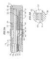
- the cylindrical distal portion 106 of the housing 102extends around the distal end of the distal barrel 120 of the piston receiving assembly 116 .
- the proximal end of the distal barrel 120along with the universal coupling and proximal barrel 122 of the piston receiving assembly 116 fit within the proximal portion 108 of the housing 102 .
- the piston 114is slidably disposed within the piston chamber 119 of the distal barrel 120 , as described above.
- the proximal end of the catheter body 12is fixedly attached to the distal tip 118 of the piston 114 by any suitable mechanism, preferably using a shrink sleeve as is known in the art.
- Rotation of the catheter body 12is affected by rotation of the thumb control 104 relative to the handle housing 102 .
- the piston 114is keyed to the thumb control 104 so that rotation of the thumb control results in corresponding rotation of the piston.
- the distal end of the piston 114comprises a distal ring 184 having spaces or breaks 186 on its top and bottom sides.
- the interior of the thumb control 104has two protrusions (not shown) that fit into the spaces 186 . When the thumb control 104 is assembled over the piston 114 , the protrusions mate with the spaces in the distal ring 184 so that rotation of the thumb control correspondingly causes rotation of the piston.
Landscapes
- Health & Medical Sciences (AREA)
- Engineering & Computer Science (AREA)
- Life Sciences & Earth Sciences (AREA)
- Heart & Thoracic Surgery (AREA)
- Biomedical Technology (AREA)
- Veterinary Medicine (AREA)
- Public Health (AREA)
- General Health & Medical Sciences (AREA)
- Animal Behavior & Ethology (AREA)
- Surgery (AREA)
- Nuclear Medicine, Radiotherapy & Molecular Imaging (AREA)
- Cardiology (AREA)
- Biophysics (AREA)
- Pulmonology (AREA)
- Plasma & Fusion (AREA)
- Physics & Mathematics (AREA)
- Medical Informatics (AREA)
- Mechanical Engineering (AREA)
- Otolaryngology (AREA)
- Molecular Biology (AREA)
- Anesthesiology (AREA)
- Hematology (AREA)
- Vascular Medicine (AREA)
- Radiology & Medical Imaging (AREA)
- Media Introduction/Drainage Providing Device (AREA)
- Electrotherapy Devices (AREA)
- Endoscopes (AREA)
- Materials For Medical Uses (AREA)
Abstract
Description
Claims (16)
Priority Applications (2)
| Application Number | Priority Date | Filing Date | Title |
|---|---|---|---|
| US10/868,277US7819857B2 (en) | 1999-03-03 | 2004-06-14 | Deflectable catheter |
| US12/900,441US8257344B2 (en) | 1999-03-03 | 2010-10-07 | Deflectable catheter |
Applications Claiming Priority (3)
| Application Number | Priority Date | Filing Date | Title |
|---|---|---|---|
| US09/261,931US6374476B1 (en) | 1999-03-03 | 1999-03-03 | Method for making a catheter tip section |
| US10/071,118US6783521B2 (en) | 1999-03-03 | 2002-02-08 | Deflectable catheter |
| US10/868,277US7819857B2 (en) | 1999-03-03 | 2004-06-14 | Deflectable catheter |
Related Parent Applications (1)
| Application Number | Title | Priority Date | Filing Date |
|---|---|---|---|
| US10/071,118ContinuationUS6783521B2 (en) | 1999-03-03 | 2002-02-08 | Deflectable catheter |
Related Child Applications (1)
| Application Number | Title | Priority Date | Filing Date |
|---|---|---|---|
| US12/900,441ContinuationUS8257344B2 (en) | 1999-03-03 | 2010-10-07 | Deflectable catheter |
Publications (2)
| Publication Number | Publication Date |
|---|---|
| US20040225256A1 US20040225256A1 (en) | 2004-11-11 |
| US7819857B2true US7819857B2 (en) | 2010-10-26 |
Family
ID=22995502
Family Applications (4)
| Application Number | Title | Priority Date | Filing Date |
|---|---|---|---|
| US09/261,931Expired - LifetimeUS6374476B1 (en) | 1999-03-03 | 1999-03-03 | Method for making a catheter tip section |
| US10/071,118Expired - LifetimeUS6783521B2 (en) | 1999-03-03 | 2002-02-08 | Deflectable catheter |
| US10/868,277Expired - Fee RelatedUS7819857B2 (en) | 1999-03-03 | 2004-06-14 | Deflectable catheter |
| US12/900,441Expired - Fee RelatedUS8257344B2 (en) | 1999-03-03 | 2010-10-07 | Deflectable catheter |
Family Applications Before (2)
| Application Number | Title | Priority Date | Filing Date |
|---|---|---|---|
| US09/261,931Expired - LifetimeUS6374476B1 (en) | 1999-03-03 | 1999-03-03 | Method for making a catheter tip section |
| US10/071,118Expired - LifetimeUS6783521B2 (en) | 1999-03-03 | 2002-02-08 | Deflectable catheter |
Family Applications After (1)
| Application Number | Title | Priority Date | Filing Date |
|---|---|---|---|
| US12/900,441Expired - Fee RelatedUS8257344B2 (en) | 1999-03-03 | 2010-10-07 | Deflectable catheter |
Country Status (5)
| Country | Link |
|---|---|
| US (4) | US6374476B1 (en) |
| EP (1) | EP1033144B1 (en) |
| JP (1) | JP4267163B2 (en) |
| AT (1) | ATE308359T1 (en) |
| DE (1) | DE60023577T2 (en) |
Cited By (6)
| Publication number | Priority date | Publication date | Assignee | Title |
|---|---|---|---|---|
| US20110021900A1 (en)* | 1999-03-03 | 2011-01-27 | Biosense Webster | Deflectable Catheter |
| US20130116705A1 (en)* | 2011-05-03 | 2013-05-09 | Amr Salahieh | Steerable Delivery Sheaths |
| US8808345B2 (en) | 2008-12-31 | 2014-08-19 | Medtronic Ardian Luxembourg S.A.R.L. | Handle assemblies for intravascular treatment devices and associated systems and methods |
| US10420537B2 (en) | 2015-03-27 | 2019-09-24 | Shifamed Holdings, Llc | Steerable medical devices, systems, and methods of use |
| US10933221B2 (en) | 2015-11-09 | 2021-03-02 | Kalila Medical, Inc. | Steering assemblies for medical devices, and methods of use |
| US11052226B2 (en) | 2015-04-24 | 2021-07-06 | Kalila Medical, Inc. | Steerable medical devices, systems, and methods of use |
Families Citing this family (95)
| Publication number | Priority date | Publication date | Assignee | Title |
|---|---|---|---|---|
| US20060009740A1 (en)* | 2001-08-28 | 2006-01-12 | Michael Higgins | Multiple lumen catheter having a soft tip |
| US6961602B2 (en)* | 2001-12-31 | 2005-11-01 | Biosense Webster, Inc. | Catheter having multiple spines each having electrical mapping and location sensing capabilities |
| US6925318B2 (en) | 2002-06-14 | 2005-08-02 | Scimed Life Systems, Inc. | Medical probe with variable tip length and shape |
| US7029467B2 (en)* | 2002-07-16 | 2006-04-18 | Edwards Lifesciences Corporation | Multiple lumen catheter having a soft tip |
| US6999809B2 (en)* | 2002-07-16 | 2006-02-14 | Edwards Lifesciences Corporation | Central venous catheter having a soft tip and fiber optics |
| US7089045B2 (en)* | 2002-08-30 | 2006-08-08 | Biosense Webster, Inc. | Catheter and method for mapping Purkinje fibers |
| US7087064B1 (en) | 2002-10-15 | 2006-08-08 | Advanced Cardiovascular Systems, Inc. | Apparatuses and methods for heart valve repair |
| US7027851B2 (en)* | 2002-10-30 | 2006-04-11 | Biosense Webster, Inc. | Multi-tip steerable catheter |
| US8187324B2 (en) | 2002-11-15 | 2012-05-29 | Advanced Cardiovascular Systems, Inc. | Telescoping apparatus for delivering and adjusting a medical device in a vessel |
| US20050256452A1 (en)* | 2002-11-15 | 2005-11-17 | Demarchi Thomas | Steerable vascular sheath |
| US7404824B1 (en)* | 2002-11-15 | 2008-07-29 | Advanced Cardiovascular Systems, Inc. | Valve aptation assist device |
| US7485143B2 (en)* | 2002-11-15 | 2009-02-03 | Abbott Cardiovascular Systems Inc. | Apparatuses and methods for heart valve repair |
| US7335213B1 (en) | 2002-11-15 | 2008-02-26 | Abbott Cardiovascular Systems Inc. | Apparatus and methods for heart valve repair |
| US6945978B1 (en) | 2002-11-15 | 2005-09-20 | Advanced Cardiovascular Systems, Inc. | Heart valve catheter |
| US9149602B2 (en) | 2005-04-22 | 2015-10-06 | Advanced Cardiovascular Systems, Inc. | Dual needle delivery system |
| US7981152B1 (en) | 2004-12-10 | 2011-07-19 | Advanced Cardiovascular Systems, Inc. | Vascular delivery system for accessing and delivering devices into coronary sinus and other vascular sites |
| US7331972B1 (en) | 2002-11-15 | 2008-02-19 | Abbott Cardiovascular Systems Inc. | Heart valve chord cutter |
| US7003342B2 (en)* | 2003-06-02 | 2006-02-21 | Biosense Webster, Inc. | Catheter and method for mapping a pulmonary vein |
| US7818048B2 (en) | 2003-06-02 | 2010-10-19 | Biosense Webster, Inc. | Catheter and method for mapping a pulmonary vein |
| US7717865B2 (en)* | 2003-09-30 | 2010-05-18 | Boston Scientific Scimed, Inc. | Side loading wire torquing device |
| US7998112B2 (en)* | 2003-09-30 | 2011-08-16 | Abbott Cardiovascular Systems Inc. | Deflectable catheter assembly and method of making same |
| US7972350B2 (en)* | 2004-01-29 | 2011-07-05 | Boston Scientific Scimed, Inc. | Catheter tip |
| US9782130B2 (en) | 2004-05-28 | 2017-10-10 | St. Jude Medical, Atrial Fibrillation Division, Inc. | Robotic surgical system |
| US8528565B2 (en) | 2004-05-28 | 2013-09-10 | St. Jude Medical, Atrial Fibrillation Division, Inc. | Robotic surgical system and method for automated therapy delivery |
| US7632265B2 (en) | 2004-05-28 | 2009-12-15 | St. Jude Medical, Atrial Fibrillation Division, Inc. | Radio frequency ablation servo catheter and method |
| US10258285B2 (en) | 2004-05-28 | 2019-04-16 | St. Jude Medical, Atrial Fibrillation Division, Inc. | Robotic surgical system and method for automated creation of ablation lesions |
| US10863945B2 (en) | 2004-05-28 | 2020-12-15 | St. Jude Medical, Atrial Fibrillation Division, Inc. | Robotic surgical system with contact sensing feature |
| US7974674B2 (en) | 2004-05-28 | 2011-07-05 | St. Jude Medical, Atrial Fibrillation Division, Inc. | Robotic surgical system and method for surface modeling |
| US8755864B2 (en) | 2004-05-28 | 2014-06-17 | St. Jude Medical, Atrial Fibrillation Division, Inc. | Robotic surgical system and method for diagnostic data mapping |
| CA2600277A1 (en)* | 2005-03-04 | 2006-09-08 | Cathrx Ltd | A catheter handle and a catheter assembly including such a handle |
| US8155910B2 (en) | 2005-05-27 | 2012-04-10 | St. Jude Medical, Atrial Fibrillation Divison, Inc. | Robotically controlled catheter and method of its calibration |
| US7553305B2 (en)* | 2005-06-09 | 2009-06-30 | Enpath Medical, Inc. | Push-pull wire anchor |
| CA2623922C (en)* | 2005-09-27 | 2015-03-24 | Allegiance Corporation | Medical suction and irrigation device handpiece |
| US7546165B2 (en)* | 2005-12-19 | 2009-06-09 | Cardiac Pacemakers, Inc. | Interconnections of implantable lead conductors and electrodes and reinforcement therefor |
| US8540696B2 (en)* | 2005-12-29 | 2013-09-24 | Biosense Webster, Inc. | Deflectable catheter with a high modulus fiber puller element |
| US9833595B2 (en)* | 2005-12-30 | 2017-12-05 | Biosense Webster, Inc. | Dual-lever bi-directional handle |
| US20080234660A2 (en)* | 2006-05-16 | 2008-09-25 | Sarah Cumming | Steerable Catheter Using Flat Pull Wires and Method of Making Same |
| US20080091169A1 (en)* | 2006-05-16 | 2008-04-17 | Wayne Heideman | Steerable catheter using flat pull wires and having torque transfer layer made of braided flat wires |
| US20080046059A1 (en)* | 2006-08-04 | 2008-02-21 | Zarembo Paul E | Lead including a heat fused or formed lead body |
| USD550356S1 (en)* | 2006-08-04 | 2007-09-04 | Cathrx Ltd | Catheter handle |
| US7917229B2 (en) | 2006-08-31 | 2011-03-29 | Cardiac Pacemakers, Inc. | Lead assembly including a polymer interconnect and methods related thereto |
| US20080077050A1 (en)* | 2006-09-08 | 2008-03-27 | Radi Medical Systems Ab | Electrical connector for medical device |
| JP4706008B2 (en)* | 2006-10-26 | 2011-06-22 | 有限会社リバー精工 | Cardiac catheter |
| US20080275426A1 (en)* | 2007-05-03 | 2008-11-06 | Boston Scientific Scimed, Inc. | Flexible and Durable Tip |
| AU2008202483B2 (en)* | 2007-06-15 | 2011-07-14 | Cathrx Ltd | A deflectable stylet |
| US7979108B2 (en)* | 2007-08-27 | 2011-07-12 | William Harrison Zurn | Automated vessel repair system, devices and methods |
| DE102007043127A1 (en) | 2007-09-10 | 2009-03-12 | Biotronik Crm Patent Ag | Electrode device for physiological use, in particular in cardiology |
| US8647323B2 (en)* | 2007-12-30 | 2014-02-11 | St. Jude Medical, Atrial Fibrillation Division, Inc. | Catheter shaft with multiple reinforcing layers and method of its manufacture |
| US8431057B2 (en) | 2007-12-30 | 2013-04-30 | St. Jude Medical, Atrial Fibrillation Division, Inc. | Catheter shaft and method of its manufacture |
| US8684999B2 (en)* | 2007-12-31 | 2014-04-01 | St. Jude Medical, Atrial Fibrillation Division, Inc. | Catheter shaft and method of manufacture |
| JP4224124B1 (en)* | 2008-05-21 | 2009-02-12 | 日本ライフライン株式会社 | Catheter handle |
| US8452416B2 (en)* | 2008-06-27 | 2013-05-28 | St. Jude Medical Ab | Medical lead assembly and method for implantation thereof |
| US8006594B2 (en)* | 2008-08-11 | 2011-08-30 | Cardiac Dimensions, Inc. | Catheter cutting tool |
| US8219209B2 (en) | 2008-08-15 | 2012-07-10 | Cardiac Pacemakers, Inc. | Implantable medical lead having reduced dimension tubing transition |
| US10046141B2 (en)* | 2008-12-30 | 2018-08-14 | Biosense Webster, Inc. | Deflectable sheath introducer |
| US8676290B2 (en) | 2010-05-11 | 2014-03-18 | St. Jude Medical, Atrial Fibrillation Division, Inc. | Multi-directional catheter control handle |
| US8123721B2 (en)* | 2008-12-31 | 2012-02-28 | St. Jude Medical, Atrial Fibrillation Division, Inc. | Catheter having independently-deflectable segments and method of its manufacture |
| US8556850B2 (en) | 2008-12-31 | 2013-10-15 | St. Jude Medical, Atrial Fibrillation Division, Inc. | Shaft and handle for a catheter with independently-deflectable segments |
| US8372033B2 (en) | 2008-12-31 | 2013-02-12 | St. Jude Medical, Atrial Fibrillation Division, Inc. | Catheter having proximal heat sensitive deflection mechanism and related methods of use and manufacturing |
| US9833616B2 (en)* | 2009-01-02 | 2017-12-05 | Medtronic, Inc. | System and method for cardiac lead |
| US8478424B2 (en)* | 2009-02-23 | 2013-07-02 | Medtronic, Inc. | Medical lead having coaxial connector |
| US8061026B2 (en)* | 2009-02-23 | 2011-11-22 | Medtronic, Inc. | Method for making smooth transitions between differing lead segments |
| JP2010227137A (en)* | 2009-03-25 | 2010-10-14 | Sumitomo Bakelite Co Ltd | Catheter |
| FR2948596B1 (en)* | 2009-07-31 | 2012-07-20 | Dexterite Surgical | MANIPULATOR HAND HELD AND SYMMETRIC PRETENSION |
| US8906013B2 (en) | 2010-04-09 | 2014-12-09 | Endosense Sa | Control handle for a contact force ablation catheter |
| USD653335S1 (en) | 2010-04-29 | 2012-01-31 | Greatbatch Ltd. | Catheter handle |
| US9289147B2 (en) | 2010-05-11 | 2016-03-22 | St. Jude Medical, Atrial Fibrillation Division, Inc. | Multi-directional flexible wire harness for medical devices |
| USD638934S1 (en) | 2010-10-22 | 2011-05-31 | Greatbatch Ltd. | Catheter handle |
| WO2012088564A1 (en)* | 2010-12-27 | 2012-07-05 | Cathrx Ltd | A modular catheter |
| USD726905S1 (en) | 2011-05-11 | 2015-04-14 | St. Jude Medical, Atrial Fibrillation Division, Inc. | Control handle for a medical device |
| US8663209B2 (en) | 2012-01-24 | 2014-03-04 | William Harrison Zurn | Vessel clearing apparatus, devices and methods |
| US9314299B2 (en) | 2012-03-21 | 2016-04-19 | Biosense Webster (Israel) Ltd. | Flower catheter for mapping and ablating veinous and other tubular locations |
| US9833207B2 (en) | 2012-08-08 | 2017-12-05 | William Harrison Zurn | Analysis and clearing module, system and method |
| US10383680B2 (en)* | 2012-08-31 | 2019-08-20 | Nico Corporation | Bi-polar surgical instrument |
| US9549666B2 (en) | 2012-11-10 | 2017-01-24 | Curvo Medical, Inc. | Coaxial micro-endoscope |
| US9233225B2 (en) | 2012-11-10 | 2016-01-12 | Curvo Medical, Inc. | Coaxial bi-directional catheter |
| US9174023B2 (en)* | 2013-01-07 | 2015-11-03 | Biosense Webster (Israel) Ltd. | Unidirectional catheter control handle with tensioning control |
| US9308349B2 (en) | 2013-02-08 | 2016-04-12 | Vention Medical Advanced Components, Inc. | Universal catheter handle |
| US9962533B2 (en) | 2013-02-14 | 2018-05-08 | William Harrison Zurn | Module for treatment of medical conditions; system for making module and methods of making module |
| US10071222B2 (en)* | 2013-03-16 | 2018-09-11 | Clph, Llc | Electrode catheters and methods for making them |
| US9855404B2 (en) | 2013-05-03 | 2018-01-02 | St. Jude Medical International Holding S.À R.L. | Dual bend radii steering catheter |
| US9839765B2 (en)* | 2013-11-12 | 2017-12-12 | St. Jude Medical, Cardiology Division, Inc. | Transfemoral mitral valve repair delivery device |
| USD806244S1 (en) | 2014-01-31 | 2017-12-26 | Nordson Corporation | Catheter actuation handle |
| WO2015143372A2 (en)* | 2014-03-20 | 2015-09-24 | Medtronic Ardian Luxembourg S.A.R.L. | Neuromodulation catheters and related devices, systems, and methods |
| WO2016071378A1 (en)* | 2014-11-04 | 2016-05-12 | Koninklijke Philips N.V. | Steerable medical device, and use of a pull wire ring therein |
| CA2994262C (en) | 2015-07-30 | 2023-09-19 | Gmedix, Inc. | Coronary guide catheter |
| US10357634B2 (en) | 2016-07-28 | 2019-07-23 | Cook Medical Technologies Llc | Steerable catheter with wire-tensioning mechanism |
| US11517715B2 (en) | 2018-01-02 | 2022-12-06 | Biosense Webster (Israel) Ltd. | Deflectable medical probe |
| US11517716B2 (en)* | 2018-12-29 | 2022-12-06 | Biosense Webster (Israel) Ltd. | Puller wire t-bar for medical catheter |
| CA3126817C (en)* | 2019-01-18 | 2022-11-01 | Ipg Photonics Corporation | Ergonomic steering handle for a flexible catheter |
| JP7210699B2 (en)* | 2019-03-25 | 2023-01-23 | 日本ライフライン株式会社 | catheter |
| US11471650B2 (en) | 2019-09-20 | 2022-10-18 | Biosense Webster (Israel) Ltd. | Mechanism for manipulating a puller wire |
| EP4240460A4 (en) | 2020-11-09 | 2024-05-08 | Agile Devices, Inc. | CATHETER CONTROL DEVICES |
| JP7727489B2 (en)* | 2021-11-02 | 2025-08-21 | 株式会社カネカ | Method for manufacturing an electrode catheter |
| US20230218861A1 (en) | 2022-01-12 | 2023-07-13 | Canon U.S.A., Inc. | Ergonomic catheter handle |
Citations (23)
| Publication number | Priority date | Publication date | Assignee | Title |
|---|---|---|---|---|
| US3605725A (en)* | 1968-08-07 | 1971-09-20 | Medi Tech Inc | Controlled motion devices |
| US4690175A (en)* | 1981-11-17 | 1987-09-01 | Kabushiki Kaisha Medos Kenkyusho | Flexible tube for endoscope |
| US4817613A (en) | 1987-07-13 | 1989-04-04 | Devices For Vascular Intervention, Inc. | Guiding catheter |
| US4960134A (en) | 1988-11-18 | 1990-10-02 | Webster Wilton W Jr | Steerable catheter |
| US5057092A (en) | 1990-04-04 | 1991-10-15 | Webster Wilton W Jr | Braided catheter with low modulus warp |
| US5336182A (en) | 1990-02-02 | 1994-08-09 | Ep Technologies, Inc. | Catheter steering mechanism |
| US5364351A (en) | 1992-11-13 | 1994-11-15 | Ep Technologies, Inc. | Catheter steering mechanism |
| US5368564A (en) | 1992-12-23 | 1994-11-29 | Angeion Corporation | Steerable catheter |
| WO1995002995A1 (en) | 1993-07-20 | 1995-02-02 | Biosense, Inc. | Apparatus and method for treating cardiac arrhythmias |
| US5431168A (en) | 1993-08-23 | 1995-07-11 | Cordis-Webster, Inc. | Steerable open-lumen catheter |
| US5445624A (en)* | 1994-01-21 | 1995-08-29 | Exonix Research Corporation | Catheter with progressively compliant tip |
| US5478330A (en) | 1992-12-01 | 1995-12-26 | Cardiac Pathways Corporation | Steerable catheter with adjustable bend location and/or radius and method |
| US5533987A (en) | 1992-04-09 | 1996-07-09 | Scimed Lifesystems, Inc. | Dilatation catheter with polymide encased stainless steel braid proximal shaft |
| US5542924A (en) | 1992-11-02 | 1996-08-06 | Catheter Imaging Systems | Method of forming a catheter having a multiple durometer |
| US5558091A (en) | 1993-10-06 | 1996-09-24 | Biosense, Inc. | Magnetic determination of position and orientation |
| WO1996040344A1 (en) | 1995-06-07 | 1996-12-19 | C.R. Bard, Inc. | Bidirectional steering catheter |
| US5622665A (en) | 1994-04-20 | 1997-04-22 | Wang; James C. | Method for making tubing |
| US5792124A (en)* | 1995-01-04 | 1998-08-11 | Medtronic, Inc. | Reinforced catheter which gets softer towards the distal tip |
| US5827278A (en) | 1997-05-20 | 1998-10-27 | Cordis Webster, Inc. | Deflectable tip electrode catheter with nylon stiffener and compression coil |
| US5826576A (en)* | 1996-08-08 | 1998-10-27 | Medtronic, Inc. | Electrophysiology catheter with multifunction wire and method for making |
| US5848986A (en) | 1992-08-12 | 1998-12-15 | Vidamed, Inc. | Medical probe with electrode guide for transurethral ablation |
| US6123699A (en) | 1997-09-05 | 2000-09-26 | Cordis Webster, Inc. | Omni-directional steerable catheter |
| US6203507B1 (en)* | 1999-03-03 | 2001-03-20 | Cordis Webster, Inc. | Deflectable catheter with ergonomic handle |
Family Cites Families (8)
| Publication number | Priority date | Publication date | Assignee | Title |
|---|---|---|---|---|
| JP2875315B2 (en) | 1989-12-27 | 1999-03-31 | テルモ株式会社 | Angiographic catheter |
| US5327905A (en)* | 1992-02-14 | 1994-07-12 | Boaz Avitall | Biplanar deflectable catheter for arrhythmogenic tissue ablation |
| JP3526598B2 (en) | 1992-12-04 | 2004-05-17 | シー・アール・バード・インコーポレーテッド | Catheter and independent handle / actuator for independent proximal and distal control |
| JPH07124243A (en) | 1993-11-05 | 1995-05-16 | Mitsubishi Cable Ind Ltd | Torque tube having gradient rigidity and catheter using the same |
| US5465716A (en)* | 1993-11-22 | 1995-11-14 | Avitall; Boaz | Catheter control handle |
| US5911715A (en) | 1994-02-14 | 1999-06-15 | Scimed Life Systems, Inc. | Guide catheter having selected flexural modulus segments |
| US6554794B1 (en)* | 1997-09-24 | 2003-04-29 | Richard L. Mueller | Non-deforming deflectable multi-lumen catheter |
| US6374476B1 (en)* | 1999-03-03 | 2002-04-23 | Codris Webster, Inc. | Method for making a catheter tip section |
- 1999
- 1999-03-03USUS09/261,931patent/US6374476B1/ennot_activeExpired - Lifetime
- 2000
- 2000-03-02EPEP00301692Apatent/EP1033144B1/ennot_activeExpired - Lifetime
- 2000-03-02DEDE60023577Tpatent/DE60023577T2/ennot_activeExpired - Lifetime
- 2000-03-02ATAT00301692Tpatent/ATE308359T1/ennot_activeIP Right Cessation
- 2000-03-02JPJP2000057504Apatent/JP4267163B2/ennot_activeExpired - Lifetime
- 2002
- 2002-02-08USUS10/071,118patent/US6783521B2/ennot_activeExpired - Lifetime
- 2004
- 2004-06-14USUS10/868,277patent/US7819857B2/ennot_activeExpired - Fee Related
- 2010
- 2010-10-07USUS12/900,441patent/US8257344B2/ennot_activeExpired - Fee Related
Patent Citations (29)
| Publication number | Priority date | Publication date | Assignee | Title |
|---|---|---|---|---|
| US3605725A (en)* | 1968-08-07 | 1971-09-20 | Medi Tech Inc | Controlled motion devices |
| US4690175A (en)* | 1981-11-17 | 1987-09-01 | Kabushiki Kaisha Medos Kenkyusho | Flexible tube for endoscope |
| US4817613A (en) | 1987-07-13 | 1989-04-04 | Devices For Vascular Intervention, Inc. | Guiding catheter |
| US4960134A (en) | 1988-11-18 | 1990-10-02 | Webster Wilton W Jr | Steerable catheter |
| USRE34502E (en)* | 1988-11-18 | 1994-01-11 | Webster, Jr.; Wilton W. | Steerable catheter |
| US5336182A (en) | 1990-02-02 | 1994-08-09 | Ep Technologies, Inc. | Catheter steering mechanism |
| US5057092A (en) | 1990-04-04 | 1991-10-15 | Webster Wilton W Jr | Braided catheter with low modulus warp |
| US5533987A (en) | 1992-04-09 | 1996-07-09 | Scimed Lifesystems, Inc. | Dilatation catheter with polymide encased stainless steel braid proximal shaft |
| US5848986A (en) | 1992-08-12 | 1998-12-15 | Vidamed, Inc. | Medical probe with electrode guide for transurethral ablation |
| US5542924A (en) | 1992-11-02 | 1996-08-06 | Catheter Imaging Systems | Method of forming a catheter having a multiple durometer |
| US5364351A (en) | 1992-11-13 | 1994-11-15 | Ep Technologies, Inc. | Catheter steering mechanism |
| US5478330A (en) | 1992-12-01 | 1995-12-26 | Cardiac Pathways Corporation | Steerable catheter with adjustable bend location and/or radius and method |
| US5368564A (en) | 1992-12-23 | 1994-11-29 | Angeion Corporation | Steerable catheter |
| US5480422A (en) | 1993-07-20 | 1996-01-02 | Biosense, Inc. | Apparatus for treating cardiac arrhythmias |
| US5391199A (en) | 1993-07-20 | 1995-02-21 | Biosense, Inc. | Apparatus and method for treating cardiac arrhythmias |
| WO1995002995A1 (en) | 1993-07-20 | 1995-02-02 | Biosense, Inc. | Apparatus and method for treating cardiac arrhythmias |
| US5546951A (en) | 1993-07-20 | 1996-08-20 | Biosense, Inc. | Method and apparatus for studying cardiac arrhythmias |
| US5443489A (en) | 1993-07-20 | 1995-08-22 | Biosense, Inc. | Apparatus and method for ablation |
| US5431168A (en) | 1993-08-23 | 1995-07-11 | Cordis-Webster, Inc. | Steerable open-lumen catheter |
| US5558091A (en) | 1993-10-06 | 1996-09-24 | Biosense, Inc. | Magnetic determination of position and orientation |
| US5445624A (en)* | 1994-01-21 | 1995-08-29 | Exonix Research Corporation | Catheter with progressively compliant tip |
| US5622665A (en) | 1994-04-20 | 1997-04-22 | Wang; James C. | Method for making tubing |
| US5792124A (en)* | 1995-01-04 | 1998-08-11 | Medtronic, Inc. | Reinforced catheter which gets softer towards the distal tip |
| WO1996040344A1 (en) | 1995-06-07 | 1996-12-19 | C.R. Bard, Inc. | Bidirectional steering catheter |
| US5826576A (en)* | 1996-08-08 | 1998-10-27 | Medtronic, Inc. | Electrophysiology catheter with multifunction wire and method for making |
| US5987344A (en)* | 1996-08-08 | 1999-11-16 | Medtronic, Inc. | Handle for catheter assembly with multifunction wire |
| US5827278A (en) | 1997-05-20 | 1998-10-27 | Cordis Webster, Inc. | Deflectable tip electrode catheter with nylon stiffener and compression coil |
| US6123699A (en) | 1997-09-05 | 2000-09-26 | Cordis Webster, Inc. | Omni-directional steerable catheter |
| US6203507B1 (en)* | 1999-03-03 | 2001-03-20 | Cordis Webster, Inc. | Deflectable catheter with ergonomic handle |
Cited By (9)
| Publication number | Priority date | Publication date | Assignee | Title |
|---|---|---|---|---|
| US20110021900A1 (en)* | 1999-03-03 | 2011-01-27 | Biosense Webster | Deflectable Catheter |
| US8257344B2 (en)* | 1999-03-03 | 2012-09-04 | Biosense Webster, Inc. | Deflectable catheter |
| US8808345B2 (en) | 2008-12-31 | 2014-08-19 | Medtronic Ardian Luxembourg S.A.R.L. | Handle assemblies for intravascular treatment devices and associated systems and methods |
| US9586025B2 (en) | 2009-06-24 | 2017-03-07 | Shifamed Holdings, Llc | Steerable delivery sheaths |
| US10188832B2 (en) | 2009-06-24 | 2019-01-29 | Shifamed Holdings, Llc | Steerable delivery sheaths |
| US20130116705A1 (en)* | 2011-05-03 | 2013-05-09 | Amr Salahieh | Steerable Delivery Sheaths |
| US10420537B2 (en) | 2015-03-27 | 2019-09-24 | Shifamed Holdings, Llc | Steerable medical devices, systems, and methods of use |
| US11052226B2 (en) | 2015-04-24 | 2021-07-06 | Kalila Medical, Inc. | Steerable medical devices, systems, and methods of use |
| US10933221B2 (en) | 2015-11-09 | 2021-03-02 | Kalila Medical, Inc. | Steering assemblies for medical devices, and methods of use |
Also Published As
| Publication number | Publication date |
|---|---|
| US20020077590A1 (en) | 2002-06-20 |
| DE60023577T2 (en) | 2006-07-27 |
| US6374476B1 (en) | 2002-04-23 |
| JP4267163B2 (en) | 2009-05-27 |
| EP1033144B1 (en) | 2005-11-02 |
| US6783521B2 (en) | 2004-08-31 |
| EP1033144A1 (en) | 2000-09-06 |
| US8257344B2 (en) | 2012-09-04 |
| JP2000288095A (en) | 2000-10-17 |
| DE60023577D1 (en) | 2005-12-08 |
| ATE308359T1 (en) | 2005-11-15 |
| US20040225256A1 (en) | 2004-11-11 |
| US20110021900A1 (en) | 2011-01-27 |
Similar Documents
| Publication | Publication Date | Title |
|---|---|---|
| US7819857B2 (en) | Deflectable catheter | |
| US6203507B1 (en) | Deflectable catheter with ergonomic handle | |
| US6210407B1 (en) | Bi-directional electrode catheter | |
| US6522933B2 (en) | Steerable catheter with a control handle having a pulley mechanism | |
| US6468260B1 (en) | Single gear drive bidirectional control handle for steerable catheter | |
| EP0928600B1 (en) | Steerable catheter with electromagnetic sensor | |
| EP1723981B1 (en) | Steerable catheter with distal tip orientation sheaths | |
| US6171277B1 (en) | Bi-directional control handle for steerable catheter | |
| US6602242B1 (en) | Irrigated tip catheter | |
| US6183435B1 (en) | Multi-directional steerable catheters and control handles | |
| US6198974B1 (en) | Bi-directional steerable catheter | |
| US6267746B1 (en) | Multi-directional steerable catheters and control handles | |
| US6551271B2 (en) | Asymmetrical bidirectional steerable catheter | |
| US6837867B2 (en) | Steerable catheter with reinforced tip | |
| JP4194691B2 (en) | Operable omnidirectional catheter | |
| US6569114B2 (en) | Steerable catheter with struts |
Legal Events
| Date | Code | Title | Description |
|---|---|---|---|
| AS | Assignment | Owner name:CORDIS WEBSTER, INC.,CALIFORNIA Free format text:ASSIGNMENT OF ASSIGNORS INTEREST;ASSIGNORS:PONZI, DEAN M.;BESHORE, CRAIG S.;REEL/FRAME:023975/0882 Effective date:19990405 Owner name:BIOSENSE WEBSTER, INC.,CALIFORNIA Free format text:CHANGE OF NAME;ASSIGNOR:CORDIS WEBSTER, INC.;REEL/FRAME:023975/0906 Effective date:19990610 Owner name:CORDIS WEBSTER, INC., CALIFORNIA Free format text:ASSIGNMENT OF ASSIGNORS INTEREST;ASSIGNORS:PONZI, DEAN M.;BESHORE, CRAIG S.;REEL/FRAME:023975/0882 Effective date:19990405 Owner name:BIOSENSE WEBSTER, INC., CALIFORNIA Free format text:CHANGE OF NAME;ASSIGNOR:CORDIS WEBSTER, INC.;REEL/FRAME:023975/0906 Effective date:19990610 | |
| STCF | Information on status: patent grant | Free format text:PATENTED CASE | |
| FPAY | Fee payment | Year of fee payment:4 | |
| MAFP | Maintenance fee payment | Free format text:PAYMENT OF MAINTENANCE FEE, 8TH YEAR, LARGE ENTITY (ORIGINAL EVENT CODE: M1552) Year of fee payment:8 | |
| FEPP | Fee payment procedure | Free format text:MAINTENANCE FEE REMINDER MAILED (ORIGINAL EVENT CODE: REM.); ENTITY STATUS OF PATENT OWNER: LARGE ENTITY | |
| LAPS | Lapse for failure to pay maintenance fees | Free format text:PATENT EXPIRED FOR FAILURE TO PAY MAINTENANCE FEES (ORIGINAL EVENT CODE: EXP.); ENTITY STATUS OF PATENT OWNER: LARGE ENTITY | |
| STCH | Information on status: patent discontinuation | Free format text:PATENT EXPIRED DUE TO NONPAYMENT OF MAINTENANCE FEES UNDER 37 CFR 1.362 | |
| FP | Lapsed due to failure to pay maintenance fee | Effective date:20221026 |