US7818854B2 - Ultrasound radiating members for catheter - Google Patents
Ultrasound radiating members for catheterDownload PDFInfo
- Publication number
- US7818854B2 US7818854B2US12/371,544US37154409AUS7818854B2US 7818854 B2US7818854 B2US 7818854B2US 37154409 AUS37154409 AUS 37154409AUS 7818854 B2US7818854 B2US 7818854B2
- Authority
- US
- United States
- Prior art keywords
- ultrasound radiating
- catheter
- ultrasonic
- radiating members
- delivery
- Prior art date
- Legal status (The legal status is an assumption and is not a legal conclusion. Google has not performed a legal analysis and makes no representation as to the accuracy of the status listed.)
- Expired - Fee Related
Links
Images


Classifications
- A—HUMAN NECESSITIES
- A61—MEDICAL OR VETERINARY SCIENCE; HYGIENE
- A61B—DIAGNOSIS; SURGERY; IDENTIFICATION
- A61B17/00—Surgical instruments, devices or methods
- A61B17/22—Implements for squeezing-off ulcers or the like on inner organs of the body; Implements for scraping-out cavities of body organs, e.g. bones; for invasive removal or destruction of calculus using mechanical vibrations; for removing obstructions in blood vessels, not otherwise provided for
- A61B17/22004—Implements for squeezing-off ulcers or the like on inner organs of the body; Implements for scraping-out cavities of body organs, e.g. bones; for invasive removal or destruction of calculus using mechanical vibrations; for removing obstructions in blood vessels, not otherwise provided for using mechanical vibrations, e.g. ultrasonic shock waves
- A61B17/22012—Implements for squeezing-off ulcers or the like on inner organs of the body; Implements for scraping-out cavities of body organs, e.g. bones; for invasive removal or destruction of calculus using mechanical vibrations; for removing obstructions in blood vessels, not otherwise provided for using mechanical vibrations, e.g. ultrasonic shock waves in direct contact with, or very close to, the obstruction or concrement
- A61B17/2202—Implements for squeezing-off ulcers or the like on inner organs of the body; Implements for scraping-out cavities of body organs, e.g. bones; for invasive removal or destruction of calculus using mechanical vibrations; for removing obstructions in blood vessels, not otherwise provided for using mechanical vibrations, e.g. ultrasonic shock waves in direct contact with, or very close to, the obstruction or concrement the ultrasound transducer being inside patient's body at the distal end of the catheter
- A—HUMAN NECESSITIES
- A61—MEDICAL OR VETERINARY SCIENCE; HYGIENE
- A61M—DEVICES FOR INTRODUCING MEDIA INTO, OR ONTO, THE BODY; DEVICES FOR TRANSDUCING BODY MEDIA OR FOR TAKING MEDIA FROM THE BODY; DEVICES FOR PRODUCING OR ENDING SLEEP OR STUPOR
- A61M37/00—Other apparatus for introducing media into the body; Percutany, i.e. introducing medicines into the body by diffusion through the skin
- A61M37/0092—Other apparatus for introducing media into the body; Percutany, i.e. introducing medicines into the body by diffusion through the skin using ultrasonic, sonic or infrasonic vibrations, e.g. phonophoresis
- A—HUMAN NECESSITIES
- A61—MEDICAL OR VETERINARY SCIENCE; HYGIENE
- A61B—DIAGNOSIS; SURGERY; IDENTIFICATION
- A61B17/00—Surgical instruments, devices or methods
- A61B17/22—Implements for squeezing-off ulcers or the like on inner organs of the body; Implements for scraping-out cavities of body organs, e.g. bones; for invasive removal or destruction of calculus using mechanical vibrations; for removing obstructions in blood vessels, not otherwise provided for
- A61B2017/22001—Angioplasty, e.g. PCTA
- A61B2017/22002—Angioplasty, e.g. PCTA preventing restenosis
- A—HUMAN NECESSITIES
- A61—MEDICAL OR VETERINARY SCIENCE; HYGIENE
- A61B—DIAGNOSIS; SURGERY; IDENTIFICATION
- A61B17/00—Surgical instruments, devices or methods
- A61B17/22—Implements for squeezing-off ulcers or the like on inner organs of the body; Implements for scraping-out cavities of body organs, e.g. bones; for invasive removal or destruction of calculus using mechanical vibrations; for removing obstructions in blood vessels, not otherwise provided for
- A61B2017/22082—Implements for squeezing-off ulcers or the like on inner organs of the body; Implements for scraping-out cavities of body organs, e.g. bones; for invasive removal or destruction of calculus using mechanical vibrations; for removing obstructions in blood vessels, not otherwise provided for after introduction of a substance
- A—HUMAN NECESSITIES
- A61—MEDICAL OR VETERINARY SCIENCE; HYGIENE
- A61M—DEVICES FOR INTRODUCING MEDIA INTO, OR ONTO, THE BODY; DEVICES FOR TRANSDUCING BODY MEDIA OR FOR TAKING MEDIA FROM THE BODY; DEVICES FOR PRODUCING OR ENDING SLEEP OR STUPOR
- A61M25/00—Catheters; Hollow probes
- A61M25/0043—Catheters; Hollow probes characterised by structural features
- A61M2025/0057—Catheters delivering medicament other than through a conventional lumen, e.g. porous walls or hydrogel coatings
- A—HUMAN NECESSITIES
- A61—MEDICAL OR VETERINARY SCIENCE; HYGIENE
- A61M—DEVICES FOR INTRODUCING MEDIA INTO, OR ONTO, THE BODY; DEVICES FOR TRANSDUCING BODY MEDIA OR FOR TAKING MEDIA FROM THE BODY; DEVICES FOR PRODUCING OR ENDING SLEEP OR STUPOR
- A61M25/00—Catheters; Hollow probes
- A61M25/0043—Catheters; Hollow probes characterised by structural features
- Y—GENERAL TAGGING OF NEW TECHNOLOGICAL DEVELOPMENTS; GENERAL TAGGING OF CROSS-SECTIONAL TECHNOLOGIES SPANNING OVER SEVERAL SECTIONS OF THE IPC; TECHNICAL SUBJECTS COVERED BY FORMER USPC CROSS-REFERENCE ART COLLECTIONS [XRACs] AND DIGESTS
- Y10—TECHNICAL SUBJECTS COVERED BY FORMER USPC
- Y10T—TECHNICAL SUBJECTS COVERED BY FORMER US CLASSIFICATION
- Y10T29/00—Metal working
- Y10T29/42—Piezoelectric device making
- Y—GENERAL TAGGING OF NEW TECHNOLOGICAL DEVELOPMENTS; GENERAL TAGGING OF CROSS-SECTIONAL TECHNOLOGIES SPANNING OVER SEVERAL SECTIONS OF THE IPC; TECHNICAL SUBJECTS COVERED BY FORMER USPC CROSS-REFERENCE ART COLLECTIONS [XRACs] AND DIGESTS
- Y10—TECHNICAL SUBJECTS COVERED BY FORMER USPC
- Y10T—TECHNICAL SUBJECTS COVERED BY FORMER US CLASSIFICATION
- Y10T29/00—Metal working
- Y10T29/49—Method of mechanical manufacture
- Y10T29/49002—Electrical device making
- Y10T29/49005—Acoustic transducer
- Y—GENERAL TAGGING OF NEW TECHNOLOGICAL DEVELOPMENTS; GENERAL TAGGING OF CROSS-SECTIONAL TECHNOLOGIES SPANNING OVER SEVERAL SECTIONS OF THE IPC; TECHNICAL SUBJECTS COVERED BY FORMER USPC CROSS-REFERENCE ART COLLECTIONS [XRACs] AND DIGESTS
- Y10—TECHNICAL SUBJECTS COVERED BY FORMER USPC
- Y10T—TECHNICAL SUBJECTS COVERED BY FORMER US CLASSIFICATION
- Y10T29/00—Metal working
- Y10T29/49—Method of mechanical manufacture
- Y10T29/49002—Electrical device making
- Y10T29/49117—Conductor or circuit manufacturing
- Y10T29/49124—On flat or curved insulated base, e.g., printed circuit, etc.
- Y10T29/49155—Manufacturing circuit on or in base
- Y10T29/49156—Manufacturing circuit on or in base with selective destruction of conductive paths
- Y—GENERAL TAGGING OF NEW TECHNOLOGICAL DEVELOPMENTS; GENERAL TAGGING OF CROSS-SECTIONAL TECHNOLOGIES SPANNING OVER SEVERAL SECTIONS OF THE IPC; TECHNICAL SUBJECTS COVERED BY FORMER USPC CROSS-REFERENCE ART COLLECTIONS [XRACs] AND DIGESTS
- Y10—TECHNICAL SUBJECTS COVERED BY FORMER USPC
- Y10T—TECHNICAL SUBJECTS COVERED BY FORMER US CLASSIFICATION
- Y10T29/00—Metal working
- Y10T29/49—Method of mechanical manufacture
- Y10T29/49789—Obtaining plural product pieces from unitary workpiece
- Y10T29/49798—Dividing sequentially from leading end, e.g., by cutting or breaking
Definitions
- the present inventionrelates generally to ultrasound radiating members, and relates more specifically to ultrasound radiating members configured for use in medical applications to enhance the delivery and/or effect of a therapeutic compound.
- ultrasonic energycan be used to enhance the delivery and/or effect of various therapeutic compounds. See, for example, U.S. Pat. Nos. 4,821,740, 4,953,565 and 5,007,438.
- a catheterdelivers ultrasonic energy and a therapeutic compound to a specific treatment site within the body.
- Such a cathetertypically includes an ultrasonic assembly for generating the ultrasonic energy and a delivery lumen for delivering the therapeutic compound to the treatment site.
- the ultrasonic energycan be applied at the treatment site to enhance the therapeutic effect and/or the delivery of the therapeutic compound.
- Ultrasonic cathetershave successfully been used to treat human blood vessels that have become occluded or completely blocked by plaque, thrombi, emboli or other substances that reduce the blood carrying capacity of the vessel. See, for example, U.S. Pat. No. 6,001,069.
- solutions containing dissolution compoundscan be delivered directly to the blockage site using an ultrasonic catheter.
- ultrasonic energy generated by the catheterenhances the delivery and/or therapeutic effect of the dissolution compounds.
- Ultrasonic catheterscan also be used to perform gene therapy on an isolated region of a body lumen.
- an ultrasonic cathetercan be provided with one or more expandable sections for occluding a section of the body lumen.
- a gene therapy compositioncan then be delivered to the occluded section through a delivery lumen.
- Ultrasonic energyis then delivered to the occluded section to enhance the entry of the gene therapy composition into the cells of the occluded section.
- an ultrasonic catheterdelivers ultrasonic energy into a vessel, where the ultrasonic energy enhances thrombolysis with agents such as urokinase, tissue plasminogen activator (“TPA”) and others.
- TPAtissue plasminogen activator
- Conventional ultrasonic assembliesinclude one or more ultrasound radiating members, which usually have a cylindrical or rectangular geometry. Cylindrical ultrasound radiating members are often difficult to manufacture and can be subject to mechanical failure. Rectangular ultrasound radiating members are easier to manufacture but Applicant has determined that they produce a less radially uniform distribution of ultrasound energy Thus, an ultrasound radiating member having an improved manufacturing process, improved durability and with a more radially uniform distribution of ultrasound energy has been developed.
- an ultrasound radiating membercomprising a front face and a rear face. Each face has n sides, wherein n is greater than 4.
- the ultrasound radiating memberfurther comprises n faces connecting the sides of the front and rear faces.
- the ultrasound radiating memberfurther comprises a central bore extending from the front face to the rear face.
- an ultrasound cathetercomprises a tubular member.
- the ultrasound catheterfurther comprises at least one ultrasound radiating member positioned with the tubular member.
- the ultrasound radiating membercomprises a front face and a rear face. Each face has n sides, wherein n is greater than 4.
- the ultrasound radiating memberfurther comprises n faces connecting the sides of the front and rear faces.
- the ultrasound radiating memberfurther comprises a central bore extending from the front face to the rear face. At least a portion of the surfaces of the inner bore and n faces are coated with a conductive material.
- the ultrasound catheterfurther comprises a first wire and a second wire. The first wire is connected to the inner bore, and the second wire is connected to at least one of the n faces.
- a method for manufacturing an ultrasonic radiating membercomprises providing a sheet of piezoelectric material.
- the methodfurther comprises drilling a plurality of holes into the piezoelectric material. Each hole has an inner surface.
- the methodfurther comprises making a plurality of cuts into the sheet. Each cut has a depth less than the depth of the holes.
- the cutsform an elongate polygon that is generally centered about one of the holes.
- the polygonhas an outer surface.
- the methodfurther comprises plating at least a portion of the inner and outer surfaces with a conductive material.
- the methodfurther comprises cutting a backside from the sheet so as to separate individual elongate polygons.
- an apparatuscomprises an elongate ultrasound radiating member having a hollow, cylindrical central core and three or more substantially flat sides.
- the apparatusfurther comprises a first cylindrical electrode applied to the hollow, cylindrical central core.
- the apparatusfurther comprises a second electrode applied to at least one of the sides.
- a methodcomprises providing a substantially planar slab of piezoelectric material having a top surface.
- the methodfurther comprises drilling a plurality of holes through the top surface and into the slab.
- the methodfurther comprises making a plurality of cuts through the top surface and into the slab. The cuts form a plurality of polygons that are generally centered about one of the holes.
- the methodfurther comprises plating the slab with an electrically conductive material.
- the methodfurther comprises removing the electrically conductive material from the top surface of the slab.
- the methodfurther comprises cutting the slab substantially parallel to the top surface.
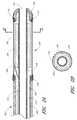
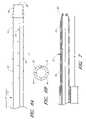
- FIG. 1is a side view of an ultrasonic catheter that is particularly well-suited for use in small vessels of the distal anatomy.
- FIG. 2Ais a cross-sectional view of the distal end of the ultrasonic catheter of FIG. 1 .
- FIG. 2Bis a cross-sectional view of the ultrasonic catheter of FIG. 2A taken through line 2 B- 2 B.
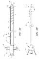
- FIG. 3Ais side elevation view of one embodiment of an ultrasonic catheter which is particularly well-suited for treating long segment peripheral arterial occlusions, such as those occasionally found in the arteries of the leg.
- FIG. 3Bis a side elevation view of an inner core configured for use with the ultrasonic catheter of FIG. 3A .
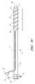
- FIG. 3Cis a side elevation view of a modified embodiment of an ultrasonic catheter.
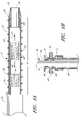
- FIG. 4Ais a cross-sectional view of a distal end of the ultrasonic catheter of FIG. 3A .
- FIG. 4Bis a cross-sectional view of a proximal end of the ultrasonic catheter of FIG. 3A .
- FIG. 4Cis a cross-sectional view of another modified embodiment of an ultrasonic catheter.
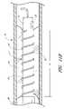
- FIG. 5Ais a side view of the distal end of the ultrasonic catheter of FIG. 3A .
- FIG. 5Bis a cross-sectional view of the distal end of the ultrasonic catheter of FIG. 5A taken through line 5 B- 5 B.
- FIG. 5Cis a side view of a modified embodiment of the distal end of an ultrasonic catheter.
- FIG. 5Dis a cross-sectional view of the distal end of the ultrasonic catheter of FIG. 5C taken along line 5 D- 5 D.
- FIG. 5Eis a side view of another modified embodiment of the distal end of an ultrasonic catheter.
- FIG. 5Fis a side view yet of another modified embodiment of the distal end of an ultrasonic catheter.
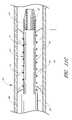
- FIG. 6Ais a side view of yet another modified embodiment of the distal end of an ultrasonic catheter which includes drug delivery ports of increasing size.
- FIG. 6Bis a cross-sectional view of the distal end of an ultrasonic catheter wherein the proximal and distal ends are made of different materials.
- FIG. 7is a cross-sectional view of a distal end of an ultrasonic catheter that includes an integral occlusion device.
- FIG. 8Aillustrates a wiring diagram for connecting a plurality of ultrasound radiating members in parallel.
- FIG. 8Billustrates a wiring diagram for connecting a plurality of ultrasound radiating members in series.
- FIG. 8Cillustrates a wiring diagram for connecting a plurality of ultrasound radiating members with a common wire.
- FIG. 9a wiring diagram for connecting a plurality of temperature sensors with a common wire.
- FIG. 10is a block diagram of a feedback control system for use with an ultrasonic catheter
- FIG. 11Ais a cross-sectional view of a treatment site.
- FIG. 11Bis a side view of the distal end of an ultrasonic catheter positioned at the treatment site.
- FIG. 11Cis a cross-sectional view of the distal end of the ultrasonic catheter of FIG. 11B positioned at the treatment site.
- FIG. 11Dis a side view of the proximal end of the ultrasonic catheter of FIG. 11B .
- FIG. 11Eis a cross-sectional view of the distal end of the ultrasonic catheter of FIG. 11B positioned at the treatment site.
- FIG. 11Fis a cross-sectional view of the distal end of the ultrasonic catheter of FIG. 11B positioned at the treatment site showing the movement of the inner core.
- FIG. 11Gis a side view of the distal end of the ultrasonic catheter of FIG. 11B positioned at the treatment site.
- FIG. 12Ais a perspective view of an ultrasound radiating member having pentagonal front and rear faces.
- FIG. 12Bis a perspective view of an ultrasound radiating member having hexagonal front and rear faces.
- FIG. 12Cis a perspective view of an ultrasound radiating member having octagonal front and rear faces.
- FIG. 12Dis a perspective view of an ultrasound radiating member having triangular front and rear faces.
- FIG. 12Eis a perspective view of an ultrasound radiating member having rectangular front and rear faces.
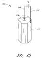
- FIG. 13is a perspective view of an ultrasound radiating member having first and second wires connected to inner and outer surfaces, respectively.
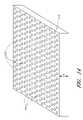
- FIG. 14is a perspective view of a sheet of piezoelectric material perforated with through or blind holes.
- FIG. 15Ais a plan view of the piezoelectric sheet of FIG. 14 having been cut to produce ultrasound radiating members having a hexagonal geometry.
- FIG. 15Bis a plan view of the piezoelectric sheet of FIG. 14 having been cut to produce ultrasound radiating members having a octagonal geometry.
- FIG. 16is a cross-sectional view of the cut piezoelectric sheet of FIG. 15A or 15 B.
- FIG. 17is a cross-sectional view of the piezoelectric sheet of FIG. 16 , illustrating a method of harvesting individual ultrasound radiating members.
- ultrasonic catheterscan be used to enhance the effect and/or delivery of a therapeutic compound.
- therapeutic compoundrefers, in addition to its ordinary meaning, to drugs, biological macromolecules (including, but not limited to, proteins and nucleic acids), and other pharmacological agents, including combinations thereof. Exemplary applications of ultrasonic catheters are provided in U.S. Pat. Nos. 5,318,014, 5,362,309, 5,474,531, 5,628,728, 6,001,069, and 6,210,356.
- an ultrasonic catheteris adapted for use in the treatment of thrombus in the small blood vessels or arteries of the human body, such as, for example, the small cerebral arteries.
- an ultrasonic catheteris adapted for use in the treatment of thrombus in larger blood vessels or arteries of the human body such as those located in the lower leg.
- the ultrasonic catheters disclosed hereincan also be used in other therapeutic applications, such as performing gene therapy (see, for example, U.S. Pat. No. 6,135,976), activating light activated drugs used to cause targeted tissue death (see, for example, U.S. Pat. No. 6,176,842) and causing cavitation to produce biological effects (see, for example, U.S.
- the ultrasonic catheters disclosed hereincan be used in applications where the ultrasonic energy provides a therapeutic effect by itself.
- ultrasonic energycan provide and/or reduce stenosis and/or restenosis; tissue ablation, abrasion or disruption; promotion of temporary or permanent physiological changes in intracellular or intercellular structures; and/or rupture of micro-balloons or micro-bubbles for therapeutic compound delivery. See, for example, U.S. Pat. Nos. 5,269,291 and 5,431,663.
- the methods and apparatuses disclosed hereincan also be used in applications that do not require the use of a catheter, such as, enhancement of hyperthermic drug treatment, use of externally generated ultrasonic energy to enhance the effect and/or delivery of a therapeutic compound at a specific site within the body, and use of ultrasonic energy to provide a therapeutic or diagnostic effect by itself. See, for example, U.S. Pat. Nos. 4,821,740, 4,953,565, 5,007,438 and 6,096,000.
- ultrasonic energyis used broadly, and encompasses its ordinary definition, as well as mechanical energy transferred through longitudinal pressure or compression waves with a frequency greater than about 20 kHz and less than about 20 MHz.
- the waveshave a frequency between about 500 kHz and 20 MHz, and in another embodiment the waves have a frequency between about 1 MHz and 3 MHz. In yet another embodiment, the waves have a frequency of about 3 MHz.
- catheteris used broadly, and encompasses its ordinary definition, as well as flexible tubes configured to be inserted into a body cavity, duct or vessel.
- FIGS. 1 , 2 A and 2 Billustrate an exemplary embodiment of an ultrasonic catheter 100 that is particularly well-suited for use in small vessels of the distal anatomy, such as in small neurovascular vessels in the brain.
- the ultrasonic catheter 100generally comprises a multi-component tubular body 102 having a proximal end 104 and a distal end 106 .
- the tubular body 102 and other components of the catheter 100can be manufactured in accordance with conventional catheter manufacturing techniques. Suitable dimensions can be readily selected based on the dimensions of the treatment site and the desired percutaneous access site.
- the tubular body 102is elongate and flexible, and comprises an outer sheath 108 (illustrated in FIG. 2A ) that is positioned over an inner core 110 .
- the outer sheath 108can comprise extruded polytetrafluoroethylene (“PTFE”), polyetheretherketone (“PEEK”), polyethylene (“PE”), polymides, braided polymides and/or other similar materials.
- PTFEpolytetrafluoroethylene
- PEEKpolyetheretherketone
- PEpolyethylene
- the outer sheath 108has an outer diameter of approximately 0.039 inches at its proximal end and between approximately 0.033 and approximately 0.039 inches at its distal end.
- the outer sheath 108has an axial length of approximately 150 centimeters.
- the outer sheath 108can be formed from a braided tubing comprising high or low density polyethylenes, urethanes, nylons, and so forth. Such configurations enhance the flexibility of the tubular body 102 .
- the outer sheath 108can include a stiffening member (not shown) at the tubular body proximal end 104 .
- the inner core 110at least partially defines a central lumen 112 , or “guidewire lumen,” which preferably extends through the length of the catheter 100 .
- the central lumen 112has a distal exit port 114 and a proximal access port 116 .
- the proximal access port 116is defined by therapeutic compound inlet port 117 on a back end hub 118 , which is attached to the outer sheath proximal end 104 .
- the back end hub 118is attached to a control box connector 120 , which described in greater detail below.
- the central lumen 112is configured to receive a guidewire (not shown) having a diameter of between approximately 0.010 includes to approximately 0.012 inches.
- the inner core 110is formed from polymide or a similar material, which can optionally be braided to increase the flexibility of the tubular body 102 .
- the distal end 106 of the tubular body 102includes an ultrasound radiating member 124 .
- the ultrasound radiating member 124comprises an ultrasonic transducer, which converts, for example, electrical energy into ultrasonic energy.
- the ultrasound radiating member 124is in the shape of a hollow cylinder as is conventional in the prior art. Improved radiating members 124 will be described in FIGS. 12 through 17 below.
- the inner core 110extends through the ultrasound radiating member 124 , which is positioned over the inner core 110 .
- the ultrasound radiating member 124can be secured to the inner core 110 in a suitable manner, such as with an adhesive. Extending the core through the member 124 advantageously provides enhanced cooling of the ultrasound radiating member 124 .
- a therapeutic compoundcan be injected through the central lumen 112 , thereby providing a heat sink for heat generated by the ultrasound radiating member 124 .
- suitable operating frequencies for the ultrasound radiating member 124include, but are not limited to, from about 20 kHz to less than about 20 MHz. In one embodiment, the frequency is between about 500 kHz and about 20 MHz, and in another embodiment the frequency is between about 1 MHz and about 3 MHz. In yet another embodiment, the ultrasonic energy has a frequency of about 3 MHz.
- ultrasonic energyis generated by supplying electrical power to the ultrasound radiating member 124 .
- the electrical powercan be supplied through the controller box connector 120 , which is connected to a first electrically conductive wire 126 and a second electrically conductive wire 128 .
- the wires 126 , 128extend through the catheter body 102 .
- the wires 126 , 128are secured to the inner core 110 , lay along the inner core 110 and/or extend freely in the space between the inner core 110 and the outer sheath 108 .
- the first wire 126is connected to the hollow center of the ultrasound radiating member 124 , while the second wire 128 is connected to the outer periphery of the ultrasound radiating member 124 .
- the ultrasound radiating member 124comprises a piezoelectric ceramic oscillator; in other embodiments, the ultrasound radiating member 124 comprises other similar materials.
- the catheter 10may include more than one ultrasound radiating member 124 .
- the ultrasound radiating membersmay be electronically connected in series or parallel as described above and in more detail below.
- the distal end of the catheter 100includes sleeve 130 , which is generally positioned about the ultrasound radiating member 124 .
- the sleeve 130comprises a material that readily transmits ultrasonic energy.
- Suitable materials for the sleeve 130include, but are not limited to, polyolefins, polyimides, polyesters and other low ultrasound impedance materials.
- Low ultrasound impedance materialsare materials that readily transmit ultrasonic energy with minimal absorption of the ultrasonic energy.
- the proximal end of the sleeve 130can be attached to the outer sheath 108 with an adhesive 132 .
- the distal end of the sleeve 130can be attached to a catheter tip 134 .
- the tip 134is generally rounded and is also attached to the distal end of the inner core 110 .
- the tubular body 102is divided into at least three sections of varying stiffness.
- the first sectionwhich includes the proximal end 104 , is generally more stiff than a second section, which lies between the proximal end 104 and the distal end 106 .
- This arrangementfacilitates the movement and placement of the catheter 100 within small vessels.
- the third sectionwhich includes ultrasound radiating element 124 , is generally stiffer than the second section due to the presence of the ultrasound radiating element 124 .
- the catheter 100includes at least one temperature sensor 136 that is located at or near the distal end of the catheter 100 , and near the ultrasound radiating member 124 .
- Suitable temperature sensorsinclude, but are not limited to, diodes, thermistors, thermocouples, resistance temperature detectors (“RTD”), and fiber optic temperature sensors that use thermalchromic liquid crystals.
- the temperature sensorsare operatively connected to a control box (not shown) through a control wire that extends through the tubular body 102 and back end hub 118 , and that is operatively connected to a control box through the control box connector 120 .
- control boxincludes a feedback control system, such as the control system described herein.
- control boxis configured to monitor and control the power, voltage, current and phase of the signal supplied to the ultrasound radiating members 124 . This configuration allows the temperature of the catheter to be monitored and controlled.
- a free end of a guidewireis percutaneously inserted into the arterial system at a suitable insertion site.
- the guidewireis advanced through the vessels towards a treatment site, which includes, for example, a clot.
- the guidewireis directed through the clot.
- the catheter 100is then percutaneously inserted through the insertion site and advanced along the guidewire towards the treatment site using conventional over-the-guidewire techniques.
- the catheter 100is advanced until the distal end of the catheter 100 is positioned at or within the clot.
- the catheter distal endincludes radiopaque markers to aid in positioning the catheter at the treatment site.
- Suitable therapeutic compounds for treating thrombusinclude, but are not limited to, aqueous solutions containing a thrombolytic agent (that is, a clot-dissolving drug), such as, heparin, urokinase, streptokinase, TPA and BB-10153, which is manufactured by British Biotech (Oxford, United Kingdom).
- a thrombolytic agentthat is, a clot-dissolving drug
- other agentscan be delivered through the central lumen.
- Such other agentsinclude, but are not limited to, cancer treating drugs, genetic material, light activated drugs, and so forth.
- the ultrasound radiating member 124is activated to deliver ultrasonic energy through the distal end of the catheter 100 to the treatment site.
- suitable frequencies for the ultrasound radiating member 124include, but are not limited to, from about 20 kHz to less than about 20 MHz. In one embodiment, the frequency is between about 500 kHz and about 20 MHz, and in another embodiment the frequency is between about 1 MHz and about 3 MHz. In yet another embodiment, the ultrasonic energy has a frequency of about 3 MHz.
- the therapeutic compound and ultrasonic energycan be applied until the clot is partially or entirely dissolved. Once the clot has been dissolved to the desired degree, the catheter 100 can be withdrawn from the treatment site.
- the catheter 100includes a cooling system for removing heat generated by the ultrasound radiating member 124 .
- a return pathcan be formed in region 138 , such that coolant from a coolant system can be directed through region 138 (see FIG. 2A ).
- FIGS. 3A and 3Billustrate one embodiment of an ultrasonic catheter 10 , which is particularly well-suited for treating long segment peripheral arterial occlusions, such as those occasionally found in the arteries of the leg.
- the ultrasonic catheter 10generally comprises a multi-component tubular body 12 having a proximal end 14 and a distal end 15 .
- the tubular body 12 and other components of the catheter 10can be manufactured in accordance with any of a variety of conventional catheter manufacturing techniques. Suitable dimensions for the catheter components can be readily selected based on the natural and anatomical dimensions of the treatment site and of the desired percutaneous insertion site.
- the tubular body 12is elongate and flexible, and comprises an outer sheath 16 .
- the outer sheath 16preferably includes a support section 17 located at the proximal end and an energy delivery section 18 located at the distal end of the catheter 10 .
- the support section 17comprises extruded PTFE, PEEK, PE and/or similar materials that provide the outer sheath 16 with enough flexibility, kink resistance, rigidity and structural support necessary to push the energy delivery section 18 to a treatment site.
- the outer sheath 16has an outside diameter of approximately 0.060 inches to approximately 0.075 inches. In such, an embodiment, the outer sheath 16 has an axial length of approximately 90 centimeters.
- the energy delivery section 18 of the outer sheath 16comprises a relatively thin material compared to the support section 17 .
- a thinner materialadvantageously increases the acoustic transparency of the energy delivery section 18 .
- Suitable materials for the energy delivery section 18include, but are not limited to, high or low density polyethylenes, urethanes, nylons, and so forth.
- the outer sheath 16defines a utility lumen 28 that extends through the length of the catheter 10 .
- the utility lumen 28has a distal exit port 29 and a proximal access port 31 .
- the proximal access port 31is defined by a backend hub 33 , which is attached to the proximal end of the outer sheath 16 .
- a delivery lumen 30is positioned adjacent the energy delivery section 18 .
- the delivery lumen 30includes an inlet port 32 , which is formed in the backend hub 33 and is coupled to a therapeutic compound source via a hub such as a Luer type fitting.
- the delivery lumen 30can be incorporated into the support section 17 (as illustrated in FIG. 3A ) or can be external to the support section (as illustrated in FIG. 3C ).
- the catheter 10also includes an elongated inner core 34 (see FIG. 3B ) having a proximal end 36 and a distal end 38 .
- An ultrasound radiating member 40is positioned at or near the core distal end 38 .
- Further information regarding methods and structures for mounting ultrasound radiating members within the inner corecan be found in Applicant's co-pending U.S. patent application Ser. No. 10/309,388, which is hereby incorporated herein by reference in its entirety.
- a plurality of ultrasound radiating memberssuch as the ultrasound radiating members disclosed herein and illustrated in FIGS. 12 through 17 , can be mounted within the inner core.
- the ultrasound radiating memberscan be electrically connected in series or in parallel.
- the inner core 34has an outer diameter which permits the inner core 34 to be inserted into the utility lumen 28 via the proximal access port 31 .
- FIG. 4Aillustrates the inner core 34 inserted inside the utility lumen 28 with an ultrasound radiating member 40 is positioned within the energy delivery section 18 .
- Suitable outer diameters of the inner core 34include, but are not limited to, between approximately 0.010 inches and approximately 0.100 inches.
- Suitable diameters of the utility lumen 28include, but are not limited to between approximately 0.015 inches and approximately 0.110 inches.
- the ultrasound radiating member 40can be rotated or moved within the energy delivery section 18 as illustrated by the arrows 52 in FIG. 4A .
- the ultrasound radiating member 40can be moved within the energy delivery section 18 by manipulating the inner core proximal end 36 while holding the backend hub 33 stationary.
- the inner core 34is at least partially constructed from a material that provides enough structural support to permit movement of the inner core 34 within the outer sheath 16 without causing the outer sheath 16 to kink. Suitable materials for the inner core 34 include, but are not limited to, polyimides, polyesters, polyurethanes, thermoplastics, elastomers, and braided wires with fiber reinforcement.
- the outer diameter of the inner core 34can be smaller than the inner diameter of the utility lumen 28 , thereby creating a cooling fluid lumen 44 between the inner core 34 and the utility lumen 28 .
- a cooling fluidcan flow through the cooling fluid lumen 44 , past the ultrasound radiating members 40 and through the distal exit port 29 .
- Cooling fluidcan be supplied via a cooling fluid fitting 46 provided on the backend hub 33 shown in FIG. 3A .
- the cooling fluid flow rate and/or the power to the ultrasound radiating members 40can be adjusted to maintain the temperature of the ultrasound radiating member 40 within a specified range.
- the cooling fluidcan be flowed from the cooling fluid fitting 46 through the cooling fluid lumen 44 as illustrated by arrows 48 .
- the cooling fluid fitting 46optionally includes a hemostasis valve 50 having an inner diameter that substantially matches the diameter of the inner core 34 . The matched diameters reduce leaking of the cooling fluid between the cooling fluid fitting 46 and the inner core 34 .
- the ultrasound radiating member 40comprises a hollow cylinder, and the inner core 34 defines a central lumen 51 , which extends through the ultrasound radiating member 40 .
- the cooling fluidflows through the central lumen 51 , and past and through the ultrasound radiating member 40 , thereby providing cooling to the ultrasound radiating member 40 .
- the cooling fluidcan be supplied via the proximal access port 31 , with the cooling fluid fitting 46 and hemostasis valve 50 providing a seal between the inner core 34 and the outer sheath 16 .
- the sheath 16can be closed at the catheter distal end, thereby providing a system for recirculating cooling fluid, and for preventing cooling fluid from entering the patient's vascular system.
- the catheter 10includes an occlusion device 22 positioned at the distal end of the catheter 10 .
- the utility lumen 28extends through the occlusion device 22 .
- the portion of the utility lumen 28 extending through the occlusion device 22has a diameter that can accommodate a guidewire (not shown) but that prevents the ultrasound radiating member 40 from passing through the occlusion device 22 .
- Suitable inner diameters for the occlusion device 22include, but are not limited, to between approximately 0.005 inches and approximately 0.050 inches.
- the delivery lumen 30includes a therapeutic compound delivery portion that is positioned adjacent the energy delivery section 18 .
- the delivery lumen 30is wound around the tubular body 12 in the energy delivery section 18 .
- the delivery lumen 30includes a series of delivery ports 58 .
- a therapeutic compound source coupled to the inlet port 32can provide a pressure which drives the therapeutic compound through the delivery lumen 30 and out the delivery ports 58 .
- a suitable material for the delivery lumen 30includes, but is not limited to, high or low density polyethylenes, urethanes, nylons, and so forth.
- the catheter 10can include a plurality of delivery lumens 30 .
- the delivery lumens 30can be wound around the energy delivery section 18 or they can be positioned along the length of the energy delivery section 18 as illustrated in FIGS. 5C and 5D .
- Each delivery lumen 30can be coupled to the same drug inlet port 32 , or each delivery lumen 30 can be coupled to an independent drug inlet port 32 , thus allowing different therapeutic compound solutions to be delivered to different delivery ports 58 .
- the delivery ports 58are positioned close enough to achieve a substantially even flow of therapeutic compound solution around the circumference of the energy delivery section 18 , and along the length of the energy delivery section 18 .
- the proximity of adjacent delivery ports 58can be changed by changing the density of delivery ports 58 along the delivery lumen 30 , by changing the number of windings of the delivery lumen 30 around the energy delivery section 18 , or by changing the number of delivery lumens 30 positioned along the energy delivery section 18 .
- the windings of the delivery lumens 30has a pitch that ranges from about one spiral per one centimeter to about one spiral per 20 centimeters.
- the size of the delivery ports 58can be the same or can vary along the length of the delivery lumen 30 .
- the size of the delivery ports 58 along the distal portion of the energy delivery section 18are larger than the delivery ports 58 along the proximal portion of the energy delivery section 18 .
- the increase in size of the delivery ports 58can be configured to produce similar flow rates of therapeutic compound solution through each delivery port 58 .
- a similar flow rateincreases the uniformity of therapeutic compound solution flow rate along the length of the outer sheath 16 .
- the delivery ports 58have a diameter of between approximately 0.0005 inches and approximately to 0.0050 inches.
- the delivery ports 58have a diameter of between approximately 0.0001 inches and approximately 0.005 inches at the proximal end and between about 0.0005 inches and approximately 0.020 inches at the distal end.
- the increase in size between adjacent delivery ports 58can be substantially uniform between along the delivery lumen 30 .
- the dimensional increase of the delivery ports 58can be dependent upon the material and the diameter of the delivery lumen 30 .
- the delivery ports 58can be punched, drilled, burnt with a laser, and so forth, into the delivery lumen 30 .
- Uniformity of the drug solution flow along the length of the outer sheath 16can also be increased by increasing the density of the delivery ports 58 toward the distal end of the delivery lumen 30 .
- the delivery ports 58can be slits with a straight shape (as illustrated in FIG. 5E ) or an arcuate shape (as illustrated in FIG. 5F ).
- the delivery lumen 30can be constructed from materials such as polyimide, nylon, Pebax®, polyurethane or silicon. When the delivery lumen 30 contains drug solution, the slits remain closed until the pressure within the delivery lumen 30 exceeds a threshold pressure, where the pressure on each of the slit-shaped delivery ports 58 is approximately uniform.
- the slit-shaped delivery ports 58will open almost simultaneously, resulting in a nearly uniform flow of therapeutic compound solution from the slits.
- the slit-shaped delivery ports 58close and prevent delivery of additional therapeutic compound solution.
- the slit shapecan also prevent the delivery ports 58 from opening when exposed to low pressures from outside the outer sheath 16 . As a result, slit shaped delivery ports 58 can enhance control of therapeutic compound delivery.
- the outer sheath 16 and energy delivery section 18are constructed from a single material. Suitable materials include, but are not limited to, high or low density polyethylenes, urethanes, nylons, and so forth.
- the entire outer sheath 16 , or only the outer sheath proximal end,can be reinforced by braiding, mesh or other constructions to increase the ability of the catheter to be pushed through a patient's vasculature (“pushability”).
- the delivery ports 58can be incorporated into the outer sheath 16 .
- the delivery ports 58can be coupled with independent delivery lumens 30 formed within the outer sheath 16 , as illustrated in FIG. 6B .
- the outer sheath 16includes a support section 17 that is constructed from a different material than the energy delivery section 18 .
- the energy delivery section 18can be constructed from a material which readily transmits ultrasound energy.
- the support section 17can be constructed from a material which provides structural strength and kink resistance. Further, the support section 17 , or the proximal end of the support section 17 , can be reinforced by braiding, mesh or other constructions to increase kink resistance and pushability.
- Suitable materials for the support section 17include, but are not limited to PTFE, PEEK, PE and/or similar materials.
- Suitable outer diameters for the support section 17include, but are not limited to between approximately 0.020 inches and approximately 0.200 inches.
- Suitable materials for the energy delivery section 18include, but are not limited to high or low density polyethylenes, urethanes, nylons, and other materials that produce minimal ultrasound attenuation. Such materials readily transmit ultrasound energy with minimal absorption of the ultrasound energy.
- FIG. 7also illustrates an occlusion device 22 that is integrally formed with the energy delivery section 18 .
- the ultrasound radiating memberscomprise ultrasonic transducers configured to convert, for example, electrical energy into ultrasonic energy.
- An exemplary ultrasonic transducer for generating ultrasonic energy from electrical energyincludes is a piezoelectric ceramic oscillator.
- the ultrasonic energycan be generated by an ultrasonic transducer that is remote from the ultrasound radiating members, and the ultrasonic energy can be transmitted to the ultrasound radiating members via a wire, for example.
- the ultrasound radiating memberscomprise an ultrasonic transducer with a cylindrical shape.
- the ultrasonic transducercan be a block, a hollow cylinder or a disk.
- the ultrasound radiating memberscan optionally be positioned concentrically around the inner core 34 .
- the ultrasound radiating membersare formed of an array of smaller ultrasound radiating members.
- a single ultrasound radiating membercan be formed a combination of several smaller ultrasound radiating members.
- suitable operating frequencies for the ultrasound radiating membersinclude, but are not limited to, from about 20 kHz to less than about 20 MHz. In one embodiment, the frequency is between about 500 kHz and about 20 MHz, and in another embodiment the frequency is between about 1 MHz and about 3 MHz. In yet another embodiment, the ultrasonic energy has a frequency of about 3 MHz.
- ultrasound radiating membercan be individually powered.
- the catheterincludes n ultrasound radiating members, the catheter will also include 2n wires to individually power n ultrasound radiating members.
- the ultrasound radiating members 40can be electrically coupled in serial or in parallel, as illustrated in FIGS. 8A and 8B . These arrangements permit more flexibility as they use fewer wires.
- Each of the ultrasound radiating memberscan receive power simultaneously whether the ultrasound radiating members are in series or in parallel. When the ultrasound radiating members are connected in series, less current is required to produce the same power from each ultrasound radiating member than when the ultrasound radiating members are connected in parallel.
- the reduced currentallows smaller wires to be used to provide power to the ultrasound radiating members, and accordingly increases the flexibility of the catheter.
- an ultrasound radiating membercan fracture or otherwise fail without breaking the current flow and interrupting the operation of the other ultrasound radiating members.
- the output power of the ultrasound radiating memberscan be controlled.
- a common wire 61can provide power of plurality of ultrasound radiating members 40 , while each ultrasound radiating member 40 has its own return wire 62 .
- a particular ultrasound radiating member 40can be individually activated by closing a switch 64 to complete a circuit between the common wire 61 and the return wire 62 associated with the particular ultrasound radiating member 40 .
- the amount of power supplied to the ultrasound radiating member 40can be adjusted using a potentiometer 66 .
- a catheter with n ultrasound radiating members 40uses only n+1 wires, and still permits independent control of the ultrasound radiating members 40 .
- This reduced number of wiresincreases the flexibility of the catheter.
- the individual return wires 62can have diameters which are smaller than the common wire 61 diameter. For instance, in an embodiment where n ultrasound radiating members are powered simultaneously, the diameter of the individual return wires 62 can be approximately the square root of n times smaller than the diameter of the common wire 61 .
- the catheterfurther includes one or more temperature sensors 20 located at the catheter distal end.
- the small vessel catheter illustrated in FIG. 2Balso optionally includes a temperature sensor 136 .
- the inner core proximal end 36includes a temperature sensor lead 24 , which is operatively connected to the temperature sensors 20 .
- the temperature sensors 20are positioned in the energy delivery section 18 on the surface of the outer sheath 16 .
- the temperature sensor lead 24extends from the outer sheath proximal end.
- Suitable temperature sensors 20include, but are not limited to, temperature sensing diodes, thermistors, thermocouples, RTDs, and fiber optic temperature sensors which use thermalchromic liquid crystals.
- Suitable temperature sensor 20 geometriesinclude, but are not limited to, a point, patch, a stripe, and a band around the outer sheath 16 .
- the temperature sensors 20can be positioned on the outer sheath 16 or on the inner core 34 near the ultrasound radiating members 40 . In an exemplary embodiment, the temperature sensors 20 are positioned near the energy delivery section 18 .
- the temperature sensors 20can be electrically connected as illustrated in FIG. 9 .
- Each temperature sensor 20can be coupled with a common wire 61 and an individual return wire 62 . Accordingly, n+1 wires can be used to independently sense the temperature at n temperature sensors 20 .
- the temperature at a particular temperature sensor 20can be determined by closing a switch 64 to complete a circuit that includes the particular temperature sensor 20 .
- the temperature sensors 20are thermocouples, the temperature can be calculated from the voltage in the circuit using, for example, a sensing circuit 63 .
- the individual return wires 62can have diameters which are smaller than the diameter of the common wire 61 .
- Each temperature sensor 20can also be independently wired.
- n independently wired temperature sensors 20use 2n wires along the outer sheath 16 .
- the flexibility of the outer sheath 16 and inner core 34can also be improved by using fiber optic based temperature sensors 20 . Particularly, in such embodiments only n fiber optics are used to sense the temperature at n temperature sensors 20 .
- the catheter 10can be used with a feedback control system 68 , as illustrated in FIG. 10 .
- the temperature at each temperature sensor 20is monitored, and the output power of the energy source 70 is adjusted accordingly.
- the physiciancan, if desired, override the closed or open loop system.
- the feedback control system 68includes an energy source 70 , a power circuit 72 , and a power calculation device 74 coupled with the ultrasound radiating members 40 .
- a temperature measurement device 76is coupled with the temperature sensors 20 on the outer sheath 16 or the inner core 34 .
- a processing unit 78is coupled with the power calculation device 74 , the power circuits 72 , and a user interface and display 80 .
- the temperature at the temperature sensors 20is determined at the temperature measurement device 76 .
- the processing unit 78receives the determined temperatures from the temperature measurement device 76 .
- the determined temperaturescan then be displayed to the user at the user interface and display 80 .
- the processing unit 78includes logic for generating a temperature control signal.
- the temperature control signalis proportional to the difference between the measured temperature and a desired temperature.
- the desired temperaturecan be determined by the user or be preset within the processing unit 78 .
- the usersets the desired temperature using the user interface and display 80 .
- the temperature control signalis received by the power circuit 72 .
- the power circuit 72can be configured to adjust the power level, voltage, phase and/or current of the energy supplied to the ultrasound radiating members 40 from the energy source 70 . For instance, when the temperature control signal is above a particular level, the power supplied to a particular ultrasound radiating member 40 can be reduced in response to the temperature control signal. Similarly, when the temperature control signal is below a particular level, the power supplied to a particular ultrasound radiating member 40 can be increased in response to the magnitude of the temperature control signal.
- the processing unit 78monitors the temperature sensors 20 and produces another temperature control signal which is received by the power circuits 72 .
- the processing unit 78can also include safety control logic.
- the safety control logicdetects when the temperature at a temperature sensor 20 has exceeded a safety threshold.
- the processing unit 78can then provide a temperature control signal which causes the power circuit 72 to reduce or stop the delivery of energy from the energy source 70 to the ultrasound radiating members 40 .
- each ultrasound radiating member 40is identically adjusted in one embodiment.
- the power, voltage, phase, and/or current supplied to each of the ultrasound radiating members 40is adjusted in response to the temperature sensor 20 which indicates the highest temperature. Making voltage, phase and/or current adjustments in response to the temperature of the temperature sensor 20 indicating the highest temperature can reduce the likelihood that the treatment site overheats.
- the processing unit 78can be configured to receive a power signal from the power calculation device 74 .
- the power signalcan be used to determine the power being received by each ultrasound radiating member 40 .
- the determined powercan then be displayed to the user on the user interface and display 80 .
- the feedback control system 68can maintain the treatment site within a desired temperature range. For example, to prevent the temperature of the treatment site from increasing more than 6° C. above body temperature, and thus causing tissue damage, the ultrasound radiating members 40 can be independently monitored and controlled as described above.
- the processing unit 78can be preprogrammed to drive each ultrasound radiating member 40 at a predetermined energy for a predetermined length of time.
- the processing unit 78can comprise a digital or analog controller, or a computer with software. In embodiments wherein the processing unit 78 is a computer, it can include a central processing unit coupled through a system bus.
- the user interface and display 80can comprise a mouse, keyboard, a disk drive or other non-volatile memory system, a display monitor, and other peripherals. Program memory and data memory can also be coupled to the bus.
- a profile of the power to be delivered to each ultrasound radiating member 40can be incorporated in the processing unit 78 .
- a preset amount of energy to be deliveredcan also be profiled.
- the power delivered to each ultrasound radiating member 40can the be adjusted according to the profiles.
- FIGS. 11A through 11Gillustrate an exemplary method for using the ultrasonic catheter 10 .
- This methodis applicable to both long segment and small vessel catheters.
- a guidewire 84 similar to a guidewire used in typical angioplasty proceduresis directed through vessels 86 toward a treatment site 88 which includes a clot 90 .
- the guidewire 84is optionally directed through the clot 90 .
- Suitable vesselsinclude, but are not limited to, the large periphery blood vessels of the body.
- the ultrasonic catheter 10can also be used for various imaging applications and for treating and/or diagnosing other diseases in other body parts.
- the outer sheath 16is advanced over the guidewire 84 using over-the-guidewire techniques.
- the outer sheath 16is advanced until the energy delivery section 18 is positioned at the clot 90 .
- Radiopaque markersare optionally positioned at the energy delivery section 18 of the outer sheath 16 to aid in the positioning of the outer sheath 16 within the treatment site 88 .
- the guidewire 84is withdrawn from the utility lumen 28 by pulling the guidewire 84 proximally while holding the outer sheath 16 stationary.
- a temperature monitor 92is coupled with the temperature sensor leads 24
- a cooling fluid source 94is coupled with the cooling fluid fitting 46
- a therapeutic compound solution source 96is coupled with the inlet port 32 .
- the therapeutic compound solution source 96can be a syringe with a Luer fitting that is complementary to the inlet port 32 . Pressure can be applied to a plunger 98 on the therapeutic compound solution source 96 , thereby driving the therapeutic compound through the delivery lumen 30 .
- the therapeutic compoundis delivered from the delivery lumen 30 through the delivery ports 58 as illustrated by the arrows 99 in FIG. 11E .
- Suitable therapeutic compoundsinclude, but are not limited to, an aqueous solution containing a thrombolytic agent (that is, a clot-dissolving drug), such as, heparin, urokinase, streptokinase, TPA and BB-10153.
- a thrombolytic agentthat is, a clot-dissolving drug
- other therapeutic compoundssuch as cancer treating drugs, genetic material, light activated drugs and so forth
- the inner core 34is inserted into the utility lumen 28 until the ultrasound radiating member 40 is positioned within the energy delivery section 18 .
- radiopaque markerscan be affixed to the inner core 34 adjacent the ultrasound radiating members 40 , or the ultrasound radiating members 40 themselves can be radiopaque.
- the ultrasonic energy radiated by the ultrasound radiating members 40can be used to aid placement.
- the ultrasonic energyhas a frequency between approximately 20 kHz and approximately 20 MHz. In another embodiment, the frequency is between about 500 kHz and about 20 MHz. In another embodiment, the frequency is between about 1 MHz and about 3 MHz. In another embodiment, the frequency is about 3 MHz.
- the ultrasound radiating member 40can optionally be moved within the energy delivery section 18 as illustrated by the arrows 52 . The ultrasound radiating member 40 can be moved within the energy delivery section 18 by manipulating the inner core proximal end 36 while holding the backend hub 33 stationary. In the illustrated embodiment, a cooling fluid flows through the cooling fluid lumen 44 and out the occlusion device 22 .
- the cooling fluidcan be delivered before, after, during or intermittently with the delivery of the ultrasonic energy.
- the therapeutic compoundcan be delivered before, after, during or intermittently with the delivery of ultrasonic energy.
- FIGS. 11A through 11Fcan be performed in different orders than are described above.
- the therapeutic compound and energyare applied until the clot 90 is partially or entirely dissolved, as illustrated in FIG. 11G . Once the clot 90 has been sufficiently dissolved, the outer sheath 16 and inner core 34 are withdrawn from the treatment site 88 .
- the ultrasound radiating memberscomprise an elongate cylinder of piezoelectric material having a hollow core through which materials such as a cooling fluid, a therapeutic compound, or electrical conductors can be passed.
- Such ultrasound radiating member embodimentscan be used with both long segment and small vessel ultrasonic catheters.
- the ultrasound radiating member 200comprises a front face 202 , a rear face (not shown) that is opposite the front face, and a hollow central core 204 that extends along the longitudinal axis of the ultrasound radiating member 200 .
- the front and rear facesform an n-sided polygon.
- the front and rear faceshave five sides and form a pentagon.
- the front and rear faceshave six sides and form a hexagon.
- the front and rear faceshave eight sides and form an octagon.
- FIG. 12Athe front and rear faces have five sides and form a pentagon.
- FIG. 12Bthe front and rear faces have six sides and form a hexagon.
- FIG. 12Cthe front and rear faces have eight sides and form an octagon.
- the front and rear faceshave three sides and form a triangle.
- the front and rear faceshave four sides and form a square.
- the sides of the front and rear facesare connected by generally rectangular side faces 206 , which together form the outer surface of the ultrasound radiating member 200 .
- the ultrasound radiating member 200comprises a piezoelectric ceramic or a similar material.
- the side faces 206 and the central core 204are coated with a conductive material.
- the conductive materialcan be applied using an appropriate application technique, such as electroplating.
- a first wire 208is attached to the central core 204
- a second wire 210is connected to at least one of the side faces 206 .
- application of a voltage difference 212 across the first and second wirescauses the ultrasound radiating member 200 to generate ultrasonic energy.
- the ultrasound radiating member 200is mounted directly on an elongate member that extends through the central core 204 .
- This configurationis particularly advantageous in applications where a plurality of ultrasound radiating members are to be mounted within the inner core 34 , as disclosed herein and as illustrated in FIGS. 3B and 4A .
- the ultrasound radiating memberscan be electrically connected in series or in parallel.
- a common wireruns through, and is electrically connected to, the centers of several ultrasound radiating members, and a second wire runs along, and is electrically connected to, the side faces of the ultrasound radiating members.
- an electrically insulating coreruns through the centers of several ultrasound radiating members, and a wire connects the inner electrode and the outer electrode of adjacent ultrasound radiating members.
- the ultrasound radiating memberscan be electrically grouped, such that a separate groups of ultrasound radiating members can be individually activated.
- the embodiments disclosed hereinadvantageously allow a plurality of ultrasound radiating members to be mounted within an inner core 34 that is configured to be inserted into the tubular body of an ultrasonic catheter.
- the ultrasound radiating members illustrated in FIGS. 12A through 12Eare particularly well suited for such applications, because structural members, electrical members, and/or fluids can be passed through the central core 204 .
- the ultrasound radiating members 200 illustrated in FIGS. 12A through 12Ehave several advantages. For example, such ultrasound radiating members 200 have more radiating faces and thus produce a more radially uniform distribution of ultrasound energy as compared to a rectangular block or flat plate. Moreover, as compared to cylindrical ultrasound members, the ultrasound radiating members 200 described herein have a larger output region and have lower mechanical stresses during operation. Lower mechanical stresses during operation result in lower failure rates.
- modified embodiments of the ultrasound radiating members 200have side faces 206 that are non-rectangular (for example, square or tapered) and/or not identical.
- a sheet 214 of piezoelectric ceramic or similar materialis provided.
- the sheet 214has a thickness t that is greater than the length of the finished ultrasound radiating member.
- a plurality of holes 216are then drilled into the sheet 214 .
- the holes 216are drilled in a uniform pattern.
- the holes 216are through holes, which extend through the sheet 214 .
- the holes 216are blind holes that do not extend through the sheet 214 .
- the blind holesare drilled to a depth that is greater than the length of the finished ultrasound radiating member.
- the perforated sheet 214is then diced with a dicing blade or other precision cutting tool to produce an n-sided polygonal geometry.
- a pattern of cuts 218are used to produce a hexagonal ultrasound radiating member 220 centered about each hole 216 .
- the pattern of cuts 218produces an octagonal ultrasound radiating member 222 that is centered about each hole 216 .
- the cuts 218can be arranged to form other polygons with more or fewer sides, such as, triangles, squares, and pentagons.
- the triangular geometry, illustrated in FIG. 12Dis particularly advantageous because it requires a minimum number of cuts while producing no wasted piezoelectric material.
- the cuts 218do not extend through the piezoelectric sheet 214 .
- the cuts 218do extend through the piezoelectric sheet 214 .
- the holes 216can be drilled deeper than the cuts 218 .
- the upper surface of the sheetwhich includes the interior surfaces of the holes 216 and the interior surfaces of the cuts 218 , are plated with a conductive coating.
- This plating processprovides a conductive coating on the central core 204 and the side faces 206 of the ultrasound radiating members to be harvested from the piezoelectric sheet.
- plating material deposited on the top surface 224 of the sheetcan be removed using a grinding wheel 230 , by milling, or using other methods (for example, by grit blasting).
- the individual ultrasound radiating membersare harvested by using a dicing blade 232 or other precision cutting tool to separate uncut backside material 234 from the cut ultrasound radiating members 200 .
- the dicing blade 232cuts at an angle that is substantially perpendicular to the longitudinal axis of the holes 216 .
- the sheet 214is placed upright, and is cut vertically downward, such that the cut ultrasound radiating members 200 can be caught and removed without being damaged by the dicing blade 232 .
- the dicing blade cutintersects the cuts 218 and the holes 216 , thereby producing finished ultrasound radiating members as illustrated in FIGS. 12A through 12E .
- ultrasound radiating members having the configurations disclosed hereinsubject the piezoelectric material to reduced mechanical stresses during use, which decreases the likelihood of fracture and grain disruption as compared to conventionally manufactured ultrasound radiating members.
- the polygonal ultrasound radiating members described hereinemit ultrasonic energy around a larger effective area, and with an improved output pattern, as compared to conventional cylindrical ultrasound radiating members.
- the methods disclosed hereinare also less complex and less expensive than conventional machining methods. These methods are also particularly useful for manufacturing miniaturized ultrasonic elements.
Landscapes
- Health & Medical Sciences (AREA)
- Engineering & Computer Science (AREA)
- Life Sciences & Earth Sciences (AREA)
- Veterinary Medicine (AREA)
- Animal Behavior & Ethology (AREA)
- Public Health (AREA)
- Surgery (AREA)
- General Health & Medical Sciences (AREA)
- Biomedical Technology (AREA)
- Heart & Thoracic Surgery (AREA)
- Medical Informatics (AREA)
- Molecular Biology (AREA)
- Vascular Medicine (AREA)
- Orthopedic Medicine & Surgery (AREA)
- Nuclear Medicine, Radiotherapy & Molecular Imaging (AREA)
- Mechanical Engineering (AREA)
- Dermatology (AREA)
- Anesthesiology (AREA)
- Hematology (AREA)
- Media Introduction/Drainage Providing Device (AREA)
- Ultra Sonic Daignosis Equipment (AREA)
Abstract
Description
Claims (7)
Priority Applications (1)
| Application Number | Priority Date | Filing Date | Title |
|---|---|---|---|
| US12/371,544US7818854B2 (en) | 2002-10-14 | 2009-02-13 | Ultrasound radiating members for catheter |
Applications Claiming Priority (4)
| Application Number | Priority Date | Filing Date | Title |
|---|---|---|---|
| US41840002P | 2002-10-14 | 2002-10-14 | |
| US10/684,845US6921371B2 (en) | 2002-10-14 | 2003-10-14 | Ultrasound radiating members for catheter |
| US11/143,518US7509715B2 (en) | 2002-10-14 | 2005-06-02 | Method of manufacturing ultrasound radiating members for a catheter |
| US12/371,544US7818854B2 (en) | 2002-10-14 | 2009-02-13 | Ultrasound radiating members for catheter |
Related Parent Applications (1)
| Application Number | Title | Priority Date | Filing Date |
|---|---|---|---|
| US11/143,518DivisionUS7509715B2 (en) | 2002-10-14 | 2005-06-02 | Method of manufacturing ultrasound radiating members for a catheter |
Publications (2)
| Publication Number | Publication Date |
|---|---|
| US20090144955A1 US20090144955A1 (en) | 2009-06-11 |
| US7818854B2true US7818854B2 (en) | 2010-10-26 |
Family
ID=32096246
Family Applications (3)
| Application Number | Title | Priority Date | Filing Date |
|---|---|---|---|
| US10/684,845Expired - LifetimeUS6921371B2 (en) | 2002-10-14 | 2003-10-14 | Ultrasound radiating members for catheter |
| US11/143,518Expired - LifetimeUS7509715B2 (en) | 2002-10-14 | 2005-06-02 | Method of manufacturing ultrasound radiating members for a catheter |
| US12/371,544Expired - Fee RelatedUS7818854B2 (en) | 2002-10-14 | 2009-02-13 | Ultrasound radiating members for catheter |
Family Applications Before (2)
| Application Number | Title | Priority Date | Filing Date |
|---|---|---|---|
| US10/684,845Expired - LifetimeUS6921371B2 (en) | 2002-10-14 | 2003-10-14 | Ultrasound radiating members for catheter |
| US11/143,518Expired - LifetimeUS7509715B2 (en) | 2002-10-14 | 2005-06-02 | Method of manufacturing ultrasound radiating members for a catheter |
Country Status (1)
| Country | Link |
|---|---|
| US (3) | US6921371B2 (en) |
Cited By (15)
| Publication number | Priority date | Publication date | Assignee | Title |
|---|---|---|---|---|
| US9044568B2 (en) | 2007-06-22 | 2015-06-02 | Ekos Corporation | Method and apparatus for treatment of intracranial hemorrhages |
| US9415242B2 (en) | 2001-12-03 | 2016-08-16 | Ekos Corporation | Catheter with multiple ultrasound radiating members |
| US9579494B2 (en) | 2013-03-14 | 2017-02-28 | Ekos Corporation | Method and apparatus for drug delivery to a target site |
| US9849273B2 (en) | 2009-07-03 | 2017-12-26 | Ekos Corporation | Power parameters for ultrasonic catheter |
| US9943675B1 (en) | 2002-04-01 | 2018-04-17 | Ekos Corporation | Ultrasonic catheter power control |
| US10092742B2 (en) | 2014-09-22 | 2018-10-09 | Ekos Corporation | Catheter system |
| US10182833B2 (en) | 2007-01-08 | 2019-01-22 | Ekos Corporation | Power parameters for ultrasonic catheter |
| US10188410B2 (en) | 2007-01-08 | 2019-01-29 | Ekos Corporation | Power parameters for ultrasonic catheter |
| US10232196B2 (en) | 2006-04-24 | 2019-03-19 | Ekos Corporation | Ultrasound therapy system |
| US10656025B2 (en) | 2015-06-10 | 2020-05-19 | Ekos Corporation | Ultrasound catheter |
| US10888657B2 (en) | 2010-08-27 | 2021-01-12 | Ekos Corporation | Method and apparatus for treatment of intracranial hemorrhages |
| US11458290B2 (en) | 2011-05-11 | 2022-10-04 | Ekos Corporation | Ultrasound system |
| US12035963B2 (en) | 2018-05-30 | 2024-07-16 | Avent, Inc. | System and method for generating lesions of a certain size by controlling energy delivered and pump flow rate |
| US12144539B2 (en) | 2018-05-30 | 2024-11-19 | Avent, Inc. | Varying the length of a temperature sensing element of a radiofrequency probe based on desired lesion size |
| US12232801B2 (en) | 2018-05-30 | 2025-02-25 | Avent, Inc. | System and method for mitigating rising impedance via a pump assembly during use of cooled radiofrequency probes |
Families Citing this family (84)
| Publication number | Priority date | Publication date | Assignee | Title |
|---|---|---|---|---|
| US6582392B1 (en) | 1998-05-01 | 2003-06-24 | Ekos Corporation | Ultrasound assembly for use with a catheter |
| US6676626B1 (en) | 1998-05-01 | 2004-01-13 | Ekos Corporation | Ultrasound assembly with increased efficacy |
| US6723063B1 (en) | 1998-06-29 | 2004-04-20 | Ekos Corporation | Sheath for use with an ultrasound element |
| US6050943A (en) | 1997-10-14 | 2000-04-18 | Guided Therapy Systems, Inc. | Imaging, therapy, and temperature monitoring ultrasonic system |
| US7914453B2 (en) | 2000-12-28 | 2011-03-29 | Ardent Sound, Inc. | Visual imaging system for ultrasonic probe |
| US7846096B2 (en) | 2001-05-29 | 2010-12-07 | Ethicon Endo-Surgery, Inc. | Method for monitoring of medical treatment using pulse-echo ultrasound |
| US20030069502A1 (en) | 2001-05-29 | 2003-04-10 | Makin Inder Raj. S. | Ultrasound feedback in medically-treated patients |
| US7285116B2 (en) | 2004-05-15 | 2007-10-23 | Irvine Biomedical Inc. | Non-contact tissue ablation device and methods thereof |
| US6921371B2 (en) | 2002-10-14 | 2005-07-26 | Ekos Corporation | Ultrasound radiating members for catheter |
| EP1713537A4 (en) | 2004-01-29 | 2009-04-29 | Ekos Corp | Method and apparatus for detecting vascular conditions with a catheter |
| CA2551831A1 (en)* | 2004-01-29 | 2005-08-11 | Ekos Corporation | Small vessel ultrasound catheter |
| US7247141B2 (en)* | 2004-03-08 | 2007-07-24 | Ethicon Endo-Surgery, Inc. | Intra-cavitary ultrasound medical system and method |
| US20050240123A1 (en)* | 2004-04-14 | 2005-10-27 | Mast T D | Ultrasound medical treatment system and method |
| US7494467B2 (en) | 2004-04-16 | 2009-02-24 | Ethicon Endo-Surgery, Inc. | Medical system having multiple ultrasound transducers or an ultrasound transducer and an RF electrode |
| US8235909B2 (en) | 2004-05-12 | 2012-08-07 | Guided Therapy Systems, L.L.C. | Method and system for controlled scanning, imaging and/or therapy |
| US7883468B2 (en) | 2004-05-18 | 2011-02-08 | Ethicon Endo-Surgery, Inc. | Medical system having an ultrasound source and an acoustic coupling medium |
| US7951095B2 (en) | 2004-05-20 | 2011-05-31 | Ethicon Endo-Surgery, Inc. | Ultrasound medical system |
| US7473250B2 (en) | 2004-05-21 | 2009-01-06 | Ethicon Endo-Surgery, Inc. | Ultrasound medical system and method |
| US7695436B2 (en)* | 2004-05-21 | 2010-04-13 | Ethicon Endo-Surgery, Inc. | Transmit apodization of an ultrasound transducer array |
| US7806839B2 (en) | 2004-06-14 | 2010-10-05 | Ethicon Endo-Surgery, Inc. | System and method for ultrasound therapy using grating lobes |
| WO2006060053A2 (en)* | 2004-09-13 | 2006-06-08 | Biosense Webster, Inc. | Ablation device with phased array ultrasound transducer |
| US9011336B2 (en) | 2004-09-16 | 2015-04-21 | Guided Therapy Systems, Llc | Method and system for combined energy therapy profile |
| US7393325B2 (en) | 2004-09-16 | 2008-07-01 | Guided Therapy Systems, L.L.C. | Method and system for ultrasound treatment with a multi-directional transducer |
| US7824348B2 (en) | 2004-09-16 | 2010-11-02 | Guided Therapy Systems, L.L.C. | System and method for variable depth ultrasound treatment |
| US8535228B2 (en) | 2004-10-06 | 2013-09-17 | Guided Therapy Systems, Llc | Method and system for noninvasive face lifts and deep tissue tightening |
| US8444562B2 (en) | 2004-10-06 | 2013-05-21 | Guided Therapy Systems, Llc | System and method for treating muscle, tendon, ligament and cartilage tissue |
| US20120165848A1 (en) | 2010-08-02 | 2012-06-28 | Guided Therapy Systems, Llc | System and method for treating cartilage |
| US10864385B2 (en) | 2004-09-24 | 2020-12-15 | Guided Therapy Systems, Llc | Rejuvenating skin by heating tissue for cosmetic treatment of the face and body |
| JP5094402B2 (en) | 2004-10-06 | 2012-12-12 | ガイデッド セラピー システムズ, エル.エル.シー. | Method and system for ultrasonic tissue processing |
| US20060111744A1 (en) | 2004-10-13 | 2006-05-25 | Guided Therapy Systems, L.L.C. | Method and system for treatment of sweat glands |
| US8690779B2 (en) | 2004-10-06 | 2014-04-08 | Guided Therapy Systems, Llc | Noninvasive aesthetic treatment for tightening tissue |
| US7758524B2 (en) | 2004-10-06 | 2010-07-20 | Guided Therapy Systems, L.L.C. | Method and system for ultra-high frequency ultrasound treatment |
| US8133180B2 (en) | 2004-10-06 | 2012-03-13 | Guided Therapy Systems, L.L.C. | Method and system for treating cellulite |
| US11883688B2 (en) | 2004-10-06 | 2024-01-30 | Guided Therapy Systems, Llc | Energy based fat reduction |
| US9827449B2 (en) | 2004-10-06 | 2017-11-28 | Guided Therapy Systems, L.L.C. | Systems for treating skin laxity |
| US11235179B2 (en) | 2004-10-06 | 2022-02-01 | Guided Therapy Systems, Llc | Energy based skin gland treatment |
| US9694212B2 (en) | 2004-10-06 | 2017-07-04 | Guided Therapy Systems, Llc | Method and system for ultrasound treatment of skin |
| JP2008522642A (en) | 2004-10-06 | 2008-07-03 | ガイデッド セラピー システムズ, エル.エル.シー. | Method and system for beauty enhancement |
| US11724133B2 (en) | 2004-10-07 | 2023-08-15 | Guided Therapy Systems, Llc | Ultrasound probe for treatment of skin |
| US11207548B2 (en) | 2004-10-07 | 2021-12-28 | Guided Therapy Systems, L.L.C. | Ultrasound probe for treating skin laxity |
| US8845558B2 (en)* | 2005-02-28 | 2014-09-30 | Boston Scientific Scimed, Inc. | Methods and apparatus for configuring an ablation source of a catheter |
| WO2006116480A2 (en) | 2005-04-25 | 2006-11-02 | Guided Therapy Systems, L.L.C. | Method and system for enhancing computer peripheral saftey |
| US20060264896A1 (en)* | 2005-05-09 | 2006-11-23 | Palmer Erika I | Minimally invasive apparatus and method for treatment of a tumor associated with a bone |
| US20070083100A1 (en)* | 2005-07-20 | 2007-04-12 | Sebastian Schulz-Stubner | Ventriculostomy Catheter with In Situ Ultrasound Capability |
| US7867169B2 (en)* | 2005-12-02 | 2011-01-11 | Abbott Cardiovascular Systems Inc. | Echogenic needle catheter configured to produce an improved ultrasound image |
| US7794402B2 (en)* | 2006-05-15 | 2010-09-14 | Advanced Cardiovascular Systems, Inc. | Echogenic needle catheter configured to produce an improved ultrasound image |
| US9566454B2 (en) | 2006-09-18 | 2017-02-14 | Guided Therapy Systems, Llc | Method and sysem for non-ablative acne treatment and prevention |
| US9241683B2 (en) | 2006-10-04 | 2016-01-26 | Ardent Sound Inc. | Ultrasound system and method for imaging and/or measuring displacement of moving tissue and fluid |
| US8192363B2 (en) | 2006-10-27 | 2012-06-05 | Ekos Corporation | Catheter with multiple ultrasound radiating members |
| US20150174388A1 (en) | 2007-05-07 | 2015-06-25 | Guided Therapy Systems, Llc | Methods and Systems for Ultrasound Assisted Delivery of a Medicant to Tissue |
| JP2010526589A (en)* | 2007-05-07 | 2010-08-05 | ガイデッド セラピー システムズ, エル.エル.シー. | Method and system for modulating a mediant using acoustic energy |
| DK2152167T3 (en) | 2007-05-07 | 2018-12-10 | Guided Therapy Systems Llc | Methods and systems for coupling and focusing acoustic energy using a coupling element |
| US12102473B2 (en) | 2008-06-06 | 2024-10-01 | Ulthera, Inc. | Systems for ultrasound treatment |
| KR20110091832A (en) | 2008-06-06 | 2011-08-12 | 얼테라, 인크 | Tissue Imaging and Treatment Systems |
| CA2748362A1 (en) | 2008-12-24 | 2010-07-01 | Michael H. Slayton | Methods and systems for fat reduction and/or cellulite treatment |
| US8715186B2 (en) | 2009-11-24 | 2014-05-06 | Guided Therapy Systems, Llc | Methods and systems for generating thermal bubbles for improved ultrasound imaging and therapy |
| US8740835B2 (en) | 2010-02-17 | 2014-06-03 | Ekos Corporation | Treatment of vascular occlusions using ultrasonic energy and microbubbles |
| US9504446B2 (en) | 2010-08-02 | 2016-11-29 | Guided Therapy Systems, Llc | Systems and methods for coupling an ultrasound source to tissue |
| US8857438B2 (en) | 2010-11-08 | 2014-10-14 | Ulthera, Inc. | Devices and methods for acoustic shielding |
| US20130012816A1 (en) | 2011-07-10 | 2013-01-10 | Guided Therapy Systems, Llc | Methods and systems for controlling acoustic energy deposition into a medium |
| WO2013012641A1 (en) | 2011-07-11 | 2013-01-24 | Guided Therapy Systems, Llc | Systems and methods for coupling an ultrasound source to tissue |
| US9263663B2 (en) | 2012-04-13 | 2016-02-16 | Ardent Sound, Inc. | Method of making thick film transducer arrays |
| US9510802B2 (en) | 2012-09-21 | 2016-12-06 | Guided Therapy Systems, Llc | Reflective ultrasound technology for dermatological treatments |
| CN104027893B (en) | 2013-03-08 | 2021-08-31 | 奥赛拉公司 | Apparatus and method for multifocal ultrasound therapy |
| WO2014146022A2 (en) | 2013-03-15 | 2014-09-18 | Guided Therapy Systems Llc | Ultrasound treatment device and methods of use |
| WO2015160708A1 (en) | 2014-04-18 | 2015-10-22 | Ulthera, Inc. | Band transducer ultrasound therapy |
| CN107666859A (en)* | 2015-06-03 | 2018-02-06 | 圣犹达医疗用品国际控股有限公司 | Active magnetic position sensor |
| EP3718494B1 (en) | 2015-08-12 | 2022-11-16 | Reach Surgical, Inc. | Curved ultrasonic surgical blade |
| ES2939604T3 (en) | 2016-01-18 | 2023-04-25 | Ulthera Inc | Compact ultrasonic device having an annular ultrasonic array peripherally electrically connected to a flexible printed circuit board |
| CN105748107A (en)* | 2016-04-25 | 2016-07-13 | 王天笑 | Method for observing turtle through full-digital B-type ultrasonic diagnostic instrument |
| TW201740884A (en) | 2016-05-23 | 2017-12-01 | 佳世達科技股份有限公司 | Ultrasound catheter and medical treatment system |
| EP3468478B1 (en) | 2016-06-09 | 2025-02-12 | C. R. Bard, Inc. | Systems for correcting and preventing occlusion in a catheter |
| PL3981466T3 (en) | 2016-08-16 | 2023-11-20 | Ulthera, Inc. | Systems and methods for cosmetic ultrasound treatment of skin |
| US11045128B2 (en) | 2017-06-03 | 2021-06-29 | Sentinel Medical Technologies, LLC | Catheter for monitoring intra-abdominal pressure |
| US11045143B2 (en)* | 2017-06-03 | 2021-06-29 | Sentinel Medical Technologies, LLC | Catheter with connectable hub for monitoring pressure |
| US11185245B2 (en) | 2017-06-03 | 2021-11-30 | Sentinel Medical Technologies, Llc. | Catheter for monitoring pressure for muscle compartment syndrome |
| TWI797235B (en) | 2018-01-26 | 2023-04-01 | 美商奧賽拉公司 | Systems and methods for simultaneous multi-focus ultrasound therapy in multiple dimensions |
| US11944849B2 (en) | 2018-02-20 | 2024-04-02 | Ulthera, Inc. | Systems and methods for combined cosmetic treatment of cellulite with ultrasound |
| US11672457B2 (en) | 2018-11-24 | 2023-06-13 | Sentinel Medical Technologies, Llc. | Catheter for monitoring pressure |
| US11779263B2 (en) | 2019-02-08 | 2023-10-10 | Sentinel Medical Technologies, Llc. | Catheter for monitoring intra-abdominal pressure for assessing preeclampsia |
| US12377293B2 (en) | 2019-07-15 | 2025-08-05 | Ulthera, Inc. | Systems and methods for measuring elasticity with imaging of ultrasound multi-focus shearwaves in multiple dimensions |
| US11730385B2 (en) | 2019-08-08 | 2023-08-22 | Sentinel Medical Technologies, LLC | Cable for use with pressure monitoring catheters |
| CN112438777A (en)* | 2019-08-28 | 2021-03-05 | 尤东侠 | Minimally invasive thrombus extraction device for treating vascular embolism |
| US11617543B2 (en) | 2019-12-30 | 2023-04-04 | Sentinel Medical Technologies, Llc. | Catheter for monitoring pressure |
Citations (217)
| Publication number | Priority date | Publication date | Assignee | Title |
|---|---|---|---|---|
| US2752662A (en)* | 1954-12-27 | 1956-07-03 | Erie Resistor Corp | Method of making thin flat electroded ceramic elements |
| US2961382A (en) | 1957-07-25 | 1960-11-22 | Ortho Pharma Corp | Urokinase-a plasmiogen activator and methods of obtaining the same |
| US3443226A (en) | 1966-05-02 | 1969-05-06 | Richard B D Knight | Rebalance voltage measuring apparatus employing an a.c. potentiometer |
| US3565062A (en) | 1968-06-13 | 1971-02-23 | Ultrasonic Systems | Ultrasonic method and apparatus for removing cholesterol and other deposits from blood vessels and the like |
| US3596335A (en)* | 1969-03-24 | 1971-08-03 | Litton Precision Prod Inc | Method for making a mosaic of ultrasonic transducers adapted for use with image conversion tubes |
| US4027659A (en) | 1975-11-21 | 1977-06-07 | Krandex Corporation | Radiographic opaque and conductive stripped medical tubes |
| US4040414A (en) | 1976-05-12 | 1977-08-09 | Xygiene, Inc. | Ultrasonic personal care instrument and method |
| US4319580A (en) | 1979-08-28 | 1982-03-16 | The Board Of Regents Of The University Of Washington | Method for detecting air emboli in the blood in an intracorporeal blood vessel |
| US4354502A (en) | 1979-08-28 | 1982-10-19 | The Board Of Regents Of The University Of Washington | Intravascular catheter including untrasonic transducer for use in detection and aspiration of air emboli |
| US4398325A (en) | 1980-06-25 | 1983-08-16 | Commissariat A L'energie Atomique | Process for producing ultrasonic transducers having complex shapes |
| US4466442A (en) | 1981-10-16 | 1984-08-21 | Schering Aktiengesellschaft | Carrier liquid solutions for the production of gas microbubbles, preparation thereof, and use thereof as contrast medium for ultrasonic diagnostics |
| US4512762A (en) | 1982-11-23 | 1985-04-23 | The Beth Israel Hospital Association | Method of treatment of atherosclerosis and a balloon catheter for same |
| US4531943A (en) | 1983-08-08 | 1985-07-30 | Angiomedics Corporation | Catheter with soft deformable tip |
| US4573470A (en) | 1984-05-30 | 1986-03-04 | Advanced Cardiovascular Systems, Inc. | Low-profile steerable intraoperative balloon dilitation catheter |
| JPS6148984A (en)* | 1984-08-17 | 1986-03-10 | Mitsubishi Electric Corp | Surface acoustic wave device manufacturing method |
| US4582067A (en) | 1983-02-14 | 1986-04-15 | Washington Research Foundation | Method for endoscopic blood flow detection by the use of ultrasonic energy |
| US4628223A (en) | 1983-10-19 | 1986-12-09 | Hitachi, Ltd. | Composite ceramic/polymer piezoelectric material |
| US4657756A (en) | 1980-11-17 | 1987-04-14 | Schering Aktiengesellschaft | Microbubble precursors and apparatus for their production and use |
| US4657543A (en) | 1984-07-23 | 1987-04-14 | Massachusetts Institute Of Technology | Ultrasonically modulated polymeric devices for delivering compositions |
| EP0189329A3 (en) | 1985-01-25 | 1987-06-03 | Robert E. Fischell | A tunneling catheter system for transluminal arterial angioplasty |
| US4692139A (en) | 1984-03-09 | 1987-09-08 | Stiles Frank B | Catheter for effecting removal of obstructions from a biological duct |
| US4698058A (en) | 1985-10-15 | 1987-10-06 | Albert R. Greenfeld | Ultrasonic self-cleaning catheter system for indwelling drains and medication supply |
| US4710192A (en) | 1985-12-30 | 1987-12-01 | Liotta Domingo S | Diaphragm and method for occlusion of the descending thoracic aorta |
| US4750902A (en) | 1985-08-28 | 1988-06-14 | Sonomed Technology, Inc. | Endoscopic ultrasonic aspirators |
| US4762915A (en) | 1985-01-18 | 1988-08-09 | Liposome Technology, Inc. | Protein-liposome conjugates |
| US4767402A (en) | 1986-07-08 | 1988-08-30 | Massachusetts Institute Of Technology | Ultrasound enhancement of transdermal drug delivery |
| US4772594A (en) | 1986-03-14 | 1988-09-20 | Fujisawa Pharmaceutical Co., Ltd. | Prodrug compounds, process for the preparation thereof and sustained release preparation comprising the same |
| US4774958A (en) | 1985-12-05 | 1988-10-04 | Feinstein Steven B | Ultrasonic imaging agent and method of preparation |
| US4780212A (en) | 1987-07-31 | 1988-10-25 | Massachusetts Institute Of Technology | Ultrasound enchancement of membrane permeability |
| US4797285A (en) | 1985-12-06 | 1989-01-10 | Yissum Research And Development Company Of The Hebrew University Of Jerusalem | Lipsome/anthraquinone drug composition and method |
| US4808153A (en) | 1986-11-17 | 1989-02-28 | Ultramed Corporation | Device for removing plaque from arteries |
| US4821740A (en) | 1986-11-26 | 1989-04-18 | Shunro Tachibana | Endermic application kits for external medicines |
| US4844882A (en) | 1987-12-29 | 1989-07-04 | Molecular Biosystems, Inc. | Concentrated stabilized microbubble-type ultrasonic imaging agent |
| US4870953A (en) | 1987-11-13 | 1989-10-03 | Donmicheal T Anthony | Intravascular ultrasonic catheter/probe and method for treating intravascular blockage |
| US4877031A (en) | 1988-07-22 | 1989-10-31 | Advanced Cardiovascular Systems, Inc. | Steerable perfusion dilatation catheter |
| US4900540A (en) | 1983-06-20 | 1990-02-13 | Trustees Of The University Of Massachusetts | Lipisomes containing gas for ultrasound detection |
| DE3919592A1 (en) | 1988-08-19 | 1990-02-22 | Olympus Optical Co | ULTRASONIC TREATMENT SYSTEM |
| US4917102A (en) | 1988-09-14 | 1990-04-17 | Advanced Cardiovascular Systems, Inc. | Guidewire assembly with steerable adjustable tip |
| US4917088A (en) | 1985-05-02 | 1990-04-17 | C. R. Bard, Inc. | Balloon dilation probe |
| US4920954A (en) | 1988-08-05 | 1990-05-01 | Sonic Needle Corporation | Ultrasonic device for applying cavitation forces |
| US4924863A (en) | 1988-05-04 | 1990-05-15 | Mmtc, Inc. | Angioplastic method for removing plaque from a vas |
| US4936281A (en) | 1989-04-13 | 1990-06-26 | Everest Medical Corporation | Ultrasonically enhanced RF ablation catheter |
| US4948587A (en) | 1986-07-08 | 1990-08-14 | Massachusetts Institute Of Technology | Ultrasound enhancement of transbuccal drug delivery |
| US4955863A (en) | 1986-02-05 | 1990-09-11 | Menlo Care, Inc. | Adjustable catheter assembly |
| US4971991A (en) | 1987-12-01 | 1990-11-20 | Kohshiro Umemura | Physiological function enhancing agents activated by ultrasonic waves for the treatment of tumors |
| US4992257A (en) | 1988-03-11 | 1991-02-12 | Efamol Holdings Plc | Dihydroporphyrins and method of treating tumors |
| US5007898A (en) | 1988-06-02 | 1991-04-16 | Advanced Surgical Intervention, Inc. | Balloon dilatation catheter |
| US5021044A (en) | 1989-01-30 | 1991-06-04 | Advanced Cardiovascular Systems, Inc. | Catheter for even distribution of therapeutic fluids |
| US5040537A (en) | 1987-11-24 | 1991-08-20 | Hitachi, Ltd. | Method and apparatus for the measurement and medical treatment using an ultrasonic wave |
| DE4005743A1 (en) | 1990-02-23 | 1991-08-29 | Wolf Gmbh Richard | Lithotriptor to destroy gallstones intra-or trans-luminally - has shock-wave generator, lead contg. incompressible material, and opt balloon to press generator against gall bladder |
| US5053044A (en) | 1988-01-11 | 1991-10-01 | Devices For Vascular Intervention, Inc. | Catheter and method for making intravascular incisions |
| US5069664A (en) | 1990-01-25 | 1991-12-03 | Inter Therapy, Inc. | Intravascular ultrasonic angioplasty probe |
| US5081993A (en) | 1987-11-11 | 1992-01-21 | Circulation Research Limited | Methods and apparatus for the examination and treatment of internal organs |
| US5085662A (en) | 1989-11-13 | 1992-02-04 | Scimed Life Systems, Inc. | Atherectomy catheter and related components |
| US5117831A (en) | 1990-03-28 | 1992-06-02 | Cardiovascular Imaging Systems, Inc. | Vascular catheter having tandem imaging and dilatation components |
| US5149319A (en) | 1990-09-11 | 1992-09-22 | Unger Evan C | Methods for providing localized therapeutic heat to biological tissues and fluids |
| US5156050A (en) | 1990-03-16 | 1992-10-20 | Siemens Aktiengesellschaft | Ultrasonic probe and method for operating the same |
| US5158071A (en) | 1988-07-01 | 1992-10-27 | Hitachi, Ltd. | Ultrasonic apparatus for therapeutical use |
| US5164920A (en) | 1990-06-21 | 1992-11-17 | Siemens Aktiengesellschaft | Composite ultrasound transducer and method for manufacturing a structured component therefor of piezoelectric ceramic |
| US5163421A (en) | 1988-01-22 | 1992-11-17 | Angiosonics, Inc. | In vivo ultrasonic system with angioplasty and ultrasonic contrast imaging |
| US5181920A (en) | 1990-06-08 | 1993-01-26 | Devices For Vascular Intervention, Inc. | Atherectomy device with angioplasty balloon and method |
| US5190766A (en) | 1990-04-16 | 1993-03-02 | Ken Ishihara | Method of controlling drug release by resonant sound wave |
| US5197946A (en) | 1990-06-27 | 1993-03-30 | Shunro Tachibana | Injection instrument with ultrasonic oscillating element |
| US5209720A (en) | 1989-12-22 | 1993-05-11 | Unger Evan C | Methods for providing localized therapeutic heat to biological tissues and fluids using gas filled liposomes |
| US5215680A (en) | 1990-07-10 | 1993-06-01 | Cavitation-Control Technology, Inc. | Method for the production of medical-grade lipid-coated microbubbles, paramagnetic labeling of such microbubbles and therapeutic uses of microbubbles |
| US5216130A (en) | 1990-05-17 | 1993-06-01 | Albany Medical College | Complex for in-vivo target localization |
| US5250034A (en) | 1990-09-17 | 1993-10-05 | E-Z-Em, Inc. | Pressure responsive valve catheter |
| US5267954A (en) | 1991-01-11 | 1993-12-07 | Baxter International Inc. | Ultra-sound catheter for removing obstructions from tubular anatomical structures such as blood vessels |
| US5267985A (en) | 1993-02-11 | 1993-12-07 | Trancell, Inc. | Drug delivery by multiple frequency phonophoresis |
| US5269291A (en) | 1990-12-10 | 1993-12-14 | Coraje, Inc. | Miniature ultrasonic transducer for plaque ablation |
| US5269297A (en) | 1992-02-27 | 1993-12-14 | Angiosonics Inc. | Ultrasonic transmission apparatus |
| US5277913A (en) | 1991-09-09 | 1994-01-11 | Thompson David H | Liposomal delivery system with photoactivatable triggered release |
| US5279546A (en) | 1990-06-27 | 1994-01-18 | Lake Region Manufacturing Company, Inc. | Thrombolysis catheter system |
| US5282785A (en) | 1990-06-15 | 1994-02-01 | Cortrak Medical, Inc. | Drug delivery apparatus and method |
| US5295484A (en) | 1992-05-19 | 1994-03-22 | Arizona Board Of Regents For And On Behalf Of The University Of Arizona | Apparatus and method for intra-cardiac ablation of arrhythmias |
| US5304115A (en) | 1991-01-11 | 1994-04-19 | Baxter International Inc. | Ultrasonic angioplasty device incorporating improved transmission member and ablation probe |
| US5315998A (en) | 1991-03-22 | 1994-05-31 | Katsuro Tachibana | Booster for therapy of diseases with ultrasound and pharmaceutical liquid composition containing the same |
| US5318014A (en) | 1992-09-14 | 1994-06-07 | Coraje, Inc. | Ultrasonic ablation/dissolution transducer |
| US5324255A (en) | 1991-01-11 | 1994-06-28 | Baxter International Inc. | Angioplasty and ablative devices having onboard ultrasound components and devices and methods for utilizing ultrasound to treat or prevent vasopasm |
| US5323769A (en) | 1990-02-23 | 1994-06-28 | Cygnus Therapeutic Systems | Ultrasound-enhanced delivery of materials into and through the skin |
| US5327891A (en) | 1992-07-30 | 1994-07-12 | Rammler David H | Catheter track and catheter for diagnosis and treatment |
| US5328470A (en) | 1989-03-31 | 1994-07-12 | The Regents Of The University Of Michigan | Treatment of diseases by site-specific instillation of cells or site-specific transformation of cells and kits therefor |
| US5342292A (en) | 1991-11-04 | 1994-08-30 | Baxter International Inc. | Ultrasonic ablation device adapted for guidewire passage |
| US5344395A (en) | 1989-11-13 | 1994-09-06 | Scimed Life Systems, Inc. | Apparatus for intravascular cavitation or delivery of low frequency mechanical energy |
| US5344435A (en) | 1988-07-28 | 1994-09-06 | Bsd Medical Corporation | Urethral inserted applicator prostate hyperthermia |
| US5345940A (en) | 1991-11-08 | 1994-09-13 | Mayo Foundation For Medical Education And Research | Transvascular ultrasound hemodynamic and interventional catheter and method |
| US5354279A (en) | 1992-10-21 | 1994-10-11 | Bavaria Medizin Technologie Gmbh | Plural needle injection catheter |
| US5353798A (en) | 1991-03-13 | 1994-10-11 | Scimed Life Systems, Incorporated | Intravascular imaging apparatus and methods for use and manufacture |
| US5362309A (en) | 1992-09-14 | 1994-11-08 | Coraje, Inc. | Apparatus and method for enhanced intravascular phonophoresis including dissolution of intravascular blockage and concomitant inhibition of restenosis |
| US5363853A (en) | 1991-11-08 | 1994-11-15 | Baxter International Inc. | Ultrasound probe for use with transport catheter and method of making same |
| US5368036A (en) | 1992-10-20 | 1994-11-29 | Fuji Photo Optical Co., Ltd. | Ultrasound probe |
| US5380273A (en) | 1992-05-19 | 1995-01-10 | Dubrul; Will R. | Vibrating catheter |
| US5390678A (en) | 1993-10-12 | 1995-02-21 | Baxter International Inc. | Method and device for measuring ultrasonic activity in an ultrasound delivery system |
| US5399158A (en) | 1990-05-31 | 1995-03-21 | The United States Of America As Represented By The Secretary Of The Army | Method of lysing thrombi |
| US5415636A (en) | 1994-04-13 | 1995-05-16 | Schneider (Usa) Inc | Dilation-drug delivery catheter |
| US5419763A (en) | 1994-01-04 | 1995-05-30 | Cortrak Medical, Inc. | Prostatic drug-delivery catheter |
| US5421338A (en) | 1988-03-21 | 1995-06-06 | Boston Scientific Corporation | Acoustic imaging catheter and the like |
| US5423797A (en) | 1994-04-25 | 1995-06-13 | Medelex, Inc. | Acoustic catheter with rotary drive |
| US5445155A (en) | 1991-03-13 | 1995-08-29 | Scimed Life Systems Incorporated | Intravascular imaging apparatus and methods for use and manufacture |
| US5447509A (en) | 1991-01-11 | 1995-09-05 | Baxter International Inc. | Ultrasound catheter system having modulated output with feedback control |
| US5458568A (en) | 1991-05-24 | 1995-10-17 | Cortrak Medical, Inc. | Porous balloon for selective dilatation and drug delivery |
| US5465726A (en) | 1992-01-30 | 1995-11-14 | Intravascular Research Limited | Ultrasound imaging and catheters for use therein |
| US5489279A (en) | 1994-03-21 | 1996-02-06 | Dusa Pharmaceuticals, Inc. | Method of applying photodynamic therapy to dermal lesion |
| EP0529675B1 (en) | 1991-08-29 | 1996-02-07 | Ethicon, Inc. | Shape memory effect surgical needles |
| US5498238A (en) | 1990-06-15 | 1996-03-12 | Cortrak Medical, Inc. | Simultaneous angioplasty and phoretic drug delivery |
| US5509896A (en) | 1994-09-09 | 1996-04-23 | Coraje, Inc. | Enhancement of thrombolysis with external ultrasound |
| US5514092A (en) | 1994-08-08 | 1996-05-07 | Schneider (Usa) Inc. | Drug delivery and dilatation-drug delivery catheters in a rapid exchange configuration |
| US5520189A (en) | 1990-07-13 | 1996-05-28 | Coraje, Inc. | Intravascular ultrasound imaging guidewire |
| US5542935A (en) | 1989-12-22 | 1996-08-06 | Imarx Pharmaceutical Corp. | Therapeutic delivery systems related applications |
| US5558092A (en) | 1995-06-06 | 1996-09-24 | Imarx Pharmaceutical Corp. | Methods and apparatus for performing diagnostic and therapeutic ultrasound simultaneously |
| US5558642A (en) | 1991-08-02 | 1996-09-24 | Scimed Life Systems, Inc. | Drug delivery catheter |
| US5567687A (en) | 1989-03-06 | 1996-10-22 | University Of Texas | Texaphyrins and uses thereof |
| US5569198A (en) | 1995-01-23 | 1996-10-29 | Cortrak Medical Inc. | Microporous catheter |
| US5580575A (en) | 1989-12-22 | 1996-12-03 | Imarx Pharmaceutical Corp. | Therapeutic drug delivery systems |
| US5585112A (en) | 1989-12-22 | 1996-12-17 | Imarx Pharmaceutical Corp. | Method of preparing gas and gaseous precursor-filled microspheres |
| US5586982A (en) | 1992-04-10 | 1996-12-24 | Abela; George S. | Cell transfection apparatus and method |
| US5588962A (en) | 1994-03-29 | 1996-12-31 | Boston Scientific Corporation | Drug treatment of diseased sites deep within the body |
| US5594136A (en) | 1989-12-21 | 1997-01-14 | Pharmacyclics, Inc. | Texaphyrin solid supports and devices |
| US5599923A (en) | 1989-03-06 | 1997-02-04 | Board Of Regents, University Of Tx | Texaphyrin metal complexes having improved functionalization |
| US5603327A (en) | 1993-02-01 | 1997-02-18 | Endosonics Corporation | Ultrasound catheter probe |
| US5606974A (en) | 1995-05-02 | 1997-03-04 | Heart Rhythm Technologies, Inc. | Catheter having ultrasonic device |
| US5609574A (en) | 1992-11-02 | 1997-03-11 | Localmed, Inc. | Intravascular catheter with infusion array |
| US5616342A (en) | 1995-04-11 | 1997-04-01 | Pdt, Inc. | Emulsioin suitable for administering a poorly water-soluble photosensitizing compound and use thereof |
| US5618275A (en) | 1995-10-27 | 1997-04-08 | Sonex International Corporation | Ultrasonic method and apparatus for cosmetic and dermatological applications |
| US5617851A (en) | 1992-10-14 | 1997-04-08 | Endodermic Medical Technologies Company | Ultrasonic transdermal system for withdrawing fluid from an organism and determining the concentration of a substance in the fluid |
| US5620479A (en) | 1992-11-13 | 1997-04-15 | The Regents Of The University Of California | Method and apparatus for thermal therapy of tumors |
| US5628728A (en) | 1995-05-31 | 1997-05-13 | Ekos Corporation | Medicine applying tool |
| US5630837A (en) | 1993-07-01 | 1997-05-20 | Boston Scientific Corporation | Acoustic ablation |
| US5632970A (en) | 1992-01-21 | 1997-05-27 | Board Of Regents, The University Of Texas | Fluoresence detection using texaphyrins |
| US5648098A (en) | 1995-10-17 | 1997-07-15 | The Board Of Regents Of The University Of Nebraska | Thrombolytic agents and methods of treatment for thrombosis |
| US5663327A (en) | 1994-09-30 | 1997-09-02 | Fuji Xerox Co., Ltd. | Hydroxygallium phthalocyanine crystal, process for producing the same, and electrophotographic photoreceptor containing the same |
| US5707608A (en) | 1995-08-02 | 1998-01-13 | Qlt Phototherapeutics, Inc. | Methods of making liposomes containing hydro-monobenzoporphyrin photosensitizer |
| US5713848A (en) | 1993-05-19 | 1998-02-03 | Dubrul; Will R. | Vibrating catheter |
| US5718921A (en) | 1987-03-13 | 1998-02-17 | Massachusetts Institute Of Technology | Microspheres comprising polymer and drug dispersed there within |
| US5725494A (en) | 1995-11-30 | 1998-03-10 | Pharmasonics, Inc. | Apparatus and methods for ultrasonically enhanced intraluminal therapy |
| US5733572A (en) | 1989-12-22 | 1998-03-31 | Imarx Pharmaceutical Corp. | Gas and gaseous precursor filled microspheres as topical and subcutaneous delivery vehicles |
| US5735811A (en) | 1995-11-30 | 1998-04-07 | Pharmasonics, Inc. | Apparatus and methods for ultrasonically enhanced fluid delivery |
| US5766902A (en) | 1993-08-20 | 1998-06-16 | Therexsys Limited | Transfection process |
| US5776429A (en) | 1989-12-22 | 1998-07-07 | Imarx Pharmaceutical Corp. | Method of preparing gas-filled microspheres using a lyophilized lipids |
| US5779673A (en) | 1995-06-26 | 1998-07-14 | Focal, Inc. | Devices and methods for application of intraluminal photopolymerized gels |
| US5817048A (en) | 1997-03-20 | 1998-10-06 | Brown University Research Foundation | Ultrasonic alternative to laser-based photodynamic therapy |
| US5836896A (en) | 1996-08-19 | 1998-11-17 | Angiosonics | Method of inhibiting restenosis by applying ultrasonic energy |
| US5846218A (en) | 1996-09-05 | 1998-12-08 | Pharmasonics, Inc. | Balloon catheters having ultrasonically driven interface surfaces and methods for their use |
| US5849727A (en) | 1996-06-28 | 1998-12-15 | Board Of Regents Of The University Of Nebraska | Compositions and methods for altering the biodistribution of biological agents |
| US5876989A (en) | 1994-09-08 | 1999-03-02 | Photocure As | Transfer of molecules into the cytosol of cells |
| US5895398A (en) | 1996-02-02 | 1999-04-20 | The Regents Of The University Of California | Method of using a clot capture coil |
| US5895356A (en) | 1995-11-15 | 1999-04-20 | American Medical Systems, Inc. | Apparatus and method for transurethral focussed ultrasound therapy |
| EP0629382B1 (en) | 1992-08-12 | 1999-06-02 | Vidamed, Inc. | Medical probe device for treatment of the prostate by radiofrequency |
| US5916192A (en) | 1991-01-11 | 1999-06-29 | Advanced Cardiovascular Systems, Inc. | Ultrasonic angioplasty-atherectomy catheter and method of use |
| US5922687A (en) | 1995-05-04 | 1999-07-13 | Board Of Trustees Of The Leland Stanford Junior University | Intracellular delivery of nucleic acids using pressure |
| US5925016A (en) | 1995-09-27 | 1999-07-20 | Xrt Corp. | Systems and methods for drug delivery including treating thrombosis by driving a drug or lytic agent through the thrombus by pressure |
| US5938595A (en) | 1996-05-24 | 1999-08-17 | The Regents Of The University Of California | Fiber optic D dimer biosensor |
| US5941868A (en) | 1995-12-22 | 1999-08-24 | Localmed, Inc. | Localized intravascular delivery of growth factors for promotion of angiogenesis |
| US5997497A (en) | 1991-01-11 | 1999-12-07 | Advanced Cardiovascular Systems | Ultrasound catheter having integrated drug delivery system and methods of using same |
| US6001069A (en) | 1997-05-01 | 1999-12-14 | Ekos Corporation | Ultrasound catheter for providing a therapeutic effect to a vessel of a body |
| US6024718A (en) | 1996-09-04 | 2000-02-15 | The Regents Of The University Of California | Intraluminal directed ultrasound delivery device |
| US6030374A (en) | 1998-05-29 | 2000-02-29 | Mcdaniel; David H. | Ultrasound enhancement of percutaneous drug absorption |
| US6068857A (en) | 1993-09-09 | 2000-05-30 | Schering Aktiengesellchaft | Microparticles containing active ingredients, agents containing these microparticles, their use for ultrasound-controlled release of active ingredients, as well as a process for their production |
| US6078830A (en) | 1997-10-01 | 2000-06-20 | Ep Technologies, Inc. | Molded catheter distal end assembly and process for the manufacture thereof |
| US6096000A (en) | 1997-06-23 | 2000-08-01 | Ekos Corporation | Apparatus for transport of fluids across, into or from biological tissues |
| US6096070A (en) | 1995-06-07 | 2000-08-01 | Med Institute Inc. | Coated implantable medical device |
| US6110314A (en) | 1994-03-11 | 2000-08-29 | Intravascular Research Limited | Ultrasonic transducer array and method of manufacturing the same |
| US6113558A (en) | 1997-09-29 | 2000-09-05 | Angiosonics Inc. | Pulsed mode lysis method |
| US6135976A (en) | 1998-09-25 | 2000-10-24 | Ekos Corporation | Method, device and kit for performing gene therapy |
| US6176842B1 (en) | 1995-03-08 | 2001-01-23 | Ekos Corporation | Ultrasound assembly for use with light activated drugs |
| US6210356B1 (en) | 1998-08-05 | 2001-04-03 | Ekos Corporation | Ultrasound assembly for use with a catheter |
| US6210393B1 (en) | 1997-12-31 | 2001-04-03 | Pharmasonics, Inc. | Methods and systems for the inhibition of vascular hyperplasia |
| US6228046B1 (en) | 1997-06-02 | 2001-05-08 | Pharmasonics, Inc. | Catheters comprising a plurality of oscillators and methods for their use |
| US6245747B1 (en) | 1996-03-12 | 2001-06-12 | The Board Of Regents Of The University Of Nebraska | Targeted site specific antisense oligodeoxynucleotide delivery method |
| US20010003790A1 (en) | 1996-02-15 | 2001-06-14 | Shlomo Ben-Haim | Catheter based surgery |
| US20010007666A1 (en) | 1998-01-05 | 2001-07-12 | Allan S. Hoffman | Enhanced transport using membrane disruptive agents |
| US6296619B1 (en) | 1998-12-30 | 2001-10-02 | Pharmasonics, Inc. | Therapeutic ultrasonic catheter for delivering a uniform energy dose |
| US6295990B1 (en) | 1998-02-03 | 2001-10-02 | Salient Interventional Systems, Inc. | Methods and systems for treating ischemia |
| US6312402B1 (en) | 1998-09-24 | 2001-11-06 | Ekos Corporation | Ultrasound catheter for improving blood flow to the heart |
| US20010053384A1 (en) | 1997-07-07 | 2001-12-20 | James F. Greenleaf | Site-directed transfection with ultrasound and cavitation nuclei |
| US6346098B1 (en) | 2000-03-07 | 2002-02-12 | The Board Of Trustees Of The Leland Stanford Junior University | Methods and kits for locally administering an active agent to an interstitial space of a host |
| US20020032394A1 (en) | 2000-03-08 | 2002-03-14 | Axel Brisken | Methods, systems, and kits for plaque stabilization |
| US6361531B1 (en) | 2000-01-21 | 2002-03-26 | Medtronic Xomed, Inc. | Focused ultrasound ablation devices having malleable handle shafts and methods of using the same |
| US6361500B1 (en) | 2000-02-07 | 2002-03-26 | Scimed Life Systems, Inc. | Three transducer catheter |
| US6372498B2 (en) | 1997-12-31 | 2002-04-16 | Pharmasonics, Inc. | Methods, systems, and kits for intravascular nucleic acid delivery |
| US6384516B1 (en) | 2000-01-21 | 2002-05-07 | Atl Ultrasound, Inc. | Hex packed two dimensional ultrasonic transducer arrays |
| US20020055731A1 (en) | 1997-10-24 | 2002-05-09 | Anthony Atala | Methods for promoting cell transfection in vivo |
| US20020068717A1 (en) | 2000-12-06 | 2002-06-06 | Borrelli Michael J. | Methods and compositions for enhancing diffusion of therapeutic agents through tissue |
| US6416740B1 (en) | 1997-05-13 | 2002-07-09 | Bristol-Myers Squibb Medical Imaging, Inc. | Acoustically active drug delivery systems |
| US20020099356A1 (en) | 2001-01-19 | 2002-07-25 | Unger Evan C. | Transmembrane transport apparatus and method |
| US6425853B1 (en) | 1999-06-23 | 2002-07-30 | Stuart D. Edwards | Treating body tissue by applying energy and substances with a retractable catheter and contained cooling element |
| US6437487B1 (en) | 2001-02-28 | 2002-08-20 | Acuson Corporation | Transducer array using multi-layered elements and a method of manufacture thereof |
| US6461383B1 (en) | 1999-12-30 | 2002-10-08 | Advanced Cardiovascular Systems, Inc. | Ultrasonic catheter vascular stent system and method |
| US6461296B1 (en) | 1998-06-26 | 2002-10-08 | 2000 Injectx, Inc. | Method and apparatus for delivery of genes, enzymes and biological agents to tissue cells |
| US20020151792A1 (en) | 1998-02-06 | 2002-10-17 | Conston Stanley R. | Method for ultrasound triggered drug delivery using hollow microbubbles with controlled fragility |
| US6503204B1 (en) | 2000-03-31 | 2003-01-07 | Acuson Corporation | Two-dimensional ultrasonic transducer array having transducer elements in a non-rectangular or hexagonal grid for medical diagnostic ultrasonic imaging and ultrasound imaging system using same |
| US6508816B2 (en) | 1998-03-27 | 2003-01-21 | John H. Shadduck | Medical instrument working end creating very high pressure gradients |
| US6508775B2 (en) | 2000-03-20 | 2003-01-21 | Pharmasonics, Inc. | High output therapeutic ultrasound transducer |
| US6524251B2 (en) | 1999-10-05 | 2003-02-25 | Omnisonics Medical Technologies, Inc. | Ultrasonic device for tissue ablation and sheath for use therewith |
| US20030040501A1 (en) | 1997-12-31 | 2003-02-27 | Pharmasonics, Inc. | Methods, systems, and kits for intravascular nucleic acid delivery |
| US6527761B1 (en) | 2000-10-27 | 2003-03-04 | Pulmonx, Inc. | Methods and devices for obstructing and aspirating lung tissue segments |
| US20030069525A1 (en) | 2000-03-08 | 2003-04-10 | Pharmasonics, Inc. | Methods, systems, and kits for plaque stabilization |
| US6548047B1 (en) | 1997-09-15 | 2003-04-15 | Bristol-Myers Squibb Medical Imaging, Inc. | Thermal preactivation of gaseous precursor filled compositions |
| US6551337B1 (en) | 1999-10-05 | 2003-04-22 | Omnisonics Medical Technologies, Inc. | Ultrasonic medical device operating in a transverse mode |
| US6582392B1 (en) | 1998-05-01 | 2003-06-24 | Ekos Corporation | Ultrasound assembly for use with a catheter |
| US6652581B1 (en) | 1998-07-07 | 2003-11-25 | Boston Scientific Scimed, Inc. | Medical device with porous surface for controlled drug release and method of making the same |
| US6660013B2 (en) | 1999-10-05 | 2003-12-09 | Omnisonics Medical Technologies, Inc. | Apparatus for removing plaque from blood vessels using ultrasonic energy |
| US20040015084A1 (en) | 2002-07-17 | 2004-01-22 | Aime Flesch | Ultrasound array transducer for catheter use |
| US20040024347A1 (en) | 2001-12-03 | 2004-02-05 | Wilson Richard R. | Catheter with multiple ultrasound radiating members |
| US20040034306A1 (en) | 2000-03-02 | 2004-02-19 | Seward James B. | Small ultrasound transducers |
| US20040039329A1 (en) | 2002-05-24 | 2004-02-26 | Dornier Medtech Systems Gmbh | Method and apparatus for transferring medically effective substances into cells |
| US6723063B1 (en) | 1998-06-29 | 2004-04-20 | Ekos Corporation | Sheath for use with an ultrasound element |
| US20040106841A1 (en) | 2002-12-02 | 2004-06-03 | Shaw William J. | System for administering a combination of therapies to a body lumen |
| US6797293B2 (en) | 2000-12-15 | 2004-09-28 | Binggrae Co., Ltd. | Enriched milk with capsules containing nutrients |
| US20050027247A1 (en) | 2003-07-29 | 2005-02-03 | Scimed Life Systems, Inc. | Apparatus and method for treating intravascular disease |
| US20050091833A1 (en)* | 1999-03-03 | 2005-05-05 | Kiepen Horst F. | Flexible elongate member having one or more electrical contacts |
| US6921371B2 (en) | 2002-10-14 | 2005-07-26 | Ekos Corporation | Ultrasound radiating members for catheter |
| US20050197619A1 (en) | 2003-04-22 | 2005-09-08 | Rule Peter R. | Ultrasound enhanced central venous catheter |
| US6958040B2 (en) | 2001-12-28 | 2005-10-25 | Ekos Corporation | Multi-resonant ultrasonic catheter |
| US6958059B2 (en) | 1996-05-20 | 2005-10-25 | Medtronic Ave, Inc. | Methods and apparatuses for drug delivery to an intravascular occlusion |
| US7141044B2 (en) | 2001-12-11 | 2006-11-28 | Ekos Corporation | Alternate site gene therapy |
| US20070265560A1 (en) | 2006-04-24 | 2007-11-15 | Ekos Corporation | Ultrasound Therapy System |
Family Cites Families (5)
| Publication number | Priority date | Publication date | Assignee | Title |
|---|---|---|---|---|
| US3938502A (en)* | 1972-02-22 | 1976-02-17 | Nicolaas Bom | Apparatus with a catheter for examining hollow organs or bodies with the ultrasonic waves |
| JPH02180275A (en) | 1988-12-29 | 1990-07-13 | Toshiro Tachibana | Medicine injection tool having ultrasonic wave oscillation element |
| US5240004A (en)* | 1989-04-28 | 1993-08-31 | Thomas Jefferson University | Intravascular, ultrasonic imaging catheters and methods for making same |
| DK171113B1 (en) | 1992-01-21 | 1996-06-17 | Baltic Technology Aps | Apparatus for removing biological tissue and with an ultrasonic vibrating probe, and method for making the apparatus |
| US6763722B2 (en) | 2001-07-13 | 2004-07-20 | Transurgical, Inc. | Ultrasonic transducers |
- 2003
- 2003-10-14USUS10/684,845patent/US6921371B2/ennot_activeExpired - Lifetime
- 2005
- 2005-06-02USUS11/143,518patent/US7509715B2/ennot_activeExpired - Lifetime
- 2009
- 2009-02-13USUS12/371,544patent/US7818854B2/ennot_activeExpired - Fee Related
Patent Citations (233)
| Publication number | Priority date | Publication date | Assignee | Title |
|---|---|---|---|---|
| US2752662A (en)* | 1954-12-27 | 1956-07-03 | Erie Resistor Corp | Method of making thin flat electroded ceramic elements |
| US2961382A (en) | 1957-07-25 | 1960-11-22 | Ortho Pharma Corp | Urokinase-a plasmiogen activator and methods of obtaining the same |
| US3443226A (en) | 1966-05-02 | 1969-05-06 | Richard B D Knight | Rebalance voltage measuring apparatus employing an a.c. potentiometer |
| US3565062A (en) | 1968-06-13 | 1971-02-23 | Ultrasonic Systems | Ultrasonic method and apparatus for removing cholesterol and other deposits from blood vessels and the like |
| US3596335A (en)* | 1969-03-24 | 1971-08-03 | Litton Precision Prod Inc | Method for making a mosaic of ultrasonic transducers adapted for use with image conversion tubes |
| US4027659A (en) | 1975-11-21 | 1977-06-07 | Krandex Corporation | Radiographic opaque and conductive stripped medical tubes |
| US4040414A (en) | 1976-05-12 | 1977-08-09 | Xygiene, Inc. | Ultrasonic personal care instrument and method |
| US4354502A (en) | 1979-08-28 | 1982-10-19 | The Board Of Regents Of The University Of Washington | Intravascular catheter including untrasonic transducer for use in detection and aspiration of air emboli |
| US4319580A (en) | 1979-08-28 | 1982-03-16 | The Board Of Regents Of The University Of Washington | Method for detecting air emboli in the blood in an intracorporeal blood vessel |
| US4398325A (en) | 1980-06-25 | 1983-08-16 | Commissariat A L'energie Atomique | Process for producing ultrasonic transducers having complex shapes |
| US4657756A (en) | 1980-11-17 | 1987-04-14 | Schering Aktiengesellschaft | Microbubble precursors and apparatus for their production and use |
| US4466442A (en) | 1981-10-16 | 1984-08-21 | Schering Aktiengesellschaft | Carrier liquid solutions for the production of gas microbubbles, preparation thereof, and use thereof as contrast medium for ultrasonic diagnostics |
| US4512762A (en) | 1982-11-23 | 1985-04-23 | The Beth Israel Hospital Association | Method of treatment of atherosclerosis and a balloon catheter for same |
| US4582067A (en) | 1983-02-14 | 1986-04-15 | Washington Research Foundation | Method for endoscopic blood flow detection by the use of ultrasonic energy |
| US4900540A (en) | 1983-06-20 | 1990-02-13 | Trustees Of The University Of Massachusetts | Lipisomes containing gas for ultrasound detection |
| US4531943A (en) | 1983-08-08 | 1985-07-30 | Angiomedics Corporation | Catheter with soft deformable tip |
| US4628223A (en) | 1983-10-19 | 1986-12-09 | Hitachi, Ltd. | Composite ceramic/polymer piezoelectric material |
| US4692139A (en) | 1984-03-09 | 1987-09-08 | Stiles Frank B | Catheter for effecting removal of obstructions from a biological duct |
| US4573470A (en) | 1984-05-30 | 1986-03-04 | Advanced Cardiovascular Systems, Inc. | Low-profile steerable intraoperative balloon dilitation catheter |
| US4657543A (en) | 1984-07-23 | 1987-04-14 | Massachusetts Institute Of Technology | Ultrasonically modulated polymeric devices for delivering compositions |
| JPS6148984A (en)* | 1984-08-17 | 1986-03-10 | Mitsubishi Electric Corp | Surface acoustic wave device manufacturing method |
| US4762915A (en) | 1985-01-18 | 1988-08-09 | Liposome Technology, Inc. | Protein-liposome conjugates |
| EP0189329A3 (en) | 1985-01-25 | 1987-06-03 | Robert E. Fischell | A tunneling catheter system for transluminal arterial angioplasty |
| US4917088A (en) | 1985-05-02 | 1990-04-17 | C. R. Bard, Inc. | Balloon dilation probe |
| US4750902A (en) | 1985-08-28 | 1988-06-14 | Sonomed Technology, Inc. | Endoscopic ultrasonic aspirators |
| US4698058A (en) | 1985-10-15 | 1987-10-06 | Albert R. Greenfeld | Ultrasonic self-cleaning catheter system for indwelling drains and medication supply |
| US4774958A (en) | 1985-12-05 | 1988-10-04 | Feinstein Steven B | Ultrasonic imaging agent and method of preparation |
| US4797285A (en) | 1985-12-06 | 1989-01-10 | Yissum Research And Development Company Of The Hebrew University Of Jerusalem | Lipsome/anthraquinone drug composition and method |
| US4710192A (en) | 1985-12-30 | 1987-12-01 | Liotta Domingo S | Diaphragm and method for occlusion of the descending thoracic aorta |
| US4955863A (en) | 1986-02-05 | 1990-09-11 | Menlo Care, Inc. | Adjustable catheter assembly |
| US4772594A (en) | 1986-03-14 | 1988-09-20 | Fujisawa Pharmaceutical Co., Ltd. | Prodrug compounds, process for the preparation thereof and sustained release preparation comprising the same |
| US4767402A (en) | 1986-07-08 | 1988-08-30 | Massachusetts Institute Of Technology | Ultrasound enhancement of transdermal drug delivery |
| US4948587A (en) | 1986-07-08 | 1990-08-14 | Massachusetts Institute Of Technology | Ultrasound enhancement of transbuccal drug delivery |
| US4808153A (en) | 1986-11-17 | 1989-02-28 | Ultramed Corporation | Device for removing plaque from arteries |
| US4821740A (en) | 1986-11-26 | 1989-04-18 | Shunro Tachibana | Endermic application kits for external medicines |
| US4953565A (en) | 1986-11-26 | 1990-09-04 | Shunro Tachibana | Endermic application kits for external medicines |
| US5718921A (en) | 1987-03-13 | 1998-02-17 | Massachusetts Institute Of Technology | Microspheres comprising polymer and drug dispersed there within |
| US4780212A (en) | 1987-07-31 | 1988-10-25 | Massachusetts Institute Of Technology | Ultrasound enchancement of membrane permeability |
| US5081993A (en) | 1987-11-11 | 1992-01-21 | Circulation Research Limited | Methods and apparatus for the examination and treatment of internal organs |
| US4870953A (en) | 1987-11-13 | 1989-10-03 | Donmicheal T Anthony | Intravascular ultrasonic catheter/probe and method for treating intravascular blockage |
| US5040537A (en) | 1987-11-24 | 1991-08-20 | Hitachi, Ltd. | Method and apparatus for the measurement and medical treatment using an ultrasonic wave |
| US4971991A (en) | 1987-12-01 | 1990-11-20 | Kohshiro Umemura | Physiological function enhancing agents activated by ultrasonic waves for the treatment of tumors |
| US4844882A (en) | 1987-12-29 | 1989-07-04 | Molecular Biosystems, Inc. | Concentrated stabilized microbubble-type ultrasonic imaging agent |
| US5053044A (en) | 1988-01-11 | 1991-10-01 | Devices For Vascular Intervention, Inc. | Catheter and method for making intravascular incisions |
| US5163421A (en) | 1988-01-22 | 1992-11-17 | Angiosonics, Inc. | In vivo ultrasonic system with angioplasty and ultrasonic contrast imaging |
| US4992257A (en) | 1988-03-11 | 1991-02-12 | Efamol Holdings Plc | Dihydroporphyrins and method of treating tumors |
| US5421338A (en) | 1988-03-21 | 1995-06-06 | Boston Scientific Corporation | Acoustic imaging catheter and the like |
| US4924863A (en) | 1988-05-04 | 1990-05-15 | Mmtc, Inc. | Angioplastic method for removing plaque from a vas |
| US5007898A (en) | 1988-06-02 | 1991-04-16 | Advanced Surgical Intervention, Inc. | Balloon dilatation catheter |
| US5158071A (en) | 1988-07-01 | 1992-10-27 | Hitachi, Ltd. | Ultrasonic apparatus for therapeutical use |
| US4877031A (en) | 1988-07-22 | 1989-10-31 | Advanced Cardiovascular Systems, Inc. | Steerable perfusion dilatation catheter |
| US5344435A (en) | 1988-07-28 | 1994-09-06 | Bsd Medical Corporation | Urethral inserted applicator prostate hyperthermia |
| US4920954A (en) | 1988-08-05 | 1990-05-01 | Sonic Needle Corporation | Ultrasonic device for applying cavitation forces |
| DE3919592A1 (en) | 1988-08-19 | 1990-02-22 | Olympus Optical Co | ULTRASONIC TREATMENT SYSTEM |
| US4917102A (en) | 1988-09-14 | 1990-04-17 | Advanced Cardiovascular Systems, Inc. | Guidewire assembly with steerable adjustable tip |
| US5021044A (en) | 1989-01-30 | 1991-06-04 | Advanced Cardiovascular Systems, Inc. | Catheter for even distribution of therapeutic fluids |
| US5567687A (en) | 1989-03-06 | 1996-10-22 | University Of Texas | Texaphyrins and uses thereof |
| US5599923A (en) | 1989-03-06 | 1997-02-04 | Board Of Regents, University Of Tx | Texaphyrin metal complexes having improved functionalization |
| US5328470A (en) | 1989-03-31 | 1994-07-12 | The Regents Of The University Of Michigan | Treatment of diseases by site-specific instillation of cells or site-specific transformation of cells and kits therefor |
| US4936281A (en) | 1989-04-13 | 1990-06-26 | Everest Medical Corporation | Ultrasonically enhanced RF ablation catheter |
| US5344395A (en) | 1989-11-13 | 1994-09-06 | Scimed Life Systems, Inc. | Apparatus for intravascular cavitation or delivery of low frequency mechanical energy |
| US5085662A (en) | 1989-11-13 | 1992-02-04 | Scimed Life Systems, Inc. | Atherectomy catheter and related components |
| US5594136A (en) | 1989-12-21 | 1997-01-14 | Pharmacyclics, Inc. | Texaphyrin solid supports and devices |
| US5580575A (en) | 1989-12-22 | 1996-12-03 | Imarx Pharmaceutical Corp. | Therapeutic drug delivery systems |
| US5209720A (en) | 1989-12-22 | 1993-05-11 | Unger Evan C | Methods for providing localized therapeutic heat to biological tissues and fluids using gas filled liposomes |
| US5770222A (en) | 1989-12-22 | 1998-06-23 | Imarx Pharmaceutical Corp. | Therapeutic drug delivery systems |
| US5776429A (en) | 1989-12-22 | 1998-07-07 | Imarx Pharmaceutical Corp. | Method of preparing gas-filled microspheres using a lyophilized lipids |
| US5542935A (en) | 1989-12-22 | 1996-08-06 | Imarx Pharmaceutical Corp. | Therapeutic delivery systems related applications |
| US5585112A (en) | 1989-12-22 | 1996-12-17 | Imarx Pharmaceutical Corp. | Method of preparing gas and gaseous precursor-filled microspheres |
| US5733572A (en) | 1989-12-22 | 1998-03-31 | Imarx Pharmaceutical Corp. | Gas and gaseous precursor filled microspheres as topical and subcutaneous delivery vehicles |
| US5069664A (en) | 1990-01-25 | 1991-12-03 | Inter Therapy, Inc. | Intravascular ultrasonic angioplasty probe |
| DE4005743A1 (en) | 1990-02-23 | 1991-08-29 | Wolf Gmbh Richard | Lithotriptor to destroy gallstones intra-or trans-luminally - has shock-wave generator, lead contg. incompressible material, and opt balloon to press generator against gall bladder |
| US5323769A (en) | 1990-02-23 | 1994-06-28 | Cygnus Therapeutic Systems | Ultrasound-enhanced delivery of materials into and through the skin |
| US5156050A (en) | 1990-03-16 | 1992-10-20 | Siemens Aktiengesellschaft | Ultrasonic probe and method for operating the same |
| US5117831A (en) | 1990-03-28 | 1992-06-02 | Cardiovascular Imaging Systems, Inc. | Vascular catheter having tandem imaging and dilatation components |
| US5190766A (en) | 1990-04-16 | 1993-03-02 | Ken Ishihara | Method of controlling drug release by resonant sound wave |
| US5216130A (en) | 1990-05-17 | 1993-06-01 | Albany Medical College | Complex for in-vivo target localization |
| US5399158A (en) | 1990-05-31 | 1995-03-21 | The United States Of America As Represented By The Secretary Of The Army | Method of lysing thrombi |
| US5181920A (en) | 1990-06-08 | 1993-01-26 | Devices For Vascular Intervention, Inc. | Atherectomy device with angioplasty balloon and method |
| US5628730A (en) | 1990-06-15 | 1997-05-13 | Cortrak Medical, Inc. | Phoretic balloon catheter with hydrogel coating |
| US5498238A (en) | 1990-06-15 | 1996-03-12 | Cortrak Medical, Inc. | Simultaneous angioplasty and phoretic drug delivery |
| US5286254A (en) | 1990-06-15 | 1994-02-15 | Cortrak Medical, Inc. | Drug delivery apparatus and method |
| US5282785A (en) | 1990-06-15 | 1994-02-01 | Cortrak Medical, Inc. | Drug delivery apparatus and method |
| US5164920A (en) | 1990-06-21 | 1992-11-17 | Siemens Aktiengesellschaft | Composite ultrasound transducer and method for manufacturing a structured component therefor of piezoelectric ceramic |
| US5197946A (en) | 1990-06-27 | 1993-03-30 | Shunro Tachibana | Injection instrument with ultrasonic oscillating element |
| US5279546A (en) | 1990-06-27 | 1994-01-18 | Lake Region Manufacturing Company, Inc. | Thrombolysis catheter system |
| US5215680A (en) | 1990-07-10 | 1993-06-01 | Cavitation-Control Technology, Inc. | Method for the production of medical-grade lipid-coated microbubbles, paramagnetic labeling of such microbubbles and therapeutic uses of microbubbles |
| US5520189A (en) | 1990-07-13 | 1996-05-28 | Coraje, Inc. | Intravascular ultrasound imaging guidewire |
| US5660180A (en) | 1990-07-13 | 1997-08-26 | Coraje, Inc. | Intravascular ultrasound imaging guidewire |
| US5149319A (en) | 1990-09-11 | 1992-09-22 | Unger Evan C | Methods for providing localized therapeutic heat to biological tissues and fluids |
| US5250034A (en) | 1990-09-17 | 1993-10-05 | E-Z-Em, Inc. | Pressure responsive valve catheter |
| US5269291A (en) | 1990-12-10 | 1993-12-14 | Coraje, Inc. | Miniature ultrasonic transducer for plaque ablation |
| US5431663A (en) | 1990-12-10 | 1995-07-11 | Coraje, Inc. | Miniature ultrasonic transducer for removal of intravascular plaque and clots |
| US5916192A (en) | 1991-01-11 | 1999-06-29 | Advanced Cardiovascular Systems, Inc. | Ultrasonic angioplasty-atherectomy catheter and method of use |
| US5997497A (en) | 1991-01-11 | 1999-12-07 | Advanced Cardiovascular Systems | Ultrasound catheter having integrated drug delivery system and methods of using same |
| US5474530A (en) | 1991-01-11 | 1995-12-12 | Baxter International Inc. | Angioplasty and ablative devices having onboard ultrasound components and devices and methods for utilizing ultrasound to treat or prevent vasospasm |
| US5267954A (en) | 1991-01-11 | 1993-12-07 | Baxter International Inc. | Ultra-sound catheter for removing obstructions from tubular anatomical structures such as blood vessels |
| US5304115A (en) | 1991-01-11 | 1994-04-19 | Baxter International Inc. | Ultrasonic angioplasty device incorporating improved transmission member and ablation probe |
| US5324255A (en) | 1991-01-11 | 1994-06-28 | Baxter International Inc. | Angioplasty and ablative devices having onboard ultrasound components and devices and methods for utilizing ultrasound to treat or prevent vasopasm |
| US5447509A (en) | 1991-01-11 | 1995-09-05 | Baxter International Inc. | Ultrasound catheter system having modulated output with feedback control |
| US5353798A (en) | 1991-03-13 | 1994-10-11 | Scimed Life Systems, Incorporated | Intravascular imaging apparatus and methods for use and manufacture |
| US5445155A (en) | 1991-03-13 | 1995-08-29 | Scimed Life Systems Incorporated | Intravascular imaging apparatus and methods for use and manufacture |
| US5315998A (en) | 1991-03-22 | 1994-05-31 | Katsuro Tachibana | Booster for therapy of diseases with ultrasound and pharmaceutical liquid composition containing the same |
| US5458568A (en) | 1991-05-24 | 1995-10-17 | Cortrak Medical, Inc. | Porous balloon for selective dilatation and drug delivery |
| US5558642A (en) | 1991-08-02 | 1996-09-24 | Scimed Life Systems, Inc. | Drug delivery catheter |
| EP0529675B1 (en) | 1991-08-29 | 1996-02-07 | Ethicon, Inc. | Shape memory effect surgical needles |
| US5277913A (en) | 1991-09-09 | 1994-01-11 | Thompson David H | Liposomal delivery system with photoactivatable triggered release |
| US5342292A (en) | 1991-11-04 | 1994-08-30 | Baxter International Inc. | Ultrasonic ablation device adapted for guidewire passage |
| US5345940A (en) | 1991-11-08 | 1994-09-13 | Mayo Foundation For Medical Education And Research | Transvascular ultrasound hemodynamic and interventional catheter and method |
| US5363853A (en) | 1991-11-08 | 1994-11-15 | Baxter International Inc. | Ultrasound probe for use with transport catheter and method of making same |
| US5632970A (en) | 1992-01-21 | 1997-05-27 | Board Of Regents, The University Of Texas | Fluoresence detection using texaphyrins |
| US5465726A (en) | 1992-01-30 | 1995-11-14 | Intravascular Research Limited | Ultrasound imaging and catheters for use therein |
| US5269297A (en) | 1992-02-27 | 1993-12-14 | Angiosonics Inc. | Ultrasonic transmission apparatus |
| US5586982A (en) | 1992-04-10 | 1996-12-24 | Abela; George S. | Cell transfection apparatus and method |
| US5380273A (en) | 1992-05-19 | 1995-01-10 | Dubrul; Will R. | Vibrating catheter |
| US5295484A (en) | 1992-05-19 | 1994-03-22 | Arizona Board Of Regents For And On Behalf Of The University Of Arizona | Apparatus and method for intra-cardiac ablation of arrhythmias |
| US5327891A (en) | 1992-07-30 | 1994-07-12 | Rammler David H | Catheter track and catheter for diagnosis and treatment |
| EP0629382B1 (en) | 1992-08-12 | 1999-06-02 | Vidamed, Inc. | Medical probe device for treatment of the prostate by radiofrequency |
| US5362309A (en) | 1992-09-14 | 1994-11-08 | Coraje, Inc. | Apparatus and method for enhanced intravascular phonophoresis including dissolution of intravascular blockage and concomitant inhibition of restenosis |
| US5474531A (en) | 1992-09-14 | 1995-12-12 | Coraje, Inc. | Apparatus and method for enhanced intravascular phonophoresis including dissolution of intravascular blockage and concomitant inhibition of restenosis |
| US5318014A (en) | 1992-09-14 | 1994-06-07 | Coraje, Inc. | Ultrasonic ablation/dissolution transducer |
| US5617851A (en) | 1992-10-14 | 1997-04-08 | Endodermic Medical Technologies Company | Ultrasonic transdermal system for withdrawing fluid from an organism and determining the concentration of a substance in the fluid |
| US5368036A (en) | 1992-10-20 | 1994-11-29 | Fuji Photo Optical Co., Ltd. | Ultrasound probe |
| US5354279A (en) | 1992-10-21 | 1994-10-11 | Bavaria Medizin Technologie Gmbh | Plural needle injection catheter |
| US5609574A (en) | 1992-11-02 | 1997-03-11 | Localmed, Inc. | Intravascular catheter with infusion array |
| US5620479A (en) | 1992-11-13 | 1997-04-15 | The Regents Of The University Of California | Method and apparatus for thermal therapy of tumors |
| US5603327A (en) | 1993-02-01 | 1997-02-18 | Endosonics Corporation | Ultrasound catheter probe |
| US5267985A (en) | 1993-02-11 | 1993-12-07 | Trancell, Inc. | Drug delivery by multiple frequency phonophoresis |
| US5713848A (en) | 1993-05-19 | 1998-02-03 | Dubrul; Will R. | Vibrating catheter |
| EP1252885A3 (en) | 1993-06-11 | 2003-04-16 | Imarx Pharmaceutical Corp. | Methods of preparing gas and gaseous precursor-filled microspheres |
| US5630837A (en) | 1993-07-01 | 1997-05-20 | Boston Scientific Corporation | Acoustic ablation |
| US5766902A (en) | 1993-08-20 | 1998-06-16 | Therexsys Limited | Transfection process |
| US6068857A (en) | 1993-09-09 | 2000-05-30 | Schering Aktiengesellchaft | Microparticles containing active ingredients, agents containing these microparticles, their use for ultrasound-controlled release of active ingredients, as well as a process for their production |
| US5390678A (en) | 1993-10-12 | 1995-02-21 | Baxter International Inc. | Method and device for measuring ultrasonic activity in an ultrasound delivery system |
| US5419763A (en) | 1994-01-04 | 1995-05-30 | Cortrak Medical, Inc. | Prostatic drug-delivery catheter |
| US5419763B1 (en) | 1994-01-04 | 1997-07-15 | Cor Trak Medical Inc | Prostatic drug-delivery catheter |
| US6238347B1 (en) | 1994-03-11 | 2001-05-29 | Intravascular Research Limited | Ultrasonic transducer array and method of manufacturing the same |
| US6110314A (en) | 1994-03-11 | 2000-08-29 | Intravascular Research Limited | Ultrasonic transducer array and method of manufacturing the same |
| US5489279A (en) | 1994-03-21 | 1996-02-06 | Dusa Pharmaceuticals, Inc. | Method of applying photodynamic therapy to dermal lesion |
| US5588962A (en) | 1994-03-29 | 1996-12-31 | Boston Scientific Corporation | Drug treatment of diseased sites deep within the body |
| US5415636A (en) | 1994-04-13 | 1995-05-16 | Schneider (Usa) Inc | Dilation-drug delivery catheter |
| US5423797A (en) | 1994-04-25 | 1995-06-13 | Medelex, Inc. | Acoustic catheter with rotary drive |
| US5514092A (en) | 1994-08-08 | 1996-05-07 | Schneider (Usa) Inc. | Drug delivery and dilatation-drug delivery catheters in a rapid exchange configuration |
| US5876989A (en) | 1994-09-08 | 1999-03-02 | Photocure As | Transfer of molecules into the cytosol of cells |
| US6680301B2 (en) | 1994-09-08 | 2004-01-20 | Photocure As | Transfer of molecules into the cytosol of cells |
| US5695460A (en) | 1994-09-09 | 1997-12-09 | Coraje, Inc. | Enhancement of ultrasound thrombolysis |
| US5509896A (en) | 1994-09-09 | 1996-04-23 | Coraje, Inc. | Enhancement of thrombolysis with external ultrasound |
| US5663327A (en) | 1994-09-30 | 1997-09-02 | Fuji Xerox Co., Ltd. | Hydroxygallium phthalocyanine crystal, process for producing the same, and electrophotographic photoreceptor containing the same |
| US5569198A (en) | 1995-01-23 | 1996-10-29 | Cortrak Medical Inc. | Microporous catheter |
| US6176842B1 (en) | 1995-03-08 | 2001-01-23 | Ekos Corporation | Ultrasound assembly for use with light activated drugs |
| US5616342A (en) | 1995-04-11 | 1997-04-01 | Pdt, Inc. | Emulsioin suitable for administering a poorly water-soluble photosensitizing compound and use thereof |
| US5606974A (en) | 1995-05-02 | 1997-03-04 | Heart Rhythm Technologies, Inc. | Catheter having ultrasonic device |
| US5922687A (en) | 1995-05-04 | 1999-07-13 | Board Of Trustees Of The Leland Stanford Junior University | Intracellular delivery of nucleic acids using pressure |
| US5628728A (en) | 1995-05-31 | 1997-05-13 | Ekos Corporation | Medicine applying tool |
| US5558092A (en) | 1995-06-06 | 1996-09-24 | Imarx Pharmaceutical Corp. | Methods and apparatus for performing diagnostic and therapeutic ultrasound simultaneously |
| US6287271B1 (en) | 1995-06-07 | 2001-09-11 | Bacchus Vascular, Inc. | Motion catheter |
| US6096070A (en) | 1995-06-07 | 2000-08-01 | Med Institute Inc. | Coated implantable medical device |
| US5779673A (en) | 1995-06-26 | 1998-07-14 | Focal, Inc. | Devices and methods for application of intraluminal photopolymerized gels |
| US5707608A (en) | 1995-08-02 | 1998-01-13 | Qlt Phototherapeutics, Inc. | Methods of making liposomes containing hydro-monobenzoporphyrin photosensitizer |
| US5925016A (en) | 1995-09-27 | 1999-07-20 | Xrt Corp. | Systems and methods for drug delivery including treating thrombosis by driving a drug or lytic agent through the thrombus by pressure |
| US5648098A (en) | 1995-10-17 | 1997-07-15 | The Board Of Regents Of The University Of Nebraska | Thrombolytic agents and methods of treatment for thrombosis |
| US5618275A (en) | 1995-10-27 | 1997-04-08 | Sonex International Corporation | Ultrasonic method and apparatus for cosmetic and dermatological applications |
| US5895356A (en) | 1995-11-15 | 1999-04-20 | American Medical Systems, Inc. | Apparatus and method for transurethral focussed ultrasound therapy |
| US5735811A (en) | 1995-11-30 | 1998-04-07 | Pharmasonics, Inc. | Apparatus and methods for ultrasonically enhanced fluid delivery |
| US5725494A (en) | 1995-11-30 | 1998-03-10 | Pharmasonics, Inc. | Apparatus and methods for ultrasonically enhanced intraluminal therapy |
| US5941868A (en) | 1995-12-22 | 1999-08-24 | Localmed, Inc. | Localized intravascular delivery of growth factors for promotion of angiogenesis |
| US5895398A (en) | 1996-02-02 | 1999-04-20 | The Regents Of The University Of California | Method of using a clot capture coil |
| US20010003790A1 (en) | 1996-02-15 | 2001-06-14 | Shlomo Ben-Haim | Catheter based surgery |
| US6245747B1 (en) | 1996-03-12 | 2001-06-12 | The Board Of Regents Of The University Of Nebraska | Targeted site specific antisense oligodeoxynucleotide delivery method |
| US6958059B2 (en) | 1996-05-20 | 2005-10-25 | Medtronic Ave, Inc. | Methods and apparatuses for drug delivery to an intravascular occlusion |
| US5938595A (en) | 1996-05-24 | 1999-08-17 | The Regents Of The University Of California | Fiber optic D dimer biosensor |
| US5849727A (en) | 1996-06-28 | 1998-12-15 | Board Of Regents Of The University Of Nebraska | Compositions and methods for altering the biodistribution of biological agents |
| US6117858A (en) | 1996-06-28 | 2000-09-12 | The Board Of Regents Of The University Of Nebraska | Compositions and methods for altering the biodistribution of biological agents |
| US5836896A (en) | 1996-08-19 | 1998-11-17 | Angiosonics | Method of inhibiting restenosis by applying ultrasonic energy |
| US6024718A (en) | 1996-09-04 | 2000-02-15 | The Regents Of The University Of California | Intraluminal directed ultrasound delivery device |
| US5846218A (en) | 1996-09-05 | 1998-12-08 | Pharmasonics, Inc. | Balloon catheters having ultrasonically driven interface surfaces and methods for their use |
| US5817048A (en) | 1997-03-20 | 1998-10-06 | Brown University Research Foundation | Ultrasonic alternative to laser-based photodynamic therapy |
| US6001069A (en) | 1997-05-01 | 1999-12-14 | Ekos Corporation | Ultrasound catheter for providing a therapeutic effect to a vessel of a body |
| US6416740B1 (en) | 1997-05-13 | 2002-07-09 | Bristol-Myers Squibb Medical Imaging, Inc. | Acoustically active drug delivery systems |
| US6228046B1 (en) | 1997-06-02 | 2001-05-08 | Pharmasonics, Inc. | Catheters comprising a plurality of oscillators and methods for their use |
| US6096000A (en) | 1997-06-23 | 2000-08-01 | Ekos Corporation | Apparatus for transport of fluids across, into or from biological tissues |
| US20010053384A1 (en) | 1997-07-07 | 2001-12-20 | James F. Greenleaf | Site-directed transfection with ultrasound and cavitation nuclei |
| US6548047B1 (en) | 1997-09-15 | 2003-04-15 | Bristol-Myers Squibb Medical Imaging, Inc. | Thermal preactivation of gaseous precursor filled compositions |
| US6113558A (en) | 1997-09-29 | 2000-09-05 | Angiosonics Inc. | Pulsed mode lysis method |
| US6078830A (en) | 1997-10-01 | 2000-06-20 | Ep Technologies, Inc. | Molded catheter distal end assembly and process for the manufacture thereof |
| US20020055731A1 (en) | 1997-10-24 | 2002-05-09 | Anthony Atala | Methods for promoting cell transfection in vivo |
| US6372498B2 (en) | 1997-12-31 | 2002-04-16 | Pharmasonics, Inc. | Methods, systems, and kits for intravascular nucleic acid delivery |
| US20030040501A1 (en) | 1997-12-31 | 2003-02-27 | Pharmasonics, Inc. | Methods, systems, and kits for intravascular nucleic acid delivery |
| US6794369B2 (en) | 1997-12-31 | 2004-09-21 | Pharmasonics | Methods, systems, and kits for intravascular nucleic acid delivery |
| US6210393B1 (en) | 1997-12-31 | 2001-04-03 | Pharmasonics, Inc. | Methods and systems for the inhibition of vascular hyperplasia |
| US20010007666A1 (en) | 1998-01-05 | 2001-07-12 | Allan S. Hoffman | Enhanced transport using membrane disruptive agents |
| US6295990B1 (en) | 1998-02-03 | 2001-10-02 | Salient Interventional Systems, Inc. | Methods and systems for treating ischemia |
| US20020151792A1 (en) | 1998-02-06 | 2002-10-17 | Conston Stanley R. | Method for ultrasound triggered drug delivery using hollow microbubbles with controlled fragility |
| US6508816B2 (en) | 1998-03-27 | 2003-01-21 | John H. Shadduck | Medical instrument working end creating very high pressure gradients |
| US6582392B1 (en) | 1998-05-01 | 2003-06-24 | Ekos Corporation | Ultrasound assembly for use with a catheter |
| US6030374A (en) | 1998-05-29 | 2000-02-29 | Mcdaniel; David H. | Ultrasound enhancement of percutaneous drug absorption |
| US6461296B1 (en) | 1998-06-26 | 2002-10-08 | 2000 Injectx, Inc. | Method and apparatus for delivery of genes, enzymes and biological agents to tissue cells |
| US6723063B1 (en) | 1998-06-29 | 2004-04-20 | Ekos Corporation | Sheath for use with an ultrasound element |
| US6652581B1 (en) | 1998-07-07 | 2003-11-25 | Boston Scientific Scimed, Inc. | Medical device with porous surface for controlled drug release and method of making the same |
| US6210356B1 (en) | 1998-08-05 | 2001-04-03 | Ekos Corporation | Ultrasound assembly for use with a catheter |
| US6312402B1 (en) | 1998-09-24 | 2001-11-06 | Ekos Corporation | Ultrasound catheter for improving blood flow to the heart |
| US6135976A (en) | 1998-09-25 | 2000-10-24 | Ekos Corporation | Method, device and kit for performing gene therapy |
| US6296619B1 (en) | 1998-12-30 | 2001-10-02 | Pharmasonics, Inc. | Therapeutic ultrasonic catheter for delivering a uniform energy dose |
| US20050091833A1 (en)* | 1999-03-03 | 2005-05-05 | Kiepen Horst F. | Flexible elongate member having one or more electrical contacts |
| US6425853B1 (en) | 1999-06-23 | 2002-07-30 | Stuart D. Edwards | Treating body tissue by applying energy and substances with a retractable catheter and contained cooling element |
| US6660013B2 (en) | 1999-10-05 | 2003-12-09 | Omnisonics Medical Technologies, Inc. | Apparatus for removing plaque from blood vessels using ultrasonic energy |
| US6524251B2 (en) | 1999-10-05 | 2003-02-25 | Omnisonics Medical Technologies, Inc. | Ultrasonic device for tissue ablation and sheath for use therewith |
| US6551337B1 (en) | 1999-10-05 | 2003-04-22 | Omnisonics Medical Technologies, Inc. | Ultrasonic medical device operating in a transverse mode |
| US6461383B1 (en) | 1999-12-30 | 2002-10-08 | Advanced Cardiovascular Systems, Inc. | Ultrasonic catheter vascular stent system and method |
| US6384516B1 (en) | 2000-01-21 | 2002-05-07 | Atl Ultrasound, Inc. | Hex packed two dimensional ultrasonic transducer arrays |
| US6361531B1 (en) | 2000-01-21 | 2002-03-26 | Medtronic Xomed, Inc. | Focused ultrasound ablation devices having malleable handle shafts and methods of using the same |
| US6361500B1 (en) | 2000-02-07 | 2002-03-26 | Scimed Life Systems, Inc. | Three transducer catheter |
| US20040034306A1 (en) | 2000-03-02 | 2004-02-19 | Seward James B. | Small ultrasound transducers |
| US6346098B1 (en) | 2000-03-07 | 2002-02-12 | The Board Of Trustees Of The Leland Stanford Junior University | Methods and kits for locally administering an active agent to an interstitial space of a host |
| US20020032394A1 (en) | 2000-03-08 | 2002-03-14 | Axel Brisken | Methods, systems, and kits for plaque stabilization |
| US20030069525A1 (en) | 2000-03-08 | 2003-04-10 | Pharmasonics, Inc. | Methods, systems, and kits for plaque stabilization |
| US6508775B2 (en) | 2000-03-20 | 2003-01-21 | Pharmasonics, Inc. | High output therapeutic ultrasound transducer |
| US6503204B1 (en) | 2000-03-31 | 2003-01-07 | Acuson Corporation | Two-dimensional ultrasonic transducer array having transducer elements in a non-rectangular or hexagonal grid for medical diagnostic ultrasonic imaging and ultrasound imaging system using same |
| US6527761B1 (en) | 2000-10-27 | 2003-03-04 | Pulmonx, Inc. | Methods and devices for obstructing and aspirating lung tissue segments |
| US20020068717A1 (en) | 2000-12-06 | 2002-06-06 | Borrelli Michael J. | Methods and compositions for enhancing diffusion of therapeutic agents through tissue |
| US6797293B2 (en) | 2000-12-15 | 2004-09-28 | Binggrae Co., Ltd. | Enriched milk with capsules containing nutrients |
| US20020099356A1 (en) | 2001-01-19 | 2002-07-25 | Unger Evan C. | Transmembrane transport apparatus and method |
| US6437487B1 (en) | 2001-02-28 | 2002-08-20 | Acuson Corporation | Transducer array using multi-layered elements and a method of manufacture thereof |
| US20040024347A1 (en) | 2001-12-03 | 2004-02-05 | Wilson Richard R. | Catheter with multiple ultrasound radiating members |
| US7141044B2 (en) | 2001-12-11 | 2006-11-28 | Ekos Corporation | Alternate site gene therapy |
| US6958040B2 (en) | 2001-12-28 | 2005-10-25 | Ekos Corporation | Multi-resonant ultrasonic catheter |
| US20040039329A1 (en) | 2002-05-24 | 2004-02-26 | Dornier Medtech Systems Gmbh | Method and apparatus for transferring medically effective substances into cells |
| US20040015084A1 (en) | 2002-07-17 | 2004-01-22 | Aime Flesch | Ultrasound array transducer for catheter use |
| US6921371B2 (en) | 2002-10-14 | 2005-07-26 | Ekos Corporation | Ultrasound radiating members for catheter |
| US20040106841A1 (en) | 2002-12-02 | 2004-06-03 | Shaw William J. | System for administering a combination of therapies to a body lumen |
| US20050197619A1 (en) | 2003-04-22 | 2005-09-08 | Rule Peter R. | Ultrasound enhanced central venous catheter |
| US20050027247A1 (en) | 2003-07-29 | 2005-02-03 | Scimed Life Systems, Inc. | Apparatus and method for treating intravascular disease |
| US20070265560A1 (en) | 2006-04-24 | 2007-11-15 | Ekos Corporation | Ultrasound Therapy System |
Non-Patent Citations (49)
| Title |
|---|
| Akhtar, Anti-HIV therapy with antisense oligonucleotides and ribozymes: realistic approaches or expensive myths? (J. Antimicrob Chemother. 38(2): 159-165, 1996). |
| Anderson, Human gene therapy. (Nature 392:25-30, 1998). |
| B.D. Butler, J. clin. Ultrasound 14(5): 408-12 (Jun. 1986) Production of Microbubbles for Use as Echo Contrast Agents. |
| Bao, et al. "Transfection of a Reporter Plasmid into Cultured Cells by Sonoporation in Vitro," Ultrasound in Med. and Biol., vol. 23, No. 6, pp. 953, 1997. |
| Bleeker et al., J. Ultrasound, Med. 9(8): 461-71 (Aug. 1990) On the Application of Ultrsonic Contrast Agents for Blood Flowmetry and Assessment of Cardiac Perfusion. |
| Branch, A Good Antisense Molecule is Hard to Find, (Trends in Biochem Sci 23: 45-50, 1998). |
| Cancer Letters, vol. 72, 1993, pp. 195-199. |
| Cancer Letters, vol. 78 (1-3), 1994, pp. 177-181. |
| Crooke, Basic Principles of Antisense Therapeutics (Springer-Verlag, Eds, New York, 1998, pp. 1 and 4). |
| Fechmeier, et al. "Transfection of Mammalian Cells with Plasid DNA by Scrape Loading and Sonication Loading," Proc. Natl. Acad. Sci. USA, vol. 84, pp. 8463-8467, Dec. 1987. |
| Feinstein et al., J. Am. Coll. Cardiol. 3(1): 14-20 (Jan. 1984) Two-dimensional Contrast Echocardiography I. In Vitrro Development and Quantitative Analysis of Echo Contrast Agents. |
| Feldman, et al. "Optimal Techniques for Arterial Gene Transfer," Cardiovascular Research, 35 (1997) pp. 391-404. |
| G. Maywald et al., "Experience With Atraumatic Vascular Diagnosis With the Aid of the Ultrasonic Doppler Technique", Electromedica, vol. 2 pp. 43-48 (1976). |
| Greenleaf, William J. et al.; Artifical Cavitation Nuclei Significantly Enhance Accoustically Induced Cell Transfection. vol. 24, No. 4 pp. 587-595, 1998. |
| Ho and Parkinson, Antisense Oigonucleoties and Therapeutics for Malignant Diseases, (Seminars in Drug Discovery 24(2): 187-202, 1997). |
| Holland, C.K. and R.E. Apfel, J. Acoust. Soc. Am. 88(5): 2059-2069 (Nov. 1990) Thresholds for Transient Caviation Produced by Pulsed Ultrsound in a Controlled Nuclei Environment. |
| Hynynen et al.; "Small Cylindrical Ultrasound Sources Fro Induction of Hyperthermia via Body Cavities or Interstitial Implants"; Arizona Cancer Center and Department of Radiation Oncology, University of Arizona Health Sciences Center; vol. 9, No. 2; pp. 263-274; 1993. |
| Japanese Journal of Cancer Research, vol. 81, No. 3, Mar. 1990, pp. 304-308. |
| Jeffers, R.J. et al.; Evaluation of the Effect of Cavitation Activity on Drug-Ultrsound Synergisms, 1993. |
| Jeffers, Russel et al; Dimethylformamide as an Enhancer of Cavitation-Induced Cell Lysis In Vitro, vol. 97, No. 1, Jan. 1995. |
| Keller et al., J. Ultrasound Med. 5(9): 493-8 (Sep. 1986) Automated Production and Analysis of Echo Contrast Agents. |
| Kim, et al. "Ultra-sound Mediated Transfection of Mammalian Cells," Human Gene Therapy, 7: 1339-1346 (Jul. 10, 1996). |
| Kim, T.F. Medical news & Perspectives, JAMA 261(11): 1542 (Mar. 17, 1989) Microbubbles Show Promise for Enhancing Ultrasound Signal, Image, Other Applications. |
| Kotnis, et al. "Optimisation of Gene Transfer into Vascular Endothelial Cells Using Electroporation," Eur J. Vasc Surg, 9, 71-79 (1995). |
| Lang et al., Circulation 75(1): 229-234 (Jan. 1987) Contrast Ultrasonography of the Kidney: a New Method for Evaluation of Renal Perfusion in Vivo. |
| Lee et al.; "Arrays of Mulielement Ultrasound Applicators For Interstitial Hyperthermia"; IEEE Transactions on biomedical Engineering; vol. 46, No. 7; Jul. 1999. |
| Leong et al., Biomaterials, vol. 7: 364-371 (Sep. 1986) Polyanhydrides for Controlled Release of Bioactive Agents. |
| Meltzer et al., J. Clin. Ultrasound 8(2): 121-7 (Apr. 1980) The Source of Ultrsound Contrast Effect. |
| Miller, Douglas L. et al.; Sonoporation of Cultured Cells in the Rotation Tube Exposure System, vol. 25, No. 1, 1999. |
| Orkin and Motulsky, Report and Recommendations of the Panel to Assess the NIH Investment in Research on Gene Therapy, (p. 1-38, Dec. 7, 1995). |
| PCT Search Report, PCT Application PCT/US2006/13531; Apr. 12, 2006. |
| PCT Search Report, PCT Application PCT/US2008/86713; Dec. 12, 2008. |
| Porter, et al "Interaction of Diagnostic Ultrasound with Synthetic Olionucleotide-Labeled Perfluorcarbon-Exposed Sonicated Dextrose Albumin Microbubbles," J Ultrasound Med, 15:557-584, 1996. |
| Porter, T.R. et al., Thrombolytic Enhancement With Perfluorocarbom-Exposed Sonicated Dextrose Albumin Microbubbles, Nov. 1996. |
| Prat, F. et al.; In Vivo Effects of Cavitation Alone or in Combination Wity Chemotherapy in a Peritoneal Carinomatosis in the Rat. vol. 68, pp. 13-17, 1993. |
| Price, Richard et al.; Delivery of Colloidal Particles and Red Blood Cells to Tissue Through Microvessel Ruptures Created by Targeted Microbubble Destruction With Ultrasound, Sep. 29, 1998. |
| Romano et al., Latest Developments in Gene Transfer Technology: Achievements, Perspectives, and Controversies over Therapeutice Applications, (Stem Cells 18: 19-39, 2000). |
| Rosenschein, U. et al., Experimental Ultrasonic Angioplasty: Disruption of Atherosclerotic Plaques and Thrombi in Vitro and Arterial Recanalization in, 1990. |
| Somia and Verma, Gene Therapy: Trials and Tribulations, (Nature Reviews Genetics 1:91-99, 2000). |
| Tachibana K.; Albumin Microbubble Echo-Contrast Materials as an Enhancer for Ultrasound Accelerated Thrombolysis, Sep. 1, 1995. |
| Tachibana, K. "Enhancement of Fibrinolysis with Ultrasound Energy", JVIR, vol. 3, No. 2, May 1992, pp. 299-303. |
| Tsurumi, et al. "Direct Intramuscular Gene Transfer of Naked DNA Encoding Vascular Endothelial Growth Factor Augments Collateral Development and Tissue Perfusion," Circulation, 1996; 94: 3281-3290. |
| Unger, et al. "Ultrasound Enhances Gene Expression of Liposomal Transfection," Investigative Radiology, vol. 32, No. 12, pp. 723-727, 1997. |
| Unger, Evan C. et al.; Acoustically Active Liposheres Containing Paclitaxel, vol. 11, No. 12, 1992. |
| Vandenburg et al., Am. Heart J., 115(4), 733-9 (Apr. 1988) Myocardial Risk Area and Peak Gray Level Measurement by Contrast Echocardiography: Effecct of Microbubble Size and Concentration, Injection Rate, and Coronary Vasodilation. |
| Verma et al., Gene Therapy-promises, problems and prospects, (Nature 389: 239-242, 1997). |
| Wheatly et al., Biomaterials 11(19): 713-7 (Nov. 1990) Contrast Agents for Diagnostic Ultrsound: Development and Evaluation of Polymer-Coated Microbubbles. |
| Wu, Yunqiu et al., Binding as Lysing of Blood Clots Using MRX-408, May 1998. |
| Wyber, et al. "The Use of Sonication for the Efficient Delivery of Plasmid DNA into Cells," Pharmaceutical Research, vol. 14, No. 6, pp. 750-756, 1997. |
Cited By (24)
| Publication number | Priority date | Publication date | Assignee | Title |
|---|---|---|---|---|
| US9415242B2 (en) | 2001-12-03 | 2016-08-16 | Ekos Corporation | Catheter with multiple ultrasound radiating members |
| US10926074B2 (en) | 2001-12-03 | 2021-02-23 | Ekos Corporation | Catheter with multiple ultrasound radiating members |
| US10080878B2 (en) | 2001-12-03 | 2018-09-25 | Ekos Corporation | Catheter with multiple ultrasound radiating members |
| US9943675B1 (en) | 2002-04-01 | 2018-04-17 | Ekos Corporation | Ultrasonic catheter power control |
| US10232196B2 (en) | 2006-04-24 | 2019-03-19 | Ekos Corporation | Ultrasound therapy system |
| US12064650B2 (en) | 2006-04-24 | 2024-08-20 | Ekos Corporation | Ultrasound therapy system |
| US11058901B2 (en) | 2006-04-24 | 2021-07-13 | Ekos Corporation | Ultrasound therapy system |
| US12186595B2 (en) | 2006-04-24 | 2025-01-07 | Boston Scientific Scimed, Inc. | Ultrasound therapy system |
| US10182833B2 (en) | 2007-01-08 | 2019-01-22 | Ekos Corporation | Power parameters for ultrasonic catheter |
| US10188410B2 (en) | 2007-01-08 | 2019-01-29 | Ekos Corporation | Power parameters for ultrasonic catheter |
| US11925367B2 (en) | 2007-01-08 | 2024-03-12 | Ekos Corporation | Power parameters for ultrasonic catheter |
| US11672553B2 (en) | 2007-06-22 | 2023-06-13 | Ekos Corporation | Method and apparatus for treatment of intracranial hemorrhages |
| US9044568B2 (en) | 2007-06-22 | 2015-06-02 | Ekos Corporation | Method and apparatus for treatment of intracranial hemorrhages |
| US9849273B2 (en) | 2009-07-03 | 2017-12-26 | Ekos Corporation | Power parameters for ultrasonic catheter |
| US10888657B2 (en) | 2010-08-27 | 2021-01-12 | Ekos Corporation | Method and apparatus for treatment of intracranial hemorrhages |
| US11458290B2 (en) | 2011-05-11 | 2022-10-04 | Ekos Corporation | Ultrasound system |
| US9579494B2 (en) | 2013-03-14 | 2017-02-28 | Ekos Corporation | Method and apparatus for drug delivery to a target site |
| US10507320B2 (en) | 2014-09-22 | 2019-12-17 | Ekos Corporation | Catheter system |
| US10092742B2 (en) | 2014-09-22 | 2018-10-09 | Ekos Corporation | Catheter system |
| US10656025B2 (en) | 2015-06-10 | 2020-05-19 | Ekos Corporation | Ultrasound catheter |
| US11740138B2 (en) | 2015-06-10 | 2023-08-29 | Ekos Corporation | Ultrasound catheter |
| US12035963B2 (en) | 2018-05-30 | 2024-07-16 | Avent, Inc. | System and method for generating lesions of a certain size by controlling energy delivered and pump flow rate |
| US12144539B2 (en) | 2018-05-30 | 2024-11-19 | Avent, Inc. | Varying the length of a temperature sensing element of a radiofrequency probe based on desired lesion size |
| US12232801B2 (en) | 2018-05-30 | 2025-02-25 | Avent, Inc. | System and method for mitigating rising impedance via a pump assembly during use of cooled radiofrequency probes |
Also Published As
| Publication number | Publication date |
|---|---|
| US20040077976A1 (en) | 2004-04-22 |
| US6921371B2 (en) | 2005-07-26 |
| US20090144955A1 (en) | 2009-06-11 |
| US20050251048A1 (en) | 2005-11-10 |
| US7509715B2 (en) | 2009-03-31 |
Similar Documents
| Publication | Publication Date | Title |
|---|---|---|
| US7818854B2 (en) | Ultrasound radiating members for catheter | |
| US20230263545A1 (en) | Method and apparatus for treatment of intracranial hemorrhages | |
| US10926074B2 (en) | Catheter with multiple ultrasound radiating members | |
| US8192363B2 (en) | Catheter with multiple ultrasound radiating members | |
| JP4890674B2 (en) | Sheath used for ultrasonic elements | |
| JP6291253B2 (en) | Ultrasound catheter | |
| US7771372B2 (en) | Ultrasonic catheter with axial energy field | |
| US9943675B1 (en) | Ultrasonic catheter power control | |
| US7648478B2 (en) | Treatment of vascular occlusions using ultrasonic energy and microbubbles | |
| US6958040B2 (en) | Multi-resonant ultrasonic catheter | |
| US20050209578A1 (en) | Ultrasonic catheter with segmented fluid delivery | |
| US20030220568A1 (en) | Blood flow reestablishment determination | |
| US20050137520A1 (en) | Catheter with ultrasound-controllable porous membrane | |
| US20100063413A1 (en) | Lysis Indication | |
| US20070161951A1 (en) | Treatment of vascular occlusions using elevated temperatures |
Legal Events
| Date | Code | Title | Description |
|---|---|---|---|
| STCF | Information on status: patent grant | Free format text:PATENTED CASE | |
| AS | Assignment | Owner name:EKOS CORPORATION, WASHINGTON Free format text:ASSIGNMENT OF ASSIGNORS INTEREST;ASSIGNOR:WILSON, RICHARD;REEL/FRAME:030444/0916 Effective date:20130517 | |
| FEPP | Fee payment procedure | Free format text:PAT HOLDER NO LONGER CLAIMS SMALL ENTITY STATUS, ENTITY STATUS SET TO UNDISCOUNTED (ORIGINAL EVENT CODE: STOL); ENTITY STATUS OF PATENT OWNER: LARGE ENTITY | |
| FPAY | Fee payment | Year of fee payment:4 | |
| MAFP | Maintenance fee payment | Free format text:PAYMENT OF MAINTENANCE FEE, 8TH YEAR, LARGE ENTITY (ORIGINAL EVENT CODE: M1552) Year of fee payment:8 | |
| AS | Assignment | Owner name:BOSTON SCIENTIFIC SCIMED, INC., MINNESOTA Free format text:ASSIGNMENT OF ASSIGNORS INTEREST;ASSIGNOR:EKOS LLC;REEL/FRAME:059847/0748 Effective date:20191231 Owner name:EKOS LLC, WASHINGTON Free format text:CHANGE OF NAME;ASSIGNOR:EKOS CORPORATION;REEL/FRAME:059320/0752 Effective date:20191209 | |
| FEPP | Fee payment procedure | Free format text:MAINTENANCE FEE REMINDER MAILED (ORIGINAL EVENT CODE: REM.); ENTITY STATUS OF PATENT OWNER: LARGE ENTITY | |
| LAPS | Lapse for failure to pay maintenance fees | Free format text:PATENT EXPIRED FOR FAILURE TO PAY MAINTENANCE FEES (ORIGINAL EVENT CODE: EXP.); ENTITY STATUS OF PATENT OWNER: LARGE ENTITY | |
| STCH | Information on status: patent discontinuation | Free format text:PATENT EXPIRED DUE TO NONPAYMENT OF MAINTENANCE FEES UNDER 37 CFR 1.362 | |
| FP | Lapsed due to failure to pay maintenance fee | Effective date:20221026 |