US7818037B2 - Techniques for wirelessly controlling push-to-talk operation of half-duplex wireless device - Google Patents
Techniques for wirelessly controlling push-to-talk operation of half-duplex wireless deviceDownload PDFInfo
- Publication number
- US7818037B2 US7818037B2US11/469,751US46975106AUS7818037B2US 7818037 B2US7818037 B2US 7818037B2US 46975106 AUS46975106 AUS 46975106AUS 7818037 B2US7818037 B2US 7818037B2
- Authority
- US
- United States
- Prior art keywords
- communications device
- wireless communications
- duplex wireless
- duplex
- switch
- Prior art date
- Legal status (The legal status is an assumption and is not a legal conclusion. Google has not performed a legal analysis and makes no representation as to the accuracy of the status listed.)
- Expired - Lifetime
Links
- 238000000034methodMethods0.000titledescription22
- 238000004891communicationMethods0.000claimsabstractdescription341
- 230000006698inductionEffects0.000claimsabstractdescription74
- 230000005540biological transmissionEffects0.000claimsdescription62
- 230000007246mechanismEffects0.000claimsdescription17
- 230000008878couplingEffects0.000claims3
- 238000010168coupling processMethods0.000claims3
- 238000005859coupling reactionMethods0.000claims3
- 230000003213activating effectEffects0.000claims1
- 230000001413cellular effectEffects0.000abstractdescription7
- 230000008901benefitEffects0.000description17
- 230000006870functionEffects0.000description12
- 210000003128headAnatomy0.000description11
- 210000000613ear canalAnatomy0.000description7
- 230000008569processEffects0.000description7
- 238000010586diagramMethods0.000description6
- 238000010295mobile communicationMethods0.000description5
- 230000005236sound signalEffects0.000description5
- 238000013461designMethods0.000description4
- 230000009977dual effectEffects0.000description4
- 238000012545processingMethods0.000description4
- 238000012546transferMethods0.000description4
- 230000004913activationEffects0.000description3
- 230000000644propagated effectEffects0.000description3
- 230000000007visual effectEffects0.000description3
- 239000000853adhesiveSubstances0.000description2
- 230000001070adhesive effectEffects0.000description2
- 238000006243chemical reactionMethods0.000description2
- 230000000737periodic effectEffects0.000description2
- 230000001960triggered effectEffects0.000description2
- KRQUFUKTQHISJB-YYADALCUSA-N2-[(E)-N-[2-(4-chlorophenoxy)propoxy]-C-propylcarbonimidoyl]-3-hydroxy-5-(thian-3-yl)cyclohex-2-en-1-oneChemical compoundCCC\C(=N/OCC(C)OC1=CC=C(Cl)C=C1)C1=C(O)CC(CC1=O)C1CCCSC1KRQUFUKTQHISJB-YYADALCUSA-N0.000description1
- WHXSMMKQMYFTQS-UHFFFAOYSA-NLithiumChemical compound[Li]WHXSMMKQMYFTQS-UHFFFAOYSA-N0.000description1
- 241000283283Orcinus orcaSpecies0.000description1
- 238000013459approachMethods0.000description1
- 238000013475authorizationMethods0.000description1
- 210000000988bone and boneAnatomy0.000description1
- 230000008859changeEffects0.000description1
- 238000010276constructionMethods0.000description1
- 230000001276controlling effectEffects0.000description1
- 230000007812deficiencyEffects0.000description1
- 230000000593degrading effectEffects0.000description1
- 238000001514detection methodMethods0.000description1
- 230000000694effectsEffects0.000description1
- 239000013013elastic materialSubstances0.000description1
- 230000005611electricityEffects0.000description1
- 238000005516engineering processMethods0.000description1
- 239000000835fiberSubstances0.000description1
- 238000001914filtrationMethods0.000description1
- 238000003780insertionMethods0.000description1
- 230000037431insertionEffects0.000description1
- 238000009434installationMethods0.000description1
- 229910052744lithiumInorganic materials0.000description1
- 230000003287optical effectEffects0.000description1
- 239000013307optical fiberSubstances0.000description1
- 229920000642polymerPolymers0.000description1
- 230000001902propagating effectEffects0.000description1
- 230000001105regulatory effectEffects0.000description1
- 230000004044responseEffects0.000description1
- 230000000284resting effectEffects0.000description1
- 230000000717retained effectEffects0.000description1
- 238000001228spectrumMethods0.000description1
- 239000013589supplementSubstances0.000description1
- 238000012549trainingMethods0.000description1
Images


Classifications
- H—ELECTRICITY
- H04—ELECTRIC COMMUNICATION TECHNIQUE
- H04M—TELEPHONIC COMMUNICATION
- H04M1/00—Substation equipment, e.g. for use by subscribers
- H04M1/60—Substation equipment, e.g. for use by subscribers including speech amplifiers
- H04M1/6033—Substation equipment, e.g. for use by subscribers including speech amplifiers for providing handsfree use or a loudspeaker mode in telephone sets
- H04M1/6041—Portable telephones adapted for handsfree use
- H04M1/6058—Portable telephones adapted for handsfree use involving the use of a headset accessory device connected to the portable telephone
- H04M1/6066—Portable telephones adapted for handsfree use involving the use of a headset accessory device connected to the portable telephone including a wireless connection
- H—ELECTRICITY
- H04—ELECTRIC COMMUNICATION TECHNIQUE
- H04B—TRANSMISSION
- H04B1/00—Details of transmission systems, not covered by a single one of groups H04B3/00 - H04B13/00; Details of transmission systems not characterised by the medium used for transmission
- H04B1/38—Transceivers, i.e. devices in which transmitter and receiver form a structural unit and in which at least one part is used for functions of transmitting and receiving
- H04B1/3827—Portable transceivers
- H04B1/385—Transceivers carried on the body, e.g. in helmets
- H04B2001/3866—Transceivers carried on the body, e.g. in helmets carried on the head
Definitions
- PTT buttonsi.e., transmit/receive switches
- the location of the PTT buttonoften causes significant inconvenience to the user.
- the PTT buttonis located on the communications device which in turn is often placed about the user's body, thereby requiring the user to grasp for the communications device to engage the PTT button.
- some conventional implementationsplace the PTT button on a wire connecting a headset to the communications device. While this location for the PTT button may make it somewhat easier to quickly locate the PTT button, it will be appreciated that the wire is likely to become entangled with the user or with other equipment in the proximity due to its length and location.
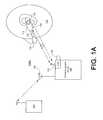
- the headset 108may further be VOX enabled and therefore may implement a VOX-PTT switch to enable the user 110 to switch between VOX-type transmission handling and PTT-type transmission handling.
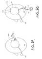
- the wireless headset 108alternatively may be implemented as a headband-type headset having a microphone assembly 218 one or two earpads 220 connected via one or more headbands 222 A or 222 B that may be positioned over and/or behind the head of the user 110 .
- FIG. 2Dillustrates an exemplary headband-type headset 200 D wherein a transmit/receive switch 224 may be positioned on the earpad 220 .
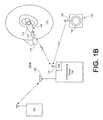
- the adapter 118may include a transmit/receive switch 902 (a button in the illustrated example) which may serve as a backup to a transmit/receive switch on the wireless headset 108 ( FIG. 1A ) or the wireless transmit/receive switch assembly 130 ( FIG. 1B ).
- the adapter 118may be affixed to the communications device 102 (e.g., a two-way radio in the illustrated example) via set screws, VELCRO®-type hook and loop fasteners, straps, adhesive, clamps and the like.
- the wireless adaptermay be operably connected to the communications device 102 via one or more conductive or optic wires so that the wireless adapter 118 may be positioned closer to the wireless headset 108 .
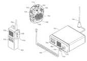
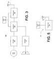
- the speakermic 908may be configured to communicate with a mobile radio 962 .
- the mobile radio 962is typically mounted in a user's vehicle, for example in a patrol car of a law enforcement officer.
- the speakermic 908is used as the microphone for the mobile radio 962 .
- the wireless connection between the speakermic 908 and the mobile radio 962permits a user to use the mobile radio outside the vehicle.
- the speakermic 908communicate with the mobile radio 962 using far field radio frequency communication permitting communications over the range of several hundred feet.
- a cord 940may be used to attach the speakermic 908 to the mobile radio 962 when the speakermic 908 is used in the vehicle.
- the wireless features of the speakermic 908also permits a mobile radio 962 to be used while the user is not within or close to the vehicle. The advantages of the mobile communications device are retained during remote operation with the speakermic 908 .
- the speakermic 908also permits a user to use a portable radio.
- the mobile communications device 962includes features typical of mobile half-duplex communications devices. Such a typical mobile radio may be installed in a vehicle such a police patrol car, a fire engine, or military vehicle. The mobile radio is used to communicate with a fixed radio at a station house or other installation. The mobile radio may also be used to communication with other mobile or portable radios. Mobile radio 962 is connected to an antenna 956 for transmitting and receiving communications to and from other communications devices such as fixed radio at a communications center or station house.
Landscapes
- Engineering & Computer Science (AREA)
- Computer Networks & Wireless Communication (AREA)
- Signal Processing (AREA)
- Transceivers (AREA)
Abstract
Description
Claims (89)
Priority Applications (1)
| Application Number | Priority Date | Filing Date | Title |
|---|---|---|---|
| US11/469,751US7818037B2 (en) | 2003-09-19 | 2006-09-01 | Techniques for wirelessly controlling push-to-talk operation of half-duplex wireless device |
Applications Claiming Priority (5)
| Application Number | Priority Date | Filing Date | Title |
|---|---|---|---|
| US50394903P | 2003-09-19 | 2003-09-19 | |
| US52777603P | 2003-12-09 | 2003-12-09 | |
| US10/828,480US7149552B2 (en) | 2003-09-19 | 2004-04-21 | Wireless headset for communications device |
| US11/264,169US7818036B2 (en) | 2003-09-19 | 2005-11-02 | Techniques for wirelessly controlling push-to-talk operation of half-duplex wireless device |
| US11/469,751US7818037B2 (en) | 2003-09-19 | 2006-09-01 | Techniques for wirelessly controlling push-to-talk operation of half-duplex wireless device |
Related Parent Applications (3)
| Application Number | Title | Priority Date | Filing Date |
|---|---|---|---|
| US10/828,480Continuation-In-PartUS7149552B2 (en) | 2003-09-19 | 2004-04-21 | Wireless headset for communications device |
| US11/246,169Continuation-In-PartUS7364232B2 (en) | 2005-04-29 | 2005-10-11 | Reclining mechanism |
| US11/264,169Continuation-In-PartUS7818036B2 (en) | 2003-09-19 | 2005-11-02 | Techniques for wirelessly controlling push-to-talk operation of half-duplex wireless device |
Publications (3)
| Publication Number | Publication Date |
|---|---|
| US20070004464A1 US20070004464A1 (en) | 2007-01-04 |
| US20090029743A9 US20090029743A9 (en) | 2009-01-29 |
| US7818037B2true US7818037B2 (en) | 2010-10-19 |
Family
ID=46326020
Family Applications (1)
| Application Number | Title | Priority Date | Filing Date |
|---|---|---|---|
| US11/469,751Expired - LifetimeUS7818037B2 (en) | 2003-09-19 | 2006-09-01 | Techniques for wirelessly controlling push-to-talk operation of half-duplex wireless device |
Country Status (1)
| Country | Link |
|---|---|
| US (1) | US7818037B2 (en) |
Cited By (47)
| Publication number | Priority date | Publication date | Assignee | Title |
|---|---|---|---|---|
| US20080181425A1 (en)* | 2007-01-19 | 2008-07-31 | Suber Edward H | Wireless speaker adapter |
| US20090209204A1 (en)* | 2008-02-18 | 2009-08-20 | Chi Mei Communication Systems, Inc. | System and method for using a mobile phone as a wireless microphone |
| US20100238018A1 (en)* | 2009-03-23 | 2010-09-23 | Chris Kelly | Mesh network enabled building safety system and method |
| US20110287719A1 (en)* | 2010-05-21 | 2011-11-24 | Motorola, Inc. | Method and system for audio routing in a vehicle mounted communication system |
| US20130072115A1 (en)* | 2011-03-22 | 2013-03-21 | Douglas Howard Dobyns | Techniques for Wireless Communication of Proximity Based Content |
| US20130297301A1 (en)* | 2012-05-03 | 2013-11-07 | Motorola Mobility, Inc. | Coupling an electronic skin tattoo to a mobile communication device |
| US20130294617A1 (en)* | 2012-05-03 | 2013-11-07 | Motorola Mobility Llc | Coupling an Electronic Skin Tattoo to a Mobile Communication Device |
| US20140113673A1 (en)* | 2012-10-22 | 2014-04-24 | Motorola Mobility Llc | Method and device with a push to talk feature |
| US8880100B2 (en) | 2011-03-23 | 2014-11-04 | Radium, Inc. | Proximity based social networking |
| US8930647B1 (en) | 2011-04-06 | 2015-01-06 | P4tents1, LLC | Multiple class memory systems |
| US9158546B1 (en) | 2011-04-06 | 2015-10-13 | P4tents1, LLC | Computer program product for fetching from a first physical memory between an execution of a plurality of threads associated with a second physical memory |
| US9164679B2 (en) | 2011-04-06 | 2015-10-20 | Patents1, Llc | System, method and computer program product for multi-thread operation involving first memory of a first memory class and second memory of a second memory class |
| US9170744B1 (en) | 2011-04-06 | 2015-10-27 | P4tents1, LLC | Computer program product for controlling a flash/DRAM/embedded DRAM-equipped system |
| US9176671B1 (en) | 2011-04-06 | 2015-11-03 | P4tents1, LLC | Fetching data between thread execution in a flash/DRAM/embedded DRAM-equipped system |
| US9210555B2 (en) | 2013-10-15 | 2015-12-08 | Twisted Pair Solutions, Inc. | Pulsed input push-to-talk wireless adapter systems and methods |
| US9249970B1 (en) | 2012-04-16 | 2016-02-02 | RRK Starlight Enterprises, LLC | Illuminated microphone stand |
| US9287040B2 (en) | 2012-07-27 | 2016-03-15 | Thoratec Corporation | Self-tuning resonant power transfer systems |
| US9398126B2 (en) | 2012-04-13 | 2016-07-19 | Motorola Solutions, Inc. | Pulsed input push-to-talk systems, methods and apparatus |
| US9400985B2 (en) | 2010-11-08 | 2016-07-26 | Radeum, Inc. | Techniques for wireless communication of proximity based content |
| US9417754B2 (en) | 2011-08-05 | 2016-08-16 | P4tents1, LLC | User interface system, method, and computer program product |
| US9583874B2 (en) | 2014-10-06 | 2017-02-28 | Thoratec Corporation | Multiaxial connector for implantable devices |
| US9592397B2 (en) | 2012-07-27 | 2017-03-14 | Thoratec Corporation | Thermal management for implantable wireless power transfer systems |
| US9621228B2 (en) | 2014-08-29 | 2017-04-11 | Freelinc Technologies | Spatially aware communications using radio frequency (RF) communications standards |
| US9628883B1 (en)* | 2015-12-02 | 2017-04-18 | Ruben Scheimberg | Wireless microphone having plural PTT buttons |
| US9680310B2 (en) | 2013-03-15 | 2017-06-13 | Thoratec Corporation | Integrated implantable TETS housing including fins and coil loops |
| US20170251289A1 (en)* | 2016-02-26 | 2017-08-31 | Cordell Eldred Ebeling | Outlet receptacle cover and mode throttling system |
| US9805863B2 (en) | 2012-07-27 | 2017-10-31 | Thoratec Corporation | Magnetic power transmission utilizing phased transmitter coil arrays and phased receiver coil arrays |
| US9825471B2 (en) | 2012-07-27 | 2017-11-21 | Thoratec Corporation | Resonant power transfer systems with protective algorithm |
| US9855437B2 (en) | 2013-11-11 | 2018-01-02 | Tc1 Llc | Hinged resonant power transfer coil |
| US10148126B2 (en) | 2015-08-31 | 2018-12-04 | Tc1 Llc | Wireless energy transfer system and wearables |
| US10164685B2 (en) | 2014-12-31 | 2018-12-25 | Freelinc Technologies Inc. | Spatially aware wireless network |
| US10177604B2 (en) | 2015-10-07 | 2019-01-08 | Tc1 Llc | Resonant power transfer systems having efficiency optimization based on receiver impedance |
| US10186760B2 (en) | 2014-09-22 | 2019-01-22 | Tc1 Llc | Antenna designs for communication between a wirelessly powered implant to an external device outside the body |
| US10251987B2 (en) | 2012-07-27 | 2019-04-09 | Tc1 Llc | Resonant power transmission coils and systems |
| US10291067B2 (en) | 2012-07-27 | 2019-05-14 | Tc1 Llc | Computer modeling for resonant power transfer systems |
| US10373756B2 (en) | 2013-03-15 | 2019-08-06 | Tc1 Llc | Malleable TETs coil with improved anatomical fit |
| US10383990B2 (en) | 2012-07-27 | 2019-08-20 | Tc1 Llc | Variable capacitor for resonant power transfer systems |
| US10525181B2 (en) | 2012-07-27 | 2020-01-07 | Tc1 Llc | Resonant power transfer system and method of estimating system state |
| US10615642B2 (en) | 2013-11-11 | 2020-04-07 | Tc1 Llc | Resonant power transfer systems with communications |
| US10610692B2 (en) | 2014-03-06 | 2020-04-07 | Tc1 Llc | Electrical connectors for implantable devices |
| US10695476B2 (en) | 2013-11-11 | 2020-06-30 | Tc1 Llc | Resonant power transfer systems with communications |
| US10770923B2 (en) | 2018-01-04 | 2020-09-08 | Tc1 Llc | Systems and methods for elastic wireless power transmission devices |
| US10898292B2 (en) | 2016-09-21 | 2021-01-26 | Tc1 Llc | Systems and methods for locating implanted wireless power transmission devices |
| US10924847B2 (en) | 2019-01-14 | 2021-02-16 | Yamaha Guitar Group, Inc. | Microphone that functions as either a digital wireless microphone or a wired passive microphone |
| US11026013B2 (en) | 2019-10-02 | 2021-06-01 | Mobilus Labs Limited | Bone conduction communication system and method of operation |
| US11197990B2 (en) | 2017-01-18 | 2021-12-14 | Tc1 Llc | Systems and methods for transcutaneous power transfer using microneedles |
| US20240187781A1 (en)* | 2022-12-01 | 2024-06-06 | Falcom A/S | Headset |
Families Citing this family (56)
| Publication number | Priority date | Publication date | Assignee | Title |
|---|---|---|---|---|
| US7366295B2 (en)* | 2003-08-14 | 2008-04-29 | John David Patton | Telephone signal generator and methods and devices using the same |
| US7818036B2 (en)* | 2003-09-19 | 2010-10-19 | Radeum, Inc. | Techniques for wirelessly controlling push-to-talk operation of half-duplex wireless device |
| US8023984B2 (en)* | 2003-10-06 | 2011-09-20 | Research In Motion Limited | System and method of controlling transmit power for mobile wireless devices with multi-mode operation of antenna |
| US8095081B2 (en)* | 2004-04-29 | 2012-01-10 | Sony Ericsson Mobile Communications Ab | Device and method for hands-free push-to-talk functionality |
| CA2577372A1 (en)* | 2004-08-18 | 2006-03-02 | Micro Ear Technology, Inc. D/B/A Micro-Tech | Method and apparatus for wireless communication using an inductive interface |
| US7813762B2 (en)* | 2004-08-18 | 2010-10-12 | Micro Ear Technology, Inc. | Wireless communications adapter for a hearing assistance device |
| US7599719B2 (en)* | 2005-02-14 | 2009-10-06 | John D. Patton | Telephone and telephone accessory signal generator and methods and devices using the same |
| US9774961B2 (en) | 2005-06-05 | 2017-09-26 | Starkey Laboratories, Inc. | Hearing assistance device ear-to-ear communication using an intermediate device |
| US8041066B2 (en) | 2007-01-03 | 2011-10-18 | Starkey Laboratories, Inc. | Wireless system for hearing communication devices providing wireless stereo reception modes |
| TWM280051U (en)* | 2005-07-08 | 2005-11-01 | Pchome Online Inc | Internet protocol phone having female stereo connector |
| US7627289B2 (en)* | 2005-12-23 | 2009-12-01 | Plantronics, Inc. | Wireless stereo headset |
| US8027638B2 (en) | 2006-03-29 | 2011-09-27 | Micro Ear Technology, Inc. | Wireless communication system using custom earmold |
| US20070281614A1 (en)* | 2006-06-01 | 2007-12-06 | Motorola, Inc. | Method and apparatus for dual mode communications |
| US8208642B2 (en) | 2006-07-10 | 2012-06-26 | Starkey Laboratories, Inc. | Method and apparatus for a binaural hearing assistance system using monaural audio signals |
| US20080112512A1 (en)* | 2006-11-15 | 2008-05-15 | Qualcomm Incorporated | Transmitted reference signaling scheme |
| US20080192951A1 (en)* | 2007-02-08 | 2008-08-14 | Edward Moura | Spectator broadcast system with an ear mounted receiver |
| US8271037B2 (en)* | 2007-02-28 | 2012-09-18 | Motorola Solutions, Inc. | Method and system for automatic audio accessory use position detection and audio adjustment |
| US8635654B2 (en)* | 2007-04-30 | 2014-01-21 | Thales Avionics, Inc. | Wireless audio distribution system and method for an in-flight entertainment system |
| KR100827613B1 (en)* | 2007-05-04 | 2008-05-07 | 삼성전자주식회사 | Microphone control device and method of portable terminal |
| US20090017881A1 (en)* | 2007-07-10 | 2009-01-15 | David Madrigal | Storage and activation of mobile phone components |
| WO2009012491A2 (en)* | 2007-07-19 | 2009-01-22 | Personics Holdings Inc. | Device and method for remote acoustic porting and magnetic acoustic connection |
| WO2009021220A1 (en)* | 2007-08-08 | 2009-02-12 | Radeum, Inc. | Near field communications system having enhanced security |
| WO2009042977A1 (en)* | 2007-09-26 | 2009-04-02 | Radeum, Inc. Dba Freelinc | System and method for near field communications having local security |
| KR101426707B1 (en)* | 2007-11-26 | 2014-08-05 | 삼성전자주식회사 | How to show your wireless headset and its battery status |
| US20090203318A1 (en)* | 2008-02-11 | 2009-08-13 | Haan Ido De | Headset |
| US8078120B2 (en)* | 2008-02-11 | 2011-12-13 | Cobra Electronics Corporation | Citizens band radio with wireless cellular telephone connectivity |
| WO2009102663A1 (en)* | 2008-02-11 | 2009-08-20 | Cobra Electronics Corporation | Marine communication device with wireless cellular telephone connectivity |
| CA2720785C (en) | 2008-04-07 | 2015-05-12 | Koss Corporation | Wireless earphone that transitions between wireless networks |
| DE102008037717B4 (en)* | 2008-06-04 | 2019-05-23 | Huf Hülsbeck & Fürst Gmbh & Co. Kg | Mobile identification transmitter of a security system |
| US8883872B2 (en) | 2009-07-06 | 2014-11-11 | Basf Se | Polymer-bound bisacylphosphine oxides |
| US9198800B2 (en)* | 2009-10-30 | 2015-12-01 | Etymotic Research, Inc. | Electronic earplug for providing communication and protection |
| US9420385B2 (en) | 2009-12-21 | 2016-08-16 | Starkey Laboratories, Inc. | Low power intermittent messaging for hearing assistance devices |
| US8503708B2 (en) | 2010-04-08 | 2013-08-06 | Starkey Laboratories, Inc. | Hearing assistance device with programmable direct audio input port |
| US20120046009A1 (en)* | 2010-08-23 | 2012-02-23 | Sony Ericsson Mobile Communications Ab | Personal Emergency System for a Mobile Communication Device |
| US9397726B2 (en) | 2010-08-23 | 2016-07-19 | Radeum, Inc. | System and method for communicating between near field communication devices within a target region using near field communication |
| SE535539C2 (en)* | 2010-11-23 | 2012-09-18 | Hylte Lantmaen Ekonomisk Foerening | Communication device comprising a mobile phone and a hunting radio |
| US8380128B2 (en)* | 2010-11-30 | 2013-02-19 | Motorola Solutions, Inc. | User interface for a communication system |
| US9054781B2 (en)* | 2011-02-23 | 2015-06-09 | Harris Corporation | Land mobile radio and adapter for use with standard mobile phone headset |
| US20130328667A1 (en)* | 2012-06-10 | 2013-12-12 | Apple Inc. | Remote interaction with siri |
| US9443515B1 (en) | 2012-09-05 | 2016-09-13 | Paul G. Boyce | Personality designer system for a detachably attachable remote audio object |
| US9615219B2 (en)* | 2013-05-29 | 2017-04-04 | Motorola Solutions, Inc. | Method and apparatus for operating a portable radio communication device in a dual-watch mode |
| US9973905B2 (en) | 2013-08-09 | 2018-05-15 | Savox International S.A. | Communication apparatus, a communication arrangement and a communication method |
| US11307282B2 (en)* | 2013-10-25 | 2022-04-19 | Ultrahaptics IP Two Limited | Determining positional information for an object in space |
| US9319089B1 (en)* | 2014-02-24 | 2016-04-19 | The United States of America as requested by the Secretary of the Air Force | Apparatus for interfacing auxiliary devices with radio communication hardware |
| US10110984B2 (en)* | 2014-04-21 | 2018-10-23 | Apple Inc. | Wireless earphone |
| US10003379B2 (en) | 2014-05-06 | 2018-06-19 | Starkey Laboratories, Inc. | Wireless communication with probing bandwidth |
| US9537321B2 (en)* | 2015-02-25 | 2017-01-03 | Motorola Solutions, Inc. | Method and apparatus for power transfer for a portable electronic device |
| US10135411B2 (en)* | 2016-05-19 | 2018-11-20 | Michael D. Dieringer | Patrol vehicle communications system for users of both mobile and portable radios |
| DE102017111191A1 (en)* | 2017-05-23 | 2018-11-29 | Sennheiser Electronic Gmbh & Co. Kg | Wireless audio transmission system with at least one microphone hand transmitter and / or a bodypack |
| US20190181685A1 (en)* | 2017-12-08 | 2019-06-13 | Atmosic Technologies Inc. | Method and apparatus for wireless transmission and reception of power |
| US10412680B1 (en) | 2018-03-09 | 2019-09-10 | Atmosic Technologies Inc. | Method and apparatus for controlling power dissipation in a wireless receiver |
| US11178616B2 (en) | 2018-09-04 | 2021-11-16 | Atmosic Technologies Inc. | Staged wireless device wake-up |
| US11297409B2 (en) | 2019-04-18 | 2022-04-05 | Safariland, Llc | Remote speaker microphone unit for use with headset |
| US11785428B2 (en)* | 2019-08-23 | 2023-10-10 | 3M Innovative Properties Company | Mobile radio |
| US11996878B1 (en) | 2020-03-06 | 2024-05-28 | United States Of America As Represented By The Secretary Of The Air Force | Custom audio signal enhancement adapter |
| US12401972B2 (en)* | 2021-10-11 | 2025-08-26 | Bitwave Pte Ltd | Intelligent speech control for two way radio |
Citations (61)
| Publication number | Priority date | Publication date | Assignee | Title |
|---|---|---|---|---|
| US4132861A (en) | 1977-07-27 | 1979-01-02 | Gentex Corporation | Headset having double-coil earphone |
| US4334315A (en) | 1979-05-04 | 1982-06-08 | Gen Engineering, Ltd. | Wireless transmitting and receiving systems including ear microphones |
| US5101504A (en) | 1989-06-13 | 1992-03-31 | Lenz Vernon C | Shoulder activated headset |
| US5118309A (en) | 1991-04-01 | 1992-06-02 | Motorola, Inc. | Minimum wire interface for multiple accessories |
| US5263181A (en) | 1990-10-18 | 1993-11-16 | Motorola, Inc. | Remote transmitter for triggering a voice-operated radio |
| US5265264A (en) | 1991-12-23 | 1993-11-23 | Motorola, Inc. | Convertible half-to-full duplex radio operation selected by battery |
| US5276916A (en) | 1991-10-08 | 1994-01-04 | Motorola, Inc. | Communication device having a speaker and microphone |
| US5448620A (en) | 1992-07-02 | 1995-09-05 | Motorola, Inc. | Volume control for a dual mode communications device |
| US5479474A (en) | 1992-10-05 | 1995-12-26 | Motorola, Inc. | Communication system having a remote unit, a fixed unit and a half-duplex communication channel |
| US5568516A (en) | 1993-07-02 | 1996-10-22 | Phonic Ear Incorporated | Very low power cordless headset system |
| US5659156A (en) | 1995-02-03 | 1997-08-19 | Jabra Corporation | Earmolds for two-way communications devices |
| EP0798474A1 (en) | 1996-03-26 | 1997-10-01 | Paul Hellermann GmbH | Connecting assembly |
| US5678207A (en) | 1995-04-28 | 1997-10-14 | Motorola, Inc. | Radio/Microphone battery charging assembly |
| US5748707A (en) | 1994-10-07 | 1998-05-05 | Sanserino; Jon J | Speakerphone with remote microphone having speaker cut-off for half-duplex operation |
| JPH10150694A (en) | 1996-11-18 | 1998-06-02 | Hitachi Denshi Ltd | Microphone circuit |
| US5771438A (en) | 1995-05-18 | 1998-06-23 | Aura Communications, Inc. | Short-range magnetic communication system |
| US5790681A (en) | 1996-06-28 | 1998-08-04 | Kitek Oy Ab Insinooritoimisto | Fixing assembly for a helmet headset |
| US5912925A (en) | 1995-05-18 | 1999-06-15 | Aura Communications, Inc. | Diversity circuit for magnetic communication system |
| US5926532A (en) | 1995-10-26 | 1999-07-20 | Peck/Pellssier | Integrated wireless communication system |
| US5969698A (en) | 1993-11-29 | 1999-10-19 | Motorola, Inc. | Manually controllable cursor and control panel in a virtual image |
| US5982764A (en) | 1995-05-18 | 1999-11-09 | Aura Communications, Inc. | Time-multiplexed short-range magnetic communications |
| US5987146A (en) | 1997-04-03 | 1999-11-16 | Resound Corporation | Ear canal microphone |
| US6104816A (en) | 1998-08-31 | 2000-08-15 | The United States Of America As Represented By The Secretary Of The Navy | High noise communication system |
| US6121881A (en) | 1994-09-02 | 2000-09-19 | Safety Tech Industries, Inc. | Protective mask communication devices and systems for use in hazardous environments |
| US6230029B1 (en) | 1998-01-07 | 2001-05-08 | Advanced Mobile Solutions, Inc. | Modular wireless headset system |
| US6298249B1 (en) | 1998-10-08 | 2001-10-02 | Mine Safety Appliances Company | Radio apparatus head-protective helmet |
| US6304559B1 (en) | 1998-05-15 | 2001-10-16 | Northrop Grumman Corporation | Wireless communications protocol |
| US6311052B1 (en) | 1999-04-13 | 2001-10-30 | Golden West Communications, Inc. | PTT radio system |
| US6351653B1 (en) | 2000-06-15 | 2002-02-26 | Motorola, Inc. | Cellular telephone with simultaneous radio and cellular communications |
| US20020057746A1 (en) | 2000-11-10 | 2002-05-16 | Motorola Inc. | Apparatus for receiving and recovering frequency shift keyed symbols |
| US20020068600A1 (en) | 2000-06-21 | 2002-06-06 | Hiroyuki Chihara | Mobile video telephone system |
| US6424820B1 (en) | 1999-04-02 | 2002-07-23 | Interval Research Corporation | Inductively coupled wireless system and method |
| US20020107053A1 (en) | 2001-02-05 | 2002-08-08 | Petez Jose A. | PTT speaker/mike assembly |
| US20020132585A1 (en)* | 2001-03-16 | 2002-09-19 | Aura Communications, Inc. | Techniques for inductive communication systems |
| US6459371B1 (en) | 1997-10-20 | 2002-10-01 | Steven Derek Pike | Locating device |
| US20020160722A1 (en) | 2001-03-16 | 2002-10-31 | Aura Communications, Inc. | Wireless communication over a transducer device |
| US6522894B1 (en) | 1999-07-27 | 2003-02-18 | Ericsson Inc. | Simplified speaker mode selection for wireless communications device |
| US20030059078A1 (en) | 2001-06-21 | 2003-03-27 | Downs Edward F. | Directional sensors for head-mounted contact microphones |
| US20030092399A1 (en) | 1999-12-16 | 2003-05-15 | John Davies | Radio system with cordless remote ptt module |
| US20030100274A1 (en) | 2001-11-28 | 2003-05-29 | Sendo International Limited | Wireless Headset-Based Communication |
| US20030120487A1 (en) | 2001-12-20 | 2003-06-26 | Hitachi, Ltd. | Dynamic adjustment of noise separation in data handling, particularly voice activation |
| US20030207694A1 (en) | 2002-05-06 | 2003-11-06 | Legare David J. | Apparatus and method for a multi-channel, multi-user wireless intercom |
| US20030211871A1 (en)* | 2002-05-09 | 2003-11-13 | Shary Nassimi | Wireless headset |
| US20030224825A1 (en) | 2002-06-03 | 2003-12-04 | Cox Gregory W. | Method and apparatus for interactive communication between half-duplex and full-duplex systems |
| US20030224838A1 (en) | 2001-07-18 | 2003-12-04 | Greg Skillicorn | Mask communication system |
| US6671379B2 (en) | 2001-03-30 | 2003-12-30 | Think-A-Move, Ltd. | Ear microphone apparatus and method |
| US6681022B1 (en) | 1998-07-22 | 2004-01-20 | Gn Resound North Amerca Corporation | Two-way communication earpiece |
| US20040022395A1 (en) | 2002-08-01 | 2004-02-05 | Jabra Corporation | Dual mode transmission device |
| US6688421B2 (en) | 2002-04-18 | 2004-02-10 | Jabra Corporation | Earmold for improved retention of coupled device |
| US6745014B1 (en)* | 1999-10-28 | 2004-06-01 | The United States Of America As Represented By The Administrator Of The National Aeronautics And Space Administration | Communications interface for wireless communications headset |
| US6795718B2 (en) | 2002-02-15 | 2004-09-21 | Youngbo Engineering, Inc. | Headset communication device |
| US20040198436A1 (en) | 2002-04-09 | 2004-10-07 | Alden Richard P. | Personal portable integrator for music player and mobile phone |
| US20040198425A1 (en)* | 2002-10-01 | 2004-10-07 | Mellone Charles M. | Establishing half-duplex audio link as battery saving means |
| US6819762B2 (en) | 2001-03-16 | 2004-11-16 | Aura Communications, Inc. | In-the-ear headset |
| US6823195B1 (en) | 2000-06-30 | 2004-11-23 | Peter V. Boesen | Ultra short range communication with sensing device and method |
| US20050057359A1 (en)* | 2003-08-12 | 2005-03-17 | Conor Coffey | Transmitter unit and control unit |
| US6950627B2 (en) | 2002-03-27 | 2005-09-27 | Microelectronics Research | Method and apparatus for providing a wireless aircraft interphone system |
| US7010332B1 (en) | 2000-02-21 | 2006-03-07 | Telefonaktiebolaget Lm Ericsson(Publ) | Wireless headset with automatic power control |
| US20060073787A1 (en) | 2003-09-19 | 2006-04-06 | John Lair | Wireless headset for communications device |
| US7035608B2 (en) | 2001-03-16 | 2006-04-25 | Aura Communications Technology, Inc. | Methods and apparatus for tuning in an inductive system |
| US7149552B2 (en) | 2003-09-19 | 2006-12-12 | Radeum, Inc. | Wireless headset for communications device |
Family Cites Families (2)
| Publication number | Priority date | Publication date | Assignee | Title |
|---|---|---|---|---|
| IT1251497B (en)* | 1991-09-18 | 1995-05-15 | Mivett Nuovi Lab Di Pavani& C | USE OF 1,2 DIPALMITOIL-L-ALFA-FOSFATIDIL-N, N-DIMETYLETHANOLAMINE, IN DERMATOLOGICAL COMPOSITIONS |
| EP0646981B1 (en)* | 1993-10-04 | 1999-04-28 | Matsushita Electric Industrial Co., Ltd. | Stripline filter and dual mode resonator |
- 2006
- 2006-09-01USUS11/469,751patent/US7818037B2/ennot_activeExpired - Lifetime
Patent Citations (66)
| Publication number | Priority date | Publication date | Assignee | Title |
|---|---|---|---|---|
| US4132861A (en) | 1977-07-27 | 1979-01-02 | Gentex Corporation | Headset having double-coil earphone |
| US4334315A (en) | 1979-05-04 | 1982-06-08 | Gen Engineering, Ltd. | Wireless transmitting and receiving systems including ear microphones |
| US5101504A (en) | 1989-06-13 | 1992-03-31 | Lenz Vernon C | Shoulder activated headset |
| US5263181A (en) | 1990-10-18 | 1993-11-16 | Motorola, Inc. | Remote transmitter for triggering a voice-operated radio |
| US5118309A (en) | 1991-04-01 | 1992-06-02 | Motorola, Inc. | Minimum wire interface for multiple accessories |
| US5276916A (en) | 1991-10-08 | 1994-01-04 | Motorola, Inc. | Communication device having a speaker and microphone |
| US5265264A (en) | 1991-12-23 | 1993-11-23 | Motorola, Inc. | Convertible half-to-full duplex radio operation selected by battery |
| US5448620A (en) | 1992-07-02 | 1995-09-05 | Motorola, Inc. | Volume control for a dual mode communications device |
| US5479474A (en) | 1992-10-05 | 1995-12-26 | Motorola, Inc. | Communication system having a remote unit, a fixed unit and a half-duplex communication channel |
| US5568516A (en) | 1993-07-02 | 1996-10-22 | Phonic Ear Incorporated | Very low power cordless headset system |
| US5969698A (en) | 1993-11-29 | 1999-10-19 | Motorola, Inc. | Manually controllable cursor and control panel in a virtual image |
| US6121881A (en) | 1994-09-02 | 2000-09-19 | Safety Tech Industries, Inc. | Protective mask communication devices and systems for use in hazardous environments |
| US5748707A (en) | 1994-10-07 | 1998-05-05 | Sanserino; Jon J | Speakerphone with remote microphone having speaker cut-off for half-duplex operation |
| US5659156A (en) | 1995-02-03 | 1997-08-19 | Jabra Corporation | Earmolds for two-way communications devices |
| US5678207A (en) | 1995-04-28 | 1997-10-14 | Motorola, Inc. | Radio/Microphone battery charging assembly |
| US5982764A (en) | 1995-05-18 | 1999-11-09 | Aura Communications, Inc. | Time-multiplexed short-range magnetic communications |
| US20050164636A1 (en) | 1995-05-18 | 2005-07-28 | Aura Communications Technology, Inc. | Inductive communication system and method |
| US5912925A (en) | 1995-05-18 | 1999-06-15 | Aura Communications, Inc. | Diversity circuit for magnetic communication system |
| US6459882B1 (en) | 1995-05-18 | 2002-10-01 | Aura Communications, Inc. | Inductive communication system and method |
| US5771438A (en) | 1995-05-18 | 1998-06-23 | Aura Communications, Inc. | Short-range magnetic communication system |
| US5926532A (en) | 1995-10-26 | 1999-07-20 | Peck/Pellssier | Integrated wireless communication system |
| EP0798474A1 (en) | 1996-03-26 | 1997-10-01 | Paul Hellermann GmbH | Connecting assembly |
| US5790681A (en) | 1996-06-28 | 1998-08-04 | Kitek Oy Ab Insinooritoimisto | Fixing assembly for a helmet headset |
| JPH10150694A (en) | 1996-11-18 | 1998-06-02 | Hitachi Denshi Ltd | Microphone circuit |
| US5987146A (en) | 1997-04-03 | 1999-11-16 | Resound Corporation | Ear canal microphone |
| US6459371B1 (en) | 1997-10-20 | 2002-10-01 | Steven Derek Pike | Locating device |
| US6230029B1 (en) | 1998-01-07 | 2001-05-08 | Advanced Mobile Solutions, Inc. | Modular wireless headset system |
| US6304559B1 (en) | 1998-05-15 | 2001-10-16 | Northrop Grumman Corporation | Wireless communications protocol |
| US6681022B1 (en) | 1998-07-22 | 2004-01-20 | Gn Resound North Amerca Corporation | Two-way communication earpiece |
| US6104816A (en) | 1998-08-31 | 2000-08-15 | The United States Of America As Represented By The Secretary Of The Navy | High noise communication system |
| US6298249B1 (en) | 1998-10-08 | 2001-10-02 | Mine Safety Appliances Company | Radio apparatus head-protective helmet |
| US6424820B1 (en) | 1999-04-02 | 2002-07-23 | Interval Research Corporation | Inductively coupled wireless system and method |
| US6311052B1 (en) | 1999-04-13 | 2001-10-30 | Golden West Communications, Inc. | PTT radio system |
| US6522894B1 (en) | 1999-07-27 | 2003-02-18 | Ericsson Inc. | Simplified speaker mode selection for wireless communications device |
| US6745014B1 (en)* | 1999-10-28 | 2004-06-01 | The United States Of America As Represented By The Administrator Of The National Aeronautics And Space Administration | Communications interface for wireless communications headset |
| US7058384B2 (en) | 1999-12-16 | 2006-06-06 | Davies Industrial Communications Limited | Radio system with universal communication interface |
| US20030092399A1 (en) | 1999-12-16 | 2003-05-15 | John Davies | Radio system with cordless remote ptt module |
| US7010332B1 (en) | 2000-02-21 | 2006-03-07 | Telefonaktiebolaget Lm Ericsson(Publ) | Wireless headset with automatic power control |
| US6351653B1 (en) | 2000-06-15 | 2002-02-26 | Motorola, Inc. | Cellular telephone with simultaneous radio and cellular communications |
| US20020068600A1 (en) | 2000-06-21 | 2002-06-06 | Hiroyuki Chihara | Mobile video telephone system |
| US6823195B1 (en) | 2000-06-30 | 2004-11-23 | Peter V. Boesen | Ultra short range communication with sensing device and method |
| US20020057746A1 (en) | 2000-11-10 | 2002-05-16 | Motorola Inc. | Apparatus for receiving and recovering frequency shift keyed symbols |
| US20020107053A1 (en) | 2001-02-05 | 2002-08-08 | Petez Jose A. | PTT speaker/mike assembly |
| US6819762B2 (en) | 2001-03-16 | 2004-11-16 | Aura Communications, Inc. | In-the-ear headset |
| US7035608B2 (en) | 2001-03-16 | 2006-04-25 | Aura Communications Technology, Inc. | Methods and apparatus for tuning in an inductive system |
| US20020160722A1 (en) | 2001-03-16 | 2002-10-31 | Aura Communications, Inc. | Wireless communication over a transducer device |
| US20020132585A1 (en)* | 2001-03-16 | 2002-09-19 | Aura Communications, Inc. | Techniques for inductive communication systems |
| US20060073825A1 (en) | 2001-03-16 | 2006-04-06 | Vincent Palermo | Techniques for inductive communication systems |
| US20070082611A1 (en) | 2001-03-16 | 2007-04-12 | Terranova Domenic F | Wireless communication over a transducer device |
| US6671379B2 (en) | 2001-03-30 | 2003-12-30 | Think-A-Move, Ltd. | Ear microphone apparatus and method |
| US20030059078A1 (en) | 2001-06-21 | 2003-03-27 | Downs Edward F. | Directional sensors for head-mounted contact microphones |
| US20030224838A1 (en) | 2001-07-18 | 2003-12-04 | Greg Skillicorn | Mask communication system |
| US20030100274A1 (en) | 2001-11-28 | 2003-05-29 | Sendo International Limited | Wireless Headset-Based Communication |
| US20030120487A1 (en) | 2001-12-20 | 2003-06-26 | Hitachi, Ltd. | Dynamic adjustment of noise separation in data handling, particularly voice activation |
| US6795718B2 (en) | 2002-02-15 | 2004-09-21 | Youngbo Engineering, Inc. | Headset communication device |
| US6950627B2 (en) | 2002-03-27 | 2005-09-27 | Microelectronics Research | Method and apparatus for providing a wireless aircraft interphone system |
| US20040198436A1 (en) | 2002-04-09 | 2004-10-07 | Alden Richard P. | Personal portable integrator for music player and mobile phone |
| US6688421B2 (en) | 2002-04-18 | 2004-02-10 | Jabra Corporation | Earmold for improved retention of coupled device |
| US20030207694A1 (en) | 2002-05-06 | 2003-11-06 | Legare David J. | Apparatus and method for a multi-channel, multi-user wireless intercom |
| US20030211871A1 (en)* | 2002-05-09 | 2003-11-13 | Shary Nassimi | Wireless headset |
| US20030224825A1 (en) | 2002-06-03 | 2003-12-04 | Cox Gregory W. | Method and apparatus for interactive communication between half-duplex and full-duplex systems |
| US20040022395A1 (en) | 2002-08-01 | 2004-02-05 | Jabra Corporation | Dual mode transmission device |
| US20040198425A1 (en)* | 2002-10-01 | 2004-10-07 | Mellone Charles M. | Establishing half-duplex audio link as battery saving means |
| US20050057359A1 (en)* | 2003-08-12 | 2005-03-17 | Conor Coffey | Transmitter unit and control unit |
| US20060073787A1 (en) | 2003-09-19 | 2006-04-06 | John Lair | Wireless headset for communications device |
| US7149552B2 (en) | 2003-09-19 | 2006-12-12 | Radeum, Inc. | Wireless headset for communications device |
Non-Patent Citations (13)
| Title |
|---|
| Earmark, Base Stations: CON-KIT Base Station, printed Mar. 16, 2004, 2 pages {http://www.earmark.com/products/conbase.html}. |
| Eartec, Heavy Duty Headsets, printed Mar. 24, 2004, 3 pages, {http://www.eartech.com/ultra.html}. |
| Eartec, Specialty Headset Communication Systems, Brochure {Date Unknown}. |
| Eartec, Voice Activated or push to talk wireless, ProTalk UHF, printed Mar. 24, 2004, 3 pages, {http://www.eartec.com/protalk.html}. |
| Jabra, Freespeak 250, The cordless headset for bluetooth mobile phones, 2004, 2 pages. |
| Jtech Australia Pty Ltd., 2-Way Radios, printed Mar. 16, 2004, 2 pages {http://www.jtech.com.au/2way.asp?p=products}. |
| Logitech, Mobile Phone Headsets, printed Apr. 6, 2004 {http://www.logitech.com/index.cfm/products/productlist/US/EN,crid=1627,ad=lgpr-mobile}. |
| Logitech, Mobile Phone Headsets, printed Apr. 6, 2004 {http://www.logitech.com/index.cfm/products/productlist/US/EN,crid=1627,ad=lgpr—mobile}. |
| Motorola Intelligence Everywhere, Enhance your MTH650 Tetra handportable terminal with a wide range of accessories, May 14, 2003, 6 pages. |
| Motorola Intelligence Everywhere, MTH500 Motorola Tetra Portable Radio, 2001, 2 pages. |
| The Bluetooth Weblog, Frog Design/Motorola Offspring Wearables Concept, printed Aug. 4, 2003, 3 pages, {http://bluetooth.weblogs.com/discuss/msgReader$532?mode=topic}. |
| UHF Wireless Intercom, System 800, Home Electronics, Inc., 2 pages {Date Unknown}. |
| Uniden WHAM Accessory Wireless Microphone Owner's Manual. |
Cited By (142)
| Publication number | Priority date | Publication date | Assignee | Title |
|---|---|---|---|---|
| US20080181425A1 (en)* | 2007-01-19 | 2008-07-31 | Suber Edward H | Wireless speaker adapter |
| US8000479B2 (en)* | 2007-01-19 | 2011-08-16 | Edward H. Suber, III | Wireless speaker adapter |
| US20090209204A1 (en)* | 2008-02-18 | 2009-08-20 | Chi Mei Communication Systems, Inc. | System and method for using a mobile phone as a wireless microphone |
| US8010088B2 (en)* | 2008-02-18 | 2011-08-30 | Chi Mei Communication Systems, Inc. | System and method for using a mobile phone as a wireless microphone |
| US20100238018A1 (en)* | 2009-03-23 | 2010-09-23 | Chris Kelly | Mesh network enabled building safety system and method |
| US10991232B2 (en) | 2009-03-23 | 2021-04-27 | Chris Kelly | Mesh network enabled building safety system and method |
| US10600315B2 (en)* | 2009-03-23 | 2020-03-24 | Chris Kelly | Mesh network enabled building safety system and method |
| US20110287719A1 (en)* | 2010-05-21 | 2011-11-24 | Motorola, Inc. | Method and system for audio routing in a vehicle mounted communication system |
| US8509693B2 (en)* | 2010-05-21 | 2013-08-13 | Motorola Solutions, Inc. | Method and system for audio routing in a vehicle mounted communication system |
| US9400985B2 (en) | 2010-11-08 | 2016-07-26 | Radeum, Inc. | Techniques for wireless communication of proximity based content |
| US10117050B2 (en) | 2010-11-08 | 2018-10-30 | Freelinc Technologies Inc. | Techniques for wireless communication of proximity based content |
| US20150044968A1 (en)* | 2011-03-22 | 2015-02-12 | Radeum, Inc. | Systems and method for close proximity communication |
| US9455771B2 (en)* | 2011-03-22 | 2016-09-27 | Freelinc Technologies Inc. | System and method for close proximity communication |
| US20130072115A1 (en)* | 2011-03-22 | 2013-03-21 | Douglas Howard Dobyns | Techniques for Wireless Communication of Proximity Based Content |
| US8929809B2 (en)* | 2011-03-22 | 2015-01-06 | Radeum, Inc. | Techniques for wireless communication of proximity based content |
| US20200044696A1 (en)* | 2011-03-22 | 2020-02-06 | Freelinc Holdings, Llc | System and method for close proximity communication |
| US10103786B2 (en) | 2011-03-22 | 2018-10-16 | Freelinc Technologies Inc. | System and method for close proximity communication |
| US20190229772A1 (en)* | 2011-03-22 | 2019-07-25 | Freelinc Technologies Inc. | System and method for close proximity communication |
| US8880100B2 (en) | 2011-03-23 | 2014-11-04 | Radium, Inc. | Proximity based social networking |
| US9560505B2 (en) | 2011-03-23 | 2017-01-31 | Freelinc Technologies Inc. | Proximity based social networking |
| US9164679B2 (en) | 2011-04-06 | 2015-10-20 | Patents1, Llc | System, method and computer program product for multi-thread operation involving first memory of a first memory class and second memory of a second memory class |
| US9195395B1 (en) | 2011-04-06 | 2015-11-24 | P4tents1, LLC | Flash/DRAM/embedded DRAM-equipped system and method |
| US9189442B1 (en) | 2011-04-06 | 2015-11-17 | P4tents1, LLC | Fetching data between thread execution in a flash/DRAM/embedded DRAM-equipped system |
| US9223507B1 (en) | 2011-04-06 | 2015-12-29 | P4tents1, LLC | System, method and computer program product for fetching data between an execution of a plurality of threads |
| US9182914B1 (en) | 2011-04-06 | 2015-11-10 | P4tents1, LLC | System, method and computer program product for multi-thread operation involving first memory of a first memory class and second memory of a second memory class |
| US9176671B1 (en) | 2011-04-06 | 2015-11-03 | P4tents1, LLC | Fetching data between thread execution in a flash/DRAM/embedded DRAM-equipped system |
| US9170744B1 (en) | 2011-04-06 | 2015-10-27 | P4tents1, LLC | Computer program product for controlling a flash/DRAM/embedded DRAM-equipped system |
| US9158546B1 (en) | 2011-04-06 | 2015-10-13 | P4tents1, LLC | Computer program product for fetching from a first physical memory between an execution of a plurality of threads associated with a second physical memory |
| US8930647B1 (en) | 2011-04-06 | 2015-01-06 | P4tents1, LLC | Multiple class memory systems |
| US10656757B1 (en) | 2011-08-05 | 2020-05-19 | P4tents1, LLC | Gesture-equipped touch screen system, method, and computer program product |
| US10649571B1 (en) | 2011-08-05 | 2020-05-12 | P4tents1, LLC | Devices, methods, and graphical user interfaces for manipulating user interface objects with visual and/or haptic feedback |
| US10540039B1 (en) | 2011-08-05 | 2020-01-21 | P4tents1, LLC | Devices and methods for navigating between user interface |
| US10936114B1 (en) | 2011-08-05 | 2021-03-02 | P4tents1, LLC | Gesture-equipped touch screen system, method, and computer program product |
| US10838542B1 (en) | 2011-08-05 | 2020-11-17 | P4tents1, LLC | Gesture-equipped touch screen system, method, and computer program product |
| US10788931B1 (en) | 2011-08-05 | 2020-09-29 | P4tents1, LLC | Devices, methods, and graphical user interfaces for manipulating user interface objects with visual and/or haptic feedback |
| US10782819B1 (en) | 2011-08-05 | 2020-09-22 | P4tents1, LLC | Gesture-equipped touch screen system, method, and computer program product |
| US10725581B1 (en) | 2011-08-05 | 2020-07-28 | P4tents1, LLC | Devices, methods and graphical user interfaces for manipulating user interface objects with visual and/or haptic feedback |
| US10671212B1 (en) | 2011-08-05 | 2020-06-02 | P4tents1, LLC | Gesture-equipped touch screen system, method, and computer program product |
| US10671213B1 (en) | 2011-08-05 | 2020-06-02 | P4tents1, LLC | Devices, methods, and graphical user interfaces for manipulating user interface objects with visual and/or haptic feedback |
| US10664097B1 (en) | 2011-08-05 | 2020-05-26 | P4tents1, LLC | Devices, methods, and graphical user interfaces for manipulating user interface objects with visual and/or haptic feedback |
| US10656754B1 (en) | 2011-08-05 | 2020-05-19 | P4tents1, LLC | Devices and methods for navigating between user interfaces |
| US10656759B1 (en) | 2011-08-05 | 2020-05-19 | P4tents1, LLC | Devices, methods, and graphical user interfaces for manipulating user interface objects with visual and/or haptic feedback |
| US10534474B1 (en) | 2011-08-05 | 2020-01-14 | P4tents1, LLC | Gesture-equipped touch screen system, method, and computer program product |
| US10656756B1 (en) | 2011-08-05 | 2020-05-19 | P4tents1, LLC | Gesture-equipped touch screen system, method, and computer program product |
| US10656758B1 (en) | 2011-08-05 | 2020-05-19 | P4tents1, LLC | Gesture-equipped touch screen system, method, and computer program product |
| US10031607B1 (en) | 2011-08-05 | 2018-07-24 | P4tents1, LLC | System, method, and computer program product for a multi-pressure selection touch screen |
| US10656755B1 (en) | 2011-08-05 | 2020-05-19 | P4tents1, LLC | Gesture-equipped touch screen system, method, and computer program product |
| US10656753B1 (en) | 2011-08-05 | 2020-05-19 | P4tents1, LLC | Gesture-equipped touch screen system, method, and computer program product |
| US10996787B1 (en) | 2011-08-05 | 2021-05-04 | P4tents1, LLC | Gesture-equipped touch screen system, method, and computer program product |
| US10521047B1 (en) | 2011-08-05 | 2019-12-31 | P4tents1, LLC | Gesture-equipped touch screen system, method, and computer program product |
| US10656752B1 (en) | 2011-08-05 | 2020-05-19 | P4tents1, LLC | Gesture-equipped touch screen system, method, and computer program product |
| US10120480B1 (en) | 2011-08-05 | 2018-11-06 | P4tents1, LLC | Application-specific pressure-sensitive touch screen system, method, and computer program product |
| US10649579B1 (en) | 2011-08-05 | 2020-05-12 | P4tents1, LLC | Devices, methods, and graphical user interfaces for manipulating user interface objects with visual and/or haptic feedback |
| US10146353B1 (en) | 2011-08-05 | 2018-12-04 | P4tents1, LLC | Touch screen system, method, and computer program product |
| US10156921B1 (en) | 2011-08-05 | 2018-12-18 | P4tents1, LLC | Tri-state gesture-equipped touch screen system, method, and computer program product |
| US10649580B1 (en) | 2011-08-05 | 2020-05-12 | P4tents1, LLC | Devices, methods, and graphical use interfaces for manipulating user interface objects with visual and/or haptic feedback |
| US10162448B1 (en) | 2011-08-05 | 2018-12-25 | P4tents1, LLC | System, method, and computer program product for a pressure-sensitive touch screen for messages |
| US10649578B1 (en) | 2011-08-05 | 2020-05-12 | P4tents1, LLC | Gesture-equipped touch screen system, method, and computer program product |
| US9417754B2 (en) | 2011-08-05 | 2016-08-16 | P4tents1, LLC | User interface system, method, and computer program product |
| US10203794B1 (en) | 2011-08-05 | 2019-02-12 | P4tents1, LLC | Pressure-sensitive home interface system, method, and computer program product |
| US10209807B1 (en) | 2011-08-05 | 2019-02-19 | P4tents1, LLC | Pressure sensitive touch screen system, method, and computer program product for hyperlinks |
| US10209808B1 (en) | 2011-08-05 | 2019-02-19 | P4tents1, LLC | Pressure-based interface system, method, and computer program product with virtual display layers |
| US10209806B1 (en) | 2011-08-05 | 2019-02-19 | P4tents1, LLC | Tri-state gesture-equipped touch screen system, method, and computer program product |
| US10209809B1 (en) | 2011-08-05 | 2019-02-19 | P4tents1, LLC | Pressure-sensitive touch screen system, method, and computer program product for objects |
| US10222893B1 (en) | 2011-08-05 | 2019-03-05 | P4tents1, LLC | Pressure-based touch screen system, method, and computer program product with virtual display layers |
| US10222894B1 (en) | 2011-08-05 | 2019-03-05 | P4tents1, LLC | System, method, and computer program product for a multi-pressure selection touch screen |
| US10222892B1 (en) | 2011-08-05 | 2019-03-05 | P4tents1, LLC | System, method, and computer program product for a multi-pressure selection touch screen |
| US10222895B1 (en) | 2011-08-05 | 2019-03-05 | P4tents1, LLC | Pressure-based touch screen system, method, and computer program product with virtual display layers |
| US10222891B1 (en) | 2011-08-05 | 2019-03-05 | P4tents1, LLC | Setting interface system, method, and computer program product for a multi-pressure selection touch screen |
| US11061503B1 (en) | 2011-08-05 | 2021-07-13 | P4tents1, LLC | Devices, methods, and graphical user interfaces for manipulating user interface objects with visual and/or haptic feedback |
| US10649581B1 (en) | 2011-08-05 | 2020-05-12 | P4tents1, LLC | Devices, methods, and graphical user interfaces for manipulating user interface objects with visual and/or haptic feedback |
| US10275087B1 (en) | 2011-08-05 | 2019-04-30 | P4tents1, LLC | Devices, methods, and graphical user interfaces for manipulating user interface objects with visual and/or haptic feedback |
| US10275086B1 (en) | 2011-08-05 | 2019-04-30 | P4tents1, LLC | Gesture-equipped touch screen system, method, and computer program product |
| US10642413B1 (en) | 2011-08-05 | 2020-05-05 | P4tents1, LLC | Gesture-equipped touch screen system, method, and computer program product |
| US10338736B1 (en) | 2011-08-05 | 2019-07-02 | P4tents1, LLC | Devices, methods, and graphical user interfaces for manipulating user interface objects with visual and/or haptic feedback |
| US10345961B1 (en) | 2011-08-05 | 2019-07-09 | P4tents1, LLC | Devices and methods for navigating between user interfaces |
| US11740727B1 (en) | 2011-08-05 | 2023-08-29 | P4Tents1 Llc | Devices, methods, and graphical user interfaces for manipulating user interface objects with visual and/or haptic feedback |
| US10365758B1 (en) | 2011-08-05 | 2019-07-30 | P4tents1, LLC | Devices, methods, and graphical user interfaces for manipulating user interface objects with visual and/or haptic feedback |
| US10606396B1 (en) | 2011-08-05 | 2020-03-31 | P4tents1, LLC | Gesture-equipped touch screen methods for duration-based functions |
| US10551966B1 (en) | 2011-08-05 | 2020-02-04 | P4tents1, LLC | Gesture-equipped touch screen system, method, and computer program product |
| US10386960B1 (en) | 2011-08-05 | 2019-08-20 | P4tents1, LLC | Devices, methods, and graphical user interfaces for manipulating user interface objects with visual and/or haptic feedback |
| US10592039B1 (en) | 2011-08-05 | 2020-03-17 | P4tents1, LLC | Gesture-equipped touch screen system, method, and computer program product for displaying multiple active applications |
| US9398126B2 (en) | 2012-04-13 | 2016-07-19 | Motorola Solutions, Inc. | Pulsed input push-to-talk systems, methods and apparatus |
| US9249970B1 (en) | 2012-04-16 | 2016-02-02 | RRK Starlight Enterprises, LLC | Illuminated microphone stand |
| US20130297301A1 (en)* | 2012-05-03 | 2013-11-07 | Motorola Mobility, Inc. | Coupling an electronic skin tattoo to a mobile communication device |
| US20130294617A1 (en)* | 2012-05-03 | 2013-11-07 | Motorola Mobility Llc | Coupling an Electronic Skin Tattoo to a Mobile Communication Device |
| US10251987B2 (en) | 2012-07-27 | 2019-04-09 | Tc1 Llc | Resonant power transmission coils and systems |
| US9287040B2 (en) | 2012-07-27 | 2016-03-15 | Thoratec Corporation | Self-tuning resonant power transfer systems |
| US9592397B2 (en) | 2012-07-27 | 2017-03-14 | Thoratec Corporation | Thermal management for implantable wireless power transfer systems |
| US10693299B2 (en) | 2012-07-27 | 2020-06-23 | Tc1 Llc | Self-tuning resonant power transfer systems |
| US10434235B2 (en) | 2012-07-27 | 2019-10-08 | Tci Llc | Thermal management for implantable wireless power transfer systems |
| US10383990B2 (en) | 2012-07-27 | 2019-08-20 | Tc1 Llc | Variable capacitor for resonant power transfer systems |
| US10668197B2 (en) | 2012-07-27 | 2020-06-02 | Tc1 Llc | Resonant power transmission coils and systems |
| US9805863B2 (en) | 2012-07-27 | 2017-10-31 | Thoratec Corporation | Magnetic power transmission utilizing phased transmitter coil arrays and phased receiver coil arrays |
| US9825471B2 (en) | 2012-07-27 | 2017-11-21 | Thoratec Corporation | Resonant power transfer systems with protective algorithm |
| US9997928B2 (en) | 2012-07-27 | 2018-06-12 | Tc1 Llc | Self-tuning resonant power transfer systems |
| US10644514B2 (en) | 2012-07-27 | 2020-05-05 | Tc1 Llc | Resonant power transfer systems with protective algorithm |
| US10291067B2 (en) | 2012-07-27 | 2019-05-14 | Tc1 Llc | Computer modeling for resonant power transfer systems |
| US10525181B2 (en) | 2012-07-27 | 2020-01-07 | Tc1 Llc | Resonant power transfer system and method of estimating system state |
| US20140113673A1 (en)* | 2012-10-22 | 2014-04-24 | Motorola Mobility Llc | Method and device with a push to talk feature |
| US10636566B2 (en) | 2013-03-15 | 2020-04-28 | Tc1 Llc | Malleable TETS coil with improved anatomical fit |
| US9680310B2 (en) | 2013-03-15 | 2017-06-13 | Thoratec Corporation | Integrated implantable TETS housing including fins and coil loops |
| US10476317B2 (en) | 2013-03-15 | 2019-11-12 | Tci Llc | Integrated implantable TETs housing including fins and coil loops |
| US10373756B2 (en) | 2013-03-15 | 2019-08-06 | Tc1 Llc | Malleable TETs coil with improved anatomical fit |
| US9210555B2 (en) | 2013-10-15 | 2015-12-08 | Twisted Pair Solutions, Inc. | Pulsed input push-to-talk wireless adapter systems and methods |
| US10695476B2 (en) | 2013-11-11 | 2020-06-30 | Tc1 Llc | Resonant power transfer systems with communications |
| US10615642B2 (en) | 2013-11-11 | 2020-04-07 | Tc1 Llc | Resonant power transfer systems with communications |
| US10873220B2 (en) | 2013-11-11 | 2020-12-22 | Tc1 Llc | Resonant power transfer systems with communications |
| US9855437B2 (en) | 2013-11-11 | 2018-01-02 | Tc1 Llc | Hinged resonant power transfer coil |
| US11179559B2 (en) | 2013-11-11 | 2021-11-23 | Tc1 Llc | Resonant power transfer systems with communications |
| US10610692B2 (en) | 2014-03-06 | 2020-04-07 | Tc1 Llc | Electrical connectors for implantable devices |
| US9621228B2 (en) | 2014-08-29 | 2017-04-11 | Freelinc Technologies | Spatially aware communications using radio frequency (RF) communications standards |
| US9780837B2 (en) | 2014-08-29 | 2017-10-03 | Freelinc Technologies | Spatially enabled secure communications |
| US10122414B2 (en) | 2014-08-29 | 2018-11-06 | Freelinc Technologies Inc. | Spatially enabled secure communications |
| US10038475B2 (en) | 2014-08-29 | 2018-07-31 | Freelinc Technologies Inc. | Proximity boundary based communication using radio frequency (RF) communication standards |
| US9705564B2 (en) | 2014-08-29 | 2017-07-11 | Freelinc Technologies | Spatially enabled secure communications |
| US9838082B2 (en) | 2014-08-29 | 2017-12-05 | Freelinc Technologies | Proximity boundary based communication |
| US10084512B2 (en) | 2014-08-29 | 2018-09-25 | Freelinc Technologies | Proximity boundary based communication |
| US9621227B2 (en) | 2014-08-29 | 2017-04-11 | Freelinc Technologies | Proximity boundary based communication using radio frequency (RF) communication standards |
| US10186760B2 (en) | 2014-09-22 | 2019-01-22 | Tc1 Llc | Antenna designs for communication between a wirelessly powered implant to an external device outside the body |
| US11245181B2 (en) | 2014-09-22 | 2022-02-08 | Tc1 Llc | Antenna designs for communication between a wirelessly powered implant to an external device outside the body |
| US10265450B2 (en) | 2014-10-06 | 2019-04-23 | Tc1 Llc | Multiaxial connector for implantable devices |
| US9583874B2 (en) | 2014-10-06 | 2017-02-28 | Thoratec Corporation | Multiaxial connector for implantable devices |
| US10164685B2 (en) | 2014-12-31 | 2018-12-25 | Freelinc Technologies Inc. | Spatially aware wireless network |
| US10148126B2 (en) | 2015-08-31 | 2018-12-04 | Tc1 Llc | Wireless energy transfer system and wearables |
| US10770919B2 (en) | 2015-08-31 | 2020-09-08 | Tc1 Llc | Wireless energy transfer system and wearables |
| US10804744B2 (en) | 2015-10-07 | 2020-10-13 | Tc1 Llc | Resonant power transfer systems having efficiency optimization based on receiver impedance |
| US10177604B2 (en) | 2015-10-07 | 2019-01-08 | Tc1 Llc | Resonant power transfer systems having efficiency optimization based on receiver impedance |
| US9628883B1 (en)* | 2015-12-02 | 2017-04-18 | Ruben Scheimberg | Wireless microphone having plural PTT buttons |
| US20200154186A1 (en)* | 2016-02-26 | 2020-05-14 | Cordell Eldred Ebeling | Outlet receptacle cover and mode throttling system |
| US20170251289A1 (en)* | 2016-02-26 | 2017-08-31 | Cordell Eldred Ebeling | Outlet receptacle cover and mode throttling system |
| US11457296B2 (en) | 2016-02-26 | 2022-09-27 | Lighting Defense Group, Llc | Outlet receptacle cover and mode throttling system |
| US10506316B2 (en)* | 2016-02-26 | 2019-12-10 | Cordell Eldred Ebeling | Outlet receptacle cover and mode throttling system |
| US10898292B2 (en) | 2016-09-21 | 2021-01-26 | Tc1 Llc | Systems and methods for locating implanted wireless power transmission devices |
| US11317988B2 (en) | 2016-09-21 | 2022-05-03 | Tc1 Llc | Systems and methods for locating implanted wireless power transmission devices |
| US11197990B2 (en) | 2017-01-18 | 2021-12-14 | Tc1 Llc | Systems and methods for transcutaneous power transfer using microneedles |
| US10770923B2 (en) | 2018-01-04 | 2020-09-08 | Tc1 Llc | Systems and methods for elastic wireless power transmission devices |
| US10924847B2 (en) | 2019-01-14 | 2021-02-16 | Yamaha Guitar Group, Inc. | Microphone that functions as either a digital wireless microphone or a wired passive microphone |
| US11026013B2 (en) | 2019-10-02 | 2021-06-01 | Mobilus Labs Limited | Bone conduction communication system and method of operation |
| US11564030B2 (en) | 2019-10-02 | 2023-01-24 | Mobilus Labs Limited | Bone conduction communication system and method of operation |
| US11974092B2 (en) | 2019-10-02 | 2024-04-30 | Mobilus Labs Limited | Bone conduction communication system and method of operation |
| US20240187781A1 (en)* | 2022-12-01 | 2024-06-06 | Falcom A/S | Headset |
Also Published As
| Publication number | Publication date |
|---|---|
| US20070004464A1 (en) | 2007-01-04 |
| US20090029743A9 (en) | 2009-01-29 |
Similar Documents
| Publication | Publication Date | Title |
|---|---|---|
| US7818037B2 (en) | Techniques for wirelessly controlling push-to-talk operation of half-duplex wireless device | |
| US7818036B2 (en) | Techniques for wirelessly controlling push-to-talk operation of half-duplex wireless device | |
| US7149552B2 (en) | Wireless headset for communications device | |
| US6078825A (en) | Modular wireless headset system for hands free talking | |
| US7627289B2 (en) | Wireless stereo headset | |
| US6230029B1 (en) | Modular wireless headset system | |
| US7973657B2 (en) | Systems for monitoring proximity to prevent loss or to assist recovery | |
| US20030050011A1 (en) | Inductive communication system and method | |
| US20090161893A1 (en) | Handheld transmitter/receiver | |
| US9167086B1 (en) | Bluetooth headset with audio recording capabilities | |
| US8082010B2 (en) | Wireless headset switching system | |
| KR101048523B1 (en) | Multifunction walkie talkie | |
| CN210724784U (en) | Supra-aural intercom | |
| KR101124459B1 (en) | Headset for wireless local area communication with removable mike | |
| JP2001156900A (en) | Earphone with microphone | |
| KR20130031104A (en) | Portable type bluetooth repeater | |
| KR200301204Y1 (en) | Wireless communication device using charging cradle | |
| KR200176936Y1 (en) | A wireless handset system using of infrared light | |
| US20030119567A1 (en) | Battery cap and wireless transmitter-receiver circuit assembly for mobile telephone | |
| KR20050097590A (en) | Rf headset unit | |
| JP2003324517A (en) | Vehicle-mounted hands-free communication device | |
| KR200205607Y1 (en) | Hands-free apparatus | |
| KR20090066166A (en) | Theft and loss prevention device using Bluetooth | |
| KR20020076950A (en) | Infrared transmitter and wireless head-phone | |
| KR100336918B1 (en) | Cordless handsfree adapter for walkie talkie |
Legal Events
| Date | Code | Title | Description |
|---|---|---|---|
| AS | Assignment | Owner name:RADEUM, INC., UTAH Free format text:ASSIGNMENT OF ASSIGNORS INTEREST;ASSIGNORS:LAIR, JOHN;SUTERA, ANTHONY J.;DOBYNS, DOUGLAS H.;SIGNING DATES FROM 20060828 TO 20060829;REEL/FRAME:018200/0325 Owner name:RADEUM, INC., UTAH Free format text:ASSIGNMENT OF ASSIGNORS INTEREST;ASSIGNORS:LAIR, JOHN;SUTERA, ANTHONY J.;DOBYNS, DOUGLAS H.;REEL/FRAME:018200/0325;SIGNING DATES FROM 20060828 TO 20060829 | |
| STCF | Information on status: patent grant | Free format text:PATENTED CASE | |
| FPAY | Fee payment | Year of fee payment:4 | |
| AS | Assignment | Owner name:FREELINC TECHNOLOGIES INC., UTAH Free format text:ASSIGNMENT OF ASSIGNORS INTEREST;ASSIGNOR:RADEUM, INC.;REEL/FRAME:037935/0179 Effective date:20160304 | |
| MAFP | Maintenance fee payment | Free format text:PAYMENT OF MAINTENANCE FEE, 8TH YR, SMALL ENTITY (ORIGINAL EVENT CODE: M2552) Year of fee payment:8 | |
| AS | Assignment | Owner name:FREELINC HOLDINGS, LLC, NEW YORK Free format text:ASSIGNMENT OF ASSIGNORS INTEREST;ASSIGNOR:FREELINC TECHNOLOGIES INC.;REEL/FRAME:050164/0339 Effective date:20190731 | |
| MAFP | Maintenance fee payment | Free format text:PAYMENT OF MAINTENANCE FEE, 12TH YR, SMALL ENTITY (ORIGINAL EVENT CODE: M2553); ENTITY STATUS OF PATENT OWNER: SMALL ENTITY Year of fee payment:12 |