US7815665B2 - Adjustable spinal stabilization system - Google Patents
Adjustable spinal stabilization systemDownload PDFInfo
- Publication number
- US7815665B2 US7815665B2US11/024,171US2417104AUS7815665B2US 7815665 B2US7815665 B2US 7815665B2US 2417104 AUS2417104 AUS 2417104AUS 7815665 B2US7815665 B2US 7815665B2
- Authority
- US
- United States
- Prior art keywords
- tether
- connection unit
- longitudinal member
- rod
- spinal
- Prior art date
- Legal status (The legal status is an assumption and is not a legal conclusion. Google has not performed a legal analysis and makes no representation as to the accuracy of the status listed.)
- Expired - Lifetime, expires
Links
- 230000006641stabilisationEffects0.000titleabstractdescription21
- 238000011105stabilizationMethods0.000titleabstractdescription21
- 238000005452bendingMethods0.000claimsabstractdescription22
- 230000008878couplingEffects0.000claimsdescription29
- 238000010168coupling processMethods0.000claimsdescription29
- 238000005859coupling reactionMethods0.000claimsdescription29
- 229910052751metalInorganic materials0.000claimsdescription28
- 239000002184metalSubstances0.000claimsdescription28
- 239000000463materialSubstances0.000claimsdescription25
- 210000000988bone and boneAnatomy0.000claimsdescription17
- 230000000087stabilizing effectEffects0.000claimsdescription11
- 238000006073displacement reactionMethods0.000claimsdescription10
- 239000000560biocompatible materialSubstances0.000claimsdescription5
- 239000002131composite materialSubstances0.000claimsdescription4
- 239000000835fiberSubstances0.000claimsdescription4
- 150000002739metalsChemical class0.000claimsdescription4
- 229910001092metal group alloyInorganic materials0.000claimsdescription3
- 239000000025natural resinSubstances0.000claimsdescription3
- 229920000620organic polymerPolymers0.000claimsdescription3
- 229920001971elastomerPolymers0.000claims2
- 239000000806elastomerSubstances0.000claims2
- 229920003002synthetic resinPolymers0.000claims2
- 239000000057synthetic resinSubstances0.000claims2
- 229920001169thermoplasticPolymers0.000claims2
- 239000004416thermosoftening plasticSubstances0.000claims2
- 230000006835compressionEffects0.000abstractdescription8
- 238000007906compressionMethods0.000abstractdescription8
- 238000000034methodMethods0.000description41
- 125000006850spacer groupChemical group0.000description22
- 230000004927fusionEffects0.000description17
- 238000003780insertionMethods0.000description17
- 230000037431insertionEffects0.000description17
- 238000001356surgical procedureMethods0.000description17
- 238000013461designMethods0.000description10
- XEEYBQQBJWHFJM-UHFFFAOYSA-NIronChemical compound[Fe]XEEYBQQBJWHFJM-UHFFFAOYSA-N0.000description8
- 210000001519tissueAnatomy0.000description8
- 230000006837decompressionEffects0.000description7
- 238000004519manufacturing processMethods0.000description7
- 210000003205muscleAnatomy0.000description6
- 239000007787solidSubstances0.000description6
- 229910000831SteelInorganic materials0.000description5
- 229910001069Ti alloyInorganic materials0.000description5
- RTAQQCXQSZGOHL-UHFFFAOYSA-NTitaniumChemical compound[Ti]RTAQQCXQSZGOHL-UHFFFAOYSA-N0.000description5
- 230000007774longtermEffects0.000description5
- 239000010959steelSubstances0.000description5
- 229910052719titaniumInorganic materials0.000description5
- 239000010936titaniumSubstances0.000description5
- 208000020307Spinal diseaseDiseases0.000description4
- 229910052742ironInorganic materials0.000description4
- -1polyethylenePolymers0.000description4
- 210000004872soft tissueAnatomy0.000description4
- 239000010935stainless steelSubstances0.000description4
- 229910001220stainless steelInorganic materials0.000description4
- 230000000007visual effectEffects0.000description4
- 208000007623LordosisDiseases0.000description3
- 208000002193PainDiseases0.000description3
- 239000004698PolyethyleneSubstances0.000description3
- 238000010276constructionMethods0.000description3
- 230000006378damageEffects0.000description3
- 201000010099diseaseDiseases0.000description3
- 208000037265diseases, disorders, signs and symptomsDiseases0.000description3
- 238000002513implantationMethods0.000description3
- 208000014674injuryDiseases0.000description3
- 238000002324minimally invasive surgeryMethods0.000description3
- 229920000573polyethylenePolymers0.000description3
- 238000002601radiographyMethods0.000description3
- 238000012800visualizationMethods0.000description3
- 239000004696Poly ether ether ketoneSubstances0.000description2
- 208000027418Wounds and injuryDiseases0.000description2
- 230000005856abnormalityEffects0.000description2
- 230000003247decreasing effectEffects0.000description2
- 238000002224dissectionMethods0.000description2
- 238000007499fusion processingMethods0.000description2
- 230000000670limiting effectEffects0.000description2
- 238000012986modificationMethods0.000description2
- 230000004048modificationEffects0.000description2
- 229910001000nickel titaniumInorganic materials0.000description2
- HLXZNVUGXRDIFK-UHFFFAOYSA-Nnickel titaniumChemical compound[Ti].[Ti].[Ti].[Ti].[Ti].[Ti].[Ti].[Ti].[Ti].[Ti].[Ti].[Ni].[Ni].[Ni].[Ni].[Ni].[Ni].[Ni].[Ni].[Ni].[Ni].[Ni].[Ni].[Ni].[Ni]HLXZNVUGXRDIFK-UHFFFAOYSA-N0.000description2
- 229920002530polyetherether ketonePolymers0.000description2
- 230000008569processEffects0.000description2
- 230000002035prolonged effectEffects0.000description2
- 230000005855radiationEffects0.000description2
- 230000002829reductive effectEffects0.000description2
- 230000004044responseEffects0.000description2
- 230000002441reversible effectEffects0.000description2
- 208000011580syndromic diseaseDiseases0.000description2
- 230000000472traumatic effectEffects0.000description2
- 229920000049Carbon (fiber)Polymers0.000description1
- 102100020760Ferritin heavy chainHuman genes0.000description1
- 101001002987Homo sapiens Ferritin heavy chainProteins0.000description1
- 208000004550Postoperative PainDiseases0.000description1
- 208000007103SpondylolisthesisDiseases0.000description1
- 229920010741Ultra High Molecular Weight Polyethylene (UHMWPE)Polymers0.000description1
- 230000001154acute effectEffects0.000description1
- 230000002411adverseEffects0.000description1
- 210000003484anatomyAnatomy0.000description1
- 238000004873anchoringMethods0.000description1
- 230000008901benefitEffects0.000description1
- 230000000740bleeding effectEffects0.000description1
- 239000004917carbon fiberSubstances0.000description1
- 230000008859changeEffects0.000description1
- 238000007796conventional methodMethods0.000description1
- 238000005520cutting processMethods0.000description1
- 230000007423decreaseEffects0.000description1
- 230000007812deficiencyEffects0.000description1
- 230000003412degenerative effectEffects0.000description1
- 230000001419dependent effectEffects0.000description1
- 229910003460diamondInorganic materials0.000description1
- 239000010432diamondSubstances0.000description1
- 230000000694effectsEffects0.000description1
- 238000005516engineering processMethods0.000description1
- RTZKZFJDLAIYFH-UHFFFAOYSA-NetherSubstancesCCOCCRTZKZFJDLAIYFH-UHFFFAOYSA-N0.000description1
- 238000000605extractionMethods0.000description1
- 239000012530fluidSubstances0.000description1
- 230000006870functionEffects0.000description1
- 238000000227grindingMethods0.000description1
- 238000003384imaging methodMethods0.000description1
- 230000008105immune reactionEffects0.000description1
- 239000007943implantSubstances0.000description1
- 230000006872improvementEffects0.000description1
- 238000011068loading methodMethods0.000description1
- 238000003754machiningMethods0.000description1
- 239000007769metal materialSubstances0.000description1
- VNWKTOKETHGBQD-UHFFFAOYSA-NmethaneChemical compoundCVNWKTOKETHGBQD-UHFFFAOYSA-N0.000description1
- 238000012978minimally invasive surgical procedureMethods0.000description1
- 239000000203mixtureSubstances0.000description1
- 230000003387muscularEffects0.000description1
- 210000005036nerveAnatomy0.000description1
- 208000015122neurodegenerative diseaseDiseases0.000description1
- 230000000149penetrating effectEffects0.000description1
- 239000004033plasticSubstances0.000description1
- 229920003023plasticPolymers0.000description1
- 229920001652poly(etherketoneketone)Polymers0.000description1
- 230000002980postoperative effectEffects0.000description1
- 230000003334potential effectEffects0.000description1
- 238000003825pressingMethods0.000description1
- 238000011084recoveryMethods0.000description1
- 230000000452restraining effectEffects0.000description1
- 229910001285shape-memory alloyInorganic materials0.000description1
- 208000005198spinal stenosisDiseases0.000description1
- 239000000126substanceSubstances0.000description1
- 229920002994synthetic fiberPolymers0.000description1
- 238000012549trainingMethods0.000description1
- 238000013519translationMethods0.000description1
- 230000008733traumaEffects0.000description1
- 238000003466weldingMethods0.000description1
- 210000002517zygapophyseal jointAnatomy0.000description1
Images


Classifications
- A—HUMAN NECESSITIES
- A61—MEDICAL OR VETERINARY SCIENCE; HYGIENE
- A61B—DIAGNOSIS; SURGERY; IDENTIFICATION
- A61B17/00—Surgical instruments, devices or methods
- A61B17/16—Instruments for performing osteoclasis; Drills or chisels for bones; Trepans
- A61B17/17—Guides or aligning means for drills, mills, pins or wires
- A61B17/1739—Guides or aligning means for drills, mills, pins or wires specially adapted for particular parts of the body
- A61B17/1757—Guides or aligning means for drills, mills, pins or wires specially adapted for particular parts of the body for the spine
- A—HUMAN NECESSITIES
- A61—MEDICAL OR VETERINARY SCIENCE; HYGIENE
- A61B—DIAGNOSIS; SURGERY; IDENTIFICATION
- A61B17/00—Surgical instruments, devices or methods
- A61B17/56—Surgical instruments or methods for treatment of bones or joints; Devices specially adapted therefor
- A61B17/58—Surgical instruments or methods for treatment of bones or joints; Devices specially adapted therefor for osteosynthesis, e.g. bone plates, screws or setting implements
- A61B17/68—Internal fixation devices, including fasteners and spinal fixators, even if a part thereof projects from the skin
- A61B17/70—Spinal positioners or stabilisers, e.g. stabilisers comprising fluid filler in an implant
- A61B17/7001—Screws or hooks combined with longitudinal elements which do not contact vertebrae
- A61B17/7002—Longitudinal elements, e.g. rods
- A61B17/7004—Longitudinal elements, e.g. rods with a cross-section which varies along its length
- A61B17/7007—Parts of the longitudinal elements, e.g. their ends, being specially adapted to fit around the screw or hook heads
- A—HUMAN NECESSITIES
- A61—MEDICAL OR VETERINARY SCIENCE; HYGIENE
- A61B—DIAGNOSIS; SURGERY; IDENTIFICATION
- A61B17/00—Surgical instruments, devices or methods
- A61B17/56—Surgical instruments or methods for treatment of bones or joints; Devices specially adapted therefor
- A61B17/58—Surgical instruments or methods for treatment of bones or joints; Devices specially adapted therefor for osteosynthesis, e.g. bone plates, screws or setting implements
- A61B17/68—Internal fixation devices, including fasteners and spinal fixators, even if a part thereof projects from the skin
- A61B17/70—Spinal positioners or stabilisers, e.g. stabilisers comprising fluid filler in an implant
- A61B17/7001—Screws or hooks combined with longitudinal elements which do not contact vertebrae
- A61B17/7002—Longitudinal elements, e.g. rods
- A61B17/7011—Longitudinal element being non-straight, e.g. curved, angled or branched
- A61B17/7013—Longitudinal element being non-straight, e.g. curved, angled or branched the shape of the element being adjustable before use
- A—HUMAN NECESSITIES
- A61—MEDICAL OR VETERINARY SCIENCE; HYGIENE
- A61B—DIAGNOSIS; SURGERY; IDENTIFICATION
- A61B17/00—Surgical instruments, devices or methods
- A61B17/56—Surgical instruments or methods for treatment of bones or joints; Devices specially adapted therefor
- A61B17/58—Surgical instruments or methods for treatment of bones or joints; Devices specially adapted therefor for osteosynthesis, e.g. bone plates, screws or setting implements
- A61B17/68—Internal fixation devices, including fasteners and spinal fixators, even if a part thereof projects from the skin
- A61B17/70—Spinal positioners or stabilisers, e.g. stabilisers comprising fluid filler in an implant
- A61B17/7001—Screws or hooks combined with longitudinal elements which do not contact vertebrae
- A61B17/7002—Longitudinal elements, e.g. rods
- A61B17/7019—Longitudinal elements having flexible parts, or parts connected together, such that after implantation the elements can move relative to each other
- A61B17/7026—Longitudinal elements having flexible parts, or parts connected together, such that after implantation the elements can move relative to each other with a part that is flexible due to its form
- A61B17/7028—Longitudinal elements having flexible parts, or parts connected together, such that after implantation the elements can move relative to each other with a part that is flexible due to its form the flexible part being a coil spring
- A—HUMAN NECESSITIES
- A61—MEDICAL OR VETERINARY SCIENCE; HYGIENE
- A61B—DIAGNOSIS; SURGERY; IDENTIFICATION
- A61B17/00—Surgical instruments, devices or methods
- A61B17/56—Surgical instruments or methods for treatment of bones or joints; Devices specially adapted therefor
- A61B17/58—Surgical instruments or methods for treatment of bones or joints; Devices specially adapted therefor for osteosynthesis, e.g. bone plates, screws or setting implements
- A61B17/68—Internal fixation devices, including fasteners and spinal fixators, even if a part thereof projects from the skin
- A61B17/70—Spinal positioners or stabilisers, e.g. stabilisers comprising fluid filler in an implant
- A61B17/7001—Screws or hooks combined with longitudinal elements which do not contact vertebrae
- A61B17/7002—Longitudinal elements, e.g. rods
- A61B17/7019—Longitudinal elements having flexible parts, or parts connected together, such that after implantation the elements can move relative to each other
- A61B17/7026—Longitudinal elements having flexible parts, or parts connected together, such that after implantation the elements can move relative to each other with a part that is flexible due to its form
- A61B17/7029—Longitudinal elements having flexible parts, or parts connected together, such that after implantation the elements can move relative to each other with a part that is flexible due to its form the entire longitudinal element being flexible
- A—HUMAN NECESSITIES
- A61—MEDICAL OR VETERINARY SCIENCE; HYGIENE
- A61B—DIAGNOSIS; SURGERY; IDENTIFICATION
- A61B17/00—Surgical instruments, devices or methods
- A61B17/56—Surgical instruments or methods for treatment of bones or joints; Devices specially adapted therefor
- A61B17/58—Surgical instruments or methods for treatment of bones or joints; Devices specially adapted therefor for osteosynthesis, e.g. bone plates, screws or setting implements
- A61B17/68—Internal fixation devices, including fasteners and spinal fixators, even if a part thereof projects from the skin
- A61B17/70—Spinal positioners or stabilisers, e.g. stabilisers comprising fluid filler in an implant
- A61B17/7001—Screws or hooks combined with longitudinal elements which do not contact vertebrae
- A61B17/7032—Screws or hooks with U-shaped head or back through which longitudinal rods pass
- A—HUMAN NECESSITIES
- A61—MEDICAL OR VETERINARY SCIENCE; HYGIENE
- A61B—DIAGNOSIS; SURGERY; IDENTIFICATION
- A61B17/00—Surgical instruments, devices or methods
- A61B17/02—Surgical instruments, devices or methods for holding wounds open, e.g. retractors; Tractors
- A61B17/0218—Surgical instruments, devices or methods for holding wounds open, e.g. retractors; Tractors for minimally invasive surgery
- A—HUMAN NECESSITIES
- A61—MEDICAL OR VETERINARY SCIENCE; HYGIENE
- A61B—DIAGNOSIS; SURGERY; IDENTIFICATION
- A61B17/00—Surgical instruments, devices or methods
- A61B17/16—Instruments for performing osteoclasis; Drills or chisels for bones; Trepans
- A61B17/1604—Chisels; Rongeurs; Punches; Stamps
- A—HUMAN NECESSITIES
- A61—MEDICAL OR VETERINARY SCIENCE; HYGIENE
- A61B—DIAGNOSIS; SURGERY; IDENTIFICATION
- A61B17/00—Surgical instruments, devices or methods
- A61B17/16—Instruments for performing osteoclasis; Drills or chisels for bones; Trepans
- A61B17/1662—Instruments for performing osteoclasis; Drills or chisels for bones; Trepans for particular parts of the body
- A61B17/1671—Instruments for performing osteoclasis; Drills or chisels for bones; Trepans for particular parts of the body for the spine
- A—HUMAN NECESSITIES
- A61—MEDICAL OR VETERINARY SCIENCE; HYGIENE
- A61B—DIAGNOSIS; SURGERY; IDENTIFICATION
- A61B17/00—Surgical instruments, devices or methods
- A61B17/34—Trocars; Puncturing needles
- A61B17/3472—Trocars; Puncturing needles for bones, e.g. intraosseus injections
- A—HUMAN NECESSITIES
- A61—MEDICAL OR VETERINARY SCIENCE; HYGIENE
- A61B—DIAGNOSIS; SURGERY; IDENTIFICATION
- A61B17/00—Surgical instruments, devices or methods
- A61B17/56—Surgical instruments or methods for treatment of bones or joints; Devices specially adapted therefor
- A61B17/58—Surgical instruments or methods for treatment of bones or joints; Devices specially adapted therefor for osteosynthesis, e.g. bone plates, screws or setting implements
- A61B17/68—Internal fixation devices, including fasteners and spinal fixators, even if a part thereof projects from the skin
- A61B17/70—Spinal positioners or stabilisers, e.g. stabilisers comprising fluid filler in an implant
- A61B17/7001—Screws or hooks combined with longitudinal elements which do not contact vertebrae
- A61B17/7002—Longitudinal elements, e.g. rods
- A61B17/701—Longitudinal elements with a non-circular, e.g. rectangular, cross-section
- A—HUMAN NECESSITIES
- A61—MEDICAL OR VETERINARY SCIENCE; HYGIENE
- A61B—DIAGNOSIS; SURGERY; IDENTIFICATION
- A61B17/00—Surgical instruments, devices or methods
- A61B17/56—Surgical instruments or methods for treatment of bones or joints; Devices specially adapted therefor
- A61B17/58—Surgical instruments or methods for treatment of bones or joints; Devices specially adapted therefor for osteosynthesis, e.g. bone plates, screws or setting implements
- A61B17/68—Internal fixation devices, including fasteners and spinal fixators, even if a part thereof projects from the skin
- A61B17/84—Fasteners therefor or fasteners being internal fixation devices
- A61B17/86—Pins or screws or threaded wires; nuts therefor
- A61B17/864—Pins or screws or threaded wires; nuts therefor hollow, e.g. with socket or cannulated
Definitions
- the present inventionrelates to a method and system for stabilizing a spinal column and, more particularly, to a method and system of spinal fixation in which one or more screw type securing members are implanted and fixed into a portion of a patient's spinal column and a longitudinal member including flexible, semi-rigid rod-like or plate-like structures of various cross-sections (hereinafter referred to as “rods” or “plates”, respectively) are connected and fixed to the upper ends of the securing members to provide stabilization of the spinal column.
- rodsflexible, semi-rigid rod-like or plate-like structures of various cross-sections
- Degenerative spinal column diseasessuch as disc degenerative diseases (DDD), spinal stenosis, spondylolisthesis, and so on, need surgical operation if they do not take a turn for the better by conservative management.
- spinal decompressionis the first surgical procedure that is performed.
- the primary purpose of decompressionis to reduce pressure in the spinal canal and on nerve roots located therein by removing a certain tissue of the spinal column to reduce or eliminate the pressure and pain caused by the pressure. If the tissue of the spinal column is removed the pain is reduced but the spinal column is weakened. Therefore, fusion surgery (e.g., ALIF, PLIF or posterolateral fusion) is often necessary for spinal stability following the decompression procedure.
- fusiontakes additional time to achieve maximum stability and a spinal fixation device is typically used to support the spinal column until a desired level of fusion is achieved.
- a spinal fixation surgerycan sometimes be performed immediately following decompression, without performing the fusion procedure. The fixation surgery is performed in most cases because it provides immediate postoperative stability and, if fusion surgery has also been performed, it provides support of the spine until sufficient fusion and stability has been achieved.
- Conventional methods of spinal fixationutilize a rigid spinal fixation device to support an injured spinal part and prevent movement of the injured part.
- These conventional spinal fixation devicesinclude: fixing screws configured to be inserted into the spinal pedicle or sacral of the backbone to a predetermined depth and angle, rods or plates configured to be positioned adjacent to the injured spinal part, and coupling elements for connecting and coupling the rods or plates to the fixing screws such that the injured spinal part is supported and held in a relatively fixed position by the rods or plates.
- U.S. Pat. No. 6,193,720discloses a conventional spinal fixation device, in which connection members of a rod or plate type are mounted on the upper ends of at least one or more screws inserted into the spinal pedicle or sacral of the backbone.
- the connection unitssuch as the rods and plates, are used to stabilize the injured part of the spinal column which has been weakened by decompression.
- the connection unitsalso prevent further pain and injury to the patient by substantially restraining the movement of the spinal column.
- the spinal fixation devicecan cause ill effects, such as “junctional syndrome” (transitional syndrome) or “fusion disease” resulting in further complications and abnormalities associated with the spinal column.
- the Graf bandis one example of a non-fusion fixation device that is applied after decompression without bone fusion.
- the Graf bandis composed of a polyethylene band and pedicle screws to couple the polyethylene band to the spinal vertebrae requiring stabilization.
- the primary purpose of the Graf bandis to prevent sagittal rotation (flexion instability) of the injured spinal parts.
- sagittal rotationflexion instability
- itis effective in selected cases but is not appropriate for cases that require greater stability and fixation. See, Kanayama et al, Journal of Neurosurgery 95(1 Suppl):5-10, 2001, Markwalder & Wenger, Acta Neurochrgica 145(3):209-14.).
- DynesysAnother non-fusion fixation device called “Dynesys” has recently been introduced. See Stoll et al, European Spine Journal 11 Suppl 2:S170-8, 2002, Schmoelz et. al., J. of Spinal Disorder & Techniques 16(4):418-23, 2003.
- the Dynesys deviceis similar to the Graf band except it uses a polycarburethane spacer between the screws to maintain the distance between the heads of two corresponding pedicle screws and, hence, adjacent vertebrae in which the screws are fixed.
- Early reports by the inventors of the Dynesys deviceindicate it has been successful in many cases. However, it has not yet been determined whether the Dynesys device can maintain long-term stability with flexibility and durability in a controlled study. Because it has polyethylene components and interfaces, there is a risk of mechanical failure. Furthermore, due to the mechanical configuration of the device, the surgical technique required to attach the device to the spinal column is complex and complicated.
- U.S. Pat. Nos. 5,282,863 and 4,748,260disclose a flexible spinal stabilization system and method using a plastic, non-metallic rod.
- U.S. patent publication no. 2003/0083657discloses another example of a flexible spinal stabilization device that uses a flexible elongate member. These devices are flexible but they are not well-suited for enduring long-term axial loading and stress. Additionally, the degree of desired flexibility vs. rigidity may vary from patient to patient. The design of existing flexible fixation devices are not well suited to provide varying levels of flexibility to provide optimum results for each individual candidate. For example, U.S. Pat. No.
- 5,672,175discloses a flexible spinal fixation device which utilizes a flexible rod made of metal alloy and/or a composite material. Additionally, compression or extension springs are coiled around the rod for the purpose of providing de-rotation forces on the vertebrae in a desired direction.
- this patentis primarily concerned with providing a spinal fixation device that permits “relative longitudinal translational sliding movement along [the] vertical axis” of the spine and neither teaches nor suggests any particular designs of connection units (e.g., rods or plates) that can provide various flexibility characteristics.
- Prior flexible rodssuch as that mentioned in U.S. Pat. No. 5,672,175 typically have solid construction with a relatively small diameter in order to provide a desired level of flexibility. Because they are typically very thin to provide suitable flexibility, such prior art rods are prone to mechanical failure and have been known to break after implantation in patients.
- a doctorincises the midline of the back to about 10-15 centimeters, and then, dissects and retracts it to both sides. In this way, the doctor performs muscular dissection to expose the outer part of the facet joint.
- the doctorfinds an entrance point to the spinal pedicle using radiographic devices (e.g., C-arm flouroscopy), and inserts securing members of the spinal fixation device (referred to as “spinal pedicle screws”) into the spinal pedicle.
- the connection unitse.g., rods or plates
- the connection unitsare attached to the upper portions of the pedicle screws in order to provide support and stability to the injured portion of the spinal column.
- the patient's backis incised about 10 ⁇ 15 cm, and as a result, the back muscle, which is important for maintaining the spinal column, is incised or injured, resulting in significant post-operative pain to the patient and a slow recovery period.
- a minimally invasive surgical procedurewhich is capable of performing spinal fixation surgery through a relatively small hole or “window” that is created in the patient's back at the location of the surgical procedure.
- minimally invasive surgeryallows a much smaller incision of the patient's affected area.
- two or more securing memberse.g., pedicle screws
- the stabilizing memberse.g., rods or plates
- the surgical proceduremay include inserting a step dilator into the incision and then gradually increasing the diameter of the dilator. Thereafter, a tubular retractor is inserted into the dilated area to retract the patient's muscle and provide a visual field for surgery. After establishing this visual field, decompression and, if desired, fusion procedures may be performed, followed by a fixation procedure, which includes the steps of finding the position of the spinal pedicle, inserting pedicle screws into the spinal pedicle, using an endoscope or a microscope, and securing the stabilization members (e.g., rods or plates) to the pedicle screws in order to stabilize and support the weakened spinal column.
- a fixation procedurewhich includes the steps of finding the position of the spinal pedicle, inserting pedicle screws into the spinal pedicle, using an endoscope or a microscope, and securing the stabilization members (e.g., rods or plates) to the pedicle screws in order to stabilize and support the weakened spinal column.
- One of the most challenging aspects of performing the minimally invasive spinal fixation procedureis locating the entry point for the pedicle screw under endoscopic or microscopic visualization.
- anatomical landmarks and/or radiographic devicesare used to find the entry point, but clear anatomical relationships are often difficult to identify due to the confined working space.
- the minimally invasive procedurerequires that a significant amount of the soft tissue must be removed to reveal the anatomy of the regions for pedicle screw insertion. The removal of this soft tissue results in bleeding in the affected area, thereby adding to the difficulty of finding the correct position to insert the securing members and causing damage to the muscles and soft tissue surrounding the surgical area.
- conventional proceduresare unnecessarily traumatic.
- Radiography techniqueshave been proposed and implemented in an attempt to more accurately and quickly find the position of the spinal pedicle in which the securing members will be inserted.
- it is often difficult to obtain clear images required for finding the corresponding position of the spinal pedicle using radiography techniquesdue to radiographic interference caused by metallic tools and equipment used during the surgical operation.
- reading and interpreting radiographic imagesis a complex task requiring significant training and expertise.
- Radiographyposes a further problem in that the patient is exposed to significant amounts of radiation.
- prior guidance systemshave been developed which guide the insertion of a pedicle screw to the desired entry point on the spinal pedicle, these prior systems have proven difficult to use and, furthermore, hinder the operation procedure.
- prior guidance systems for pedicle screw insertionutilize a long wire that is inserted through a guide tube that is inserted through a patient's back muscle and tissue. The location of insertion of the guide tube is determined by radiographic means (e.g., C-arm fluoroscope) and driven until a first end of the guide tube reaches the desired location on the surface of the pedicle bone.
- radiographic meanse.g., C-arm fluoroscope
- a first end of the guide wiretypically made of a biocompatible metal material, is inserted into the guide tube and pushed into the pedicle bone, while the opposite end of the wire remains protruding out of the patient's back.
- the guide tubeis removed, and a hole centered around the guide wire is dilated and retracted.
- a pedicle screwhaving an axial hole or channel configured to receive the guide wire therethrough is guided by the guide wire to the desired location on the pedicle bone, where the pedicle screw is screw-driven into the pedicle.
- the guide wirehas been very difficult to use. Because it is a relatively long and thin wire, the structural integrity of the guide wire often fails during attempts to drive one end of the wire into the pedicle bone, making the process unnecessarily time-consuming and laborious. Furthermore, because the wire bends and crimps during insertion, it does not provide a smooth and secure anchor for guiding subsequent tooling and pedicle screws to the entry point on the pedicle. Furthermore, current percutaneous wire guiding systems are used in conjunction with C-arm flouroscopy (or other radiographic device) without direct visualization with t he use of an endoscope or microscope.
- the inventionaddresses the above and other needs by providing an improved method and system for stabilizing an injured or weakened spinal column.
- the inventor of the present inventionhas invented a novel flexible spinal fixation device with an improved construction and design that is durable and provides a desired level of flexibility and stability. Additionally the inventor of the present invention has invented easily adjustable spinal stabilization devices that can be custom adjusted for individual patients.
- the inventionprovides a method and device for accurately and quickly finding a position of the spinal column in which securing members of the spinal fixation device will be inserted.
- a novel guidance/marking deviceis used to indicate the position in the spinal column where the securing members will be inserted.
- FIG. 1illustrates a perspective view of a spinal fixation device in accordance with one embodiment of the invention.
- FIG. 2illustrates a perspective view of spinal fixation device in accordance with another embodiment of the invention.
- FIG. 3illustrates an exploded view of the coupling assembly 14 of the pedicle screw 2 of FIGS. 1 and 2 , in accordance with one embodiment of the invention.
- FIG. 4illustrates a perspective view of a flexible rod connection unit in accordance with one embodiment of the invention.
- FIG. 5illustrates a perspective view of a flexible rod connection unit in accordance with another embodiment of the invention.
- FIG. 6illustrates a perspective view of a flexible rod connection unit in accordance with a further embodiment of the invention.
- FIG. 7illustrates a perspective view of a pre-bent flexible rod connection unit in accordance with one embodiment of the invention.
- FIG. 8illustrates a perspective, cross-sectional view of a flexible portion of connection unit in accordance with one embodiment of the invention.
- FIG. 9illustrates a perspective, cross-sectional view of a flexible portion of connection unit in accordance with another embodiment of the invention.
- FIG. 10illustrates a perspective, cross-sectional view of a flexible portion of connection unit in accordance with a further embodiment of the invention.
- FIG. 11illustrates a perspective view of a flexible rod connection unit in accordance with one embodiment of the invention.
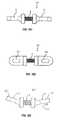
- FIG. 12Aillustrates a perspective view of a flexible connection unit having one or more spacers in between two end portions, in accordance with one embodiment of the invention.
- FIG. 12Billustrates an exploded view of the flexible connection unit of FIG. 12A .
- FIG. 12Cprovides a view of the male and female interlocking elements of the flexible connection unit of FIGS. 12A and 12B , in accordance with one embodiment of the invention.
- FIG. 13shows a perspective view of a flexible connection unit, in accordance with a further embodiment of the invention.
- FIG. 14illustrates a perspective view of a spinal fixation device in accordance with another embodiment of the invention.
- FIG. 15illustrates an exploded view of the spinal fixation device of FIG. 14 .
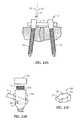
- FIG. 16Ashows a perspective view of a flexible plate connection unit in accordance with one embodiment of the invention.
- FIG. 16Billustrates a perspective view of a flexible plate connection unit in accordance with a further embodiment of the invention.
- FIG. 16Cshows a side view of the flexible plate connection unit of FIG. 16A .
- FIG. 16Dshows a top view of the flexible plate connection unit of FIG. 16A .
- FIG. 16Eillustrates a side view of the flexible plate connection unit of FIG. 16A having a pre-bent configuration in accordance with a further embodiment of the invention.
- FIG. 17is a perspective view of a flexible plate connection unit in accordance with another embodiment of the invention.
- FIG. 18illustrates a perspective view of a flexible plate connection unit in accordance with another embodiment of the invention.
- FIG. 19illustrates a perspective view of a hybrid rod-plate connection unit having a flexible middle portion according to a further embodiment of the present invention.
- FIG. 20is a perspective view of a spinal fixation device that utilizes the hybrid rod-plate connection unit of FIG. 19 .
- FIG. 21illustrates a perspective view of the spinal fixation device of FIG. 1 after it has been implanted into a patient's spinal column.
- FIGS. 22A and 22Bprovide perspective views of spinal fixation devices utilizing the plate connection units of FIGS. 16A and 16B , respectively.
- FIG. 23Aillustrates a perspective view of two pedicle screws inserted into the pedicles of two adjacent vertebrae at a skewed angle, in accordance with one embodiment of the invention.
- FIG. 23Billustrates a structural view of a coupling assembly of a pedicle screw in accordance with one embodiment of the invention.
- FIG. 23Cprovides a perspective view of a slanted stabilizing spacer in accordance with one embodiment of the invention.
- FIG. 23Dillustrates a side view of the slanted stabilizing spacer of FIG. 23C .
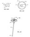
- FIG. 23Eis a top view of the cylindrical head of the pedicle screw of FIG. 23 .
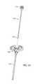
- FIG. 24illustrates a perspective view of a marking and guiding device in accordance with one embodiment of the invention.
- FIG. 25is an exploded view of the marking and guidance device of FIG. 24 .
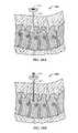
- FIG. 26Aprovides a perspective, cross-section view of a patient's spine after the marking and guiding device of FIG. 24 has been inserted during surgery.
- FIG. 26Bprovides a perspective, cross-section view of a patient's spine as an inner trocar of the marking and guiding device of FIG. 24 is being removed.
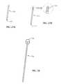
- FIGS. 27A and 27Billustrate perspective views of two embodiments of a fiducial pin, respectively.
- FIG. 28is a perspective view of a pushing trocar in accordance with a further embodiment of the invention.
- FIG. 29Aillustrates a perspective, cross-sectional view of a patient's spine as the pushing trocar of FIG. 28 is used to drive a fiducial pin into a designate location of a spinal pedicle, in accordance with one embodiment of the invention.
- FIG. 29Billustrates a perspective, cross-sectional view of a patient's spine after two fiducial pins have been implanted into two adjacent spinal pedicles, in accordance with one embodiment of the invention.
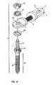
- FIG. 30is a perspective view of a cannulated awl in accordance with one embodiment of the invention.
- FIG. 31is a perspective, cross-sectional view of a patient's spine as the cannulated awl of FIG. 30 is being used to enlarge an entry hole for a pedicle screw, in accordance with one embodiment of the invention.
- FIG. 32provides a perspective view of fiducial pin retrieving device, in accordance with one embodiment of the invention.
- FIG. 33is a perspective view of a pedicle screw having an axial cylindrical cavity for receiving at least a portion of a fiducial pin therein, in accordance with a further embodiment of the invention.
- FIG. 34is a perspective, cross-sectional view of a patient's spine after one pedicle screw has been implanted into a designated location of a spinal pedicle, in accordance with one embodiment of the invention.
- FIG. 35is a perspective, cross-sectional view of a patient's spine after two pedicle screws have been implanted into designated locations of two adjacent spinal pedicles, in accordance with one embodiment of the invention.
- FIG. 36Ais perspective view of a flexible rod for spinal fixation having a spiral groove cut therein, in accordance with one embodiment of the present invention.
- FIG. 36Bprovides a cross-sectional view of the flexible rod of FIG. 36A , taken along lines B-B of FIG. 36A .
- FIG. 37Aillustrates a perspective view of a flexible rod for spinal fixation having transverse tunnels within the body of the rod, in accordance with one embodiment of the invention.
- FIG. 37Bis a cross-sectional view of the flexible rod of FIG. 37A , taken along lines B-B of FIG. 37A .
- FIG. 38Ais a perspective view of a flexible rod for spinal fixation having a spiral groove cut therein and transverse tunnels in the body of the rod, in accordance with a further embodiment of the invention.
- FIG. 38Bis a top view of the flexible rod of FIG. 38A , from the perspective of lines B-B of FIG. 38A .
- FIG. 39Ais a perspective view of a flexible rod for spinal fixation having transverse tunnels within the body of the rod, in accordance with another embodiment of the invention.
- FIG. 39Bis a cross-sectional view of the flexible rod of FIG. 39A , taken along lines B-B of that figure.
- FIG. 39Cis an alternative cross-sectional view of the flexible rod of FIG. 39A , taken along lines B-B of that figure, having substantially orthogonal transverse tunnels in the body of the rod, in accordance with a further embodiment of the invention.
- FIG. 40Aillustrates a perspective view of a flexible rod for spinal fixation, in accordance with a further embodiment of the invention.
- FIG. 40Billustrates a cross-sectional view of a flexible rod for spinal fixation in accordance with a further embodiment of the invention.
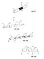
- FIG. 41Aillustrates a cross-section view of a hollow flexible rod for spinal stabilization, with an on-axis tether running through a cavity.
- FIG. 41Billustrates a cross-section view of a hollow flexible rod for spinal stabilization, with an off-axis tether running through a cavity.
- FIG. 41Cillustrates a cross-section view of a hollow flexible rod for spinal stabilization, with a pre-tensioned off-axis tether running through a cavity.
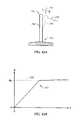
- FIG. 42Aillustrates displacement of a free end of a longitudinal body in response to an externally applied force.
- FIG. 42Bis a graph of displacement versus applied force for the system shown in FIG. 42A .
- FIG. 43illustrates a cross-sectional view of a longitudinal member with an internal tether, the tension or compression of which is adjustable according to one embodiment of the invention.
- FIG. 44illustrates a cross-sectional view of a longitudinal member with an internal tether, the tension or compression of which is adjustable, according to another embodiment of the invention.
- FIG. 45illustrates a cross-sectional view of a longitudinal member with an internal tether, the tension or compression of which is adjustable according to yet another embodiment of the invention.
- FIG. 46illustrates a perspective view of a longitudinal member similar to that shown in FIG. 45 .
- FIG. 47illustrates a longitudinal member having at least one external tether coupled to respective ends of the longitudinal member, in accordance with a further embodiment of the invention.
- FIG. 1depicts a spinal fixation device in accordance with one embodiment of the present invention.
- the spinal fixation deviceincludes two securing members 2 (designated as 2 ′ and 2 ′′), and a flexible fixation rod 4 configured to be received and secured within a coupling assembly 14 , as described in further detail below with respect to FIG. 3 .
- Each securing member 2includes a threaded screw-type shaft 10 configured to be inserted and screwed into a patient's spinal pedicle.
- the screw-type shaft 10includes an external spiral screw thread 12 formed over the length of the shaft 10 and a conical tip at the end of the shaft 10 configured to be inserted into the patient's spinal column at a designated location.
- Other known forms of the securing member 2may be used in connection with the present invention provided the securing member 2 can be inserted and fixed into the spinal column and securely coupled to the rod 4 .
- the spinal fixation deviceis used for surgical treatment of spinal diseases by mounting securing members 2 at desired positions in the spinal column.
- the rod 4extends across two or more vertebrae of the spinal column and is secured by the securing members 2 so as to stabilize movement of the two or more vertebrae.
- FIG. 2illustrates a perspective view of a spinal fixation device in accordance with a further embodiment of the present invention.
- the spinal fixation device of FIG. 2is similar to the spinal fixation device of FIG. 1 except that the rod 4 comprises a flexible middle portion 8 juxtaposed between two rigid end portions 9 of the rod 4 .
- FIG. 3provides an exploded view of the securing member 2 of FIGS. 1 and 2 illustrating various components of the coupling assembly 14 , in accordance with one embodiment of the invention.
- the coupling assembly 14includes: a cylindrical head 16 located at a top end of the screw-type shaft 10 , a spiral thread or groove 18 formed along portions of the inner wall surface of the cylindrical head 16 , and a U-shaped seating groove 20 configured to receive the rod 4 therein.
- the coupling assembly 14further comprises an outside-threaded nut 22 having a spiral thread 24 formed on the outside lateral surface of the nut 22 , wherein the spiral thread 24 is configured to mate with the internal spiral thread 18 of the cylindrical head 16 .
- the coupling assembly 14includes a fixing cap 26 configured to be mounted over a portion of the cylindrical head 16 to cover and protect the outside-threaded nut 22 and more securely hold rod 4 within seating groove 20 .
- an inner diameter of the fixing gap 26is configured to securely mate with the outer diameter of the cylindrical head 16 .
- Other methods of securing the fixing cap 26 to the cylindrical head, such as correspondingly located notches and groove (not shown),would be readily apparent to those of skill in the art.
- the components and parts of the securing member 2may be made of highly rigid and durable bio-compatible materials such as: stainless steel, iron steel, titanium or titanium alloy. Such materials are known in the art.
- bio-compatible materialsrefers to those materials that will not cause any adverse chemical or immunological reactions after being implanted into a patient's body.
- the rod 4is coupled to the securing means 2 by seating the rod 4 horizontally into the seating groove 20 of the coupling means 14 perpendicularly to the direction of the length of the threaded shaft 10 of securing member 2 .
- the outside threaded nut 22is then received and screwed into the cylindrical head 16 above the rod 4 so as to secure the rod 4 in the seating groove 20 .
- the fixing cap 26is then placed over the cylindrical head 16 to cover, protect and more firmly secure the components in the internal cavity of the cylindrical head 16 .
- FIGS. 4-7illustrate perspective views of various embodiments of a rod 4 that may be used in a fixation device, in accordance with the present invention.
- FIG. 4illustrates the rod 4 of FIG.
- rod 4comprises a metal tube or pipe having a cylindrical wall 5 of a predefined thickness.
- the cylindrical wall 5is cut in a spiral fashion along the length of the rod 4 to form spiral cuts or grooves 6 .
- the width and density of the spiral grooves 6may be adjusted to provide a desired level of flexibility.
- the grooves 6are formed from very thin spiral cuts or incisions that penetrate through the entire thickness of the cylindrical wall of the rod 4 .
- the thickness and material of the tubular walls 5also affect the level of flexibility.
- the rod 4is designed to have a flexibility that substantially equals that of a normal back. Flexibility ranges for a normal back are known by those skilled in the art, and one of ordinary skill can easily determine a thickness and material of the tubular walls 5 and a width and density of the grooves 6 to achieve a desired flexibility or flexibility range within the range for a normal back.
- the term “density”refers to tightness of the spiral grooves 6 or, in other words, the distance between adjacent groove lines 6 as shown in FIG. 4 , for example.
- the present inventionis not limited to a particular, predefined flexibility range.
- the rigidity of the rod 4should be able to endure a vertical axial load applied to the patient's spinal column along a vertical axis of the spine in a uniform manner with respect to the rest of the patient's natural spine.
- FIG. 5illustrates the rod 4 of FIG. 2 wherein only a middle portion 8 is made and designed to be flexible and two end portions 9 are made to be rigid.
- metal end rings or caps 9 ′having no grooves therein, may be placed over respective ends of the rod 4 of FIG. 4 so as make the end portions 9 rigid.
- the rings or caps 9 ′may be permanently affixed to the ends of the rod 4 using known methods such as pressing and/or welding the metals together.
- the spiral groove 6is only cut along the length of the middle portion 8 and the end portions 9 comprise the tubular wall 5 without grooves 6 . Without the grooves 6 , the tubular wall 5 , which is made of a rigid metal or metal hybrid material, exhibits high rigidity.
- FIG. 6illustrates a further embodiment of the rod 4 having multiple sections, two flexible sections 8 interleaved between three rigid sections 9 .
- This embodimentmay be used, for example, to stabilize three adjacent vertebrae with respect to each other, wherein three pedicle screws are fixed to a respective one of the vertebrae and the three rigid sections 9 are connected to a coupling assembly 14 of a respective pedicle screw 2 , as described above with respect to FIG. 3 .
- Each of the flexible sections 8 and rigid sections 9may be made as described above with respect to FIG. 5 .
- FIG. 7illustrates another embodiment of the rod 4 having a pre-bent structure and configuration to conform to and maintain a patient's curvature of the spine, known as “lordosis,” while stabilizing the spinal column.
- a patient's lumbaris in the shape of a ‘C’ form, and the structure of the rod 4 is formed to coincide to the normal lumbar shape when utilized in the spinal fixation device of FIG. 2 , in accordance with one embodiment of the invention.
- the pre-bent rod 4includes a middle portion 8 that is made and designed to be flexible interposed between two rigid end portions 9 .
- the middle portion 8 and end portions 9may be made as described above with respect to FIG. 5 .
- the pre-bent structure and design of the rod 4may offset a skew angle when two adjacent pedicle screws are not inserted parallel to one another, as described in further detail below with respect to FIG. 23A .
- FIG. 8illustrates a perspective, cross-sectional view of a flexible tubular rod 4 , or rod portion 8 in accordance with one embodiment of the invention.
- the flexible rod 4 , 8is made from a first metal tube 5 having a spiral groove 6 cut therein as described above with respect to FIGS. 4-7 .
- a second tube 30 having spiral grooves 31 cut therein and having a smaller diameter than the first tube 5is inserted into the cylindrical cavity of the first tube 5 .
- the second tube 30has spiral grooves 31 which are cut in an opposite spiral direction with respect to the spiral grooves 6 cut in the first tube 5 , such that the rotational torsion characteristics of the second tube 30 offset at least some of the rotational torsion characteristics of the first tube 5 .
- the second flexible tube 30is inserted into the core of the first tube to provide further durability and strength to the flexible rod 4 , 8 .
- the second tube 30may be made of the same or different material than the first tube 5 .
- the material used to manufacture the first and second tubes 5 and 30may be any one or combination of the following exemplary metals: stainless steel, iron steel, titanium, and titanium alloy.
- FIG. 9illustrates a perspective, cross-sectional view of a flexible rod 4 , 8 in accordance with a further embodiment of the invention.
- the flexible rod 4 , 8includes an inner core made of a metallic wire 32 comprising a plurality of overlapping thin metallic yarns, such as steel yarns, titanium yarns, or titanium-alloy yarns.
- the wire 32is encased by a metal, or metal hybrid, flexible tube 5 having spiral grooves 6 cut therein, as discussed above.
- the number and thickness of the metallic yarns in the wire 32also affects the rigidity and flexibility of the rod 4 , 8 . By changing the number, thickness or material of the yarns flexibility can be increased or decreased.
- the number, thickness and/or material of the metallic yarns in the wire 32can be adjusted to provide a desired rigidity and flexibility in accordance with a patient's particular needs.
- Those of ordinary skill in the artcan easily determine the number, thickness and material of the yarns, in conjunction with a given flexibility of the tube 5 in order to achieve a desired rigidity v. flexibility profile for the rod 4 , 8 .
- FIG. 10shows yet another embodiment of a flexible rod 4 wherein the flexible tube 5 encases a non-metallic, flexible core 34 .
- the core 34may be made from known biocompatible shape memory alloys (e.g., NITINOL), or biocompatible synthetic materials such as: carbon fiber, Poly Ether Ether Ketone (PEEK), Poly Ether Ketone Ketone Ether Ketone (PEKKEK), or Ultra High Molecular Weight Poly Ethylene (UHMWPE).
- NITINOLknown biocompatible shape memory alloys
- PEEKPoly Ether Ether Ketone
- PEKKEKPoly Ether Ketone Ketone Ether Ketone
- UHMWPEUltra High Molecular Weight Poly Ethylene
- FIG. 11illustrates a perspective view of another embodiment of the flexible rod 35 in which a plurality of metal wires 32 , as described above with respect to FIG. 9 , are interweaved or braided together to form a braided metal wire rod 35 .
- the braided metal wire rod 35can be made from the same materials as the metal wire 32 .
- the rigidity and flexibility of the braided rod 35can be further modified to achieve desired characteristics by varying the number and thickness of the wires 32 used in the braided structure 35 .
- each end of the braided metal wire rod 35is encased by a rigid metal cap or ring 9 ′ as described above with respect to FIGS. 5-7 , to provide a rod 4 having a flexible middle portion 8 and rigid end portions 9 .
- the metal braided wire rod 35may be utilized as a flexible inner core encased by a metal tube 5 having spiral grooves 6 cut therein to create a flexible metal rod 4 or rod portion 8 , in a similar fashion to the embodiments shown in FIGS. 8-10 .
- the term “braid” or “braided structure”encompasses two or more wires, strips, strands, ribbons and/or other shapes of material interwoven in an overlapping fashion. Various methods of interweaving wires, strips, strands, ribbons and/or other shapes of material are known in the art. Such interweaving techniques are encompassed by the present invention.
- the flexible metal rod 35includes a braided metal structure having two or more metal strips, strands or ribbons interweaved in a diagonally overlapping pattern.
- FIG. 12Aillustrates a further embodiment of a flexible connection unit 36 having two rigid end portions 9 ′ and an exemplary number of rigid spacers 37 .
- the rigid end portions 9 ′ and spacerscan be made of bio-compatible metal or metal-hybrid materials as discussed above.
- the connection unit 36further includes a flexible wire 32 , as discussed above with respect to FIG. 9 ′, which traverses an axial cavity or hole (not shown) in each of the rigid end portions 9 ′ and spacers 37 .
- FIG. 12Billustrates an exploded view of the connection unit 36 that further shows how the wire 32 is inserted through center axis holes of the rigid end portions 9 ′ and spacers 37 . As further shown in FIG.
- each of the end portions 9 ′ and spacers 37include a male interlocking member 38 which is configured to mate with a female interlocking cavity (not shown) in the immediately adjacent end portion 9 ′ or spacer 37 .
- FIG. 12Cillustrates an exploded side view and indicates with dashed lines the location and configuration of the female interlocking cavity 39 for receiving corresponding male interlocking members 38 .
- FIG. 13shows a perspective view of a flexible connection unit 40 in accordance with another embodiment of the invention.
- the connection 40is similar to the connection unit 36 described above, however, the spacers 42 are configured to have the same shape and design as the rigid end portions 9 ′. Additionally, the end portions 9 ′ have an exit hole or groove 44 located on a lateral side surface through which the wire 32 may exit, be pulled taut, and clamped or secured using a metal clip 43 or other known techniques. In this way, the length of the flexible connection unit 36 or 40 may be varied at the time of surgery to fit each patient's unique anatomical characteristics. In one embodiment, the wire 32 may be secured using a metallic clip or stopper 43 .
- a clip or stoppermay include a small tubular cylinder having an inner diameter that is slightly larger than the diameter of the wire 32 to allow the wire 32 to pass therethrough. After the wire 32 is pulled to a desired tension through the tubular stopper, the stopper 43 is compressed so as to pinch the wire 32 contained therein.
- the wire 32may be pre-secured using known techniques during the manufacture of the connection units 36 , 40 having a predetermined number of spacers 37 , 42 therein.
- FIG. 14depicts a spinal fixation device according to another embodiment of the present invention.
- the spinal fixation deviceincludes: at least two securing members 2 containing an elongate screw type shaft 10 having an external spiral thread 12 , and a coupling assembly 14 .
- the devicefurther includes a plate connection unit 50 , or simply “plate 50 ,” configured to be securely connected to the coupling parts 14 of the two securing members 2 .
- the plate 50comprises two rigid connection members 51 each having a planar surface and joined to each other by a flexible middle portion 8 .
- the flexible middle portion 8may be made in accordance with any of the embodiments described above with respect to FIGS. 4-11 .
- Each connection member 51contains a coupling hole 52 configured to receive therethrough a second threaded shaft 54 ( FIG. 15 ) of the coupling assembly 14 .
- the coupling assembly 14 of the securing member 2includes a bolt head 56 adjoining the top of the first threaded shaft 10 and having a circumference or diameter greater than the circumference of the first threaded shaft 10 .
- the second threaded shaft 54extends upwardly from the bolt head 56 .
- the coupling assembly 14further includes a nut 58 having an internal screw thread configured to mate with the second threaded shaft 54 , and one or more washers 60 , for clamping the connection member 51 against the top surface of the bolt head 56 , thereby securely attaching the plate 50 to the pedicle screw 2 .
- FIGS. 16A and 16Billustrate two embodiments of a plate connection unit 40 having at least two coupling members 51 and at least one flexible portion 8 interposed between and attached to two adjacent connection members 51 .
- the flexible middle portion 8comprises a flexible metal braided wire structure 36 as described above with respect to FIG. 11 .
- the flexible portion 8can be designed and manufactured in accordance with any of the embodiments described above with respect to FIGS. 4-11 , or combinations thereof.
- FIGS. 16C and 16Dillustrate a side view and top view, respectively, of the plate 50 of FIG. 16A .
- the manufacture of different embodiments of the flexible connection units 50 and 58 having different types of flexible middle portions 8is easily accomplished using known metallurgical, organic polymer, natural resin, or composite materials, and compatible manufacturing and machining processes.
- FIG. 16Eillustrate a side view of a pre-bent plate connection unit 50 ′, in accordance with a further embodiment of the invention.
- This plate connection unit 50 ′is similar to the plate 50 except that connection members 51 ′ are formed or bent at an angle ⁇ from a parallel plane 53 during manufacture of the plate connection unit 50 ′.
- this pre-bent configurationis designed to emulate and support a natural curvature of the spine (e.g., lordosis). Additionally, or alternatively, this pre-bent structure may offset a skew angle when two adjacent pedicle screws are not inserted parallel to one another, as described in further detail below with respect to FIG. 23A .
- FIG. 17illustrates a perspective view of a plate connection unit 60 having two planar connection members 62 each having a coupling hole 64 therein for receiving the second threaded shaft 44 of the pedicle screw 2 .
- a flexible middle portion 8is interposed between the two connection members 62 and attached thereto.
- the flexible middle portion 8is made in a similar fashion to wire 32 described above with respect to FIG. 9 , except it has a rectangular configuration instead of a cylindrical or circular configuration as shown in FIG. 9 . It is understood, however, that the flexible middle portion 8 may be made in accordance with the design and materials of any of the embodiments previously discussed.
- FIG. 18illustrates a perspective view of a further embodiment of the plate 60 of FIG. 17 wherein the coupling hole 64 includes one or more nut guide grooves 66 cut into the top portion of the connection member 62 to seat and fix the nut 58 ( FIG. 15 ) into the coupling hole 64 .
- the nut guide groove 66is configured to receive and hold at least a portion of the nut 58 therein and prevent lateral sliding of the nut 58 within the coupling hole 64 after the connection member 62 has been clamped to the bolt head 56 of the pedicle screw 2 .
- FIG. 19illustrates a perspective view of a hybrid plate and rod connection unit 70 having a rigid rod-like connection member 4 , 9 or 9 ′, as described above with respect to FIGS. 4-7 , at one end of the connection unit 70 and a plate-like connection member 51 or 62 , as described above with respect to FIGS. 14-18 , at the other end of the connection unit 70 .
- a flexible member 8interposed between rod-like connection member 9 ( 9 ′) and the plate-like connection member 52 ( 64 ) is a flexible member 8 .
- the flexible member 8may be designed and manufactured in accordance with any of the embodiments discussed above with reference to FIGS. 8-13 .
- FIG. 20illustrates a perspective view of a spinal fixation device that utilizes the hybrid plate and rod connection unit 70 of FIG. 19 .
- this fixation deviceutilizes two types of securing members 2 (e.g., pedicle screws), the first securing member 2 ′ being configured to securely hold the plate connection member 42 ( 64 ) as described above with respect to FIG. 15 , and the second securing member 2 ′′ being configured to securely hold the rod connection member 4 , 9 or 9 ′, as described above with respect to FIG. 3 .
- securing members 2e.g., pedicle screws
- FIG. 21illustrates a perspective top view of two spinal fixation devices, in accordance with the embodiment illustrated in FIG. 1 , after they are attached to two adjacent vertebrae 80 and 82 to flexibly stabilize the vertebrae.
- FIGS. 22A and 22Billustrate perspective top views of spinal fixation devices using the flexible stabilizing members 50 and 58 of FIGS. 16A and 16B , respectively, after they are attached to two or more adjacent vertebrae of the spine.
- FIG. 23Aillustrates a side view of a spinal fixation device after it has been implanted into the pedicles of two adjacent vertebrae.
- the pedicle screws 2are mounted into the pedicle bone such that a center axis 80 of the screws 2 are offset by an angle ⁇ from a parallel plane 82 and the center axes 80 of the two screws 2 are offset by an angle of approximately 2 ⁇ from each other.
- This type of non-parallel insertion of the pedicle screws 2often results due to the limited amount of space that is available when performing minimally invasive surgery.
- the pedicle screws 2may have a tendency to be skewed from parallel due to a patient's natural curvature of the spine (e.g., lordosis). Thus, due to the non-parallel nature of how the pedicle screws 2 are ultimately fixed to the spinal pedicle, it is desirable to offset this skew when attaching a rod or plate connection unit to each of the pedicle screws 2 .
- FIG. 23Billustrates a side view of the head of the pedicle screw in accordance with one embodiment of the invention.
- the screw 2includes a cylindrical head 84 which is similar to the cylindrical head 16 described above with respect to FIG. 3 except that the cylindrical head 84 includes a slanted seat 86 configured to receive and hold a flexible rod 4 in a slanted orientation that offsets the slant or skew ⁇ of the pedicle screw 2 as described above.
- the improved pedicle screw 2further includes a slanted stabilizing spacer 88 which is configured to securely fit inside the cavity of the cylindrical head 84 and hold down the rod 4 at the same slant as the slanted seat 86 .
- the pedicle screw 2further includes an outside threaded nut 22 configured to mate with spiral threads along the interior surface (not shown) of the cylindrical head 84 for clamping down and securing the slanted spacer 88 and the rod 4 to the slanted seat 86 and, hence, to the cylindrical head 84 of the pedicle screw 2 .
- FIG. 23Cshows a perspective view of the slanted spacer 88 , in accordance with embodiment of the invention.
- the spacer 88includes a circular middle portion 90 and two rectangular-shaped end portions 92 extending outwardly from opposite sides of the circular middle portion 90 .
- FIG. 23Dshows a side view of the spacer 88 that further illustrates the slant from one end to another to compensate or offset the skew angle ⁇ of the pedicle screw 2 .
- FIG. 23Eillustrates a top view of the cylindrical head 84 configured to receive a rod 4 and slanted spacer 88 therein.
- the rod 4is received through two openings or slots 94 in the cylindrical walls of the cylindrical head 84 , which allow the rod 4 to enter the circular or cylindrical cavity 96 of the cylindrical head 84 and rest on top of the slanted seat 86 formed within the circular or cylindrical cavity 94 .
- the slanted stabilizing spacer 88is received in the cavity 96 such that the two rectangular-shaped end portions 92 are received within the two slots 94 , thereby preventing lateral rotation of the spacer 88 within the cylindrical cavity 96 .
- the outside threaded nut 22 and fixing cap 26are inserted on top of the slanted spacer 88 to securely hold the spacer 88 and rod 4 within the cylindrical head 84 .
- FIG. 24illustrates a perspective view of a marking and guidance device 100 for marking a desired location on the spinal pedicle where a pedicle screw 2 will be inserted and guiding the pedicle screw 2 to the marked location using a minimally invasive surgical technique.
- the marking device 100includes a tubular hollow guider 52 which receives within its hollow an inner trocar 104 having a sharp tip 105 at one end that penetrates a patient's muscle and tissue to reach the spinal pedicle.
- the inner trocar 104further includes a trocar grip 106 at the other end for easy insertion and removal of the trocar 104 .
- the marking and guidance device 100includes a guider handle 108 to allow for easier handling of the device 100 .
- the trocar 104is in the form of a long tube or cylinder having a diameter smaller than the inner diameter of the hollow of the guider 102 so as to be inserted into the hollow of the tubular guider 102 .
- the trocar 104further includes a sharp or pointed tip 105 for penetrating the vertebral body through the pedicle.
- the trocar 104further includes a trocar grip 106 having a diameter larger than the diameter of the hollow of the guider tube 102 in order to stop the trocar 104 from sliding completely through the hollow.
- the trocar grip 106also allows for easier handling of the trocar 104 .
- FIGS. 26A and 26Bprovide perspective views of the marking and guidance device 100 after it has been inserted into a patient's back and pushed through the muscle and soft tissue to reach a desired location on the spinal pedicle.
- the desired locationis determined using known techniques such as x-ray or radiographic imaging for a relatively short duration of time.
- prolonged exposure of the patient to x-ray radiationis unnecessary.
- the inner trocar 104is removed to allow fiducial pins (not shown) to be inserted into the hollow of the guidance tube 102 and thereafter be fixed into the pedicle.
- FIGS. 27A and 27Billustrate perspective views of two embodiments of the fiducial pins 110 and 112 , respectively.
- the fiducial pins 110 and 112according to the present invention are inserted and fixed into the spinal pedicle after passing through the hollow guider 102 .
- the pins 110 and 112have a cylindrical shape with a diameter smaller than the inner diameter of the hollow of the guider tube 102 in order to pass through the hollow of the guider 102 .
- An end of each fiducial pinis a sharp point 111 configured to be easily inserted and fixed into the spinal pedicle of the spinal column. In one embodiment, as shown in FIG.
- the other end of the fiducial pinincorporates a threaded shaft 114 which is configured to mate with an internally threaded tube of a retriever (not shown) for extraction of the pin 112 .
- This retrieveris described in further detail below with respect to FIG. 32 .
- the fiducial pins 110 , 112are preferably made of a durable and rigid biocompatible metal (e.g., stainless steel, iron steel, titanium, titanium alloy) for easy insertion into the pedicle bone.
- a durable and rigid biocompatible metale.g., stainless steel, iron steel, titanium, titanium alloy
- the fiducial pins 110 , 112are easily driven into the spinal pedicle without risk of bending or structural failure.
- the process of driving in prior art guidance wireswas often very difficult and time-consuming.
- the insertion of the fiducial pins 110 , 112 into the entry point on the spinal pedicleis much easier and convenient for the surgeon and, furthermore, does not hinder subsequent procedures due to a guide wire protruding out of the patient's back.
- FIG. 28shows a cylindrical pushing trocar 116 having a cylindrical head 118 of larger diameter than the body of the pushing trocar 116 .
- the pushing trocar 116is inserted into the hollow of the guider 102 after the fiducial pin 110 or 112 has been inserted into the hollow of the guider 102 to drive and fix the fiducial pin 110 or 112 into the spinal pedicle.
- a doctorstrikes the trocar head 118 with a chisel or a hammer to drive the fiducial pin 110 and 112 into the spinal pedicle.
- the pushing trocar 116is in the form of a cylindrical tube, which has a diameter smaller than the inner diameter of the hollow of the guider tube 112 .
- the pushing trocar 116also includes a cylindrical head 118 having a diameter larger than the diameter of the pushing trocar 116 to allow the doctor to strike it with a chisel or hammer with greater ease.
- a hammer or chiselis not necessarily required.
- a surgeonmay choose to push or tap the head 118 of the pushing trocar 116 with the palm of his or her hand or other object.
- FIG. 29Aillustrates how a hammer or mallet 120 and the pushing trocar 116 may be used to drive the pin 110 , 112 through the hollow of the guider tube 102 and into the designated location of the spinal pedicle.
- FIG. 29Billustrates a perspective cross-sectional view of the spinal column after two fiducial pins 110 , 112 have been driven and fixed into two adjacent vertebrae.
- a larger hole or area centered around each pin 110 , 112is created to allow easer insertion and mounting of a pedicle screw 2 into the pedicle bone.
- the larger holeis created using a cannulated awl 122 as shown in FIG. 30 .
- the cannulated awl 122is inserted over the fiducial pin 110 , 112 fixed at the desired position of the spinal pedicle.
- the awl 122is in the form of a cylindrical hollow tube wherein an internal diameter of the hollow is larger than the outer diameter of the fiducial pins 110 and 112 so that the pins 110 , 112 may be inserted into the hollow of the awl 122 .
- the awl 122further includes one or more sharp teeth 124 at a first end for cutting and grinding tissue and bone so as to create the larger entry point centered around the fiducial pin 110 , 112 so that the pedicle screw 2 may be more easily implanted into the spinal pedicle.
- FIG. 31illustrates a perspective cross-sectional view of a patient's spinal column when the cannulated awl 122 is inserted into a minimally invasive incision in the patient's back, over a fiducial pin 110 , 112 to create a larger insertion hole for a pedicle screw 2 (not shown).
- a retractor 130has been inserted into the minimally invasive incision over the surgical area and a lower tubular body of the retractor 130 is expanded to outwardly push surrounding tissue away from the surgical area and provide more space and a visual field for the surgeon to operate.
- the minimally invasive incisionis made in the patient's back between and connecting the two entry points of the guide tube 102 used to insert the two fiducial pins 110 , 112 .
- prior expansion of the minimally invasive incisionis typically required using a series of step dilators (not shown), each subsequent dilator having a larger diameter than the previous dilator.
- the retractor 130is inserted with its lower tubular body in a retracted, non-expanded state. After the retractor 130 is pushed toward the spinal pedicle to a desired depth, the lower tubular portion is then expanded as shown in FIG. 31 .
- step dilators and retractorsare well known in the art.
- the fiducial pin 110 , 112is removed.
- a retrieving device 140may be used to remove the fiducial pin 112 before implantation of a pedicle screw 2 .
- the retriever 140comprises a long tubular or cylindrical portion having an internally threaded end 142 configured to mate with the externally threaded top portion 114 of the fiducial pin 112 .
- a doctormy pull the fiducial pin 112 out of the spinal pedicle.
- appropriate toolse.g., specially designed needle nose pliers
- the fiducial pins 110 , 112are not extracted from the spinal pedicle. Instead, a specially designed pedicle screw 144 may be inserted into the spinal pedicle over the pin 110 , 112 without prior removal of the pin 110 , 112 .
- the specially designed pedicle screw 144includes an externally threaded shaft 10 and a coupling assembly 14 ( FIG. 3 ) that includes a cylindrical head 16 ( FIG. 3 ) for receiving a flexible rod-shaped connection unit 4 ( FIGS. 4-13 ).
- the coupling assembly 14may be configured to receive a plate-like connection unit as shown in FIGS. 14-20 .
- the pedicle screw 144further includes a longitudinal axial channel (not shown) inside the threaded shaft 10 having an opening 146 at the tip of the shaft 10 and configured to receive the fiducial pin 110 , 112 therein.
- FIG. 34illustrates a perspective cross-sectional view of the patient's spinal column after a pedicle screw 2 has been inserted into a first pedicle of the spine using an insertion device 150 .
- Various types of insertion devices 150 known in the artmay be used to insert the pedicle screw 2 .
- the retractor 130is adjusted and moved slightly to provide space and a visual field for insertion of a second pedicle screw at the location of the second fiducial pin 110 , 112 .
- FIG. 35provides a perspective, cross sectional view of the patient's spinal column after two pedicle screws 2 have been implanted in two respective adjacent pedicles of the spine, in accordance with the present invention.
- a flexible rod, plate or hybrid connection unitas described above with respect to FIGS. 4-20 may be connected to the pedicle screws to provide flexible stabilization of the spine.
- the retractor 130is removed and the minimally invasive incision is closed and/or stitched.
- FIG. 36Aillustrates a perspective view of a flexible rod 200 for spinal fixation, in accordance with a further embodiment of the invention.
- the rod 200is configured to be secured by securing members 2 as described above with reference to FIGS. 1-3 .
- the rod 200 , and rods 210 , 220 , 230 and 240 described beloware comprised of a solid, cylindrically-shaped rod made of known bio-compatible materials such as: stainless steel, iron steel, titanium, titanium alloy, NITINOL, and other suitable metal compositions or materials.
- spiral grooves 202are cut or formed along at least a portion of the length of the cylindrical body of the rod 200 .
- the length of the rod “1”may be between 4 and 8 centimeters (cm), and its cylindrical diameter “D” is between 4-8 millimeters (mm).
- the spiral grooves 202have a width “w” between 0.1 and 0.5 mm and a spiral angle ⁇ between 50 and 85 degrees from horizontal.
- the distance between spiral grooves 202can be between 3 and 6 mm.
- the above dimensionsare exemplary only and may be varied to achieve desired flexibility, torsion and strength characteristics that are suitable for a particular patient or application.
- FIG. 36Billustrates a cross-sectional view of the flexible rod 200 , taken along lines B-B of FIG. 36A .
- spiral groove 202is cut toward the center longitudinal axis of the cylindrical rod 200 .
- the groovemay be formed continuously in a spiral fashion, as a helix or an interrupted helix for a solid or hollow rod, or are as disconnected circumferential grooves for a solid rod. If hollow rods have disconnected circumferential grooves formed in them, the grooves can only partially penetrate the rod material to avoid discontinuities.
- the depth of the groove 202is approximately equal to the cylindrical radius of the rod 200 , as shown in FIG. 36B , and penetrates as deep as the center longitudinal axis of the cylindrical rod 200 .
- the cross sectional area and shape of the rod, groove depth, groove width, groove cross-section shape, and groove to groove spacing of the grooved portion of the longitudinal membercan be varied to adjust mechanical and structural characteristics as desired. For example, deepening or widening grooves increases flexibility, while increasing groove-to-groove spacing decreases flexibility. This can be used to modify extent of rod bending at a fixed bending force, custom tailor the bent shape of the rod, and equalize mechanical stresses in the rod during bending in order to minimize material fatigue and improve rod reliability.
- FIG. 37Aillustrates a flexible rod 210 for spinal fixation in accordance with another embodiment of the invention.
- the rod 210includes a plurality of transverse holes or tunnels 212 drilled or formed within the body of the rod 210 .
- the tunnels 212pass through a center longitudinal axis of the cylindrical rod 210 at an angle ⁇ from horizontal.
- the openings for each respective tunnel 212are located on opposite sides of the cylindrical wall of the rod 210 and adjacent tunnels 212 share a common opening on one side of the cylindrical wall, forming a zigzag pattern of interior tunnels 212 passing transversely through the central longitudinal axis of the rod 210 , as shown in FIG. 37A .
- the diameter D of each tunnel 212may be varied between 0.2 to 3 mm, depending the desired mechanical and structural characteristics (e.g., flexibility, torsion and strength) of the rod 210 .
- desired mechanical and structural characteristicse.g., flexibility, torsion and strength
- these dimensionsare exemplary and other diameters D may be desired depending on the materials used and the desired structural and mechanical characteristics.
- the angle from horizontal ⁇may be varied to change the number of tunnels 212 or the distance between adjacent tunnels 212 .
- FIG. 37Billustrates a cross-sectional view of the flexible rod 210 taken along lines B-B of FIG. 37A .
- the tunnel 212cuts through the center cylindrical axis of the rod 210 such that openings of the tunnel 212 are formed at opposite sides of the cylindrical wall of the rod 210 .
- FIG. 38Aillustrates a perspective view of a flexible rod 220 for spinal fixation, in accordance with a further embodiment of the invention.
- Rod 220incorporates the spiral grooves 202 described above with reference to FIGS. 36A and 36B as well as the transverse tunnels 212 described above with respect to FIGS. 37A and 37B .
- the spiral grooves 202are cut into the surface of the cylindrical wall of the rod 220 toward a center longitudinal axis of the rod 220 .
- the dimensions of the spiral grooves 202 and their angle from horizontal ⁇may be varied in accordance with desired mechanical and structural characteristics.
- the dimensions of the transverse tunnels 212 and their angle from horizontal ⁇FIG.
- angles ⁇ and ⁇are substantially similar such that the openings of the tunnels 212 substantially coincide with the spiral grooves 202 on opposite sides of the cylindrical wall of the rod 220 .
- FIG. 38Bshows a top view of the flexible rod 220 taken along the perspective indicated by lines B-B of FIG. 38A .
- the openings of the tunnels 212coincide with the spiral grooves 202 .
- FIG. 39Aillustrates a flexible rod 230 for spinal fixation, in accordance with another embodiment of the invention.
- the rod 230includes a plurality of transverse tunnels 232 formed in the body of the rod 230 .
- the tunnels 232are substantially similar to the tunnels 212 described above with respect to FIGS. 37A and 37B , however, the tunnels 232 are not linked together in a zigzag pattern. Rather, each tunnel 232 is substantially parallel to its immediate adjacent tunnels 232 and the openings of one tunnel 232 do not coincide with the openings of adjacent tunnels 232 .
- the angle from horizontal ⁇ in this embodimentis approximately 90 degrees. However, it is understood that other angles ⁇ may be incorporated in accordance with the present invention.
- tunnels 232may be varied to achieve desired mechanical and structural characteristics.
- the cross-sectional shape of the tunnels 212 and 232need not be circular. Instead, for example, they may be an oval or diamond shape, or other desired shape.
- FIG. 39Billustrates a cross-sectional view of the rod 230 taken along lines B-B of FIG. 39A .
- the transverse tunnel 232travels vertically and transversely through the center longitudinal axis of the rod 230 .
- FIG. 39Cillustrates a cross-sectional view of a further embodiment of the rod 230 , wherein an additional transverse tunnel 232 ′ is formed substantially orthogonal to the first transverse tunnel 232 and intersects the first transverse tunnel 232 at the center, cylindrical axis point. In this way, further flexibility of the rod 230 may be provided as desired.
- FIG. 40Aillustrates a perspective view of a flexible rod 240 , in accordance with a further embodiment of the invention.
- the rod 240includes a plurality of interleaved transverse tunnels 232 and 242 which are substantially orthogonal to each other and which do not intersect, as shown in FIG. 40A .
- adjacent tunnels 232 and 242need not be orthogonal to one another.
- Each tunnel 232 , 242can be offset at a desired angle (o from its immediately preceding adjacent tunnel 232 , 242 .
- FIG. 41Aillustrates a cross-sectional view of an embodiment of the invention with a longitudinal member for a spinal stabilization system having a flexible section 284 between ends 280 and 282 that are configured to mate with securing member 2 of FIG. 3 .
- FIG. 41Afurther illustrates that the flexible section 284 is hollow, having a cavity 287 through which runs a tether 286 that is coupled to ends 280 and 282 .
- Various exemplary methods of coupling the tether 286 to each of the ends 280 and 282 of the longitudinal memberare described in further detail below with reference to FIGS. 43-46 .
- FIG. 42Ais a graph illustrating displacement (d) of the longitudinal member as a function of externally applied bending force (f).
- the increase in bending resistancei.e. reduced displacement in response to increasing force serves to limit the bending range of the longitudinal member to (dt) 295 , and thereby limit the bending range of the spinal stabilization system, beyond which further bending of the spine is limited.
- FIG. 41BIllustrates a cross-sectional view of an embodiment with a longitudinal member as in FIG. 41A , except that tether 286 is attached at a position offset from central axis 382 of the longitudinal member, thereby differentially limiting the bending range differently in different bending directions because the tether becomes taught at angularly dependent magnitudes of displacement (d) of FIG. 42A , thereby directionally limiting the bending range of flexible spinal stabilization system beyond which further bending of the spine is limited.
- FIG. 41Cillustrates a cross-sectional view of an embodiment with a longitudinal member as in FIG. 41B , except that the tether 290 is pre-tensioned resulting in a longitudinal member that is bent in the absence of an externally applied force, so that the longitudinal member is pre-shaped to conform to a curved region of a spine.
- the directionally limited bending range discussed aboveis also a feature of the embodiment illustrated in 41 C, except that displacement of the longitudinal member is substantially limited in one direction for selectively stabilizing or adjusting deformities of the spine.
- FIG. 43shows a cross-sectional view of an embodiment of a longitudinal member as in FIG. 41A except that one end of tether 308 is coupled to an adjustable member 316 .
- adjustable member 316is a cylindrical piece with an externally threaded section 312 that mates with an internally threaded section 303 of an end 302 of the longitudinal member.
- Tether 308is non-rotatably secured to end 300 of the longitudinal member.
- Slot 314 of adjustable member 316is exemplary of a screwdriver slot or internal hex for axially rotating adjustable member 316 .
- Rotating slip joint 317permits adjustable member 316 to axially rotate while tether 308 does not rotate, while transmitting axially directed force from adjustable member 316 to tether 308 , allowing the application of compression or tension to tether 308 by rotationally adjusting adjustable member 316 , resulting in axial displacement of adjustable member 316 .
- Thisprovides an easy, reversible way to adjust the tension on the tether 308 .
- the adjustable member 314can be positioned off central axis 283 to provide different bending characteristics of the longitudinal member in different bending directions as discussed above in relation to FIG. 41B , or to additionally provide a bend in the longitudinal body as discussed above in relation to FIG. 41C .
- FIG. 44shows a cross-section of a longitudinal body for another embodiment as in FIG. 43 , except that in FIG. 44 , the tether 308 is non-rotatably attached to an adjustable member 313 having external threads thereon.
- a rotating slip joint 319permits adjustable member 313 to axially rotate together with tether 308 , while axially anchoring tether 308 to end 300 of the longitudinal member, allowing the application of compression or tension to tether 308 by rotationally adjusting adjustable member 313 . This provides an easy, reversible way to adjust the tension on the tether.
- FIG. 45shows a cross-section of yet another embodiment.
- tether 308is non-rotatably anchored to end 300 of the longitudinal body, and extends beyond the end 302 of the longitudinal body to an externally threaded section 315 .
- An external nut 318has an internally threaded section configured to mate with the externally threaded section 315 and may, when torqued, abut end 302 , thereby applying tension to tether 308 .
- the external nut 318is exemplary of a locking member for securing the threaded section 315 in a fixed position after a desired tension on the tether 308 has been achieved.
- a washer 320may be interposed between nut 318 and end 302 .
- the washer 320may be a plain washer to eliminate wear and rotational friction between the adjoining surfaces of end 302 and nut 318 , or it may be a locking type washer to resist the rotation of nut 318 relative to end 302 and prevent inadvertent loosening. Alternately, the washer 320 may be a combination of the two types of washers. Locking washers can come in a simple split ring configuration or a more elaborate design, all of which are well known in the mechanical art.
- FIG. 46illustrates a perspective view of a longitudinal member similar to the embodiment shown in FIG. 45 .
- the longitudinal members shown in FIG. 41 and FIGS. 43 through 46are fabricated of a biocompatible material, suitable for implantation in the human body as discussed above. Additionally the adjustable members 316 and 313 of FIGS. 43 and 44 , respectively, as well the tether 308 , nut 318 , and optional washer 320 of FIGS. 45 and 46 are made of such biocompatible material as they may also come in contact with body tissues and fluids when implanted.
- the tethersmay further assume structural forms such as (i) wires, multi-wire bundles, fibers, multi-fiber bundles, braided structures, ribbons, and multi-ribbon bundles that are suitable for tension, or (ii) solid and/or hollow rods of various cross sections that are suitable for compression or tension, as desired to adjust the spinal stabilization system.
- the longitudinal memberneed not be hollow, and the tether 308 is attached externally to ends 300 and 302 of the longitudinal member.
- the tether 308may be attached in accordance with known suitable means and techniques.
- the attachmentincludes non-rotatable attachments, such as weldments.
- the tether 308may be attached via rotatable attachment means such as those described above (e.g., slip joints) or other techniques such as ball and socket joints, etc. Placement of one or more tethers 308 , at various locations around the circumference of the longitudinal member can provide directional limits to bending as well as limit longitudinal extension of the longitudinal member.
- a tether attached externally at an acute angle to the long axis of the longitudinal member 308 acan further limit rotation of the longitudinal member.
Landscapes
- Health & Medical Sciences (AREA)
- Orthopedic Medicine & Surgery (AREA)
- Life Sciences & Earth Sciences (AREA)
- Surgery (AREA)
- Neurology (AREA)
- Heart & Thoracic Surgery (AREA)
- Engineering & Computer Science (AREA)
- Biomedical Technology (AREA)
- Nuclear Medicine, Radiotherapy & Molecular Imaging (AREA)
- Medical Informatics (AREA)
- Molecular Biology (AREA)
- Animal Behavior & Ethology (AREA)
- General Health & Medical Sciences (AREA)
- Public Health (AREA)
- Veterinary Medicine (AREA)
- Dentistry (AREA)
- Oral & Maxillofacial Surgery (AREA)
- Surgical Instruments (AREA)
Abstract
Description
Claims (18)
Priority Applications (6)
| Application Number | Priority Date | Filing Date | Title |
|---|---|---|---|
| US11/024,171US7815665B2 (en) | 2003-09-24 | 2004-12-27 | Adjustable spinal stabilization system |
| EP12000069AEP2449989A1 (en) | 2004-12-27 | 2005-12-21 | Adjustable spinal stabilization system |
| EP05855251AEP1830723A4 (en) | 2004-12-27 | 2005-12-21 | Adjustable spinal stabilization system |
| JP2007548481AJP4898702B2 (en) | 2004-12-27 | 2005-12-21 | Adjustable spinal stabilization system |
| PCT/US2005/046659WO2006071742A2 (en) | 2004-12-27 | 2005-12-21 | Adjustable spinal stabilization system |
| CA2591848ACA2591848C (en) | 2004-12-27 | 2005-12-21 | Adjustable spinal stabilization system |
Applications Claiming Priority (5)
| Application Number | Priority Date | Filing Date | Title |
|---|---|---|---|
| KR2003-0066108 | 2003-09-24 | ||
| KR20030066108 | 2003-09-24 | ||
| US10/728,566US20050065516A1 (en) | 2003-09-24 | 2003-12-05 | Method and apparatus for flexible fixation of a spine |
| US10/798,014US7763052B2 (en) | 2003-12-05 | 2004-03-10 | Method and apparatus for flexible fixation of a spine |
| US11/024,171US7815665B2 (en) | 2003-09-24 | 2004-12-27 | Adjustable spinal stabilization system |
Related Parent Applications (1)
| Application Number | Title | Priority Date | Filing Date |
|---|---|---|---|
| US10/798,014Continuation-In-PartUS7763052B2 (en) | 2003-09-24 | 2004-03-10 | Method and apparatus for flexible fixation of a spine |
Publications (2)
| Publication Number | Publication Date |
|---|---|
| US20050203514A1 US20050203514A1 (en) | 2005-09-15 |
| US7815665B2true US7815665B2 (en) | 2010-10-19 |
Family
ID=46489540
Family Applications (2)
| Application Number | Title | Priority Date | Filing Date |
|---|---|---|---|
| US11/024,171Expired - LifetimeUS7815665B2 (en) | 2003-09-24 | 2004-12-27 | Adjustable spinal stabilization system |
| US12/906,865AbandonedUS20110106167A1 (en) | 2003-09-24 | 2010-10-18 | Adjustable spinal stabilization system |
Family Applications After (1)
| Application Number | Title | Priority Date | Filing Date |
|---|---|---|---|
| US12/906,865AbandonedUS20110106167A1 (en) | 2003-09-24 | 2010-10-18 | Adjustable spinal stabilization system |
Country Status (1)
| Country | Link |
|---|---|
| US (2) | US7815665B2 (en) |
Cited By (69)
| Publication number | Priority date | Publication date | Assignee | Title |
|---|---|---|---|---|
| US20070049937A1 (en)* | 2005-08-24 | 2007-03-01 | Wilfried Matthis | Rod-shaped implant element for the application in spine surgery or trauma surgery and stabilization device with such a rod-shaped implant element |
| US20070118122A1 (en)* | 2005-11-18 | 2007-05-24 | Life Spine, Llc | Dynamic spinal stabilization device and systems |
| US20080234744A1 (en)* | 2007-03-21 | 2008-09-25 | Emmanuel Zylber | Spinal stabilization system with rigid and flexible elements |
| US20080319482A1 (en)* | 2007-01-18 | 2008-12-25 | Jackson Roger P | Dynamic fixation assemblies with pre-tensioned cord segments |
| US20090054932A1 (en)* | 2007-08-23 | 2009-02-26 | Butler Michael S | Resilient Spinal Rod System With Controllable Angulation |
| US20100160967A1 (en)* | 2008-12-22 | 2010-06-24 | Joseph Capozzoli | Variable tension spine fixation rod |
| US20100331884A1 (en)* | 2009-06-24 | 2010-12-30 | Zimmer Spine, Inc. | Spinal correction tensioning system |
| US7951170B2 (en)* | 2007-05-31 | 2011-05-31 | Jackson Roger P | Dynamic stabilization connecting member with pre-tensioned solid core |
| US8007518B2 (en) | 2008-02-26 | 2011-08-30 | Spartek Medical, Inc. | Load-sharing component having a deflectable post and method for dynamic stabilization of the spine |
| US8012181B2 (en) | 2008-02-26 | 2011-09-06 | Spartek Medical, Inc. | Modular in-line deflection rod and bone anchor system and method for dynamic stabilization of the spine |
| US8016861B2 (en) | 2008-02-26 | 2011-09-13 | Spartek Medical, Inc. | Versatile polyaxial connector assembly and method for dynamic stabilization of the spine |
| US8021396B2 (en) | 2007-06-05 | 2011-09-20 | Spartek Medical, Inc. | Configurable dynamic spinal rod and method for dynamic stabilization of the spine |
| US8048115B2 (en) | 2007-06-05 | 2011-11-01 | Spartek Medical, Inc. | Surgical tool and method for implantation of a dynamic bone anchor |
| US8057515B2 (en) | 2008-02-26 | 2011-11-15 | Spartek Medical, Inc. | Load-sharing anchor having a deflectable post and centering spring and method for dynamic stabilization of the spine |
| US8083772B2 (en) | 2007-06-05 | 2011-12-27 | Spartek Medical, Inc. | Dynamic spinal rod assembly and method for dynamic stabilization of the spine |
| US8083775B2 (en) | 2008-02-26 | 2011-12-27 | Spartek Medical, Inc. | Load-sharing bone anchor having a natural center of rotation and method for dynamic stabilization of the spine |
| US8092500B2 (en)* | 2007-05-01 | 2012-01-10 | Jackson Roger P | Dynamic stabilization connecting member with floating core, compression spacer and over-mold |
| US8092501B2 (en) | 2007-06-05 | 2012-01-10 | Spartek Medical, Inc. | Dynamic spinal rod and method for dynamic stabilization of the spine |
| US8097024B2 (en) | 2008-02-26 | 2012-01-17 | Spartek Medical, Inc. | Load-sharing bone anchor having a deflectable post and method for stabilization of the spine |
| US8114134B2 (en) | 2007-06-05 | 2012-02-14 | Spartek Medical, Inc. | Spinal prosthesis having a three bar linkage for motion preservation and dynamic stabilization of the spine |
| US8211155B2 (en) | 2008-02-26 | 2012-07-03 | Spartek Medical, Inc. | Load-sharing bone anchor having a durable compliant member and method for dynamic stabilization of the spine |
| US8257397B2 (en) | 2009-12-02 | 2012-09-04 | Spartek Medical, Inc. | Low profile spinal prosthesis incorporating a bone anchor having a deflectable post and a compound spinal rod |
| US8267979B2 (en) | 2008-02-26 | 2012-09-18 | Spartek Medical, Inc. | Load-sharing bone anchor having a deflectable post and axial spring and method for dynamic stabilization of the spine |
| US8317836B2 (en) | 2007-06-05 | 2012-11-27 | Spartek Medical, Inc. | Bone anchor for receiving a rod for stabilization and motion preservation spinal implantation system and method |
| US8333792B2 (en) | 2008-02-26 | 2012-12-18 | Spartek Medical, Inc. | Load-sharing bone anchor having a deflectable post and method for dynamic stabilization of the spine |
| US8337536B2 (en) | 2008-02-26 | 2012-12-25 | Spartek Medical, Inc. | Load-sharing bone anchor having a deflectable post with a compliant ring and method for stabilization of the spine |
| US8430916B1 (en) | 2012-02-07 | 2013-04-30 | Spartek Medical, Inc. | Spinal rod connectors, methods of use, and spinal prosthesis incorporating spinal rod connectors |
| US20130131725A1 (en)* | 2005-01-04 | 2013-05-23 | Warsaw Orthopedic, Inc. | Systems and methods for spinal stabilization with flexible elements |
| US8475498B2 (en)* | 2007-01-18 | 2013-07-02 | Roger P. Jackson | Dynamic stabilization connecting member with cord connection |
| US8518085B2 (en) | 2010-06-10 | 2013-08-27 | Spartek Medical, Inc. | Adaptive spinal rod and methods for stabilization of the spine |
| US8623057B2 (en) | 2003-09-24 | 2014-01-07 | DePuy Synthes Products, LLC | Spinal stabilization device |
| US8641734B2 (en) | 2009-02-13 | 2014-02-04 | DePuy Synthes Products, LLC | Dual spring posterior dynamic stabilization device with elongation limiting elastomers |
| US8894657B2 (en) | 2004-02-27 | 2014-11-25 | Roger P. Jackson | Tool system for dynamic spinal implants |
| US8968366B2 (en) | 2003-09-24 | 2015-03-03 | DePuy Synthes Products, LLC | Method and apparatus for flexible fixation of a spine |
| US8992576B2 (en) | 2008-12-17 | 2015-03-31 | DePuy Synthes Products, LLC | Posterior spine dynamic stabilizer |
| US9050139B2 (en) | 2004-02-27 | 2015-06-09 | Roger P. Jackson | Orthopedic implant rod reduction tool set and method |
| US9055978B2 (en) | 2004-02-27 | 2015-06-16 | Roger P. Jackson | Orthopedic implant rod reduction tool set and method |
| US9216039B2 (en) | 2004-02-27 | 2015-12-22 | Roger P. Jackson | Dynamic spinal stabilization assemblies, tool set and method |
| US9232968B2 (en) | 2007-12-19 | 2016-01-12 | DePuy Synthes Products, Inc. | Polymeric pedicle rods and methods of manufacturing |
| US9320543B2 (en) | 2009-06-25 | 2016-04-26 | DePuy Synthes Products, Inc. | Posterior dynamic stabilization device having a mobile anchor |
| US9445844B2 (en) | 2010-03-24 | 2016-09-20 | DePuy Synthes Products, Inc. | Composite material posterior dynamic stabilization spring rod |
| US9532815B2 (en) | 2004-02-27 | 2017-01-03 | Roger P. Jackson | Spinal fixation tool set and method |
| US9668771B2 (en) | 2009-06-15 | 2017-06-06 | Roger P Jackson | Soft stabilization assemblies with off-set connector |
| US9750540B2 (en) | 2007-01-26 | 2017-09-05 | Roger P. Jackson | Dynamic stabilization member with molded connection |
| US9931139B2 (en) | 2007-01-18 | 2018-04-03 | Roger P. Jackson | Dynamic stabilization connecting member with pre-tensioned solid core |
| US10039578B2 (en) | 2003-12-16 | 2018-08-07 | DePuy Synthes Products, Inc. | Methods and devices for minimally invasive spinal fixation element placement |
| US10039577B2 (en) | 2004-11-23 | 2018-08-07 | Roger P Jackson | Bone anchor receiver with horizontal radiused tool attachment structures and parallel planar outer surfaces |
| US20180296347A1 (en)* | 2015-04-29 | 2018-10-18 | Institute of Musculoskeletal Science & Educations, Ltd. | Implant With Curved Bone Contacting Elements |
| US10130393B2 (en) | 2007-01-18 | 2018-11-20 | Roger P. Jackson | Dynamic stabilization members with elastic and inelastic sections |
| US10299839B2 (en) | 2003-12-16 | 2019-05-28 | Medos International Sárl | Percutaneous access devices and bone anchor assemblies |
| US10383660B2 (en) | 2007-05-01 | 2019-08-20 | Roger P. Jackson | Soft stabilization assemblies with pretensioned cords |
| US10433979B2 (en) | 2015-04-29 | 2019-10-08 | Institute Of Musculoskeletal Science And Education, Ltd. | Coiled implants and systems and methods of use thereof |
| US20190328424A1 (en)* | 2018-04-25 | 2019-10-31 | Loubert S. Suddaby | Segmented alignment rod assembly |
| US10485588B2 (en) | 2004-02-27 | 2019-11-26 | Nuvasive, Inc. | Spinal fixation tool attachment structure |
| US10492921B2 (en) | 2015-04-29 | 2019-12-03 | Institute for Musculoskeletal Science and Education, Ltd. | Implant with arched bone contacting elements |
| US10729469B2 (en) | 2006-01-09 | 2020-08-04 | Roger P. Jackson | Flexible spinal stabilization assembly with spacer having off-axis core member |
| US11224463B2 (en) | 2007-01-18 | 2022-01-18 | Roger P. Jackson | Dynamic stabilization connecting member with pre-tensioned flexible core member |
| US11241261B2 (en) | 2005-09-30 | 2022-02-08 | Roger P Jackson | Apparatus and method for soft spinal stabilization using a tensionable cord and releasable end structure |
| US11317949B2 (en)* | 2018-04-25 | 2022-05-03 | Loubert S. Suddaby | Segmented alignment rod assembly |
| US11419642B2 (en) | 2003-12-16 | 2022-08-23 | Medos International Sarl | Percutaneous access devices and bone anchor assemblies |
| US11583318B2 (en) | 2018-12-21 | 2023-02-21 | Paradigm Spine, Llc | Modular spine stabilization system and associated instruments |
| US20230085446A1 (en)* | 2007-06-22 | 2023-03-16 | Empirical Spine, Inc, | Methods and systems for increasing the bending stiffness of a spinal segment with elongation limit |
| US11707298B2 (en) | 2005-09-30 | 2023-07-25 | Roger P. Jackson | Dynamic spinal stabilization assembly with elastic bumpers and locking limited travel closure mechanisms |
| US11751913B2 (en) | 2006-01-09 | 2023-09-12 | Roger P. Jackson | Longitudinal connecting member with sleeved tensioned cords and releasable end blocker-bumper |
| US11793652B2 (en) | 2017-11-21 | 2023-10-24 | Institute for Musculoskeletal Science and Education, Ltd. | Implant with improved bone contact |
| US11938039B2 (en) | 2017-03-13 | 2024-03-26 | Institute for Musculoskeletal Science and Education, Ltd. | Implant with structural members arranged around a ring |
| US11951018B2 (en) | 2017-11-21 | 2024-04-09 | Institute for Musculoskeletal Science and Education, Ltd. | Implant with improved flow characteristics |
| US12042399B2 (en) | 2016-10-25 | 2024-07-23 | Institute for Musculoskeletal Science and Education, Ltd. | Implant with protected fusion zones |
| US12208011B2 (en) | 2016-10-25 | 2025-01-28 | Institute for Musculoskeletal Science and Education, Ltd. | Implant with multi-layer bone interfacing lattice |
Families Citing this family (139)
| Publication number | Priority date | Publication date | Assignee | Title |
|---|---|---|---|---|
| FR2812185B1 (en) | 2000-07-25 | 2003-02-28 | Spine Next Sa | SEMI-RIGID CONNECTION PIECE FOR RACHIS STABILIZATION |
| US7833250B2 (en) | 2004-11-10 | 2010-11-16 | Jackson Roger P | Polyaxial bone screw with helically wound capture connection |
| US8353932B2 (en) | 2005-09-30 | 2013-01-15 | Jackson Roger P | Polyaxial bone anchor assembly with one-piece closure, pressure insert and plastic elongate member |
| US8292926B2 (en) | 2005-09-30 | 2012-10-23 | Jackson Roger P | Dynamic stabilization connecting member with elastic core and outer sleeve |
| US8876868B2 (en) | 2002-09-06 | 2014-11-04 | Roger P. Jackson | Helical guide and advancement flange with radially loaded lip |
| WO2006052796A2 (en) | 2004-11-10 | 2006-05-18 | Jackson Roger P | Helical guide and advancement flange with break-off extensions |
| US8540753B2 (en) | 2003-04-09 | 2013-09-24 | Roger P. Jackson | Polyaxial bone screw with uploaded threaded shank and method of assembly and use |
| US7377923B2 (en) | 2003-05-22 | 2008-05-27 | Alphatec Spine, Inc. | Variable angle spinal screw assembly |
| US7776067B2 (en) | 2005-05-27 | 2010-08-17 | Jackson Roger P | Polyaxial bone screw with shank articulation pressure insert and method |
| US8926670B2 (en) | 2003-06-18 | 2015-01-06 | Roger P. Jackson | Polyaxial bone screw assembly |
| US8366753B2 (en) | 2003-06-18 | 2013-02-05 | Jackson Roger P | Polyaxial bone screw assembly with fixed retaining structure |
| US7766915B2 (en) | 2004-02-27 | 2010-08-03 | Jackson Roger P | Dynamic fixation assemblies with inner core and outer coil-like member |
| US7967850B2 (en) | 2003-06-18 | 2011-06-28 | Jackson Roger P | Polyaxial bone anchor with helical capture connection, insert and dual locking assembly |
| US8029548B2 (en) | 2008-05-05 | 2011-10-04 | Warsaw Orthopedic, Inc. | Flexible spinal stabilization element and system |
| US8523904B2 (en) | 2004-03-09 | 2013-09-03 | The Board Of Trustees Of The Leland Stanford Junior University | Methods and systems for constraint of spinous processes with attachment |
| US7766941B2 (en)* | 2004-05-14 | 2010-08-03 | Paul Kamaljit S | Spinal support, stabilization |
| US8114158B2 (en) | 2004-08-03 | 2012-02-14 | Kspine, Inc. | Facet device and method |
| DE202004020396U1 (en) | 2004-08-12 | 2005-07-07 | Columbus Trading-Partners Pos und Brendel GbR (vertretungsberechtigte Gesellschafter Karin Brendel, 95503 Hummeltal und Bohumila Pos, 95445 Bayreuth) | Child seat for motor vehicles |
| US7651502B2 (en) | 2004-09-24 | 2010-01-26 | Jackson Roger P | Spinal fixation tool set and method for rod reduction and fastener insertion |
| US8162985B2 (en) | 2004-10-20 | 2012-04-24 | The Board Of Trustees Of The Leland Stanford Junior University | Systems and methods for posterior dynamic stabilization of the spine |
| US8226690B2 (en) | 2005-07-22 | 2012-07-24 | The Board Of Trustees Of The Leland Stanford Junior University | Systems and methods for stabilization of bone structures |
| US7935134B2 (en) | 2004-10-20 | 2011-05-03 | Exactech, Inc. | Systems and methods for stabilization of bone structures |
| US8267969B2 (en) | 2004-10-20 | 2012-09-18 | Exactech, Inc. | Screw systems and methods for use in stabilization of bone structures |
| US8025680B2 (en) | 2004-10-20 | 2011-09-27 | Exactech, Inc. | Systems and methods for posterior dynamic stabilization of the spine |
| US8926672B2 (en) | 2004-11-10 | 2015-01-06 | Roger P. Jackson | Splay control closure for open bone anchor |
| US9168069B2 (en) | 2009-06-15 | 2015-10-27 | Roger P. Jackson | Polyaxial bone anchor with pop-on shank and winged insert with lower skirt for engaging a friction fit retainer |
| US9216041B2 (en) | 2009-06-15 | 2015-12-22 | Roger P. Jackson | Spinal connecting members with tensioned cords and rigid sleeves for engaging compression inserts |
| US8444681B2 (en) | 2009-06-15 | 2013-05-21 | Roger P. Jackson | Polyaxial bone anchor with pop-on shank, friction fit retainer and winged insert |
| US9980753B2 (en) | 2009-06-15 | 2018-05-29 | Roger P Jackson | pivotal anchor with snap-in-place insert having rotation blocking extensions |
| WO2006058221A2 (en) | 2004-11-24 | 2006-06-01 | Abdou Samy M | Devices and methods for inter-vertebral orthopedic device placement |
| US10076361B2 (en) | 2005-02-22 | 2018-09-18 | Roger P. Jackson | Polyaxial bone screw with spherical capture, compression and alignment and retention structures |
| US7828825B2 (en)* | 2005-06-20 | 2010-11-09 | Warsaw Orthopedic, Inc. | Multi-level multi-functional spinal stabilization systems and methods |
| US8523865B2 (en) | 2005-07-22 | 2013-09-03 | Exactech, Inc. | Tissue splitter |
| WO2007038429A1 (en) | 2005-09-27 | 2007-04-05 | Endius, Inc. | Methods and apparatuses for stabilizing the spine through an access device |
| US8105368B2 (en) | 2005-09-30 | 2012-01-31 | Jackson Roger P | Dynamic stabilization connecting member with slitted core and outer sleeve |
| US8357181B2 (en) | 2005-10-27 | 2013-01-22 | Warsaw Orthopedic, Inc. | Intervertebral prosthetic device for spinal stabilization and method of implanting same |
| US7704271B2 (en) | 2005-12-19 | 2010-04-27 | Abdou M Samy | Devices and methods for inter-vertebral orthopedic device placement |
| US7578849B2 (en) | 2006-01-27 | 2009-08-25 | Warsaw Orthopedic, Inc. | Intervertebral implants and methods of use |
| US7682376B2 (en) | 2006-01-27 | 2010-03-23 | Warsaw Orthopedic, Inc. | Interspinous devices and methods of use |
| US7815663B2 (en) | 2006-01-27 | 2010-10-19 | Warsaw Orthopedic, Inc. | Vertebral rods and methods of use |
| US20070270821A1 (en)* | 2006-04-28 | 2007-11-22 | Sdgi Holdings, Inc. | Vertebral stabilizer |
| WO2007136532A2 (en)* | 2006-05-03 | 2007-11-29 | St. Jude Medical, Inc. | Soft body tissue remodeling methods and apparatus |
| US7785350B2 (en)* | 2006-05-08 | 2010-08-31 | Warsaw Orthopedic, Inc. | Load bearing flexible spinal connecting element |
| US8012179B2 (en)* | 2006-05-08 | 2011-09-06 | Warsaw Orthopedic, Inc. | Dynamic spinal stabilization members and methods |
| US20070270838A1 (en)* | 2006-05-08 | 2007-11-22 | Sdgi Holdings, Inc. | Dynamic spinal stabilization device with dampener |
| US20080058808A1 (en) | 2006-06-14 | 2008-03-06 | Spartek Medical, Inc. | Implant system and method to treat degenerative disorders of the spine |
| US7927356B2 (en)* | 2006-07-07 | 2011-04-19 | Warsaw Orthopedic, Inc. | Dynamic constructs for spinal stabilization |
| US7766942B2 (en)* | 2006-08-31 | 2010-08-03 | Warsaw Orthopedic, Inc. | Polymer rods for spinal applications |
| US8425601B2 (en)* | 2006-09-11 | 2013-04-23 | Warsaw Orthopedic, Inc. | Spinal stabilization devices and methods of use |
| US7947045B2 (en)* | 2006-10-06 | 2011-05-24 | Zimmer Spine, Inc. | Spinal stabilization system with flexible guides |
| US8029541B2 (en)* | 2006-10-19 | 2011-10-04 | Simpirica Spine, Inc. | Methods and systems for laterally stabilized constraint of spinous processes |
| US8096996B2 (en) | 2007-03-20 | 2012-01-17 | Exactech, Inc. | Rod reducer |
| US20080125777A1 (en)* | 2006-11-27 | 2008-05-29 | Warsaw Orthopedic, Inc. | Vertebral Stabilizer Having Adjustable Rigidity |
| US20080140202A1 (en)* | 2006-12-08 | 2008-06-12 | Randall Noel Allard | Energy-Storing Spinal Implants and Methods of Use |
| US8454662B2 (en)* | 2006-12-08 | 2013-06-04 | Warsaw Orthopedic, Inc. | Tethers with strength limits for treating vertebral members |
| CN102525623B (en) | 2006-12-10 | 2015-04-29 | 帕拉迪格脊骨有限责任公司 | Posterior functionally dynamic stabilization system |
| US7875059B2 (en)* | 2007-01-18 | 2011-01-25 | Warsaw Orthopedic, Inc. | Variable stiffness support members |
| US7931676B2 (en)* | 2007-01-18 | 2011-04-26 | Warsaw Orthopedic, Inc. | Vertebral stabilizer |
| US8029547B2 (en)* | 2007-01-30 | 2011-10-04 | Warsaw Orthopedic, Inc. | Dynamic spinal stabilization assembly with sliding collars |
| US8109975B2 (en)* | 2007-01-30 | 2012-02-07 | Warsaw Orthopedic, Inc. | Collar bore configuration for dynamic spinal stabilization assembly |
| US8012177B2 (en) | 2007-02-12 | 2011-09-06 | Jackson Roger P | Dynamic stabilization assembly with frusto-conical connection |
| US9138263B2 (en)* | 2007-02-14 | 2015-09-22 | William R. Krause | Flexible spine components |
| US10842535B2 (en) | 2007-02-14 | 2020-11-24 | William R. Krause | Flexible spine components having multiple slots |
| US8470002B2 (en)* | 2007-02-20 | 2013-06-25 | Warsaw Orthopedic, Inc. | Resorbable release mechanism for a surgical tether and methods of use |
| US8740944B2 (en)* | 2007-02-28 | 2014-06-03 | Warsaw Orthopedic, Inc. | Vertebral stabilizer |
| US8979904B2 (en) | 2007-05-01 | 2015-03-17 | Roger P Jackson | Connecting member with tensioned cord, low profile rigid sleeve and spacer with torsion control |
| US20080275504A1 (en)* | 2007-05-02 | 2008-11-06 | Bonin Henry K | Constructs for dynamic spinal stabilization |
| US8016832B2 (en)* | 2007-05-02 | 2011-09-13 | Zimmer Spine, Inc. | Installation systems for spinal stabilization system and related methods |
| US8109970B2 (en) | 2007-06-05 | 2012-02-07 | Spartek Medical, Inc. | Deflection rod system with a deflection contouring shield for a spine implant and method |
| US8052722B2 (en) | 2007-06-05 | 2011-11-08 | Spartek Medical, Inc. | Dual deflection rod system for a dynamic stabilization and motion preservation spinal implantation system and method |
| US20080312694A1 (en)* | 2007-06-15 | 2008-12-18 | Peterman Marc M | Dynamic stabilization rod for spinal implants and methods for manufacturing the same |
| WO2009011845A1 (en)* | 2007-07-13 | 2009-01-22 | George Frey | Systems and methods for spinal stabilization |
| US10758283B2 (en) | 2016-08-11 | 2020-09-01 | Mighty Oak Medical, Inc. | Fixation devices having fenestrations and methods for using the same |
| US8080038B2 (en)* | 2007-08-17 | 2011-12-20 | Jmea Corporation | Dynamic stabilization device for spine |
| US20090088782A1 (en)* | 2007-09-28 | 2009-04-02 | Missoum Moumene | Flexible Spinal Rod With Elastomeric Jacket |
| EP2047810B1 (en)* | 2007-10-11 | 2011-09-28 | BIEDERMANN MOTECH GmbH | Modular rod system for spinal stabilization |
| US8911477B2 (en) | 2007-10-23 | 2014-12-16 | Roger P. Jackson | Dynamic stabilization member with end plate support and cable core extension |
| US8252028B2 (en) | 2007-12-19 | 2012-08-28 | Depuy Spine, Inc. | Posterior dynamic stabilization device |
| USD620109S1 (en) | 2008-02-05 | 2010-07-20 | Zimmer Spine, Inc. | Surgical installation tool |
| US9277940B2 (en) | 2008-02-05 | 2016-03-08 | Zimmer Spine, Inc. | System and method for insertion of flexible spinal stabilization element |
| US8206421B2 (en)* | 2008-05-15 | 2012-06-26 | Warsaw Othropedic, Inc. | Methods and devices for insertion of tethers through subcutaneous screw heads |
| US8685026B2 (en)* | 2008-05-23 | 2014-04-01 | Warsaw Orthopedic, Inc. | Devices and methods for releasing tension on a surgical tether |
| EP2153786B1 (en)* | 2008-08-12 | 2011-10-26 | BIEDERMANN MOTECH GmbH | Modular system for the stabilization of the spinal column |
| US8828058B2 (en) | 2008-11-11 | 2014-09-09 | Kspine, Inc. | Growth directed vertebral fixation system with distractible connector(s) and apical control |
| US20100137908A1 (en)* | 2008-12-01 | 2010-06-03 | Zimmer Spine, Inc. | Dynamic Stabilization System Components Including Readily Visualized Polymeric Compositions |
| US9055979B2 (en) | 2008-12-03 | 2015-06-16 | Zimmer Gmbh | Cord for vertebral fixation having multiple stiffness phases |
| US8137356B2 (en)* | 2008-12-29 | 2012-03-20 | Zimmer Spine, Inc. | Flexible guide for insertion of a vertebral stabilization system |
| US8118840B2 (en) | 2009-02-27 | 2012-02-21 | Warsaw Orthopedic, Inc. | Vertebral rod and related method of manufacture |
| US8357182B2 (en) | 2009-03-26 | 2013-01-22 | Kspine, Inc. | Alignment system with longitudinal support features |
| CN103826560A (en) | 2009-06-15 | 2014-05-28 | 罗杰.P.杰克逊 | Polyaxial Bone Anchor with Socket Stem and Winged Inserts with Friction Fit Compression Collars |
| US11229457B2 (en) | 2009-06-15 | 2022-01-25 | Roger P. Jackson | Pivotal bone anchor assembly with insert tool deployment |
| US8998959B2 (en) | 2009-06-15 | 2015-04-07 | Roger P Jackson | Polyaxial bone anchors with pop-on shank, fully constrained friction fit retainer and lock and release insert |
| US20110009906A1 (en)* | 2009-07-13 | 2011-01-13 | Zimmer Spine, Inc. | Vertebral stabilization transition connector |
| US8105360B1 (en)* | 2009-07-16 | 2012-01-31 | Orthonex LLC | Device for dynamic stabilization of the spine |
| US8657856B2 (en) | 2009-08-28 | 2014-02-25 | Pioneer Surgical Technology, Inc. | Size transition spinal rod |
| US9168071B2 (en) | 2009-09-15 | 2015-10-27 | K2M, Inc. | Growth modulation system |
| US9011494B2 (en) | 2009-09-24 | 2015-04-21 | Warsaw Orthopedic, Inc. | Composite vertebral rod system and methods of use |
| EP2485654B1 (en) | 2009-10-05 | 2021-05-05 | Jackson P. Roger | Polyaxial bone anchor with non-pivotable retainer and pop-on shank, some with friction fit |
| US8870923B2 (en)* | 2009-11-06 | 2014-10-28 | Marc E. Richelsoph | Rod to rod connector with load sharing |
| US8328849B2 (en)* | 2009-12-01 | 2012-12-11 | Zimmer Gmbh | Cord for vertebral stabilization system |
| US8764806B2 (en) | 2009-12-07 | 2014-07-01 | Samy Abdou | Devices and methods for minimally invasive spinal stabilization and instrumentation |
| EP2519193A1 (en) | 2009-12-30 | 2012-11-07 | Synthes GmbH | Intergrated multi-material implants and methods of manufacture |
| US8740945B2 (en) | 2010-04-07 | 2014-06-03 | Zimmer Spine, Inc. | Dynamic stabilization system using polyaxial screws |
| US20110257685A1 (en)* | 2010-04-15 | 2011-10-20 | Hay J Scott | Pre-stressed spinal stabilization system |
| US20120029564A1 (en)* | 2010-07-29 | 2012-02-02 | Warsaw Orthopedic, Inc. | Composite Rod for Spinal Implant Systems With Higher Modulus Core and Lower Modulus Polymeric Sleeve |
| US8382803B2 (en) | 2010-08-30 | 2013-02-26 | Zimmer Gmbh | Vertebral stabilization transition connector |
| AU2011324058A1 (en) | 2010-11-02 | 2013-06-20 | Roger P. Jackson | Polyaxial bone anchor with pop-on shank and pivotable retainer |
| US8721566B2 (en)* | 2010-11-12 | 2014-05-13 | Robert A. Connor | Spinal motion measurement device |
| JP5865479B2 (en) | 2011-03-24 | 2016-02-17 | ロジャー・ピー・ジャクソン | Multiaxial bone anchor with compound joint and pop-mounted shank |
| JP6158176B2 (en) | 2011-06-03 | 2017-07-05 | ケイツーエム インコーポレイテッドK2M,Inc. | Spine correction system |
| US8845728B1 (en) | 2011-09-23 | 2014-09-30 | Samy Abdou | Spinal fixation devices and methods of use |
| US9468469B2 (en) | 2011-11-16 | 2016-10-18 | K2M, Inc. | Transverse coupler adjuster spinal correction systems and methods |
| WO2014172632A2 (en) | 2011-11-16 | 2014-10-23 | Kspine, Inc. | Spinal correction and secondary stabilization |
| US8920472B2 (en) | 2011-11-16 | 2014-12-30 | Kspine, Inc. | Spinal correction and secondary stabilization |
| US9451987B2 (en) | 2011-11-16 | 2016-09-27 | K2M, Inc. | System and method for spinal correction |
| US9468468B2 (en)* | 2011-11-16 | 2016-10-18 | K2M, Inc. | Transverse connector for spinal stabilization system |
| US8911479B2 (en) | 2012-01-10 | 2014-12-16 | Roger P. Jackson | Multi-start closures for open implants |
| US20130226240A1 (en) | 2012-02-22 | 2013-08-29 | Samy Abdou | Spinous process fixation devices and methods of use |
| US9427260B2 (en)* | 2012-03-01 | 2016-08-30 | Globus Medical, Inc. | Closed-head polyaxial and monaxial screws |
| US9198767B2 (en) | 2012-08-28 | 2015-12-01 | Samy Abdou | Devices and methods for spinal stabilization and instrumentation |
| US9320617B2 (en) | 2012-10-22 | 2016-04-26 | Cogent Spine, LLC | Devices and methods for spinal stabilization and instrumentation |
| US8911478B2 (en) | 2012-11-21 | 2014-12-16 | Roger P. Jackson | Splay control closure for open bone anchor |
| US10058354B2 (en) | 2013-01-28 | 2018-08-28 | Roger P. Jackson | Pivotal bone anchor assembly with frictional shank head seating surfaces |
| US8852239B2 (en) | 2013-02-15 | 2014-10-07 | Roger P Jackson | Sagittal angle screw with integral shank and receiver |
| US9468471B2 (en) | 2013-09-17 | 2016-10-18 | K2M, Inc. | Transverse coupler adjuster spinal correction systems and methods |
| US9566092B2 (en) | 2013-10-29 | 2017-02-14 | Roger P. Jackson | Cervical bone anchor with collet retainer and outer locking sleeve |
| US9717533B2 (en) | 2013-12-12 | 2017-08-01 | Roger P. Jackson | Bone anchor closure pivot-splay control flange form guide and advancement structure |
| US9451993B2 (en) | 2014-01-09 | 2016-09-27 | Roger P. Jackson | Bi-radial pop-on cervical bone anchor |
| US10758274B1 (en) | 2014-05-02 | 2020-09-01 | Nuvasive, Inc. | Spinal fixation constructs and related methods |
| US10064658B2 (en) | 2014-06-04 | 2018-09-04 | Roger P. Jackson | Polyaxial bone anchor with insert guides |
| US9597119B2 (en) | 2014-06-04 | 2017-03-21 | Roger P. Jackson | Polyaxial bone anchor with polymer sleeve |
| US10478368B2 (en) | 2014-09-19 | 2019-11-19 | Samsung Electronics Co., Ltd. | Force transmitting frames and motion assistance apparatuses including the same |
| US10857003B1 (en) | 2015-10-14 | 2020-12-08 | Samy Abdou | Devices and methods for vertebral stabilization |
| US10743890B2 (en) | 2016-08-11 | 2020-08-18 | Mighty Oak Medical, Inc. | Drill apparatus and surgical fixation devices and methods for using the same |
| US12016573B2 (en) | 2016-08-11 | 2024-06-25 | Mighty Oak Medical, Inc. | Drill apparatus and surgical fixation devices and methods for using the same |
| US10744000B1 (en) | 2016-10-25 | 2020-08-18 | Samy Abdou | Devices and methods for vertebral bone realignment |
| US10973648B1 (en) | 2016-10-25 | 2021-04-13 | Samy Abdou | Devices and methods for vertebral bone realignment |
| US11179248B2 (en) | 2018-10-02 | 2021-11-23 | Samy Abdou | Devices and methods for spinal implantation |
| CN114469296B (en)* | 2022-01-11 | 2025-07-18 | 苏州微创脊柱创伤医疗科技有限公司 | Flexible orthopedic system |
Citations (191)
| Publication number | Priority date | Publication date | Assignee | Title |
|---|---|---|---|---|
| US2379577A (en) | 1943-01-25 | 1945-07-03 | Harry H Harsted | Foldable antenna |
| US3575194A (en)* | 1969-07-11 | 1971-04-20 | Mcmurry Oil Tools Inc | Gas-lift valve |
| US3635233A (en) | 1970-03-19 | 1972-01-18 | Charles H Robertson | Collapsible cane and crutch construction |
| US3669133A (en) | 1971-06-08 | 1972-06-13 | Hycor Inc | Collapsible rod |
| US4041939A (en) | 1975-04-28 | 1977-08-16 | Downs Surgical Limited | Surgical implant spinal screw |
| DE2821678C3 (en) | 1978-05-12 | 1981-01-08 | Gebrueder Sulzer Ag, Winterthur (Schweiz) | Implant for insertion between adjacent vertebrae in the spine |
| US4369769A (en) | 1980-06-13 | 1983-01-25 | Edwards Charles C | Spinal fixation device and method |
| US4378712A (en) | 1979-02-27 | 1983-04-05 | Nippon Cable System, Inc. | Control cable |
| US4448191A (en) | 1981-07-07 | 1984-05-15 | Rodnyansky Lazar I | Implantable correctant of a spinal curvature and a method for treatment of a spinal curvature |
| US4483562A (en) | 1981-10-16 | 1984-11-20 | Arnold Schoolman | Locking flexible shaft device with live distal end attachment |
| USRE32650E (en)* | 1982-08-25 | 1988-04-26 | Body weight support system | |
| US4743260A (en) | 1985-06-10 | 1988-05-10 | Burton Charles V | Method for a flexible stabilization system for a vertebral column |
| US4911346A (en)* | 1984-11-23 | 1990-03-27 | Shallman Richard W | Flexible, segmental backpack frame |
| US4932975A (en)* | 1989-10-16 | 1990-06-12 | Vanderbilt University | Vertebral prosthesis |
| US4979531A (en) | 1988-03-25 | 1990-12-25 | Toor John W | Tent pole and method of manufacture therefor |
| US5002576A (en) | 1988-06-06 | 1991-03-26 | Mecron Medizinische Produkte Gmbh | Intervertebral disk endoprosthesis |
| US5011497A (en) | 1987-10-29 | 1991-04-30 | Atos Medical Ab | Joint prosthesis |
| US5030220A (en) | 1990-03-29 | 1991-07-09 | Advanced Spine Fixation Systems Incorporated | Spine fixation system |
| US5029847A (en) | 1989-08-07 | 1991-07-09 | Helen Ross | Foldable exercise stick |
| US5055104A (en) | 1989-11-06 | 1991-10-08 | Surgical Dynamics, Inc. | Surgically implanting threaded fusion cages between adjacent low-back vertebrae by an anterior approach |
| US5084048A (en) | 1989-07-12 | 1992-01-28 | Sulzer Brothers Limited | Implant for vertebrae with spinal stabilizer |
| US5092867A (en)* | 1988-07-13 | 1992-03-03 | Harms Juergen | Correction and supporting apparatus, in particular for the spinal column |
| US5133716A (en) | 1990-11-07 | 1992-07-28 | Codespi Corporation | Device for correction of spinal deformities |
| DE4109941A1 (en) | 1991-03-26 | 1992-10-01 | Reljica Kostic Zlatko Dr | Flexible prosthesis for backbone - comprises flexible spring forming supporting element connected to two fixing elements attached to adjacent vertebrae |
| US5180393A (en) | 1990-09-21 | 1993-01-19 | Polyclinique De Bourgogne & Les Hortensiad | Artificial ligament for the spine |
| US5194678A (en)* | 1992-01-27 | 1993-03-16 | Terry Kramer | Firearm rest |
| US5246442A (en) | 1991-12-31 | 1993-09-21 | Danek Medical, Inc. | Spinal hook |
| US5251611A (en) | 1991-05-07 | 1993-10-12 | Zehel Wendell E | Method and apparatus for conducting exploratory procedures |
| DE4239716C1 (en) | 1992-11-26 | 1994-08-04 | Kernforschungsz Karlsruhe | Elastic implant for stabilising degenerated spinal column segments |
| US5375823A (en) | 1992-06-25 | 1994-12-27 | Societe Psi | Application of an improved damper to an intervertebral stabilization device |
| US5387213A (en) | 1991-02-05 | 1995-02-07 | Safir S.A.R.L. | Osseous surgical implant particularly for an intervertebral stabilizer |
| FR2702363B1 (en) | 1993-03-12 | 1995-04-21 | Biomat | Rod-shaped osteosynthesis element. |
| US5413576A (en) | 1993-02-10 | 1995-05-09 | Rivard; Charles-Hilaire | Apparatus for treating spinal disorder |
| US5415661A (en) | 1993-03-24 | 1995-05-16 | University Of Miami | Implantable spinal assist device |
| US5423816A (en) | 1993-07-29 | 1995-06-13 | Lin; Chih I. | Intervertebral locking device |
| FR2715825A1 (en) | 1994-02-09 | 1995-08-11 | Soprane Sa | Self-aligning rod for spinal osteosynthesis apparatus |
| FR2717370A1 (en) | 1994-03-18 | 1995-09-22 | Moreau Patrice | Intervertebral stabilising prosthesis for spinal reinforcement inserted during spinal surgery |
| US5480401A (en) | 1993-02-17 | 1996-01-02 | Psi | Extra-discal inter-vertebral prosthesis for controlling the variations of the inter-vertebral distance by means of a double damper |
| US5488761A (en) | 1994-07-28 | 1996-02-06 | Leone; Ronald P. | Flexible shaft and method for manufacturing same |
| EP0677277A3 (en) | 1994-03-18 | 1996-02-28 | Patrice Moreau | Spinal prosthetic assembly. |
| US5507812A (en)* | 1992-12-28 | 1996-04-16 | Moore; David E. | Modular prosthetic ligament |
| US5536268A (en) | 1992-12-23 | 1996-07-16 | Plus Endoprothetik Ag | System for osteosynthesis at the vertebral column, connecting element for such a system and tool for its placement and removal |
| US5540688A (en) | 1991-05-30 | 1996-07-30 | Societe "Psi" | Intervertebral stabilization device incorporating dampers |
| FR2718946B1 (en) | 1994-04-25 | 1996-09-27 | Soprane Sa | Flexible rod for lumbosacral osteosynthesis fixator. |
| US5562737A (en) | 1993-11-18 | 1996-10-08 | Henry Graf | Extra-discal intervertebral prosthesis |
| US5573520A (en) | 1991-09-05 | 1996-11-12 | Mayo Foundation For Medical Education And Research | Flexible tubular device for use in medical applications |
| US5649925A (en) | 1994-05-13 | 1997-07-22 | Jose Vicente Barbera Alacreu | System for setting cervical vertebrae from behind |
| US5658286A (en) | 1996-02-05 | 1997-08-19 | Sava; Garard A. | Fabrication of implantable bone fixation elements |
| US5662651A (en) | 1994-09-15 | 1997-09-02 | Tornier S.A. | External or internal fixator for repairing fractures or arthroplasties of the skeleton |
| US5672175A (en)* | 1993-08-27 | 1997-09-30 | Martin; Jean Raymond | Dynamic implanted spinal orthosis and operative procedure for fitting |
| US5681311A (en) | 1994-09-15 | 1997-10-28 | Smith & Nephew, Inc. | Osteosynthesis apparatus |
| US5688275A (en) | 1996-02-09 | 1997-11-18 | Koros; Tibor | Spinal column rod fixation system |
| US5713900A (en) | 1996-05-31 | 1998-02-03 | Acromed Corporation | Apparatus for retaining bone portions in a desired spatial relationship |
| US5725582A (en) | 1992-08-19 | 1998-03-10 | Surgicraft Limited | Surgical implants |
| US5733284A (en) | 1993-08-27 | 1998-03-31 | Paulette Fairant | Device for anchoring spinal instrumentation on a vertebra |
| US5814046A (en) | 1992-11-13 | 1998-09-29 | Sofamor S.N.C. | Pedicular screw and posterior spinal instrumentation |
| DE19746687A1 (en) | 1997-10-22 | 1999-05-06 | Gerd Dr Werding | Device for external fixation of broken bones, especially the extremities |
| EP0669109B1 (en) | 1994-02-28 | 1999-05-26 | Sulzer Orthopädie AG | Stabilizer for adjacent vertebrae |
| USRE36221E (en) | 1989-02-03 | 1999-06-01 | Breard; Francis Henri | Flexible inter-vertebral stabilizer as well as process and apparatus for determining or verifying its tension before installation on the spinal column |
| US5964767A (en) | 1997-09-12 | 1999-10-12 | Tapia; Eduardo Armando | Hollow sealable device for temporary or permanent surgical placement through a bone to provide a passageway into a cavity or internal anatomic site in a mammal |
| US6053922A (en) | 1995-07-18 | 2000-04-25 | Krause; William R. | Flexible shaft |
| US6187000B1 (en) | 1998-08-20 | 2001-02-13 | Endius Incorporated | Cannula for receiving surgical instruments |
| US6193720B1 (en) | 1998-11-30 | 2001-02-27 | Depuy Orthopaedics, Inc. | Cervical spine stabilization method and system |
| US6241730B1 (en)* | 1997-11-26 | 2001-06-05 | Scient'x (Societe A Responsabilite Limitee) | Intervertebral link device capable of axial and angular displacement |
| US6267764B1 (en) | 1996-11-15 | 2001-07-31 | Stryker France S.A. | Osteosynthesis system with elastic deformation for spinal column |
| US20010020169A1 (en) | 1992-03-02 | 2001-09-06 | Peter Metz-Stavenhagen | Apparatus for bracing vertebrae |
| US6290700B1 (en)* | 1997-07-31 | 2001-09-18 | Plus Endoprothetik Ag | Device for stiffening and/or correcting a vertebral column or such like |
| US6293949B1 (en) | 2000-03-01 | 2001-09-25 | Sdgi Holdings, Inc. | Superelastic spinal stabilization system and method |
| US6296644B1 (en) | 1998-08-26 | 2001-10-02 | Jean Saurat | Spinal instrumentation system with articulated modules |
| US20010037111A1 (en) | 2000-05-08 | 2001-11-01 | Dixon Robert A. | Method and apparatus for dynamized spinal stabilization |
| US20010049559A1 (en) | 2000-01-06 | 2001-12-06 | Ja Kyo Koo | Prosthetic cage for spine |
| US6337142B2 (en) | 1997-07-02 | 2002-01-08 | Stryker Trauma Gmbh | Elongate element for transmitting forces |
| US20020010467A1 (en) | 2000-07-22 | 2002-01-24 | Corin Spinal Systems Limited | Pedicle attachment assembly |
| US20020035366A1 (en)* | 2000-09-18 | 2002-03-21 | Reto Walder | Pedicle screw for intervertebral support elements |
| US20020049394A1 (en) | 2000-08-25 | 2002-04-25 | The Cleveland Clinic Foundation | Apparatus and method for assessing loads on adjacent bones |
| US20020055740A1 (en) | 2000-11-08 | 2002-05-09 | The Cleveland Clinic Foundation | Method and apparatus for correcting spinal deformity |
| US20020065557A1 (en) | 2000-11-29 | 2002-05-30 | Goble E. Marlowe | Facet joint replacement |
| US6402750B1 (en) | 2000-04-04 | 2002-06-11 | Spinlabs, Llc | Devices and methods for the treatment of spinal disorders |
| US20020082600A1 (en) | 2000-06-23 | 2002-06-27 | Shaolian Samuel M. | Formable orthopedic fixation system |
| FR2799949B1 (en) | 1999-10-22 | 2002-06-28 | Abder Benazza | SPINAL OSTETHOSYNTHESIS DEVICE |
| US20020087159A1 (en) | 2000-12-29 | 2002-07-04 | James Thomas | Vertebral alignment system |
| US20020099378A1 (en) | 1994-03-28 | 2002-07-25 | Michelson Gary Karlin | Apparatus, instrumentation and method for spinal fixation |
| US20020107570A1 (en) | 2000-12-08 | 2002-08-08 | Sybert Daryl R. | Biocompatible osteogenic band for repair of spinal disorders |
| JP2002224131A (en) | 2001-02-05 | 2002-08-13 | Mizuho Co Ltd | Inter-vertebral fixing device |
| US20020111630A1 (en) | 2001-02-15 | 2002-08-15 | Ralph James D. | Longitudinal plate assembly having an adjustable length |
| US20020111628A1 (en) | 2001-02-15 | 2002-08-15 | Ralph James D. | Polyaxial pedicle screw having a rotating locking element |
| US6440169B1 (en) | 1998-02-10 | 2002-08-27 | Dimso | Interspinous stabilizer to be fixed to spinous processes of two vertebrae |
| US20020120270A1 (en) | 2001-02-28 | 2002-08-29 | Hai Trieu | Flexible systems for spinal stabilization and fixation |
| US20020123668A1 (en) | 2001-01-29 | 2002-09-05 | Stephen Ritland | Retractor and method for spinal pedicle screw placement |
| US20020123806A1 (en) | 1999-10-22 | 2002-09-05 | Total Facet Technologies, Inc. | Facet arthroplasty devices and methods |
| US20020123750A1 (en) | 2001-02-28 | 2002-09-05 | Lukas Eisermann | Woven orthopedic implants |
| US6447546B1 (en) | 2000-08-11 | 2002-09-10 | Dale G. Bramlet | Apparatus and method for fusing opposing spinal vertebrae |
| US6447518B1 (en) | 1995-07-18 | 2002-09-10 | William R. Krause | Flexible shaft components |
| US20020138077A1 (en) | 2001-03-26 | 2002-09-26 | Ferree Bret A. | Spinal alignment apparatus and methods |
| US20020143401A1 (en) | 2001-03-27 | 2002-10-03 | Michelson Gary K. | Radially expanding interbody spinal fusion implants, instrumentation, and methods of insertion |
| US20020143329A1 (en) | 2001-03-30 | 2002-10-03 | Serhan Hassan A. | Intervertebral connection system |
| US6475220B1 (en) | 1999-10-15 | 2002-11-05 | Whiteside Biomechanics, Inc. | Spinal cable system |
| US6475242B1 (en) | 1996-03-13 | 2002-11-05 | Dale G. Bramlet | Arthroplasty joint assembly |
| US20020169450A1 (en) | 2001-04-24 | 2002-11-14 | Co-Ligne Ag | Instrumentation for stabilizing certain vertebrae of the spine |
| US6488682B2 (en) | 2000-03-28 | 2002-12-03 | Showa Ika Kohgyo Co., Ltd. | Spinal implant, driver tool and nut guide |
| US20020183748A1 (en) | 2001-01-05 | 2002-12-05 | Stryker Spine | Pedicle screw assembly and methods therefor |
| US20020198526A1 (en) | 2000-06-23 | 2002-12-26 | Shaolian Samuel M. | Formed in place fixation system with thermal acceleration |
| US20030032958A1 (en) | 2000-02-29 | 2003-02-13 | Soubeiran Andre Arnaud | Device for relative displacement of two bodies |
| US20030040746A1 (en) | 2001-07-20 | 2003-02-27 | Mitchell Margaret E. | Spinal stabilization system and method |
| US20030040797A1 (en) | 2001-03-01 | 2003-02-27 | Fallin T. Wade | Prosthesis for the replacement of a posterior element of a vertebra |
| US20030045875A1 (en) | 2001-09-04 | 2003-03-06 | Bertranou Patrick P. | Spinal assembly plate |
| US6530934B1 (en) | 2000-06-06 | 2003-03-11 | Sarcos Lc | Embolic device composed of a linear sequence of miniature beads |
| US20030055426A1 (en) | 2001-09-14 | 2003-03-20 | John Carbone | Biased angulation bone fixation assembly |
| US20030060823A1 (en) | 2001-09-24 | 2003-03-27 | Bryan Donald W. | Pedicle screw spinal fixation device |
| US20030073998A1 (en) | 2000-08-01 | 2003-04-17 | Endius Incorporated | Method of securing vertebrae |
| US6554831B1 (en) | 2000-09-01 | 2003-04-29 | Hopital Sainte-Justine | Mobile dynamic system for treating spinal disorder |
| US20030083657A1 (en) | 2001-10-30 | 2003-05-01 | Drewry Troy D. | Flexible spinal stabilization system and method |
| US20030083688A1 (en) | 2001-10-30 | 2003-05-01 | Simonson Robert E. | Configured and sized cannula |
| US20030088251A1 (en) | 2001-11-05 | 2003-05-08 | Braun John T | Devices and methods for the correction and treatment of spinal deformities |
| US20030093078A1 (en) | 2001-09-28 | 2003-05-15 | Stephen Ritland | Connection rod for screw or hook polyaxial system and method of use |
| GB2382304A (en) | 2001-10-10 | 2003-05-28 | Dilip Kumar Sengupta | An assembly for soft stabilisation of vertebral bodies of the spine |
| US6576018B1 (en) | 2000-06-23 | 2003-06-10 | Edward S. Holt | Apparatus configuration and method for treating flatfoot |
| US20030109880A1 (en) | 2001-08-01 | 2003-06-12 | Showa Ika Kohgyo Co., Ltd. | Bone connector |
| US6585769B1 (en) | 1999-04-05 | 2003-07-01 | Howmedica Osteonics Corp. | Artificial spinal ligament |
| US6589246B1 (en) | 2001-04-26 | 2003-07-08 | Poly-4 Medical, Inc. | Method of applying an active compressive force continuously across a fracture |
| US20030171749A1 (en) | 2000-07-25 | 2003-09-11 | Regis Le Couedic | Semirigid linking piece for stabilizing the spine |
| US6626905B1 (en) | 2000-08-02 | 2003-09-30 | Sulzer Spine-Tech Inc. | Posterior oblique lumbar arthrodesis |
| US6626909B2 (en) | 2002-02-27 | 2003-09-30 | Kingsley Richard Chin | Apparatus and method for spine fixation |
| US20030191470A1 (en) | 2002-04-05 | 2003-10-09 | Stephen Ritland | Dynamic fixation device and method of use |
| US20030191371A1 (en) | 2002-04-05 | 2003-10-09 | Smith Maurice M. | Devices and methods for percutaneous tissue retraction and surgery |
| US20030195514A1 (en) | 2002-04-16 | 2003-10-16 | Trieu Hai H. | Annulus repair systems and techniques |
| US6652585B2 (en) | 2001-02-28 | 2003-11-25 | Sdgi Holdings, Inc. | Flexible spine stabilization system |
| US20030220643A1 (en)* | 2002-05-24 | 2003-11-27 | Ferree Bret A. | Devices to prevent spinal extension |
| US20040002708A1 (en) | 2002-05-08 | 2004-01-01 | Stephen Ritland | Dynamic fixation device and method of use |
| US6682533B1 (en) | 1997-08-26 | 2004-01-27 | Spinal Concepts, Inc. | Surgical cable system and method |
| US20040049190A1 (en) | 2002-08-09 | 2004-03-11 | Biedermann Motech Gmbh | Dynamic stabilization device for bones, in particular for vertebrae |
| US20040049189A1 (en) | 2000-07-25 | 2004-03-11 | Regis Le Couedic | Flexible linking piece for stabilising the spine |
| US6706044B2 (en) | 2001-04-19 | 2004-03-16 | Spineology, Inc. | Stacked intermedular rods for spinal fixation |
| US6749614B2 (en) | 2000-06-23 | 2004-06-15 | Vertelink Corporation | Formable orthopedic fixation system with cross linking |
| US20040138661A1 (en) | 2003-01-14 | 2004-07-15 | Bailey Kirk J. | Spinal fixation system |
| US20040143264A1 (en) | 2002-08-23 | 2004-07-22 | Mcafee Paul C. | Metal-backed UHMWPE rod sleeve system preserving spinal motion |
| US20040147928A1 (en) | 2002-10-30 | 2004-07-29 | Landry Michael E. | Spinal stabilization system using flexible members |
| US20040215191A1 (en) | 2003-04-25 | 2004-10-28 | Kitchen Michael S. | Spinal curvature correction device |
| US20040236327A1 (en) | 2003-05-23 | 2004-11-25 | Paul David C. | Spine stabilization system |
| US20040236329A1 (en) | 2003-05-02 | 2004-11-25 | Panjabi Manohar M. | Dynamic spine stabilizer |
| US20040267260A1 (en) | 2003-06-16 | 2004-12-30 | Thomas Mack | Implant for correction and stabilization of the spinal column |
| US20050033295A1 (en) | 2003-08-08 | 2005-02-10 | Paul Wisnewski | Implants formed of shape memory polymeric material for spinal fixation |
| US20050033299A1 (en) | 2002-09-06 | 2005-02-10 | Shluzas Alan E. | Surgical instrument for moving a vertebra |
| US20050038432A1 (en) | 2003-04-25 | 2005-02-17 | Shaolian Samuel M. | Articulating spinal fixation rod and system |
| US20050065516A1 (en) | 2003-09-24 | 2005-03-24 | Tae-Ahn Jahng | Method and apparatus for flexible fixation of a spine |
| US20050085815A1 (en)* | 2003-10-17 | 2005-04-21 | Biedermann Motech Gmbh | Rod-shaped implant element for application in spine surgery or trauma surgery, stabilization apparatus comprising said rod-shaped implant element, and production method for the rod-shaped implant element |
| US20050090822A1 (en) | 2003-10-24 | 2005-04-28 | Dipoto Gene | Methods and apparatus for stabilizing the spine through an access device |
| US20050101957A1 (en) | 2000-01-11 | 2005-05-12 | Regeneration Technologies, Inc. | Soft and calcified tissue implants |
| US20050113927A1 (en) | 2003-11-25 | 2005-05-26 | Malek Michel H. | Spinal stabilization systems |
| US20050131407A1 (en) | 2003-12-16 | 2005-06-16 | Sicvol Christopher W. | Flexible spinal fixation elements |
| US20050154390A1 (en)* | 2003-11-07 | 2005-07-14 | Lutz Biedermann | Stabilization device for bones comprising a spring element and manufacturing method for said spring element |
| US20050165396A1 (en) | 2001-07-18 | 2005-07-28 | Frederic Fortin | Flexible vertebral linking device |
| US20050171543A1 (en) | 2003-05-02 | 2005-08-04 | Timm Jens P. | Spine stabilization systems and associated devices, assemblies and methods |
| US20050171539A1 (en) | 2004-01-30 | 2005-08-04 | Braun John T. | Orthopedic distraction implants and techniques |
| US20050171540A1 (en) | 2004-01-30 | 2005-08-04 | Roy Lim | Instruments and methods for minimally invasive spinal stabilization |
| US20050177156A1 (en) | 2003-05-02 | 2005-08-11 | Timm Jens P. | Surgical implant devices and systems including a sheath member |
| US20050182409A1 (en) | 2003-05-02 | 2005-08-18 | Ronald Callahan | Systems and methods accommodating relative motion in spine stabilization |
| US20050182401A1 (en) | 2003-05-02 | 2005-08-18 | Timm Jens P. | Systems and methods for spine stabilization including a dynamic junction |
| US20050203517A1 (en) | 2003-09-24 | 2005-09-15 | N Spine, Inc. | Spinal stabilization device |
| US20050203519A1 (en)* | 2004-03-09 | 2005-09-15 | Jurgen Harms | Rod-like element for application in spinal or trauma surgery, and stabilization device with such a rod-like element |
| US20050203511A1 (en) | 2004-03-02 | 2005-09-15 | Wilson-Macdonald James | Orthopaedics device and system |
| US20050228381A1 (en) | 2004-04-09 | 2005-10-13 | Kirschman David L | Disk augmentation system and method |
| US20050245930A1 (en) | 2003-05-02 | 2005-11-03 | Timm Jens P | Dynamic spine stabilizer |
| US20050261682A1 (en) | 2002-04-13 | 2005-11-24 | Ferree Bret A | Vertebral shock absorbers |
| US20050261686A1 (en) | 2004-05-14 | 2005-11-24 | Paul Kamaljit S | Spinal support, stabilization |
| US20050277922A1 (en) | 2004-06-09 | 2005-12-15 | Trieu Hai H | Systems and methods for flexible spinal stabilization |
| US20050288670A1 (en) | 2004-06-23 | 2005-12-29 | Panjabi Manohar M | Dynamic stabilization device including overhanging stabilizing member |
| US20060036240A1 (en) | 2004-08-09 | 2006-02-16 | Innovative Spinal Technologies | System and method for dynamic skeletal stabilization |
| US20060084982A1 (en) | 2004-10-20 | 2006-04-20 | The Board Of Trustees Of The Leland Stanford Junior University | Systems and methods for posterior dynamic stabilization of the spine |
| US20060111715A1 (en) | 2004-02-27 | 2006-05-25 | Jackson Roger P | Dynamic stabilization assemblies, tool set and method |
| US20060129147A1 (en) | 2004-04-16 | 2006-06-15 | Biedermann Motech Gmbh | Elastic element for the use in a stabilization device for bones and vertebrae and method for the manufacture of such elastic element |
| US20060142758A1 (en) | 2002-09-11 | 2006-06-29 | Dominique Petit | Linking element for dynamically stabilizing a spinal fixing system and spinal fixing system comprising same |
| US20060142760A1 (en) | 2004-12-15 | 2006-06-29 | Stryker Spine | Methods and apparatus for modular and variable spinal fixation |
| US20060149238A1 (en) | 2005-01-04 | 2006-07-06 | Sherman Michael C | Systems and methods for spinal stabilization with flexible elements |
| US7094237B2 (en) | 2001-10-30 | 2006-08-22 | Vitatech | Vertebral column support device which is assembled by means of clamping |
| US20060189984A1 (en) | 2005-02-22 | 2006-08-24 | Medicinelodge, Inc. | Apparatus and method for dynamic vertebral stabilization |
| US7097648B1 (en) | 1999-01-27 | 2006-08-29 | Disc-O-Tech Medical Technologies Ltd. | Expandable element delivery system |
| US20060212033A1 (en) | 2005-03-03 | 2006-09-21 | Accin Corporation | Vertebral stabilization using flexible rods |
| US20060229612A1 (en) | 2005-03-03 | 2006-10-12 | Accin Corporation | Methods and apparatus for vertebral stabilization using sleeved springs |
| US7125410B2 (en) | 2002-05-21 | 2006-10-24 | Spinelab Gmbh | Elastic stabilization system for vertebral columns |
| US20060240533A1 (en) | 2001-06-16 | 2006-10-26 | Sengupta Dilip K | Assembly for the stabilisation of vertebral bodies of the spine |
| US20060260483A1 (en) | 2003-09-29 | 2006-11-23 | Stephan Hartmann | Device for elastically stabilizing vertebral bodies |
| US20060264940A1 (en) | 2003-09-29 | 2006-11-23 | Stephan Hartmann | Dynamic damping element for two bones |
| US20060293657A1 (en) | 2003-09-29 | 2006-12-28 | Stephan Hartmann | Damping element |
| US20070073293A1 (en) | 2003-10-16 | 2007-03-29 | Martz Erik O | System and method for flexible correction of bony motion segment |
| US20070123865A1 (en) | 2004-04-28 | 2007-05-31 | Fridolin Schlapfer | Device for the dynamic stabilization of bones |
| US20070129729A1 (en) | 2004-03-02 | 2007-06-07 | Spinevision, A Corporation Of France | Dynamic linking element for a spinal attachment system, and spinal attachment system including said linking element |
| US20070149909A1 (en) | 2002-08-13 | 2007-06-28 | Frederic Fortin | Distraction and damping system which can be adjusted as the vertebral column grows |
| US20070198088A1 (en) | 2003-10-17 | 2007-08-23 | Lutz Biedermann | Flexible implant |
| US7335200B2 (en) | 2002-10-14 | 2008-02-26 | Scient'x | Dynamic intervertebral connection device with controlled multidirectional deflection |
| US20080195149A1 (en) | 2004-06-04 | 2008-08-14 | John Gerard Burke | Apparatus for the Correction of Skeletal Deformities |
Family Cites Families (39)
| Publication number | Priority date | Publication date | Assignee | Title |
|---|---|---|---|---|
| US2546026A (en)* | 1947-04-15 | 1951-03-20 | Gen Electric | Flexible antenna mounting |
| US2554708A (en)* | 1948-08-25 | 1951-05-29 | Kosten Johannes | Rowing device and oar assembly |
| US2827743A (en)* | 1954-04-13 | 1958-03-25 | Grace W R & Co | Apparatus for use in the wrapping of packages |
| US3019552A (en)* | 1956-12-05 | 1962-02-06 | Schleich Friedrich | Flexible figure toy |
| US3028291A (en)* | 1959-08-26 | 1962-04-03 | Fred T Roberts | Method of making spirally corrugated reinforced flexible hose |
| US3364807A (en)* | 1965-11-26 | 1968-01-23 | Tinnerman Products Inc | Threadless nut type fastener |
| FR2008210A1 (en)* | 1968-05-10 | 1970-01-16 | Magneti Marelli Spa | |
| BE793596A (en)* | 1972-01-03 | 1973-05-02 | Dayco Corp | FLEXIBLE ELASTOMERIC HOSE, ESPECIALLY FOR VACUUM CLEANERS |
| US3858579A (en)* | 1973-08-23 | 1975-01-07 | James F Ching | Human body massaging apparatus |
| CH651192A5 (en)* | 1980-11-20 | 1985-09-13 | Synthes Ag | OSTEOSYNTHETIC DEVICE AND CORRESPONDING DRILL GAUGE. |
| US4573448A (en)* | 1983-10-05 | 1986-03-04 | Pilling Co. | Method for decompressing herniated intervertebral discs |
| US5306275A (en)* | 1992-12-31 | 1994-04-26 | Bryan Donald W | Lumbar spine fixation apparatus and method |
| US6030162A (en)* | 1998-12-18 | 2000-02-29 | Acumed, Inc. | Axial tension screw |
| FR2702362B3 (en)* | 1993-02-24 | 1995-04-14 | Soprane Sa | Fixator for osteosynthesis of the lumbosacral spine. |
| WO1998008454A1 (en)* | 1994-05-25 | 1998-03-05 | Jackson Roger P | Apparatus and method for spinal fixation and correction of spinal deformities |
| US5620445A (en)* | 1994-07-15 | 1997-04-15 | Brosnahan; Robert | Modular intramedullary nail |
| US5601553A (en)* | 1994-10-03 | 1997-02-11 | Synthes (U.S.A.) | Locking plate and bone screw |
| CA2189744C (en)* | 1995-03-27 | 2003-09-16 | Gilbert Talos | Bone plate |
| US5607428A (en)* | 1995-05-01 | 1997-03-04 | Lin; Kwan C. | Orthopedic fixation device having a double-threaded screw |
| US5735752A (en)* | 1995-06-13 | 1998-04-07 | Antonious; Anthony J. | Golf club shaft and insert therefor |
| DE59509247D1 (en)* | 1995-09-06 | 2001-06-13 | Synthes Ag | BONE PLATE |
| GB2316735B (en)* | 1996-08-30 | 2000-01-19 | Reliance Gear Co | Flexible coupling |
| US6175758B1 (en)* | 1997-07-15 | 2001-01-16 | Parviz Kambin | Method for percutaneous arthroscopic disc removal, bone biopsy and fixation of the vertebrae |
| US6355038B1 (en)* | 1998-09-25 | 2002-03-12 | Perumala Corporation | Multi-axis internal spinal fixation |
| US6010162A (en)* | 1998-09-25 | 2000-01-04 | Aeroquip Corporation | Clip fitting for a hose |
| US6342055B1 (en)* | 1999-04-29 | 2002-01-29 | Theken Surgical Llc | Bone fixation system |
| DE19962317A1 (en)* | 1999-09-14 | 2001-03-15 | Dietmar Wolter | Bone fixation system |
| US6530929B1 (en)* | 1999-10-20 | 2003-03-11 | Sdgi Holdings, Inc. | Instruments for stabilization of bony structures |
| JP2004516044A (en)* | 2000-08-08 | 2004-06-03 | エスディージーアイ・ホールディングス・インコーポレーテッド | Method and apparatus for improving stereotactic body transplantation |
| IL162363A0 (en)* | 2001-12-07 | 2005-11-20 | Mathys Medizinaltechnik Ag | Damping element |
| US6520495B1 (en)* | 2002-01-24 | 2003-02-18 | Christopher La Mendola | Clamping device with flexible arm |
| JP2004095004A (en)* | 2002-08-29 | 2004-03-25 | Pioneer Electronic Corp | Data selecting device, data reproducing device, and data selecting method |
| US6919497B2 (en)* | 2002-09-10 | 2005-07-19 | First Line Seeds Ltd. | Soybean cultivar SN83544 |
| DE10326517A1 (en)* | 2003-06-12 | 2005-01-05 | Stratec Medical | Device for the dynamic stabilization of bones or bone fragments, in particular vertebrae |
| US7326200B2 (en)* | 2003-07-25 | 2008-02-05 | Warsaw Orthopedic, Inc. | Annulus repair systems, instruments and techniques |
| US8979900B2 (en)* | 2003-09-24 | 2015-03-17 | DePuy Synthes Products, LLC | Spinal stabilization device |
| US7799053B2 (en)* | 2004-03-08 | 2010-09-21 | Warsaw Orthopedic, Inc. | Occipital and cervical stabilization systems and methods |
| US7785350B2 (en)* | 2006-05-08 | 2010-08-31 | Warsaw Orthopedic, Inc. | Load bearing flexible spinal connecting element |
| US8292925B2 (en)* | 2007-06-19 | 2012-10-23 | Zimmer Spine, Inc. | Flexible member with variable flexibility for providing dynamic stability to a spine |
- 2004
- 2004-12-27USUS11/024,171patent/US7815665B2/ennot_activeExpired - Lifetime
- 2010
- 2010-10-18USUS12/906,865patent/US20110106167A1/ennot_activeAbandoned
Patent Citations (217)
| Publication number | Priority date | Publication date | Assignee | Title |
|---|---|---|---|---|
| US2379577A (en) | 1943-01-25 | 1945-07-03 | Harry H Harsted | Foldable antenna |
| US3575194A (en)* | 1969-07-11 | 1971-04-20 | Mcmurry Oil Tools Inc | Gas-lift valve |
| US3635233A (en) | 1970-03-19 | 1972-01-18 | Charles H Robertson | Collapsible cane and crutch construction |
| US3669133A (en) | 1971-06-08 | 1972-06-13 | Hycor Inc | Collapsible rod |
| US4041939A (en) | 1975-04-28 | 1977-08-16 | Downs Surgical Limited | Surgical implant spinal screw |
| DE2821678C3 (en) | 1978-05-12 | 1981-01-08 | Gebrueder Sulzer Ag, Winterthur (Schweiz) | Implant for insertion between adjacent vertebrae in the spine |
| US4378712A (en) | 1979-02-27 | 1983-04-05 | Nippon Cable System, Inc. | Control cable |
| US4369769A (en) | 1980-06-13 | 1983-01-25 | Edwards Charles C | Spinal fixation device and method |
| US4448191A (en) | 1981-07-07 | 1984-05-15 | Rodnyansky Lazar I | Implantable correctant of a spinal curvature and a method for treatment of a spinal curvature |
| US4483562A (en) | 1981-10-16 | 1984-11-20 | Arnold Schoolman | Locking flexible shaft device with live distal end attachment |
| USRE32650E (en)* | 1982-08-25 | 1988-04-26 | Body weight support system | |
| US4911346A (en)* | 1984-11-23 | 1990-03-27 | Shallman Richard W | Flexible, segmental backpack frame |
| US4743260A (en) | 1985-06-10 | 1988-05-10 | Burton Charles V | Method for a flexible stabilization system for a vertebral column |
| US5282863A (en) | 1985-06-10 | 1994-02-01 | Charles V. Burton | Flexible stabilization system for a vertebral column |
| US5011497A (en) | 1987-10-29 | 1991-04-30 | Atos Medical Ab | Joint prosthesis |
| US4979531A (en) | 1988-03-25 | 1990-12-25 | Toor John W | Tent pole and method of manufacture therefor |
| US5002576A (en) | 1988-06-06 | 1991-03-26 | Mecron Medizinische Produkte Gmbh | Intervertebral disk endoprosthesis |
| US5092867A (en)* | 1988-07-13 | 1992-03-03 | Harms Juergen | Correction and supporting apparatus, in particular for the spinal column |
| USRE36221E (en) | 1989-02-03 | 1999-06-01 | Breard; Francis Henri | Flexible inter-vertebral stabilizer as well as process and apparatus for determining or verifying its tension before installation on the spinal column |
| US5084048A (en) | 1989-07-12 | 1992-01-28 | Sulzer Brothers Limited | Implant for vertebrae with spinal stabilizer |
| US5029847A (en) | 1989-08-07 | 1991-07-09 | Helen Ross | Foldable exercise stick |
| US4932975A (en)* | 1989-10-16 | 1990-06-12 | Vanderbilt University | Vertebral prosthesis |
| US5055104A (en) | 1989-11-06 | 1991-10-08 | Surgical Dynamics, Inc. | Surgically implanting threaded fusion cages between adjacent low-back vertebrae by an anterior approach |
| US5030220A (en) | 1990-03-29 | 1991-07-09 | Advanced Spine Fixation Systems Incorporated | Spine fixation system |
| US5180393A (en) | 1990-09-21 | 1993-01-19 | Polyclinique De Bourgogne & Les Hortensiad | Artificial ligament for the spine |
| US5133716A (en) | 1990-11-07 | 1992-07-28 | Codespi Corporation | Device for correction of spinal deformities |
| US5387213A (en) | 1991-02-05 | 1995-02-07 | Safir S.A.R.L. | Osseous surgical implant particularly for an intervertebral stabilizer |
| DE4109941A1 (en) | 1991-03-26 | 1992-10-01 | Reljica Kostic Zlatko Dr | Flexible prosthesis for backbone - comprises flexible spring forming supporting element connected to two fixing elements attached to adjacent vertebrae |
| US5251611A (en) | 1991-05-07 | 1993-10-12 | Zehel Wendell E | Method and apparatus for conducting exploratory procedures |
| US5540688A (en) | 1991-05-30 | 1996-07-30 | Societe "Psi" | Intervertebral stabilization device incorporating dampers |
| US5573520A (en) | 1991-09-05 | 1996-11-12 | Mayo Foundation For Medical Education And Research | Flexible tubular device for use in medical applications |
| US5246442A (en) | 1991-12-31 | 1993-09-21 | Danek Medical, Inc. | Spinal hook |
| US5194678A (en)* | 1992-01-27 | 1993-03-16 | Terry Kramer | Firearm rest |
| US20010020169A1 (en) | 1992-03-02 | 2001-09-06 | Peter Metz-Stavenhagen | Apparatus for bracing vertebrae |
| US5375823A (en) | 1992-06-25 | 1994-12-27 | Societe Psi | Application of an improved damper to an intervertebral stabilization device |
| US5725582A (en) | 1992-08-19 | 1998-03-10 | Surgicraft Limited | Surgical implants |
| US5814046A (en) | 1992-11-13 | 1998-09-29 | Sofamor S.N.C. | Pedicular screw and posterior spinal instrumentation |
| DE4239716C1 (en) | 1992-11-26 | 1994-08-04 | Kernforschungsz Karlsruhe | Elastic implant for stabilising degenerated spinal column segments |
| US5536268A (en) | 1992-12-23 | 1996-07-16 | Plus Endoprothetik Ag | System for osteosynthesis at the vertebral column, connecting element for such a system and tool for its placement and removal |
| US5507812A (en)* | 1992-12-28 | 1996-04-16 | Moore; David E. | Modular prosthetic ligament |
| US5413576A (en) | 1993-02-10 | 1995-05-09 | Rivard; Charles-Hilaire | Apparatus for treating spinal disorder |
| US5480401A (en) | 1993-02-17 | 1996-01-02 | Psi | Extra-discal inter-vertebral prosthesis for controlling the variations of the inter-vertebral distance by means of a double damper |
| FR2702363B1 (en) | 1993-03-12 | 1995-04-21 | Biomat | Rod-shaped osteosynthesis element. |
| US5415661A (en) | 1993-03-24 | 1995-05-16 | University Of Miami | Implantable spinal assist device |
| US5423816A (en) | 1993-07-29 | 1995-06-13 | Lin; Chih I. | Intervertebral locking device |
| US5672175A (en)* | 1993-08-27 | 1997-09-30 | Martin; Jean Raymond | Dynamic implanted spinal orthosis and operative procedure for fitting |
| US5733284A (en) | 1993-08-27 | 1998-03-31 | Paulette Fairant | Device for anchoring spinal instrumentation on a vertebra |
| US5562737A (en) | 1993-11-18 | 1996-10-08 | Henry Graf | Extra-discal intervertebral prosthesis |
| FR2715825A1 (en) | 1994-02-09 | 1995-08-11 | Soprane Sa | Self-aligning rod for spinal osteosynthesis apparatus |
| EP0669109B1 (en) | 1994-02-28 | 1999-05-26 | Sulzer Orthopädie AG | Stabilizer for adjacent vertebrae |
| FR2717370A1 (en) | 1994-03-18 | 1995-09-22 | Moreau Patrice | Intervertebral stabilising prosthesis for spinal reinforcement inserted during spinal surgery |
| EP0677277A3 (en) | 1994-03-18 | 1996-02-28 | Patrice Moreau | Spinal prosthetic assembly. |
| US20020099378A1 (en) | 1994-03-28 | 2002-07-25 | Michelson Gary Karlin | Apparatus, instrumentation and method for spinal fixation |
| FR2718946B1 (en) | 1994-04-25 | 1996-09-27 | Soprane Sa | Flexible rod for lumbosacral osteosynthesis fixator. |
| US5649925A (en) | 1994-05-13 | 1997-07-22 | Jose Vicente Barbera Alacreu | System for setting cervical vertebrae from behind |
| US5488761A (en) | 1994-07-28 | 1996-02-06 | Leone; Ronald P. | Flexible shaft and method for manufacturing same |
| US5662651A (en) | 1994-09-15 | 1997-09-02 | Tornier S.A. | External or internal fixator for repairing fractures or arthroplasties of the skeleton |
| US5681311A (en) | 1994-09-15 | 1997-10-28 | Smith & Nephew, Inc. | Osteosynthesis apparatus |
| US6053922A (en) | 1995-07-18 | 2000-04-25 | Krause; William R. | Flexible shaft |
| US6447518B1 (en) | 1995-07-18 | 2002-09-10 | William R. Krause | Flexible shaft components |
| US5658286A (en) | 1996-02-05 | 1997-08-19 | Sava; Garard A. | Fabrication of implantable bone fixation elements |
| US5688275A (en) | 1996-02-09 | 1997-11-18 | Koros; Tibor | Spinal column rod fixation system |
| US6475242B1 (en) | 1996-03-13 | 2002-11-05 | Dale G. Bramlet | Arthroplasty joint assembly |
| US5713900A (en) | 1996-05-31 | 1998-02-03 | Acromed Corporation | Apparatus for retaining bone portions in a desired spatial relationship |
| US6267764B1 (en) | 1996-11-15 | 2001-07-31 | Stryker France S.A. | Osteosynthesis system with elastic deformation for spinal column |
| US6337142B2 (en) | 1997-07-02 | 2002-01-08 | Stryker Trauma Gmbh | Elongate element for transmitting forces |
| US6290700B1 (en)* | 1997-07-31 | 2001-09-18 | Plus Endoprothetik Ag | Device for stiffening and/or correcting a vertebral column or such like |
| US6682533B1 (en) | 1997-08-26 | 2004-01-27 | Spinal Concepts, Inc. | Surgical cable system and method |
| US5964767A (en) | 1997-09-12 | 1999-10-12 | Tapia; Eduardo Armando | Hollow sealable device for temporary or permanent surgical placement through a bone to provide a passageway into a cavity or internal anatomic site in a mammal |
| DE19746687A1 (en) | 1997-10-22 | 1999-05-06 | Gerd Dr Werding | Device for external fixation of broken bones, especially the extremities |
| US6241730B1 (en)* | 1997-11-26 | 2001-06-05 | Scient'x (Societe A Responsabilite Limitee) | Intervertebral link device capable of axial and angular displacement |
| US6440169B1 (en) | 1998-02-10 | 2002-08-27 | Dimso | Interspinous stabilizer to be fixed to spinous processes of two vertebrae |
| US6187000B1 (en) | 1998-08-20 | 2001-02-13 | Endius Incorporated | Cannula for receiving surgical instruments |
| US20030195551A1 (en) | 1998-08-20 | 2003-10-16 | Davison Thomas W. | Cannula for receiving surgical instruments |
| US6296644B1 (en) | 1998-08-26 | 2001-10-02 | Jean Saurat | Spinal instrumentation system with articulated modules |
| US6193720B1 (en) | 1998-11-30 | 2001-02-27 | Depuy Orthopaedics, Inc. | Cervical spine stabilization method and system |
| US7097648B1 (en) | 1999-01-27 | 2006-08-29 | Disc-O-Tech Medical Technologies Ltd. | Expandable element delivery system |
| US6585769B1 (en) | 1999-04-05 | 2003-07-01 | Howmedica Osteonics Corp. | Artificial spinal ligament |
| US6475220B1 (en) | 1999-10-15 | 2002-11-05 | Whiteside Biomechanics, Inc. | Spinal cable system |
| FR2799949B1 (en) | 1999-10-22 | 2002-06-28 | Abder Benazza | SPINAL OSTETHOSYNTHESIS DEVICE |
| US20020123806A1 (en) | 1999-10-22 | 2002-09-05 | Total Facet Technologies, Inc. | Facet arthroplasty devices and methods |
| US20010049559A1 (en) | 2000-01-06 | 2001-12-06 | Ja Kyo Koo | Prosthetic cage for spine |
| US20050101957A1 (en) | 2000-01-11 | 2005-05-12 | Regeneration Technologies, Inc. | Soft and calcified tissue implants |
| US20030032958A1 (en) | 2000-02-29 | 2003-02-13 | Soubeiran Andre Arnaud | Device for relative displacement of two bodies |
| US6293949B1 (en) | 2000-03-01 | 2001-09-25 | Sdgi Holdings, Inc. | Superelastic spinal stabilization system and method |
| US6488682B2 (en) | 2000-03-28 | 2002-12-03 | Showa Ika Kohgyo Co., Ltd. | Spinal implant, driver tool and nut guide |
| US20020095154A1 (en) | 2000-04-04 | 2002-07-18 | Atkinson Robert E. | Devices and methods for the treatment of spinal disorders |
| US6835205B2 (en) | 2000-04-04 | 2004-12-28 | Spinalabs, Llc | Devices and methods for the treatment of spinal disorders |
| US20050049708A1 (en) | 2000-04-04 | 2005-03-03 | Atkinson Robert E. | Devices and methods for the treatment of spinal disorders |
| US6402750B1 (en) | 2000-04-04 | 2002-06-11 | Spinlabs, Llc | Devices and methods for the treatment of spinal disorders |
| US6645207B2 (en) | 2000-05-08 | 2003-11-11 | Robert A. Dixon | Method and apparatus for dynamized spinal stabilization |
| US20010037111A1 (en) | 2000-05-08 | 2001-11-01 | Dixon Robert A. | Method and apparatus for dynamized spinal stabilization |
| US6530934B1 (en) | 2000-06-06 | 2003-03-11 | Sarcos Lc | Embolic device composed of a linear sequence of miniature beads |
| US20040215193A1 (en) | 2000-06-23 | 2004-10-28 | Shaolian Samuel M. | Formable orthopedic fixation system |
| US20020082600A1 (en) | 2000-06-23 | 2002-06-27 | Shaolian Samuel M. | Formable orthopedic fixation system |
| US20020198526A1 (en) | 2000-06-23 | 2002-12-26 | Shaolian Samuel M. | Formed in place fixation system with thermal acceleration |
| US6749614B2 (en) | 2000-06-23 | 2004-06-15 | Vertelink Corporation | Formable orthopedic fixation system with cross linking |
| US6576018B1 (en) | 2000-06-23 | 2003-06-10 | Edward S. Holt | Apparatus configuration and method for treating flatfoot |
| US20020010467A1 (en) | 2000-07-22 | 2002-01-24 | Corin Spinal Systems Limited | Pedicle attachment assembly |
| US20030171749A1 (en) | 2000-07-25 | 2003-09-11 | Regis Le Couedic | Semirigid linking piece for stabilizing the spine |
| US20040049189A1 (en) | 2000-07-25 | 2004-03-11 | Regis Le Couedic | Flexible linking piece for stabilising the spine |
| US20030073998A1 (en) | 2000-08-01 | 2003-04-17 | Endius Incorporated | Method of securing vertebrae |
| US6626905B1 (en) | 2000-08-02 | 2003-09-30 | Sulzer Spine-Tech Inc. | Posterior oblique lumbar arthrodesis |
| US6447546B1 (en) | 2000-08-11 | 2002-09-10 | Dale G. Bramlet | Apparatus and method for fusing opposing spinal vertebrae |
| US20020049394A1 (en) | 2000-08-25 | 2002-04-25 | The Cleveland Clinic Foundation | Apparatus and method for assessing loads on adjacent bones |
| US6554831B1 (en) | 2000-09-01 | 2003-04-29 | Hopital Sainte-Justine | Mobile dynamic system for treating spinal disorder |
| US20020035366A1 (en)* | 2000-09-18 | 2002-03-21 | Reto Walder | Pedicle screw for intervertebral support elements |
| US20020055740A1 (en) | 2000-11-08 | 2002-05-09 | The Cleveland Clinic Foundation | Method and apparatus for correcting spinal deformity |
| US20020065557A1 (en) | 2000-11-29 | 2002-05-30 | Goble E. Marlowe | Facet joint replacement |
| US20020107570A1 (en) | 2000-12-08 | 2002-08-08 | Sybert Daryl R. | Biocompatible osteogenic band for repair of spinal disorders |
| US20020087159A1 (en) | 2000-12-29 | 2002-07-04 | James Thomas | Vertebral alignment system |
| US20020183748A1 (en) | 2001-01-05 | 2002-12-05 | Stryker Spine | Pedicle screw assembly and methods therefor |
| US20020123668A1 (en) | 2001-01-29 | 2002-09-05 | Stephen Ritland | Retractor and method for spinal pedicle screw placement |
| JP2002224131A (en) | 2001-02-05 | 2002-08-13 | Mizuho Co Ltd | Inter-vertebral fixing device |
| US20020111630A1 (en) | 2001-02-15 | 2002-08-15 | Ralph James D. | Longitudinal plate assembly having an adjustable length |
| US20020111628A1 (en) | 2001-02-15 | 2002-08-15 | Ralph James D. | Polyaxial pedicle screw having a rotating locking element |
| US7229441B2 (en) | 2001-02-28 | 2007-06-12 | Warsaw Orthopedic, Inc. | Flexible systems for spinal stabilization and fixation |
| US20020123750A1 (en) | 2001-02-28 | 2002-09-05 | Lukas Eisermann | Woven orthopedic implants |
| US6652585B2 (en) | 2001-02-28 | 2003-11-25 | Sdgi Holdings, Inc. | Flexible spine stabilization system |
| US6827743B2 (en) | 2001-02-28 | 2004-12-07 | Sdgi Holdings, Inc. | Woven orthopedic implants |
| US20020120270A1 (en) | 2001-02-28 | 2002-08-29 | Hai Trieu | Flexible systems for spinal stabilization and fixation |
| US20030040797A1 (en) | 2001-03-01 | 2003-02-27 | Fallin T. Wade | Prosthesis for the replacement of a posterior element of a vertebra |
| US20020138077A1 (en) | 2001-03-26 | 2002-09-26 | Ferree Bret A. | Spinal alignment apparatus and methods |
| US20020143401A1 (en) | 2001-03-27 | 2002-10-03 | Michelson Gary K. | Radially expanding interbody spinal fusion implants, instrumentation, and methods of insertion |
| US20020143329A1 (en) | 2001-03-30 | 2002-10-03 | Serhan Hassan A. | Intervertebral connection system |
| US6706044B2 (en) | 2001-04-19 | 2004-03-16 | Spineology, Inc. | Stacked intermedular rods for spinal fixation |
| US20020169450A1 (en) | 2001-04-24 | 2002-11-14 | Co-Ligne Ag | Instrumentation for stabilizing certain vertebrae of the spine |
| US6589246B1 (en) | 2001-04-26 | 2003-07-08 | Poly-4 Medical, Inc. | Method of applying an active compressive force continuously across a fracture |
| US20060240533A1 (en) | 2001-06-16 | 2006-10-26 | Sengupta Dilip K | Assembly for the stabilisation of vertebral bodies of the spine |
| US20050165396A1 (en) | 2001-07-18 | 2005-07-28 | Frederic Fortin | Flexible vertebral linking device |
| US20050261685A1 (en) | 2001-07-18 | 2005-11-24 | Frederic Fortin | Flexible vertebral linking device |
| US20030040746A1 (en) | 2001-07-20 | 2003-02-27 | Mitchell Margaret E. | Spinal stabilization system and method |
| US20030109880A1 (en) | 2001-08-01 | 2003-06-12 | Showa Ika Kohgyo Co., Ltd. | Bone connector |
| US20030045875A1 (en) | 2001-09-04 | 2003-03-06 | Bertranou Patrick P. | Spinal assembly plate |
| US6884241B2 (en) | 2001-09-04 | 2005-04-26 | Orthotec, Llc | Spinal assembly plate |
| US20030055426A1 (en) | 2001-09-14 | 2003-03-20 | John Carbone | Biased angulation bone fixation assembly |
| US20030060823A1 (en) | 2001-09-24 | 2003-03-27 | Bryan Donald W. | Pedicle screw spinal fixation device |
| US20030093078A1 (en) | 2001-09-28 | 2003-05-15 | Stephen Ritland | Connection rod for screw or hook polyaxial system and method of use |
| GB2382304A (en) | 2001-10-10 | 2003-05-28 | Dilip Kumar Sengupta | An assembly for soft stabilisation of vertebral bodies of the spine |
| US20030083657A1 (en) | 2001-10-30 | 2003-05-01 | Drewry Troy D. | Flexible spinal stabilization system and method |
| US6783527B2 (en) | 2001-10-30 | 2004-08-31 | Sdgi Holdings, Inc. | Flexible spinal stabilization system and method |
| US20040172025A1 (en) | 2001-10-30 | 2004-09-02 | Drewry Troy D. | Flexible spinal stabilization system and method |
| US7094237B2 (en) | 2001-10-30 | 2006-08-22 | Vitatech | Vertebral column support device which is assembled by means of clamping |
| US20030083688A1 (en) | 2001-10-30 | 2003-05-01 | Simonson Robert E. | Configured and sized cannula |
| US20030088251A1 (en) | 2001-11-05 | 2003-05-08 | Braun John T | Devices and methods for the correction and treatment of spinal deformities |
| US6626909B2 (en) | 2002-02-27 | 2003-09-30 | Kingsley Richard Chin | Apparatus and method for spine fixation |
| US20030191470A1 (en) | 2002-04-05 | 2003-10-09 | Stephen Ritland | Dynamic fixation device and method of use |
| US6966910B2 (en) | 2002-04-05 | 2005-11-22 | Stephen Ritland | Dynamic fixation device and method of use |
| US20030191371A1 (en) | 2002-04-05 | 2003-10-09 | Smith Maurice M. | Devices and methods for percutaneous tissue retraction and surgery |
| US20050261682A1 (en) | 2002-04-13 | 2005-11-24 | Ferree Bret A | Vertebral shock absorbers |
| US20030195514A1 (en) | 2002-04-16 | 2003-10-16 | Trieu Hai H. | Annulus repair systems and techniques |
| US20040002708A1 (en) | 2002-05-08 | 2004-01-01 | Stephen Ritland | Dynamic fixation device and method of use |
| US20070016193A1 (en) | 2002-05-08 | 2007-01-18 | Stephen Ritland | Dynamic fixation device and method of use |
| US7125410B2 (en) | 2002-05-21 | 2006-10-24 | Spinelab Gmbh | Elastic stabilization system for vertebral columns |
| US20030220643A1 (en)* | 2002-05-24 | 2003-11-27 | Ferree Bret A. | Devices to prevent spinal extension |
| US20040049190A1 (en) | 2002-08-09 | 2004-03-11 | Biedermann Motech Gmbh | Dynamic stabilization device for bones, in particular for vertebrae |
| US20070149909A1 (en) | 2002-08-13 | 2007-06-28 | Frederic Fortin | Distraction and damping system which can be adjusted as the vertebral column grows |
| US20040143264A1 (en) | 2002-08-23 | 2004-07-22 | Mcafee Paul C. | Metal-backed UHMWPE rod sleeve system preserving spinal motion |
| US20050033299A1 (en) | 2002-09-06 | 2005-02-10 | Shluzas Alan E. | Surgical instrument for moving a vertebra |
| US20060142758A1 (en) | 2002-09-11 | 2006-06-29 | Dominique Petit | Linking element for dynamically stabilizing a spinal fixing system and spinal fixing system comprising same |
| US7335200B2 (en) | 2002-10-14 | 2008-02-26 | Scient'x | Dynamic intervertebral connection device with controlled multidirectional deflection |
| US20040147928A1 (en) | 2002-10-30 | 2004-07-29 | Landry Michael E. | Spinal stabilization system using flexible members |
| US20040138661A1 (en) | 2003-01-14 | 2004-07-15 | Bailey Kirk J. | Spinal fixation system |
| US7083621B2 (en) | 2003-04-25 | 2006-08-01 | Sdgi Holdings, Inc. | Articulating spinal fixation rod and system |
| US20050038432A1 (en) | 2003-04-25 | 2005-02-17 | Shaolian Samuel M. | Articulating spinal fixation rod and system |
| US20040215191A1 (en) | 2003-04-25 | 2004-10-28 | Kitchen Michael S. | Spinal curvature correction device |
| US20040236329A1 (en) | 2003-05-02 | 2004-11-25 | Panjabi Manohar M. | Dynamic spine stabilizer |
| US20050245930A1 (en) | 2003-05-02 | 2005-11-03 | Timm Jens P | Dynamic spine stabilizer |
| US20050177156A1 (en) | 2003-05-02 | 2005-08-11 | Timm Jens P. | Surgical implant devices and systems including a sheath member |
| US20050182409A1 (en) | 2003-05-02 | 2005-08-18 | Ronald Callahan | Systems and methods accommodating relative motion in spine stabilization |
| US20050182401A1 (en) | 2003-05-02 | 2005-08-18 | Timm Jens P. | Systems and methods for spine stabilization including a dynamic junction |
| US20050222569A1 (en) | 2003-05-02 | 2005-10-06 | Panjabi Manohar M | Dynamic spine stabilizer |
| US20050171543A1 (en) | 2003-05-02 | 2005-08-04 | Timm Jens P. | Spine stabilization systems and associated devices, assemblies and methods |
| US6989011B2 (en) | 2003-05-23 | 2006-01-24 | Globus Medical, Inc. | Spine stabilization system |
| US6986771B2 (en) | 2003-05-23 | 2006-01-17 | Globus Medical, Inc. | Spine stabilization system |
| US20040236328A1 (en) | 2003-05-23 | 2004-11-25 | Paul David C. | Spine stabilization system |
| US20050288672A1 (en) | 2003-05-23 | 2005-12-29 | Nuvasive, Inc. | Devices to prevent spinal extension |
| US20040236327A1 (en) | 2003-05-23 | 2004-11-25 | Paul David C. | Spine stabilization system |
| US20040267260A1 (en) | 2003-06-16 | 2004-12-30 | Thomas Mack | Implant for correction and stabilization of the spinal column |
| US20050033295A1 (en) | 2003-08-08 | 2005-02-10 | Paul Wisnewski | Implants formed of shape memory polymeric material for spinal fixation |
| US20050203513A1 (en) | 2003-09-24 | 2005-09-15 | Tae-Ahn Jahng | Spinal stabilization device |
| US20050065516A1 (en) | 2003-09-24 | 2005-03-24 | Tae-Ahn Jahng | Method and apparatus for flexible fixation of a spine |
| US20050203517A1 (en) | 2003-09-24 | 2005-09-15 | N Spine, Inc. | Spinal stabilization device |
| US20050177157A1 (en) | 2003-09-24 | 2005-08-11 | N Spine, Inc. | Method and apparatus for flexible fixation of a spine |
| US20060293657A1 (en) | 2003-09-29 | 2006-12-28 | Stephan Hartmann | Damping element |
| US20060260483A1 (en) | 2003-09-29 | 2006-11-23 | Stephan Hartmann | Device for elastically stabilizing vertebral bodies |
| US20060264940A1 (en) | 2003-09-29 | 2006-11-23 | Stephan Hartmann | Dynamic damping element for two bones |
| US20070073293A1 (en) | 2003-10-16 | 2007-03-29 | Martz Erik O | System and method for flexible correction of bony motion segment |
| US20050085815A1 (en)* | 2003-10-17 | 2005-04-21 | Biedermann Motech Gmbh | Rod-shaped implant element for application in spine surgery or trauma surgery, stabilization apparatus comprising said rod-shaped implant element, and production method for the rod-shaped implant element |
| US20070198088A1 (en) | 2003-10-17 | 2007-08-23 | Lutz Biedermann | Flexible implant |
| US20050090822A1 (en) | 2003-10-24 | 2005-04-28 | Dipoto Gene | Methods and apparatus for stabilizing the spine through an access device |
| US20050154390A1 (en)* | 2003-11-07 | 2005-07-14 | Lutz Biedermann | Stabilization device for bones comprising a spring element and manufacturing method for said spring element |
| US20050113927A1 (en) | 2003-11-25 | 2005-05-26 | Malek Michel H. | Spinal stabilization systems |
| US20050131407A1 (en) | 2003-12-16 | 2005-06-16 | Sicvol Christopher W. | Flexible spinal fixation elements |
| US20050171539A1 (en) | 2004-01-30 | 2005-08-04 | Braun John T. | Orthopedic distraction implants and techniques |
| US20050171540A1 (en) | 2004-01-30 | 2005-08-04 | Roy Lim | Instruments and methods for minimally invasive spinal stabilization |
| US20060111715A1 (en) | 2004-02-27 | 2006-05-25 | Jackson Roger P | Dynamic stabilization assemblies, tool set and method |
| US20070129729A1 (en) | 2004-03-02 | 2007-06-07 | Spinevision, A Corporation Of France | Dynamic linking element for a spinal attachment system, and spinal attachment system including said linking element |
| US20050203511A1 (en) | 2004-03-02 | 2005-09-15 | Wilson-Macdonald James | Orthopaedics device and system |
| US20050203519A1 (en)* | 2004-03-09 | 2005-09-15 | Jurgen Harms | Rod-like element for application in spinal or trauma surgery, and stabilization device with such a rod-like element |
| US20050228381A1 (en) | 2004-04-09 | 2005-10-13 | Kirschman David L | Disk augmentation system and method |
| US20060129147A1 (en) | 2004-04-16 | 2006-06-15 | Biedermann Motech Gmbh | Elastic element for the use in a stabilization device for bones and vertebrae and method for the manufacture of such elastic element |
| US20070123865A1 (en) | 2004-04-28 | 2007-05-31 | Fridolin Schlapfer | Device for the dynamic stabilization of bones |
| US20050261686A1 (en) | 2004-05-14 | 2005-11-24 | Paul Kamaljit S | Spinal support, stabilization |
| US20080195149A1 (en) | 2004-06-04 | 2008-08-14 | John Gerard Burke | Apparatus for the Correction of Skeletal Deformities |
| US20050277922A1 (en) | 2004-06-09 | 2005-12-15 | Trieu Hai H | Systems and methods for flexible spinal stabilization |
| US20050288670A1 (en) | 2004-06-23 | 2005-12-29 | Panjabi Manohar M | Dynamic stabilization device including overhanging stabilizing member |
| US20060015100A1 (en) | 2004-06-23 | 2006-01-19 | Panjabi Manohar M | Spinal stabilization devices coupled by torsional member |
| US20060036240A1 (en) | 2004-08-09 | 2006-02-16 | Innovative Spinal Technologies | System and method for dynamic skeletal stabilization |
| US20060084982A1 (en) | 2004-10-20 | 2006-04-20 | The Board Of Trustees Of The Leland Stanford Junior University | Systems and methods for posterior dynamic stabilization of the spine |
| US20060142760A1 (en) | 2004-12-15 | 2006-06-29 | Stryker Spine | Methods and apparatus for modular and variable spinal fixation |
| US20060149238A1 (en) | 2005-01-04 | 2006-07-06 | Sherman Michael C | Systems and methods for spinal stabilization with flexible elements |
| US20060189983A1 (en) | 2005-02-22 | 2006-08-24 | Medicinelodge, Inc. | Apparatus and method for dynamic vertebral stabilization |
| US20060189984A1 (en) | 2005-02-22 | 2006-08-24 | Medicinelodge, Inc. | Apparatus and method for dynamic vertebral stabilization |
| US20060229612A1 (en) | 2005-03-03 | 2006-10-12 | Accin Corporation | Methods and apparatus for vertebral stabilization using sleeved springs |
| US20060212033A1 (en) | 2005-03-03 | 2006-09-21 | Accin Corporation | Vertebral stabilization using flexible rods |
| US7556639B2 (en) | 2005-03-03 | 2009-07-07 | Accelerated Innovation, Llc | Methods and apparatus for vertebral stabilization using sleeved springs |
Non-Patent Citations (8)
| Title |
|---|
| International Search Report for PCT/US04/30732, mailed on Oct. 14, 2005, 2 pages. |
| International Search Report for PCT/US05/44372, mailed on Sep. 20, 2006, 3 pages. |
| International Search Report for PCT/US05/46659, mailed on Aug. 14, 2006, 3 pages. |
| Kanayama et al., Journal of Neurosurgery (2001) 95(Spine 1):5-10. |
| Markwalder and Wenger, Acta Neurochirurgica (2003) 145(3):209-214. |
| Mulholland and Sengupta, European Spine Journal (2002) 11 (Suppl 2):S198-205. |
| Schmoelz et al., Journal of Spinal Disorders & Techniques (2003) 16(4):418-423. |
| Stoll et al., European Spine Journal (2002) 11 (Suppl 2):S170-178. |
Cited By (116)
| Publication number | Priority date | Publication date | Assignee | Title |
|---|---|---|---|---|
| US8623057B2 (en) | 2003-09-24 | 2014-01-07 | DePuy Synthes Products, LLC | Spinal stabilization device |
| US8968366B2 (en) | 2003-09-24 | 2015-03-03 | DePuy Synthes Products, LLC | Method and apparatus for flexible fixation of a spine |
| US8979900B2 (en) | 2003-09-24 | 2015-03-17 | DePuy Synthes Products, LLC | Spinal stabilization device |
| US10299839B2 (en) | 2003-12-16 | 2019-05-28 | Medos International Sárl | Percutaneous access devices and bone anchor assemblies |
| US10039578B2 (en) | 2003-12-16 | 2018-08-07 | DePuy Synthes Products, Inc. | Methods and devices for minimally invasive spinal fixation element placement |
| US11426216B2 (en) | 2003-12-16 | 2022-08-30 | DePuy Synthes Products, Inc. | Methods and devices for minimally invasive spinal fixation element placement |
| US11419642B2 (en) | 2003-12-16 | 2022-08-23 | Medos International Sarl | Percutaneous access devices and bone anchor assemblies |
| US11291480B2 (en) | 2004-02-27 | 2022-04-05 | Nuvasive, Inc. | Spinal fixation tool attachment structure |
| US9636151B2 (en) | 2004-02-27 | 2017-05-02 | Roger P Jackson | Orthopedic implant rod reduction tool set and method |
| US8894657B2 (en) | 2004-02-27 | 2014-11-25 | Roger P. Jackson | Tool system for dynamic spinal implants |
| US9050139B2 (en) | 2004-02-27 | 2015-06-09 | Roger P. Jackson | Orthopedic implant rod reduction tool set and method |
| US11147597B2 (en) | 2004-02-27 | 2021-10-19 | Roger P Jackson | Dynamic spinal stabilization assemblies, tool set and method |
| US9055978B2 (en) | 2004-02-27 | 2015-06-16 | Roger P. Jackson | Orthopedic implant rod reduction tool set and method |
| US10485588B2 (en) | 2004-02-27 | 2019-11-26 | Nuvasive, Inc. | Spinal fixation tool attachment structure |
| US9216039B2 (en) | 2004-02-27 | 2015-12-22 | Roger P. Jackson | Dynamic spinal stabilization assemblies, tool set and method |
| US9532815B2 (en) | 2004-02-27 | 2017-01-03 | Roger P. Jackson | Spinal fixation tool set and method |
| US11648039B2 (en) | 2004-02-27 | 2023-05-16 | Roger P. Jackson | Spinal fixation tool attachment structure |
| US9918751B2 (en) | 2004-02-27 | 2018-03-20 | Roger P. Jackson | Tool system for dynamic spinal implants |
| US9662151B2 (en) | 2004-02-27 | 2017-05-30 | Roger P Jackson | Orthopedic implant rod reduction tool set and method |
| US9629669B2 (en) | 2004-11-23 | 2017-04-25 | Roger P. Jackson | Spinal fixation tool set and method |
| US10039577B2 (en) | 2004-11-23 | 2018-08-07 | Roger P Jackson | Bone anchor receiver with horizontal radiused tool attachment structures and parallel planar outer surfaces |
| US11389214B2 (en) | 2004-11-23 | 2022-07-19 | Roger P. Jackson | Spinal fixation tool set and method |
| US20130131725A1 (en)* | 2005-01-04 | 2013-05-23 | Warsaw Orthopedic, Inc. | Systems and methods for spinal stabilization with flexible elements |
| US8888817B2 (en)* | 2005-01-04 | 2014-11-18 | Warsaw Orthopedic, Inc. | Systems and methods for spinal stabilization with flexible elements |
| US9492202B2 (en) | 2005-08-24 | 2016-11-15 | Biedermann Technologies Gmbh & Co. Kg | Rod-shaped implant element for the application in spine surgery or trauma surgery and stabilization device with such a rod-shaped implant element |
| US8491637B2 (en)* | 2005-08-24 | 2013-07-23 | Biedermann Technologies GmbH & Co., KG | Rod-shaped implant element for the application in spine surgery or trauma surgery and stabilization device with such a rod-shaped implant element |
| US20070049937A1 (en)* | 2005-08-24 | 2007-03-01 | Wilfried Matthis | Rod-shaped implant element for the application in spine surgery or trauma surgery and stabilization device with such a rod-shaped implant element |
| US11241261B2 (en) | 2005-09-30 | 2022-02-08 | Roger P Jackson | Apparatus and method for soft spinal stabilization using a tensionable cord and releasable end structure |
| US11707298B2 (en) | 2005-09-30 | 2023-07-25 | Roger P. Jackson | Dynamic spinal stabilization assembly with elastic bumpers and locking limited travel closure mechanisms |
| US8221467B2 (en) | 2005-11-18 | 2012-07-17 | Life Spine, Inc. | Dynamic spinal stabilization device and systems |
| US20070118122A1 (en)* | 2005-11-18 | 2007-05-24 | Life Spine, Llc | Dynamic spinal stabilization device and systems |
| US11751913B2 (en) | 2006-01-09 | 2023-09-12 | Roger P. Jackson | Longitudinal connecting member with sleeved tensioned cords and releasable end blocker-bumper |
| US10729469B2 (en) | 2006-01-09 | 2020-08-04 | Roger P. Jackson | Flexible spinal stabilization assembly with spacer having off-axis core member |
| US11213322B2 (en) | 2007-01-18 | 2022-01-04 | Roger P. Jackson | Dynamic spinal stabilization with rod-cord longitudinal connecting members |
| US11006979B2 (en) | 2007-01-18 | 2021-05-18 | Roger P. Jackson | Dynamic stabilization with releasable end blocker-bumper |
| US11950809B2 (en) | 2007-01-18 | 2024-04-09 | Roger P. Jackson | Dynamic stabilization with releasable end blocker-bumper |
| US8475498B2 (en)* | 2007-01-18 | 2013-07-02 | Roger P. Jackson | Dynamic stabilization connecting member with cord connection |
| US9931139B2 (en) | 2007-01-18 | 2018-04-03 | Roger P. Jackson | Dynamic stabilization connecting member with pre-tensioned solid core |
| US10130393B2 (en) | 2007-01-18 | 2018-11-20 | Roger P. Jackson | Dynamic stabilization members with elastic and inelastic sections |
| US20080319482A1 (en)* | 2007-01-18 | 2008-12-25 | Jackson Roger P | Dynamic fixation assemblies with pre-tensioned cord segments |
| US10258382B2 (en)* | 2007-01-18 | 2019-04-16 | Roger P. Jackson | Rod-cord dynamic connection assemblies with slidable bone anchor attachment members along the cord |
| US20140018857A1 (en)* | 2007-01-18 | 2014-01-16 | Roger P. Jackson | Dynamic stabilization connecting member with cord connection |
| US10470801B2 (en)* | 2007-01-18 | 2019-11-12 | Roger P. Jackson | Dynamic spinal stabilization with rod-cord longitudinal connecting members |
| US11224463B2 (en) | 2007-01-18 | 2022-01-18 | Roger P. Jackson | Dynamic stabilization connecting member with pre-tensioned flexible core member |
| US10617447B2 (en) | 2007-01-26 | 2020-04-14 | Roger P. Jackson | Dynamic stabilization member with molded connection |
| US11272958B2 (en) | 2007-01-26 | 2022-03-15 | Roger P. Jackson | Dynamic stabilization member |
| US20220168018A1 (en)* | 2007-01-26 | 2022-06-02 | Roger P. Jackson | Dynamic stabilization member |
| US9956002B2 (en) | 2007-01-26 | 2018-05-01 | Roger P. Jackson | Dynamic stabilization member with molded connection |
| US9750540B2 (en) | 2007-01-26 | 2017-09-05 | Roger P. Jackson | Dynamic stabilization member with molded connection |
| US8057516B2 (en)* | 2007-03-21 | 2011-11-15 | Zimmer Spine, Inc. | Spinal stabilization system with rigid and flexible elements |
| US20080234744A1 (en)* | 2007-03-21 | 2008-09-25 | Emmanuel Zylber | Spinal stabilization system with rigid and flexible elements |
| US8092500B2 (en)* | 2007-05-01 | 2012-01-10 | Jackson Roger P | Dynamic stabilization connecting member with floating core, compression spacer and over-mold |
| US10383660B2 (en) | 2007-05-01 | 2019-08-20 | Roger P. Jackson | Soft stabilization assemblies with pretensioned cords |
| US11751914B2 (en) | 2007-05-01 | 2023-09-12 | Roger P. Jackson | Soft stabilization assemblies with pretensioned cords |
| US7951170B2 (en)* | 2007-05-31 | 2011-05-31 | Jackson Roger P | Dynamic stabilization connecting member with pre-tensioned solid core |
| US8568451B2 (en) | 2007-06-05 | 2013-10-29 | Spartek Medical, Inc. | Bone anchor for receiving a rod for stabilization and motion preservation spinal implantation system and method |
| US8114134B2 (en) | 2007-06-05 | 2012-02-14 | Spartek Medical, Inc. | Spinal prosthesis having a three bar linkage for motion preservation and dynamic stabilization of the spine |
| US8092501B2 (en) | 2007-06-05 | 2012-01-10 | Spartek Medical, Inc. | Dynamic spinal rod and method for dynamic stabilization of the spine |
| US8021396B2 (en) | 2007-06-05 | 2011-09-20 | Spartek Medical, Inc. | Configurable dynamic spinal rod and method for dynamic stabilization of the spine |
| US8048115B2 (en) | 2007-06-05 | 2011-11-01 | Spartek Medical, Inc. | Surgical tool and method for implantation of a dynamic bone anchor |
| US8317836B2 (en) | 2007-06-05 | 2012-11-27 | Spartek Medical, Inc. | Bone anchor for receiving a rod for stabilization and motion preservation spinal implantation system and method |
| US8083772B2 (en) | 2007-06-05 | 2011-12-27 | Spartek Medical, Inc. | Dynamic spinal rod assembly and method for dynamic stabilization of the spine |
| US20230085446A1 (en)* | 2007-06-22 | 2023-03-16 | Empirical Spine, Inc, | Methods and systems for increasing the bending stiffness of a spinal segment with elongation limit |
| US8172879B2 (en)* | 2007-08-23 | 2012-05-08 | Life Spine, Inc. | Resilient spinal rod system with controllable angulation |
| US20090054932A1 (en)* | 2007-08-23 | 2009-02-26 | Butler Michael S | Resilient Spinal Rod System With Controllable Angulation |
| US9232968B2 (en) | 2007-12-19 | 2016-01-12 | DePuy Synthes Products, Inc. | Polymeric pedicle rods and methods of manufacturing |
| US8048125B2 (en) | 2008-02-26 | 2011-11-01 | Spartek Medical, Inc. | Versatile offset polyaxial connector and method for dynamic stabilization of the spine |
| US8211155B2 (en) | 2008-02-26 | 2012-07-03 | Spartek Medical, Inc. | Load-sharing bone anchor having a durable compliant member and method for dynamic stabilization of the spine |
| US8057517B2 (en) | 2008-02-26 | 2011-11-15 | Spartek Medical, Inc. | Load-sharing component having a deflectable post and centering spring and method for dynamic stabilization of the spine |
| US8057515B2 (en) | 2008-02-26 | 2011-11-15 | Spartek Medical, Inc. | Load-sharing anchor having a deflectable post and centering spring and method for dynamic stabilization of the spine |
| US8097024B2 (en) | 2008-02-26 | 2012-01-17 | Spartek Medical, Inc. | Load-sharing bone anchor having a deflectable post and method for stabilization of the spine |
| US8333792B2 (en) | 2008-02-26 | 2012-12-18 | Spartek Medical, Inc. | Load-sharing bone anchor having a deflectable post and method for dynamic stabilization of the spine |
| US8016861B2 (en) | 2008-02-26 | 2011-09-13 | Spartek Medical, Inc. | Versatile polyaxial connector assembly and method for dynamic stabilization of the spine |
| US8083775B2 (en) | 2008-02-26 | 2011-12-27 | Spartek Medical, Inc. | Load-sharing bone anchor having a natural center of rotation and method for dynamic stabilization of the spine |
| US8267979B2 (en) | 2008-02-26 | 2012-09-18 | Spartek Medical, Inc. | Load-sharing bone anchor having a deflectable post and axial spring and method for dynamic stabilization of the spine |
| US8337536B2 (en) | 2008-02-26 | 2012-12-25 | Spartek Medical, Inc. | Load-sharing bone anchor having a deflectable post with a compliant ring and method for stabilization of the spine |
| US8007518B2 (en) | 2008-02-26 | 2011-08-30 | Spartek Medical, Inc. | Load-sharing component having a deflectable post and method for dynamic stabilization of the spine |
| US8012181B2 (en) | 2008-02-26 | 2011-09-06 | Spartek Medical, Inc. | Modular in-line deflection rod and bone anchor system and method for dynamic stabilization of the spine |
| US8216281B2 (en) | 2008-12-03 | 2012-07-10 | Spartek Medical, Inc. | Low profile spinal prosthesis incorporating a bone anchor having a deflectable post and a compound spinal rod |
| US8992576B2 (en) | 2008-12-17 | 2015-03-31 | DePuy Synthes Products, LLC | Posterior spine dynamic stabilizer |
| US20100160967A1 (en)* | 2008-12-22 | 2010-06-24 | Joseph Capozzoli | Variable tension spine fixation rod |
| US8845690B2 (en)* | 2008-12-22 | 2014-09-30 | DePuy Synthes Products, LLC | Variable tension spine fixation rod |
| US8641734B2 (en) | 2009-02-13 | 2014-02-04 | DePuy Synthes Products, LLC | Dual spring posterior dynamic stabilization device with elongation limiting elastomers |
| US9668771B2 (en) | 2009-06-15 | 2017-06-06 | Roger P Jackson | Soft stabilization assemblies with off-set connector |
| US20100331884A1 (en)* | 2009-06-24 | 2010-12-30 | Zimmer Spine, Inc. | Spinal correction tensioning system |
| US8876867B2 (en)* | 2009-06-24 | 2014-11-04 | Zimmer Spine, Inc. | Spinal correction tensioning system |
| US10537364B2 (en) | 2009-06-24 | 2020-01-21 | Zimmer Spine, Inc. | Spinal correction tensioning system |
| US9770266B2 (en) | 2009-06-24 | 2017-09-26 | Zimmer Spine, Inc. | Spinal correction tensioning system |
| US11744618B2 (en) | 2009-06-24 | 2023-09-05 | Zimmer Spine, Inc. | Spinal correction tensioning system |
| US9339299B2 (en) | 2009-06-24 | 2016-05-17 | Zimmer Spine, Inc. | Spinal correction tensioning system |
| US9320543B2 (en) | 2009-06-25 | 2016-04-26 | DePuy Synthes Products, Inc. | Posterior dynamic stabilization device having a mobile anchor |
| US8394127B2 (en) | 2009-12-02 | 2013-03-12 | Spartek Medical, Inc. | Low profile spinal prosthesis incorporating a bone anchor having a deflectable post and a compound spinal rod |
| US8372122B2 (en) | 2009-12-02 | 2013-02-12 | Spartek Medical, Inc. | Low profile spinal prosthesis incorporating a bone anchor having a deflectable post and a compound spinal rod |
| US8257397B2 (en) | 2009-12-02 | 2012-09-04 | Spartek Medical, Inc. | Low profile spinal prosthesis incorporating a bone anchor having a deflectable post and a compound spinal rod |
| US9445844B2 (en) | 2010-03-24 | 2016-09-20 | DePuy Synthes Products, Inc. | Composite material posterior dynamic stabilization spring rod |
| US8518085B2 (en) | 2010-06-10 | 2013-08-27 | Spartek Medical, Inc. | Adaptive spinal rod and methods for stabilization of the spine |
| US8430916B1 (en) | 2012-02-07 | 2013-04-30 | Spartek Medical, Inc. | Spinal rod connectors, methods of use, and spinal prosthesis incorporating spinal rod connectors |
| US11819419B2 (en) | 2015-04-29 | 2023-11-21 | Institute for Musculoskeletal Science and Education, Ltd. | Implant with curved bone contacting elements |
| US10433979B2 (en) | 2015-04-29 | 2019-10-08 | Institute Of Musculoskeletal Science And Education, Ltd. | Coiled implants and systems and methods of use thereof |
| US20180296347A1 (en)* | 2015-04-29 | 2018-10-18 | Institute of Musculoskeletal Science & Educations, Ltd. | Implant With Curved Bone Contacting Elements |
| US10449051B2 (en)* | 2015-04-29 | 2019-10-22 | Institute for Musculoskeletal Science and Education, Ltd. | Implant with curved bone contacting elements |
| US12097123B2 (en) | 2015-04-29 | 2024-09-24 | Institute for Musculoskeletal Science and Education, Ltd. | Implant with arched bone contacting elements |
| US11826261B2 (en) | 2015-04-29 | 2023-11-28 | Institute for Musculoskeletal Science and Education, Ltd. | Coiled implants and systems and methods of use thereof |
| US10492921B2 (en) | 2015-04-29 | 2019-12-03 | Institute for Musculoskeletal Science and Education, Ltd. | Implant with arched bone contacting elements |
| US12042399B2 (en) | 2016-10-25 | 2024-07-23 | Institute for Musculoskeletal Science and Education, Ltd. | Implant with protected fusion zones |
| US12208011B2 (en) | 2016-10-25 | 2025-01-28 | Institute for Musculoskeletal Science and Education, Ltd. | Implant with multi-layer bone interfacing lattice |
| US11938039B2 (en) | 2017-03-13 | 2024-03-26 | Institute for Musculoskeletal Science and Education, Ltd. | Implant with structural members arranged around a ring |
| US12303400B2 (en) | 2017-03-13 | 2025-05-20 | Institute for Musculoskeletal Science and Education, Ltd. | Implant with structural members arranged around a ring |
| US11793652B2 (en) | 2017-11-21 | 2023-10-24 | Institute for Musculoskeletal Science and Education, Ltd. | Implant with improved bone contact |
| US11951018B2 (en) | 2017-11-21 | 2024-04-09 | Institute for Musculoskeletal Science and Education, Ltd. | Implant with improved flow characteristics |
| US12186200B2 (en) | 2017-11-21 | 2025-01-07 | Institute for Musculoskeletal Science and Education, Ltd. | Implant with improved bone contact |
| US10624683B2 (en)* | 2018-04-25 | 2020-04-21 | Loubert S. Suddaby | Segmented alignment rod assembly |
| US11317949B2 (en)* | 2018-04-25 | 2022-05-03 | Loubert S. Suddaby | Segmented alignment rod assembly |
| US20190328424A1 (en)* | 2018-04-25 | 2019-10-31 | Loubert S. Suddaby | Segmented alignment rod assembly |
| US11583318B2 (en) | 2018-12-21 | 2023-02-21 | Paradigm Spine, Llc | Modular spine stabilization system and associated instruments |
| US12114895B2 (en) | 2018-12-21 | 2024-10-15 | Xtant Medical Holdings, Inc. | Modular spine stabilization system and associated instruments |
Also Published As
| Publication number | Publication date |
|---|---|
| US20050203514A1 (en) | 2005-09-15 |
| US20110106167A1 (en) | 2011-05-05 |
Similar Documents
| Publication | Publication Date | Title |
|---|---|---|
| US7815665B2 (en) | Adjustable spinal stabilization system | |
| CA2591848C (en) | Adjustable spinal stabilization system | |
| US7763052B2 (en) | Method and apparatus for flexible fixation of a spine | |
| US8968366B2 (en) | Method and apparatus for flexible fixation of a spine | |
| US20050203513A1 (en) | Spinal stabilization device | |
| US8623057B2 (en) | Spinal stabilization device |
Legal Events
| Date | Code | Title | Description |
|---|---|---|---|
| AS | Assignment | Owner name:N SPINE, INC., CALIFORNIA Free format text:ASSIGNMENT OF ASSIGNORS INTEREST;ASSIGNORS:JAHNG, TAE-AHN;YIM, JASON;BOWMAN, BRIAN;SIGNING DATES FROM 20050401 TO 20050404;REEL/FRAME:016267/0307 Owner name:N SPINE, INC., CALIFORNIA Free format text:ASSIGNMENT OF ASSIGNORS INTEREST;ASSIGNORS:JAHNG, TAE-AHN;YIM, JASON;BOWMAN, BRIAN;REEL/FRAME:016267/0307;SIGNING DATES FROM 20050401 TO 20050404 | |
| AS | Assignment | Owner name:N SPINE, INC., CALIFORNIA Free format text:ASSIGNMENT OF ASSIGNORS INTEREST;ASSIGNOR:JAHNG, TAE-AHN, DR.;REEL/FRAME:020113/0961 Effective date:20071108 | |
| STCF | Information on status: patent grant | Free format text:PATENTED CASE | |
| FEPP | Fee payment procedure | Free format text:PAYOR NUMBER ASSIGNED (ORIGINAL EVENT CODE: ASPN); ENTITY STATUS OF PATENT OWNER: LARGE ENTITY | |
| AS | Assignment | Owner name:N SPINE, INC., CALIFORNIA Free format text:CORRECTIVE ASSIGNMENT TO CORRECT THE ASSIGNMENT INCORRECTLY RECORDED AND TO REMOVE THE ASSIGNMENT PREVIOUSLY RECORDED ON REEL 020113 FRAME 0961. ASSIGNOR(S) HEREBY CONFIRMS THE ASSIGNMENT;ASSIGNOR:JAHNG, TAE-AHN, DR.;REEL/FRAME:029621/0740 Effective date:20071108 | |
| FPAY | Fee payment | Year of fee payment:4 | |
| AS | Assignment | Owner name:DEPUY SYNTHES PRODUCTS, LLC, MASSACHUSETTS Free format text:CHANGE OF NAME;ASSIGNOR:HAND INNOVATIONS LLC;REEL/FRAME:033566/0158 Effective date:20121231 Owner name:HAND INNOVATIONS LLC, FLORIDA Free format text:ASSIGNMENT OF ASSIGNORS INTEREST;ASSIGNOR:DEPUY SPINE, LLC;REEL/FRAME:033562/0648 Effective date:20121230 Owner name:DEPUY ACQUISITION LLC, INDIANA Free format text:MERGER;ASSIGNOR:N SPINE, INC.;REEL/FRAME:033562/0485 Effective date:20121230 Owner name:DEPUY SPINE, LLC, MASSACHUSETTS Free format text:MERGER;ASSIGNOR:DEPUY ACQUISITION LLC;REEL/FRAME:033562/0570 Effective date:20121230 | |
| MAFP | Maintenance fee payment | Free format text:PAYMENT OF MAINTENANCE FEE, 8TH YEAR, LARGE ENTITY (ORIGINAL EVENT CODE: M1552) Year of fee payment:8 | |
| MAFP | Maintenance fee payment | Free format text:PAYMENT OF MAINTENANCE FEE, 12TH YEAR, LARGE ENTITY (ORIGINAL EVENT CODE: M1553); ENTITY STATUS OF PATENT OWNER: LARGE ENTITY Year of fee payment:12 |