US7815663B2 - Vertebral rods and methods of use - Google Patents
Vertebral rods and methods of useDownload PDFInfo
- Publication number
- US7815663B2 US7815663B2US11/340,973US34097306AUS7815663B2US 7815663 B2US7815663 B2US 7815663B2US 34097306 AUS34097306 AUS 34097306AUS 7815663 B2US7815663 B2US 7815663B2
- Authority
- US
- United States
- Prior art keywords
- section
- sections
- elastic member
- intermediate section
- rod
- Prior art date
- Legal status (The legal status is an assumption and is not a legal conclusion. Google has not performed a legal analysis and makes no representation as to the accuracy of the status listed.)
- Active, expires
Links
- 238000000034methodMethods0.000titleabstractdescription5
- 239000000463materialSubstances0.000claimsdescription20
- 230000006835compressionEffects0.000claimsdescription11
- 238000007906compressionMethods0.000claimsdescription11
- 230000007935neutral effectEffects0.000claimsdescription8
- 229920002635polyurethanePolymers0.000description12
- 239000004814polyurethaneSubstances0.000description12
- 239000000017hydrogelSubstances0.000description10
- 229920001296polysiloxanePolymers0.000description6
- 239000000919ceramicSubstances0.000description4
- 238000010276constructionMethods0.000description4
- 229910052751metalInorganic materials0.000description4
- 239000002184metalSubstances0.000description4
- 150000002739metalsChemical class0.000description4
- 229920000642polymerPolymers0.000description4
- 239000003795chemical substances by applicationSubstances0.000description3
- 239000013013elastic materialSubstances0.000description3
- 239000002831pharmacologic agentSubstances0.000description3
- 238000001356surgical procedureMethods0.000description3
- 206010061246Intervertebral disc degenerationDiseases0.000description2
- 239000004372Polyvinyl alcoholSubstances0.000description2
- 239000004433Thermoplastic polyurethaneSubstances0.000description2
- RTAQQCXQSZGOHL-UHFFFAOYSA-NTitaniumChemical compound[Ti]RTAQQCXQSZGOHL-UHFFFAOYSA-N0.000description2
- 239000000853adhesiveSubstances0.000description2
- 230000001070adhesive effectEffects0.000description2
- 125000001931aliphatic groupChemical group0.000description2
- 230000000712assemblyEffects0.000description2
- 238000000429assemblyMethods0.000description2
- 238000005452bendingMethods0.000description2
- 230000007423decreaseEffects0.000description2
- 208000018180degenerative disc diseaseDiseases0.000description2
- 229920001971elastomerPolymers0.000description2
- 230000004927fusionEffects0.000description2
- 150000004676glycansChemical class0.000description2
- 229920001477hydrophilic polymerPolymers0.000description2
- 239000007943implantSubstances0.000description2
- 208000021600intervertebral disc degenerative diseaseDiseases0.000description2
- 230000007246mechanismEffects0.000description2
- 229920002401polyacrylamidePolymers0.000description2
- 229920001692polycarbonate urethanePolymers0.000description2
- -1polyether-urethanePolymers0.000description2
- 229920001282polysaccharidePolymers0.000description2
- 239000005017polysaccharideSubstances0.000description2
- 229920002451polyvinyl alcoholPolymers0.000description2
- 239000010935stainless steelSubstances0.000description2
- 229910001220stainless steelInorganic materials0.000description2
- 229920002803thermoplastic polyurethanePolymers0.000description2
- 239000010936titaniumSubstances0.000description2
- KIUKXJAPPMFGSW-DNGZLQJQSA-N(2S,3S,4S,5R,6R)-6-[(2S,3R,4R,5S,6R)-3-Acetamido-2-[(2S,3S,4R,5R,6R)-6-[(2R,3R,4R,5S,6R)-3-acetamido-2,5-dihydroxy-6-(hydroxymethyl)oxan-4-yl]oxy-2-carboxy-4,5-dihydroxyoxan-3-yl]oxy-5-hydroxy-6-(hydroxymethyl)oxan-4-yl]oxy-3,4,5-trihydroxyoxane-2-carboxylic acidChemical compoundCC(=O)N[C@H]1[C@H](O)O[C@H](CO)[C@@H](O)[C@@H]1O[C@H]1[C@H](O)[C@@H](O)[C@H](O[C@H]2[C@@H]([C@@H](O[C@H]3[C@@H]([C@@H](O)[C@H](O)[C@H](O3)C(O)=O)O)[C@H](O)[C@@H](CO)O2)NC(C)=O)[C@@H](C(O)=O)O1KIUKXJAPPMFGSW-DNGZLQJQSA-N0.000description1
- 229920000049Carbon (fiber)Polymers0.000description1
- 229910000684Cobalt-chromeInorganic materials0.000description1
- 102000008186CollagenHuman genes0.000description1
- 108010035532CollagenProteins0.000description1
- 229910001200FerrotitaniumInorganic materials0.000description1
- 208000003618Intervertebral Disc DisplacementDiseases0.000description1
- WHNWPMSKXPGLAX-UHFFFAOYSA-NN-Vinyl-2-pyrrolidoneChemical compoundC=CN1CCCC1=OWHNWPMSKXPGLAX-UHFFFAOYSA-N0.000description1
- 208000001132OsteoporosisDiseases0.000description1
- 239000004696Poly ether ether ketoneSubstances0.000description1
- 239000004697PolyetherimideSubstances0.000description1
- 239000004642PolyimideSubstances0.000description1
- 229920002367PolyisobutenePolymers0.000description1
- 208000020307Spinal diseaseDiseases0.000description1
- 208000007156SpondylarthritisDiseases0.000description1
- 229910001069Ti alloyInorganic materials0.000description1
- QCWXUUIWCKQGHC-UHFFFAOYSA-NZirconiumChemical compound[Zr]QCWXUUIWCKQGHC-UHFFFAOYSA-N0.000description1
- WAIPAZQMEIHHTJ-UHFFFAOYSA-N[Cr].[Co]Chemical compound[Cr].[Co]WAIPAZQMEIHHTJ-UHFFFAOYSA-N0.000description1
- HZEWFHLRYVTOIW-UHFFFAOYSA-N[Ti].[Ni]Chemical compound[Ti].[Ni]HZEWFHLRYVTOIW-UHFFFAOYSA-N0.000description1
- 230000005856abnormalityEffects0.000description1
- PNEYBMLMFCGWSK-UHFFFAOYSA-Naluminium oxideInorganic materials[O-2].[O-2].[O-2].[Al+3].[Al+3]PNEYBMLMFCGWSK-UHFFFAOYSA-N0.000description1
- 229940035676analgesicsDrugs0.000description1
- 239000000730antalgic agentSubstances0.000description1
- 239000003242anti bacterial agentSubstances0.000description1
- 229940124599anti-inflammatory drugDrugs0.000description1
- 229940088710antibiotic agentDrugs0.000description1
- JUPQTSLXMOCDHR-UHFFFAOYSA-Nbenzene-1,4-diol;bis(4-fluorophenyl)methanoneChemical compoundOC1=CC=C(O)C=C1.C1=CC(F)=CC=C1C(=O)C1=CC=C(F)C=C1JUPQTSLXMOCDHR-UHFFFAOYSA-N0.000description1
- 238000005219brazingMethods0.000description1
- 229910000389calcium phosphateInorganic materials0.000description1
- 239000001506calcium phosphateSubstances0.000description1
- 235000011010calcium phosphatesNutrition0.000description1
- 239000004917carbon fiberSubstances0.000description1
- 125000003178carboxy groupChemical group[H]OC(*)=O0.000description1
- 239000010952cobalt-chromeSubstances0.000description1
- 229920001436collagenPolymers0.000description1
- 239000002131composite materialSubstances0.000description1
- 229920001577copolymerPolymers0.000description1
- 230000002950deficientEffects0.000description1
- 238000006073displacement reactionMethods0.000description1
- 239000000806elastomerSubstances0.000description1
- 239000000835fiberSubstances0.000description1
- 230000035876healingEffects0.000description1
- 229920002674hyaluronanPolymers0.000description1
- 229960003160hyaluronic acidDrugs0.000description1
- 229910052588hydroxylapatiteInorganic materials0.000description1
- 208000015181infectious diseaseDiseases0.000description1
- 230000001788irregularEffects0.000description1
- 210000004705lumbosacral regionAnatomy0.000description1
- VNWKTOKETHGBQD-UHFFFAOYSA-NmethaneChemical compoundCVNWKTOKETHGBQD-UHFFFAOYSA-N0.000description1
- 229910001000nickel titaniumInorganic materials0.000description1
- 150000002825nitrilesChemical class0.000description1
- XYJRXVWERLGGKC-UHFFFAOYSA-Dpentacalcium;hydroxide;triphosphateChemical compound[OH-].[Ca+2].[Ca+2].[Ca+2].[Ca+2].[Ca+2].[O-]P([O-])([O-])=O.[O-]P([O-])([O-])=O.[O-]P([O-])([O-])=OXYJRXVWERLGGKC-UHFFFAOYSA-D0.000description1
- 230000000704physical effectEffects0.000description1
- 229920001084poly(chloroprene)Polymers0.000description1
- 229920000728polyesterPolymers0.000description1
- 229920002530polyetherether ketonePolymers0.000description1
- 229920001601polyetherimidePolymers0.000description1
- 229920002338polyhydroxyethylmethacrylatePolymers0.000description1
- 229920001721polyimidePolymers0.000description1
- 229920001195polyisoprenePolymers0.000description1
- 229920000098polyolefinPolymers0.000description1
- 229920006124polyolefin elastomerPolymers0.000description1
- 210000000954sacrococcygeal regionAnatomy0.000description1
- 206010039722scoliosisDiseases0.000description1
- 210000003625skullAnatomy0.000description1
- 239000007787solidSubstances0.000description1
- 208000037959spinal tumorDiseases0.000description1
- 230000006641stabilisationEffects0.000description1
- 238000011105stabilizationMethods0.000description1
- 230000000087stabilizing effectEffects0.000description1
- 150000003431steroidsChemical class0.000description1
- 239000004753textileSubstances0.000description1
- 210000000115thoracic cavityAnatomy0.000description1
- 229910052719titaniumInorganic materials0.000description1
- QORWJWZARLRLPR-UHFFFAOYSA-Htricalcium bis(phosphate)Chemical compound[Ca+2].[Ca+2].[Ca+2].[O-]P([O-])([O-])=O.[O-]P([O-])([O-])=OQORWJWZARLRLPR-UHFFFAOYSA-H0.000description1
- 239000004636vulcanized rubberSubstances0.000description1
- 238000003466weldingMethods0.000description1
- 239000002759woven fabricSubstances0.000description1
- 229910052726zirconiumInorganic materials0.000description1
Images


Classifications
- A—HUMAN NECESSITIES
- A61—MEDICAL OR VETERINARY SCIENCE; HYGIENE
- A61B—DIAGNOSIS; SURGERY; IDENTIFICATION
- A61B17/00—Surgical instruments, devices or methods
- A61B17/56—Surgical instruments or methods for treatment of bones or joints; Devices specially adapted therefor
- A61B17/58—Surgical instruments or methods for treatment of bones or joints; Devices specially adapted therefor for osteosynthesis, e.g. bone plates, screws or setting implements
- A61B17/68—Internal fixation devices, including fasteners and spinal fixators, even if a part thereof projects from the skin
- A61B17/70—Spinal positioners or stabilisers, e.g. stabilisers comprising fluid filler in an implant
- A61B17/7049—Connectors, not bearing on the vertebrae, for linking longitudinal elements together
- A—HUMAN NECESSITIES
- A61—MEDICAL OR VETERINARY SCIENCE; HYGIENE
- A61B—DIAGNOSIS; SURGERY; IDENTIFICATION
- A61B17/00—Surgical instruments, devices or methods
- A61B17/56—Surgical instruments or methods for treatment of bones or joints; Devices specially adapted therefor
- A61B17/58—Surgical instruments or methods for treatment of bones or joints; Devices specially adapted therefor for osteosynthesis, e.g. bone plates, screws or setting implements
- A61B17/68—Internal fixation devices, including fasteners and spinal fixators, even if a part thereof projects from the skin
- A61B17/70—Spinal positioners or stabilisers, e.g. stabilisers comprising fluid filler in an implant
- A61B17/7001—Screws or hooks combined with longitudinal elements which do not contact vertebrae
- A61B17/7002—Longitudinal elements, e.g. rods
- A61B17/7019—Longitudinal elements having flexible parts, or parts connected together, such that after implantation the elements can move relative to each other
- A61B17/7026—Longitudinal elements having flexible parts, or parts connected together, such that after implantation the elements can move relative to each other with a part that is flexible due to its form
- A—HUMAN NECESSITIES
- A61—MEDICAL OR VETERINARY SCIENCE; HYGIENE
- A61B—DIAGNOSIS; SURGERY; IDENTIFICATION
- A61B17/00—Surgical instruments, devices or methods
- A61B17/56—Surgical instruments or methods for treatment of bones or joints; Devices specially adapted therefor
- A61B17/58—Surgical instruments or methods for treatment of bones or joints; Devices specially adapted therefor for osteosynthesis, e.g. bone plates, screws or setting implements
- A61B17/68—Internal fixation devices, including fasteners and spinal fixators, even if a part thereof projects from the skin
- A61B17/70—Spinal positioners or stabilisers, e.g. stabilisers comprising fluid filler in an implant
- A61B17/7001—Screws or hooks combined with longitudinal elements which do not contact vertebrae
- A61B17/7002—Longitudinal elements, e.g. rods
- A61B17/7019—Longitudinal elements having flexible parts, or parts connected together, such that after implantation the elements can move relative to each other
- A61B17/7031—Longitudinal elements having flexible parts, or parts connected together, such that after implantation the elements can move relative to each other made wholly or partly of flexible material
- A—HUMAN NECESSITIES
- A61—MEDICAL OR VETERINARY SCIENCE; HYGIENE
- A61B—DIAGNOSIS; SURGERY; IDENTIFICATION
- A61B17/00—Surgical instruments, devices or methods
- A61B17/56—Surgical instruments or methods for treatment of bones or joints; Devices specially adapted therefor
- A61B17/58—Surgical instruments or methods for treatment of bones or joints; Devices specially adapted therefor for osteosynthesis, e.g. bone plates, screws or setting implements
- A61B17/68—Internal fixation devices, including fasteners and spinal fixators, even if a part thereof projects from the skin
- A61B17/70—Spinal positioners or stabilisers, e.g. stabilisers comprising fluid filler in an implant
- A61B17/7001—Screws or hooks combined with longitudinal elements which do not contact vertebrae
- A61B17/7002—Longitudinal elements, e.g. rods
- A61B17/7004—Longitudinal elements, e.g. rods with a cross-section which varies along its length
- A—HUMAN NECESSITIES
- A61—MEDICAL OR VETERINARY SCIENCE; HYGIENE
- A61B—DIAGNOSIS; SURGERY; IDENTIFICATION
- A61B17/00—Surgical instruments, devices or methods
- A61B17/56—Surgical instruments or methods for treatment of bones or joints; Devices specially adapted therefor
- A61B17/58—Surgical instruments or methods for treatment of bones or joints; Devices specially adapted therefor for osteosynthesis, e.g. bone plates, screws or setting implements
- A61B17/68—Internal fixation devices, including fasteners and spinal fixators, even if a part thereof projects from the skin
- A61B17/70—Spinal positioners or stabilisers, e.g. stabilisers comprising fluid filler in an implant
- A61B17/7001—Screws or hooks combined with longitudinal elements which do not contact vertebrae
- A61B17/7002—Longitudinal elements, e.g. rods
- A61B17/7011—Longitudinal element being non-straight, e.g. curved, angled or branched
- A—HUMAN NECESSITIES
- A61—MEDICAL OR VETERINARY SCIENCE; HYGIENE
- A61B—DIAGNOSIS; SURGERY; IDENTIFICATION
- A61B17/00—Surgical instruments, devices or methods
- A61B2017/00526—Methods of manufacturing
Definitions
- Vertebral rodsare often used in the surgical treatment of spinal disorders such as degenerative disc disease, disc herniations, scoliosis or other curvature abnormalities, and fractures. Different types of surgical treatments are used. In some cases, spinal fusion is indicated to inhibit relative motion between vertebral members. In other cases, dynamic implants are used to preserve motion between vertebral members. For either type of surgical treatment, one or more rods may be attached to the exterior of two or more vertebral members, whether it is at a posterior, anterior, or lateral side of the vertebral members. In other embodiments, rods are attached to the vertebral members without the use of dynamic implants or spinal fusion.
- Rodsmay redirect stresses over a wider area away from a damaged or defective region and restore the spine to its proper alignment. Rods may also increase loading on interbody constructs, decrease stress transfer to adjacent vertebral members while bone-graft healing takes place, and generally support the vertebral members.
- the rodincludes upper and lower sections that are separated by an intermediate section.
- the intermediate sectionmay include one or more members, and may have a variety of configurations.
- An elastic membermay be positioned within the intermediate section.
- the intermediate section and the elastic membermay provide for variable resistance during movement of the upper and lower sections. In one embodiment, the resistance increases the further away the upper and lower sections move from a first orientation. In one embodiment, the extent of movement of the upper and lower sections is limited.
- FIG. 1Ais a perspective view illustrating a rod according to one embodiment.
- FIG. 1Bis a front view illustrating a rod according to one embodiment.
- FIG. 2is a perspective view of a pair of rods attached to vertebral members according to one embodiment.
- FIG. 3is a side view illustrating a rod according to one embodiment.
- FIG. 4is a side view illustrating a rod according to one embodiment.
- FIG. 5is a side view illustrating a rod according to one embodiment.
- FIGS. 6A-Hare side views illustrating a rod according to various embodiment.
- FIGS. 7A-Fare cross section views of an elastic member according to various embodiments.
- FIG. 8is a side view illustrating a rod according to one embodiment.
- FIG. 9is a side view illustrating a rod according to one embodiment.
- FIG. 10is a cross section view of a rod according to one embodiment.
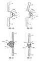
- FIG. 11Ais a side view illustrating a rod according to one embodiment.
- FIG. 11Bis a side view illustrating a rod according to one embodiment.
- FIG. 12is a side view illustrating a rod according to one embodiment.
- FIG. 13is a side view illustrating a rod according to one embodiment.
- FIG. 14is a side view illustrating a rod according to one embodiment.
- FIG. 15Ais a side view illustrating a rod in a first position according to one embodiment.
- FIG. 15Bis a side view illustrating a rod in a second position according to one embodiment.
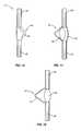
- FIG. 16is a side view illustrating a rod and a sleeve according to one embodiment.
- FIG. 17is a side view illustrating a rod according to one embodiment.
- FIG. 18is a side view illustrating a rod according to one embodiment.
- the present applicationis directed to vertebral rods and methods of supporting one or more vertebral members.
- the rodmay include upper and lower sections and an intermediate section.
- An elastic membermay be positioned at the intermediate section.
- the elastic membermay have a variety of orientations, sizes, shapes, densities, modulus of elasticity, and other material properties depending upon the desired displacement between the upper and lower sections.
- the elastic member and/or the intermediate sectionmay be elastically flexible to exert a stabilizing force during movement of the vertebral members.
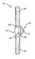
- FIG. 1Aillustrates a side perspective view
- FIG. 1Billustrates a front view of one embodiment of the rod 10 .
- the rod 10includes an upper section 20 and a lower section 30 separated by an intermediate section 40 .
- An elastic member 60may be positioned to work in combination with the intermediate section 40 to provide axial and lateral flexibility.
- the intermediate section 40 and elastic member 60provide variable resistance during movement of the vertebral members 100 .
- the resistancemay provide dynamic stabilization during a normal range of motion from the neutral position during flexion, extension, lateral bending, and rotation.
- the resistancemay be caused by placing the intermediate section 40 and elastic member 60 in compression or tension. Further, these elements may switch between compression and tension during movement of the vertebral members.
- the stiffness of the intermediate section 40 and elastic member 60may further limit the range of motion beyond a predetermined amount.
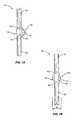
- FIG. 2illustrates one embodiment of two rods 10 attached to vertebral members 100 .
- the rods 10are positioned at a posterior side of the spine, on opposite sides of the spinous processes 101 .
- Rods 10may be attached to a spine at other locations, including lateral and anterior locations.
- Rods 10may also be attached at various sections of the spine, including the base of the skull and to vertebral members 100 in the cervical, thoracic, lumbar, and sacral regions.
- the illustration in FIG. 2is provided merely as a representative example of one embodiment. It is further well understood that a single rod 10 may be used for supporting the vertebral members 100 .
- the rods 10are secured to the vertebral members 100 by pedicle assemblies comprising a pedicle screw 12 including a receiver 14 and a retaining cap 13 .
- the outer surface of each rod 10is grasped, clamped, or otherwise secured within the receiver 14 and maintained in position by the retaining cap 13 .
- Other mechanisms for securing rods 10 to the vertebral members 100include hooks, cables, and other such devices.
- examples of other types of retaining hardwareinclude threaded caps, screws, and pins.
- Rods 10are also attached to plates in other configurations.
- the exemplary assemblies shown in FIG. 2are merely representative of one type of attachment mechanism.
- Upper and lower sections 20 , 30may have a variety of shapes, sizes, and physical properties. In one embodiment, the upper and lower sections 20 , 30 are substantially identical. In one embodiment, one or both of the sections 20 , 30 are substantially cylindrical including an extended length and a circular cross sectional shape. In one embodiment, one or both of the sections 20 , 30 are substantially rigid. One or both sections 20 , 30 may be substantially straight, include a continuous curve, or include one or more discrete curved sections.
- the intermediate section 40is positioned between the upper and lower sections 20 , 30 .
- the intermediate section 40 and upper and lower sections 20 , 30are constructed of a single piece including a folded or curved configuration.
- intermediate section 40is attached to the upper and lower sections 20 , 30 .
- FIG. 3illustrates one embodiment with the intermediate section 40 constructed of a separate member 41 that is attached to the sections 20 . 30 .
- Member 41is attached to the upper section 20 with one or more fasteners 16 .
- fasteners 16may include rivets, pins, screws, etc.
- member 41is attached to the lower section 30 in another manner, such as with adhesives, welding, brazing, etc.
- Intermediate section 40may be constructed from one or more members 41 .
- intermediate section 40is constructed from a single member 41 .
- the embodiment of FIG. 4illustrates the intermediate section 40 constructed of two separate members 41 a , 41 b .
- first member 41 ais connected with section 20
- second member 41 bis connected with section 30 .
- Members 41 a , 41 bare connected together in a manner as described above.
- Intermediate section 40may have a variety of widths.
- intermediate section 40has a width w that is greater than a width w′ of the upper and lower sections 20 , 30 .
- the width w of the intermediate section 40is less than or equal to the width w′ of the sections 20 , 30 .
- the width w of the intermediate section 40is up to four times the width of the sections 20 , 30 .
- the width w of the intermediate section 40may vary, as illustrated in the embodiment of FIG. 1B . In another embodiment, the width w is substantially constant.
- Intermediate section 40may also be positioned at a variety of locations relative to the sections 20 , 30 . In one embodiment as illustrated in FIG. 3 , intermediate section 40 is laterally offset from the sections 20 , 30 . In another embodiment as illustrated in FIG. 6A , intermediate section 40 is axially aligned with the sections 20 , 30 .
- intermediate section 40may comprise a member 18 including a first section 43 and a second section 44 .
- First and second sections 43 , 44may comprise the entirety of or a limited portion of the member 18 .
- intermediate section 40has substantially planar first and second sections 43 , 44 .
- intermediate section 40has a curved shape as illustrated in FIG. 5 .
- intermediate section 40has a combination of planar and curved shapes.
- intermediate section 40is constructed from a single member 18 .
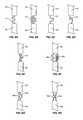
- FIGS. 6A and 6Billustrate embodiments with the intermediate section 40 comprised of a single member 18 including a curved shape.
- FIGS. 6C , 6 D, and 6 Eillustrate embodiments having an intermediate section 40 comprised of a single member 18 including planar and curved sections.
- Embodiments of the intermediate section 40may include multiple members 18 .
- FIG. 6Fillustrates an embodiment with a curved first member 18 a and a second member 18 b .
- FIGS. 6G and 6Hillustrate embodiments with first and second members 18 a , 18 b each including curved and planar sections.
- members 18may be constructed from a single piece, or multiple different pieces fastened together. Further, the multiple members 18 may be spaced apart, or in close proximity.
- Support members 18may also have an overlapping configuration. The overlap may be in a horizontal direction, vertical direction, or both.
- Member 18 of FIG. 6A and members 18 a and 18 b of FIG. 6Gillustrate embodiments having vertical overlap with multiple sections of each of these members overlapping vertical between the sections 20 , 30 .
- Member 18 of FIGS. 6B , 6 C, and 6 Ealso includes vertical overlap.
- Member 18 of FIG. 6Dillustrates an embodiment of horizontal overlap. Horizontal overlap occurs when a line perpendicular to the axis of sections 20 and 30 extends through the member at least twice. Some embodiments feature both horizontal and vertical overlap.
- Intermediate sections 40 comprising multiple members 18include horizontal overlap due to the construction.
- Each of the members 18 a , 18 bmay themselves include horizontal and/or vertical overlap.
- the intermediate section 40includes an open side 70 .
- the open side 70faces in anterior or posterior directions.
- an interior sectionis formed between the multiple members 18 that comprise the intermediate section 40 .
- the interior sectionmay have two sides enclosed by the members 18 .
- the lateral sides of the interior section 70are open.
- the interior section 70is completely enclosed.
- each rod 10includes two separate intermediate sections 40 .
- the intermediate sections 40may include the same or different sizes, shapes, and constructions.
- a middle section 42may be positioned along the length of the rod 10 between the intermediate sections 40 .
- middle section 42is constructed in a manner as described above for the upper and lower sections 20 , 30 .
- Upper and lower sections 20 , 30 , and the intermediate section 40may be constructed of a variety of materials including metals, polymers, ceramics, and combinations thereof.
- metalsinclude titanium, titanium alloys such as nickel-titanium, stainless steel, and cobalt chromium.
- polymersinclude silicone, silicone-polyurethane copolymer, polyolefin rubber, PEEK, PEEK-carbon composites, polyimide, polyetherimide, polyurethane, and combinations thereof.
- polyurethanesexamples include thermoplastic polyurethanes, aliphatic polyurethanes, segmented polyurethanes, hydrophilic polyurethanes, polyether-urethane, polycarbonate-urethane, silicone polyetherurethane, polyvinyl alcohol hydrogel, polyacrylamide hydrogel, and polyacrylic hydrogel.
- polyurethanesinclude thermoplastic polyurethanes, aliphatic polyurethanes, segmented polyurethanes, hydrophilic polyurethanes, polyether-urethane, polycarbonate-urethane, silicone polyetherurethane, polyvinyl alcohol hydrogel, polyacrylamide hydrogel, and polyacrylic hydrogel.
- ceramicsinclude calcium phosphate, hydroxyapatite, HAPCP, alumina, and zirconium.
- the intermediate section 40may provide resistance to movement of the upper and lower sections 20 , 30 . Movement of one or both of the sections 20 , 30 may cause deformation of the intermediate section 40 . In one embodiment, the resistance is substantially constant during movement of the sections 20 , 30 . In another embodiment, the resistance increases when one or both of the sections 20 , 30 move farther away from a first, neutral position.
- the shape of the intermediate section 40may also affect the resistance. In one embodiment, relative movement between the sections 20 , 30 in a first direction causes a first amount of resistance, and movement in a second, opposite direction causes a second, different amount of resistance. In one embodiment, the differences in resistance may be used to restriction motion of the vertebral members 100 in one direction (e.g., flexion) more than in a second direction (e.g., extension).
- An elastic member 60may be positioned within the intermediate section 40 and has a stiffness to provide resistance to movement of the sections 20 , 30 .
- the elastic member 60may share the load applied to the rod 10 and may prevent fatigue failure of the intermediate section 40 .
- the elastic member 60may impose a substantially linear or non-linear resistance to resist movement of the sections 20 , 30 .
- Elastic member 60may be constructed of a variety of different materials. Member 60 may be resilient and change shape during movement of the sections 20 , 30 . Examples of such materials include elastic or rubbery polymers, hydrogels or other hydrophilic polymers, or composites thereof. Particularly suitable elastomers include silicone, polyurethane, copolymers of silicone and polyurethane, polyolefins, such as polyisobutylene and polyisoprene, neoprene, nitrile, vulcanized rubber and combinations thereof.
- polyurethanesexamples include thermoplastic polyurethanes, aliphatic polyurethanes, segmented polyurethanes, hydrophilic polyurethanes, polyether-urethane, polycarbonate-urethane and silicone polyetherurethane.
- suitable hydrophilic polymersinclude polyvinyl alcohol hydrogel, polyacrylamide hydrogel, polyacrylic hydrogel, poly(N-vinyl-2-pyrrolidone hydrogel, polyhydroxyethyl methacrylate hydrogel, and naturally occurring materials such as collagen and polysaccharides, such as hyaluronic acid and cross-linked carboxyl-containing polysaccharides, and combinations thereof.
- elastic member 60is connected to the intermediate section 40 .
- the elastic member 60may be connected with mechanical fasteners such as screws, pins, rivets, tethers, sleeves, cables, etc.
- elastic member 60is connected with an adhesive.
- the intermediate section 40includes a roughened surface, ridges, teeth, etc. to maintain the position of the elastic member 60 .
- the elastic member 60has a shape that attaches to the intermediate section 40 .
- elastic member 60includes a dovetail recess that attaches with an extension that extends from the intermediate section 40 .
- elastic member 60is connected to both the first and second sections 43 , 44 of the intermediate section 40 .
- the elastic member 60provides resistance to both inward and outward movement that may occur during flexion, extension, lateral bending, and rotation.
- elastic member 60is compressed and provides a resistance to the inward movement.
- the elastic member 60is placed in tension to provide resistance.
- the elastic member 60is placed in compression during extension of the vertebral members and placed in tension during flexion.
- the elastic member 60provides resistance to inward movement.
- the elastic member 60may not be placed in tension during outward movement of the sections 20 , 30 and the resistance to this movement is limited to the intermediate section 40 .
- elastic member 60is constructed from a single member as illustrated in FIGS. 7A-7D .
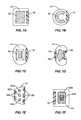
- FIG. 7Aillustrates one embodiment having an elastic member 60 with a substantially rectangular shape.
- FIG. 7Billustrates a substantially C-shaped elastic member 60 with the base facing away from the support member 18 .
- FIG. 7Cillustrates an elastic member 60 having a rectangular first surface that contacts the second section 44 and four planar sidewalls that taper upwards.
- FIG. 7Dillustrates an embodiment having an irregular, non-symmetrical shape.
- Elastic member 60may further include two or more separate members.
- the separate membersmay have the same construction, or may be constructed of different materials each having a different stiffness.
- FIG. 7Eillustrates an embodiment having three separate elastic members 60 a , 60 b , 60 c .
- Each elastic member 60 a , 60 b , 60 cis independent and has a substantially circular shape that may be cylindrical, spherical, or conical.
- FIG. 7Fillustrates an embodiment having a first elastic member 60 a that extends around a second elastic member 60 b .
- elastic members 60 a , 60 bare connected together.
- the elastic member 60may have a variety of heights H.
- the height His sized for the member 60 to extend between and contact both sections 43 , 44 .
- the height Hmay be substantially the same throughout the elastic member 60 .
- the height Hmay vary along the elastic member 60 .
- FIG. 8includes elastic member 60 having a height H that decreases away from the support member 18
- FIG. 9includes the elastic member 60 having a height H the increases away from the support member 18 .
- the device 10may provide a variable resistance to deformation.
- the variable resistancemay cause less resistance to initial amounts of vertebral movement, but apply greater forces to reduce larger vertebral movements.
- the device 10may be designed to provide little resistance during an initial amount of movement of the sections 20 , 30 . Larger amounts of resistance may be applied to the vertebral members when the sections 20 , 30 move beyond the initial amount.
- the stiffness of the elastic member 60 and intermediate section 40increases with additional amounts of movement. The amount of resistance applied by each member increases the further they move away from the original, first position.
- Variable resistance to inward movementmay also result from the height of the elastic member 60 .
- the height His less than the height of the opening 70 (i.e., the member 60 does not contact both sections 43 , 44 ).
- the resistance to the initial movement of the sections 20 , 30is isolated to the intermediate section 40 .
- the elastic member 60does not affect the stiffness until it is contacted by two sections 43 , 44 of the intermediate section 40 and begins to elastically deform.
- deformationis limited to the intermediate section 40 during an amount of initial section movement. Movement beyond this initial amount causes the sections 43 , 44 to begin deforming the elastic member 60 in addition to continued deformation of the intermediate section 40 resulting in greater stiffness of the device and more resistance to additional movement.
- the shape and size of the elastic member 60may further cause variable resistance to deformation. Greater amounts of contact between the sections 43 , 44 and the elastic member 60 may result in greater amounts of resistance.
- the peaked shapes of the elastic members 60provides less resistance during initial amounts of inward movement of the sections 43 , 44 . Additional inward movement of the sections 43 , 44 results in deformation of larger amounts of the elastic member 60 resulting in greater resistance.
- FIG. 10illustrates an embodiment having two intermediate sections 40 .
- a first intermediate section 40includes two separate elastic members 60 a and 60 b .
- the inner elastic member 60 ais initially contacted thus causing a first amount of resistance.
- the second elastic member 60 bis not contacted by section 43 a until the member 60 a is compressed beyond a predetermined amount. This compression then causes the elastic member 60 b to deform resulting in additional amounts of resistance.
- the second intermediate 40 sectionincludes a single elastic member constructed of first and second materials 60 c , 60 d having different stiffnesses.
- Initial compression of the sections 43 b , 44 bcauses deformation of the first material 60 c resulting in a first resistance.
- Additional compressioncauses deformation of the first and second materials 60 c , 60 d which together provide additional resistance.
- FIGS. 11A and 11Billustrate another embodiment having first and second members 60 a , 60 b positioned between the sections 43 , 44 .
- member 60 bhas a greater length and is in a slackened configuration when the rod 10 is in a neutral orientation with no external forces.
- An initial outward movement of the sections 43 , 44is resisted initially by the first member 60 a and the intermediate section 40 .
- member 60 bis pulled tight. Movement beyond this amount causes the member 60 b to be stretched and further movement is opposed by the combination of the first and second members 60 a , 60 b and the intermediate section 40 .
- Members 60 a , 60 bmay be constructed of the same or different materials.
- member 60 bis constructed of an inelastic material and acts as a limiter to control the extent of outward movement.
- the sections 43 , 44are moved apart an amount until the member 60 b is pulled tight.
- the inelastic nature of the member 60 bthen prevents further outward movement of the sections 43 , 44 beyond this amount.
- member 60 bimmediately restricts further motion once it is pulled tight, such as occurs with a metallic member.
- member 60 bprovides for a small amount of additional outward movement after being pulled tight prior to stopping further movement.
- An exampleincludes a woven fabric that expands a slight amount after the member 60 b has been pulled tight.
- the limiter member 60 b as illustrated in the embodiments of FIGS. 11A and 11Bmay be constructed of a variety of materials including metals, polymers, and ceramics.
- metalsmay include titanium and stainless steel.
- polymersmay include fibers and textile-based products that are woven or braided.
- An example of a ceramicis a carbon fiber in a braided configuration.
- Elastic member 60may fill varying amounts of the space between the sections 20 , 30 . In one embodiment, member 60 fills a limited amount of the intermediate section 40 . In another embodiment as illustrated in FIG. 12 , elastic member 60 substantially fills the entirety of the interior section 70 . In this embodiment, voids 78 are positioned within the elastic member 60 . In one embodiment, voids 78 include a specific shape and size to control the supporting abilities of the elastic member 60 . Voids 78 may be substantially free of material, or may be filled with a material that is different than that of the elastic member 60 . As illustrated in FIG. 12 , voids 78 may be positioned within the interior of the elastic member 60 , or may be positioned along one edge as illustrated in FIG. 13 .
- a limitermay prevent movement of the sections 20 , 30 beyond a predetermined amount.
- FIG. 14illustrates one embodiment having a rigid limiting member 79 positioned within the intermediate section 40 between the sections 43 , 44 . Movement of one or both sections 20 , 30 may cause inward movement of the sections 43 , 44 and cause deformation of the elastic member 60 . At a predetermined amount of movement, section 43 contacts a top edge of limiting member 79 that prevents further inward movement. Limiting member 79 may have a variety of different shapes and orientations.
- FIGS. 15A and 15BAnother limiting embodiment is illustrated in FIGS. 15A and 15B .
- Arms 92 , 93are positioned opposite from sections 43 and 44 .
- Arms 92 , 93include edges that are spaced apart forming a gap 49 in a first position such as in a neutral state as illustrated in FIG. 15A . This allows for a limited amount of inward movement of the sections 43 , 44 during vertebral movement. At a predetermined amount of inward movement, edges contact together as illustrated in FIG. 15B and further inward movement is prevented.
- a sleeve 85extends around the intermediate section 40 .
- sleeve 85functions to maintain the elastic material 60 within the intermediate section 40 .
- Sleeve 85may further provide resistance to movement of the sections 20 , 30 .
- sleeve 85applies resistance to outward movement of the intermediate section 40 .
- Sleeve 85may be constructed from materials that are elastic, semi-elastic, or inelastic.
- Sleeve 85may be solid, such as constructed from silicone, may be braided or woven, such as a polyester braid or weave, or may be a combination of different materials and constructions.
- Tethers 150may also be used to provide additional resistance to device 10 .
- tether 150extends across the open side 70 and is attached to the first and second sections 20 , 30 . Tether 150 provides resistance during outward movement of the sections 20 , 30 .
- multiple tethers 150extend across the open side 70 .
- Tethers 150may have a variety of widths and shapes depending upon the context of use.
- tether 150is constructed of an elastic material that stretches upon movement of the vertebral members 100 .
- tether 150is constructed of an inelastic material to prevent movement beyond a predetermined amount.
- one or more tethers 150are connected to the elastic member 60 .
- the tether 150is completely contained within the elastic member 60 . In one embodiment, tether 150 is positioned completely or in part on the exterior surface of the elastic member 60 . In another embodiment, tether 150 extends outward from the elastic member 60 . The tether or tethers 150 connected to the elastic member 60 may provide additional resistance during vertebral movement.
- FIG. 18illustrates another embodiment with the elastic member 60 contacting the upper and lower sections 20 , 30 .
- elastic member 60is spaced away from the member 18 .
- elastic member 60is also in contact with the member 18 .
- the elastic member 60When the elastic member 60 is formed from an elastic material, such as a hydrogel, or other similar hydrophilic material, it may deliver desired pharmacological agents. In one embodiment, the pharmacological agents are delivered during deformation of the elastic member 60 .
- the pharmacological agentmay be a one used for treating various spinal conditions, including degenerative disc disease, spinal arthritis, spinal infection, spinal tumor and osteoporosis. Such agents include antibiotics, analgesics, anti-inflammatory drugs, including steroids, and combinations thereof. Other such agents are well known to the skilled artisan. These agents are also used in therapeutically effective amounts. Such amounts may be determined by the skilled artisan depending on the specific case.
- the elastic member 60is attached to the intermediate member 40 to move between positions of tension and compression. During a first motion of the vertebral members 100 , the elastic member 60 is placed in compression to provide resistance to the movement. During a second motion of the vertebral members 100 , the elastic member 60 is placed in tension to provide resistance to the motion. In one embodiment, the intermediate section 40 is in sequence placed in compression and tension during vertebral movement.
Landscapes
- Health & Medical Sciences (AREA)
- Orthopedic Medicine & Surgery (AREA)
- Life Sciences & Earth Sciences (AREA)
- Neurology (AREA)
- Surgery (AREA)
- Heart & Thoracic Surgery (AREA)
- General Health & Medical Sciences (AREA)
- Biomedical Technology (AREA)
- Nuclear Medicine, Radiotherapy & Molecular Imaging (AREA)
- Medical Informatics (AREA)
- Molecular Biology (AREA)
- Animal Behavior & Ethology (AREA)
- Engineering & Computer Science (AREA)
- Public Health (AREA)
- Veterinary Medicine (AREA)
- Prostheses (AREA)
- Superconductors And Manufacturing Methods Therefor (AREA)
- Surgical Instruments (AREA)
- Reciprocating, Oscillating Or Vibrating Motors (AREA)
Abstract
Description
Vertebral rods are often used in the surgical treatment of spinal disorders such as degenerative disc disease, disc herniations, scoliosis or other curvature abnormalities, and fractures. Different types of surgical treatments are used. In some cases, spinal fusion is indicated to inhibit relative motion between vertebral members. In other cases, dynamic implants are used to preserve motion between vertebral members. For either type of surgical treatment, one or more rods may be attached to the exterior of two or more vertebral members, whether it is at a posterior, anterior, or lateral side of the vertebral members. In other embodiments, rods are attached to the vertebral members without the use of dynamic implants or spinal fusion.
Rods may redirect stresses over a wider area away from a damaged or defective region and restore the spine to its proper alignment. Rods may also increase loading on interbody constructs, decrease stress transfer to adjacent vertebral members while bone-graft healing takes place, and generally support the vertebral members.
The present application is directed to vertebral rods and methods of use. In one embodiment, the rod includes upper and lower sections that are separated by an intermediate section. The intermediate section may include one or more members, and may have a variety of configurations. An elastic member may be positioned within the intermediate section. The intermediate section and the elastic member may provide for variable resistance during movement of the upper and lower sections. In one embodiment, the resistance increases the further away the upper and lower sections move from a first orientation. In one embodiment, the extent of movement of the upper and lower sections is limited.
The present application is directed to vertebral rods and methods of supporting one or more vertebral members. The rod may include upper and lower sections and an intermediate section. An elastic member may be positioned at the intermediate section. The elastic member may have a variety of orientations, sizes, shapes, densities, modulus of elasticity, and other material properties depending upon the desired displacement between the upper and lower sections. The elastic member and/or the intermediate section may be elastically flexible to exert a stabilizing force during movement of the vertebral members.
In one embodiment, theintermediate section 40 andelastic member 60 provide variable resistance during movement of thevertebral members 100. The resistance may provide dynamic stabilization during a normal range of motion from the neutral position during flexion, extension, lateral bending, and rotation. The resistance may be caused by placing theintermediate section 40 andelastic member 60 in compression or tension. Further, these elements may switch between compression and tension during movement of the vertebral members. The stiffness of theintermediate section 40 andelastic member 60 may further limit the range of motion beyond a predetermined amount.
In the embodiment ofFIG. 2 , therods 10 are secured to thevertebral members 100 by pedicle assemblies comprising apedicle screw 12 including areceiver 14 and a retainingcap 13. The outer surface of eachrod 10 is grasped, clamped, or otherwise secured within thereceiver 14 and maintained in position by the retainingcap 13. Other mechanisms for securingrods 10 to thevertebral members 100 include hooks, cables, and other such devices. Further, examples of other types of retaining hardware include threaded caps, screws, and pins.Rods 10 are also attached to plates in other configurations. Thus, the exemplary assemblies shown inFIG. 2 are merely representative of one type of attachment mechanism.
Upper andlower sections lower sections sections sections sections
Theintermediate section 40 is positioned between the upper andlower sections intermediate section 40 and upper andlower sections intermediate section 40 is attached to the upper andlower sections FIG. 3 illustrates one embodiment with theintermediate section 40 constructed of aseparate member 41 that is attached to thesections 20.30.Member 41 is attached to theupper section 20 with one ormore fasteners 16. Embodiments offasteners 16 may include rivets, pins, screws, etc. In the embodiment ofFIG. 3 ,member 41 is attached to thelower section 30 in another manner, such as with adhesives, welding, brazing, etc.
In one embodiment,intermediate section 40 may comprise amember 18 including afirst section 43 and asecond section 44. First andsecond sections member 18. In one embodiment as illustrated inFIG. 4 ,intermediate section 40 has substantially planar first andsecond sections intermediate section 40 has a curved shape as illustrated inFIG. 5 . In various other embodiments such as illustrated inFIG. 3 ,intermediate section 40 has a combination of planar and curved shapes.
In some embodiments,intermediate section 40 is constructed from asingle member 18.FIGS. 6A and 6B illustrate embodiments with theintermediate section 40 comprised of asingle member 18 including a curved shape.FIGS. 6C ,6D, and6E illustrate embodiments having anintermediate section 40 comprised of asingle member 18 including planar and curved sections.
Embodiments of theintermediate section 40 may includemultiple members 18.FIG. 6F illustrates an embodiment with a curvedfirst member 18aand asecond member 18b.FIGS. 6G and 6H illustrate embodiments with first andsecond members multiple members 18,members 18 may be constructed from a single piece, or multiple different pieces fastened together. Further, themultiple members 18 may be spaced apart, or in close proximity.
In one embodiment as illustrated inFIG. 1A , theintermediate section 40 includes anopen side 70. In different embodiments, theopen side 70 faces in anterior or posterior directions. In one embodiment, an interior section is formed between themultiple members 18 that comprise theintermediate section 40. The interior section may have two sides enclosed by themembers 18. In one embodiment, the lateral sides of theinterior section 70 are open. In another embodiment, theinterior section 70 is completely enclosed.
Multipleintermediate sections 40 may be positioned along the length of therod 10. In one embodiment as illustrated inFIG. 2 , eachrod 10 includes two separateintermediate sections 40. Theintermediate sections 40 may include the same or different sizes, shapes, and constructions. Amiddle section 42 may be positioned along the length of therod 10 between theintermediate sections 40. In one embodiment,middle section 42 is constructed in a manner as described above for the upper andlower sections
Upper andlower sections intermediate section 40 may be constructed of a variety of materials including metals, polymers, ceramics, and combinations thereof. Examples of metals include titanium, titanium alloys such as nickel-titanium, stainless steel, and cobalt chromium. Examples of polymers include silicone, silicone-polyurethane copolymer, polyolefin rubber, PEEK, PEEK-carbon composites, polyimide, polyetherimide, polyurethane, and combinations thereof. Examples of polyurethanes include thermoplastic polyurethanes, aliphatic polyurethanes, segmented polyurethanes, hydrophilic polyurethanes, polyether-urethane, polycarbonate-urethane, silicone polyetherurethane, polyvinyl alcohol hydrogel, polyacrylamide hydrogel, and polyacrylic hydrogel. Examples of ceramics include calcium phosphate, hydroxyapatite, HAPCP, alumina, and zirconium.
Theintermediate section 40 may provide resistance to movement of the upper andlower sections sections intermediate section 40. In one embodiment, the resistance is substantially constant during movement of thesections sections intermediate section 40 may also affect the resistance. In one embodiment, relative movement between thesections vertebral members 100 in one direction (e.g., flexion) more than in a second direction (e.g., extension).
Anelastic member 60 may be positioned within theintermediate section 40 and has a stiffness to provide resistance to movement of thesections elastic member 60 may share the load applied to therod 10 and may prevent fatigue failure of theintermediate section 40. Theelastic member 60 may impose a substantially linear or non-linear resistance to resist movement of thesections
In one embodiment,elastic member 60 is connected to theintermediate section 40. Theelastic member 60 may be connected with mechanical fasteners such as screws, pins, rivets, tethers, sleeves, cables, etc. In another embodiment,elastic member 60 is connected with an adhesive. In one embodiment, theintermediate section 40 includes a roughened surface, ridges, teeth, etc. to maintain the position of theelastic member 60. In one embodiment, theelastic member 60 has a shape that attaches to theintermediate section 40. In a specific embodiment,elastic member 60 includes a dovetail recess that attaches with an extension that extends from theintermediate section 40.
In one embodiment,elastic member 60 is connected to both the first andsecond sections intermediate section 40. When connected to bothsections elastic member 60 provides resistance to both inward and outward movement that may occur during flexion, extension, lateral bending, and rotation. During inward movement of thesections elastic member 60 is compressed and provides a resistance to the inward movement. During outward movement of thesections elastic member 60 is placed in tension to provide resistance. In one embodiment, theelastic member 60 is placed in compression during extension of the vertebral members and placed in tension during flexion.
In one embodiment with theelastic member 60 connected to one of the first andsecond sections elastic member 60 provides resistance to inward movement. However, theelastic member 60 may not be placed in tension during outward movement of thesections intermediate section 40.
In various embodiments,elastic member 60 is constructed from a single member as illustrated inFIGS. 7A-7D .FIG. 7A illustrates one embodiment having anelastic member 60 with a substantially rectangular shape.FIG. 7B illustrates a substantially C-shapedelastic member 60 with the base facing away from thesupport member 18.FIG. 7C illustrates anelastic member 60 having a rectangular first surface that contacts thesecond section 44 and four planar sidewalls that taper upwards.FIG. 7D illustrates an embodiment having an irregular, non-symmetrical shape.
In a neutral condition with no external forces on therod 10, theelastic member 60 may have a variety of heights H. In one embodiment, the height H is sized for themember 60 to extend between and contact bothsections elastic member 60. In other embodiments as illustrated inFIGS. 8 and 9 , the height H may vary along theelastic member 60.FIG. 8 includeselastic member 60 having a height H that decreases away from thesupport member 18, andFIG. 9 includes theelastic member 60 having a height H the increases away from thesupport member 18.
Thedevice 10 may provide a variable resistance to deformation. The variable resistance may cause less resistance to initial amounts of vertebral movement, but apply greater forces to reduce larger vertebral movements. By way of example, thedevice 10 may be designed to provide little resistance during an initial amount of movement of thesections sections elastic member 60 andintermediate section 40 increases with additional amounts of movement. The amount of resistance applied by each member increases the further they move away from the original, first position.
Variable resistance to inward movement may also result from the height of theelastic member 60. In one embodiment, the height H is less than the height of the opening70 (i.e., themember 60 does not contact bothsections 43,44). The resistance to the initial movement of thesections intermediate section 40. Theelastic member 60 does not affect the stiffness until it is contacted by twosections intermediate section 40 and begins to elastically deform. In one embodiment, deformation is limited to theintermediate section 40 during an amount of initial section movement. Movement beyond this initial amount causes thesections elastic member 60 in addition to continued deformation of theintermediate section 40 resulting in greater stiffness of the device and more resistance to additional movement.
The shape and size of theelastic member 60 may further cause variable resistance to deformation. Greater amounts of contact between thesections elastic member 60 may result in greater amounts of resistance. By way of example using the embodiments ofFIGS. 8 and 9 , the peaked shapes of theelastic members 60 provides less resistance during initial amounts of inward movement of thesections sections elastic member 60 resulting in greater resistance.
Variable resistance may also be provided by multiple elastic elements.FIG. 10 illustrates an embodiment having twointermediate sections 40. A firstintermediate section 40 includes two separateelastic members sections elastic member 60ais initially contacted thus causing a first amount of resistance. The secondelastic member 60bis not contacted bysection 43auntil themember 60ais compressed beyond a predetermined amount. This compression then causes theelastic member 60bto deform resulting in additional amounts of resistance. The second intermediate40 section includes a single elastic member constructed of first andsecond materials 60c,60dhaving different stiffnesses. Initial compression of thesections second materials 60c,60dwhich together provide additional resistance.
In one embodiment,member 60bis constructed of an inelastic material and acts as a limiter to control the extent of outward movement. In this embodiment, thesections member 60bis pulled tight. The inelastic nature of themember 60bthen prevents further outward movement of thesections member 60bimmediately restricts further motion once it is pulled tight, such as occurs with a metallic member. In another embodiment,member 60bprovides for a small amount of additional outward movement after being pulled tight prior to stopping further movement. An example includes a woven fabric that expands a slight amount after themember 60bhas been pulled tight.
Thelimiter member 60bas illustrated in the embodiments ofFIGS. 11A and 11B may be constructed of a variety of materials including metals, polymers, and ceramics. Examples of metals may include titanium and stainless steel. Examples of polymers may include fibers and textile-based products that are woven or braided. An example of a ceramic is a carbon fiber in a braided configuration.
A limiter may prevent movement of thesections FIG. 14 illustrates one embodiment having a rigid limitingmember 79 positioned within theintermediate section 40 between thesections sections sections elastic member 60. At a predetermined amount of movement,section 43 contacts a top edge of limitingmember 79 that prevents further inward movement. Limitingmember 79 may have a variety of different shapes and orientations.
Another limiting embodiment is illustrated inFIGS. 15A and 15B .Arms sections Arms gap 49 in a first position such as in a neutral state as illustrated inFIG. 15A . This allows for a limited amount of inward movement of thesections FIG. 15B and further inward movement is prevented.
In one embodiment as illustrated inFIG. 16 , asleeve 85 extends around theintermediate section 40. In one embodiment,sleeve 85 functions to maintain theelastic material 60 within theintermediate section 40.Sleeve 85 may further provide resistance to movement of thesections sleeve 85 applies resistance to outward movement of theintermediate section 40.Sleeve 85 may be constructed from materials that are elastic, semi-elastic, or inelastic.Sleeve 85 may be solid, such as constructed from silicone, may be braided or woven, such as a polyester braid or weave, or may be a combination of different materials and constructions.
When theelastic member 60 is formed from an elastic material, such as a hydrogel, or other similar hydrophilic material, it may deliver desired pharmacological agents. In one embodiment, the pharmacological agents are delivered during deformation of theelastic member 60. The pharmacological agent may be a one used for treating various spinal conditions, including degenerative disc disease, spinal arthritis, spinal infection, spinal tumor and osteoporosis. Such agents include antibiotics, analgesics, anti-inflammatory drugs, including steroids, and combinations thereof. Other such agents are well known to the skilled artisan. These agents are also used in therapeutically effective amounts. Such amounts may be determined by the skilled artisan depending on the specific case.
In one embodiment, theelastic member 60 is attached to theintermediate member 40 to move between positions of tension and compression. During a first motion of thevertebral members 100, theelastic member 60 is placed in compression to provide resistance to the movement. During a second motion of thevertebral members 100, theelastic member 60 is placed in tension to provide resistance to the motion. In one embodiment, theintermediate section 40 is in sequence placed in compression and tension during vertebral movement.
Spatially relative terms such as “under”, “below”, “lower”, “over”, “upper”, and the like, are used for ease of description to explain the positioning of one element relative to a second element. These terms are intended to encompass different orientations of the device in addition to different orientations than those depicted in the figures. Further, terms such as “first”, “second”, and the like, are also used to describe various elements, regions, sections, etc and are also not intended to be limiting. Like terms refer to like elements throughout the description.
As used herein, the terms “having”, “containing”, “including”, “comprising” and the like are open ended terms that indicate the presence of stated elements or features, but do not preclude additional elements or features. The articles “a”, “an” and “the” are intended to include the plural as well as the singular, unless the context clearly indicates otherwise.
The present invention may be carried out in other specific ways than those herein set forth without departing from the scope and essential characteristics of the invention. The present embodiments are, therefore, to be considered in all respects as illustrative and not restrictive, and all changes coming within the meaning and equivalency range of the appended claims are intended to be embraced therein.
Claims (6)
1. A vertebral rod comprising:
a first elongated rod section;
a second elongated rod section aligned along an axis with the first section;
an intermediate section positioned between the first and second sections, the intermediate section comprising a member with a turn and an upper section and a lower section, the intermediate section being open between the first and second sections opposite from the turn, each of the upper and lower sections including inner surfaces that intersect at the turn and overlap to form an interior portion;
an elastic member positioned in the interior portion of the intermediate section directly between the first and second sections along the axis; the elastic member distinct from the first, second, and intermediate sections and differing in material composition therefrom; the elastic member connected to the inner surfaces of both the upper and lower sections;
the intermediate section and elastic member configured to provide variable resistance to movement of the first and second sections, the elastic member being in compression during a first type of movement of the first and second sections and being in tension during a second type of movement;
wherein the elastic member is configured such that the axis exits the first section, enters the elastic member, passes through the elastic member, exits the elastic member, and enters the second section all without exiting the elastic member more than once.
2. The rod ofclaim 1 wherein the elastic member is adhesively secured to the intermediate section.
3. The rod ofclaim 1 wherein the elastic member engages the inner surfaces of the upper and lower sections of the intermediate section when the rod is in a neutral position free from applied loads acting thereon.
4. The rod ofclaim 1 wherein the elastic member is an elastically deformable block having external surfaces facing the first and second sections.
5. A vertebral rod assembly comprising:
a first elongated rod section;
a second elongated rod section spaced from the first rod section;
the first and second rod sections extending along a common centerline;
an intermediate section monolithically formed with the first and second rod sections and bridging therebetween; the intermediate section being offset from the centerline and convexly curved toward the centerline to form a pocket;
the first rod section having a first endface proximate the intermediate section;
the second rod section having a second endface proximate the intermediate section; the first and second endfaces generally facing toward each other;
an elastic bumper disposed in the pocket such that the centerline passes therethrough; the elastic bumper, with the rod assembly in a neutral position free from applied loads acting thereon, abutting the first endface along the centerline, the second endface along the centerline, and the intermediate section;
the elastic bumper formed of a different material than the first rod section, the second rod section, and the intermediate section;
the intermediate section and elastic bumper configured to provide variable resistance to movement of the first and second sections, the elastic bumper being in compression during a first type of movement of the first and second sections and being in tension during a second type of movement.
6. The vertebral rod assembly ofclaim 5 wherein the intermediate section has an interior surface bounding the pocket, the interior surface extending substantially all the way from the first rod section to the second rod section; wherein the elastic bumper, with the rod assembly in a neutral position free from applied loads acting thereon, abuts substantially all of the interior surface of the intermediate section.
Priority Applications (12)
| Application Number | Priority Date | Filing Date | Title |
|---|---|---|---|
| US11/340,973US7815663B2 (en) | 2006-01-27 | 2006-01-27 | Vertebral rods and methods of use |
| PCT/US2007/060966WO2007090015A1 (en) | 2006-01-27 | 2007-01-24 | Vertebral rods and methods of use |
| ES07710289TES2358906T3 (en) | 2006-01-27 | 2007-01-24 | VERTEBRAL RODS. |
| EP07710289AEP1983913B1 (en) | 2006-01-27 | 2007-01-24 | Vertebral rods |
| DK07710289.5TDK1983913T3 (en) | 2006-01-27 | 2007-01-24 | Vertebral bars and their use |
| CNA2007800073674ACN101394803A (en) | 2006-01-27 | 2007-01-24 | Vertebral rods and methods of use |
| AT07710289TATE499057T1 (en) | 2006-01-27 | 2007-01-24 | SWIRLING RODS |
| AU2007211118AAU2007211118B2 (en) | 2006-01-27 | 2007-01-24 | Vertebral rods and methods of use |
| DE602007012660TDE602007012660D1 (en) | 2006-01-27 | 2007-01-24 | EDDY RODS |
| EP10175299AEP2298200A1 (en) | 2006-01-27 | 2007-01-24 | Vertebral rod |
| US12/896,966US8414619B2 (en) | 2006-01-27 | 2010-10-04 | Vertebral rods and methods of use |
| US13/850,396US9144439B2 (en) | 2006-01-27 | 2013-03-26 | Vertebral rods and methods of use |
Applications Claiming Priority (1)
| Application Number | Priority Date | Filing Date | Title |
|---|---|---|---|
| US11/340,973US7815663B2 (en) | 2006-01-27 | 2006-01-27 | Vertebral rods and methods of use |
Related Child Applications (1)
| Application Number | Title | Priority Date | Filing Date |
|---|---|---|---|
| US12/896,966DivisionUS8414619B2 (en) | 2006-01-27 | 2010-10-04 | Vertebral rods and methods of use |
Publications (2)
| Publication Number | Publication Date |
|---|---|
| US20070191832A1 US20070191832A1 (en) | 2007-08-16 |
| US7815663B2true US7815663B2 (en) | 2010-10-19 |
Family
ID=38057448
Family Applications (3)
| Application Number | Title | Priority Date | Filing Date |
|---|---|---|---|
| US11/340,973Active2027-08-25US7815663B2 (en) | 2006-01-27 | 2006-01-27 | Vertebral rods and methods of use |
| US12/896,966Active2026-08-12US8414619B2 (en) | 2006-01-27 | 2010-10-04 | Vertebral rods and methods of use |
| US13/850,396Active2026-06-18US9144439B2 (en) | 2006-01-27 | 2013-03-26 | Vertebral rods and methods of use |
Family Applications After (2)
| Application Number | Title | Priority Date | Filing Date |
|---|---|---|---|
| US12/896,966Active2026-08-12US8414619B2 (en) | 2006-01-27 | 2010-10-04 | Vertebral rods and methods of use |
| US13/850,396Active2026-06-18US9144439B2 (en) | 2006-01-27 | 2013-03-26 | Vertebral rods and methods of use |
Country Status (9)
| Country | Link |
|---|---|
| US (3) | US7815663B2 (en) |
| EP (2) | EP1983913B1 (en) |
| CN (1) | CN101394803A (en) |
| AT (1) | ATE499057T1 (en) |
| AU (1) | AU2007211118B2 (en) |
| DE (1) | DE602007012660D1 (en) |
| DK (1) | DK1983913T3 (en) |
| ES (1) | ES2358906T3 (en) |
| WO (1) | WO2007090015A1 (en) |
Cited By (29)
| Publication number | Priority date | Publication date | Assignee | Title |
|---|---|---|---|---|
| US20080234739A1 (en)* | 2007-03-13 | 2008-09-25 | Zimmer Spine, Inc. | Dynamic spinal stabilization system and method of using the same |
| US20100318130A1 (en)* | 2007-12-15 | 2010-12-16 | Parlato Brian D | Flexible rod assembly for spinal fixation |
| US20110022092A1 (en)* | 2006-01-27 | 2011-01-27 | Warsaw Orthopedic, Inc. | Vertebral rods and methods of use |
| US20110071570A1 (en)* | 2009-09-24 | 2011-03-24 | Warsaw Orthopedic, Inc. | Composite vertebral rod system and methods of use |
| US8353932B2 (en) | 2005-09-30 | 2013-01-15 | Jackson Roger P | Polyaxial bone anchor assembly with one-piece closure, pressure insert and plastic elongate member |
| US8394133B2 (en) | 2004-02-27 | 2013-03-12 | Roger P. Jackson | Dynamic fixation assemblies with inner core and outer coil-like member |
| US8475498B2 (en) | 2007-01-18 | 2013-07-02 | Roger P. Jackson | Dynamic stabilization connecting member with cord connection |
| US8591560B2 (en) | 2005-09-30 | 2013-11-26 | Roger P. Jackson | Dynamic stabilization connecting member with elastic core and outer sleeve |
| US8613760B2 (en) | 2005-09-30 | 2013-12-24 | Roger P. Jackson | Dynamic stabilization connecting member with slitted core and outer sleeve |
| US8663284B2 (en) | 2010-09-20 | 2014-03-04 | Aesculap Ag | Spinal column stabilization system, connecting element for a spinal column stabilization system and method of manufacturing such a connecting element |
| US20140309741A1 (en)* | 2013-03-15 | 2014-10-16 | Paradigm Spine, Llc | Modular, customizable spine stabilization system |
| US8979904B2 (en) | 2007-05-01 | 2015-03-17 | Roger P Jackson | Connecting member with tensioned cord, low profile rigid sleeve and spacer with torsion control |
| US20150173799A1 (en)* | 2012-07-05 | 2015-06-25 | Spinesave Ag | Elastic rod having different degrees of stiffness for the surgical treatment of the spine |
| US9216039B2 (en) | 2004-02-27 | 2015-12-22 | Roger P. Jackson | Dynamic spinal stabilization assemblies, tool set and method |
| US9216041B2 (en) | 2009-06-15 | 2015-12-22 | Roger P. Jackson | Spinal connecting members with tensioned cords and rigid sleeves for engaging compression inserts |
| US9232964B2 (en) | 2010-08-26 | 2016-01-12 | Spinesave Ag | Spinal implant set for the dynamic stabilization of the spine |
| US20160030194A1 (en)* | 2013-03-15 | 2016-02-04 | Revivo Medical, Llc | Intervertebral cage and method of treating vertebrae with an intervertebral cage |
| US9451989B2 (en) | 2007-01-18 | 2016-09-27 | Roger P Jackson | Dynamic stabilization members with elastic and inelastic sections |
| US9743957B2 (en) | 2004-11-10 | 2017-08-29 | Roger P. Jackson | Polyaxial bone screw with shank articulation pressure insert and method |
| US10039578B2 (en) | 2003-12-16 | 2018-08-07 | DePuy Synthes Products, Inc. | Methods and devices for minimally invasive spinal fixation element placement |
| US10258382B2 (en) | 2007-01-18 | 2019-04-16 | Roger P. Jackson | Rod-cord dynamic connection assemblies with slidable bone anchor attachment members along the cord |
| US10383660B2 (en) | 2007-05-01 | 2019-08-20 | Roger P. Jackson | Soft stabilization assemblies with pretensioned cords |
| US10456172B2 (en) | 2016-02-12 | 2019-10-29 | Nuvasive, Inc. | Magnetically actuateable rod insertion for minimally invasive surgery |
| US10729469B2 (en) | 2006-01-09 | 2020-08-04 | Roger P. Jackson | Flexible spinal stabilization assembly with spacer having off-axis core member |
| US10758274B1 (en) | 2014-05-02 | 2020-09-01 | Nuvasive, Inc. | Spinal fixation constructs and related methods |
| US11291478B2 (en) | 2016-02-12 | 2022-04-05 | Nuvasive, Inc. | Post-operatively adjustable spinal fixation devices |
| US11331199B2 (en)* | 2019-04-29 | 2022-05-17 | Aurora Spine, Inc. | Spinal implant for motion preservation or fusion |
| US11583318B2 (en) | 2018-12-21 | 2023-02-21 | Paradigm Spine, Llc | Modular spine stabilization system and associated instruments |
| US20230085446A1 (en)* | 2007-06-22 | 2023-03-16 | Empirical Spine, Inc, | Methods and systems for increasing the bending stiffness of a spinal segment with elongation limit |
Families Citing this family (74)
| Publication number | Priority date | Publication date | Assignee | Title |
|---|---|---|---|---|
| FR2812185B1 (en) | 2000-07-25 | 2003-02-28 | Spine Next Sa | SEMI-RIGID CONNECTION PIECE FOR RACHIS STABILIZATION |
| US7833250B2 (en) | 2004-11-10 | 2010-11-16 | Jackson Roger P | Polyaxial bone screw with helically wound capture connection |
| GB0107708D0 (en) | 2001-03-28 | 2001-05-16 | Imp College Innovations Ltd | Bone fixated,articulated joint load control device |
| US8876868B2 (en) | 2002-09-06 | 2014-11-04 | Roger P. Jackson | Helical guide and advancement flange with radially loaded lip |
| US7377923B2 (en) | 2003-05-22 | 2008-05-27 | Alphatec Spine, Inc. | Variable angle spinal screw assembly |
| US7967850B2 (en) | 2003-06-18 | 2011-06-28 | Jackson Roger P | Polyaxial bone anchor with helical capture connection, insert and dual locking assembly |
| US8366753B2 (en) | 2003-06-18 | 2013-02-05 | Jackson Roger P | Polyaxial bone screw assembly with fixed retaining structure |
| US8926670B2 (en) | 2003-06-18 | 2015-01-06 | Roger P. Jackson | Polyaxial bone screw assembly |
| US8029548B2 (en) | 2008-05-05 | 2011-10-04 | Warsaw Orthopedic, Inc. | Flexible spinal stabilization element and system |
| US8926672B2 (en) | 2004-11-10 | 2015-01-06 | Roger P. Jackson | Splay control closure for open bone anchor |
| US9168069B2 (en) | 2009-06-15 | 2015-10-27 | Roger P. Jackson | Polyaxial bone anchor with pop-on shank and winged insert with lower skirt for engaging a friction fit retainer |
| US7901437B2 (en) | 2007-01-26 | 2011-03-08 | Jackson Roger P | Dynamic stabilization member with molded connection |
| FR2897771B1 (en)* | 2006-02-28 | 2008-06-06 | Abbott Spine Sa | INTERVERTEBRAL IMPLANT |
| FR2915871A1 (en)* | 2007-05-09 | 2008-11-14 | Frederic Fortin | Posterior dynamic stabilization device for vertebral column, has one-piece unit forming viscoelastic core and made of elastomer material which is biocompatible with human body, where unit takes form of helical coil with shock-absorbing pads |
| WO2008000944A2 (en)* | 2006-06-29 | 2008-01-03 | Frederic Fortin | Posterior dynamic stabilisation prosthesis for the vertebral column |
| US20080021465A1 (en)* | 2006-07-20 | 2008-01-24 | Shadduck John H | Spine treatment devices and methods |
| US20080167687A1 (en)* | 2007-01-03 | 2008-07-10 | Dennis Colleran | Dynamic linking member for spine stabilization system |
| US20080208260A1 (en)* | 2007-02-22 | 2008-08-28 | Csaba Truckai | Spine treatment devices and methods |
| US10022154B2 (en) | 2007-05-01 | 2018-07-17 | Moximed, Inc. | Femoral and tibial base components |
| US20100137996A1 (en) | 2007-05-01 | 2010-06-03 | Moximed, Inc. | Femoral and tibial base components |
| US7655041B2 (en) | 2007-05-01 | 2010-02-02 | Moximed, Inc. | Extra-articular implantable mechanical energy absorbing systems and implantation method |
| US8409281B2 (en) | 2007-05-01 | 2013-04-02 | Moximed, Inc. | Adjustable absorber designs for implantable device |
| US20110245928A1 (en) | 2010-04-06 | 2011-10-06 | Moximed, Inc. | Femoral and Tibial Bases |
| US20080275567A1 (en) | 2007-05-01 | 2008-11-06 | Exploramed Nc4, Inc. | Extra-Articular Implantable Mechanical Energy Absorbing Systems |
| US8894714B2 (en) | 2007-05-01 | 2014-11-25 | Moximed, Inc. | Unlinked implantable knee unloading device |
| US9907645B2 (en) | 2007-05-01 | 2018-03-06 | Moximed, Inc. | Adjustable absorber designs for implantable device |
| US9597118B2 (en)* | 2007-07-20 | 2017-03-21 | Dfine, Inc. | Bone anchor apparatus and method |
| US20090093819A1 (en)* | 2007-10-05 | 2009-04-09 | Abhijeet Joshi | Anisotropic spinal stabilization rod |
| US20090131984A1 (en)* | 2007-11-19 | 2009-05-21 | Linares Miguel A | Spine support implant including inter vertebral insertable fluid ballastable insert and inter-vertebral web retaining harnesses |
| US9232968B2 (en) | 2007-12-19 | 2016-01-12 | DePuy Synthes Products, Inc. | Polymeric pedicle rods and methods of manufacturing |
| US20090240284A1 (en)* | 2008-03-24 | 2009-09-24 | David Scott Randol | Stabilization rods |
| US20090248083A1 (en)* | 2008-03-26 | 2009-10-01 | Warsaw Orthopedic, Inc. | Elongated connecting element with varying modulus of elasticity |
| EP2441404B1 (en)* | 2008-04-28 | 2013-07-31 | Biedermann Technologies GmbH & Co. KG | Rod-shaped implant, in particular for spinal stabilization, and method for producing the same |
| US8287571B2 (en) | 2008-08-12 | 2012-10-16 | Blackstone Medical, Inc. | Apparatus for stabilizing vertebral bodies |
| US20100042157A1 (en)* | 2008-08-15 | 2010-02-18 | Warsaw Orthopedic, Inc. | Vertebral rod system and methods of use |
| US20100094344A1 (en)* | 2008-10-14 | 2010-04-15 | Kyphon Sarl | Pedicle-Based Posterior Stabilization Members and Methods of Use |
| US20100094423A1 (en)* | 2008-10-15 | 2010-04-15 | Warsaw Orthopedic, Inc. | Systems and methods for assessment of tension in an implant |
| US8641734B2 (en) | 2009-02-13 | 2014-02-04 | DePuy Synthes Products, LLC | Dual spring posterior dynamic stabilization device with elongation limiting elastomers |
| US20100222820A1 (en)* | 2009-02-27 | 2010-09-02 | Warsaw Orthopedic, Inc. | Vertebral rod system and methods of use |
| US8118840B2 (en)* | 2009-02-27 | 2012-02-21 | Warsaw Orthopedic, Inc. | Vertebral rod and related method of manufacture |
| US9668771B2 (en) | 2009-06-15 | 2017-06-06 | Roger P Jackson | Soft stabilization assemblies with off-set connector |
| US11229457B2 (en) | 2009-06-15 | 2022-01-25 | Roger P. Jackson | Pivotal bone anchor assembly with insert tool deployment |
| US9320543B2 (en) | 2009-06-25 | 2016-04-26 | DePuy Synthes Products, Inc. | Posterior dynamic stabilization device having a mobile anchor |
| US9861408B2 (en) | 2009-08-27 | 2018-01-09 | The Foundry, Llc | Method and apparatus for treating canine cruciate ligament disease |
| CA2771332C (en) | 2009-08-27 | 2020-11-10 | Cotera, Inc. | Method and apparatus for force redistribution in articular joints |
| US10349980B2 (en) | 2009-08-27 | 2019-07-16 | The Foundry, Llc | Method and apparatus for altering biomechanics of the shoulder |
| US9278004B2 (en) | 2009-08-27 | 2016-03-08 | Cotera, Inc. | Method and apparatus for altering biomechanics of the articular joints |
| US9668868B2 (en) | 2009-08-27 | 2017-06-06 | Cotera, Inc. | Apparatus and methods for treatment of patellofemoral conditions |
| US9157497B1 (en) | 2009-10-30 | 2015-10-13 | Brigham Young University | Lamina emergent torsional joint and related methods |
| EP2519193A1 (en) | 2009-12-30 | 2012-11-07 | Synthes GmbH | Intergrated multi-material implants and methods of manufacture |
| CH702637A1 (en)* | 2010-02-04 | 2011-08-15 | Spinesave Ag | Pre-bent biocompatible plastic rod for surgical stabilization of spinal column of patient, is bent in supply condition along longitudinal axis by thermal plasticity after annealing process and by injection molding process |
| DE102010000339A1 (en)* | 2010-02-08 | 2011-08-11 | Aesculap AG, 78532 | Connecting element for a spine stabilization system and spine stabilization system |
| US9445844B2 (en) | 2010-03-24 | 2016-09-20 | DePuy Synthes Products, Inc. | Composite material posterior dynamic stabilization spring rod |
| US9072546B2 (en)* | 2010-08-26 | 2015-07-07 | Warsaw Orthopedic, Inc. | Spinal constructs with improved load-sharing |
| DE102010060101A1 (en) | 2010-09-20 | 2012-03-22 | Aesculap Ag | Spinal stabilization system and surgical device for temporarily stiffening a flexible intermediate portion of a spinal stabilization system connector |
| DE102010041264A1 (en)* | 2010-09-23 | 2012-03-29 | Aces Gmbh | Dynamic stabilization device for the spine |
| US9044270B2 (en) | 2011-03-29 | 2015-06-02 | Moximed, Inc. | Apparatus for controlling a load on a hip joint |
| WO2012177412A2 (en)* | 2011-06-07 | 2012-12-27 | Brigham Young University | Serpentine spinal stability device and associated methods |
| US9144506B2 (en)* | 2011-08-11 | 2015-09-29 | Jeff Phelps | Interbody axis cage |
| US20130090690A1 (en)* | 2011-10-06 | 2013-04-11 | David A. Walsh | Dynamic Rod Assembly |
| US20130103090A1 (en)* | 2011-10-25 | 2013-04-25 | Warsaw Orthopedic, Inc. | Vertebral rod system and methods of use |
| US20130110169A1 (en)* | 2011-10-26 | 2013-05-02 | Warsaw Orthopedic, Inc. | Vertebral rod system and methods of use |
| US9468466B1 (en) | 2012-08-24 | 2016-10-18 | Cotera, Inc. | Method and apparatus for altering biomechanics of the spine |
| US8911478B2 (en) | 2012-11-21 | 2014-12-16 | Roger P. Jackson | Splay control closure for open bone anchor |
| US10058354B2 (en) | 2013-01-28 | 2018-08-28 | Roger P. Jackson | Pivotal bone anchor assembly with frictional shank head seating surfaces |
| US8852239B2 (en) | 2013-02-15 | 2014-10-07 | Roger P Jackson | Sagittal angle screw with integral shank and receiver |
| US9566092B2 (en) | 2013-10-29 | 2017-02-14 | Roger P. Jackson | Cervical bone anchor with collet retainer and outer locking sleeve |
| US9717533B2 (en) | 2013-12-12 | 2017-08-01 | Roger P. Jackson | Bone anchor closure pivot-splay control flange form guide and advancement structure |
| US9451993B2 (en) | 2014-01-09 | 2016-09-27 | Roger P. Jackson | Bi-radial pop-on cervical bone anchor |
| US10064658B2 (en) | 2014-06-04 | 2018-09-04 | Roger P. Jackson | Polyaxial bone anchor with insert guides |
| US9597119B2 (en) | 2014-06-04 | 2017-03-21 | Roger P. Jackson | Polyaxial bone anchor with polymer sleeve |
| US9642651B2 (en) | 2014-06-12 | 2017-05-09 | Brigham Young University | Inverted serpentine spinal stability device and associated methods |
| US11883243B2 (en) | 2019-10-31 | 2024-01-30 | Orthopediatrics Corp. | Assessment of tension between bone anchors |
| US12310635B2 (en)* | 2020-06-19 | 2025-05-27 | Iowa State University Research Foundation, Inc. | Tunable stiffness bone rod |
Citations (216)
| Publication number | Priority date | Publication date | Assignee | Title |
|---|---|---|---|---|
| US4743260A (en) | 1985-06-10 | 1988-05-10 | Burton Charles V | Method for a flexible stabilization system for a vertebral column |
| US5092866A (en) | 1989-02-03 | 1992-03-03 | Breard Francis H | Flexible inter-vertebral stabilizer as well as process and apparatus for determining or verifying its tension before installation on the spinal column |
| US5180393A (en) | 1990-09-21 | 1993-01-19 | Polyclinique De Bourgogne & Les Hortensiad | Artificial ligament for the spine |
| DE4315757C1 (en) | 1993-05-11 | 1994-11-10 | Plus Endoprothetik Ag | Vertebral implant |
| US5375823A (en) | 1992-06-25 | 1994-12-27 | Societe Psi | Application of an improved damper to an intervertebral stabilization device |
| US5415661A (en)* | 1993-03-24 | 1995-05-16 | University Of Miami | Implantable spinal assist device |
| US5423816A (en)* | 1993-07-29 | 1995-06-13 | Lin; Chih I. | Intervertebral locking device |
| US5458642A (en) | 1994-01-18 | 1995-10-17 | Beer; John C. | Synthetic intervertebral disc |
| US5480401A (en) | 1993-02-17 | 1996-01-02 | Psi | Extra-discal inter-vertebral prosthesis for controlling the variations of the inter-vertebral distance by means of a double damper |
| US5540688A (en) | 1991-05-30 | 1996-07-30 | Societe "Psi" | Intervertebral stabilization device incorporating dampers |
| FR2722980B1 (en) | 1994-07-26 | 1996-09-27 | Samani Jacques | INTERTEPINOUS VERTEBRAL IMPLANT |
| US5562737A (en) | 1993-11-18 | 1996-10-08 | Henry Graf | Extra-discal intervertebral prosthesis |
| US5584834A (en) | 1995-07-13 | 1996-12-17 | Fastenetix, L.L.C. | Polyaxial locking screw and coupling element assembly for use with side loading rod fixation apparatus |
| US5672175A (en) | 1993-08-27 | 1997-09-30 | Martin; Jean Raymond | Dynamic implanted spinal orthosis and operative procedure for fitting |
| US5676702A (en) | 1994-12-16 | 1997-10-14 | Tornier S.A. | Elastic disc prosthesis |
| US5702450A (en) | 1993-06-28 | 1997-12-30 | Bisserie; Michel | Intervertebral disk prosthesis |
| US5704936A (en) | 1992-04-10 | 1998-01-06 | Eurosurgical | Spinal osteosynthesis device |
| US5713899A (en) | 1995-04-27 | 1998-02-03 | Societe Jbs Sa | Cervical cage designed for the performance of intersomatic arthrodesis |
| US5733284A (en) | 1993-08-27 | 1998-03-31 | Paulette Fairant | Device for anchoring spinal instrumentation on a vertebra |
| US5749916A (en) | 1997-01-21 | 1998-05-12 | Spinal Innovations | Fusion implant |
| US5836948A (en) | 1997-01-02 | 1998-11-17 | Saint Francis Medical Technologies, Llc | Spine distraction implant and method |
| US5928284A (en) | 1998-07-09 | 1999-07-27 | Mehdizadeh; Hamid M. | Disc replacement prosthesis |
| US5961516A (en) | 1996-08-01 | 1999-10-05 | Graf; Henry | Device for mechanically connecting and assisting vertebrae with respect to one another |
| US5993448A (en) | 1995-10-02 | 1999-11-30 | Remmler; Daniel J. | Implantable apparatus, matrix and method for correction of craniofacial bone deformities |
| EP0642775B1 (en) | 1993-09-14 | 2000-01-12 | Commissariat A L'energie Atomique | Intervertebral disc prosthesis |
| FR2774581B1 (en) | 1998-02-10 | 2000-08-11 | Dimso Sa | INTEREPINOUS STABILIZER TO BE ATTACHED TO SPINOUS APOPHYSIS OF TWO VERTEBRES |
| US6231609B1 (en) | 1998-07-09 | 2001-05-15 | Hamid M. Mehdizadeh | Disc replacement prosthesis |
| US6241730B1 (en) | 1997-11-26 | 2001-06-05 | Scient'x (Societe A Responsabilite Limitee) | Intervertebral link device capable of axial and angular displacement |
| US6248106B1 (en) | 2000-02-25 | 2001-06-19 | Bret Ferree | Cross-coupled vertebral stabilizers |
| US6267764B1 (en) | 1996-11-15 | 2001-07-31 | Stryker France S.A. | Osteosynthesis system with elastic deformation for spinal column |
| WO2001062190A1 (en) | 2000-02-24 | 2001-08-30 | Stryker Spine Sa | Intervertebral implant with rigid body and support surfaces |
| US6293949B1 (en) | 2000-03-01 | 2001-09-25 | Sdgi Holdings, Inc. | Superelastic spinal stabilization system and method |
| US6296643B1 (en) | 1999-04-23 | 2001-10-02 | Sdgi Holdings, Inc. | Device for the correction of spinal deformities through vertebral body tethering without fusion |
| US6402750B1 (en) | 2000-04-04 | 2002-06-11 | Spinlabs, Llc | Devices and methods for the treatment of spinal disorders |
| US20020120270A1 (en)* | 2001-02-28 | 2002-08-29 | Hai Trieu | Flexible systems for spinal stabilization and fixation |
| US20020133155A1 (en) | 2000-02-25 | 2002-09-19 | Ferree Bret A. | Cross-coupled vertebral stabilizers incorporating spinal motion restriction |
| WO2002102259A2 (en) | 2001-06-16 | 2002-12-27 | Dilip Kumar Sengupta | An assembly for the stabilisation of vertebral bodies of the spine |
| US6514256B2 (en) | 1997-01-02 | 2003-02-04 | St. Francis Medical Technologies, Inc. | Spine distraction implant and method |
| US6527804B1 (en) | 1998-12-11 | 2003-03-04 | Dimso (Distribution Medicale Du Sud-Quest) | Intervertebral disk prosthesis |
| US6527806B2 (en) | 2001-07-16 | 2003-03-04 | Third Millennium Engineering, Llc | Intervertebral spacer device having a spiral wave washer force restoring element |
| US6540785B1 (en) | 1998-10-22 | 2003-04-01 | Sdgi Holdings, Inc. | Artificial intervertebral joint permitting translational and rotational motion |
| US20030109880A1 (en) | 2001-08-01 | 2003-06-12 | Showa Ika Kohgyo Co., Ltd. | Bone connector |
| US20030114853A1 (en) | 2001-10-12 | 2003-06-19 | Ian Burgess | Polyaxial cross connector |
| US6616669B2 (en) | 1999-04-23 | 2003-09-09 | Sdgi Holdings, Inc. | Method for the correction of spinal deformities through vertebral body tethering without fusion |
| US20030171749A1 (en) | 2000-07-25 | 2003-09-11 | Regis Le Couedic | Semirigid linking piece for stabilizing the spine |
| US6626944B1 (en) | 1998-02-20 | 2003-09-30 | Jean Taylor | Interspinous prosthesis |
| US6626904B1 (en) | 1999-07-27 | 2003-09-30 | Societe Etudes Et Developpements - Sed | Implantable intervertebral connection device |
| US20030191470A1 (en) | 2002-04-05 | 2003-10-09 | Stephen Ritland | Dynamic fixation device and method of use |
| US6645207B2 (en) | 2000-05-08 | 2003-11-11 | Robert A. Dixon | Method and apparatus for dynamized spinal stabilization |
| US20030220643A1 (en)* | 2002-05-24 | 2003-11-27 | Ferree Bret A. | Devices to prevent spinal extension |
| US20040002708A1 (en)* | 2002-05-08 | 2004-01-01 | Stephen Ritland | Dynamic fixation device and method of use |
| US20040006343A1 (en) | 2000-05-25 | 2004-01-08 | Sevrain Lionel C. | Auxiliary vertebrae connecting device |
| US20040015166A1 (en) | 2002-07-22 | 2004-01-22 | Gorek Josef E. | System and method for stabilizing the spine by securing spine stabilization rods in crossed disposition |
| US20040049190A1 (en) | 2002-08-09 | 2004-03-11 | Biedermann Motech Gmbh | Dynamic stabilization device for bones, in particular for vertebrae |
| US20040049189A1 (en) | 2000-07-25 | 2004-03-11 | Regis Le Couedic | Flexible linking piece for stabilising the spine |
| FR2844180A1 (en) | 2002-09-11 | 2004-03-12 | Spinevision | Connection element for spinal fixation system designed to link at least two implantable connection assemblies, is formed from a helicoidal spring part and a polymeric material support part |
| US6706044B2 (en) | 2001-04-19 | 2004-03-16 | Spineology, Inc. | Stacked intermedular rods for spinal fixation |
| US20040073215A1 (en) | 2002-10-14 | 2004-04-15 | Scient ' X | Dynamic intervertebral connection device with controlled multidirectional deflection |
| US6733534B2 (en) | 2002-01-29 | 2004-05-11 | Sdgi Holdings, Inc. | System and method for spine spacing |
| US6743257B2 (en) | 2000-12-19 | 2004-06-01 | Cortek, Inc. | Dynamic implanted intervertebral spacer |
| US20040106995A1 (en) | 2000-07-12 | 2004-06-03 | Regis Le Couedic | Shock-absorbing intervertebral implant |
| US20040143264A1 (en) | 2002-08-23 | 2004-07-22 | Mcafee Paul C. | Metal-backed UHMWPE rod sleeve system preserving spinal motion |
| US6766910B1 (en) | 2003-03-07 | 2004-07-27 | Kerry Kelly | Disk storage rack |
| US20040147928A1 (en) | 2002-10-30 | 2004-07-29 | Landry Michael E. | Spinal stabilization system using flexible members |
| US6783527B2 (en) | 2001-10-30 | 2004-08-31 | Sdgi Holdings, Inc. | Flexible spinal stabilization system and method |
| US6793679B2 (en) | 2000-02-04 | 2004-09-21 | Gary Karlin Michelson | Expandable push-in arcuate interbody spinal fusion implant with tapered configuration during insertion |
| US6796983B1 (en) | 1997-01-02 | 2004-09-28 | St. Francis Medical Technologies, Inc. | Spine distraction implant and method |
| US20040215191A1 (en) | 2003-04-25 | 2004-10-28 | Kitchen Michael S. | Spinal curvature correction device |
| US20040236329A1 (en) | 2003-05-02 | 2004-11-25 | Panjabi Manohar M. | Dynamic spine stabilizer |
| US20040236328A1 (en)* | 2003-05-23 | 2004-11-25 | Paul David C. | Spine stabilization system |
| US20040243239A1 (en) | 2001-08-08 | 2004-12-02 | Jean Taylor | Vertebra stabilizing assembly |
| US20040267260A1 (en) | 2003-06-16 | 2004-12-30 | Thomas Mack | Implant for correction and stabilization of the spinal column |
| US20050043796A1 (en) | 2003-07-01 | 2005-02-24 | Grant Richard L. | Spinal disc nucleus implant |
| US20050055244A1 (en) | 2003-07-18 | 2005-03-10 | Janet Mullan | Wireless medical communication system and method |
| US20050065516A1 (en) | 2003-09-24 | 2005-03-24 | Tae-Ahn Jahng | Method and apparatus for flexible fixation of a spine |
| US20050085814A1 (en) | 2003-10-21 | 2005-04-21 | Sherman Michael C. | Dynamizable orthopedic implants and their use in treating bone defects |
| US20050085815A1 (en)* | 2003-10-17 | 2005-04-21 | Biedermann Motech Gmbh | Rod-shaped implant element for application in spine surgery or trauma surgery, stabilization apparatus comprising said rod-shaped implant element, and production method for the rod-shaped implant element |
| US6893466B2 (en) | 2000-08-30 | 2005-05-17 | Sdgi Holdings, Inc. | Intervertebral disc nucleus implants and methods |
| US20050113927A1 (en) | 2003-11-25 | 2005-05-26 | Malek Michel H. | Spinal stabilization systems |
| US20050125063A1 (en) | 2002-03-15 | 2005-06-09 | Fixano | Dynamic intervertebral implant |
| US20050124991A1 (en) | 2003-12-05 | 2005-06-09 | Tae-Ahn Jahng | Method and apparatus for flexible fixation of a spine |
| US20050131407A1 (en) | 2003-12-16 | 2005-06-16 | Sicvol Christopher W. | Flexible spinal fixation elements |
| US20050143737A1 (en) | 2003-12-31 | 2005-06-30 | John Pafford | Dynamic spinal stabilization system |
| US20050143827A1 (en) | 1999-01-27 | 2005-06-30 | Disco-O-Tech Medical Technologies Ltd. | Expandable intervertebral spacer |
| US20050143823A1 (en) | 2003-12-31 | 2005-06-30 | Boyd Lawrence M. | Dynamic spinal stabilization system |
| US20050149023A1 (en) | 2001-09-28 | 2005-07-07 | Stephen Ritland | Adjustable rod and connector device and method of use |
| US20050154390A1 (en) | 2003-11-07 | 2005-07-14 | Lutz Biedermann | Stabilization device for bones comprising a spring element and manufacturing method for said spring element |
| US20050165396A1 (en) | 2001-07-18 | 2005-07-28 | Frederic Fortin | Flexible vertebral linking device |
| US20050171543A1 (en) | 2003-05-02 | 2005-08-04 | Timm Jens P. | Spine stabilization systems and associated devices, assemblies and methods |
| US20050171540A1 (en) | 2004-01-30 | 2005-08-04 | Roy Lim | Instruments and methods for minimally invasive spinal stabilization |
| US20050177156A1 (en) | 2003-05-02 | 2005-08-11 | Timm Jens P. | Surgical implant devices and systems including a sheath member |
| US20050177164A1 (en) | 2003-05-02 | 2005-08-11 | Carmen Walters | Pedicle screw devices, systems and methods having a preloaded set screw |
| US20050182409A1 (en) | 2003-05-02 | 2005-08-18 | Ronald Callahan | Systems and methods accommodating relative motion in spine stabilization |
| US20050182401A1 (en) | 2003-05-02 | 2005-08-18 | Timm Jens P. | Systems and methods for spine stabilization including a dynamic junction |
| US20050203518A1 (en) | 2004-03-05 | 2005-09-15 | Biedermann Motech Gmbh | Stabilization device for the dynamic stabilization of vertebrae or bones and rod like element for such a stabilization device |
| US20050203519A1 (en) | 2004-03-09 | 2005-09-15 | Jurgen Harms | Rod-like element for application in spinal or trauma surgery, and stabilization device with such a rod-like element |
| US20050203513A1 (en) | 2003-09-24 | 2005-09-15 | Tae-Ahn Jahng | Spinal stabilization device |
| US20050203514A1 (en) | 2003-09-24 | 2005-09-15 | Tae-Ahn Jahng | Adjustable spinal stabilization system |
| US20050203511A1 (en) | 2004-03-02 | 2005-09-15 | Wilson-Macdonald James | Orthopaedics device and system |
| US20050209694A1 (en) | 2004-03-12 | 2005-09-22 | Loeb Marvin P | Artificial spinal joints and method of use |
| US20050261686A1 (en) | 2004-05-14 | 2005-11-24 | Paul Kamaljit S | Spinal support, stabilization |
| US20050261768A1 (en) | 2004-05-21 | 2005-11-24 | Trieu Hai H | Interspinous spacer |
| US20050277992A1 (en) | 2004-06-10 | 2005-12-15 | Steve Koh | Collecting and analyzing sensed information as a trend of heart failure progression or regression |
| US20050277934A1 (en) | 2004-06-10 | 2005-12-15 | Vardiman Arnold B | Rod delivery device and method |
| US20050277922A1 (en)* | 2004-06-09 | 2005-12-15 | Trieu Hai H | Systems and methods for flexible spinal stabilization |
| US20050288670A1 (en) | 2004-06-23 | 2005-12-29 | Panjabi Manohar M | Dynamic stabilization device including overhanging stabilizing member |
| US20060004367A1 (en)* | 2004-06-17 | 2006-01-05 | Alamin Todd F | Facet joint fusion devices and methods |
| US20060022968A1 (en) | 2004-08-02 | 2006-02-02 | Akira Kondo | Dual scan display panel driver |
| US20060036240A1 (en) | 2004-08-09 | 2006-02-16 | Innovative Spinal Technologies | System and method for dynamic skeletal stabilization |
| US20060041259A1 (en)* | 2003-05-23 | 2006-02-23 | Paul David C | Spine stabilization system |
| US20060064090A1 (en) | 2004-09-22 | 2006-03-23 | Kyung-Woo Park | Bio-flexible spinal fixation apparatus with shape memory alloy |
| US20060084984A1 (en) | 2004-10-20 | 2006-04-20 | The Board Of Trustees For The Leland Stanford Junior University | Systems and methods for posterior dynamic stabilization of the spine |
| US20060084991A1 (en) | 2004-09-30 | 2006-04-20 | Depuy Spine, Inc. | Posterior dynamic stabilizer devices |
| US20060089645A1 (en) | 2004-10-26 | 2006-04-27 | Concept Matrix, Llc | Internal fixation system for spine surgery |
| FR2860428B1 (en) | 2003-10-02 | 2006-05-12 | Fixano | INTERVERTEBRAL IMPLANT |
| US7066957B2 (en) | 1999-12-29 | 2006-06-27 | Sdgi Holdings, Inc. | Device and assembly for intervertebral stabilization |
| US20060142760A1 (en) | 2004-12-15 | 2006-06-29 | Stryker Spine | Methods and apparatus for modular and variable spinal fixation |
| US7083621B2 (en) | 2003-04-25 | 2006-08-01 | Sdgi Holdings, Inc. | Articulating spinal fixation rod and system |
| US7083622B2 (en) | 2003-11-10 | 2006-08-01 | Simonson Peter M | Artificial facet joint and method |
| US20060184171A1 (en)* | 2004-11-17 | 2006-08-17 | Lutz Biedermann | Flexible element for use in a stabilization device for bones or vertebrae |
| US20060189985A1 (en) | 2005-02-09 | 2006-08-24 | Lewis David W | Device for providing a combination of flexibility and variable force to the spinal column for the treatment of scoliosis |
| US20060212033A1 (en) | 2005-03-03 | 2006-09-21 | Accin Corporation | Vertebral stabilization using flexible rods |
| US20060229608A1 (en)* | 2005-03-17 | 2006-10-12 | Foster Thomas A | Apparatus and methods for spinal implant with dynamic stabilization system |
| US20060229612A1 (en) | 2005-03-03 | 2006-10-12 | Accin Corporation | Methods and apparatus for vertebral stabilization using sleeved springs |
| US7125410B2 (en) | 2002-05-21 | 2006-10-24 | Spinelab Gmbh | Elastic stabilization system for vertebral columns |
| US20060247632A1 (en) | 2004-12-13 | 2006-11-02 | St. Francis Medical Technologies, Inc. | Inter-cervical facet implant with surface enhancements |
| US20060247637A1 (en)* | 2004-08-09 | 2006-11-02 | Dennis Colleran | System and method for dynamic skeletal stabilization |
| US20060247623A1 (en)* | 2005-04-29 | 2006-11-02 | Sdgi Holdings, Inc. | Local delivery of an active agent from an orthopedic implant |
| US20060264937A1 (en) | 2005-05-04 | 2006-11-23 | White Patrick M | Mobile spine stabilization device |
| US20060264935A1 (en) | 2005-05-04 | 2006-11-23 | White Patrick M | Orthopedic stabilization device |
| US20060271048A1 (en) | 2005-05-12 | 2006-11-30 | Jeffery Thramann | Pedicle screw based vertebral body stabilization apparatus |
| US20060276247A1 (en) | 2005-06-03 | 2006-12-07 | Martinez Jaime E | Flexible shaft |
| US20060276790A1 (en) | 2005-06-02 | 2006-12-07 | Zimmer Spine, Inc. | Minimally invasive facet joint repair |
| US20060282080A1 (en)* | 2005-06-08 | 2006-12-14 | Accin Corporation | Vertebral facet stabilizer |
| US20060293657A1 (en) | 2003-09-29 | 2006-12-28 | Stephan Hartmann | Damping element |
| US20070005062A1 (en)* | 2005-06-20 | 2007-01-04 | Sdgi Holdings, Inc. | Multi-directional spinal stabilization systems and methods |
| US20070016200A1 (en) | 2003-04-09 | 2007-01-18 | Jackson Roger P | Dynamic stabilization medical implant assemblies and methods |
| US20070016190A1 (en) | 2005-07-14 | 2007-01-18 | Medical Device Concepts Llc | Dynamic spinal stabilization system |
| US20070043356A1 (en) | 2005-07-26 | 2007-02-22 | Timm Jens P | Dynamic spine stabilization device with travel-limiting functionality |
| US20070049937A1 (en) | 2005-08-24 | 2007-03-01 | Wilfried Matthis | Rod-shaped implant element for the application in spine surgery or trauma surgery and stabilization device with such a rod-shaped implant element |
| US20070049936A1 (en) | 2005-08-26 | 2007-03-01 | Dennis Colleran | Alignment instrument for dynamic spinal stabilization systems |
| US20070055244A1 (en) | 2004-02-27 | 2007-03-08 | Jackson Roger P | Dynamic fixation assemblies with inner core and outer coil-like member |
| US20070073289A1 (en) | 2005-09-27 | 2007-03-29 | Depuy Spine, Inc. | Posterior dynamic stabilization systems and methods |
| US20070088359A1 (en) | 2005-02-07 | 2007-04-19 | Woods Richard W | Universal dynamic spine stabilization device and method of use |
| US20070100341A1 (en) | 2004-10-20 | 2007-05-03 | Reglos Joey C | Systems and methods for stabilization of bone structures |
| US20070118122A1 (en) | 2005-11-18 | 2007-05-24 | Life Spine, Llc | Dynamic spinal stabilization device and systems |
| US20070123865A1 (en) | 2004-04-28 | 2007-05-31 | Fridolin Schlapfer | Device for the dynamic stabilization of bones |
| US20070129729A1 (en) | 2004-03-02 | 2007-06-07 | Spinevision, A Corporation Of France | Dynamic linking element for a spinal attachment system, and spinal attachment system including said linking element |
| US7255713B2 (en)* | 2003-12-18 | 2007-08-14 | Malek Michel H | Systems and methods for agent delivery |
| US20070191846A1 (en) | 2006-01-31 | 2007-08-16 | Aurelien Bruneau | Expandable spinal rods and methods of use |
| US20070191832A1 (en) | 2006-01-27 | 2007-08-16 | Sdgi Holdings, Inc. | Vertebral rods and methods of use |
| US20070198088A1 (en) | 2003-10-17 | 2007-08-23 | Lutz Biedermann | Flexible implant |
| US20070213719A1 (en) | 2006-03-07 | 2007-09-13 | Zimmer Spine, Inc. | Spinal stabilization device |
| US20070233064A1 (en) | 2006-02-17 | 2007-10-04 | Holt Development L.L.C. | Apparatus and method for flexible spinal fixation |
| US7282065B2 (en) | 2004-04-09 | 2007-10-16 | X-Spine Systems, Inc. | Disk augmentation system and method |
| US7285121B2 (en)* | 2001-11-05 | 2007-10-23 | Warsaw Orthopedic, Inc. | Devices and methods for the correction and treatment of spinal deformities |
| US7291150B2 (en) | 1999-12-01 | 2007-11-06 | Sdgi Holdings, Inc. | Intervertebral stabilising device |
| US7297146B2 (en) | 2004-01-30 | 2007-11-20 | Warsaw Orthopedic, Inc. | Orthopedic distraction implants and techniques |
| US20070270860A1 (en) | 2005-09-30 | 2007-11-22 | Jackson Roger P | Dynamic stabilization connecting member with slitted core and outer sleeve |
| US20070270838A1 (en) | 2006-05-08 | 2007-11-22 | Sdgi Holdings, Inc. | Dynamic spinal stabilization device with dampener |
| US20070276500A1 (en)* | 2004-09-23 | 2007-11-29 | St. Francis Medical Technologies, Inc. | Interspinous process implant including a binder, binder aligner and method of implantation |
| US20070276380A1 (en) | 2003-09-24 | 2007-11-29 | Tae-Ahn Jahng | Spinal stabilization device |
| US20070293862A1 (en) | 2005-09-30 | 2007-12-20 | Jackson Roger P | Dynamic stabilization connecting member with elastic core and outer sleeve |
| US20080021459A1 (en) | 2006-07-07 | 2008-01-24 | Warsaw Orthopedic Inc. | Dynamic constructs for spinal stabilization |
| US20080033435A1 (en) | 2001-12-07 | 2008-02-07 | Armin Studer | Damping element and device for stabilization of adjacent vertebral bodies |
| US20080039943A1 (en) | 2004-05-25 | 2008-02-14 | Regis Le Couedic | Set For Treating The Degeneracy Of An Intervertebral Disc |
| US20080045951A1 (en) | 2006-08-16 | 2008-02-21 | Depuy Spine, Inc. | Modular multi-level spine stabilization system and method |
| US7338525B2 (en) | 2002-04-30 | 2008-03-04 | Ferree Bret A | Methods and apparatus for preventing the migration of intradiscal devices |
| US20080065071A1 (en) | 2006-09-07 | 2008-03-13 | Kyung-Woo Park | Flexible rod manufacturing apparatus and method for a spinal fixation and the flexible rod manufactured through the same |
| US7361196B2 (en) | 2005-02-22 | 2008-04-22 | Stryker Spine | Apparatus and method for dynamic vertebral stabilization |
| US20080097434A1 (en) | 2006-09-22 | 2008-04-24 | Missoum Moumene | Dynamic Stabilization System |
| US20080097431A1 (en) | 2006-09-22 | 2008-04-24 | Paul Peter Vessa | Flexible spinal stabilization |
| US20080140076A1 (en) | 2005-09-30 | 2008-06-12 | Jackson Roger P | Dynamic stabilization connecting member with slitted segment and surrounding external elastomer |
| US20080140122A1 (en) | 2006-12-08 | 2008-06-12 | Michael Clay Bethell | Tethers with Strength Limits for Treating Vertebral Members |
| EP1287794B1 (en) | 2001-08-24 | 2008-06-18 | Zimmer GmbH | Artificial spinal disc |
| US20080147122A1 (en) | 2006-10-12 | 2008-06-19 | Jackson Roger P | Dynamic stabilization connecting member with molded inner segment and surrounding external elastomer |
| US20080161854A1 (en) | 2006-12-05 | 2008-07-03 | Spine Wave, Inc. | Dynamic Stabilization Devices and Methods |
| US20080172091A1 (en) | 2007-01-12 | 2008-07-17 | Warsaw Orthopedic, Inc. | Spinal Stabilization System |
| US20080177317A1 (en) | 2007-01-18 | 2008-07-24 | Jackson Roger P | Dynamic stabilization connecting member with cord connection |
| US20080177320A1 (en) | 2006-10-30 | 2008-07-24 | Warsaw Orthopedic, Inc. | Vertebral Rods and Methods of Use |
| US20080177316A1 (en) | 2006-11-30 | 2008-07-24 | Bergeron Brian J | Apparatus and methods for spinal implant |
| US20080177329A1 (en) | 2006-12-28 | 2008-07-24 | Mi4Spine, Llc | Method for Providing Disc Regeneration Using Stem Cells |
| US20080177331A1 (en) | 2006-12-28 | 2008-07-24 | Mi4Spine, Llc | Surgical Screw Including a Body that Facilitates Bone In-Growth |
| US20080183212A1 (en) | 2007-01-30 | 2008-07-31 | Warsaw Orthopedic, Inc. | Dynamic Spinal Stabilization Assembly with Sliding Collars |
| US20080183213A1 (en) | 2007-01-30 | 2008-07-31 | Warsaw Orthopedic, Inc. | Collar Bore Configuration for Dynamic Spinal Stabilization Assembly |
| US20080215094A1 (en) | 2005-06-28 | 2008-09-04 | Jean Taylor | Equipment for Surgical Treatment of Two Vertebrae |
| US20080221620A1 (en) | 2007-02-14 | 2008-09-11 | Krause William R | Flexible spine components |
| US20080234744A1 (en) | 2007-03-21 | 2008-09-25 | Emmanuel Zylber | Spinal stabilization system with rigid and flexible elements |
| US20080234739A1 (en) | 2007-03-13 | 2008-09-25 | Zimmer Spine, Inc. | Dynamic spinal stabilization system and method of using the same |
| US20080255617A1 (en) | 2006-12-21 | 2008-10-16 | Paul Cho | Vertebral Support Device |
| US20080262554A1 (en) | 2004-10-20 | 2008-10-23 | Stanley Kyle Hayes | Dyanamic rod |
| US20080294195A1 (en) | 2004-12-17 | 2008-11-27 | Zimmer Spine, Inc. | Intervertebral stabilization system |
| US20080300633A1 (en) | 2007-05-31 | 2008-12-04 | Jackson Roger P | Dynamic stabilization connecting member with pre-tensioned solid core |
| US20080306451A1 (en) | 2006-12-21 | 2008-12-11 | Kevin Woehr | Hinged cap for needle device |
| US20080306450A1 (en) | 2007-06-05 | 2008-12-11 | Martin Robin P | Stick-resistant medication administration system |
| US20080306452A1 (en) | 2004-07-01 | 2008-12-11 | Becton, Dickinson And Company | Passively Shielding Needle Device |
| US20080312694A1 (en) | 2007-06-15 | 2008-12-18 | Peterman Marc M | Dynamic stabilization rod for spinal implants and methods for manufacturing the same |
| US20080319486A1 (en) | 2007-06-19 | 2008-12-25 | Zimmer Spine, Inc. | Flexible member with variable flexibility for providing dynamic stability to a spine |
| US20080319482A1 (en) | 2007-01-18 | 2008-12-25 | Jackson Roger P | Dynamic fixation assemblies with pre-tensioned cord segments |
| US20090005817A1 (en) | 2007-04-30 | 2009-01-01 | Adam Friedrich | Flexible Spine Stabilization System |
| US20090012562A1 (en) | 2007-01-02 | 2009-01-08 | Zimmer Spine, Inc. | Spine stiffening device and associated method |
| US20090030465A1 (en) | 2004-10-20 | 2009-01-29 | Moti Altarac | Dynamic rod |
| US20090048631A1 (en) | 2007-08-17 | 2009-02-19 | Bhatnagar Mohit K | Dynamic Stabilization Device for Spine |
| US20090054932A1 (en) | 2007-08-23 | 2009-02-26 | Butler Michael S | Resilient Spinal Rod System With Controllable Angulation |
| US20090093846A1 (en) | 2007-10-04 | 2009-04-09 | Zimmer Spine Inc. | Pre-Curved Flexible Member For Providing Dynamic Stability To A Spine |
| US20090093819A1 (en) | 2007-10-05 | 2009-04-09 | Abhijeet Joshi | Anisotropic spinal stabilization rod |
| US20090099606A1 (en) | 2007-10-16 | 2009-04-16 | Zimmer Spine Inc. | Flexible member with variable flexibility for providing dynamic stability to a spine |
| US20090105762A1 (en) | 2007-10-23 | 2009-04-23 | Jackson Roger P | Dynamic stabilization member with fin supported segment |
| US20090112265A1 (en) | 2007-10-24 | 2009-04-30 | Zimmer Spine, Inc. | Flexible member for use in a spinal column and method for making |
| US20090163955A1 (en) | 2007-12-19 | 2009-06-25 | Missoum Moumene | Polymeric Pedicle Rods and Methods of Manufacturing |
| US20090163953A1 (en) | 2007-10-11 | 2009-06-25 | Lutz Biedermann | Rod assembly and modular rod system for spinal stabilization |
| US20090171395A1 (en) | 2007-12-28 | 2009-07-02 | Jeon Dong M | Dynamic spinal rod system |
| US20090192548A1 (en) | 2008-01-25 | 2009-07-30 | Jeon Dong M | Pedicle-laminar dynamic spinal stabilization device |
| US7578849B2 (en) | 2006-01-27 | 2009-08-25 | Warsaw Orthopedic, Inc. | Intervertebral implants and methods of use |
| US20090228045A1 (en) | 2004-10-20 | 2009-09-10 | Stanley Kyle Hayes | Dynamic rod |
| US20090228044A1 (en) | 2008-03-03 | 2009-09-10 | Jeon Dong M | Systems and methods for mobile spinal fixation rods |
Family Cites Families (4)
| Publication number | Priority date | Publication date | Assignee | Title |
|---|---|---|---|---|
| JP2002049232A (en)* | 2000-08-07 | 2002-02-15 | Canon Inc | Image forming apparatus and process cartridge |
| US7621956B2 (en) | 2003-07-31 | 2009-11-24 | Globus Medical, Inc. | Prosthetic spinal disc replacement |
| FR2884136B1 (en) | 2005-04-08 | 2008-02-22 | Spinevision Sa | INTERVERTEBRAL SURGICAL IMPLANT FORMING BALL |
| US7682376B2 (en) | 2006-01-27 | 2010-03-23 | Warsaw Orthopedic, Inc. | Interspinous devices and methods of use |
- 2006
- 2006-01-27USUS11/340,973patent/US7815663B2/enactiveActive
- 2007
- 2007-01-24AUAU2007211118Apatent/AU2007211118B2/ennot_activeCeased
- 2007-01-24WOPCT/US2007/060966patent/WO2007090015A1/enactiveApplication Filing
- 2007-01-24DKDK07710289.5Tpatent/DK1983913T3/enactive
- 2007-01-24ATAT07710289Tpatent/ATE499057T1/enactive
- 2007-01-24CNCNA2007800073674Apatent/CN101394803A/enactivePending
- 2007-01-24DEDE602007012660Tpatent/DE602007012660D1/enactiveActive
- 2007-01-24EPEP07710289Apatent/EP1983913B1/enactiveActive
- 2007-01-24ESES07710289Tpatent/ES2358906T3/enactiveActive
- 2007-01-24EPEP10175299Apatent/EP2298200A1/ennot_activeCeased
- 2010
- 2010-10-04USUS12/896,966patent/US8414619B2/enactiveActive
- 2013
- 2013-03-26USUS13/850,396patent/US9144439B2/enactiveActive
Patent Citations (273)
| Publication number | Priority date | Publication date | Assignee | Title |
|---|---|---|---|---|
| US5282863A (en) | 1985-06-10 | 1994-02-01 | Charles V. Burton | Flexible stabilization system for a vertebral column |
| US4743260A (en) | 1985-06-10 | 1988-05-10 | Burton Charles V | Method for a flexible stabilization system for a vertebral column |
| US5092866A (en) | 1989-02-03 | 1992-03-03 | Breard Francis H | Flexible inter-vertebral stabilizer as well as process and apparatus for determining or verifying its tension before installation on the spinal column |
| US5180393A (en) | 1990-09-21 | 1993-01-19 | Polyclinique De Bourgogne & Les Hortensiad | Artificial ligament for the spine |
| US5540688A (en) | 1991-05-30 | 1996-07-30 | Societe "Psi" | Intervertebral stabilization device incorporating dampers |
| US5704936A (en) | 1992-04-10 | 1998-01-06 | Eurosurgical | Spinal osteosynthesis device |
| US5375823A (en) | 1992-06-25 | 1994-12-27 | Societe Psi | Application of an improved damper to an intervertebral stabilization device |
| US5480401A (en) | 1993-02-17 | 1996-01-02 | Psi | Extra-discal inter-vertebral prosthesis for controlling the variations of the inter-vertebral distance by means of a double damper |
| US5415661A (en)* | 1993-03-24 | 1995-05-16 | University Of Miami | Implantable spinal assist device |
| DE4315757C1 (en) | 1993-05-11 | 1994-11-10 | Plus Endoprothetik Ag | Vertebral implant |
| US5702450A (en) | 1993-06-28 | 1997-12-30 | Bisserie; Michel | Intervertebral disk prosthesis |
| US5423816A (en)* | 1993-07-29 | 1995-06-13 | Lin; Chih I. | Intervertebral locking device |
| US5672175A (en) | 1993-08-27 | 1997-09-30 | Martin; Jean Raymond | Dynamic implanted spinal orthosis and operative procedure for fitting |
| US5733284A (en) | 1993-08-27 | 1998-03-31 | Paulette Fairant | Device for anchoring spinal instrumentation on a vertebra |
| EP0642775B1 (en) | 1993-09-14 | 2000-01-12 | Commissariat A L'energie Atomique | Intervertebral disc prosthesis |
| US5562737A (en) | 1993-11-18 | 1996-10-08 | Henry Graf | Extra-discal intervertebral prosthesis |
| US5458642A (en) | 1994-01-18 | 1995-10-17 | Beer; John C. | Synthetic intervertebral disc |
| US5645599A (en) | 1994-07-26 | 1997-07-08 | Fixano | Interspinal vertebral implant |
| FR2722980B1 (en) | 1994-07-26 | 1996-09-27 | Samani Jacques | INTERTEPINOUS VERTEBRAL IMPLANT |
| US5676702A (en) | 1994-12-16 | 1997-10-14 | Tornier S.A. | Elastic disc prosthesis |
| US5713899A (en) | 1995-04-27 | 1998-02-03 | Societe Jbs Sa | Cervical cage designed for the performance of intersomatic arthrodesis |
| US5584834A (en) | 1995-07-13 | 1996-12-17 | Fastenetix, L.L.C. | Polyaxial locking screw and coupling element assembly for use with side loading rod fixation apparatus |
| US5993448A (en) | 1995-10-02 | 1999-11-30 | Remmler; Daniel J. | Implantable apparatus, matrix and method for correction of craniofacial bone deformities |
| US5961516A (en) | 1996-08-01 | 1999-10-05 | Graf; Henry | Device for mechanically connecting and assisting vertebrae with respect to one another |
| US6267764B1 (en) | 1996-11-15 | 2001-07-31 | Stryker France S.A. | Osteosynthesis system with elastic deformation for spinal column |
| US5836948A (en) | 1997-01-02 | 1998-11-17 | Saint Francis Medical Technologies, Llc | Spine distraction implant and method |
| US6796983B1 (en) | 1997-01-02 | 2004-09-28 | St. Francis Medical Technologies, Inc. | Spine distraction implant and method |
| US20010007073A1 (en) | 1997-01-02 | 2001-07-05 | St. Francis Medical Technologies, Inc. | Spine distraction implant and method |
| US6478796B2 (en) | 1997-01-02 | 2002-11-12 | St. Francis Medical Technologies, Inc. | Spin distraction implant and method |
| US6514256B2 (en) | 1997-01-02 | 2003-02-04 | St. Francis Medical Technologies, Inc. | Spine distraction implant and method |
| US5749916A (en) | 1997-01-21 | 1998-05-12 | Spinal Innovations | Fusion implant |
| US6241730B1 (en) | 1997-11-26 | 2001-06-05 | Scient'x (Societe A Responsabilite Limitee) | Intervertebral link device capable of axial and angular displacement |
| FR2774581B1 (en) | 1998-02-10 | 2000-08-11 | Dimso Sa | INTEREPINOUS STABILIZER TO BE ATTACHED TO SPINOUS APOPHYSIS OF TWO VERTEBRES |
| US6440169B1 (en)* | 1998-02-10 | 2002-08-27 | Dimso | Interspinous stabilizer to be fixed to spinous processes of two vertebrae |
| US6626944B1 (en) | 1998-02-20 | 2003-09-30 | Jean Taylor | Interspinous prosthesis |
| US5928284A (en) | 1998-07-09 | 1999-07-27 | Mehdizadeh; Hamid M. | Disc replacement prosthesis |
| US6231609B1 (en) | 1998-07-09 | 2001-05-15 | Hamid M. Mehdizadeh | Disc replacement prosthesis |
| US6540785B1 (en) | 1998-10-22 | 2003-04-01 | Sdgi Holdings, Inc. | Artificial intervertebral joint permitting translational and rotational motion |
| US6527804B1 (en) | 1998-12-11 | 2003-03-04 | Dimso (Distribution Medicale Du Sud-Quest) | Intervertebral disk prosthesis |
| US20050143827A1 (en) | 1999-01-27 | 2005-06-30 | Disco-O-Tech Medical Technologies Ltd. | Expandable intervertebral spacer |
| US6296643B1 (en) | 1999-04-23 | 2001-10-02 | Sdgi Holdings, Inc. | Device for the correction of spinal deformities through vertebral body tethering without fusion |
| US6616669B2 (en) | 1999-04-23 | 2003-09-09 | Sdgi Holdings, Inc. | Method for the correction of spinal deformities through vertebral body tethering without fusion |
| US6626904B1 (en) | 1999-07-27 | 2003-09-30 | Societe Etudes Et Developpements - Sed | Implantable intervertebral connection device |
| US7291150B2 (en) | 1999-12-01 | 2007-11-06 | Sdgi Holdings, Inc. | Intervertebral stabilising device |
| US7066957B2 (en) | 1999-12-29 | 2006-06-27 | Sdgi Holdings, Inc. | Device and assembly for intervertebral stabilization |
| US6793679B2 (en) | 2000-02-04 | 2004-09-21 | Gary Karlin Michelson | Expandable push-in arcuate interbody spinal fusion implant with tapered configuration during insertion |
| WO2001062190A1 (en) | 2000-02-24 | 2001-08-30 | Stryker Spine Sa | Intervertebral implant with rigid body and support surfaces |
| US20020133155A1 (en) | 2000-02-25 | 2002-09-19 | Ferree Bret A. | Cross-coupled vertebral stabilizers incorporating spinal motion restriction |
| US6248106B1 (en) | 2000-02-25 | 2001-06-19 | Bret Ferree | Cross-coupled vertebral stabilizers |
| US20040215192A1 (en) | 2000-03-01 | 2004-10-28 | Justis Jeff R | Superelastic spinal stabilization system and method |
| US6293949B1 (en) | 2000-03-01 | 2001-09-25 | Sdgi Holdings, Inc. | Superelastic spinal stabilization system and method |
| US6761719B2 (en) | 2000-03-01 | 2004-07-13 | Sdgi Holdings, Inc. | Superelastic spinal stabilization system and method |
| US20050049708A1 (en) | 2000-04-04 | 2005-03-03 | Atkinson Robert E. | Devices and methods for the treatment of spinal disorders |
| US6402750B1 (en) | 2000-04-04 | 2002-06-11 | Spinlabs, Llc | Devices and methods for the treatment of spinal disorders |
| US6835205B2 (en) | 2000-04-04 | 2004-12-28 | Spinalabs, Llc | Devices and methods for the treatment of spinal disorders |
| US6645207B2 (en) | 2000-05-08 | 2003-11-11 | Robert A. Dixon | Method and apparatus for dynamized spinal stabilization |
| US20040006343A1 (en) | 2000-05-25 | 2004-01-08 | Sevrain Lionel C. | Auxiliary vertebrae connecting device |
| US20040106995A1 (en) | 2000-07-12 | 2004-06-03 | Regis Le Couedic | Shock-absorbing intervertebral implant |
| US20030171749A1 (en) | 2000-07-25 | 2003-09-11 | Regis Le Couedic | Semirigid linking piece for stabilizing the spine |
| US20070288093A1 (en) | 2000-07-25 | 2007-12-13 | Abbott Spine | Semirigid linking piece for stabilizing the spine |
| US20040049189A1 (en) | 2000-07-25 | 2004-03-11 | Regis Le Couedic | Flexible linking piece for stabilising the spine |
| US6893466B2 (en) | 2000-08-30 | 2005-05-17 | Sdgi Holdings, Inc. | Intervertebral disc nucleus implants and methods |
| US6743257B2 (en) | 2000-12-19 | 2004-06-01 | Cortek, Inc. | Dynamic implanted intervertebral spacer |
| US7229441B2 (en) | 2001-02-28 | 2007-06-12 | Warsaw Orthopedic, Inc. | Flexible systems for spinal stabilization and fixation |
| US20060009846A1 (en)* | 2001-02-28 | 2006-01-12 | Hai Trieu | Flexible systems for spinal stabilization and fixation |
| US20020120270A1 (en)* | 2001-02-28 | 2002-08-29 | Hai Trieu | Flexible systems for spinal stabilization and fixation |
| US6706044B2 (en) | 2001-04-19 | 2004-03-16 | Spineology, Inc. | Stacked intermedular rods for spinal fixation |
| WO2002102259A2 (en) | 2001-06-16 | 2002-12-27 | Dilip Kumar Sengupta | An assembly for the stabilisation of vertebral bodies of the spine |
| US6527806B2 (en) | 2001-07-16 | 2003-03-04 | Third Millennium Engineering, Llc | Intervertebral spacer device having a spiral wave washer force restoring element |
| US20050165396A1 (en) | 2001-07-18 | 2005-07-28 | Frederic Fortin | Flexible vertebral linking device |
| US20050261685A1 (en) | 2001-07-18 | 2005-11-24 | Frederic Fortin | Flexible vertebral linking device |
| US20030109880A1 (en) | 2001-08-01 | 2003-06-12 | Showa Ika Kohgyo Co., Ltd. | Bone connector |
| US20040243239A1 (en) | 2001-08-08 | 2004-12-02 | Jean Taylor | Vertebra stabilizing assembly |
| EP1287794B1 (en) | 2001-08-24 | 2008-06-18 | Zimmer GmbH | Artificial spinal disc |
| US20050149023A1 (en) | 2001-09-28 | 2005-07-07 | Stephen Ritland | Adjustable rod and connector device and method of use |
| US6991632B2 (en) | 2001-09-28 | 2006-01-31 | Stephen Ritland | Adjustable rod and connector device and method of use |
| US20030114853A1 (en) | 2001-10-12 | 2003-06-19 | Ian Burgess | Polyaxial cross connector |
| US7018379B2 (en) | 2001-10-30 | 2006-03-28 | Sdgi Holdings, Inc. | Flexible spinal stabilization system and method |
| US6783527B2 (en) | 2001-10-30 | 2004-08-31 | Sdgi Holdings, Inc. | Flexible spinal stabilization system and method |
| US7285121B2 (en)* | 2001-11-05 | 2007-10-23 | Warsaw Orthopedic, Inc. | Devices and methods for the correction and treatment of spinal deformities |
| US7377921B2 (en) | 2001-12-07 | 2008-05-27 | Synthes (U.S.A.) | Damping element and device for stabilization of adjacent vertebral bodies |
| US7329258B2 (en) | 2001-12-07 | 2008-02-12 | Synthes (U.S.A.) | Damping element |
| US20080033435A1 (en) | 2001-12-07 | 2008-02-07 | Armin Studer | Damping element and device for stabilization of adjacent vertebral bodies |
| US6733534B2 (en) | 2002-01-29 | 2004-05-11 | Sdgi Holdings, Inc. | System and method for spine spacing |
| US20050125063A1 (en) | 2002-03-15 | 2005-06-09 | Fixano | Dynamic intervertebral implant |
| US6966910B2 (en)* | 2002-04-05 | 2005-11-22 | Stephen Ritland | Dynamic fixation device and method of use |
| US20060009768A1 (en)* | 2002-04-05 | 2006-01-12 | Stephen Ritland | Dynamic fixation device and method of use |
| US20030191470A1 (en) | 2002-04-05 | 2003-10-09 | Stephen Ritland | Dynamic fixation device and method of use |
| US7338525B2 (en) | 2002-04-30 | 2008-03-04 | Ferree Bret A | Methods and apparatus for preventing the migration of intradiscal devices |
| US20040002708A1 (en)* | 2002-05-08 | 2004-01-01 | Stephen Ritland | Dynamic fixation device and method of use |
| US20070016193A1 (en)* | 2002-05-08 | 2007-01-18 | Stephen Ritland | Dynamic fixation device and method of use |
| US20070016201A1 (en) | 2002-05-21 | 2007-01-18 | Spinelab Gmbh | Elastic stabilization system for vertebral columns |
| US7125410B2 (en) | 2002-05-21 | 2006-10-24 | Spinelab Gmbh | Elastic stabilization system for vertebral columns |
| US20030220643A1 (en)* | 2002-05-24 | 2003-11-27 | Ferree Bret A. | Devices to prevent spinal extension |
| US20040172024A1 (en) | 2002-07-22 | 2004-09-02 | Gorek Josef E. | System and method for stabilizing the spine by securing spine stabilization rods in crossed disposition |
| US20040015166A1 (en) | 2002-07-22 | 2004-01-22 | Gorek Josef E. | System and method for stabilizing the spine by securing spine stabilization rods in crossed disposition |
| US20040049190A1 (en) | 2002-08-09 | 2004-03-11 | Biedermann Motech Gmbh | Dynamic stabilization device for bones, in particular for vertebrae |
| US20040143264A1 (en) | 2002-08-23 | 2004-07-22 | Mcafee Paul C. | Metal-backed UHMWPE rod sleeve system preserving spinal motion |
| US20060142758A1 (en) | 2002-09-11 | 2006-06-29 | Dominique Petit | Linking element for dynamically stabilizing a spinal fixing system and spinal fixing system comprising same |
| FR2844180A1 (en) | 2002-09-11 | 2004-03-12 | Spinevision | Connection element for spinal fixation system designed to link at least two implantable connection assemblies, is formed from a helicoidal spring part and a polymeric material support part |
| US7335200B2 (en) | 2002-10-14 | 2008-02-26 | Scient'x | Dynamic intervertebral connection device with controlled multidirectional deflection |
| US20040073215A1 (en) | 2002-10-14 | 2004-04-15 | Scient ' X | Dynamic intervertebral connection device with controlled multidirectional deflection |
| US20040147928A1 (en) | 2002-10-30 | 2004-07-29 | Landry Michael E. | Spinal stabilization system using flexible members |
| US6766910B1 (en) | 2003-03-07 | 2004-07-27 | Kerry Kelly | Disk storage rack |
| US20070016200A1 (en) | 2003-04-09 | 2007-01-18 | Jackson Roger P | Dynamic stabilization medical implant assemblies and methods |
| US7083621B2 (en) | 2003-04-25 | 2006-08-01 | Sdgi Holdings, Inc. | Articulating spinal fixation rod and system |
| US20040215191A1 (en) | 2003-04-25 | 2004-10-28 | Kitchen Michael S. | Spinal curvature correction device |
| US7604653B2 (en) | 2003-04-25 | 2009-10-20 | Kitchen Michael S | Spinal curvature correction device |
| US7029475B2 (en) | 2003-05-02 | 2006-04-18 | Yale University | Spinal stabilization method |
| US20040236329A1 (en) | 2003-05-02 | 2004-11-25 | Panjabi Manohar M. | Dynamic spine stabilizer |
| US20050182409A1 (en) | 2003-05-02 | 2005-08-18 | Ronald Callahan | Systems and methods accommodating relative motion in spine stabilization |
| US20050171543A1 (en) | 2003-05-02 | 2005-08-04 | Timm Jens P. | Spine stabilization systems and associated devices, assemblies and methods |
| US20050177164A1 (en) | 2003-05-02 | 2005-08-11 | Carmen Walters | Pedicle screw devices, systems and methods having a preloaded set screw |
| US20050177156A1 (en) | 2003-05-02 | 2005-08-11 | Timm Jens P. | Surgical implant devices and systems including a sheath member |
| US7476238B2 (en) | 2003-05-02 | 2009-01-13 | Yale University | Dynamic spine stabilizer |
| US20050222569A1 (en) | 2003-05-02 | 2005-10-06 | Panjabi Manohar M | Dynamic spine stabilizer |
| US20050182400A1 (en) | 2003-05-02 | 2005-08-18 | Jeffrey White | Spine stabilization systems, devices and methods |
| US20050182401A1 (en) | 2003-05-02 | 2005-08-18 | Timm Jens P. | Systems and methods for spine stabilization including a dynamic junction |
| US7559942B2 (en) | 2003-05-23 | 2009-07-14 | Globus Medical, Inc. | Spine stabilization system |
| US20040236328A1 (en)* | 2003-05-23 | 2004-11-25 | Paul David C. | Spine stabilization system |
| US6986771B2 (en)* | 2003-05-23 | 2006-01-17 | Globus Medical, Inc. | Spine stabilization system |
| US20060041259A1 (en)* | 2003-05-23 | 2006-02-23 | Paul David C | Spine stabilization system |
| US20050288672A1 (en) | 2003-05-23 | 2005-12-29 | Nuvasive, Inc. | Devices to prevent spinal extension |
| US20040236327A1 (en)* | 2003-05-23 | 2004-11-25 | Paul David C. | Spine stabilization system |
| US6989011B2 (en)* | 2003-05-23 | 2006-01-24 | Globus Medical, Inc. | Spine stabilization system |
| US20040267260A1 (en) | 2003-06-16 | 2004-12-30 | Thomas Mack | Implant for correction and stabilization of the spinal column |
| US20050043796A1 (en) | 2003-07-01 | 2005-02-24 | Grant Richard L. | Spinal disc nucleus implant |
| US20050055244A1 (en) | 2003-07-18 | 2005-03-10 | Janet Mullan | Wireless medical communication system and method |
| US20060195093A1 (en) | 2003-09-24 | 2006-08-31 | Tae-Ahn Jahng | Method and apparatus for flexible fixation of a spine |
| US20050203514A1 (en) | 2003-09-24 | 2005-09-15 | Tae-Ahn Jahng | Adjustable spinal stabilization system |
| US20050065516A1 (en) | 2003-09-24 | 2005-03-24 | Tae-Ahn Jahng | Method and apparatus for flexible fixation of a spine |
| US20050065515A1 (en) | 2003-09-24 | 2005-03-24 | Tae-Ahn Jahng | Marking and guidance method and system for flexible fixation of a spine |
| US20070276380A1 (en) | 2003-09-24 | 2007-11-29 | Tae-Ahn Jahng | Spinal stabilization device |
| US20050203513A1 (en) | 2003-09-24 | 2005-09-15 | Tae-Ahn Jahng | Spinal stabilization device |
| US7326210B2 (en) | 2003-09-24 | 2008-02-05 | N Spine, Inc | Spinal stabilization device |
| US20070225710A1 (en) | 2003-09-24 | 2007-09-27 | Tae-Ahn Jahng | Spinal stabilization device |
| US20050177157A1 (en) | 2003-09-24 | 2005-08-11 | N Spine, Inc. | Method and apparatus for flexible fixation of a spine |
| US20070123871A1 (en) | 2003-09-24 | 2007-05-31 | Tae-Ahn Jahng | Method and apparatus for flexible fixation of a spine |
| US20070055247A1 (en) | 2003-09-24 | 2007-03-08 | N Spine, Inc. | Marking and guidance method and system for flexible fixation of a spine |
| US7137985B2 (en) | 2003-09-24 | 2006-11-21 | N Spine, Inc. | Marking and guidance method and system for flexible fixation of a spine |
| US20060293657A1 (en) | 2003-09-29 | 2006-12-28 | Stephan Hartmann | Damping element |
| FR2860428B1 (en) | 2003-10-02 | 2006-05-12 | Fixano | INTERVERTEBRAL IMPLANT |
| US20050085815A1 (en)* | 2003-10-17 | 2005-04-21 | Biedermann Motech Gmbh | Rod-shaped implant element for application in spine surgery or trauma surgery, stabilization apparatus comprising said rod-shaped implant element, and production method for the rod-shaped implant element |
| US20070198088A1 (en) | 2003-10-17 | 2007-08-23 | Lutz Biedermann | Flexible implant |
| US20050085814A1 (en) | 2003-10-21 | 2005-04-21 | Sherman Michael C. | Dynamizable orthopedic implants and their use in treating bone defects |
| US20050154390A1 (en) | 2003-11-07 | 2005-07-14 | Lutz Biedermann | Stabilization device for bones comprising a spring element and manufacturing method for said spring element |
| US7083622B2 (en) | 2003-11-10 | 2006-08-01 | Simonson Peter M | Artificial facet joint and method |
| US20050113927A1 (en) | 2003-11-25 | 2005-05-26 | Malek Michel H. | Spinal stabilization systems |
| US20050124991A1 (en) | 2003-12-05 | 2005-06-09 | Tae-Ahn Jahng | Method and apparatus for flexible fixation of a spine |
| US20050149020A1 (en) | 2003-12-05 | 2005-07-07 | Tae-Ahn Jahng | Method and apparatus for flexible fixation of a spine |
| US20050131407A1 (en) | 2003-12-16 | 2005-06-16 | Sicvol Christopher W. | Flexible spinal fixation elements |
| US7255713B2 (en)* | 2003-12-18 | 2007-08-14 | Malek Michel H | Systems and methods for agent delivery |
| US20050143823A1 (en) | 2003-12-31 | 2005-06-30 | Boyd Lawrence M. | Dynamic spinal stabilization system |
| US20050143737A1 (en) | 2003-12-31 | 2005-06-30 | John Pafford | Dynamic spinal stabilization system |
| US20050171540A1 (en) | 2004-01-30 | 2005-08-04 | Roy Lim | Instruments and methods for minimally invasive spinal stabilization |
| US7297146B2 (en) | 2004-01-30 | 2007-11-20 | Warsaw Orthopedic, Inc. | Orthopedic distraction implants and techniques |
| US20070055244A1 (en) | 2004-02-27 | 2007-03-08 | Jackson Roger P | Dynamic fixation assemblies with inner core and outer coil-like member |
| US20070129729A1 (en) | 2004-03-02 | 2007-06-07 | Spinevision, A Corporation Of France | Dynamic linking element for a spinal attachment system, and spinal attachment system including said linking element |
| US20050203511A1 (en) | 2004-03-02 | 2005-09-15 | Wilson-Macdonald James | Orthopaedics device and system |
| US7601166B2 (en) | 2004-03-05 | 2009-10-13 | Biedermann Motech Gmbh | Stabilization device for the dynamic stabilization of vertebrae or bones and rod like element for such a stabilization device |
| US20050203518A1 (en) | 2004-03-05 | 2005-09-15 | Biedermann Motech Gmbh | Stabilization device for the dynamic stabilization of vertebrae or bones and rod like element for such a stabilization device |
| US20050203519A1 (en) | 2004-03-09 | 2005-09-15 | Jurgen Harms | Rod-like element for application in spinal or trauma surgery, and stabilization device with such a rod-like element |
| US20050209694A1 (en) | 2004-03-12 | 2005-09-22 | Loeb Marvin P | Artificial spinal joints and method of use |
| US7282065B2 (en) | 2004-04-09 | 2007-10-16 | X-Spine Systems, Inc. | Disk augmentation system and method |
| US20080027549A1 (en) | 2004-04-09 | 2008-01-31 | X-Spine Systems, Inc. | Disk augmentation system |
| US20070123865A1 (en) | 2004-04-28 | 2007-05-31 | Fridolin Schlapfer | Device for the dynamic stabilization of bones |
| US20050261686A1 (en) | 2004-05-14 | 2005-11-24 | Paul Kamaljit S | Spinal support, stabilization |
| US20050261768A1 (en) | 2004-05-21 | 2005-11-24 | Trieu Hai H | Interspinous spacer |
| US20080039943A1 (en) | 2004-05-25 | 2008-02-14 | Regis Le Couedic | Set For Treating The Degeneracy Of An Intervertebral Disc |
| US20050277922A1 (en)* | 2004-06-09 | 2005-12-15 | Trieu Hai H | Systems and methods for flexible spinal stabilization |
| US20050277992A1 (en) | 2004-06-10 | 2005-12-15 | Steve Koh | Collecting and analyzing sensed information as a trend of heart failure progression or regression |
| US20050277934A1 (en) | 2004-06-10 | 2005-12-15 | Vardiman Arnold B | Rod delivery device and method |
| US20060004367A1 (en)* | 2004-06-17 | 2006-01-05 | Alamin Todd F | Facet joint fusion devices and methods |
| US20050288670A1 (en) | 2004-06-23 | 2005-12-29 | Panjabi Manohar M | Dynamic stabilization device including overhanging stabilizing member |
| US20080306452A1 (en) | 2004-07-01 | 2008-12-11 | Becton, Dickinson And Company | Passively Shielding Needle Device |
| US20060022968A1 (en) | 2004-08-02 | 2006-02-02 | Akira Kondo | Dual scan display panel driver |
| US20080154307A1 (en) | 2004-08-09 | 2008-06-26 | Dennis Colleran | System and method for dynamic skeletal stabilization |
| US20060036240A1 (en) | 2004-08-09 | 2006-02-16 | Innovative Spinal Technologies | System and method for dynamic skeletal stabilization |
| US20060247637A1 (en)* | 2004-08-09 | 2006-11-02 | Dennis Colleran | System and method for dynamic skeletal stabilization |
| US20060064090A1 (en) | 2004-09-22 | 2006-03-23 | Kyung-Woo Park | Bio-flexible spinal fixation apparatus with shape memory alloy |
| US20070288008A1 (en) | 2004-09-22 | 2007-12-13 | Kyung-Woo Park | Semi-rigid spinal fixation apparatus |
| US20070276500A1 (en)* | 2004-09-23 | 2007-11-29 | St. Francis Medical Technologies, Inc. | Interspinous process implant including a binder, binder aligner and method of implantation |
| US20060084991A1 (en) | 2004-09-30 | 2006-04-20 | Depuy Spine, Inc. | Posterior dynamic stabilizer devices |
| US20090030465A1 (en) | 2004-10-20 | 2009-01-29 | Moti Altarac | Dynamic rod |
| US20070100341A1 (en) | 2004-10-20 | 2007-05-03 | Reglos Joey C | Systems and methods for stabilization of bone structures |
| US20060084984A1 (en) | 2004-10-20 | 2006-04-20 | The Board Of Trustees For The Leland Stanford Junior University | Systems and methods for posterior dynamic stabilization of the spine |
| US20060084982A1 (en) | 2004-10-20 | 2006-04-20 | The Board Of Trustees Of The Leland Stanford Junior University | Systems and methods for posterior dynamic stabilization of the spine |
| US20090228045A1 (en) | 2004-10-20 | 2009-09-10 | Stanley Kyle Hayes | Dynamic rod |
| US20060084987A1 (en) | 2004-10-20 | 2006-04-20 | Kim Daniel H | Systems and methods for posterior dynamic stabilization of the spine |
| US20080262554A1 (en) | 2004-10-20 | 2008-10-23 | Stanley Kyle Hayes | Dyanamic rod |
| US20060089645A1 (en) | 2004-10-26 | 2006-04-27 | Concept Matrix, Llc | Internal fixation system for spine surgery |
| US20060184171A1 (en)* | 2004-11-17 | 2006-08-17 | Lutz Biedermann | Flexible element for use in a stabilization device for bones or vertebrae |
| US20060247632A1 (en) | 2004-12-13 | 2006-11-02 | St. Francis Medical Technologies, Inc. | Inter-cervical facet implant with surface enhancements |
| US20060142760A1 (en) | 2004-12-15 | 2006-06-29 | Stryker Spine | Methods and apparatus for modular and variable spinal fixation |
| US20080294195A1 (en) | 2004-12-17 | 2008-11-27 | Zimmer Spine, Inc. | Intervertebral stabilization system |
| US20080294197A1 (en) | 2004-12-17 | 2008-11-27 | Zimmer Spine, Inc. | Intervertebral stabilization system |
| US20090228043A9 (en) | 2004-12-17 | 2009-09-10 | Zimmer Gmbh | Intervertebral stabilization system |
| US20070088359A1 (en) | 2005-02-07 | 2007-04-19 | Woods Richard W | Universal dynamic spine stabilization device and method of use |
| US20060189985A1 (en) | 2005-02-09 | 2006-08-24 | Lewis David W | Device for providing a combination of flexibility and variable force to the spinal column for the treatment of scoliosis |
| US7604654B2 (en) | 2005-02-22 | 2009-10-20 | Stryker Spine | Apparatus and method for dynamic vertebral stabilization |
| US7361196B2 (en) | 2005-02-22 | 2008-04-22 | Stryker Spine | Apparatus and method for dynamic vertebral stabilization |
| US20090099607A1 (en) | 2005-02-22 | 2009-04-16 | Stryker Spine | Apparatus and method for dynamic vertebral stabilization |
| US7556639B2 (en) | 2005-03-03 | 2009-07-07 | Accelerated Innovation, Llc | Methods and apparatus for vertebral stabilization using sleeved springs |
| US20060212033A1 (en) | 2005-03-03 | 2006-09-21 | Accin Corporation | Vertebral stabilization using flexible rods |
| US20060229612A1 (en) | 2005-03-03 | 2006-10-12 | Accin Corporation | Methods and apparatus for vertebral stabilization using sleeved springs |
| US20060229608A1 (en)* | 2005-03-17 | 2006-10-12 | Foster Thomas A | Apparatus and methods for spinal implant with dynamic stabilization system |
| US20060247623A1 (en)* | 2005-04-29 | 2006-11-02 | Sdgi Holdings, Inc. | Local delivery of an active agent from an orthopedic implant |
| US20060264937A1 (en) | 2005-05-04 | 2006-11-23 | White Patrick M | Mobile spine stabilization device |
| US20090131981A1 (en) | 2005-05-04 | 2009-05-21 | White Patrick M | Mobile spine stabilization device |
| US20060264935A1 (en) | 2005-05-04 | 2006-11-23 | White Patrick M | Orthopedic stabilization device |
| US20060271048A1 (en) | 2005-05-12 | 2006-11-30 | Jeffery Thramann | Pedicle screw based vertebral body stabilization apparatus |
| US20060276790A1 (en) | 2005-06-02 | 2006-12-07 | Zimmer Spine, Inc. | Minimally invasive facet joint repair |
| US20060276247A1 (en) | 2005-06-03 | 2006-12-07 | Martinez Jaime E | Flexible shaft |
| US20060282080A1 (en)* | 2005-06-08 | 2006-12-14 | Accin Corporation | Vertebral facet stabilizer |
| US20070005062A1 (en)* | 2005-06-20 | 2007-01-04 | Sdgi Holdings, Inc. | Multi-directional spinal stabilization systems and methods |
| US20080215094A1 (en) | 2005-06-28 | 2008-09-04 | Jean Taylor | Equipment for Surgical Treatment of Two Vertebrae |
| US20070016190A1 (en) | 2005-07-14 | 2007-01-18 | Medical Device Concepts Llc | Dynamic spinal stabilization system |
| US20070043356A1 (en) | 2005-07-26 | 2007-02-22 | Timm Jens P | Dynamic spine stabilization device with travel-limiting functionality |
| US20070049937A1 (en) | 2005-08-24 | 2007-03-01 | Wilfried Matthis | Rod-shaped implant element for the application in spine surgery or trauma surgery and stabilization device with such a rod-shaped implant element |
| US20070049936A1 (en) | 2005-08-26 | 2007-03-01 | Dennis Colleran | Alignment instrument for dynamic spinal stabilization systems |
| US20070073289A1 (en) | 2005-09-27 | 2007-03-29 | Depuy Spine, Inc. | Posterior dynamic stabilization systems and methods |
| US20080140076A1 (en) | 2005-09-30 | 2008-06-12 | Jackson Roger P | Dynamic stabilization connecting member with slitted segment and surrounding external elastomer |
| US20070270860A1 (en) | 2005-09-30 | 2007-11-22 | Jackson Roger P | Dynamic stabilization connecting member with slitted core and outer sleeve |
| US20070293862A1 (en) | 2005-09-30 | 2007-12-20 | Jackson Roger P | Dynamic stabilization connecting member with elastic core and outer sleeve |
| US20070118122A1 (en) | 2005-11-18 | 2007-05-24 | Life Spine, Llc | Dynamic spinal stabilization device and systems |
| US20070191832A1 (en) | 2006-01-27 | 2007-08-16 | Sdgi Holdings, Inc. | Vertebral rods and methods of use |
| US7578849B2 (en) | 2006-01-27 | 2009-08-25 | Warsaw Orthopedic, Inc. | Intervertebral implants and methods of use |
| US20070191846A1 (en) | 2006-01-31 | 2007-08-16 | Aurelien Bruneau | Expandable spinal rods and methods of use |
| US20070233064A1 (en) | 2006-02-17 | 2007-10-04 | Holt Development L.L.C. | Apparatus and method for flexible spinal fixation |
| US20070213719A1 (en) | 2006-03-07 | 2007-09-13 | Zimmer Spine, Inc. | Spinal stabilization device |
| US20070270838A1 (en) | 2006-05-08 | 2007-11-22 | Sdgi Holdings, Inc. | Dynamic spinal stabilization device with dampener |
| US20080021459A1 (en) | 2006-07-07 | 2008-01-24 | Warsaw Orthopedic Inc. | Dynamic constructs for spinal stabilization |
| US20080045951A1 (en) | 2006-08-16 | 2008-02-21 | Depuy Spine, Inc. | Modular multi-level spine stabilization system and method |
| US20080065071A1 (en) | 2006-09-07 | 2008-03-13 | Kyung-Woo Park | Flexible rod manufacturing apparatus and method for a spinal fixation and the flexible rod manufactured through the same |
| US20080097431A1 (en) | 2006-09-22 | 2008-04-24 | Paul Peter Vessa | Flexible spinal stabilization |
| US20080097434A1 (en) | 2006-09-22 | 2008-04-24 | Missoum Moumene | Dynamic Stabilization System |
| US20080147122A1 (en) | 2006-10-12 | 2008-06-19 | Jackson Roger P | Dynamic stabilization connecting member with molded inner segment and surrounding external elastomer |
| US20080177320A1 (en) | 2006-10-30 | 2008-07-24 | Warsaw Orthopedic, Inc. | Vertebral Rods and Methods of Use |
| US20080177316A1 (en) | 2006-11-30 | 2008-07-24 | Bergeron Brian J | Apparatus and methods for spinal implant |
| US20080161854A1 (en) | 2006-12-05 | 2008-07-03 | Spine Wave, Inc. | Dynamic Stabilization Devices and Methods |
| US20080140122A1 (en) | 2006-12-08 | 2008-06-12 | Michael Clay Bethell | Tethers with Strength Limits for Treating Vertebral Members |
| US20080306451A1 (en) | 2006-12-21 | 2008-12-11 | Kevin Woehr | Hinged cap for needle device |
| US20080255617A1 (en) | 2006-12-21 | 2008-10-16 | Paul Cho | Vertebral Support Device |
| US20080177329A1 (en) | 2006-12-28 | 2008-07-24 | Mi4Spine, Llc | Method for Providing Disc Regeneration Using Stem Cells |
| US20080177331A1 (en) | 2006-12-28 | 2008-07-24 | Mi4Spine, Llc | Surgical Screw Including a Body that Facilitates Bone In-Growth |
| US20090012562A1 (en) | 2007-01-02 | 2009-01-08 | Zimmer Spine, Inc. | Spine stiffening device and associated method |
| US20080172091A1 (en) | 2007-01-12 | 2008-07-17 | Warsaw Orthopedic, Inc. | Spinal Stabilization System |
| US20080319482A1 (en) | 2007-01-18 | 2008-12-25 | Jackson Roger P | Dynamic fixation assemblies with pre-tensioned cord segments |
| US20080177317A1 (en) | 2007-01-18 | 2008-07-24 | Jackson Roger P | Dynamic stabilization connecting member with cord connection |
| US20080183212A1 (en) | 2007-01-30 | 2008-07-31 | Warsaw Orthopedic, Inc. | Dynamic Spinal Stabilization Assembly with Sliding Collars |
| US20080183213A1 (en) | 2007-01-30 | 2008-07-31 | Warsaw Orthopedic, Inc. | Collar Bore Configuration for Dynamic Spinal Stabilization Assembly |
| US20080221620A1 (en) | 2007-02-14 | 2008-09-11 | Krause William R | Flexible spine components |
| US20080234739A1 (en) | 2007-03-13 | 2008-09-25 | Zimmer Spine, Inc. | Dynamic spinal stabilization system and method of using the same |
| US20080234744A1 (en) | 2007-03-21 | 2008-09-25 | Emmanuel Zylber | Spinal stabilization system with rigid and flexible elements |
| US20090005817A1 (en) | 2007-04-30 | 2009-01-01 | Adam Friedrich | Flexible Spine Stabilization System |
| US20080300633A1 (en) | 2007-05-31 | 2008-12-04 | Jackson Roger P | Dynamic stabilization connecting member with pre-tensioned solid core |
| US20080306450A1 (en) | 2007-06-05 | 2008-12-11 | Martin Robin P | Stick-resistant medication administration system |
| US20080312694A1 (en) | 2007-06-15 | 2008-12-18 | Peterman Marc M | Dynamic stabilization rod for spinal implants and methods for manufacturing the same |
| US20090118767A1 (en) | 2007-06-19 | 2009-05-07 | Zimmer Spine, Inc. | Flexible Member with Variable Flexibility for Providing Dynamic Stability to a Spine |
| US20090093845A1 (en) | 2007-06-19 | 2009-04-09 | Zimmer Spine, Inc. | Flexible Member with Variable Flexibility for Providing Dynamic Stability to a Spine |
| US20080319486A1 (en) | 2007-06-19 | 2008-12-25 | Zimmer Spine, Inc. | Flexible member with variable flexibility for providing dynamic stability to a spine |
| US20090048631A1 (en) | 2007-08-17 | 2009-02-19 | Bhatnagar Mohit K | Dynamic Stabilization Device for Spine |
| US20090054932A1 (en) | 2007-08-23 | 2009-02-26 | Butler Michael S | Resilient Spinal Rod System With Controllable Angulation |
| US20090093846A1 (en) | 2007-10-04 | 2009-04-09 | Zimmer Spine Inc. | Pre-Curved Flexible Member For Providing Dynamic Stability To A Spine |
| US20090093819A1 (en) | 2007-10-05 | 2009-04-09 | Abhijeet Joshi | Anisotropic spinal stabilization rod |
| US20090163953A1 (en) | 2007-10-11 | 2009-06-25 | Lutz Biedermann | Rod assembly and modular rod system for spinal stabilization |
| US20090099606A1 (en) | 2007-10-16 | 2009-04-16 | Zimmer Spine Inc. | Flexible member with variable flexibility for providing dynamic stability to a spine |
| US20090105762A1 (en) | 2007-10-23 | 2009-04-23 | Jackson Roger P | Dynamic stabilization member with fin supported segment |
| US20090112265A1 (en) | 2007-10-24 | 2009-04-30 | Zimmer Spine, Inc. | Flexible member for use in a spinal column and method for making |
| US20090163955A1 (en) | 2007-12-19 | 2009-06-25 | Missoum Moumene | Polymeric Pedicle Rods and Methods of Manufacturing |
| US20090171395A1 (en) | 2007-12-28 | 2009-07-02 | Jeon Dong M | Dynamic spinal rod system |
| US20090192548A1 (en) | 2008-01-25 | 2009-07-30 | Jeon Dong M | Pedicle-laminar dynamic spinal stabilization device |
| US20090228044A1 (en) | 2008-03-03 | 2009-09-10 | Jeon Dong M | Systems and methods for mobile spinal fixation rods |
Non-Patent Citations (2)
| Title |
|---|
| Trieu, Hai H., "Interspinous Devices and Methods of Use." Filed on Jan. 27, 2006, 31 pages, U.S. Appl. No. 11/341,200. |
| Trieu, Hai H., "Intervertebral Implants and Methods of Use." Filed on Jan. 27, 2006, 29 pages, U.S. Appl. No. 11/340,972. |
Cited By (51)
| Publication number | Priority date | Publication date | Assignee | Title |
|---|---|---|---|---|
| US11426216B2 (en) | 2003-12-16 | 2022-08-30 | DePuy Synthes Products, Inc. | Methods and devices for minimally invasive spinal fixation element placement |
| US10039578B2 (en) | 2003-12-16 | 2018-08-07 | DePuy Synthes Products, Inc. | Methods and devices for minimally invasive spinal fixation element placement |
| US9216039B2 (en) | 2004-02-27 | 2015-12-22 | Roger P. Jackson | Dynamic spinal stabilization assemblies, tool set and method |
| US8394133B2 (en) | 2004-02-27 | 2013-03-12 | Roger P. Jackson | Dynamic fixation assemblies with inner core and outer coil-like member |
| US9743957B2 (en) | 2004-11-10 | 2017-08-29 | Roger P. Jackson | Polyaxial bone screw with shank articulation pressure insert and method |
| US8591560B2 (en) | 2005-09-30 | 2013-11-26 | Roger P. Jackson | Dynamic stabilization connecting member with elastic core and outer sleeve |
| US8696711B2 (en) | 2005-09-30 | 2014-04-15 | Roger P. Jackson | Polyaxial bone anchor assembly with one-piece closure, pressure insert and plastic elongate member |
| US8353932B2 (en) | 2005-09-30 | 2013-01-15 | Jackson Roger P | Polyaxial bone anchor assembly with one-piece closure, pressure insert and plastic elongate member |
| US8613760B2 (en) | 2005-09-30 | 2013-12-24 | Roger P. Jackson | Dynamic stabilization connecting member with slitted core and outer sleeve |
| US10729469B2 (en) | 2006-01-09 | 2020-08-04 | Roger P. Jackson | Flexible spinal stabilization assembly with spacer having off-axis core member |
| US20130226242A1 (en)* | 2006-01-27 | 2013-08-29 | Warsaw Orthopedic, Inc. | Vertebral rods and methods of use |
| US8414619B2 (en)* | 2006-01-27 | 2013-04-09 | Warsaw Orthopedic, Inc. | Vertebral rods and methods of use |
| US9144439B2 (en)* | 2006-01-27 | 2015-09-29 | Warsaw Orthopedic, Inc. | Vertebral rods and methods of use |
| US20110022092A1 (en)* | 2006-01-27 | 2011-01-27 | Warsaw Orthopedic, Inc. | Vertebral rods and methods of use |
| US9451989B2 (en) | 2007-01-18 | 2016-09-27 | Roger P Jackson | Dynamic stabilization members with elastic and inelastic sections |
| US10470801B2 (en) | 2007-01-18 | 2019-11-12 | Roger P. Jackson | Dynamic spinal stabilization with rod-cord longitudinal connecting members |
| US20190239925A1 (en)* | 2007-01-18 | 2019-08-08 | Roger P. Jackson | Rod-cord dynamic connection assemblies with slidable bone anchor attachment members along the cord |
| US10258382B2 (en) | 2007-01-18 | 2019-04-16 | Roger P. Jackson | Rod-cord dynamic connection assemblies with slidable bone anchor attachment members along the cord |
| US8475498B2 (en) | 2007-01-18 | 2013-07-02 | Roger P. Jackson | Dynamic stabilization connecting member with cord connection |
| US8007519B2 (en)* | 2007-03-13 | 2011-08-30 | Zimmer Spine, Inc. | Dynamic spinal stabilization system and method of using the same |
| US20080234739A1 (en)* | 2007-03-13 | 2008-09-25 | Zimmer Spine, Inc. | Dynamic spinal stabilization system and method of using the same |
| US8979904B2 (en) | 2007-05-01 | 2015-03-17 | Roger P Jackson | Connecting member with tensioned cord, low profile rigid sleeve and spacer with torsion control |
| US10383660B2 (en) | 2007-05-01 | 2019-08-20 | Roger P. Jackson | Soft stabilization assemblies with pretensioned cords |
| US20230085446A1 (en)* | 2007-06-22 | 2023-03-16 | Empirical Spine, Inc, | Methods and systems for increasing the bending stiffness of a spinal segment with elongation limit |
| US20100318130A1 (en)* | 2007-12-15 | 2010-12-16 | Parlato Brian D | Flexible rod assembly for spinal fixation |
| US9216041B2 (en) | 2009-06-15 | 2015-12-22 | Roger P. Jackson | Spinal connecting members with tensioned cords and rigid sleeves for engaging compression inserts |
| US20110071570A1 (en)* | 2009-09-24 | 2011-03-24 | Warsaw Orthopedic, Inc. | Composite vertebral rod system and methods of use |
| US9011494B2 (en)* | 2009-09-24 | 2015-04-21 | Warsaw Orthopedic, Inc. | Composite vertebral rod system and methods of use |
| US9232964B2 (en) | 2010-08-26 | 2016-01-12 | Spinesave Ag | Spinal implant set for the dynamic stabilization of the spine |
| US8663284B2 (en) | 2010-09-20 | 2014-03-04 | Aesculap Ag | Spinal column stabilization system, connecting element for a spinal column stabilization system and method of manufacturing such a connecting element |
| US20150173799A1 (en)* | 2012-07-05 | 2015-06-25 | Spinesave Ag | Elastic rod having different degrees of stiffness for the surgical treatment of the spine |
| US10695097B2 (en)* | 2012-07-05 | 2020-06-30 | Spinesave Ag | Elastic rod having different degrees of stiffness for the surgical treatment of the spine |
| US20160030194A1 (en)* | 2013-03-15 | 2016-02-04 | Revivo Medical, Llc | Intervertebral cage and method of treating vertebrae with an intervertebral cage |
| US10258481B2 (en)* | 2013-03-15 | 2019-04-16 | Paradigm Spine, Llc | Modular, customizable spine stabilization system |
| US9872777B2 (en)* | 2013-03-15 | 2018-01-23 | Paradigm Spine, Llc | Modular, customizable spine stabilization system |
| US10105235B2 (en)* | 2013-03-15 | 2018-10-23 | Revivo Medical, Llc | Intervertebral cage and method of treating vertebrae with an intervertebral cage |
| US20140309741A1 (en)* | 2013-03-15 | 2014-10-16 | Paradigm Spine, Llc | Modular, customizable spine stabilization system |
| US10925749B2 (en)* | 2013-03-15 | 2021-02-23 | Revivo Medical, Llc | Intervertebral cage and method of treating vertebrae with an intervertebral cage |
| US10758274B1 (en) | 2014-05-02 | 2020-09-01 | Nuvasive, Inc. | Spinal fixation constructs and related methods |
| US11826078B2 (en) | 2016-02-12 | 2023-11-28 | Nuvasive Inc. | Post-operatively adjustable spinal fixation devices |
| US11291478B2 (en) | 2016-02-12 | 2022-04-05 | Nuvasive, Inc. | Post-operatively adjustable spinal fixation devices |
| US11627993B2 (en) | 2016-02-12 | 2023-04-18 | Nuvasive, Inc. | Magnetically actuateable rod insertion for minimally invasive surgery |
| US10456172B2 (en) | 2016-02-12 | 2019-10-29 | Nuvasive, Inc. | Magnetically actuateable rod insertion for minimally invasive surgery |
| US12161368B2 (en) | 2016-02-12 | 2024-12-10 | Nuvasive, Inc. | Magnetically actuatable rod insertion for minimally invasive surgery |
| US12433642B2 (en) | 2016-02-12 | 2025-10-07 | Nuvasive, Inc. | Post-operatively adjustable spinal fixation devices |
| US11583318B2 (en) | 2018-12-21 | 2023-02-21 | Paradigm Spine, Llc | Modular spine stabilization system and associated instruments |
| US12114895B2 (en) | 2018-12-21 | 2024-10-15 | Xtant Medical Holdings, Inc. | Modular spine stabilization system and associated instruments |
| US11331199B2 (en)* | 2019-04-29 | 2022-05-17 | Aurora Spine, Inc. | Spinal implant for motion preservation or fusion |
| US20220304818A1 (en)* | 2019-04-29 | 2022-09-29 | Aurora Spine, Inc. | Spinal implant for motion preservation or fusion |
| US12016598B2 (en)* | 2019-04-29 | 2024-06-25 | Aurora Spine, Inc. | Spinal implant for motion preservation or fusion |
| US20240315739A1 (en)* | 2019-04-29 | 2024-09-26 | Aurora Spine, Inc. | Spinal implant for motion preservation or fusion |
Also Published As
| Publication number | Publication date |
|---|---|
| WO2007090015A1 (en) | 2007-08-09 |
| EP2298200A1 (en) | 2011-03-23 |
| DE602007012660D1 (en) | 2011-04-07 |
| CN101394803A (en) | 2009-03-25 |
| EP1983913B1 (en) | 2011-02-23 |
| US8414619B2 (en) | 2013-04-09 |
| AU2007211118A1 (en) | 2007-08-09 |
| US9144439B2 (en) | 2015-09-29 |
| ES2358906T3 (en) | 2011-05-16 |
| EP1983913A1 (en) | 2008-10-29 |
| US20110022092A1 (en) | 2011-01-27 |
| DK1983913T3 (en) | 2011-04-04 |
| ATE499057T1 (en) | 2011-03-15 |
| US20130226242A1 (en) | 2013-08-29 |
| AU2007211118B2 (en) | 2011-11-03 |
| US20070191832A1 (en) | 2007-08-16 |
Similar Documents
| Publication | Publication Date | Title |
|---|---|---|
| US7815663B2 (en) | Vertebral rods and methods of use | |
| US7682376B2 (en) | Interspinous devices and methods of use | |
| US9636145B2 (en) | Flexible spine stabilization system | |
| US8366745B2 (en) | Dynamic stabilization assembly having pre-compressed spacers with differential displacements | |
| US8425601B2 (en) | Spinal stabilization devices and methods of use | |
| JP5215553B2 (en) | Flexible stabilization device for dynamic stabilization of bone or vertebra | |
| US10729469B2 (en) | Flexible spinal stabilization assembly with spacer having off-axis core member | |
| US20070191953A1 (en) | Intervertebral implants and methods of use | |
| EP1970031A2 (en) | Dynamic spinal stabilization system and method of using the same | |
| US20100094344A1 (en) | Pedicle-Based Posterior Stabilization Members and Methods of Use | |
| US20200289164A1 (en) | Flexible spine stabilization system | |
| US20070299442A1 (en) | Vertebral stabilizer |
Legal Events
| Date | Code | Title | Description |
|---|---|---|---|
| AS | Assignment | Owner name:SDGI HOLDINGS, INC., DELAWARE Free format text:ASSIGNMENT OF ASSIGNORS INTEREST;ASSIGNOR:TRIEU, HAI H.;REEL/FRAME:017516/0479 Effective date:20060126 | |
| AS | Assignment | Owner name:WARSAW ORTHOPEDIC, INC., INDIANA Free format text:MERGER;ASSIGNOR:SDGI HOLDINGS, INC.;REEL/FRAME:024989/0081 Effective date:20060428 | |
| STCF | Information on status: patent grant | Free format text:PATENTED CASE | |
| FPAY | Fee payment | Year of fee payment:4 | |
| MAFP | Maintenance fee payment | Free format text:PAYMENT OF MAINTENANCE FEE, 8TH YEAR, LARGE ENTITY (ORIGINAL EVENT CODE: M1552) Year of fee payment:8 | |
| MAFP | Maintenance fee payment | Free format text:PAYMENT OF MAINTENANCE FEE, 12TH YEAR, LARGE ENTITY (ORIGINAL EVENT CODE: M1553); ENTITY STATUS OF PATENT OWNER: LARGE ENTITY Year of fee payment:12 |