US7815607B2 - Insertion device for an insertion head, in particular for an infusion set - Google Patents
Insertion device for an insertion head, in particular for an infusion setDownload PDFInfo
- Publication number
- US7815607B2 US7815607B2US12/047,643US4764308AUS7815607B2US 7815607 B2US7815607 B2US 7815607B2US 4764308 AUS4764308 AUS 4764308AUS 7815607 B2US7815607 B2US 7815607B2
- Authority
- US
- United States
- Prior art keywords
- retention means
- insertion head
- movement
- head
- held
- Prior art date
- Legal status (The legal status is an assumption and is not a legal conclusion. Google has not performed a legal analysis and makes no representation as to the accuracy of the status listed.)
- Active, expires
Links
Images


Classifications
- A—HUMAN NECESSITIES
- A61—MEDICAL OR VETERINARY SCIENCE; HYGIENE
- A61M—DEVICES FOR INTRODUCING MEDIA INTO, OR ONTO, THE BODY; DEVICES FOR TRANSDUCING BODY MEDIA OR FOR TAKING MEDIA FROM THE BODY; DEVICES FOR PRODUCING OR ENDING SLEEP OR STUPOR
- A61M5/00—Devices for bringing media into the body in a subcutaneous, intra-vascular or intramuscular way; Accessories therefor, e.g. filling or cleaning devices, arm-rests
- A61M5/14—Infusion devices, e.g. infusing by gravity; Blood infusion; Accessories therefor
- A61M5/158—Needles for infusions; Accessories therefor, e.g. for inserting infusion needles, or for holding them on the body
- A61M2005/1581—Right-angle needle-type devices
- A—HUMAN NECESSITIES
- A61—MEDICAL OR VETERINARY SCIENCE; HYGIENE
- A61M—DEVICES FOR INTRODUCING MEDIA INTO, OR ONTO, THE BODY; DEVICES FOR TRANSDUCING BODY MEDIA OR FOR TAKING MEDIA FROM THE BODY; DEVICES FOR PRODUCING OR ENDING SLEEP OR STUPOR
- A61M5/00—Devices for bringing media into the body in a subcutaneous, intra-vascular or intramuscular way; Accessories therefor, e.g. filling or cleaning devices, arm-rests
- A61M5/14—Infusion devices, e.g. infusing by gravity; Blood infusion; Accessories therefor
- A61M5/158—Needles for infusions; Accessories therefor, e.g. for inserting infusion needles, or for holding them on the body
- A61M2005/1585—Needle inserters
Definitions
- the present inventionrelates to devices for injecting, infusing, delivering, administering or dispensing substances, and to methods of making and using such devices. More particularly, it relates to an insertion device for an insertion head, an arrangement comprising the insertion device and an insertion head that is or can be received in the device, a use of the insertion device or of the arrangement, and a method for applying or using an insertion head.
- a cannulathat is introduced at a suitable location into the body and that remains there over quite a long period of time.
- a cannula arrangementdesignated as an infusion set or port, depending on its design, is secured on the patient's skin, such that the cannula passes through the skin and into the body.
- a sensor arrangementfor example, is placed on the patient's body and, with a puncturing tip of a suitable sensor, passes through the skin and into the patient's body.
- the infusion set, the port or the sensor arrangementhas to be changed at regular intervals, for example every three days.
- outpatient treatmentfor example in the case of diabetics
- thisis often done by the patients themselves and, on account of the introduction of the infusion cannula or of the puncturing tip into the skin, is associated with a certain amount of pain.
- Applicationis made easier in this way, and the pain occasioned by the application is reduced to a minimum, thanks to the quick and targeted puncturing procedure.
- U.S. Pat. No. 6,607,509 B2discloses insertion devices for infusion sets, in which the infusion set is placed abruptly onto the application site by the force of a pretensioned spring, and the cannula penetrates into the tissue of the patient. After application of the infusion set, the insertion device has to be uncoupled and removed from the infusion set, which has the disadvantage that this may cause irritation at the puncture site by force exerted on the inserted cannula.
- WO 2004/110527 A1discloses, in addition to insertion devices as described above, also a similar insertion device for infusion sets in which, however, the infusion set is already automatically separated from the insertion device at the start of the insertion movement and then penetrates in free flight into the body of the patient.
- this arrangementaffords the advantage that, during the actual puncturing movement, practically no friction losses occur within the insertion device, such that the application can take place at great speed and with a correspondingly short pain interval. Irritation at the puncture site, caused by subsequent detachment of the insertion device from the insertion head, is also avoided.
- said insertion devicehas the disadvantage of being relatively complicated to use and of requiring a large number of operating steps.
- An object of the present inventionis therefore to make available an insertion device, an arrangement comprising an insertion device with an associated insertion head, and a method for applying or using an insertion head, all of which do not have, or at least partially avoid, the disadvantages of the prior art.
- the present inventioncomprises an insertion device for an infusion set, the device comprising a retainer by which the infusion set can be temporarily held on the device and driver comprising a pretensionable spring for providing drive energy for an insertion movement of the infusion set, wherein the infusion set is secured by the retainer by clamping when the retainer is in an engage position and can then be moved, with simultaneous pretensioning of the spring, to an insertion movement starting position, wherein the infusion set is already separated from the retainer at the start of the insertion movement, and wherein the infusion set moves through at least part of the insertion movement free of the retainer.
- the present inventioncomprises an insertion device for an infusion set, the device comprising a retention means by which the infusion set can be temporarily held on the device and drive means comprising a pretensionable spring for providing drive energy for an insertion movement of the infusion set, wherein the infusion set is secured by the retention means by clamping when the retention means is in an engage position and can then be moved, with simultaneous pretensioning of the spring, to an insertion movement starting position, wherein the infusion set is already separated from the retention means at the start of the insertion movement, and wherein the infusion set moves through at least the greatest part of the insertion movement free of the retention means.
- a first aspect of the present inventionconcerns an insertion device for an insertion head with at least one infusion cannula and/or at least one puncturing tip.
- An insertion head to be applied with the insertion devicecan therefore comprise, for example, a single infusion cannula or a single puncturing tip, several cannulas or several puncturing tips, or one or more cannulas and one or more puncturing tips and, furthermore, can be designed, for example, as an infusion set, as a port and/or as a sensor arrangement, for example for measuring the blood sugar value.
- the insertion devicehas one or more contact faces, which are formed by a housing and with which the insertion device is placed onto the skin of the patient for application of the insertion head.
- the insertion devicealso comprises a retainer or retention means, for example two mutually opposite leaf spring elements, with which the insertion head to be applied can be temporarily held on, by or to the insertion device, with the result that, during the actual application of the insertion head, only the insertion device has to be held by the user on the application site.
- a retainer or retention meansfor example two mutually opposite leaf spring elements
- the insertion devicefurther comprises a driver or drive means, which comprises at least one pretensionable energy-storing element, for example a helical spring, for providing the drive energy, and with which the insertion head to be applied can be moved, relative to the contact face in the longitudinal direction of an infusion cannula or puncturing tip, from a first position, in which it is held by the retention means such that all its infusion cannulas and puncturing tips are set back relative to the contact face, for avoiding inadvertent contact with the user, to a second position, in which all its infusion cannulas and puncturing tips protrude substantially completely beyond the contact face, to permit introduction of these infusion cannulas and puncturing tips into the body of the patient when the insertion device is placed with the contact face on the skin of the patient.
- a driver or drive meanswhich comprises at least one pretensionable energy-storing element, for example a helical spring, for providing the drive energy, and with which the insertion head to be applied can be moved, relative to the contact
- the retention means of the insertion devicecan be positioned relative to the contact face in an engage position and in a standby position and are designed such that the insertion head to be applied can be arranged on the retention means in the engage position such that it is held on these, and the retention means, starting from the engage position with the insertion head held on them, can then be brought to the standby position.
- the retention meansOn reaching the standby position, the retention means hold the insertion head in the first position ready for application, i.e. in the state ready for introduction into the skin.
- the insertion deviceis designed such that the insertion head is separated from the retention means at the start of the insertion movement, such that it can execute the greatest part of the insertion movement free of the retention means, e.g. in “free flight” or, at any rate, guided by lateral guides, and, after application, there is no longer any connection between the insertion head and the insertion device, with the result that the insertion device can be removed from the insertion head applied to the body, without any danger of irritation of the application site.
- the insertion deviceis also designed such that the pretensionable energy-storing element is automatically pretensioned during the movement of the retention means, with the insertion head held thereon, from the engage position to the standby position.
- the present inventionpermits the provision of insertion devices for insertion heads which have a very short insertion phase with a correspondingly short pain interval, avoid irritation of the puncture site upon release of the insertion head from the insertion device, and at the same time are much easier to use than the insertion devices of this type known today.
- the insertion deviceis designed such that the insertion head can be held in the first position by the retention means purely with a force fit, purely with a form fit, or with a combination of a force fit and form fit.
- the advantageis that the insertion head, at the start of the insertion movement, can be easily knocked out of the retention means by a thrust element of the drive means and is thus released from said retention means.
- the insertion deviceprefferably be designed such that the insertion head can be held in the engage position by the retention means purely with a form fit or with a combination of a force fit and form fit, and it may be preferable for the insertion device to be designed such that the form fit is cancelled during the movement of the retention means, with the insertion head held therein, from the engage position to the standby position.
- the insertion headcan be held in the engage position by the retention means purely with a force fit, and the force fit is reduced during the movement of the retention means, with the insertion head held therein, from the engage position to the standby position.
- Thiscan be achieved, for example, by the insertion head being held with a force fit by spring shackles whose free resilient length increases during the movement of the retention means from the engage position to the standby position.
- alternative embodimentsare also possible in which there is purely a force fit of equal strength both in the engage position and also in the standby position.
- an advantageespecially when using insertion heads with a fixed infusion cannula or puncturing tip, is that the insertion head is held more firmly in the engage position than in the standby position, with the result that the needle guard or cannula guard can be removed without any danger of the insertion head coming loose again from the retention means.
- the insertion deviceis designed such that, at least during a large part of the insertion movement or during the entire insertion movement of the insertion head, the retention means remain unmoved relative to the contact face or contact faces.
- insertion devices according to the present inventioncan be made available that are of simple construction.
- the insertion devicehas manually activatable actuation means, for example a slide element, a rotary knob or a push button, by which the retention means, with the insertion head held thereon, can be brought manually by muscle force from the engage position to the standby position, that is to say by maneuvering the retention means with one hand or both hands, at the same time with pretensioning of the energy-storing element.
- manually activatable actuation meansfor example a slide element, a rotary knob or a push button
- the insertion devicecomprises a housing, and the retention means are connected rigidly to an actuation means in the form of a slide element, which can be gripped by hand and can be moved, e.g. displaced, relative to the housing, to move the retention means from the engage position to the standby position, at the same time with pretensioning of the energy-storing element.
- an actuation meansin the form of a slide element, which can be gripped by hand and can be moved, e.g. displaced, relative to the housing, to move the retention means from the engage position to the standby position, at the same time with pretensioning of the energy-storing element.
- the insertion deviceis designed such that its overall dimensions remain unchanged during the movement of the retention means from the engage position to the standby position.
- Such deviceshave the advantage that they can be made compact and robust and, in the storage state, in which the energy-storing elements ought to be relaxed and not pretensioned ready for application, their dimensions are no greater than in the pretensioned state ready for application, which makes it easier to store and transport the application device, for example in a handbag.
- the insertion devicepretensioned repeatedly by the user, to allow the insertion device to be used several times for application of an insertion head.
- the energy-storing elementcan be made ready in the pretensioned state, and the insertion movement can then be triggered by actuation of one actuation member, or by simultaneous or sequential actuation of several actuation members, with relaxation of the energy-storing element.
- Suitable actuation memberscan be of a purely mechanical construction, for example as trigger latches or trigger slides, or can, for example, also comprise electrical or electronic elements, for example an electrically activated latch that can be triggered via a switch and/or a sensor with evaluation electronics. This favors a controlled application of the insertion head.
- the drive meanscomprises a thrust element for transmitting the drive energy to the insertion head to be applied and is designed such that, by displacing the thrust element counter to the direction of the insertion movement and subsequently locking it with a lock or locking means that can be released by the actuation members, the energy-storing element can be pretensioned and made ready in the pretensioned state.
- Such constructionscan be produced inexpensively, function in a reliable manner and also permit a high initial acceleration and, consequently, a rapid insertion movement, thereby minimizing the pain that is occasioned by the application upon introduction of the infusion cannula or of the puncturing tip into the body.
- the insertion devicehas at least two actuation members, which have to be actuated simultaneously to trigger the insertion movement.
- a first of the actuation memberscan be actuated by the contact face of the insertion device being pressed onto the body of the patient, e.g. by its being pressed on in the direction of the insertion movement, which is especially advantageous if the insertion is performed at an angle of approximately 90° to the surface of the body.
- the first actuation memberis a slide-shaped or button-shaped element, and this at the same time forms the entire contact face or, if there are several contact faces, it forms all the contact faces of the insertion device.
- the advantage of thisis that the first actuation member can be safely actuated independently of the surface contour of the application site on the patient's body.
- first actuation membersmay be used. This is possible, for example, in the form of an electrical latch element which is controlled by one or more skin contact sensors (e.g. conductivity sensors) arranged on the contact face and by associated control electronics, such that it is activated when the insertion device is placed correctly onto the application site.
- skin contact sensorse.g. conductivity sensors
- At least one of the actuation membersis a button-shaped element which can be actuated when a user presses it with a finger tip.
- the actuation directionis transverse or perpendicular to the direction in which the insertion device is pressed onto the body of the patient, which direction is the same as the direction of the insertion movement and, consequently, the direction of introduction of the infusion cannula or puncturing tip into the skin.
- This second actuation membercan be of a purely mechanical construction, for example as trigger latch or trigger slide, or can, for example, also comprise electrical or electronic elements, for example an electrically activated latch that can be triggered via a switch and/or a sensor with evaluation electronics.
- this embodimentit is possible to further reduce the danger of inadvertent actuation of this actuation member together with the first actuation member, thereby lessening the danger of inadvertent triggering.
- the direction of actuationis parallel or substantially parallel to the direction of pressing-on.
- the insertion device according to the present inventionwith at least two actuation members, its actuation members, which are to be actuated to trigger the insertion movement, are coupled to one another such that, by actuating one of the actuation members, a blocking of another actuation member or of several other of actuation members can be cancelled.
- the constructioncan be simplified, since only a single trigger mechanism is necessary. If one actuation member with electrical elements is present, a simple and inexpensive structure can be produced, for example by an electrical latch element that can only be triggered when two switches or sensors are actuated simultaneously or a combination of at least one switch and at least one sensor.
- all the actuation memberswhich have to be actuated simultaneously to trigger or initiate the insertion movement, are designed such that they can be actuated with one hand by the user. Accordingly, one-handed operation of the insertion device is possible, as a result of which the insertion head can be applied by the patient even in areas of the body that are inaccessible with both hands or are difficult to access with both hands, for example in the area of the hips.
- the actuation memberswhich have to be actuated simultaneously to trigger the insertion movement, are designed such that, when an actuating force ceases, they automatically readopt or return to their unactuated state. This further increases the degree of safety against inadvertent triggering of the insertion device.
- the drive means of the insertion devicecomprises one or more energy-storing elements for providing the drive energy for the insertion movement, for example helical springs, leg springs or leaf springs made of metal or plastic, pneumatic compression springs or rubber spring elements, which is the case, the insertion device can be used at any time and in any place, independently of external sources of energy, and can also be made inexpensively.
- energy-storing elementsfor providing the drive energy for the insertion movement, for example helical springs, leg springs or leaf springs made of metal or plastic, pneumatic compression springs or rubber spring elements, which is the case, the insertion device can be used at any time and in any place, independently of external sources of energy, and can also be made inexpensively.
- the insertion devicehas means for effecting a displacement, e.g. a transverse displacement, of a displaceable actuation member of an insertion head to be held in the retention means, with one or several deployable infusion cannulas and/or one or several deployable puncturing tips, during the movement of the retention means, with the insertion head held correctly therein, from the engage position to the standby position, so as to permit automatic deployment of all the deployable infusion cannulas and all the deployable puncturing tips of the insertion head during the movement from the engage position to the standby position.
- a displacemente.g. a transverse displacement
- insertion heads adapted to the insertion device and with deployable infusion cannulas or puncturing tipsto be fitted in the protected state, i.e. with the cannulas or puncturing tips folded inwardly, into the retention means of the insertion device that are positioned in the engage position, and for the insertion head to be then automatically made ready for application by moving it together with the retention means into the first position, with simultaneous pretensioning of the energy-storing element and deployment of the cannulas and puncturing tips.
- the danger of the user being injured by the cannulas or the puncturing tips, when preparing for the application of the insertion headcan be practically eliminated.
- the means for effecting a displacement of a displaceable actuation membermay comprise a ramp surface or are designed as a ramp surface on which a transversely displaceable actuation member of a correspondingly designed insertion head can run or move during the movement of the retention means, with the insertion head held correctly therein, from the engage position to the standby position, and in so doing can be displaced transverse to the direction of movement of the retention means and of the insertion head, to permit deployment of the deployable infusion cannulas and puncturing tips of the insertion head.
- Such means for effecting displacement of a displaceable actuation membercan be readily made available in a simple and inexpensive way.
- the means for effecting a displacement of a displaceable actuation membercomprise a lever mechanism with which a displaceable, e.g. a transversely displaceable actuation member of a correspondingly designed insertion head, can be displaced transverse to the direction of movement of the retention means and of the insertion head during the movement of the retention means, with the insertion head held correctly therein, from the engage position to the standby position, to permit deployment of the deployable infusion cannulas and puncturing tips of the insertion head.
- a displaceablee.g. a transversely displaceable actuation member of a correspondingly designed insertion head
- a second aspect of the present inventionconcerns an arrangement that comprises an insertion device according to the first aspect of the present invention, and an insertion head which is or can be received in the latter and which is designed as an infusion set, port and/or sensor arrangement and has at least one infusion cannula and/or at least one puncturing tip.
- the insertion headcan therefore have, for example, a single infusion cannula or puncturing tip, several cannulas or puncturing tips, or one or more cannulas and one or more puncturing tips.
- the insertion headis an insertion head with at least one deployable infusion cannula and/or at least one deployable puncturing tip, all the deployable infusion cannulas and puncturing tips of the insertion head being folded inwardly in the unactuated state, in which the insertion head is intended to be engaged in the retention means arranged in the engage position or is already held in the retention means arranged in the engage position, and the insertion device and the insertion head being designed such that all the deployable infusion cannulas and puncturing tips of the insertion head are deployed during the movement of the retention means, with the insertion head held correctly therein, from the engage position to the standby position.
- thiscan practically rule out any danger of the user being injured by the cannula or puncturing tip when preparing to apply the insertion head.
- a third aspect of the present inventionconcerns the use of the insertion device or of the arrangement according to the present invention for applying an insertion head to the body of a patient, e.g. an insertion head designed as an infusion set, port or sensor arrangement and having at least one infusion cannula and/or at least one puncturing tip.
- an insertion headdesigned as an infusion set, port or sensor arrangement and having at least one infusion cannula and/or at least one puncturing tip.
- a fourth aspect of the present inventionconcerns a method for applying an insertion head to the body of a patient, e.g. an insertion head designed as an infusion set, port or sensor arrangement, using an insertion device according to the first aspect of the present invention.
- the insertion deviceis made ready with the retention means arranged in the engage position. Then, an insertion head adapted to the insertion device, and with at least one infusion cannula and/or at least one puncturing tip, is engaged into or by the retention means, such that it is held by the retention means.
- An inventive arrangement according to the second aspect of the present inventionis thus present in which the insertion head can have a single infusion cannula or puncturing tip, several cannulas or puncturing tips, or one or more cannulas and one or more puncturing tips.
- the retention meansare moved from the engage position, with the insertion head held correctly thereon, and with pretensioning of the pretensionable energy-storing element of the insertion device, to the standby position in which the insertion head, after reaching the standby position, is held ready for application by the retention means in the first position.
- the insertion deviceis now ready for the actual application process.
- the insertion devicein another step of the method according to the present invention, is arranged with the contact face of the insertion device on the desired application site on the body of the patient such that the infusion cannulas and puncturing tips of the insertion head can penetrate correctly into the body during the subsequent insertion movement.
- a fifth stepthe insertion movement of the insertion head is triggered or initiated, whereby the insertion head is separated from the retention means at the start of the insertion movement, or slightly thereafter, such that it executes at least part or the greatest part of the insertion movement free of the retention means.
- This method for applying an insertion head to the body of a patient using an insertion devicepermits a short insertion phase with a correspondingly short pain interval, and irritation of the puncture site upon release of the insertion head from the insertion device can be reliably avoided, and at the same time the method is easier to carry out compared to methods of this type known today.
- the insertion headis held in the first position by the retention means purely with a force fit, purely with a form fit, or with a combination of a force fit and form fit.
- a purely force fitthis affords the advantage that, at the start of the insertion movement, the insertion head can easily be knocked out of the retention means by a thrust element of the drive means and is thus detached from said retention means.
- the insertion headis held in the engage position by the retention means with a purely form fit or with a combination of a force fit and form fit.
- it is preferred that the form fitis cancelled during the movement of the retention means, with the insertion head held therein, from the engage position to the standby position.
- the insertion headis held in the engage position by the retention means purely with a force fit, and the force fit is reduced during the movement of the retention means, with the insertion head held therein, from the engage position to the standby position.
- the insertion headis held by the retention means purely with a force fit both in the engage position and also in the standby position, in each case with a force fit of the same strength.
- an advantageespecially when using insertion heads with fixed infusion cannulas or puncturing tips, is that the insertion head is held more firmly in the engage position than in the standby position, with the result that the needle guard or cannula guard can be removed without any danger of the insertion head coming loose again from the retention means.
- the retention meansare held unmoved relative to the contact face, at least during a large part of the insertion movement or during the entire insertion movement.
- the retention meanswith the insertion head held thereon, can be brought manually by muscle force from the engage position to the standby position, e.g. by displacing a slide element, turning a rotary knob or pressing a push button.
- Such maneuversare especially suitable for imparting to the insertion device the force necessary for pretensioning the energy-storing element and displacing the retention means.
- the energy-storing elementis made ready in the pretensioned state, and the insertion movement is then triggered by actuation of an actuation member or by simultaneous or sequential actuation of several actuation members. This favors a controlled application process.
- arranging the insertion device on the body of the patient and triggering the insertion movementis done with one hand, such that areas that are difficult to reach or can be reached with only one hand are also accessible for the application.
- an insertion head with at least one deployable infusion cannula and/or at least one deployable puncturing tip, and in a state in which all the deployable infusion cannulas and puncturing tips of the insertion head are folded inwardlyis engaged into the retention means. All the deployable infusion cannulas and puncturing tips of the insertion head are then deployed during the movement of the retention means, with the insertion head held correctly therein, from the engage position to the standby position. The insertion head is then ready for application. In this way, the danger of the user sustaining an injury when preparing for the application can be reduced or practically eliminated.
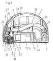
- FIG. 1is a vertical section through a first embodiment of the insertion device according to the present invention, in the non-pretensioned state and without an insertion head;
- FIG. 2is a view of the insertion device of FIG. 1 , but with an insertion head arranged in it;
- FIG. 3is a vertical section through the insertion device of FIGS. 1 and 2 , during pretensioning, and with the insertion head arranged in it;
- FIG. 4is a vertical section through the insertion device of the preceding figures, in the pretensioned state and with an insertion head arranged therein in the secured state ready for application;
- FIG. 5is a view of the insertion device of FIG. 4 , but in the released state;
- FIG. 6is a view of the insertion device of FIG. 5 , but shortly after the actuation of the trigger button;
- FIG. 7is a vertical section through a second embodiment of the insertion device according to the present invention, in the non-pretensioned state and with an insertion head arranged therein;
- FIG. 8is a vertical section through the insertion device of FIG. 7 , in the pretensioned and released state;
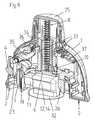
- FIG. 9is a vertical section through a third embodiment of the insertion device according to the present invention, in the non-pretensioned state, with an insertion head arranged therein;
- FIG. 10is a vertical section through the insertion device of FIG. 9 , in the pretensioned and released state.
- fastening, mounting, attaching or connecting components of the present inventionunless specifically described as otherwise, conventional mechanical fasteners and methods may be used.
- Other appropriate fastening or attachment methodsinclude adhesives, welding and soldering, the latter particularly with regard to the electrical system of the invention, if any.
- suitable electrical components and circuitry, wires, wireless components, chips, boards, microprocessors, inputs, outputs, displays, control components, etc.may be used.
- the materials for making the invention and/or its componentsmay be selected from appropriate materials such as metal, metallic alloys, ceramics, plastics, etc.
- FIG. 1A first embodiment of the insertion device according to the present invention, for insertion heads with deployable infusion cannula, is shown in vertical section in FIG. 1 , in the non-pretensioned state and without an insertion head.
- the insertion devicehas a portal-like housing 1 which, on its underside, has contact faces 2 via which the insertion device is placed and pressed onto the body of a patient for application of an infusion set using the insertion device.
- One of the contact faces 2is formed by a securing button 3 , which protrudes or extends downwardly from the underside of the housing 1 and which, to release the insertion device, when the latter is in a state ready for application or use by being placed and pressed onto the body of the patient, can be displaced into a release position in which the contact face 2 of the securing button 3 is essentially flush with that surface of the contact face 2 of the housing 1 adjoining the securing button 3 .
- the insertion devicealso has a trigger knob 4 with which the insertion movement for applying the insertion head to the body of the patient can be triggered or initiated when the insertion device is in a state ready for use and the securing button 3 is arranged in the release position.
- the securing button 3 and trigger knob 4thus represent two actuation members which have to be actuated simultaneously in order to trigger the insertion movement.
- the insertion devicein the situation shown in FIG. 1 , has, on its underside, a receiving aperture 5 which is formed by a slide element 6 and in which projections 7 are mounted which are resilient under the effect of the slide element 6 and with which an infusion set to be applied can be held in the receiving aperture 5 , in the present case exclusively with a force fit.
- the insertion devicecomprises, as a driver or drive means, a helical spring 8 which acts on a hammer element 9 which, in the situation shown, bears on a catch projection 10 of the slide element 6 .
- FIGS. 2 , 3 and 4show the insertion device in the state as before, but with an insertion head 12 engaged into the receiving aperture ( FIG. 2 ), during pretensioning with the insertion head 12 held therein ( FIG. 3 ), and in the pretensioned and secured state ready for application or use ( FIG. 4 ), to effect pretensioning and at the same time to deploy the infusion cannula 11 of the infusion set 12 , the housing 1 is gripped with one hand and the slide element 6 is gripped with the other hand and, with the infusion set 12 held therein, is moved upwards relative to the housing 1 , entraining the hammer element 9 with it and resulting in increased pretensioning of the helical spring 8 . Since the slide element 6 , in its upward movement, only frees the portal opening of the housing 1 , and in its uppermost position does not protrude above or extend beyond the top edge of the housing 1 , the overall dimensions of the insertion device remain unchanged.
- the cannula 11 of the insertion head 12is deployed, by an actuation lever 23 mounted pivotably on the slide element 6 running on or moving along a control ramp 39 in the housing 1 and being pivoted toward the insertion head 12 , thus pushing the left-hand housing part 13 of the insertion head 12 , which forms a displaceable actuation member of the insertion head 12 , into the right-hand housing part 14 and thus deploys the cannula 11 via a mechanism (not shown) located in the interior of the insertion head.
- the insertion heads 12 shown in the illustrative embodimentsare exclusively infusion sets for insulin, which, in the states shown here prior to application, have a flexible cannula (soft cannula) supported by a puncture needle that is to be removed following the application.
- a flexible cannulasoft cannula
- the present inventionmay be adapted for use with infusion sets suitable for use with other substances, or for use with other infusion sets.
- puncture needle and flexible cannulafor which reason both are each together designated as “cannula 11 ”.
- a trigger lever 15which is designed as a double lever and is guided at its first end with a guide cylinder (not shown), like a guide block, in a horizontal oblong hole 16 on the rear face of the hammer element 9 , is pivoted about a bearing point in the housing 1 , whereby a run-up ramp 17 formed at its second end moves a latch element 18 downwardly counter to the force of a locking spring 19 until it extends past the latch element 18 and then is locked in the situation shown in FIG. 4 by the latch element 18 shooting or moving back under the force of the spring.
- the hammer element 9 in this situationis held by the trigger lever 15 in the upper position shown in FIG. 4 , counter to the force of the pretensioned spring 8 .
- Suitable catch meansare known to a person skilled in the art and could be formed, for example, by a lug held on a spring tongue and engaging with a run-on bevel in an undercut such that the locked connection can be released again by deflection of the spring tongue under increased force, by the run-on bevel running onto an edge of the undercut.
- FIGS. 4 and 5show the insertion device in the state ready for application or use, on the one hand in the secured state ( FIG. 4 ) and on the other hand in the released state ( FIG. 5 ), the securing button 3 , on which the locking spring 19 bears via its end directed away from the latch element 18 , forms a securing slide 22 in the housing 1 , which securing slide 22 , in the situation shown in FIG. 4 , has a form fit and prevents actuation of the trigger knob 4 .
- FIG. 6which shows the insertion device shortly after actuation of the trigger knob 4
- the trigger knob 4has, on its face directed toward the interior of the housing 1 , a trigger ramp 24 which, upon actuation of the trigger knob 4 , is moved along a control edge of the latch element 18 and thus draws the latter downwardly counter to the force of the locking spring 19 , as a result of which the locked second end of the trigger latch 15 is freed and the hammer element 9 held at the first end thereof shoots downwardly, driven by the force of the pretensioned helical spring 8 .
- the hammer element 9strikes the top face of the insertion head 12 held with a force fit in the first position in the slide element 6 , releases the insertion head 12 from the catch projections 7 and drives it down for application or placement of the insertion head 12 on the body of a patient, with the cannula 11 penetrating into the body ahead of it, until the cannula 11 is completely inserted and the insertion head 12 lies with its underside on the surface of the body.
- the slide element 6 with the catch projections 7remains unmoved relative to the housing 1 and, for application of a further insertion head 12 , first has to be brought back to the engage position, by being moved downwardly relative to the housing 1 after overcoming an initially high resistance.
- the applied insertion head 12is completely separated from the insertion device, such that the latter can be removed without causing any irritation of the application site.
- FIGS. 7 and 8A second embodiment of the insertion device according to the present invention, likewise for an infusion set with deployable infusion cannula, is shown in vertical section in FIGS. 7 and 8 , on the one hand in the non-pretensioned state with an insertion head already engaged in it ( FIG. 7 ) and on the other hand in the pretensioned and released state with an infusion set arranged ready for application in the first position ( FIG. 8 ).
- this insertion devicetoo comprises a portal-like housing 1 which, on its underside, has contact faces 2 via which the insertion device is placed and pressed onto the body of a patient for application or placement of an infusion set using the insertion device.
- a securing button 3which protrudes downwardly from the underside of the housing 1 and which, to release the insertion device, when the latter is in a state ready for application or use by being placed and pressed onto the body of the patient, can be displaced into a release position in which the contact face 2 of the securing button 3 is essentially flush with the contact face 2 of the housing 1 adjoining the securing button 3 (see FIG. 8 ).
- the insertion devicealso has a trigger knob 4 with which the insertion movement for applying the insertion head to the body of the patient can be triggered when the insertion device is in the state shown in FIG. 8 .
- the securing button 3 and trigger knob 4thus also in this case represent two actuation members 3 , 4 , which have to be actuated simultaneously to trigger or initiate the insertion movement.
- This insertion device tooin the relaxed state without insertion head (as in FIG. 7 , but without an engaged infusion set), has, on its underside, a receiving aperture which is formed by a receiving element 26 mounted vertically displaceably in the housing 1 and in which projections (not shown) are mounted which are resilient under the effect of the receiving element 26 and with which the infusion set 12 is held in the receiving aperture, exclusively with a force fit in both of the situations shown.
- the insertion devicecomprises, as at least a part of a driver or drive means, a torsion spring 8 which acts on a hammer element 9 via a trigger lever 15 .
- the trigger lever 15is mounted so as to rotate about the rotation centre of the torsion spring 8 in the housing and has, at its end remote from the rotation centre, a guide cylinder 30 which, like a sliding block, is guided in a horizontal oblong hole 16 in the hammer element 9 .
- the housing 1is gripped with one hand, and a slide element 6 displaceable along the outer contour of the housing 1 is gripped with the other hand, and the slide element 6 is then displaced from the position shown in FIG. 7 to the position shown in FIG. 8 . It is likewise possible for the slide element 6 to be operated using the same hand with which the housing 1 is held.
- the figuresdo not show how, during the displacement of the slide element 6 , a guide (not shown) formed by the latter is guided along a guide cylinder 28 of a tension lever 29 , as a result of which the tension lever 29 is guided upwardly.
- the tension lever 29On the rear face, the tension lever 29 has, lying opposite the guide cylinder 28 , a further cylinder (not visible) which engages under a detent 10 mounted in the hammer element 9 .
- the tension lever 29carries the hammer element 9 up with it via the cylinder and the detent 10 , which hammer element 9 in turn entrains the trigger lever 15 upwardly from the position shown in FIG. 7 to the position shown in FIG.
- the cylinder of the tension lever 29slides horizontally along the underside of the detent 10 , until, at the end of the pretensioning movement, it is arranged next to the detent 10 , that is to say disengaged from the detent 10 .
- the trigger lever 15has, at its end forming the rotation centre, a locking element 27 which, during its pivoting movement, is guided in a sliding movement along a latch element 18 acted upon by the force of a locking spring 19 , until it extends past the latch element 18 and is then locked by the latter in the pretensioned situation shown in FIG. 8 .
- This lockingtakes place shortly before the cylinder of the tension lever 29 disengages from the detent 10 .
- the hammer element 9is held by the trigger lever 15 in the upper position shown in FIG. 8 .
- the hammer element 9also entrains the slide element 26 , which in turn, by a carrier lug 31 formed by it, entrains an activation lever 23 that is mounted rotatably on the trigger lever 15 counter to the force of an auxiliary spring.
- the activation lever 23is pivoted towards the insertion head 12 , thus pushing the left-hand housing part 13 of the insertion head 12 , which forms a displaceable actuation member of the insertion head 12 , into the right-hand housing part 14 and thus deploying the cannula 11 via a mechanism (not shown) located in the interior of the insertion head.
- catch meansare known to a person skilled in the art and could also be formed here, for example, by a lug held on a spring tongue and engaging with a run-on bevel in an undercut, such that the locked connection can be released again by deflection of the spring tongue under increased force, by the run-on bevel running onto an edge of the undercut.
- the securing button 3on which the locking spring 19 bears via its end directed away from the latch element 18 , forms a securing slide 22 in the housing 1 , which securing slide 22 , in the situation shown in FIG. 7 , has a form fit and prevents actuation of the trigger knob 4 .
- the trigger knob 4has, on its face directed toward the interior of the housing 1 , a trigger ramp (not visible) which, upon actuation of the trigger knob 4 , is moved along a control edge of the latch element 18 and thus draws the latter downwardly counter to the force of the locking spring 19 , as a result of which the locking element 27 of the trigger lever 15 is freed and the hammer element 9 held at the first end thereof shoots or moves downwardly, driven by the force of the pretensioned torsion spring 8 .
- the hammer element 9strikes the top face of the insertion head 12 held with a force fit in the first position in the slide element 6 , releases the insertion head 12 from the catch projections and drives it down for application or placement of the insertion head 12 to the body of the patient, with the cannula 11 penetrating into the body ahead of it, until the cannula 11 is completely inserted and the insertion head 12 lies with its underside, which is formed by an adhesive pad 32 , on the surface of the body.
- the receiving element 26remains unmoved relative to the housing 1 and, for application of a further insertion head 12 , first has to be brought back to the engage position. For this purpose, the slide 6 is brought back into the position shown in FIG.
- FIGS. 9 and 10A third embodiment of the insertion device according to the present invention, likewise for an infusion set with deployable infusion cannula, is shown in vertical section in FIGS. 9 and 10 , on the one hand in the non-pretensioned state with an insertion head already engaged in it ( FIG. 9 ) and on the other hand in the pretensioned and released state with an infusion set arranged ready for application therein in the claimed first position ( FIG. 10 ).
- this embodiment of an insertion device in accordance with the present inventioncomprises a portal-like housing 1 which, on its underside, has contact faces 2 via which the insertion device is placed and pressed onto the body of a patient for application of an infusion set using the insertion device.
- One of the contact faces 2is again formed by a securing button 3 , which, as in the two exemplary embodiments already described above, protrudes or extends downwardly from the underside of the housing 1 and which, in order to release the insertion device, when the latter is in a state ready for application by being placed and pressed onto the body of the patient, can be displaced into a release position in which the contact face 2 of the securing button 3 is essentially flush with the contact face 2 of the housing 1 adjoining the securing button 3 (see FIG. 10 ).
- the insertion device in this casealso has a trigger knob 4 with which the insertion movement for applying the insertion head to the body of the patient can be triggered or initiated when the insertion device is in the state according to FIG. 10 .
- the securing button 3 and trigger knob 4thus also in this case represent two actuation members 3 , 4 , which have to be actuated simultaneously to trigger the insertion movement.
- This insertion device tooin the non-pretensioned state without insertion head (as in FIG. 9 , but without an engaged infusion set), has, on its underside, a receiving aperture which is formed by a receiving element 26 mounted vertically displaceably in the housing 1 and in which retention means (not shown) formed by the receiving element 26 are arranged, with which the infusion set 12 is held in the receiving aperture with a force fit.
- the insertion devicelike the first embodiment described, comprises, as a drive means, driver or portion thereof, a helical spring 8 which acts directly on a hammer element 9 which, in the situations shown, bears with a catch projection 10 on the receiving element 26 .
- the helical spring 8is surrounded coaxially by substantially cylindrically shaped sections of the hammer element 9 and of the receiving element 26 .
- the cylindrical section of the receiving element 26has guides 33 in which slide blocks (not visible) of a rotary sleeve 34 surrounding this section of the receiving element 26 engage.
- the rotary sleeve 34is in turn mounted rotatably in the housing 1 , but is axially immovable relative to the force direction of the spring 8 , and it carries a rotary knob 25 , with the helical spring 8 bearing on the inner face of the latter.
- the housing 1 of the insertion device located in the state according to FIG. 9is gripped with one hand, and the rotary knob 25 is turned through approximately 120° with the other hand, which leads to a corresponding turning of the rotary sleeve 34 relative to the housing 1 .
- its slide blocksare displaced inside the guides 33 of the receiving element 26 and, as a result, the receiving element 26 , with the infusion set 12 held therein, is lifted from the position shown in FIG. 9 to the position shown in FIG. 10 , with the hammer element 9 being entrained, and with corresponding increased pretensioning of the helical spring 8 .
- the rotary knob 25 in this rotation positionlocks reversibly on the housing 1 via catch means (not shown) such that it can be turned further, or turned in the opposite direction, only when a high initial resistance is overcome.
- Suitable catch meansare known to a person skilled in the art and could also be formed, for example, by a lug held on a spring tongue and engaging with a run-on bevel in an undercut, such that the locked connection can be released again by deflection of the spring tongue under increased force, by the run-on bevel running onto an edge of the undercut.
- the retention element 26Since, when it moves upwards, the retention element 26 only frees the portal opening of the housing 1 , and remains inside the housing 1 , the overall dimensions of the insertion device remain unchanged in this case too, in the same way as in the first embodiment of the insertion device according to the present invention.
- the cannula 11 of the insertion head 12is deployed by means of one of the two arms of an activation lever 23 , mounted in the housing 1 and designed as a double lever, being entrained by the receiving element 26 (not visible because of the sectional depiction) and, in this way, its second arm is pivoted toward the insertion head 12 , thus pushing the left-hand housing part 13 of the insertion head 12 , which forms a displaceable actuation member of the insertion head 12 , into the right-hand housing part 14 and thus deploying the cannula 11 via a mechanism (not shown) located in the interior of the insertion head.
- the securing button 3is forced out by the force of a spring 19 and forms, in the housing 1 , a securing slide 22 which, in the situation shown in FIG. 9 , prevents actuation of the trigger knob 4 .
- a pressure forceis exerted on the securing button 3 counter to the direction of force of the spring 19 , for example by pressing the insertion device onto the application site on the body of a patient, can it be pushed so far into the housing 1 that its underside bearing a contact face 2 is essentially flush with the contact face 2 of the housing 1 adjoining it. In this position, which is shown in FIG. 10 , the securing slide 22 frees the trigger knob 4 .
- the trigger knob 4is mounted pivotably about the rotation axis of the activation lever 23 in the housing 1 and forms, inside the housing 1 , a trigger lever 35 which runs or moves on a control edge of a trigger slide 36 mounted horizontally displaceably and axially non-displaceably in the housing 1 relative to the force direction of the drive spring 8 , such that an actuation of the trigger button 4 displaces the trigger slide 36 to the left counter to the force of a restoring spring 37 .
- the catch projection 10with which the hammer element 9 acted upon by the force of the helical spring 8 bears on the receiving element 26 , is forced toward the left and in doing so disengages from the receiving element 26 , such that the hammer element 9 moves downwardly, driven by the force of the spring 8 and guided within the cylindrical section of the retention element 26 .
- the hammer element 9strikes the top face of the insertion head 12 held with a force fit in the first position in the slide element 26 , releases the insertion head 12 from the retention means and drives it down for application of the insertion head 12 on the body of a patient, with the cannula 11 penetrating into the body ahead of it, until the cannula 11 is completely inserted and the insertion head 12 lies with its underside, which is here formed by an adhesive plaster 32 , on the surface of the body.
- the retention element 26 with the retention meansremains unmoved relative to the housing 1 in the upper position and, for application of a further insertion head 12 , first has to be brought back to the engage position, by turning the rotary knob 25 relative to the housing 1 so as to overcome an initially high resistance.
- the cylindrical section of the retention element 26has guides 33 which are shaped like spiral sections and which alternately turn left and right, it is immaterial whether the rotary knob 25 is turned right or left for transferring the insertion device from the engage position to the standby position or for resetting the retention element after the application, since any rotation, in whichever direction, in each case leads to the state that is wanted.
Landscapes
- Health & Medical Sciences (AREA)
- Vascular Medicine (AREA)
- Engineering & Computer Science (AREA)
- Anesthesiology (AREA)
- Biomedical Technology (AREA)
- Heart & Thoracic Surgery (AREA)
- Hematology (AREA)
- Life Sciences & Earth Sciences (AREA)
- Animal Behavior & Ethology (AREA)
- General Health & Medical Sciences (AREA)
- Public Health (AREA)
- Veterinary Medicine (AREA)
- Infusion, Injection, And Reservoir Apparatuses (AREA)
- Media Introduction/Drainage Providing Device (AREA)
Abstract
Description
Claims (34)
Applications Claiming Priority (3)
| Application Number | Priority Date | Filing Date | Title |
|---|---|---|---|
| EP07005216.2 | 2007-03-14 | ||
| EP07005216AEP1970084B8 (en) | 2007-03-14 | 2007-03-14 | Insertion device for an insertion head, in particular for an infusion set |
| EP07005216 | 2007-03-14 |
Publications (2)
| Publication Number | Publication Date |
|---|---|
| US20080249473A1 US20080249473A1 (en) | 2008-10-09 |
| US7815607B2true US7815607B2 (en) | 2010-10-19 |
Family
ID=38318645
Family Applications (1)
| Application Number | Title | Priority Date | Filing Date |
|---|---|---|---|
| US12/047,643Active2028-07-07US7815607B2 (en) | 2007-03-14 | 2008-03-13 | Insertion device for an insertion head, in particular for an infusion set |
Country Status (8)
| Country | Link |
|---|---|
| US (1) | US7815607B2 (en) |
| EP (1) | EP1970084B8 (en) |
| JP (1) | JP2008220961A (en) |
| CN (1) | CN101264354B (en) |
| AT (1) | ATE477011T1 (en) |
| CA (1) | CA2624083A1 (en) |
| DE (1) | DE502007004715D1 (en) |
| DK (1) | DK1970084T3 (en) |
Cited By (8)
| Publication number | Priority date | Publication date | Assignee | Title |
|---|---|---|---|---|
| US8409145B2 (en) | 2007-09-17 | 2013-04-02 | Tecpharma Licensing Ag | Insertion devices for infusion devices |
| US9119528B2 (en) | 2012-10-30 | 2015-09-01 | Dexcom, Inc. | Systems and methods for providing sensitive and specific alarms |
| US20160030667A1 (en)* | 2014-07-29 | 2016-02-04 | Tecpharma Licensing Ag | Insertion device for an infusion set |
| EP3097933A1 (en) | 2015-05-26 | 2016-11-30 | Roche Diabetes Care GmbH | Cartridge and inserter for a medical system |
| US9615779B2 (en) | 2012-04-04 | 2017-04-11 | Dexcom, Inc. | Transcutaneous analyte sensors, applicators therefor, and associated methods |
| US9731069B2 (en) | 2012-09-27 | 2017-08-15 | Becton, Dickinson And Company | Perpendicular infusion set and disposable inserter |
| US10278732B2 (en) | 2015-10-21 | 2019-05-07 | Dexcom, Inc. | Transcutaneous analyte sensors, applicators therefor, and associated methods |
| US11446434B2 (en) | 2019-02-22 | 2022-09-20 | Deka Products Limited Partnership | Infusion set and inserter assembly systems and methods |
Families Citing this family (85)
| Publication number | Priority date | Publication date | Assignee | Title |
|---|---|---|---|---|
| US20190357827A1 (en) | 2003-08-01 | 2019-11-28 | Dexcom, Inc. | Analyte sensor |
| WO2009048462A1 (en) | 2007-10-09 | 2009-04-16 | Dexcom, Inc. | Integrated insulin delivery system with continuous glucose sensor |
| US9656019B2 (en) | 2007-10-02 | 2017-05-23 | Medimop Medical Projects Ltd. | Apparatuses for securing components of a drug delivery system during transport and methods of using same |
| US7967795B1 (en) | 2010-01-19 | 2011-06-28 | Lamodel Ltd. | Cartridge interface assembly with driving plunger |
| BRPI0817907B8 (en) | 2007-10-02 | 2021-06-22 | Lamodel Ltd | apparatus for administering a substance to an individual |
| US9345836B2 (en) | 2007-10-02 | 2016-05-24 | Medimop Medical Projects Ltd. | Disengagement resistant telescoping assembly and unidirectional method of assembly for such |
| US10420880B2 (en) | 2007-10-02 | 2019-09-24 | West Pharma. Services IL, Ltd. | Key for securing components of a drug delivery system during assembly and/or transport and methods of using same |
| US8231577B2 (en)* | 2008-06-26 | 2012-07-31 | Calibra Medical, Inc. | Disposable infusion device with automatically releasable cannula driver |
| US12097357B2 (en) | 2008-09-15 | 2024-09-24 | West Pharma. Services IL, Ltd. | Stabilized pen injector |
| US9393369B2 (en) | 2008-09-15 | 2016-07-19 | Medimop Medical Projects Ltd. | Stabilized pen injector |
| US10071198B2 (en) | 2012-11-02 | 2018-09-11 | West Pharma. Servicees IL, Ltd. | Adhesive structure for medical device |
| USD810279S1 (en) | 2009-09-15 | 2018-02-13 | Medimop Medical Projects Ltd. | Injector device |
| US8157769B2 (en) | 2009-09-15 | 2012-04-17 | Medimop Medical Projects Ltd. | Cartridge insertion assembly for drug delivery system |
| US10071196B2 (en) | 2012-05-15 | 2018-09-11 | West Pharma. Services IL, Ltd. | Method for selectively powering a battery-operated drug-delivery device and device therefor |
| ATE553800T1 (en) | 2009-11-26 | 2012-05-15 | Hoffmann La Roche | EXTERNALLY TRIGGERABLE CANNULA ARRANGEMENT |
| US8348898B2 (en) | 2010-01-19 | 2013-01-08 | Medimop Medical Projects Ltd. | Automatic needle for drug pump |
| EP2569031B1 (en) | 2010-05-10 | 2017-10-11 | Medimop Medical Projects Ltd. | Low volume accurate injector |
| US8919452B2 (en) | 2010-11-08 | 2014-12-30 | Baker Hughes Incorporated | Casing spears and related systems and methods |
| US8998851B2 (en)* | 2011-02-09 | 2015-04-07 | Becton, Dickinson And Company | Compact spring inserter for drug deliver infusion set |
| CA2826094C (en) | 2011-02-09 | 2020-11-10 | Becton, Dickinson And Company | Subcutaneous infusion device |
| EP2495001A1 (en)* | 2011-03-03 | 2012-09-05 | Debiotech S.A. | Cannula inserter |
| USD702834S1 (en) | 2011-03-22 | 2014-04-15 | Medimop Medical Projects Ltd. | Cartridge for use in injection device |
| EP2697650B1 (en) | 2011-04-15 | 2020-09-30 | Dexcom, Inc. | Advanced analyte sensor calibration and error detection |
| US9072827B2 (en) | 2012-03-26 | 2015-07-07 | Medimop Medical Projects Ltd. | Fail safe point protector for needle safety flap |
| IL221634A0 (en) | 2012-08-26 | 2012-12-31 | Medimop Medical Projects Ltd | Universal drug vial adapter |
| US9421323B2 (en) | 2013-01-03 | 2016-08-23 | Medimop Medical Projects Ltd. | Door and doorstop for portable one use drug delivery apparatus |
| EP2964297B1 (en)* | 2013-03-08 | 2020-05-06 | Interquim, S.A. | Inhaler |
| US9011164B2 (en) | 2013-04-30 | 2015-04-21 | Medimop Medical Projects Ltd. | Clip contact for easy installation of printed circuit board PCB |
| DE212014000169U1 (en) | 2013-08-07 | 2016-03-14 | Medimop Medical Projects Ltd. | Fluid transfer devices for use with infusion fluid containers |
| CN103750818B (en)* | 2013-12-25 | 2016-03-30 | 浙江凯立特医疗器械有限公司 | For the quick implantation device of implantating biological sensors |
| WO2015122964A1 (en) | 2014-02-11 | 2015-08-20 | Dexcom, Inc. | Packaging system for analyte sensors |
| JP6358724B2 (en) | 2015-01-05 | 2018-07-18 | ウエスト・ファーマ.サービシーズ・イスラエル,リミテッド | Dual vial adapter assembly with easy removable pill adapter to ensure accurate use |
| US10293120B2 (en) | 2015-04-10 | 2019-05-21 | West Pharma. Services IL, Ltd. | Redundant injection device status indication |
| US10149943B2 (en) | 2015-05-29 | 2018-12-11 | West Pharma. Services IL, Ltd. | Linear rotation stabilizer for a telescoping syringe stopper driverdriving assembly |
| CN113181477B (en) | 2015-06-04 | 2023-07-14 | 麦迪麦珀医疗工程有限公司 | Cartridge insertion for drug delivery device |
| WO2017009822A1 (en) | 2015-07-16 | 2017-01-19 | Medimop Medical Projects Ltd | Liquid drug transfer devices for secure telescopic snap fit on injection vials |
| KR101773478B1 (en) | 2015-08-21 | 2017-08-31 | 엘지전자 주식회사 | Water purifier |
| US9987432B2 (en) | 2015-09-22 | 2018-06-05 | West Pharma. Services IL, Ltd. | Rotation resistant friction adapter for plunger driver of drug delivery device |
| US10576207B2 (en) | 2015-10-09 | 2020-03-03 | West Pharma. Services IL, Ltd. | Angled syringe patch injector |
| US11318254B2 (en) | 2015-10-09 | 2022-05-03 | West Pharma. Services IL, Ltd. | Injector needle cap remover |
| CN115721558A (en) | 2015-11-25 | 2023-03-03 | 西部制药服务以色列有限公司 | Dual vial adapter assembly comprising a drug vial adapter having a self-sealing inlet valve |
| EP4026488B1 (en) | 2015-12-30 | 2023-07-19 | Dexcom, Inc. | Transcutaneous analyte sensor systems and methods |
| USD806232S1 (en) | 2016-01-21 | 2017-12-26 | Becton, Dickinson And Company | Drug delivery device with insertion mechanism |
| USD830547S1 (en) | 2016-01-21 | 2018-10-09 | Becton, Dickinson And Company | Adhesive liner for wearable drug delivery device |
| USD829889S1 (en) | 2016-01-21 | 2018-10-02 | Becton, Dickinson And Company | Wearable drug delivery device with adhesive |
| USD857191S1 (en) | 2016-01-21 | 2019-08-20 | Becton, Dickinson And Company | Wearable drug delivery device |
| US10646643B2 (en) | 2016-01-21 | 2020-05-12 | West Pharma. Services IL, Ltd. | Needle insertion and retraction mechanism |
| USD805631S1 (en) | 2016-01-21 | 2017-12-19 | Becton, Dickinson And Company | Drug delivery device with insertion mechanism button safety |
| JP6885960B2 (en) | 2016-01-21 | 2021-06-16 | ウェスト ファーマ サービシーズ イスラエル リミテッド | Drug delivery device with visual indicators |
| USD830537S1 (en) | 2016-01-21 | 2018-10-09 | Becton, Dickinson And Company | Wearable drug delivery device with adhesive and liner |
| USD829894S1 (en) | 2016-01-21 | 2018-10-02 | Becton, Dickinson And Company | Wearable drug delivery device baseplate |
| EP3711793B1 (en) | 2016-01-21 | 2021-12-01 | West Pharma Services IL, Ltd. | A method of connecting a cartridge to an automatic injector |
| US11389597B2 (en) | 2016-03-16 | 2022-07-19 | West Pharma. Services IL, Ltd. | Staged telescopic screw assembly having different visual indicators |
| IL245800A0 (en) | 2016-05-24 | 2016-08-31 | West Pharma Services Il Ltd | Dual vial adapter assemblages including identical twin vial adapters |
| IL245803A0 (en) | 2016-05-24 | 2016-08-31 | West Pharma Services Il Ltd | Dual vial adapter assemblages including vented drug vial adapter and vented liquid vial adapter |
| CN109310831B (en) | 2016-06-02 | 2021-11-23 | 西医药服务以色列有限公司 | Three position needle retraction |
| IL246073A0 (en) | 2016-06-06 | 2016-08-31 | West Pharma Services Il Ltd | Fluid transfer devices for use with drug pump cartridge having slidable driving plunger |
| US11338090B2 (en) | 2016-08-01 | 2022-05-24 | West Pharma. Services IL, Ltd. | Anti-rotation cartridge pin |
| JP7059251B2 (en) | 2016-08-01 | 2022-04-25 | ウェスト ファーマ サービシーズ イスラエル リミテッド | A spring that prevents the door from closing halfway |
| JP6970733B2 (en)* | 2016-08-02 | 2021-11-24 | サノフィ−アベンティス・ドイチュラント・ゲゼルシャフト・ミット・ベシュレンクテル・ハフツング | Drug delivery device |
| IL247376A0 (en) | 2016-08-21 | 2016-12-29 | Medimop Medical Projects Ltd | Syringe assembly |
| CA3032455A1 (en) | 2016-09-15 | 2018-03-22 | Becton, Dickinson And Company | Subcutaneous infusion needle stick prevention device using needle hub retraction |
| IL249408A0 (en) | 2016-12-06 | 2017-03-30 | Medimop Medical Projects Ltd | Liquid transfer device for use with infusion liquid container and pincers-like hand tool for use therewith for releasing intact drug vial therefrom |
| IL251458A0 (en) | 2017-03-29 | 2017-06-29 | Medimop Medical Projects Ltd | User actuated liquid drug transfer devices for use in ready-to-use (rtu) liquid drug transfer assemblages |
| EP3630226A1 (en) | 2017-05-30 | 2020-04-08 | West Pharma. Services Il, Ltd. | Modular drive train for wearable injector |
| DK4154802T3 (en) | 2017-06-19 | 2024-03-25 | Dexcom Inc | APPLICATORS FOR THE PLACEMENT OF TRANSCUTANEOUS ANALYTE SENSORS |
| EP4111949B1 (en) | 2017-06-23 | 2023-07-26 | Dexcom, Inc. | Transcutaneous analyte sensors, applicators therefor, and needle hub comprising anti-rotation feature |
| IL254802A0 (en) | 2017-09-29 | 2017-12-31 | Medimop Medical Projects Ltd | Dual vial adapter assemblages with twin vented female vial adapters |
| US20190120785A1 (en) | 2017-10-24 | 2019-04-25 | Dexcom, Inc. | Pre-connected analyte sensors |
| US11331022B2 (en) | 2017-10-24 | 2022-05-17 | Dexcom, Inc. | Pre-connected analyte sensors |
| JP7402799B2 (en) | 2017-12-22 | 2023-12-21 | ウェスト ファーマ サービシーズ イスラエル リミテッド | Syringes available with different cartridge sizes |
| USD888252S1 (en) | 2018-06-18 | 2020-06-23 | Dexcom, Inc. | Transcutaneous analyte sensor applicator |
| USD926325S1 (en) | 2018-06-22 | 2021-07-27 | Dexcom, Inc. | Wearable medical monitoring device |
| JP1630477S (en) | 2018-07-06 | 2019-05-07 | ||
| EP3636298A1 (en)* | 2018-10-10 | 2020-04-15 | Tecpharma Licensing AG | Insertion device for a processing device |
| USD923812S1 (en) | 2019-01-16 | 2021-06-29 | West Pharma. Services IL, Ltd. | Medication mixing apparatus |
| JP1648075S (en) | 2019-01-17 | 2019-12-16 | ||
| JP7209849B2 (en) | 2019-01-18 | 2023-01-20 | ウェスト・ファーマ・サービシーズ・アイエル・リミテッド | Liquid transfer device for use with IV bottles |
| WO2020158814A1 (en)* | 2019-01-30 | 2020-08-06 | 株式会社旭ポリスライダー | Cannula inserter |
| US11918542B2 (en) | 2019-01-31 | 2024-03-05 | West Pharma. Services IL, Ltd. | Liquid transfer device |
| JP7284289B2 (en) | 2019-04-09 | 2023-05-30 | ウェスト ファーマ サービシーズ イスラエル リミテッド | Infusion device with integrated syringe |
| KR20240122586A (en) | 2019-04-30 | 2024-08-12 | 웨스트 파마. 서비시즈 일, 리미티드 | Liquid transfer device with dual lumen iv spike |
| EP3862037A1 (en)* | 2020-02-04 | 2021-08-11 | Ypsomed AG | A needle insertion mechanism for an injection device with an improved impact resistance |
| USD956958S1 (en) | 2020-07-13 | 2022-07-05 | West Pharma. Services IL, Ltd. | Liquid transfer device |
| EP4154926A1 (en)* | 2021-09-27 | 2023-03-29 | Ypsomed AG | An improved needle insertion mechanism for an injection or infusion device |
Citations (75)
| Publication number | Priority date | Publication date | Assignee | Title |
|---|---|---|---|---|
| US4306563A (en) | 1979-11-28 | 1981-12-22 | Firma Pfrimmer & Co. Pharmazeutische Werke Erlangen Gmbh | Catheter for introduction into body cavities |
| US4631058A (en) | 1985-06-24 | 1986-12-23 | Burron Medical, Inc. | Guard for right angle winged infusion needle |
| US4755173A (en) | 1986-02-25 | 1988-07-05 | Pacesetter Infusion, Ltd. | Soft cannula subcutaneous injection set |
| US4835248A (en) | 1986-05-15 | 1989-05-30 | Hoechst Aktiengesellschaft | Biologically degradable polyamide for depot preparations having controlled release of the active compound |
| US4863432A (en) | 1986-09-10 | 1989-09-05 | Critikon, Inc. | Winged catheter assembly |
| US4927603A (en) | 1987-07-02 | 1990-05-22 | Avl Ag | Feeding device for introducing liquid or gaseous samples |
| US4968303A (en) | 1988-09-27 | 1990-11-06 | Eli Lilly And Company | Hypodermic syringe holder |
| US5176662A (en) | 1990-08-23 | 1993-01-05 | Minimed Technologies, Ltd. | Subcutaneous injection set with improved cannula mounting arrangement |
| FR2725902A1 (en) | 1994-10-21 | 1996-04-26 | M2Ct | Hollow needle guard to prevent accidental pricks |
| US5522803A (en) | 1993-03-09 | 1996-06-04 | Pharma Plast International A/S | Infusion set for an intermittent or continuous administration of a therapeutical substance |
| US5545143A (en) | 1993-01-21 | 1996-08-13 | T. S. I. Medical | Device for subcutaneous medication delivery |
| US5584813A (en) | 1995-06-07 | 1996-12-17 | Minimed Inc. | Subcutaneous injection set |
| US5637094A (en)* | 1994-11-04 | 1997-06-10 | Pos-T-Vac, Inc. | Multiple dosage syringe |
| FR2752164A1 (en) | 1996-08-09 | 1998-02-13 | Vygon | Needle to puncture skin e.g. for implanting a chamber under the skin |
| US5814020A (en) | 1995-09-11 | 1998-09-29 | Elan Medical Technlogies Limited | Medicament delivery device |
| US5848990A (en)* | 1993-10-22 | 1998-12-15 | Hoffmann-La Roche Inc. | Device for introducing active substance into a patient |
| US5858001A (en) | 1995-12-11 | 1999-01-12 | Elan Medical Technologies Limited | Cartridge-based drug delivery device |
| US5951522A (en) | 1998-11-05 | 1999-09-14 | Millennium Medical Distribution | Hypodermic needle safety enclosure |
| US5957895A (en) | 1998-02-20 | 1999-09-28 | Becton Dickinson And Company | Low-profile automatic injection device with self-emptying reservoir |
| US5968011A (en) | 1997-06-20 | 1999-10-19 | Maersk Medical A/S | Subcutaneous injection set |
| US5980506A (en) | 1998-03-20 | 1999-11-09 | Mathiasen; Orla | Subcutaneous infusion device |
| DE19821723A1 (en) | 1998-05-14 | 1999-11-18 | Disetronic Licensing Ag | Catheter head for subcutaneous administration of an active ingredient |
| US5997504A (en) | 1997-08-08 | 1999-12-07 | Medcare Medical Group, Inc. | Needle removal and containment device and method of using same |
| US6056718A (en) | 1998-03-04 | 2000-05-02 | Minimed Inc. | Medication infusion set |
| US6090068A (en) | 1998-07-23 | 2000-07-18 | Chanut; Stephane | Injection and perfusion device for use in an implantable port access catheter |
| US6355021B1 (en) | 1998-07-14 | 2002-03-12 | Maersk Medical A/S | Medical puncturing device |
| US6379335B1 (en) | 1998-10-12 | 2002-04-30 | D.R.M. S.R.L. | Device for after-use protection of a hypodermic needle, particularly of the butterfly type |
| US6419699B1 (en) | 1999-04-14 | 2002-07-16 | Mcghan Medical Corporation | Universal implant fill connector |
| US20020123724A1 (en) | 2001-03-04 | 2002-09-05 | Douglas Joel S. | Infusion hub assembly and fluid line disconnect system |
| WO2002081012A2 (en) | 2001-04-06 | 2002-10-17 | Disetronic Licensing Ag | Infusion set |
| DE10117286A1 (en) | 2001-04-06 | 2002-10-17 | Disetronic Licensing Ag | Soft cannula |
| US20020193744A1 (en) | 2001-06-19 | 2002-12-19 | Alesi Daniel E. | Needle safety device with antiremoval protection |
| US6500150B1 (en) | 1997-06-16 | 2002-12-31 | Elan Pharma International Limited | Pre-filled drug-delivery device and method of manufacture and assembly of same |
| US6537255B1 (en) | 2000-10-09 | 2003-03-25 | B Braun Medical, Inc. | Huber needle with folding safety wings |
| US20030069546A1 (en) | 2001-10-04 | 2003-04-10 | Sandstrom Jeffrey D. | Right angle safety needle |
| US20030083624A1 (en) | 2001-10-24 | 2003-05-01 | Smith A. David | Intravascular administration set needle safety device |
| US6579267B2 (en) | 2001-01-05 | 2003-06-17 | Applied Diabetes Research, Inc. | Pivoting joint infusion assembly |
| US20030125669A1 (en) | 1997-02-05 | 2003-07-03 | Minimed Inc. | Insertion device for an insertion set and method of using the same |
| US20030181874A1 (en) | 2002-03-20 | 2003-09-25 | Becton, Dickinson And Company | Blood collection device |
| US20040044306A1 (en) | 2001-01-05 | 2004-03-04 | Lynch George R. | Pivoting joint infusion system with seal |
| WO2004029457A1 (en) | 2002-09-27 | 2004-04-08 | Novo Nordisk A/S | Membrane pump with stretchable pump membrane |
| US6749589B1 (en) | 2000-01-18 | 2004-06-15 | Sterling Medications, Inc. | Subcutaneous injection set for use with a reservoir that has a septum |
| US6749588B1 (en) | 1998-04-09 | 2004-06-15 | Becton Dickinson And Company | Catheter and introducer needle assembly with needle shield |
| US6755805B1 (en) | 2002-09-13 | 2004-06-29 | Alan Reid | Needle device having enhanced safety |
| WO2004064898A1 (en) | 2003-01-17 | 2004-08-05 | Disetronic Licensing Ag | Flexible injection needle |
| DE20320207U1 (en) | 2003-06-12 | 2004-10-14 | Disetronic Licensing Ag | Insertion device for an infusion set comprises a thrust linkage which is constituted so that the forward motion of the set takes place without a sliding contact with the device housing |
| US20040215154A1 (en) | 2001-06-06 | 2004-10-28 | Hwang Charles G | Hinged needle shield assembly having needle cannula lock |
| WO2004098682A2 (en) | 2003-05-08 | 2004-11-18 | Novo Nordisk A/S | Pivotable injection needle unit |
| WO2004101071A2 (en) | 2003-05-09 | 2004-11-25 | Medsolve Technologies, L.L.C. | Infusion hub assembly and inserter |
| US6824530B2 (en) | 2001-05-11 | 2004-11-30 | Harmac Medical Products, Inc. | Combination needle assembly and needle safety guard |
| WO2004110527A1 (en) | 2003-06-12 | 2004-12-23 | Disetronic Licensing Ag | Insertion device for infusion sets |
| US20050035014A1 (en) | 2001-12-28 | 2005-02-17 | Mario Cane | Container for disposable needle or cannula |
| DE202004017862U1 (en)* | 2004-11-17 | 2005-02-24 | Clinico Gmbh | Device for extraction of a flexible puncturing needle from a catheter comprises a carriage which is linearly movable on a slide rail, and is provided with a catch for the protruding end of the puncturing needle |
| US6878134B2 (en) | 2002-11-04 | 2005-04-12 | Aragon Medical | Safety needle assembly with locking retraction |
| US6887270B2 (en) | 2002-02-08 | 2005-05-03 | Boston Scientific Scimed, Inc. | Implantable or insertable medical device resistant to microbial growth and biofilm formation |
| WO2005065748A1 (en) | 2003-12-30 | 2005-07-21 | Disetronic Licensing Ag | Insertion unit for puncture devices |
| US6921388B2 (en) | 2002-11-04 | 2005-07-26 | Becton Dickinson Co | Needle assembly |
| US6923791B2 (en) | 2003-03-31 | 2005-08-02 | Sterling Medivations, Inc. | Infusion device having offset flow path |
| DE102004002472A1 (en) | 2004-01-16 | 2005-08-11 | Disetronic Licensing Ag | needle |
| US6949084B2 (en) | 1998-05-14 | 2005-09-27 | Disetronic Licensing Ag | Catheter head for subcutaneous administration of an active substance |
| US6969372B1 (en) | 2003-01-07 | 2005-11-29 | Halseth Thor R | Automatic retraction Huber needle safety enclosure |
| US20060015063A1 (en) | 2002-11-29 | 2006-01-19 | Buetikofer Markus | Catheter head with closeable seal element |
| US6997902B2 (en) | 2003-11-13 | 2006-02-14 | David L. Thorne | Safety shield for medical needles |
| DE102004039408A1 (en) | 2004-08-13 | 2006-03-02 | Disetronic Licensing Ag | Insertion head for medical or pharmaceutical applications |
| EP1652547A1 (en) | 2001-09-27 | 2006-05-03 | Unomedical A/S | Injector device for placing a subcutaneous infusion set |
| US20060173414A1 (en) | 2003-07-21 | 2006-08-03 | Markus Buetikofer | Insertion device for inserting an injection needle |
| USD526409S1 (en) | 1998-07-14 | 2006-08-08 | Unomedical A/S | Medical puncturing device |
| US20060183985A1 (en) | 2004-07-13 | 2006-08-17 | Mark Brister | Analyte sensor |
| US7097637B2 (en) | 2003-08-27 | 2006-08-29 | C. R. Bard, Inc. | Safety needle with positive flush |
| WO2006108185A1 (en) | 2005-04-07 | 2006-10-12 | 3M Innovative Properties Company | System and method for tool feedback sensing |
| US20060229573A1 (en) | 2005-04-08 | 2006-10-12 | Mckinley Medical L.L.L.P. | Adjustable infusion catheter |
| WO2006129196A1 (en) | 2005-04-20 | 2006-12-07 | Becton Dickinson France | Injection set and injection assistance device |
| US7147623B2 (en) | 2002-02-12 | 2006-12-12 | Unomedical A/S | Infusion device with needle shield |
| EP1764125A1 (en) | 2005-09-15 | 2007-03-21 | F.Hoffmann-La Roche Ag | System comprising an insertion head and an inserter |
| US7214207B2 (en) | 2002-03-08 | 2007-05-08 | Applied Diabetes Research, Inc. | Low profile, pivotal connection infusion assembly |
Family Cites Families (1)
| Publication number | Priority date | Publication date | Assignee | Title |
|---|---|---|---|---|
| CN1871042B (en)* | 2003-10-21 | 2010-06-30 | 诺沃挪第克公司 | internal fluid connector |
- 2007
- 2007-03-14ATAT07005216Tpatent/ATE477011T1/enactive
- 2007-03-14DEDE502007004715Tpatent/DE502007004715D1/enactiveActive
- 2007-03-14DKDK07005216.2Tpatent/DK1970084T3/enactive
- 2007-03-14EPEP07005216Apatent/EP1970084B8/enactiveActive
- 2008
- 2008-03-05CACA002624083Apatent/CA2624083A1/ennot_activeAbandoned
- 2008-03-12JPJP2008062063Apatent/JP2008220961A/ennot_activeWithdrawn
- 2008-03-13USUS12/047,643patent/US7815607B2/enactiveActive
- 2008-03-14CNCN2008100865082Apatent/CN101264354B/enactiveActive
Patent Citations (93)
| Publication number | Priority date | Publication date | Assignee | Title |
|---|---|---|---|---|
| US4306563A (en) | 1979-11-28 | 1981-12-22 | Firma Pfrimmer & Co. Pharmazeutische Werke Erlangen Gmbh | Catheter for introduction into body cavities |
| US4631058A (en) | 1985-06-24 | 1986-12-23 | Burron Medical, Inc. | Guard for right angle winged infusion needle |
| US4755173A (en) | 1986-02-25 | 1988-07-05 | Pacesetter Infusion, Ltd. | Soft cannula subcutaneous injection set |
| US4835248A (en) | 1986-05-15 | 1989-05-30 | Hoechst Aktiengesellschaft | Biologically degradable polyamide for depot preparations having controlled release of the active compound |
| US4863432A (en) | 1986-09-10 | 1989-09-05 | Critikon, Inc. | Winged catheter assembly |
| US4927603A (en) | 1987-07-02 | 1990-05-22 | Avl Ag | Feeding device for introducing liquid or gaseous samples |
| US4968303A (en) | 1988-09-27 | 1990-11-06 | Eli Lilly And Company | Hypodermic syringe holder |
| US5176662A (en) | 1990-08-23 | 1993-01-05 | Minimed Technologies, Ltd. | Subcutaneous injection set with improved cannula mounting arrangement |
| US6017328A (en) | 1993-01-21 | 2000-01-25 | Magnolia Medical, Llc | Device for subcutaneous medication delivery |
| US5545143A (en) | 1993-01-21 | 1996-08-13 | T. S. I. Medical | Device for subcutaneous medication delivery |
| US5522803A (en) | 1993-03-09 | 1996-06-04 | Pharma Plast International A/S | Infusion set for an intermittent or continuous administration of a therapeutical substance |
| US5848990A (en)* | 1993-10-22 | 1998-12-15 | Hoffmann-La Roche Inc. | Device for introducing active substance into a patient |
| FR2725902A1 (en) | 1994-10-21 | 1996-04-26 | M2Ct | Hollow needle guard to prevent accidental pricks |
| US5637094A (en)* | 1994-11-04 | 1997-06-10 | Pos-T-Vac, Inc. | Multiple dosage syringe |
| US5584813A (en) | 1995-06-07 | 1996-12-17 | Minimed Inc. | Subcutaneous injection set |
| US5814020A (en) | 1995-09-11 | 1998-09-29 | Elan Medical Technlogies Limited | Medicament delivery device |
| US5858001A (en) | 1995-12-11 | 1999-01-12 | Elan Medical Technologies Limited | Cartridge-based drug delivery device |
| FR2752164A1 (en) | 1996-08-09 | 1998-02-13 | Vygon | Needle to puncture skin e.g. for implanting a chamber under the skin |
| US20030125669A1 (en) | 1997-02-05 | 2003-07-03 | Minimed Inc. | Insertion device for an insertion set and method of using the same |
| US6500150B1 (en) | 1997-06-16 | 2002-12-31 | Elan Pharma International Limited | Pre-filled drug-delivery device and method of manufacture and assembly of same |
| US5968011A (en) | 1997-06-20 | 1999-10-19 | Maersk Medical A/S | Subcutaneous injection set |
| US5997504A (en) | 1997-08-08 | 1999-12-07 | Medcare Medical Group, Inc. | Needle removal and containment device and method of using same |
| US20030199823A1 (en) | 1997-12-31 | 2003-10-23 | Minimed Inc. | Insertion device for an insertion set and method of using the same |
| US6607509B2 (en) | 1997-12-31 | 2003-08-19 | Medtronic Minimed, Inc. | Insertion device for an insertion set and method of using the same |
| US5957895A (en) | 1998-02-20 | 1999-09-28 | Becton Dickinson And Company | Low-profile automatic injection device with self-emptying reservoir |
| US6056718A (en) | 1998-03-04 | 2000-05-02 | Minimed Inc. | Medication infusion set |
| US6520938B1 (en) | 1998-03-04 | 2003-02-18 | Medtronic Minimed, Inc. | Medication infusion set |
| US5980506A (en) | 1998-03-20 | 1999-11-09 | Mathiasen; Orla | Subcutaneous infusion device |
| US6749588B1 (en) | 1998-04-09 | 2004-06-15 | Becton Dickinson And Company | Catheter and introducer needle assembly with needle shield |
| DE19821723A1 (en) | 1998-05-14 | 1999-11-18 | Disetronic Licensing Ag | Catheter head for subcutaneous administration of an active ingredient |
| US6949084B2 (en) | 1998-05-14 | 2005-09-27 | Disetronic Licensing Ag | Catheter head for subcutaneous administration of an active substance |
| US6302866B1 (en) | 1998-05-14 | 2001-10-16 | Disetronic Licensing Ag | Catheter head for subcutaneous administration of an substance |
| US6355021B1 (en) | 1998-07-14 | 2002-03-12 | Maersk Medical A/S | Medical puncturing device |
| USD526409S1 (en) | 1998-07-14 | 2006-08-08 | Unomedical A/S | Medical puncturing device |
| US6840922B2 (en) | 1998-07-14 | 2005-01-11 | Unomedical A/S | Medical puncturing device |
| US20020045867A1 (en) | 1998-07-14 | 2002-04-18 | Maersk Medical A/S | Medical puncturing device |
| US6090068A (en) | 1998-07-23 | 2000-07-18 | Chanut; Stephane | Injection and perfusion device for use in an implantable port access catheter |
| US6379335B1 (en) | 1998-10-12 | 2002-04-30 | D.R.M. S.R.L. | Device for after-use protection of a hypodermic needle, particularly of the butterfly type |
| US5951522A (en) | 1998-11-05 | 1999-09-14 | Millennium Medical Distribution | Hypodermic needle safety enclosure |
| US6261259B1 (en) | 1999-02-24 | 2001-07-17 | Craig J. Bell | Needle removal and containment device and method of using same |
| US6419699B1 (en) | 1999-04-14 | 2002-07-16 | Mcghan Medical Corporation | Universal implant fill connector |
| US6749589B1 (en) | 2000-01-18 | 2004-06-15 | Sterling Medications, Inc. | Subcutaneous injection set for use with a reservoir that has a septum |
| US6537255B1 (en) | 2000-10-09 | 2003-03-25 | B Braun Medical, Inc. | Huber needle with folding safety wings |
| US20030105449A1 (en) | 2000-10-09 | 2003-06-05 | Raines Kenneth C. | Huber needle with folding safety wings |
| US6911020B2 (en) | 2000-10-09 | 2005-06-28 | B. Braun Medical Inc. | Huber needle with folding safety wings |
| US20040044306A1 (en) | 2001-01-05 | 2004-03-04 | Lynch George R. | Pivoting joint infusion system with seal |
| US6579267B2 (en) | 2001-01-05 | 2003-06-17 | Applied Diabetes Research, Inc. | Pivoting joint infusion assembly |
| US20020123724A1 (en) | 2001-03-04 | 2002-09-05 | Douglas Joel S. | Infusion hub assembly and fluid line disconnect system |
| US20040158230A1 (en) | 2001-04-06 | 2004-08-12 | Disetronic Licensing Ag, A Swiss Corporation | Soft Cannula |
| US20040158207A1 (en) | 2001-04-06 | 2004-08-12 | Marcel Hunn | Infusion set |
| WO2002081012A2 (en) | 2001-04-06 | 2002-10-17 | Disetronic Licensing Ag | Infusion set |
| DE10117286A1 (en) | 2001-04-06 | 2002-10-17 | Disetronic Licensing Ag | Soft cannula |
| US6824530B2 (en) | 2001-05-11 | 2004-11-30 | Harmac Medical Products, Inc. | Combination needle assembly and needle safety guard |
| US20040215154A1 (en) | 2001-06-06 | 2004-10-28 | Hwang Charles G | Hinged needle shield assembly having needle cannula lock |
| US20020193744A1 (en) | 2001-06-19 | 2002-12-19 | Alesi Daniel E. | Needle safety device with antiremoval protection |
| EP1652547A1 (en) | 2001-09-27 | 2006-05-03 | Unomedical A/S | Injector device for placing a subcutaneous infusion set |
| US20030069546A1 (en) | 2001-10-04 | 2003-04-10 | Sandstrom Jeffrey D. | Right angle safety needle |
| US6676633B2 (en) | 2001-10-24 | 2004-01-13 | Horizon Medical Products, Inc. | Intravascular administration set needle safety device |
| US20030083624A1 (en) | 2001-10-24 | 2003-05-01 | Smith A. David | Intravascular administration set needle safety device |
| US20050035014A1 (en) | 2001-12-28 | 2005-02-17 | Mario Cane | Container for disposable needle or cannula |
| US6887270B2 (en) | 2002-02-08 | 2005-05-03 | Boston Scientific Scimed, Inc. | Implantable or insertable medical device resistant to microbial growth and biofilm formation |
| US7147623B2 (en) | 2002-02-12 | 2006-12-12 | Unomedical A/S | Infusion device with needle shield |
| US7214207B2 (en) | 2002-03-08 | 2007-05-08 | Applied Diabetes Research, Inc. | Low profile, pivotal connection infusion assembly |
| US20030181874A1 (en) | 2002-03-20 | 2003-09-25 | Becton, Dickinson And Company | Blood collection device |
| US6755805B1 (en) | 2002-09-13 | 2004-06-29 | Alan Reid | Needle device having enhanced safety |
| WO2004029457A1 (en) | 2002-09-27 | 2004-04-08 | Novo Nordisk A/S | Membrane pump with stretchable pump membrane |
| US6878134B2 (en) | 2002-11-04 | 2005-04-12 | Aragon Medical | Safety needle assembly with locking retraction |
| US6921388B2 (en) | 2002-11-04 | 2005-07-26 | Becton Dickinson Co | Needle assembly |
| US20060015063A1 (en) | 2002-11-29 | 2006-01-19 | Buetikofer Markus | Catheter head with closeable seal element |
| US6969372B1 (en) | 2003-01-07 | 2005-11-29 | Halseth Thor R | Automatic retraction Huber needle safety enclosure |
| WO2004064593A2 (en) | 2003-01-17 | 2004-08-05 | Disetronic Licensing Ag | Temperature-sensitive cannula |
| US20060030824A1 (en) | 2003-01-17 | 2006-02-09 | Marcel Hunn | Temperature-sensitive cannula |
| US20050283125A1 (en) | 2003-01-17 | 2005-12-22 | Susanne Barkhahn | Flexible injection needle |
| WO2004064898A1 (en) | 2003-01-17 | 2004-08-05 | Disetronic Licensing Ag | Flexible injection needle |
| US6923791B2 (en) | 2003-03-31 | 2005-08-02 | Sterling Medivations, Inc. | Infusion device having offset flow path |
| WO2004098682A2 (en) | 2003-05-08 | 2004-11-18 | Novo Nordisk A/S | Pivotable injection needle unit |
| WO2004101071A2 (en) | 2003-05-09 | 2004-11-25 | Medsolve Technologies, L.L.C. | Infusion hub assembly and inserter |
| DE20320207U1 (en) | 2003-06-12 | 2004-10-14 | Disetronic Licensing Ag | Insertion device for an infusion set comprises a thrust linkage which is constituted so that the forward motion of the set takes place without a sliding contact with the device housing |
| WO2004110527A1 (en) | 2003-06-12 | 2004-12-23 | Disetronic Licensing Ag | Insertion device for infusion sets |
| US20060173414A1 (en) | 2003-07-21 | 2006-08-03 | Markus Buetikofer | Insertion device for inserting an injection needle |
| US7097637B2 (en) | 2003-08-27 | 2006-08-29 | C. R. Bard, Inc. | Safety needle with positive flush |
| US6997902B2 (en) | 2003-11-13 | 2006-02-14 | David L. Thorne | Safety shield for medical needles |
| WO2005065748A1 (en) | 2003-12-30 | 2005-07-21 | Disetronic Licensing Ag | Insertion unit for puncture devices |
| DE102004002472A1 (en) | 2004-01-16 | 2005-08-11 | Disetronic Licensing Ag | needle |
| US20070016149A1 (en) | 2004-01-16 | 2007-01-18 | Marcel Hunn | Injection Needle |
| US20060183985A1 (en) | 2004-07-13 | 2006-08-17 | Mark Brister | Analyte sensor |
| DE102004039408A1 (en) | 2004-08-13 | 2006-03-02 | Disetronic Licensing Ag | Insertion head for medical or pharmaceutical applications |
| US20070129688A1 (en) | 2004-08-13 | 2007-06-07 | Disetronic Licensing Ag, A Swiss Corporation | Insertion Head for Medical or Pharmaceutical Applications |
| DE202004017862U1 (en)* | 2004-11-17 | 2005-02-24 | Clinico Gmbh | Device for extraction of a flexible puncturing needle from a catheter comprises a carriage which is linearly movable on a slide rail, and is provided with a catch for the protruding end of the puncturing needle |
| WO2006108185A1 (en) | 2005-04-07 | 2006-10-12 | 3M Innovative Properties Company | System and method for tool feedback sensing |
| US20060229573A1 (en) | 2005-04-08 | 2006-10-12 | Mckinley Medical L.L.L.P. | Adjustable infusion catheter |
| WO2006129196A1 (en) | 2005-04-20 | 2006-12-07 | Becton Dickinson France | Injection set and injection assistance device |
| EP1764125A1 (en) | 2005-09-15 | 2007-03-21 | F.Hoffmann-La Roche Ag | System comprising an insertion head and an inserter |
Non-Patent Citations (14)
| Title |
|---|
| European Search Report for 07005215. |
| European Search Report for 07005216. |
| European Search Report for 07005217. |
| US Notice of Allowance dated Apr. 2, 2010 pertaining to U.S. Appl. No. 12/047,551. |
| US Notice of Allowance dated Jun. 7, 2010 pertaining to U.S. Appl. No. 11/673,939. |
| US Office Action dated Dec. 23, 2009 pertaining to U.S. Appl. No. 12/047,551. |
| US Office Action dated Dec. 29, 2009 pertaining to U.S. Appl. No. 11/673,939. |
| US Office Action dated Jan. 11, 2010 pertaining to U.S. Appl. No. 12/047,666. |
| US Office Action dated Jul. 11, 2008 pertaining to U.S. Appl. No. 11/673,939. |
| US Office Action dated Jun. 14, 2007 pertaining to U.S. Appl. No. 11/673,939. |
| US Office Action dated Mar. 24, 2010 pertaining to U.S. Appl. No. 11/673,939. |
| US Office Action dated May 27, 2009 pertaining to U.S. Appl. No. 11/673,939. |
| US Office Action dated Nov. 28, 2007 pertaining to U.S. Appl. No. 11/673,939. |
| US Office Action dated Sep. 17, 2009 pertaining to U.S. Appl. No. 12/047,551. |
Cited By (27)
| Publication number | Priority date | Publication date | Assignee | Title |
|---|---|---|---|---|
| US8409145B2 (en) | 2007-09-17 | 2013-04-02 | Tecpharma Licensing Ag | Insertion devices for infusion devices |
| US9615779B2 (en) | 2012-04-04 | 2017-04-11 | Dexcom, Inc. | Transcutaneous analyte sensors, applicators therefor, and associated methods |
| US11304631B2 (en) | 2012-04-04 | 2022-04-19 | Dexcom, Inc. | Transcutaneous analyte sensors, applicators therefor, and associated methods |
| US9931065B2 (en) | 2012-04-04 | 2018-04-03 | Dexcom, Inc. | Transcutaneous analyte sensors, applicators therefor, and associated methods |
| US10814061B2 (en) | 2012-09-27 | 2020-10-27 | Becton, Dickinson And Company | Perpendicular infusion set and disposable inserter |
| US10398833B2 (en) | 2012-09-27 | 2019-09-03 | Becton, Dickinson And Company | Perpendicular infusion set and disposable inserter |
| US10413660B2 (en) | 2012-09-27 | 2019-09-17 | Becton, Dickinson And Company | Perpendicular infusion set and disposable inserter |
| US9731069B2 (en) | 2012-09-27 | 2017-08-15 | Becton, Dickinson And Company | Perpendicular infusion set and disposable inserter |
| US10143426B2 (en) | 2012-10-30 | 2018-12-04 | Dexcom, Inc. | Systems and methods for dynamically and intelligently monitoring a host's glycemic condition after an alert is triggered |
| US9119529B2 (en) | 2012-10-30 | 2015-09-01 | Dexcom, Inc. | Systems and methods for dynamically and intelligently monitoring a host's glycemic condition after an alert is triggered |
| US9119528B2 (en) | 2012-10-30 | 2015-09-01 | Dexcom, Inc. | Systems and methods for providing sensitive and specific alarms |
| US11026640B1 (en) | 2012-10-30 | 2021-06-08 | Dexcom, Inc. | Systems and methods for dynamically and intelligently monitoring a host's glycemic condition after an alert is triggered |
| US11690577B2 (en) | 2012-10-30 | 2023-07-04 | Dexcom, Inc. | Systems and methods for dynamically and intelligently monitoring a host's glycemic condition after an alert is triggered |
| US9655565B2 (en) | 2012-10-30 | 2017-05-23 | Dexcom, Inc. | Systems and methods for dynamically and intelligently monitoring a host's glycemic condition after an alert is triggered |
| US10555705B2 (en) | 2012-10-30 | 2020-02-11 | Dexcom, Inc. | Systems and methods for dynamically and intelligently monitoring a host's glycemic condition after an alert is triggered |
| US11006903B2 (en) | 2012-10-30 | 2021-05-18 | Dexcom, Inc. | Systems and methods for dynamically and intelligently monitoring a host's glycemic condition after an alert is triggered |
| US10702215B2 (en) | 2012-10-30 | 2020-07-07 | Dexcom, Inc. | Systems and methods for dynamically and intelligently monitoring a host's glycemic condition after an alert is triggered |
| US20160030667A1 (en)* | 2014-07-29 | 2016-02-04 | Tecpharma Licensing Ag | Insertion device for an infusion set |
| US10335543B2 (en)* | 2014-07-29 | 2019-07-02 | Tecpharma Licensing Ag | Insertion device for an infusion set |
| US10737021B2 (en) | 2015-05-26 | 2020-08-11 | Roche Diabetes Care, Inc. | Cartridge and inserter for a medical system |
| US11793934B2 (en) | 2015-05-26 | 2023-10-24 | Roche Diabetes Care, Inc. | Cartridge and inserter for a medical system |
| EP3097933A1 (en) | 2015-05-26 | 2016-11-30 | Roche Diabetes Care GmbH | Cartridge and inserter for a medical system |
| US10278732B2 (en) | 2015-10-21 | 2019-05-07 | Dexcom, Inc. | Transcutaneous analyte sensors, applicators therefor, and associated methods |
| US10595900B2 (en) | 2015-10-21 | 2020-03-24 | Dexcom, Inc. | Transcutaneous analyte sensors, applicators therefor, and associated methods |
| US12357345B2 (en) | 2015-10-21 | 2025-07-15 | Dexcom, Inc. | Transcutaneous analyte sensors, applicators therefor, and associated methods |
| US11446434B2 (en) | 2019-02-22 | 2022-09-20 | Deka Products Limited Partnership | Infusion set and inserter assembly systems and methods |
| US12324899B2 (en) | 2019-02-22 | 2025-06-10 | Deka Products Limited Partnership | Infusion set and inserter assembly systems and methods |
Also Published As
| Publication number | Publication date |
|---|---|
| CA2624083A1 (en) | 2008-09-14 |
| ATE477011T1 (en) | 2010-08-15 |
| EP1970084B8 (en) | 2010-09-22 |
| US20080249473A1 (en) | 2008-10-09 |
| HK1124557A1 (en) | 2009-07-17 |
| DE502007004715D1 (en) | 2010-09-23 |
| DK1970084T3 (en) | 2010-11-22 |
| EP1970084A1 (en) | 2008-09-17 |
| JP2008220961A (en) | 2008-09-25 |
| CN101264354A (en) | 2008-09-17 |
| CN101264354B (en) | 2012-10-03 |
| EP1970084B1 (en) | 2010-08-11 |
Similar Documents
| Publication | Publication Date | Title |
|---|---|---|
| US7815607B2 (en) | Insertion device for an insertion head, in particular for an infusion set | |
| US7771393B2 (en) | Insertion device for an insertion head, in particular for an infusion set | |
| US8870822B2 (en) | Insertion device for insertion heads and infusion sets | |
| US11617827B2 (en) | Invisible needle | |
| EP2046420B1 (en) | Insertion device | |
| US7850652B2 (en) | Insertion head for medical or pharmaceutical applications | |
| CN113164686A (en) | Automatic injection device and cartridge | |
| US20070016129A1 (en) | Insertion Device for Infusion Sets | |
| RU2019139537A (en) | AUTOMATIC INJECTOR WITH HOLLOW PISTON ROD | |
| WO2023138800A1 (en) | Auto injector with a separate distribution system | |
| HK1124557B (en) | Insertion device for an insertion head, in particular for an infusion set | |
| HK1124556B (en) | Insertion device for an insertion head, in particular for an infusion set | |
| US20060149190A1 (en) | Attachment module for an injection device comprising an engagement control for a needle covering element | |
| HK1135049B (en) | Insertion device for insertion heads, in particular for infusion sets | |
| HK1125870A1 (en) | System composed of an insertion head and an inserter | |
| HK1125870B (en) | System composed of an insertion head and an inserter |
Legal Events
| Date | Code | Title | Description |
|---|---|---|---|
| AS | Assignment | Owner name:DISETRONIC LICENSING AG, SWITZERLAND Free format text:ASSIGNMENT OF ASSIGNORS INTEREST;ASSIGNORS:RUTTI, PASCAL;LINIGER, JURG;PEARSON, ALLEN;AND OTHERS;REEL/FRAME:021151/0706;SIGNING DATES FROM 20080411 TO 20080507 Owner name:DISETRONIC LICENSING AG, SWITZERLAND Free format text:ASSIGNMENT OF ASSIGNORS INTEREST;ASSIGNORS:RUTTI, PASCAL;LINIGER, JURG;PEARSON, ALLEN;AND OTHERS;SIGNING DATES FROM 20080411 TO 20080507;REEL/FRAME:021151/0706 | |
| AS | Assignment | Owner name:ROCHE DIAGNOSTICS INTERNATIONAL AG,SWITZERLAND Free format text:MERGER;ASSIGNOR:DISETRONIC LICENSING AG;REEL/FRAME:023920/0695 Effective date:20090508 Owner name:ROCHE DIAGNOSTICS INTERNATIONAL AG, SWITZERLAND Free format text:MERGER;ASSIGNOR:DISETRONIC LICENSING AG;REEL/FRAME:023920/0695 Effective date:20090508 | |
| STCF | Information on status: patent grant | Free format text:PATENTED CASE | |
| FPAY | Fee payment | Year of fee payment:4 | |
| AS | Assignment | Owner name:ROCHE DIABETES CARE, INC., INDIANA Free format text:ASSIGNMENT OF ASSIGNORS INTEREST;ASSIGNOR:ROCHE DIAGNOSTICS INTERNATIONAL AG;REEL/FRAME:043687/0741 Effective date:20170807 | |
| MAFP | Maintenance fee payment | Free format text:PAYMENT OF MAINTENANCE FEE, 8TH YEAR, LARGE ENTITY (ORIGINAL EVENT CODE: M1552) Year of fee payment:8 | |
| MAFP | Maintenance fee payment | Free format text:PAYMENT OF MAINTENANCE FEE, 12TH YEAR, LARGE ENTITY (ORIGINAL EVENT CODE: M1553); ENTITY STATUS OF PATENT OWNER: LARGE ENTITY Year of fee payment:12 |