US7815259B2 - Arm assembly for a chair - Google Patents
Arm assembly for a chairDownload PDFInfo
- Publication number
- US7815259B2 US7815259B2US12/384,253US38425309AUS7815259B2US 7815259 B2US7815259 B2US 7815259B2US 38425309 AUS38425309 AUS 38425309AUS 7815259 B2US7815259 B2US 7815259B2
- Authority
- US
- United States
- Prior art keywords
- plate
- slide plate
- pivot
- armrest
- support post
- Prior art date
- Legal status (The legal status is an assumption and is not a legal conclusion. Google has not performed a legal analysis and makes no representation as to the accuracy of the status listed.)
- Active
Links
- 230000000452restraining effectEffects0.000claims1
- 230000000712assemblyEffects0.000abstractdescription11
- 238000000429assemblyMethods0.000abstractdescription11
- 230000007246mechanismEffects0.000description20
- 238000006073displacement reactionMethods0.000description17
- 230000033001locomotionEffects0.000description16
- 238000009434installationMethods0.000description14
- JOYRKODLDBILNP-UHFFFAOYSA-NEthyl urethaneChemical compoundCCOC(N)=OJOYRKODLDBILNP-UHFFFAOYSA-N0.000description4
- 239000013536elastomeric materialSubstances0.000description4
- 239000000463materialSubstances0.000description4
- 239000002991molded plasticSubstances0.000description4
- NJPPVKZQTLUDBO-UHFFFAOYSA-NnovaluronChemical compoundC1=C(Cl)C(OC(F)(F)C(OC(F)(F)F)F)=CC=C1NC(=O)NC(=O)C1=C(F)C=CC=C1FNJPPVKZQTLUDBO-UHFFFAOYSA-N0.000description4
- 230000000694effectsEffects0.000description3
- 238000003780insertionMethods0.000description3
- 230000037431insertionEffects0.000description3
- 239000004033plasticSubstances0.000description3
- 229920003023plasticPolymers0.000description3
- 210000000245forearmAnatomy0.000description2
- 230000004044responseEffects0.000description2
- 230000000717retained effectEffects0.000description2
- 239000000725suspensionSubstances0.000description2
- 239000004677NylonSubstances0.000description1
- 229910052782aluminiumInorganic materials0.000description1
- XAGFODPZIPBFFR-UHFFFAOYSA-NaluminiumChemical compound[Al]XAGFODPZIPBFFR-UHFFFAOYSA-N0.000description1
- 230000008901benefitEffects0.000description1
- 230000015572biosynthetic processEffects0.000description1
- 238000010276constructionMethods0.000description1
- 229920001577copolymerPolymers0.000description1
- 238000004512die castingMethods0.000description1
- 239000004744fabricSubstances0.000description1
- 238000005755formation reactionMethods0.000description1
- 239000011521glassSubstances0.000description1
- 229920001903high density polyethylenePolymers0.000description1
- 230000008676importEffects0.000description1
- 210000004705lumbosacral regionAnatomy0.000description1
- 229910052751metalInorganic materials0.000description1
- 239000002184metalSubstances0.000description1
- 230000004048modificationEffects0.000description1
- 238000012986modificationMethods0.000description1
- 229920001778nylonPolymers0.000description1
- 230000008707rearrangementEffects0.000description1
- 239000007787solidSubstances0.000description1
Images


Classifications
- A—HUMAN NECESSITIES
- A47—FURNITURE; DOMESTIC ARTICLES OR APPLIANCES; COFFEE MILLS; SPICE MILLS; SUCTION CLEANERS IN GENERAL
- A47C—CHAIRS; SOFAS; BEDS
- A47C1/00—Chairs adapted for special purposes
- A47C1/02—Reclining or easy chairs
- A47C1/022—Reclining or easy chairs having independently-adjustable supporting parts
- A47C1/03—Reclining or easy chairs having independently-adjustable supporting parts the parts being arm-rests
- A47C1/0303—Reclining or easy chairs having independently-adjustable supporting parts the parts being arm-rests adjustable rectilinearly in vertical direction
- A47C1/0305—Reclining or easy chairs having independently-adjustable supporting parts the parts being arm-rests adjustable rectilinearly in vertical direction by peg-and-notch or pawl-and-ratchet mechanism
- A—HUMAN NECESSITIES
- A47—FURNITURE; DOMESTIC ARTICLES OR APPLIANCES; COFFEE MILLS; SPICE MILLS; SUCTION CLEANERS IN GENERAL
- A47C—CHAIRS; SOFAS; BEDS
- A47C1/00—Chairs adapted for special purposes
- A47C1/02—Reclining or easy chairs
- A47C1/022—Reclining or easy chairs having independently-adjustable supporting parts
- A47C1/03—Reclining or easy chairs having independently-adjustable supporting parts the parts being arm-rests
- A47C1/0307—Reclining or easy chairs having independently-adjustable supporting parts the parts being arm-rests adjustable rectilinearly in horizontal direction
- A—HUMAN NECESSITIES
- A47—FURNITURE; DOMESTIC ARTICLES OR APPLIANCES; COFFEE MILLS; SPICE MILLS; SUCTION CLEANERS IN GENERAL
- A47C—CHAIRS; SOFAS; BEDS
- A47C1/00—Chairs adapted for special purposes
- A47C1/02—Reclining or easy chairs
- A47C1/022—Reclining or easy chairs having independently-adjustable supporting parts
- A47C1/03—Reclining or easy chairs having independently-adjustable supporting parts the parts being arm-rests
- A47C1/0308—Reclining or easy chairs having independently-adjustable supporting parts the parts being arm-rests adjustable by rotation
Definitions
- the inventionrelates to an improved arrangement of an arm assembly for an office chair, and more particularly, to an arm assembly wherein the elevation, angular, longitudinal and transverse positions of an arm cap are readily adjustable.
- Conventional office chairsare designed to provide significant levels of comfort and adjustability.
- Such chairstypically include a base which supports a tilt control assembly to which a seat assembly and back assembly are movably interconnected.
- the tilt control mechanismincludes a back upright which extends rearwardly and upwardly and supports the back assembly rearwardly adjacent to the seat assembly.
- the tilt control mechanismserves to interconnect the seat and back assemblies so that they may tilt rearwardly together in response to movements by the chair occupant and possibly to permit limited forward tilting of the seat and back. Further, such chairs typically permit the back to also move relative to the seat during such rearward tilting.
- the chairIn addition to supporting the seat and back of the occupant, the chair also may include support assemblies that support the occupant's body at various locations thereof.
- One primary support assembly of this typeis an arm assembly wherein an arm assembly is mounted on each opposite side of the seat so as to support the arms and specifically, the elbows and forearms of the occupant.
- Such arm assembliesproject upwardly and include an upward facing armrest thereon which armrest defines a support surface to accommodate the occupant's arms.
- An armresttherefore may be movable in its angular orientation as well as its position in the front-to-back direction as well as the side-to-side direction.
- an object of the inventionto provide an improved arm rest assembly which allows ready configurability thereof while providing improved comfort with respect to the range and combination of motions which are permitted.
- the inventionrelates to an arm assembly which not only is height adjustable but also permits adjustment of the armrest in the angular, front-to-back and sideward directions.
- This arm assemblyincludes a support post mounted to the base of the chair and preferably, the upright thereof so that the armrest moves in unison with the upright during tilting of the chair and maintains the arms in a proper orientation relative to the seat and back of the user when reclining.
- the arm assemblyincludes an armrest assembly having a vertically elongate column that projects downwardly and is slidably received within a tubular support post fixed to the chair frame.
- This support postincludes an arrangement of plastic liner sections which fit within the tube and also define vertically spaced apart recesses that correspond to various elevations at which the armrest may be maintained.
- a latch mechanismwhich comprises a vertically movable lever disposed within a hollow interior of the armrest column.
- the latch assemblyfurther includes a cassette assembly which snaps into the side of the column and has a spring-loaded, slidable latch that moves sidewardly into engagement with any of the various recesses located within the post liner.
- the cassette assemblyalso engages with the lever and prevents removal thereof.
- the armrestprovides three directions of movement in addition to height-adjustability.
- the armrestincludes a multi-layer plate arrangement wherein multiple layers of plates are stacked one above the other and are each movable horizontally in an associated direction.
- a first pivot plateis pivotally connected to the armrest column and is maintained in a selected angular position by a first detent.
- the detentdefines multiple angular positions at which the armrest may be maintained while also permitting angular movement of the armrest when the stopping threshold or capacity of the detent is overcome as the occupant manually moves the arm cap at the top of the armrest.
- the pivot detentpreferably comprises a ring of elastomeric material wherein one sidewall of this ring includes a plurality of angularly spaced recesses that define the various angular positions of the armrest. Deflection of this detent wall therefore permits angular movement and defines the stop capacity of the detent.
- a second slide plateis mounted on top of the pivot plate and is slidable relative thereto in the front-to-rear direction.
- a slide detentis fitted within the slide plate wherein this slide detent is fixed to the pivot plate to fasten the slide plate to the pivot plate.
- the slide detentalso selectively restrains the slide plate while also defining a stop threshold above which, the slide plate may be moved upon the user's manual application of a suitable force to the arm cap.
- the slide detentis formed somewhat similar to the pivot detent in that it is a ring of elastomeric material which is deformable. In this case, the slide detent has opposite sidewalls which deflect inwardly.
- an upper transverse subcap plateis slidably supported on the intermediate slide plate through a retainer.
- the subcap plateis sidewardly or transversely slidable while the retainer carries a resiliently deflectable top detent that engages the subcap plate to maintain the subcap plate in a sidewardly adjusted position while defining a stopping threshold above which a force may be applied to the arm cap to permit sideward adjustment thereof.
- the arm capmay be readily adjusted vertically as well as horizontally.
- FIG. 1is a front elevational view of an office chair having arm assemblies of the invention mounted thereon.
- FIG. 2is a side elevational view of the office chair.
- FIG. 3is a rear isometric view of the chair.
- FIG. 4is a front isometric view of the chair.
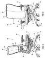
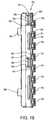
- FIG. 5is an exploded view of the arm assembly comprising a support post assembly and an armrest assembly.
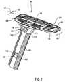
- FIG. 6is an exploded view of the armrest assembly.
- FIG. 7is an assembled isometric view of the armrest assembly.
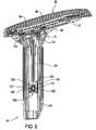
- FIG. 8is a front cross-sectional view of the arm assembly.
- FIG. 9is a side cross-sectional view of the arm assembly.
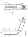
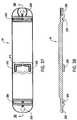
- FIG. 10is a left side view of a chair upright.
- FIG. 11is a partial exploded cross-sectional view of a connector arrangement between the arm assembly and the upright.
- FIG. 12is a front cross-sectional view of a support post.
- FIG. 13is an inner side view of the support post.
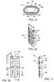
- FIG. 14is a top cross-sectional view of a support column of the armrest assembly as taken along line 14 - 14 of FIG. 25 .
- FIG. 15is an isometric view of a locking liner for the support post.
- FIG. 16is a side view of the locking liner.
- FIG. 17is a front view of the locking liner.
- FIG. 18is a cross-sectional end view of the locking liner as taken along line 18 - 18 of FIG. 16 .
- FIG. 19is a top cross-sectional view of the locking liner as taken along line 19 - 19 of FIG. 16 .
- FIG. 20is an isometric view of a non-locking liner.
- FIG. 21is a side elevational view of the non-locking liner.
- FIG. 22is a top cross-sectional view of the non-locking liner as taken along line 22 - 22 of FIG. 21 .
- FIG. 23is an outside side view and partial cross-section of the armrest column.
- FIG. 24is a front view of the armrest column.
- FIG. 25is an inner side view of the armrest column.
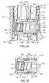
- FIG. 26is an enlarged front cross-sectional view of a latch mechanism mounted within the armrest.
- FIG. 27is a front cross-sectional view of the latch assembly.
- FIG. 28is a rear isometric view of a slidable latch for the latch assembly.
- FIG. 29is a rear isometric view of a latch case or housing.
- FIG. 30is a cross-sectional view of the armrest assembly.
- FIG. 31is a plan view of a pivot detent for the armrest assembly for controlling the angular position of the armrest.
- FIG. 32is a plan view of a slide detent for controlling the longitudinal front-to-back position of the armrest.
- FIG. 33is a plan view of a cam detent for controlling the transverse width position of the armrest.
- FIG. 34is a plan view of a pivot plate with the pivot detent therein.
- FIG. 35is a plan view of a slide plate with the cam detent therein.
- FIG. 36is a plan view of a subcap plate with the cam detent therein.
- FIG. 37is a bottom view of a retainer plate with the cam detent supported thereon.
- FIG. 38is a side cross-sectional view of the retainer plate as taken along line 38 - 38 of FIG. 37 .
- the inventiongenerally relates to an office chair 10 which includes various inventive features therein to improve the overall comfort and adjustability of the chair 10 . More particularly, this chair 10 includes improved height-adjustable arm assemblies 12 which are readily adjustable to the different physical characteristics and comfort preferences of the chair's occupant.
- this chair 10includes a base 13 having radiating legs 14 which are supported on the floor by casters 15 .
- the base 12further includes an upright pedestal 16 which projects vertically and supports a tilt control mechanism 18 on the upper end thereof.
- the pedestal 16has a pneumatic cylinder therein which permits adjustment of the height or elevation of the tilt control mechanism 18 .
- the tilt control mechanism 18includes a control body 19 on which a pair of generally L-shaped uprights 20 are pivotally supported by their front ends.
- the uprights 19converge rearwardly together to define a connector hub 22 on which is supported the back frame 23 of a back assembly 24 .
- the tilt control mechanismis disclosed in U.S. Provisional Patent Application No. 60/657,524, filed Mar. 1, 2005, entitled TENSION ADJUSTMENT MECHANISM FOR A CHAIR, U.S. Provisional Patent Application Nos. 60/657,541, filed Mar. 1, 2005, and 60/689,723, filed Jun. 10, 2005, both entitled TILT CONTROL MECHANISM FOR A CHAIR, which are owned by Haworth, Inc., the common assignee of the present invention.
- the disclosures of these patent applicationsare incorporated herein in their entirety by reference.
- the back assembly 24has a suspension fabric 25 supported about its periphery on the corresponding periphery of the frame 23 to define a suspension surface 26 against which the back of a chair occupant is supported.
- the structure of this back assembly 24is disclosed in U.S. Provisional Patent Application Ser. No. 60/657,313, filed Mar. 1, 2005, entitled CHAIR BACK, which is owned by Haworth, Inc. The disclosure of this patent application is incorporated herein in its entirety by reference.
- the back assembly 24also includes a lumbar support assembly 28 which is configured to support the lumbar region of the occupant's back and is adjustable to improve the comfort of this support.
- a lumbar support assembly 28is disclosed in U.S. Provisional Patent Application Ser. No. 60/657,312, filed Mar. 1, 2005, entitled CHAIR BACK WITH LUMBAR AND PELVIC SUPPORTS, which is owned by Haworth, Inc. The disclosure of this patent application is incorporated herein in its entirety by reference.
- the chair 10includes a slidable seat assembly 30 that defines an upward facing support surface 31 on which the seat of the occupant is supported.
- these arm assemblies 12are formed substantially identical to each other except that they are formed as mirror-images for mounting to the respective left or right side of the chair.
- these arm assemblies 12mount directly to the uprights 20 so as to be movable therewith during reclining of the chair 10 .
- These uprights 20are pivotally connected to the tilt control housing 19 and are pivotable about a horizontal axis to effect rearward pivoting movement of the back assembly in unison with more limited, but downward pivoting of the seat assembly 30 .
- the rearward tilting of the back assembly 24 and seat assembly 30is controlled by the tilt control mechanism 18 .
- FIG. 5is an exploded view of the arm assembly 12 which generally comprises a support post unit 30 and an arm cap or armrest assembly 31 .
- the support post unit 30comprises an upwardly-projecting support post 32 which is rigidly connected to a respective upright 20 and a tubular liner unit 37 which defines an upward-opening hollow interior 38 .
- the hollow post interior 38is adapted to receive the armrest assembly 35 in telescoping relation therewith.
- the armrest assembly 35comprises a downwardly-projecting support column 40 ( FIGS. 5 and 6 ) which is slidably received within the post interior 38 and is vertically movable to a selected elevation.
- the armrest column 40includes a latching mechanism 41 disposed within the post column 40 which is adapted to engage the liner 37 .
- the armrest assembly 35further includes an arm cap 43 ( FIG. 5 ) that defines an upward facing support surface 44 for supporting the fore arms of the occupant.
- the arm cap 43is movably connected to the support column 40 by an interconnected arrangement of stacked plates 46 , 47 , 48 and 49 ( FIGS. 5 and 6 ).
- pivot plate 46pivots relative to the support column 40 to adjust the angular position of the arm cap 43 .
- Slide plate 47is slidably connected to the pivot plate 46 to thereby adjust the longitudinal, front-to-back position of the arm cap 43 .
- a translatable subcap slide plate 48is slidably interconnected to the intermediate slide plate 47 so as to be translatable in the transverse or sideward direction to adjust the relative sideward position of the arm cap 43 .
- the subcap plate 48is fixedly retained on the slide plate 47 by retainer plate 49 as will be discussed in further detail herein.
- This multi-layer arrangement of plates 46 - 49thereby allows a high degree of adjustability for the arm cap 43 to accommodate the physical characteristics and comfort requirements of an occupant.
- FIGS. 6 and 7illustrate the components of the arm rest assembly 35 with FIG. 6 providing a front exploded view of the arm rest components and FIG. 7 providing an assembled view of these same components.
- the arm assembly 12is configured for mounting to a respective one of the uprights 20 with the left-side upright 20 being illustrated in FIG. 10 .
- the right-side upright 20is identical to but a mirror image of the left-side upright 20 ( FIG. 10 ) and thus, a detailed discussion as to the right-side upright 20 is not required.
- Each upright 20includes a front end 51 which is configured so as to be pivotally connected to the control body 19 such that the uprights 20 pivot downwardly and upwardly together about a horizontal axis, which extends across the transverse width of the tilt control mechanism 18 .
- Each upright 20therefore extends rearwardly to an intermediate portion 52 on which is formed an upwardly extending bracket 53 that is adapted to be engaged with and support the seat assembly 30 .
- This intermediate portion 52further includes a connector section having a generally I-shaped mounting socket 55 for engagement with the support post 36 ( FIG. 11 ).
- the side walls of the mounting socket 55taper inwardly as illustrated in FIG. 11 and terminate at a socket bottom wall 57 which closes off the inner end of the socket 55 .
- the bottom wall 57is formed with a fastener bore 58 that is adapted to receive a threaded fastener 59 horizontally therethrough from the interior side of the upright 20 .
- the support post 36has a generally L-shaped configuration defined by a horizontal leg 61 which terminates at an inner end 62 and defines an end face 63 .
- the entire support post 36is formed by die casting of rigid metal, such as aluminum.
- the post 36further includes a connector bayonet 64 that projects sidewardly and has a generally I-shaped cross-sectional configuration as illustrated in FIG. 13 .
- This bayonet 64has tapered side surfaces as best illustrated in FIGS. 11 and 12 wherein the I-shaped configuration matches the shape of the corresponding socket 55 .
- the distal end of the bayonet 64is formed with a blind bore 65 that aligns in registry with the fastener bore 58 .
- the bayonet 64may be plugged into or seated within the socket 55 in tight-fitting, snug engagement and thereafter, the bayonet 64 and upright 20 are drawn sidewardly together and snugly fitted by threaded engagement of the fastener 59 with the blind bore 65 .
- the post 36is rigidly fixed on its respective upright 20 .
- the outermost end of the horizontal leg 61supports an upright tubular section 67 which has an open upper end 68 .
- the tubular section 67defines an open interior 69 which interior 69 extends downwardly and opens through a generally oval shaped bottom opening 71 .
- the bottom opening 68is aligned vertically with the upper opening 68 to define a continuous passage extending vertically through the tubular post section 67 .
- the tubular section 67On its inside face 72 ( FIGS. 12 and 13 ), the tubular section 67 includes a row of side ports or cavities 73 which are vertically spaced apart one above the other and open horizontally through the thickness of the post wall.
- the support post unit 34further includes the aforementioned liner unit 37 , which liner unit 37 is formed of a reduced-friction plastic material. As seen in FIGS. 5 and 8 , the liner unit 37 extends circumferentially of the tubular sections 67 and preferably is formed of a two-piece construction comprising a first locking liner 75 and a second non-locking liner 76 . The two liners 75 and 76 are each inserted one at a time into the tubular post section 67 and define the interior space into which the support column 40 is slidably inserted. As described in further detail herein, the locking liner 75 is first positioned within the tubular post section 67 and then the non-locking second liner 76 is inserted into position. The locking liner 75 is further configured to cooperate with the latching mechanism 41 to selectively prevent vertical adjustment of the elevation of the arm rest assembly 35 .
- the locking liner 75has an arcuate cross sectional shape ( FIG. 19 ) which conforms to the inside face and shape of the tubular post section 67 .
- This shapeis defined by the liner side wall 77 which is formed of a molded plastic having various features incorporated therein.
- the liner side wall 77includes a plurality of hollow locking projections 79 , the number, location and shape of which conform to the row of side ports 73 formed in the tubular post section 67 . As such, each locking projection 79 snugly fits into the oval side ports 73 (as illustrated in FIG. 8 ) to thereby prevent vertical shifting of the locking liner 75 within the support post 36 .
- each locking projection 79has a generally cylindrical shape defined by an outwardly projecting, annular side wall 80 which terminates and is closed off by an outer end wall 81 to thereby define a blind bore 82 , wherein each blind bore 82 effectively defines a locking recess for engagement by the latching mechanism 41 .
- the locking recesses 82are vertically spaced apart and each define a respective elevation at which the arm cap 43 may be maintained by the latching mechanism 41 .
- the non-locking liner 76 and the locking liner 75are interconnected to thereby prevent displacement of the non-locking liner 76 relative thereto.
- the opposite vertical side edges 84 of the locking liner 75are provided with respective pairs of tabs 85 and 86 which generally project circumferentially relative to the arcuate shape of the liner side wall 77 .
- the upper tabs 85are vertically offset relative to each other as can be seen in FIG. 17 , while the lower pair of tabs 86 are aligned with each other.
- the support post unit 34further is configured to define the upper and lower limits of travel for the telescoping movement of the arm rest assembly 35 relative to the support post unit 34 .
- the locking liner 75is molded so as to include an upper pair of stops 88 and a lower pair of stops 89 .
- the upper stops 88cooperate with the arm rest support column 40 to define the downward stop location for the arm rest assembly 35 .
- the lower stops 89are adapted to define the upward stop location for this arm rest assembly 35 .
- each of the stops 88 and 89is defined by an arcuate band of molded plastic 90 which bows radially inwardly and is separated from adjacent areas of the liner wall 77 along the top and bottom edges thereof by slots 91 .
- the slots 91permit radially outward deformation and deflection of these plastic bands 90 during installation of the arm rest assembly 35 within the hollow interior of the tubular post section 67 .
- the function of the stops 88 and 89is described in further detail herein with respect to the arm rest assembly 35 .
- the locking liner 75is slid downwardly into the upper open end 68 of the tubular post section 67 and then shifted sidewardly so that the locking projections 79 fit into the respective side ports 73 which side ports 73 thereby prevent vertical displacement of the liner 75 after installation. Thereafter, the opposite non-locking liner 76 is fitted downwardly and then shifted sidewardly so as to be interconnected with the locking liner 75 .
- FIGS. 21-22illustrate this liner.
- This liner 76has an arcuate shape defined by the liner side wall 93 .
- the opposite vertical side edges thereofinclude upper notches 95 and lower notches 96 as seen in FIG. 21 .
- the upper notches 95are vertically offset relative to each other so as to be aligned and interfit with the respective tabs 85 on the opposite liner 75 .
- the lower notches 96are aligned relative to each other and interfit with the respective tabs 86 .
- the offset provided in the upper notches 95 and tabs 85ensures proper orientation of the liner 76 relative to the liner 75 .
- the liner 76includes radially arcuate upper and lower stops 98 and 99 which are formed substantially identical to and located at the same positions as the above-described stops 88 and 89 .
- the lower stops 99like the upper stops 98 , bow radially inwardly but are deflectable radially outwardly during installation of the arm assembly 35 .
- the stops 98serve as down stops for the arm assembly 35
- the other stops 99serve as up stops.
- these liners 75 and 76cover the entire inside surface of the post interior 69 and define a plastic interior face 77 - 1 along which the arm rest support column 40 is able to slide vertically.
- the support column 40(as illustrated in FIGS. 23-25 ) is formed from a molded plastic material, preferably glass filled nylon, and is adapted to slidably fit within the vertical interior of the post unit 34 .
- the column 40includes a main vertical body 101 which has an oval cross-sectional shape ( FIG. 14 ) which closely conforms to the oval shape defined by the inside faces of the liners 75 and 76 .
- the column body 101has an exterior surface 102 which is arcuate and substantially smooth except that it includes four circumferentially spaced guide channels 103 .
- the guide channels 103align with the various stops 88 , 89 , 98 and 99 of the liners 75 and 76 .
- the guide channels 103have a generally arcuate face which conforms to and is adapted to receive these various stops 88 , 89 , 98 and 99 so that when these stops are received within these channels 103 , the column body 101 is still vertically slidable therealong.
- the upper ends of the channels 103terminate at end faces 104 that are defined as abrupt abutments which are adapted to abut against the upper edges of the corresponding upper stops 88 and 98 . As such, during lowering of the arm rest assembly 43 , these end faces 104 abut against the upper stops 88 and 98 to thereby define the downward limit of the arm rest assembly 43 .
- bottom end walls 105are formed which define upward facing abrupt abutments that are adapted to abut against the lower edge of the lower stops 89 and 99 to thereby define the upper limit of travel of the arm rest assembly 43 .
- the lower end walls 105are formed as solid formations and are not deflectable but have inclined surfaces 106 downwardly adjacent thereto which surfaces are inclined outwardly as illustrated in FIG. 24 . These inclined surfaces 106 are adapted to abut against the respective stops 88 , 89 , 98 and 99 during downward insertion of the column body 101 into the liner assembly 37 . These inclined surfaces 106 cause the various stops to deflect radially outwardly as generally indicated by reference arrows 108 and 109 in FIGS.
- the column body 101is vertically slidable in telescoping relation within the posts 36 .
- the lower end 111 of the column bodyprojects downwardly out of the post opening 71 .
- the lower body end 111is able to travel upwardly into the interior of the tubular post section 67 to the location of the lower stops 89 and 99 .
- the column body 101is hollow in that it includes an interior chamber that extends along the entire vertical length of the support column 40 which interior chamber is adapted to receive the latching mechanism 41 therein. More particularly, the upper end of the column body 101 is an enlarged hub 112 defined by an annular hub wall 113 . The rear end of the hub 112 includes an upstanding pivot shaft 114 , the function of which will be described in further detail hereinafter. The inner side of the hub wall 113 is formed with a rectangular notch 116 ( FIGS. 5 , 6 and 8 ) which opens sidewardly therethrough.
- the column body 101includes an installation window 118 ( FIGS. 5 , 6 and 23 ) and a latch window 119 opposite to the installation window 118 .
- the latch window 119is generally aligned with the vertical row of the latch recesses or bores 82 .
- the installation window 118 and latch window 119thereby accommodate and permit installation and operation of the latching mechanism 41 .
- the latching mechanism 41includes an actuator lever 121 ( FIGS. 5 , 6 and 8 ).
- Lever 121is vertically elongated so as to fit within the hollow interior of the column body 101 as generally illustrated in FIG. 8 .
- the lever 121is L-shaped and terminates at the upper end thereof with a hand piece 122 that projects sidewardly through the hub notch 116 as seen in FIG. 8 . Therefore, the hand piece 122 is accessible for manual lifting by the chair occupant to thereafter effect vertical displacement of the lever 121 .
- the lower end of the lever 121has a forked section 124 that terminates with a pair of spaced apart actuator legs 123 that have inclined cam surfaces 126 . Therefore, upon lifting of the hand piece 122 , the lever 121 is displaced vertically upwardly, which therefore actuates a cassette assembly 128 that performs the latching function.
- the cassette assembly 129includes a slidable latch 130 , a biasing spring 131 and a cassette case or housing 132 which are all assembled together prior to installation within the column body 101 .
- the slidable latch 130( FIG. 28 ) generally is a molded plastic block having a central body 133 formed with an end projection 134 .
- the end projection 134has an oval shape which corresponds to the oval shape of each stop bore 82 and therefore is slidable sidewardly into engagement therewith as illustrated in FIG. 26 .
- the opposite sides of the central latch body 133are formed with enlarged guide ribs 136 , and a pair of actuator pins 137 projecting from the remaining two sides of the central body 133 .
- the end of the body 133 opposite to the projection 134includes a blind spring bore 138 .
- the guide ribs 136include raised stops 140 which have a ramp-like face 141 to facilitate assembly.
- this housing 132includes an end section 143 which supports a pair of spaced apart arms 144 to generally define a U-shape for the housing 132 .
- the arms 144include elongate guide channels 145 on the inside face thereof which open inwardly in opposing relation with each other and open sidewardly from the end of the housing 132 so as to slidably receive the corresponding guide ribs 136 of the latch 130 therein which thereby permits the slidable latch to be received into the housing 132 .
- the arms 144each include a slot 146 which is adapted to align with and receive the latch stops 140 . These slots 146 are elongate so as to permit displacement or sliding of the latch 130 within the housing 132 during operation.
- the above-described spring 131is received within the spring bore 138 and abuts against the inside face of the housing end portion 143 to normally bias the latch 130 outwardly to the position illustrated in FIG. 27 while also permitting inward displacement of this latch 130 .
- the actuator pins 137 of the latch 130project sidewardly from the spaces between the housing arms 144 so that they are able to abut against and cooperate with the forked section 123 of the lever 121 .
- FIG. 9this figure illustrates the actuator pins 137 in engagement with the individual legs 124 of the forked section 123 . Since the legs 124 are tapered, vertical displacement of the slide lever 121 in the upward direction causes the pins 137 to be displaced sidewardly which thereby pulls the latch 130 into the interior of the cassette housing 132 which in turn disengages the latch projection 134 from the corresponding stop bore 82 .
- the cassette housing 132also includes cantilevered fingers 148 which deflect inwardly during insertion of the cassette housing 132 through the installation window 118 and then snap outwardly to abut against the inside face 149 of the column body 101 .
- the housing end portion 143includes stepped edges 150 that abut against the outside face 102 of the column body 101 which thereby traps the thickness of the column body 101 between these stepped edges 150 and the cantilevered fingers 148 .
- the installation window 118also includes notches 152 ( FIG. 23 ) which are adapted to permit passage of the latch actuator pins 137 through the window 118 during installation.
- the cassette assembly 128is first assembled by inserting the spring 131 into the cassette housing 132 and then snapping the slidable latch 130 into the housing 132 .
- This cassette assembly 128is then snap fitted into the installation window 118 and held in place by the spring fingers 148 .
- the latch 130is freely movable horizontally with the projection 134 thereof projecting outwardly of the column body 101 through the latch window 119 as seen in FIG. 26 . Hence, lifting of the lever 121 causes the latch 130 to move sidewardly out of engagement for repositioning of the arm rest assembly 35 .
- the slide lever 121is installed merely by sliding same downwardly into the column body 101 and then is retained in place once the cassette assembly 128 is snapped into position.
- the column hub 112is formed with a first fastener bore 156 ( FIG. 23 ) in the front section thereof and a second fastener bore 157 in the upward-projecting pivot shaft 114 .
- the plates 46 - 49are provided to permit the arm cap 43 ( FIG. 5 ) to move in multiple adjustment directions.
- the pivot plate 46provides for angular displacement of the arm cap 43 generally in the direction of reference arrow 160 ( FIGS. 6 and 7 ).
- the slide-plate 47permits adjustment of the arm cap 43 in the direction of reference arrow 161 while the top subcap plate permits adjustment in the direction of arrow 162 .
- the pivot plate 46is adapted for angular displacement about the pivot shaft 114 that projects upwardly from the column hub 114 .
- the pivot plate 46includes a shaft bore 163 which extends vertically through the back end of the pivot plate 46 and receives the shaft 114 . Initially during installation, the plate 46 is merely seated onto the shaft.
- this plate 46includes an arcuate guide slot 164 which extends over the fastener bore 156 .
- a cylindrical pivot bearing 166is provided which has a lower shaft section 167 and enlarged head 168 as seen in FIG. 6 .
- the shaft section 167fits into the slot 164
- the bearing head 168has a diameter larger than the slot 164 so as to effectively secure the pivot plate 46 in place and prevent removal from the column hub 112 .
- a fastener 169is inserted through the bearing 166 and threadedly engaged with the fastener bore 156 as seen in FIG. 30 .
- the bearing 166remains stationary while the slot 164 is displaced relative thereto.
- the opposite ends of the slot 164define stop surfaces which abut against the bearing 166 to define the maximum limits of angular displacement of this pivot plate 46 .
- a detent cavity 171Adjacent to the slot 164 , a detent cavity 171 is provided and an elastomeric pivot detent 172 is provided in this cavity.
- the detent 172is illustrated in further detail in FIG. 31 and includes a generally U-shaped sidewall 173 and a deflectable front wall 174
- the front wall 174 in the preferred embodimenthas three bearing seats 176 separated and defined by projecting portions 177 .
- the projecting portions 177effectively work as cams in cooperation with the outer surface of the bearing 176 so as to effect inward deflection of the front wall 174 away from the bearing 166 during angular displacement of the pivot plate.
- the pivot detent 172is formed of an elastomeric deformable material and preferably is formed of urethane which allows for deflection of the front wall 174 while also resisting angular displacement of the pivot plate 46 . While resisting pivoting, sufficient manual twisting of the arm cap 43 by the occupant will eventually reach a pivoting force which overcomes the normal deformation capacity of the urethane material. Hence, the detent 172 defines the threshold or capacity above which the arm cap 43 is displaceable angularly and below which the arm cap 43 is maintained in its angular position by the resiliency of this detent 172 . The remainder of the arm cap assembly is supported on this pivot plate 46 such that pivoting movement of this pivot plate 46 allows the rest of the arm cap assembly to simply move angularly in unison therewith.
- the plate 46also includes an upstanding post 180 having a vertical fastener bore 181 therein.
- the slide plate 47is mounted upon the pivot plate 46 .
- the pivot plate 47includes a central channel 183 and a longitudinal slot 184 which defines the path along which the slide plate is movable.
- the channel 183includes side walls 185 along the longitudinal length thereof which side walls 185 include depressions 186 in longitudinally spaced relation. These recesses 186 define the various stop positions for the arm cap 43 when moved in this longitudinal direction.
- the slide plate 47is positioned onto the pivot plate 46 during assembly, and when so positioned, the central slot 184 receives the projecting post 180 therein along with the upper most section 187 of the pivot shaft 114 as best seen in FIG. 30 .
- the post 180 and shaft section 187therefore guide longitudinal sliding of the plate 47 .
- the slide detent 189is fitted into the guide channel 183 as illustrated in FIG. 35 .
- the slide detent 189(as illustrated in FIG. 32 ) includes rectangular connector sections 190 at the opposite ends thereof which include bores 191 extending vertically therethrough. These connector sections 190 are joined together by deflectable sidewalls 192 which are separated from each other by a rectangular open space 193 disposed therebetween.
- the slide detent 189also is formed of elastomeric material and preferably is formed of urethane.
- the sidewalls 192include projecting cams 195 which are configured to engage the channel recesses 186 and the channel sidewalls 185 .
- the slide detent 189preferably is formed of an acetyl copolymer having some rigidity while also permitting resilient deflection of the sidewalls 192 thereof.
- the slide detent 189is fitted into the channel 183 with the cams 195 seated within any one of the sidewall recesses 186 .
- the bores 191are then aligned with the fastener bores 157 and 181 wherein fasteners 196 are then threadedly engaged therewith such that the slide detent 189 remains stationary relative to the pivot plate 46 and secures the intermediate slide plate 47 thereon.
- the slide plate 46is slidable longitudinally relative to the pivot plate 46 to thereby permit longitudinal adjustment of the position of the arm cap 43 relative to the support column 30 .
- this plate 47also includes raised posts 198 which project upwardly and include vertical fastener bores 199 therein.
- the translatable subcap plate 48is adapted for mounting to the intermediate slide plate 47 .
- This translatable subcap plate 48is movable sidewardly or transversely in the direction of reference arrows 162 .
- the plate 48includes transverse guide slots 201 and 202 at the opposite front and rear ends thereof. These guide slots 201 and 202 receive the fastener posts 198 vertically therethrough to thereby govern the transverse sliding of the subcap plate 48 .
- the opposite ends of the slots 201 and 202define the limits of sideward travel for the arm cap 43 .
- a transverse guide rib 204is provided adjacent to, and parallel with the guide slots 201 and 202 ; this will be described in detail in later sections.
- the retainer plate 49then mounts on top of the top plate 48 to secure all of the components together.
- the opposite ends of the retainer plate 49include fastener bores 206 that align with the bores 199 on the post 198 which project through the top plate 48 .
- fasteners 207are then threadedly engaged therethrough as illustrated in FIG. 30 . This prevents removal of the top plate 47 , though top plate 47 is still slidable transversely relative to both the slide plate 47 and the retainer plate 49 .
- the retainer plate 49also includes a guide slot 208 on each end of the bottom thereof into which the corresponding guide ribs 204 are received so that the transverse movement of the subcap plate 48 is essentially perpendicular to the slide plate 47 .
- a detent arrangementalso is provided between the retainer plate 49 and the stop plate 48 . More particularly, the retainer plate 49 on the bottom includes a pair of L-shaped locator ribs 209 which project downwardly and align with a detent cavity 210 formed in the plate 48 .
- this detent arrangementincludes a transverse detent 212 which is adapted to fit on the locator ribs 209 . More particularly, the transverse detent 212 is formed similar to the above described detents in that it is formed as a ring of elastomeric material, preferably urethane.
- This detent 212includes a U-shaped sidewall 213 and a deflectable front wall 214 .
- the front wall 214further includes an outwardly projecting cam 215 .
- the detent sidewalls 213are adapted to fit around the locator ribs 209 with the detent front wall 214 extending between the free ends of the locator ribs.
- the cavity 210is a shallow depression wherein one sidewall 217 thereof includes a plurality and preferably three depressions 218 .
- the cam 215fits into a selected one of these depressions 218 depending on the lateral position of the transverse plate 48 relative to the adjacent plates 47 and 49 .
- This cam 215fits within a respective depression 218 and maintains the interconnected arm cap 43 in a corresponding lateral position until such time as an adjustment force is applied to the arm cap 43 by an occupant that overcomes the threshold at which the detent front wall 214 then deflects inwardly and permits lateral sliding of the plate 48 . Therefore, the detent 212 normally maintains the arm cap 43 in a selected position and resists lateral movement thereof but still permits selected displacement in response to a sufficient adjustment force being applied to the arm cap 43 .
- the top plate 48also includes a front hook 220 on the front edge thereof and an additional fastener bore 221 ( FIG. 36 ) which receives a fastener 222 ( FIG. 30 ) to secure the arm cap 43 in place onto the subcap plate 48 .
- assembly of the arm cap assembly 35is accomplished by first positioning the pivot plate 46 onto the shaft 114 , locating the bearing 166 in the appropriate slot 164 and then fastening the bearing 166 in place by the fastener 169 .
- the plate 46thereby is non-removably connected by the support column 40 .
- the intermediate slide plate 47is positioned with its respective center slot 184 aligned with and receiving the upwardly projecting post 180 and shaft projection 157 therethrough. Then the slide detent 189 is positioned with the fastener holes 191 thereof aligned with the respective fastener bores 157 and 181 so that the fasteners 196 may be secured with these bores. As such, the intermediate slide plate 47 is non-removably fixed to the pivot plate 46 but is still slidable relative thereto in the direction of reference arrow 161 .
- the translatable top plate 48is positioned onto the slide plate 47 with the post 198 projecting through the slots 201 and 202 .
- the retainer plate 49is assembled with the detent 212 located on the bottom thereof and then positioned over the plate 48 .
- the guide slots 208 and the retainer plate 49are fitted onto the upstanding guide ribs 204 which therefore aligns the bores 206 on the retainer plate 49 with the corresponding fastener bores 199 located on the post 198 .
- Fasteners 207are screwed into place which prevents removal of the top plate 48 from the lower slide plate 47 while still permitting transverse sliding movement thereof.
- the top capis hooked onto the front hook 220 and secured in place to complete the assembly of the arm cap arrangement.
- the arm cap 43may be readily adjusted with respect to any of its elevation, angular position, longitudinal position and transverse position.
Landscapes
- Health & Medical Sciences (AREA)
- Dentistry (AREA)
- General Health & Medical Sciences (AREA)
- Chairs Characterized By Structure (AREA)
- Chairs For Special Purposes, Such As Reclining Chairs (AREA)
- Special Chairs (AREA)
- Brushes (AREA)
- Chair Legs, Seat Parts, And Backrests (AREA)
- Seats For Vehicles (AREA)
Abstract
Description
Claims (17)
Priority Applications (1)
| Application Number | Priority Date | Filing Date | Title |
|---|---|---|---|
| US12/384,253US7815259B2 (en) | 2005-03-01 | 2009-04-02 | Arm assembly for a chair |
Applications Claiming Priority (4)
| Application Number | Priority Date | Filing Date | Title |
|---|---|---|---|
| US65763205P | 2005-03-01 | 2005-03-01 | |
| PCT/US2006/007821WO2006094260A2 (en) | 2005-03-01 | 2006-03-01 | Arm assembly for a chair |
| US11/598,165US7533939B2 (en) | 2005-03-01 | 2006-11-10 | Arm assembly for a chair |
| US12/384,253US7815259B2 (en) | 2005-03-01 | 2009-04-02 | Arm assembly for a chair |
Related Parent Applications (1)
| Application Number | Title | Priority Date | Filing Date |
|---|---|---|---|
| US11/598,165DivisionUS7533939B2 (en) | 2005-03-01 | 2006-11-10 | Arm assembly for a chair |
Publications (2)
| Publication Number | Publication Date |
|---|---|
| US20090189428A1 US20090189428A1 (en) | 2009-07-30 |
| US7815259B2true US7815259B2 (en) | 2010-10-19 |
Family
ID=36695036
Family Applications (2)
| Application Number | Title | Priority Date | Filing Date |
|---|---|---|---|
| US11/598,165Active2026-04-27US7533939B2 (en) | 2005-03-01 | 2006-11-10 | Arm assembly for a chair |
| US12/384,253ActiveUS7815259B2 (en) | 2005-03-01 | 2009-04-02 | Arm assembly for a chair |
Family Applications Before (1)
| Application Number | Title | Priority Date | Filing Date |
|---|---|---|---|
| US11/598,165Active2026-04-27US7533939B2 (en) | 2005-03-01 | 2006-11-10 | Arm assembly for a chair |
Country Status (5)
| Country | Link |
|---|---|
| US (2) | US7533939B2 (en) |
| EP (1) | EP1855565B1 (en) |
| CN (2) | CN101132718B (en) |
| MY (2) | MY154374A (en) |
| WO (1) | WO2006094260A2 (en) |
Cited By (42)
| Publication number | Priority date | Publication date | Assignee | Title |
|---|---|---|---|---|
| US20110248542A1 (en)* | 2010-04-13 | 2011-10-13 | Po-Chuan Tsai | Chair Armrest Assembly Having Adjustable Height |
| US20120175933A1 (en)* | 2011-01-12 | 2012-07-12 | Hsuan-Chin Tsai | Adjustment Structure for Chair Armrest |
| US8235468B2 (en) | 2005-03-01 | 2012-08-07 | Haworth, Inc. | Arm assembly for a chair |
| USD683150S1 (en) | 2012-09-20 | 2013-05-28 | Steelcase Inc. | Chair |
| USD683151S1 (en) | 2012-09-20 | 2013-05-28 | Steelcase Inc. | Chair |
| USD688499S1 (en) | 2012-09-20 | 2013-08-27 | Steelcase Inc. | Chair |
| USD688497S1 (en) | 2012-09-20 | 2013-08-27 | Steelcase Inc. | Chair |
| USD688502S1 (en) | 2012-09-20 | 2013-08-27 | Steelcase Inc. | Arm assembly |
| USD688907S1 (en) | 2012-09-20 | 2013-09-03 | Steelcase Inc. | Arm assembly |
| USD689318S1 (en) | 2012-09-20 | 2013-09-10 | Steelcase Inc. | Chair |
| USD689319S1 (en) | 2012-09-20 | 2013-09-10 | Steelcase Inc. | Chair |
| USD689314S1 (en) | 2012-09-20 | 2013-09-10 | Steelcase Inc. | Chair |
| USD690146S1 (en) | 2012-09-20 | 2013-09-24 | Steelcase Inc. | Chair |
| USD694537S1 (en) | 2012-09-20 | 2013-12-03 | Steelcase Inc. | Chair |
| USD694538S1 (en) | 2012-09-20 | 2013-12-03 | Steelcase Inc. | Chair |
| USD694540S1 (en) | 2012-09-20 | 2013-12-03 | Steelcase Inc. | Chair |
| US20130320739A1 (en)* | 2012-06-01 | 2013-12-05 | Atec International Team Co., Ltd. | Height adjustment mechanism for armrest |
| USD697726S1 (en) | 2012-09-20 | 2014-01-21 | Steelcase Inc. | Chair |
| USD697730S1 (en) | 2012-09-20 | 2014-01-21 | Steelcase Inc. | Chair |
| USD697747S1 (en) | 2012-09-20 | 2014-01-21 | Steelcase Inc. | Chair |
| USD697729S1 (en) | 2012-09-20 | 2014-01-21 | Steelcase Inc. | Chair |
| USD698165S1 (en) | 2012-09-20 | 2014-01-28 | Steelcase Inc. | Chair |
| USD699957S1 (en) | 2012-09-20 | 2014-02-25 | Steelcase Inc. | Chair |
| WO2014143841A1 (en) | 2013-03-15 | 2014-09-18 | Haworth, Inc. | Adjustable arm assembly for a chair |
| US8998339B2 (en) | 2012-09-20 | 2015-04-07 | Steelcase Inc. | Chair assembly with upholstery covering |
| US9044098B2 (en) | 2012-11-16 | 2015-06-02 | Holland Plastics Corporation | Adjustable armrest assembly |
| US9320360B2 (en) | 2012-12-14 | 2016-04-26 | Holland Plastics Corporation | Armrest assembly |
| USD758774S1 (en) | 2015-04-24 | 2016-06-14 | Steelcase Inc. | Headrest assembly |
| USD759415S1 (en) | 2015-04-24 | 2016-06-21 | Steelcase Inc. | Headrest |
| USD760526S1 (en) | 2015-04-24 | 2016-07-05 | Steelcase Inc. | Headrest assembly |
| USD781605S1 (en) | 2015-04-24 | 2017-03-21 | Steelcase Inc. | Chair |
| USD781604S1 (en) | 2015-04-24 | 2017-03-21 | Steelcase Inc. | Chair |
| WO2017213236A1 (en) | 2016-06-10 | 2017-12-14 | 株式会社岡村製作所 | Armrest and chair |
| CN109310212A (en)* | 2016-06-10 | 2019-02-05 | 株式会社冈村制作所 | Handrail, daily apparatus component and chair |
| USD888479S1 (en) | 2018-06-04 | 2020-06-30 | Steelcase Inc. | Chair arm |
| USD891842S1 (en) | 2018-06-04 | 2020-08-04 | Steelcase Inc. | Chair arm |
| US10729252B1 (en)* | 2019-02-27 | 2020-08-04 | Zooey Chia-Tien Chu | Angular position adjusting device for a chair armrest |
| US11083301B2 (en) | 2018-06-01 | 2021-08-10 | Steelcase Inc. | Seating arrangement |
| US11229294B2 (en) | 2012-09-20 | 2022-01-25 | Steelcase Inc. | Chair assembly with upholstery covering |
| USD942767S1 (en) | 2012-09-20 | 2022-02-08 | Steelcase Inc. | Chair assembly |
| US11304528B2 (en) | 2012-09-20 | 2022-04-19 | Steelcase Inc. | Chair assembly with upholstery covering |
| US11324326B2 (en)* | 2020-03-03 | 2022-05-10 | Yi-Ru Chen | Multi-directional adjustable armrest pad and chair armrest device with armrest pad |
Families Citing this family (47)
| Publication number | Priority date | Publication date | Assignee | Title |
|---|---|---|---|---|
| US20050168023A1 (en)* | 2003-12-01 | 2005-08-04 | Graco Children's Products Inc. | One-hand fold handle for infant carrier |
| USD546573S1 (en)* | 2004-10-01 | 2007-07-17 | Steelcase Development Corporation | Back for a seating unit |
| TWM315539U (en)* | 2007-01-31 | 2007-07-21 | Chuan Hsing Chemical Industry | Armrest plate capable of sliding left, right, forwardly and backwardly |
| US7448687B2 (en)* | 2007-03-16 | 2008-11-11 | Po-Chuan Tsai | Internally pulling type lift device for chair armrest |
| US20100201165A1 (en)* | 2007-04-24 | 2010-08-12 | James Dankovich | Ergonomic work station |
| US7841665B2 (en)* | 2007-06-01 | 2010-11-30 | Steelcase Inc. | Height adjustable armrest |
| CN101835407A (en)* | 2007-08-23 | 2010-09-15 | 赫尔曼米勒有限公司 | Adjustable armrests and how to use them |
| US8246117B2 (en)* | 2008-06-06 | 2012-08-21 | Knoll, Inc. | Armrest apparatus |
| AU2010249115A1 (en)* | 2009-05-13 | 2010-11-18 | Cvg Management Corporation | Adjustable sliding armrest |
| US10238215B2 (en) | 2012-09-20 | 2019-03-26 | Steelcase Inc. | Seating arrangement with headrest assembly |
| MY169026A (en)* | 2012-09-20 | 2019-02-04 | Steelcase Inc | Chair arm assembly |
| NO335188B1 (en) | 2012-10-22 | 2014-10-20 | Scandinavian Business Seating AS | Adjustable armrest assembly |
| US9307839B2 (en)* | 2012-12-31 | 2016-04-12 | Sava Cvek | Adjustable armrest |
| USD702470S1 (en)* | 2013-02-06 | 2014-04-15 | Yu-Shan Lai | Chair armrest |
| US8944511B2 (en)* | 2013-02-23 | 2015-02-03 | Chuan Hsing Chemical Industry Co., Ltd. | Armrest assembly |
| DE102013103382A1 (en)* | 2013-04-04 | 2014-10-09 | Recaro Aircraft Seating Gmbh & Co. Kg | armrests device |
| TWM473760U (en)* | 2013-10-25 | 2014-03-11 | Yi-Ren Huang | Chair armrest height adjustment mechanism |
| US9463723B2 (en) | 2014-04-07 | 2016-10-11 | Ford Global Technologies, Llc | Armrest substrate having detachable elongated support bands |
| KR101484653B1 (en)* | 2014-04-14 | 2015-01-23 | 주식회사 대하정공 | Armrest for chair |
| US9044093B1 (en)* | 2014-05-12 | 2015-06-02 | Oasyschair Co., Ltd. | Height-adjustable handrest |
| US9861203B2 (en)* | 2015-03-05 | 2018-01-09 | A-Dec, Inc. | Seat assembly for task-oriented seating |
| US9609948B2 (en)* | 2015-04-28 | 2017-04-04 | Qianglong Furniture Co., Ltd. | Rotating armrest apparatus |
| US9700139B2 (en)* | 2015-08-02 | 2017-07-11 | Dongguan Kentec Office Seating Co., Ltd. | Armrest structure for a chair |
| KR200479799Y1 (en)* | 2015-10-23 | 2016-03-08 | 엄기현 | seat arm rest for excavator |
| AU2017203915B2 (en)* | 2016-06-13 | 2022-10-06 | MillerKnoll, Inc | Adjustable back support for a seating surface |
| CN106073264B (en)* | 2016-07-27 | 2022-10-28 | 深圳市华意整体家居有限公司 | Multifunctional modular intelligent seat with support |
| CN106073263B (en)* | 2016-07-27 | 2023-01-24 | 中山格诺瓦家具有限公司 | Modularized intelligent seat with support |
| CN107187356B (en)* | 2017-05-11 | 2023-04-21 | 安道拓(重庆)汽车部件有限公司 | Seat armrest for vehicle driving seat |
| US10143310B1 (en)* | 2017-06-05 | 2018-12-04 | Chuan Hsing Chemical Industry Co., Ltd. | Rotary positioning device for armrest assembly |
| CN107472540A (en)* | 2017-08-21 | 2017-12-15 | 中国民用航空总局第二研究所 | A kind of new aero seat handrail |
| JP7064298B2 (en)* | 2017-08-31 | 2022-05-10 | 株式会社イトーキ | Chair |
| US10463155B2 (en) | 2018-01-22 | 2019-11-05 | Knoll, Inc. | Fastenerless arm pad attachment mechanism |
| CN109043931A (en)* | 2018-09-27 | 2018-12-21 | 浙江粤强家具科技有限公司 | Chair armrest |
| US10660445B2 (en)* | 2018-10-24 | 2020-05-26 | Tien Ching Fang | Height adjustable chair armrest |
| CN109276067B (en)* | 2018-11-21 | 2024-06-04 | 浙江五星家具有限公司 | Chair armrest height adjusting structure |
| US10759316B2 (en)* | 2018-12-10 | 2020-09-01 | GM Global Technology Operations LLC | Dynamic adjustable armrest |
| EP3979876B1 (en) | 2019-06-04 | 2023-09-20 | Yeti Coolers, LLC | Portable chair |
| USD936984S1 (en) | 2020-02-19 | 2021-11-30 | Steelcase Inc. | Chair |
| USD961281S1 (en) | 2020-02-19 | 2022-08-23 | Steelcase Inc. | Chair |
| USD935824S1 (en)* | 2020-02-19 | 2021-11-16 | Steelcase Inc. | Seat |
| USD961317S1 (en)* | 2020-02-19 | 2022-08-23 | Steelcase Inc. | Backrest |
| USD961280S1 (en) | 2020-02-19 | 2022-08-23 | Steelcase Inc. | Chair |
| USD937024S1 (en) | 2020-02-19 | 2021-11-30 | Steelcase Inc. | Backrest |
| USD936985S1 (en) | 2020-02-19 | 2021-11-30 | Steelcase Inc. | Chair |
| USD937595S1 (en) | 2020-02-19 | 2021-12-07 | Steelcase Inc. | Chair |
| AU2021311121B2 (en)* | 2020-07-22 | 2025-09-04 | Formway Furniture Limited | Arm assembly for a chair |
| CN118358759B (en)* | 2024-06-20 | 2024-09-10 | 河南工学院 | Adjustable aviation seat |
Citations (42)
| Publication number | Priority date | Publication date | Assignee | Title |
|---|---|---|---|---|
| US5407249A (en) | 1990-10-15 | 1995-04-18 | Bonutti; Peter M. | Armrest assembly |
| US5484187A (en) | 1994-04-11 | 1996-01-16 | Doerner Products Ltd. | Chair armrest adjustment mechanism |
| US5590934A (en) | 1996-03-07 | 1997-01-07 | Shin Yeh Enterprise Co., Ltd. | Adjustable chair-armrest assembly |
| US5620233A (en) | 1995-06-07 | 1997-04-15 | Jami, Inc. | Adjusting mechanism for selectively positioning chair components |
| US5641203A (en) | 1995-06-07 | 1997-06-24 | Herman Miller Inc. | Adjustable arm rest assembly |
| US5647638A (en) | 1995-06-07 | 1997-07-15 | Haworth, Inc. | Height-adjustable chair arm assembly |
| US5651586A (en)* | 1996-01-30 | 1997-07-29 | Corel, Inc. | Laterally adjustable armrest for a chair |
| US5667277A (en) | 1995-06-07 | 1997-09-16 | Herman Miller Inc. | Height adjustable arm rest assembly |
| US5749628A (en) | 1996-06-11 | 1998-05-12 | Fixtures Manufacturing Corporation | Vertically adjustable chair arm with rotatable armrest |
| US5769497A (en) | 1997-04-04 | 1998-06-23 | Fusco Industrial Corporation | Arm support structure |
| US5829839A (en) | 1996-10-17 | 1998-11-03 | Haworth, Inc. | Height-adjustable chair arm assembly having gear-type adjusting mechanism |
| US5876097A (en) | 1998-07-20 | 1999-03-02 | Cao; Zi-Wen | Adjustable armrest device |
| US5884976A (en) | 1998-02-06 | 1999-03-23 | Nightingale Inc. | Chair swivel arm rest |
| US5895095A (en) | 1997-09-29 | 1999-04-20 | Chen; Su-Jan | Adjustable armrest assemblies for chairs |
| US5927811A (en) | 1998-02-27 | 1999-07-27 | Shin Yen Enterprise Co., Ltd. | Adjustable chair-armrest assembly |
| US5971484A (en)* | 1997-12-03 | 1999-10-26 | Steelcase Development Inc. | Adjustable armrest for chairs |
| EP0958765A2 (en) | 1998-05-22 | 1999-11-24 | FROLI Kunststoffe Heinrich Fromme | Arm support, particularly for office chairs and swivel chairs |
| US6017091A (en)* | 1999-03-04 | 2000-01-25 | Cao; Zi-Wen | Adjustable armrest assembly |
| US6022079A (en) | 1991-09-05 | 2000-02-08 | Industrial Ergonomics | Ergonomic arm support |
| DE29901666U1 (en) | 1999-02-03 | 2000-03-16 | Froli Kunststoffe Heinrich Fromme, 33758 Schloß Holte-Stukenbrock | Armrest, especially for office and swivel chairs |
| US6053579A (en) | 1996-12-27 | 2000-04-25 | Haworth, Inc. | Height-Adjustable chair arm assembly having cam-type adjusting mechanism |
| US6074012A (en) | 1999-03-30 | 2000-06-13 | Wu; Yao Chuan | Adjustable armrest device |
| US6076891A (en) | 1997-11-17 | 2000-06-20 | Bernhardt; Sean E. | Dual-pivot multi-position ratcheting chair arm |
| US6139107A (en) | 2000-03-17 | 2000-10-31 | Lee; Ching-Yang | Armrest adjusting mechanism |
| US6142570A (en) | 1991-09-05 | 2000-11-07 | Industrial Ergonomics, Inc. | Ergonomic arm support |
| US6203109B1 (en) | 1991-09-05 | 2001-03-20 | Industrial Ergonomics, Inc. | Ergonomic arm support |
| US6315362B1 (en) | 2001-05-18 | 2001-11-13 | Yi Chun Enterprise Ltd. | Height adjustment mechanism for chair backrest or arm |
| US6343840B1 (en) | 2001-05-18 | 2002-02-05 | Yi Chun Enterprise Ltd. | Height adjustment mechanism for chair backrest or arm |
| US20020036422A1 (en) | 2000-09-28 | 2002-03-28 | Formway Furniture Limited | Arm assembly for a chair |
| US6398309B1 (en) | 2001-07-05 | 2002-06-04 | Su-Jan Chen | Level-adjustable and swivelable armrest assembly |
| US6419323B1 (en) | 2001-05-25 | 2002-07-16 | Jung-Hua Chu | Elevation mechanism for armchair armrest |
| US6460932B1 (en) | 2000-06-09 | 2002-10-08 | Krueger International, Inc. | Arm height adjustment mechanism for a chair |
| US20020190561A1 (en) | 2001-06-15 | 2002-12-19 | Phillips Matthew J. | Vertically and horizontally adjustable chair armrest |
| US6502904B1 (en) | 1999-04-12 | 2003-01-07 | Sdm Hansen Ag | Arm support for a chair |
| US20030030317A1 (en) | 2001-08-08 | 2003-02-13 | Chen Chao Ken | Armrest of chair with cushion |
| US6585322B1 (en) | 2002-04-15 | 2003-07-01 | Yu-Shan Lai | Armrest elevator device |
| US20030178882A1 (en) | 2002-02-13 | 2003-09-25 | Schmitz Johann Burkhard | Back support structure |
| US20030214171A1 (en) | 2002-05-14 | 2003-11-20 | Formway Furniture Limited | Height adjustable arm assembly |
| US6733080B2 (en) | 1992-06-15 | 2004-05-11 | Herman Miller, Inc. | Seating structure having a backrest with a flexible membrane and a moveable armrest |
| US6799803B1 (en)* | 2003-04-14 | 2004-10-05 | Allseating Corporation | Adjustable four plate assembly for a chair |
| US6948775B2 (en)* | 2004-02-20 | 2005-09-27 | Po-Chuan Tsai | Office chair armrest |
| US6948774B2 (en)* | 2002-10-04 | 2005-09-27 | Sedus Stoll Ag | Armrest |
Family Cites Families (6)
| Publication number | Priority date | Publication date | Assignee | Title |
|---|---|---|---|---|
| CN2285592Y (en)* | 1996-12-16 | 1998-07-08 | 苏清泉 | Chair with adjustable seat |
| CN2276282Y (en)* | 1996-12-30 | 1998-03-18 | 青岛泰发集团公司 | Integrated desk and chair |
| CN2413567Y (en)* | 2000-01-31 | 2001-01-10 | 稳尚塑胶有限公司 | Seat armrest adjustment device |
| CN2478462Y (en)* | 2001-05-09 | 2002-02-27 | 美而光实业股份有限公司 | Adjustable chair armrest |
| CN2596865Y (en)* | 2003-01-13 | 2004-01-07 | 李煌宝 | Anti-shaking structure of office chair armrest capable of adjusting height |
| CN2610755Y (en)* | 2003-01-23 | 2004-04-14 | 胡荣华 | Seat armrest adjustment structure |
- 2006
- 2006-03-01WOPCT/US2006/007821patent/WO2006094260A2/enactiveApplication Filing
- 2006-03-01CNCN2006800064914Apatent/CN101132718B/enactiveActive
- 2006-03-01EPEP20060748291patent/EP1855565B1/enactiveActive
- 2006-03-01CNCN201110330813.3Apatent/CN102423202B/enactiveActive
- 2006-04-10MYMYPI20061642Apatent/MY154374A/enunknown
- 2006-04-10MYMYPI2012002407Apatent/MY165709A/enunknown
- 2006-11-10USUS11/598,165patent/US7533939B2/enactiveActive
- 2009
- 2009-04-02USUS12/384,253patent/US7815259B2/enactiveActive
Patent Citations (45)
| Publication number | Priority date | Publication date | Assignee | Title |
|---|---|---|---|---|
| US5407249A (en) | 1990-10-15 | 1995-04-18 | Bonutti; Peter M. | Armrest assembly |
| US6142570A (en) | 1991-09-05 | 2000-11-07 | Industrial Ergonomics, Inc. | Ergonomic arm support |
| US6022079A (en) | 1991-09-05 | 2000-02-08 | Industrial Ergonomics | Ergonomic arm support |
| US6203109B1 (en) | 1991-09-05 | 2001-03-20 | Industrial Ergonomics, Inc. | Ergonomic arm support |
| US6733080B2 (en) | 1992-06-15 | 2004-05-11 | Herman Miller, Inc. | Seating structure having a backrest with a flexible membrane and a moveable armrest |
| US5484187A (en) | 1994-04-11 | 1996-01-16 | Doerner Products Ltd. | Chair armrest adjustment mechanism |
| US5647638A (en) | 1995-06-07 | 1997-07-15 | Haworth, Inc. | Height-adjustable chair arm assembly |
| US5667277A (en) | 1995-06-07 | 1997-09-16 | Herman Miller Inc. | Height adjustable arm rest assembly |
| US6106070A (en) | 1995-06-07 | 2000-08-22 | Haworth, Inc. | Height-adjustable chair arm assembly |
| US5853223A (en) | 1995-06-07 | 1998-12-29 | Haworth, Inc. | Height-adjustable chair arm assembly |
| US5641203A (en) | 1995-06-07 | 1997-06-24 | Herman Miller Inc. | Adjustable arm rest assembly |
| US5620233A (en) | 1995-06-07 | 1997-04-15 | Jami, Inc. | Adjusting mechanism for selectively positioning chair components |
| US5651586A (en)* | 1996-01-30 | 1997-07-29 | Corel, Inc. | Laterally adjustable armrest for a chair |
| US5590934A (en) | 1996-03-07 | 1997-01-07 | Shin Yeh Enterprise Co., Ltd. | Adjustable chair-armrest assembly |
| US5749628A (en) | 1996-06-11 | 1998-05-12 | Fixtures Manufacturing Corporation | Vertically adjustable chair arm with rotatable armrest |
| US5829839A (en) | 1996-10-17 | 1998-11-03 | Haworth, Inc. | Height-adjustable chair arm assembly having gear-type adjusting mechanism |
| US6053579A (en) | 1996-12-27 | 2000-04-25 | Haworth, Inc. | Height-Adjustable chair arm assembly having cam-type adjusting mechanism |
| US5769497A (en) | 1997-04-04 | 1998-06-23 | Fusco Industrial Corporation | Arm support structure |
| US5895095A (en) | 1997-09-29 | 1999-04-20 | Chen; Su-Jan | Adjustable armrest assemblies for chairs |
| US6076891A (en) | 1997-11-17 | 2000-06-20 | Bernhardt; Sean E. | Dual-pivot multi-position ratcheting chair arm |
| US5971484A (en)* | 1997-12-03 | 1999-10-26 | Steelcase Development Inc. | Adjustable armrest for chairs |
| US5884976A (en) | 1998-02-06 | 1999-03-23 | Nightingale Inc. | Chair swivel arm rest |
| US5927811A (en) | 1998-02-27 | 1999-07-27 | Shin Yen Enterprise Co., Ltd. | Adjustable chair-armrest assembly |
| EP0958765A2 (en) | 1998-05-22 | 1999-11-24 | FROLI Kunststoffe Heinrich Fromme | Arm support, particularly for office chairs and swivel chairs |
| US5876097A (en) | 1998-07-20 | 1999-03-02 | Cao; Zi-Wen | Adjustable armrest device |
| DE29901666U1 (en) | 1999-02-03 | 2000-03-16 | Froli Kunststoffe Heinrich Fromme, 33758 Schloß Holte-Stukenbrock | Armrest, especially for office and swivel chairs |
| US6017091A (en)* | 1999-03-04 | 2000-01-25 | Cao; Zi-Wen | Adjustable armrest assembly |
| US6074012A (en) | 1999-03-30 | 2000-06-13 | Wu; Yao Chuan | Adjustable armrest device |
| US6502904B1 (en) | 1999-04-12 | 2003-01-07 | Sdm Hansen Ag | Arm support for a chair |
| US6139107A (en) | 2000-03-17 | 2000-10-31 | Lee; Ching-Yang | Armrest adjusting mechanism |
| US6460932B1 (en) | 2000-06-09 | 2002-10-08 | Krueger International, Inc. | Arm height adjustment mechanism for a chair |
| US20020036422A1 (en) | 2000-09-28 | 2002-03-28 | Formway Furniture Limited | Arm assembly for a chair |
| US6343840B1 (en) | 2001-05-18 | 2002-02-05 | Yi Chun Enterprise Ltd. | Height adjustment mechanism for chair backrest or arm |
| US6315362B1 (en) | 2001-05-18 | 2001-11-13 | Yi Chun Enterprise Ltd. | Height adjustment mechanism for chair backrest or arm |
| US6419323B1 (en) | 2001-05-25 | 2002-07-16 | Jung-Hua Chu | Elevation mechanism for armchair armrest |
| US20020190561A1 (en) | 2001-06-15 | 2002-12-19 | Phillips Matthew J. | Vertically and horizontally adjustable chair armrest |
| US6398309B1 (en) | 2001-07-05 | 2002-06-04 | Su-Jan Chen | Level-adjustable and swivelable armrest assembly |
| US20030030317A1 (en) | 2001-08-08 | 2003-02-13 | Chen Chao Ken | Armrest of chair with cushion |
| US20030178882A1 (en) | 2002-02-13 | 2003-09-25 | Schmitz Johann Burkhard | Back support structure |
| US7249802B2 (en)* | 2002-02-13 | 2007-07-31 | Herman Miller, Inc. | Back support structure |
| US6585322B1 (en) | 2002-04-15 | 2003-07-01 | Yu-Shan Lai | Armrest elevator device |
| US20030214171A1 (en) | 2002-05-14 | 2003-11-20 | Formway Furniture Limited | Height adjustable arm assembly |
| US6948774B2 (en)* | 2002-10-04 | 2005-09-27 | Sedus Stoll Ag | Armrest |
| US6799803B1 (en)* | 2003-04-14 | 2004-10-05 | Allseating Corporation | Adjustable four plate assembly for a chair |
| US6948775B2 (en)* | 2004-02-20 | 2005-09-27 | Po-Chuan Tsai | Office chair armrest |
Non-Patent Citations (1)
| Title |
|---|
| International Search Report mailed Dec. 20, 2006. |
Cited By (79)
| Publication number | Priority date | Publication date | Assignee | Title |
|---|---|---|---|---|
| US8235468B2 (en) | 2005-03-01 | 2012-08-07 | Haworth, Inc. | Arm assembly for a chair |
| US8128172B2 (en)* | 2010-04-13 | 2012-03-06 | Po-Chuan Tsai | Chair armrest assembly having adjustable height |
| US20110248542A1 (en)* | 2010-04-13 | 2011-10-13 | Po-Chuan Tsai | Chair Armrest Assembly Having Adjustable Height |
| US20120175933A1 (en)* | 2011-01-12 | 2012-07-12 | Hsuan-Chin Tsai | Adjustment Structure for Chair Armrest |
| US8328285B2 (en)* | 2011-01-12 | 2012-12-11 | Fuh Shyan Co., Ltd. | Adjustment structure for chair armrest |
| US20130320739A1 (en)* | 2012-06-01 | 2013-12-05 | Atec International Team Co., Ltd. | Height adjustment mechanism for armrest |
| US8777318B2 (en)* | 2012-06-01 | 2014-07-15 | Atec International Team Co., Ltd. | Height adjustment mechanism for armrest |
| USD701053S1 (en) | 2012-09-20 | 2014-03-18 | Steelcase Inc. | Chair |
| USD742676S1 (en) | 2012-09-20 | 2015-11-10 | Steelcase Inc. | Chair |
| USD688502S1 (en) | 2012-09-20 | 2013-08-27 | Steelcase Inc. | Arm assembly |
| USD688907S1 (en) | 2012-09-20 | 2013-09-03 | Steelcase Inc. | Arm assembly |
| USD689318S1 (en) | 2012-09-20 | 2013-09-10 | Steelcase Inc. | Chair |
| USD689315S1 (en) | 2012-09-20 | 2013-09-10 | Steelcase Inc. | Arm assembly |
| USD689319S1 (en) | 2012-09-20 | 2013-09-10 | Steelcase Inc. | Chair |
| USD689312S1 (en) | 2012-09-20 | 2013-09-10 | Steelcase Inc. | Chair |
| US8998339B2 (en) | 2012-09-20 | 2015-04-07 | Steelcase Inc. | Chair assembly with upholstery covering |
| USD689317S1 (en) | 2012-09-20 | 2013-09-10 | Steelcase Inc. | Chair |
| USD689313S1 (en) | 2012-09-20 | 2013-09-10 | Steelcase Inc. | Chair |
| USD690146S1 (en) | 2012-09-20 | 2013-09-24 | Steelcase Inc. | Chair |
| USD690547S1 (en) | 2012-09-20 | 2013-10-01 | Steelcase Inc. | Chair |
| USD694539S1 (en) | 2012-09-20 | 2013-12-03 | Steelcase Inc. | Chair |
| USD694536S1 (en) | 2012-09-20 | 2013-12-03 | Steelcase Inc. | Chair |
| USD694537S1 (en) | 2012-09-20 | 2013-12-03 | Steelcase Inc. | Chair |
| USD694538S1 (en) | 2012-09-20 | 2013-12-03 | Steelcase Inc. | Chair |
| USD694540S1 (en) | 2012-09-20 | 2013-12-03 | Steelcase Inc. | Chair |
| USD688499S1 (en) | 2012-09-20 | 2013-08-27 | Steelcase Inc. | Chair |
| USD697726S1 (en) | 2012-09-20 | 2014-01-21 | Steelcase Inc. | Chair |
| USD697730S1 (en) | 2012-09-20 | 2014-01-21 | Steelcase Inc. | Chair |
| USD697747S1 (en) | 2012-09-20 | 2014-01-21 | Steelcase Inc. | Chair |
| USD697727S1 (en) | 2012-09-20 | 2014-01-21 | Steeelcase Inc. | Chair |
| USD697729S1 (en) | 2012-09-20 | 2014-01-21 | Steelcase Inc. | Chair |
| USD698166S1 (en) | 2012-09-20 | 2014-01-28 | Steelcase Inc. | Chair |
| US12226028B2 (en) | 2012-09-20 | 2025-02-18 | Steelcase Inc. | Chair arm assembly |
| USD699061S1 (en) | 2012-09-20 | 2014-02-11 | Steelcase Inc. | Arm assembly |
| USD699957S1 (en) | 2012-09-20 | 2014-02-25 | Steelcase Inc. | Chair |
| USD699958S1 (en) | 2012-09-20 | 2014-02-25 | Steelcase Inc. | Chair |
| USD699959S1 (en) | 2012-09-20 | 2014-02-25 | Steelcase Inc. | Chair |
| USD683151S1 (en) | 2012-09-20 | 2013-05-28 | Steelcase Inc. | Chair |
| USD683150S1 (en) | 2012-09-20 | 2013-05-28 | Steelcase Inc. | Chair |
| US11464341B2 (en) | 2012-09-20 | 2022-10-11 | Steelcase Inc. | Chair assembly with upholstery covering |
| US8967724B2 (en) | 2012-09-20 | 2015-03-03 | Steelcase Inc. | Chair arm assembly |
| USD689314S1 (en) | 2012-09-20 | 2013-09-10 | Steelcase Inc. | Chair |
| USD688497S1 (en) | 2012-09-20 | 2013-08-27 | Steelcase Inc. | Chair |
| USD698165S1 (en) | 2012-09-20 | 2014-01-28 | Steelcase Inc. | Chair |
| US9028001B2 (en) | 2012-09-20 | 2015-05-12 | Steelcase Inc. | Chair arm assembly |
| USD742677S1 (en) | 2012-09-20 | 2015-11-10 | Steelcase Inc. | Chair |
| US11304528B2 (en) | 2012-09-20 | 2022-04-19 | Steelcase Inc. | Chair assembly with upholstery covering |
| USD942767S1 (en) | 2012-09-20 | 2022-02-08 | Steelcase Inc. | Chair assembly |
| US11229294B2 (en) | 2012-09-20 | 2022-01-25 | Steelcase Inc. | Chair assembly with upholstery covering |
| US10842281B2 (en) | 2012-09-20 | 2020-11-24 | Steelcase Inc. | Control assembly for chair |
| US9408467B2 (en) | 2012-09-20 | 2016-08-09 | Steelcase Inc. | Chair assembly with upholstery covering |
| US9427085B2 (en) | 2012-09-20 | 2016-08-30 | Steelcase Inc. | Chair arm assembly |
| US10835041B2 (en) | 2012-09-20 | 2020-11-17 | Steelcase Inc. | Chair arm assembly |
| US10264889B2 (en) | 2012-09-20 | 2019-04-23 | Steelcase Inc. | Chair assembly with upholstery covering |
| US9826839B2 (en) | 2012-09-20 | 2017-11-28 | Steelcase Inc. | Chair assembly with upholstery covering |
| US10213019B2 (en) | 2012-09-20 | 2019-02-26 | Steelcase Inc. | Chair arm assembly |
| US9872565B2 (en) | 2012-09-20 | 2018-01-23 | Steelcase Inc. | Chair arm assembly |
| US9044098B2 (en) | 2012-11-16 | 2015-06-02 | Holland Plastics Corporation | Adjustable armrest assembly |
| US9320360B2 (en) | 2012-12-14 | 2016-04-26 | Holland Plastics Corporation | Armrest assembly |
| WO2014143841A1 (en) | 2013-03-15 | 2014-09-18 | Haworth, Inc. | Adjustable arm assembly for a chair |
| USD781605S1 (en) | 2015-04-24 | 2017-03-21 | Steelcase Inc. | Chair |
| USD781604S1 (en) | 2015-04-24 | 2017-03-21 | Steelcase Inc. | Chair |
| USD758774S1 (en) | 2015-04-24 | 2016-06-14 | Steelcase Inc. | Headrest assembly |
| USD760526S1 (en) | 2015-04-24 | 2016-07-05 | Steelcase Inc. | Headrest assembly |
| USD759415S1 (en) | 2015-04-24 | 2016-06-21 | Steelcase Inc. | Headrest |
| US20190307251A1 (en)* | 2016-06-10 | 2019-10-10 | Okamura Corporation | Armrest, furniture component, and chair |
| CN109310212A (en)* | 2016-06-10 | 2019-02-05 | 株式会社冈村制作所 | Handrail, daily apparatus component and chair |
| US10932575B2 (en)* | 2016-06-10 | 2021-03-02 | Okamura Corporation | Armrest and chair |
| US11019928B2 (en)* | 2016-06-10 | 2021-06-01 | Okamura Corporation | Armrest and chair |
| US20190298071A1 (en)* | 2016-06-10 | 2019-10-03 | Okamura Corporation | Armrest and chair |
| WO2017213236A1 (en) | 2016-06-10 | 2017-12-14 | 株式会社岡村製作所 | Armrest and chair |
| CN109310212B (en)* | 2016-06-10 | 2022-06-07 | 株式会社冈村制作所 | Armrest and chair |
| US12161234B2 (en) | 2018-06-01 | 2024-12-10 | Steelcase Inc. | Seating arrangement |
| US11083301B2 (en) | 2018-06-01 | 2021-08-10 | Steelcase Inc. | Seating arrangement |
| US11800935B2 (en) | 2018-06-01 | 2023-10-31 | Steelcase Inc. | Seating arrangement |
| USD888479S1 (en) | 2018-06-04 | 2020-06-30 | Steelcase Inc. | Chair arm |
| USD891842S1 (en) | 2018-06-04 | 2020-08-04 | Steelcase Inc. | Chair arm |
| US10729252B1 (en)* | 2019-02-27 | 2020-08-04 | Zooey Chia-Tien Chu | Angular position adjusting device for a chair armrest |
| US11324326B2 (en)* | 2020-03-03 | 2022-05-10 | Yi-Ru Chen | Multi-directional adjustable armrest pad and chair armrest device with armrest pad |
Also Published As
| Publication number | Publication date |
|---|---|
| CN101132718B (en) | 2011-12-21 |
| US7533939B2 (en) | 2009-05-19 |
| WO2006094260A3 (en) | 2007-03-15 |
| US20090189428A1 (en) | 2009-07-30 |
| MY165709A (en) | 2018-04-20 |
| CN102423202A (en) | 2012-04-25 |
| EP1855565B1 (en) | 2015-05-20 |
| WO2006094260A2 (en) | 2006-09-08 |
| MY154374A (en) | 2015-06-15 |
| EP1855565A2 (en) | 2007-11-21 |
| CN101132718A (en) | 2008-02-27 |
| CN102423202B (en) | 2015-07-29 |
| US20070057560A1 (en) | 2007-03-15 |
Similar Documents
| Publication | Publication Date | Title |
|---|---|---|
| US7815259B2 (en) | Arm assembly for a chair | |
| US8235468B2 (en) | Arm assembly for a chair | |
| EP1226773B1 (en) | Office chair | |
| US5035466A (en) | Ergonomic chair | |
| US6688690B2 (en) | Office chair | |
| US6840582B2 (en) | Height adjustable arm assembly | |
| US6394553B1 (en) | Adjustable armrest assembly with single adjustment lever | |
| US7347495B2 (en) | Chair back with lumbar and pelvic supports | |
| US6419318B1 (en) | Chair having an adjustable lumbar mechanism | |
| US6209961B1 (en) | Level-adjustable and swivelable armrest assembly | |
| US6027168A (en) | Chair seat horizontal adjustment mechanism | |
| EP0517206A2 (en) | Chair control mechanism | |
| US20020140266A1 (en) | Height-adjustment mechanism for a chair | |
| US5544941A (en) | Adjustable foot rest | |
| JPH10313972A (en) | Armrest device for chair | |
| HK1058295A (en) | Height adjustable arm assembly |
Legal Events
| Date | Code | Title | Description |
|---|---|---|---|
| STCF | Information on status: patent grant | Free format text:PATENTED CASE | |
| FPAY | Fee payment | Year of fee payment:4 | |
| AS | Assignment | Owner name:PNC BANK, NATIONAL ASSOCIATION, AS ADMINISTRATIVE Free format text:COLLATERAL ASSIGNMENT OF PATENTS;ASSIGNOR:HAWORTH, INC., HAWORTH, LTD. AND SUCCESSORS;REEL/FRAME:032606/0875 Effective date:20140403 | |
| MAFP | Maintenance fee payment | Free format text:PAYMENT OF MAINTENANCE FEE, 8TH YEAR, LARGE ENTITY (ORIGINAL EVENT CODE: M1552) Year of fee payment:8 | |
| AS | Assignment | Owner name:HAWORTH, LTD., MICHIGAN Free format text:RELEASE BY SECURED PARTY;ASSIGNOR:PNC BANK, NATIONAL ASSOCIATION;REEL/FRAME:052788/0497 Effective date:20200528 Owner name:HAWORTH, INC., MICHIGAN Free format text:RELEASE BY SECURED PARTY;ASSIGNOR:PNC BANK, NATIONAL ASSOCIATION;REEL/FRAME:052788/0497 Effective date:20200528 | |
| MAFP | Maintenance fee payment | Free format text:PAYMENT OF MAINTENANCE FEE, 12TH YEAR, LARGE ENTITY (ORIGINAL EVENT CODE: M1553); ENTITY STATUS OF PATENT OWNER: LARGE ENTITY Year of fee payment:12 | |
| AS | Assignment | Owner name:PNC BANK, PENNSYLVANIA Free format text:COLLATERAL ASSIGNMENT OF PATENTS;ASSIGNORS:HAWORTH, INC.;AFFORDABLE INTERIOR SYSTEMS, INC.;REEL/FRAME:062078/0770 Effective date:20221129 |