US7815000B2 - Fully welded track undercarriage transmission with inboard motor mounting flange - Google Patents
Fully welded track undercarriage transmission with inboard motor mounting flangeDownload PDFInfo
- Publication number
- US7815000B2 US7815000B2US12/251,555US25155508AUS7815000B2US 7815000 B2US7815000 B2US 7815000B2US 25155508 AUS25155508 AUS 25155508AUS 7815000 B2US7815000 B2US 7815000B2
- Authority
- US
- United States
- Prior art keywords
- side walls
- motor
- motor mounting
- welded
- bottom wall
- Prior art date
- Legal status (The legal status is an assumption and is not a legal conclusion. Google has not performed a legal analysis and makes no representation as to the accuracy of the status listed.)
- Active
Links
Images


Classifications
- E—FIXED CONSTRUCTIONS
- E02—HYDRAULIC ENGINEERING; FOUNDATIONS; SOIL SHIFTING
- E02F—DREDGING; SOIL-SHIFTING
- E02F9/00—Component parts of dredgers or soil-shifting machines, not restricted to one of the kinds covered by groups E02F3/00 - E02F7/00
- E02F9/02—Travelling-gear, e.g. associated with slewing gears
- B—PERFORMING OPERATIONS; TRANSPORTING
- B62—LAND VEHICLES FOR TRAVELLING OTHERWISE THAN ON RAILS
- B62D—MOTOR VEHICLES; TRAILERS
- B62D21/00—Understructures, i.e. chassis frame on which a vehicle body may be mounted
- B62D21/18—Understructures, i.e. chassis frame on which a vehicle body may be mounted characterised by the vehicle type and not provided for in groups B62D21/02 - B62D21/17
- B62D21/186—Understructures, i.e. chassis frame on which a vehicle body may be mounted characterised by the vehicle type and not provided for in groups B62D21/02 - B62D21/17 for building site vehicles or multi-purpose tractors
- B—PERFORMING OPERATIONS; TRANSPORTING
- B62—LAND VEHICLES FOR TRAVELLING OTHERWISE THAN ON RAILS
- B62D—MOTOR VEHICLES; TRAILERS
- B62D55/00—Endless track vehicles
- B62D55/08—Endless track units; Parts thereof
- B62D55/12—Arrangement, location, or adaptation of driving sprockets
- B62D55/125—Final drives
- Y—GENERAL TAGGING OF NEW TECHNOLOGICAL DEVELOPMENTS; GENERAL TAGGING OF CROSS-SECTIONAL TECHNOLOGIES SPANNING OVER SEVERAL SECTIONS OF THE IPC; TECHNICAL SUBJECTS COVERED BY FORMER USPC CROSS-REFERENCE ART COLLECTIONS [XRACs] AND DIGESTS
- Y10—TECHNICAL SUBJECTS COVERED BY FORMER USPC
- Y10T—TECHNICAL SUBJECTS COVERED BY FORMER US CLASSIFICATION
- Y10T29/00—Metal working
- Y10T29/49—Method of mechanical manufacture
- Y10T29/49826—Assembling or joining
Definitions
- the present disclosurerelates to a fully welded track undercarriage transmission assembly with track frames or pods for mounting tracks for track driven machines such as compact loaders, fully welded to sides of a central transmission housing, and constructed so that the drive motors for the individual tracks for propelling the vehicle are positioned on the interior of the central transmission housing.
- Transmission housings for track driven machineshave been made as partially welded assemblies, but these require bolting the track pods to a central housing when the undercarriage is assembled. Overall strength of the transmission assembly is important, as well as the ability to manufacture the undercarriage transmission assemblies simply and easily, with reduced machine assembly time.
- a fully welded track undercarriage transmission for a track driven machinewith track pods or frames being fully welded to a center transmission housing or tub, provides a unitary assembly for the transmission and drive components that does not require further undercarriage assembly time.
- Track drive motorsare mounted on upright, multiple layer plates or flanges that are formed on the central transmission housing. The motors are bolted to the multiple layer mounting flanges which offer increased strength and rigidity, with the motors positioned on the interior of the central transmission housing.
- the central transmission housing or tubcan be initially formed in selected sections that are then welded together, with formed half sections and end members forming the tub and including a central inverted channel forming a strong central, longitudinal rib welded to the bottom wall of the tub after initial forming, including braces between upright side walls that are formed integrally with the bottom wall half sections.
- Track podsare formed by welding the parts or components together and when formed the track pods are welded to the central transmission housing.
- a main upper frame assembly or memberis mounted onto the welded undercarriage transmission assembly, with the main upper frame member having side panels that fit on the exterior of upper portions of upright motor mounting flanges on the transmission housing side walls. Additional reinforcing plates are welded against the interior sides of the transmission housing side wall motor mounting flanges. Plates forming part of braces for the track pods are welded on the exterior side of the motor mounting flanges and extend half way up on the motor mounting flanges so the exterior plates are below the side panels of a main upper frame that is mounted on the undercarriage transmission assembly as the track loader is further assembled.
- the drive motor assembliesincluding unitary gear housings, are bolted on the motor mounting flanges with bolts passing through all of the plates aligned with the upright motor mounting flanges to join the main upper frame side panels to the transmission assembly.
- the drive motor assemblieshave output shafts mounting drive sprockets for tracks that are mounted on the track frames or pods.
- the drive motor assemblieshave drive motor sections extending through openings in the motor mounting flanges into the interior of the transmission housing or tub. The motor assemblies are therefore centrally located in the transmission housing, which keeps the motor hydraulic connections shorter and the hydraulic connections and the motor assemblies protected.
- FIG. 1is a top perspective view of a completed fully welded undercarriage transmission assembly including track mounting frames made according to the present disclosure
- FIG. 2is a bottom perspective view of the undercarriage transmission assembly of FIG. 1 ;
- FIG. 4is a side elevational view of the undercarriage transmission shown in FIG. 3 , after further assembly of separately welded track pods have been welded onto the transmission housing;
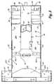
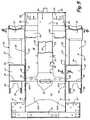
- FIG. 5is a top plan view of the undercarriage transmission assembly
- FIG. 7is a sectional view of the undercarriage transmission taken generally along lines 7 - 7 in FIG. 5 , but shown in a perspective view;
- FIG. 8is a sectional view of a motor mounting flange taken generally along line 8 - 8 in FIG. 4 ;
- FIG. 9is a sectional view taken as on the same line as FIG. 8 showing a drive motor and gear housing in place on the motor mounting flange;
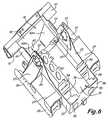
- FIG. 10is a perspective view of a transmission assembly with some drive components installed
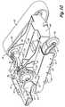
- FIG. 11is a perspective view similar to FIG. 10 , with portions of a main upper frame shown in position with dotted lines, with parts broken away for illustrative purposes;
- FIG. 12is a simplified rear perspective view of a compact loader having a transmission assembly made according to the present disclosure.
- a fully welded track undercarriage transmission assembly illustrated generally at 10includes a central transmission housing or tub 16 .
- the weldment 12 shown in FIG. 3shows the transmission housing or tub 16 , which initially starts with tub half sections 12 and 14 that are formed to have bottom wall sections 18 A and 18 B with formed upright side walls 20 .
- Side walls 20may be integral with the respective bottom wall sections 18 A and 18 B.
- the bottom wall sections 18 A and 18 Bare welded together along a central weld 19 .
- the side wallsinclude an upright motor mounting flange 22 (See FIG. 8 ).
- the side walls 20extend toward the rear of the transmission housing 16 along the length of the transmission housing 16 .
- the bottom wall 18has been formed and the other components are welded in place to form the transmission housing or tub.
- the componentsare welded in a sequence selected for efficient assembly.
- a front end cross wall panel 38is welded to the front edges of side walls 20 and bottom wall 18 .
- Another componentis a central inverted channel 50 that is then welded in place on top of bottom wall 18 in the center of the transmission housing or tub.
- the lower edges of channel side walls 53 extending from a top wall 51 of the inverted channel 50are welded to the bottom wall 18 , along lines 52 , and suitable cross braces or supports 54 , 55 and 56 have ends welded at selected locations for to channel 50 and side walls 20 securing the channel 50 in position between the side walls 20 .
- the supports 54 , 55 , and 56provide support functions and shields for components of the fully assembled loader.
- a rear tub 41is welded in place.
- the rear tub 41has a bottom wall 43 with a center section and inclined side wall sections 43 A.
- the front edge of bottom wall 43including the inclined side wall sections 43 A, are welded to the rear end of the bottom wall 18 .
- Tub 41also has upright side wall sections 44 , and the forward ends of these side wall sections 44 are aligned with and welded to rear ends of the side walls 20 , as well as to the rearwardly extending portions 42 A of reinforcing plates 42 that extend rearwardly of the side walls 20 , (see FIG. 4 ).
- Rear tub 41in turn has a cross member 40 welded to the rear end thereof.
- Cross member 40has an inclined wall welded to tub bottom wall 43 , and has outer side portions 47 that are on the outside of the upright side wall sections 44 and are welded to side wall sections 44 of the transmission housing or tub in the assembly.
- a cross member 46 that is positioned just to the rear of the motor mounting areais welded to the bottom wall 18 , to the interior surfaces of side walls 20 , and to the interior surfaces of the reinforcing plates 42 .
- the weldingcan take place right at the junction between the bottom wall 43 of the rear tub 41 and the bottom wall 18 , as well as right at the junctions with the rear ends of the side walls 20 so the cross member 46 is welded to the front edges of bottom wall 43 , including forward edges of inclined wall sections 43 A, and to side wall sections 44 .
- the cross member 46is also welded to the rear ends of the side walls 53 and the top wall 51 of the channel 50 .
- the cross member 46can be used for mounting the engine and various components used with a finished loader.
- Each track frame 24can be welded together as subassemblies.
- Each track frame 24is made of an inverted channel shape 26 , as can be seen in FIG. 7 , including an upper wall 27 , and a divider wall 28 that welded to the side walls 29 on the interior of the inverted channel 26 .
- the channel 26 of each track frame of podhas horizontal longitudinal plates forming spacers 30 that are welded to the side wall 29 of the inverted channel 26 , and which will be welded against the respective transmission housing side wall 20 .
- the horizontal plates or spacers 30can be legs of a channel or separate plates.
- the top wall of the channelis notched, and a pair of spaced, upright gussets or gusset braces 34 are welded to the top of the side walls 29 of the channel that are exposed by the notch where top wall 27 of inverted channel 26 is cut away.
- Channel braces 32are provided and welded at the front end of the channel 26 .
- a sloping brace plate or reinforcing wall 37is positioned between the gussets 34 on each channel 26 and is weld to the gussets.
- the brace plate of reinforcing wall 37has an integral upright flange 35 that is a portion of the race plate or reinforcing wall 37 is made so it will contact the respective side wall 20 of the transmission housing when the track frames or pods are welded in place.
- the upright flange 35will extend up along the motor mounting flange 22 about half way up the opening 23 for the drive motor when the track frame is welded to the side wall 20
- the reinforcing wall or brace plate 37 of each track frame or podalso has a lower flange 39 , shown in dotted lines in FIGS. 4 and 7 that welds to the outer leg 29 of the respective track frame.
- the track frames or podscan be welded as separate right and left subassemblies to the side walls 20 of the central transmission housing or tub 16 .
- the edges of the spacers 30are welded full length to the respective side wall 20 .
- the gussets 34are welded to the respective side wall 20 and the rear gusset 34 is welded to the aligning side wall section 44 of the rear tub 41 .
- the upright flanges 35are welded in place at the lower portion of the motor mounting flanges 22 .
- Each flange 35has a recess 33 that aligns with a lower half of opening 23 and has holes aligning with bolt holes in the motor mounting flange 22 for bolts or capscrews that hold the motors in place on each side of the transmission housing.
- a reinforcing plate 42is welded to each of the motor mounting flanges 22 on the interior of the motor mounting flanges.
- the reinforcement plates 42have openings aligning with the openings 23 for the motors and also have bolt holes for mounting the motors.
- channel-shaped members 26for forming the track frames or pods 24 provides lower side wall portions of side walls 29 , below the cross wall 28 , for mounting bogie wheels 66 ( FIGS. 10 and 11 )
- the space above the wall 28 in each track frame 24is used for mounting track tensioners 60 , as shown in FIG. 10 .
- FIG. 11is a schematic perspective view of the undercarriage transmission assembly 10 , further assembled to show other machine components in place for illustrative purposes.
- FIG. 12is a simplified rear perspective view of a compact loader using the fully welded transmission housing as a main frame.
- the track frame or pod 24 on each side of the transmission assemblyis provided with a front tensioning roller 60 which is mounted on a suitable spring loaded slide arm 62 .
- a rear idler roller 64is mounted on the side walls 29 of the track frame channel 26 , below cross wall 28 .
- the bogie wheels 66are mounted in the lower mounting slots in side walls 29 of the track frame channel 26 .
- a track 68is illustrated on the undercarriage transmission assembly 10 in FIGS.
- the drive sprocket 70 on each side of the transmission housingis drivably mounted on an output shaft of a motor assembly 73 that includes gear housing section 72 that is part of the motor assembly 73 and is driven by a respective hydraulic drive motor section 74 of the motor assembly.
- the motor assembly 73is shown in position on the motor mounting flange 22 in FIG. 8 .
- the hydraulic drive motor sections 74are on the interior side of the mounting flanges 22 , and reinforcement plates 42 so that the motor sections 74 are on the interior of the undercarriage transmission assembly.
- the motor assembliesare mounted from the outside of the walls 20 by passing the motor sections through the openings 23 of the motor mounting flanges and then the flanges on the gear housing sections 72 are attached with mounting bolts or capscrews or other suitable fasteners.
- the motor sections 74thus do not extend outwardly from the side plates 20 of the transmission housing 16 .
- the mounting bolts or capscrews holding the motor assembliesalso will clamp the side panels or plates 82 of a main upper frame 80 onto the motor mounting flanges 22 , as shown fragmentarily in FIG. 11 .
- the main frame 80is shown in dotted lines in FIG. 11 and is a separate weldment that has the side panels or plates 82 and upright supports 84 ( FIG. 12 ) that can be used for mounting lift arms 85 for a small loader 86 .
- the side plates 82 of the main frameare formed to provide a material layer or plate portion on the exterior of the side walls 20 along an upper part of the motor mounting flange 22 , (upper half of the motor) above the flange 35 and gussets 34 .
- side plates 82are recessed as at 81 to form motor openings aligning with for openings 23 where the side plates 82 mate with the exterior of the motor mounting flanges 22 .
- the portions of the side plates 82 that align with the motor mounting flangesare positioned above and are the same thickness as flanges 35 of the reinforcing wall 37 .
- the upper edges of the flanges 35meet the lower edges of the side plates 82 at the motor mounting flanges 22 as shown at line 83 in FIG. 8 .
- the side panels or plates 82 of the main frame 80are clamped against the upper part of motor mounting flanges 22 of side walls 20 when the motors are secured.
- the motor mounting flanges 22 , the reinforcing plates 42 , the main frame side plates 82 , and, below the side plates 82 , the flanges 35as shown in FIGS.
- motor support platesfor rigidity and strength.
- the motor support platesare braced back to the track frames or pods 24 with the gussets 34 , the inclined walls or brace plates 37 and the flanges or brace plate portions 35 and 39 on the walls or brace plates 37 .
- suitable hydraulic lines 90are protected by being on the interior of the side walls 20 of the transmission housing 16 and they are also easily connected to hydraulic connections such as a pump 92 , through valves 94 .
- the pump 92is driven from an engine represented only schematically at 96 .
- the engine 96provides the power for the track driven machine.
- the undercarriage transmission assembly weldment 10including the welded on track frames or pods, provides for a narrower overall frame, by avoiding the need for any additional bolt on spacers or cross members relative to the center transmission housing 16 .
- the welded track pods and transmission housingprovide great rigidity and strength.
- the mounting of the drive motor sections 74 on the interior of the transmission housing 16that is, on the inside of side walls 20 , also reduces the overall width necessary to accommodate drive components.
- the single weldment of the undercarriage transmission assembly that is made prior to the assembly of the other components, such as motors, bogies, controls the upper main frame member and tracks that are shown partially in FIGS. 11 and 12makes overall machine assembly time less because there are fewer bolted on parts and components.
- the track framesare not bolted on the central transmission housing or tub.
- the ability to have reinforced or sandwiched flanges or flange plates for bolting on the motorsprovides a rigid mounting to withstand the loads on the drive motors encountered when driving the tracks.
Landscapes
- Engineering & Computer Science (AREA)
- Mechanical Engineering (AREA)
- Structural Engineering (AREA)
- Chemical & Material Sciences (AREA)
- Combustion & Propulsion (AREA)
- Transportation (AREA)
- Civil Engineering (AREA)
- General Engineering & Computer Science (AREA)
- Architecture (AREA)
- Mining & Mineral Resources (AREA)
- Body Structure For Vehicles (AREA)
- General Details Of Gearings (AREA)
- Connection Of Plates (AREA)
Abstract
Description
Claims (20)
Priority Applications (6)
| Application Number | Priority Date | Filing Date | Title |
|---|---|---|---|
| US12/251,555US7815000B2 (en) | 2008-10-15 | 2008-10-15 | Fully welded track undercarriage transmission with inboard motor mounting flange |
| CN2009801403702ACN102177298B (en) | 2008-10-15 | 2009-10-12 | Fully welded track undercarriage transmission with inboard motor mounting flange |
| CA2739616ACA2739616A1 (en) | 2008-10-15 | 2009-10-12 | Fully welded track undercarriage transmission with inboard motor mounting flange |
| ES09736769.2TES2677598T3 (en) | 2008-10-15 | 2009-10-12 | Fully welded track type lower train transmission with inner engine mounting wing |
| EP09736769.2AEP2350398B1 (en) | 2008-10-15 | 2009-10-12 | Fully welded track undercarriage transmission with inboard motor mounting flange |
| PCT/US2009/060325WO2010045136A1 (en) | 2008-10-15 | 2009-10-12 | Fully welded track undercarriage transmission with inboard motor mounting flange |
Applications Claiming Priority (1)
| Application Number | Priority Date | Filing Date | Title |
|---|---|---|---|
| US12/251,555US7815000B2 (en) | 2008-10-15 | 2008-10-15 | Fully welded track undercarriage transmission with inboard motor mounting flange |
Publications (2)
| Publication Number | Publication Date |
|---|---|
| US20100089668A1 US20100089668A1 (en) | 2010-04-15 |
| US7815000B2true US7815000B2 (en) | 2010-10-19 |
Family
ID=41337088
Family Applications (1)
| Application Number | Title | Priority Date | Filing Date |
|---|---|---|---|
| US12/251,555ActiveUS7815000B2 (en) | 2008-10-15 | 2008-10-15 | Fully welded track undercarriage transmission with inboard motor mounting flange |
Country Status (6)
| Country | Link |
|---|---|
| US (1) | US7815000B2 (en) |
| EP (1) | EP2350398B1 (en) |
| CN (1) | CN102177298B (en) |
| CA (1) | CA2739616A1 (en) |
| ES (1) | ES2677598T3 (en) |
| WO (1) | WO2010045136A1 (en) |
Cited By (10)
| Publication number | Priority date | Publication date | Assignee | Title |
|---|---|---|---|---|
| US20140041956A1 (en)* | 2012-08-10 | 2014-02-13 | Komatsu Ltd. | Bulldozer |
| US8820453B2 (en) | 2012-11-30 | 2014-09-02 | Caterpillar Sarl | Bumper assembly |
| US20140360811A1 (en)* | 2013-06-10 | 2014-12-11 | Custom Truck & Equipment LLC | Tracked Undercarriage Adapted For Modular Reconfiguration |
| US20150021893A1 (en)* | 2013-07-22 | 2015-01-22 | GM Global Technology Operations LLC | Center tunnel integrated truss architecture |
| US20160152294A1 (en)* | 2014-11-28 | 2016-06-02 | Samsung Sdi Co., Ltd. | Frame for bike and electric bike having the same |
| US9650088B2 (en) | 2012-12-06 | 2017-05-16 | Cnh Industrial America Llc | Work vehicle |
| US10494041B2 (en) | 2015-04-29 | 2019-12-03 | Clark Equipment Company | Apparatus for mounting a track frame to a frame of a power machine |
| US10858803B2 (en) | 2017-04-19 | 2020-12-08 | Clark Equipment Company | Loader frame |
| US11208786B2 (en) | 2019-07-29 | 2021-12-28 | Great Plains Manufacturing, Inc. | Loader arm connection assembly for compact utility loader |
| US11260921B2 (en) | 2018-10-19 | 2022-03-01 | Clark Equipment Company | Rigid track mount |
Families Citing this family (3)
| Publication number | Priority date | Publication date | Assignee | Title |
|---|---|---|---|---|
| US8299127B2 (en)* | 2009-03-11 | 2012-10-30 | Conopco, Inc. | Method and composition for evenly applying water soluble actives |
| EP2978656B1 (en)* | 2013-03-25 | 2016-11-16 | Polaris Industries Inc. | Tracked all-terrain vehicle |
| CN109292016A (en)* | 2018-09-10 | 2019-02-01 | 陕西斯达防爆安全科技股份有限公司 | A kind of drilling machine entire track vehicle frame |
Citations (48)
| Publication number | Priority date | Publication date | Assignee | Title |
|---|---|---|---|---|
| US2002474A (en) | 1932-05-06 | 1935-05-21 | Int Harvester Co | Frame for track type tractors |
| US3085643A (en) | 1959-06-15 | 1963-04-16 | Eimco Corp | Endless tread vehicle having a pump mounted thereon |
| US3129780A (en) | 1961-04-11 | 1964-04-21 | William I Uyehara | Wheeled tractor construction |
| US3635365A (en) | 1969-02-20 | 1972-01-18 | Clark Equipment Co | Tractor vehicle with hydrostatic drive means |
| US3767254A (en) | 1969-09-11 | 1973-10-23 | Int Harvester Co | Tractor body with integral upright a-frame |
| US3910367A (en) | 1974-05-10 | 1975-10-07 | Fiat Allis Construct Machine | Crawler tractor oscillating beam mounting |
| US4055262A (en) | 1976-02-02 | 1977-10-25 | Clark Equipment Company | Loader main frame for skid steer loader |
| US4060261A (en) | 1976-02-02 | 1977-11-29 | Clark Equipment Company | Loader main frame for skid steer loader |
| US4074782A (en) | 1976-02-02 | 1978-02-21 | Clark Equipment Company | Hydraulic system of a skid steer loader |
| US4150474A (en) | 1976-02-02 | 1979-04-24 | Clark Equipment Company | Method of manufacturing an overhead guard for a skid steer loader |
| US4168757A (en) | 1978-02-21 | 1979-09-25 | Clark Equipment Company | Drive system for a skid steer loader |
| US4186812A (en) | 1977-07-07 | 1980-02-05 | Caterpillar Tractor Co. | Equalizer bar support assembly |
| US4359116A (en) | 1980-01-21 | 1982-11-16 | Standard Manufacturing Company, Incorporated | Ground pressure reducing undercarriage unit |
| FR2591987A1 (en) | 1985-12-19 | 1987-06-26 | Bourg Claude | Carrier on caterpillar tracks with variable geometry |
| JPS62261580A (en) | 1986-05-07 | 1987-11-13 | Iseki & Co Ltd | Track-to-rut distance expansion/reduction device for crawler-type vehicles |
| US4815550A (en) | 1987-08-21 | 1989-03-28 | Clark Equipment Company | Engine cooling system for skid steer loaders |
| US4955455A (en) | 1987-08-21 | 1990-09-11 | Clark Equipment Company | Method for assembling a skid steer loader |
| US4962825A (en) | 1987-08-21 | 1990-10-16 | Clark Equipment Company | Skid steer loader |
| US4962821A (en) | 1989-03-22 | 1990-10-16 | Daewoo Heavy Industries Ltd. | Discrete drive system for a skid steer loader |
| US5568841A (en)* | 1993-12-03 | 1996-10-29 | O&K Orenstein & Koppel Aktiengesellschaft | Rear frame for center pivot steered construction machinery |
| US5894908A (en)* | 1997-05-07 | 1999-04-20 | Caterpillar Inc. | Unitary frame structure |
| US6098739A (en) | 1998-06-05 | 2000-08-08 | Caterpillar S.A.R.L. | Main frame assembly |
| US6108907A (en) | 1998-06-05 | 2000-08-29 | Caterpillar S.A.R.L. | Method of assembling a work machine |
| US6401847B1 (en) | 1996-11-08 | 2002-06-11 | Case Corporation | Vehicle track undercarriage adjustment system |
| US6425453B1 (en) | 2000-12-08 | 2002-07-30 | Clark Equipment Company | Transmission on all wheel steer power machine |
| US6446744B2 (en) | 1998-12-23 | 2002-09-10 | Bombardier Inc. | Engine cradle for a vehicle |
| US6604600B2 (en) | 2000-11-06 | 2003-08-12 | Bombardier Inc. | Method for assembling a vehicle |
| US20030205424A1 (en) | 2002-05-01 | 2003-11-06 | Case Corporation, A Delaware Corporation | Skid steer loader |
| US6655482B2 (en) | 2001-12-21 | 2003-12-02 | Caterpillar Inc | Drive assembly for a track-type machine |
| JP2004017705A (en) | 2002-06-13 | 2004-01-22 | Komatsu Ltd | Main frame of work vehicle |
| US6719075B2 (en)* | 2000-08-15 | 2004-04-13 | Komatsu Ltd. | Frame structure of crawler-type construction machine vehicle |
| US6742619B2 (en) | 2001-10-03 | 2004-06-01 | Trelleborg Ab | Engine mounts, such as for a skid steer loader, having internally snubbed shocks and vibration isolators, and a method of making the engine mounts |
| US6786289B2 (en) | 2002-05-10 | 2004-09-07 | Case Corporation | Skid steer vehicle with direct drive |
| US6823961B2 (en) | 2002-05-01 | 2004-11-30 | Cnh America Llc | Skid steer vehicle with axle housing having a double gear reduction |
| US20040239092A1 (en) | 2003-04-14 | 2004-12-02 | Haringer Alois Johann | Crawler-tracked vehicle with variable track width |
| US6832659B1 (en)* | 2001-11-01 | 2004-12-21 | Clark Equipment Company | Loader frame and bolt-on track drive |
| US6902027B2 (en)* | 2001-02-21 | 2005-06-07 | Komatsu Ltd. | Piping structure of crawler driving hydraulic motor |
| WO2005054043A1 (en) | 2003-11-25 | 2005-06-16 | Clark Equipment Company | Drive track support with vibration isolation |
| US20050167969A1 (en) | 2004-01-29 | 2005-08-04 | Kazumasa Fukazawa | Structure of main frame for construction machines and method of manufacturing the same |
| US6926105B2 (en) | 2003-09-10 | 2005-08-09 | Glen Brazier | Chassis supported track assembly |
| US7000724B2 (en) | 2003-08-28 | 2006-02-21 | Cnh America Llc | Skid steer vehicle with bogie suspension |
| US7036622B2 (en) | 2001-04-11 | 2006-05-02 | Koji Iwaki | Tractor frame and method of manufacture therefor |
| US7044258B2 (en) | 2002-04-05 | 2006-05-16 | Cnh America Llc | Direct drive suspension |
| US7059434B2 (en)* | 2003-07-14 | 2006-06-13 | Clark Equipment Company | Hand controls for small loader |
| US7156200B2 (en) | 2001-04-19 | 2007-01-02 | Caterpillar S.A.R.L. | Main frame for a tracked skid steer loader machine |
| US7182369B2 (en)* | 2000-05-11 | 2007-02-27 | Jlg Omniquip, Inc. | Modular frame load handler with translatable carriage |
| EP1811089A2 (en) | 2006-01-20 | 2007-07-25 | JCB Compact Products Limited | Working machine |
| US7401673B2 (en)* | 2005-09-15 | 2008-07-22 | Komatsu Ltd. | Frame structure for construction machine |
Family Cites Families (2)
| Publication number | Priority date | Publication date | Assignee | Title |
|---|---|---|---|---|
| UST966007I4 (en)* | 1977-07-07 | 1978-01-03 | Caterpillar Tractor Co. | Main frame for a loader vehicle |
| US5701662A (en)* | 1995-11-06 | 1997-12-30 | Matsushita Electric Industrial Co., Ltd. | Axial type electronic component inserting apparatus |
- 2008
- 2008-10-15USUS12/251,555patent/US7815000B2/enactiveActive
- 2009
- 2009-10-12EPEP09736769.2Apatent/EP2350398B1/enactiveActive
- 2009-10-12CNCN2009801403702Apatent/CN102177298B/enactiveActive
- 2009-10-12CACA2739616Apatent/CA2739616A1/ennot_activeAbandoned
- 2009-10-12WOPCT/US2009/060325patent/WO2010045136A1/enactiveApplication Filing
- 2009-10-12ESES09736769.2Tpatent/ES2677598T3/enactiveActive
Patent Citations (54)
| Publication number | Priority date | Publication date | Assignee | Title |
|---|---|---|---|---|
| US2002474A (en) | 1932-05-06 | 1935-05-21 | Int Harvester Co | Frame for track type tractors |
| US3085643A (en) | 1959-06-15 | 1963-04-16 | Eimco Corp | Endless tread vehicle having a pump mounted thereon |
| US3129780A (en) | 1961-04-11 | 1964-04-21 | William I Uyehara | Wheeled tractor construction |
| US3635365A (en) | 1969-02-20 | 1972-01-18 | Clark Equipment Co | Tractor vehicle with hydrostatic drive means |
| US3767254A (en) | 1969-09-11 | 1973-10-23 | Int Harvester Co | Tractor body with integral upright a-frame |
| US3910367A (en) | 1974-05-10 | 1975-10-07 | Fiat Allis Construct Machine | Crawler tractor oscillating beam mounting |
| US4055262A (en) | 1976-02-02 | 1977-10-25 | Clark Equipment Company | Loader main frame for skid steer loader |
| US4060261A (en) | 1976-02-02 | 1977-11-29 | Clark Equipment Company | Loader main frame for skid steer loader |
| US4074782A (en) | 1976-02-02 | 1978-02-21 | Clark Equipment Company | Hydraulic system of a skid steer loader |
| US4150474A (en) | 1976-02-02 | 1979-04-24 | Clark Equipment Company | Method of manufacturing an overhead guard for a skid steer loader |
| US4186812A (en) | 1977-07-07 | 1980-02-05 | Caterpillar Tractor Co. | Equalizer bar support assembly |
| US4168757A (en) | 1978-02-21 | 1979-09-25 | Clark Equipment Company | Drive system for a skid steer loader |
| US4359116A (en) | 1980-01-21 | 1982-11-16 | Standard Manufacturing Company, Incorporated | Ground pressure reducing undercarriage unit |
| FR2591987A1 (en) | 1985-12-19 | 1987-06-26 | Bourg Claude | Carrier on caterpillar tracks with variable geometry |
| JPS62261580A (en) | 1986-05-07 | 1987-11-13 | Iseki & Co Ltd | Track-to-rut distance expansion/reduction device for crawler-type vehicles |
| US4815550A (en) | 1987-08-21 | 1989-03-28 | Clark Equipment Company | Engine cooling system for skid steer loaders |
| US4955455A (en) | 1987-08-21 | 1990-09-11 | Clark Equipment Company | Method for assembling a skid steer loader |
| US4962825A (en) | 1987-08-21 | 1990-10-16 | Clark Equipment Company | Skid steer loader |
| US4962821A (en) | 1989-03-22 | 1990-10-16 | Daewoo Heavy Industries Ltd. | Discrete drive system for a skid steer loader |
| US5568841A (en)* | 1993-12-03 | 1996-10-29 | O&K Orenstein & Koppel Aktiengesellschaft | Rear frame for center pivot steered construction machinery |
| US6401847B1 (en) | 1996-11-08 | 2002-06-11 | Case Corporation | Vehicle track undercarriage adjustment system |
| US5894908A (en)* | 1997-05-07 | 1999-04-20 | Caterpillar Inc. | Unitary frame structure |
| US6205665B1 (en) | 1998-06-05 | 2001-03-27 | Caterpillar S.A.R.L. | Main frame assembly |
| US6108907A (en) | 1998-06-05 | 2000-08-29 | Caterpillar S.A.R.L. | Method of assembling a work machine |
| US6098739A (en) | 1998-06-05 | 2000-08-08 | Caterpillar S.A.R.L. | Main frame assembly |
| US6446744B2 (en) | 1998-12-23 | 2002-09-10 | Bombardier Inc. | Engine cradle for a vehicle |
| US7390021B2 (en)* | 2000-05-11 | 2008-06-24 | Jlg Omniquip, Inc. | Modular frame load handler with translatable boom carriage |
| US7182369B2 (en)* | 2000-05-11 | 2007-02-27 | Jlg Omniquip, Inc. | Modular frame load handler with translatable carriage |
| US6719075B2 (en)* | 2000-08-15 | 2004-04-13 | Komatsu Ltd. | Frame structure of crawler-type construction machine vehicle |
| US6604600B2 (en) | 2000-11-06 | 2003-08-12 | Bombardier Inc. | Method for assembling a vehicle |
| US6651768B2 (en) | 2000-11-06 | 2003-11-25 | Bombardier Inc. | Snowmobile engine mount |
| US6425453B1 (en) | 2000-12-08 | 2002-07-30 | Clark Equipment Company | Transmission on all wheel steer power machine |
| US6513614B2 (en) | 2000-12-08 | 2003-02-04 | Clark Equipment Company | Transmission on all wheel steer power machine |
| US6902027B2 (en)* | 2001-02-21 | 2005-06-07 | Komatsu Ltd. | Piping structure of crawler driving hydraulic motor |
| US7036622B2 (en) | 2001-04-11 | 2006-05-02 | Koji Iwaki | Tractor frame and method of manufacture therefor |
| US7156200B2 (en) | 2001-04-19 | 2007-01-02 | Caterpillar S.A.R.L. | Main frame for a tracked skid steer loader machine |
| US6742619B2 (en) | 2001-10-03 | 2004-06-01 | Trelleborg Ab | Engine mounts, such as for a skid steer loader, having internally snubbed shocks and vibration isolators, and a method of making the engine mounts |
| US6832659B1 (en)* | 2001-11-01 | 2004-12-21 | Clark Equipment Company | Loader frame and bolt-on track drive |
| US6655482B2 (en) | 2001-12-21 | 2003-12-02 | Caterpillar Inc | Drive assembly for a track-type machine |
| US7044258B2 (en) | 2002-04-05 | 2006-05-16 | Cnh America Llc | Direct drive suspension |
| US20030205424A1 (en) | 2002-05-01 | 2003-11-06 | Case Corporation, A Delaware Corporation | Skid steer loader |
| US6823961B2 (en) | 2002-05-01 | 2004-11-30 | Cnh America Llc | Skid steer vehicle with axle housing having a double gear reduction |
| US6786289B2 (en) | 2002-05-10 | 2004-09-07 | Case Corporation | Skid steer vehicle with direct drive |
| JP2004017705A (en) | 2002-06-13 | 2004-01-22 | Komatsu Ltd | Main frame of work vehicle |
| US20040239092A1 (en) | 2003-04-14 | 2004-12-02 | Haringer Alois Johann | Crawler-tracked vehicle with variable track width |
| US7059434B2 (en)* | 2003-07-14 | 2006-06-13 | Clark Equipment Company | Hand controls for small loader |
| US7000724B2 (en) | 2003-08-28 | 2006-02-21 | Cnh America Llc | Skid steer vehicle with bogie suspension |
| US6926105B2 (en) | 2003-09-10 | 2005-08-09 | Glen Brazier | Chassis supported track assembly |
| WO2005054043A1 (en) | 2003-11-25 | 2005-06-16 | Clark Equipment Company | Drive track support with vibration isolation |
| US20060001250A1 (en) | 2004-01-29 | 2006-01-05 | Kazumasa Fukazawa | Main frame for construction machines and method of manufacturing the same |
| EP1710357A1 (en) | 2004-01-29 | 2006-10-11 | Komatsu Ltd | Main frame of construction machine and method of producing the same |
| US20050167969A1 (en) | 2004-01-29 | 2005-08-04 | Kazumasa Fukazawa | Structure of main frame for construction machines and method of manufacturing the same |
| US7401673B2 (en)* | 2005-09-15 | 2008-07-22 | Komatsu Ltd. | Frame structure for construction machine |
| EP1811089A2 (en) | 2006-01-20 | 2007-07-25 | JCB Compact Products Limited | Working machine |
Non-Patent Citations (3)
| Title |
|---|
| Liehr, Douglas et al.: United States Defensive Publication No. T966,007 (was not accepted as a Publication on this form when entering it)-Jan. 3, 1978. Main Frame for Loader Vehicle. |
| Notification of International Search Report dated Dec. 16, 2009 for Int'l Appln. No. PCT/US2009/060325 (EPO). |
| Written Opinion of the Int'l Searching Authority dated Dec. 16, 2009 for PCT/US2009/060325 (EPO). |
Cited By (26)
| Publication number | Priority date | Publication date | Assignee | Title |
|---|---|---|---|---|
| US8899371B2 (en)* | 2012-08-10 | 2014-12-02 | Komatsu Ltd. | Bulldozer |
| US20140041956A1 (en)* | 2012-08-10 | 2014-02-13 | Komatsu Ltd. | Bulldozer |
| US8820453B2 (en) | 2012-11-30 | 2014-09-02 | Caterpillar Sarl | Bumper assembly |
| US9650088B2 (en) | 2012-12-06 | 2017-05-16 | Cnh Industrial America Llc | Work vehicle |
| US20140360811A1 (en)* | 2013-06-10 | 2014-12-11 | Custom Truck & Equipment LLC | Tracked Undercarriage Adapted For Modular Reconfiguration |
| US9434586B2 (en)* | 2013-06-10 | 2016-09-06 | Custom Truck & Equipment LLC | Tracked undercarriage adapted for modular reconfiguration |
| US20150021893A1 (en)* | 2013-07-22 | 2015-01-22 | GM Global Technology Operations LLC | Center tunnel integrated truss architecture |
| US9248860B2 (en)* | 2013-07-22 | 2016-02-02 | GM Global Technology Operations LLC | Center tunnel integrated truss architecture |
| US20160152294A1 (en)* | 2014-11-28 | 2016-06-02 | Samsung Sdi Co., Ltd. | Frame for bike and electric bike having the same |
| US9969455B2 (en)* | 2014-11-28 | 2018-05-15 | Samsung Sdi Co., Ltd. | Frame for bike and electric bike having the same |
| US10494041B2 (en) | 2015-04-29 | 2019-12-03 | Clark Equipment Company | Apparatus for mounting a track frame to a frame of a power machine |
| US10858803B2 (en) | 2017-04-19 | 2020-12-08 | Clark Equipment Company | Loader frame |
| US11530523B2 (en) | 2017-04-19 | 2022-12-20 | Clark Equipment Company | Loader frame |
| US11260921B2 (en) | 2018-10-19 | 2022-03-01 | Clark Equipment Company | Rigid track mount |
| US11208786B2 (en) | 2019-07-29 | 2021-12-28 | Great Plains Manufacturing, Inc. | Loader arm connection assembly for compact utility loader |
| US11549232B2 (en) | 2019-07-29 | 2023-01-10 | Great Plains Manufacturing, Inc. | Vertical lift loader arms for compact utility loader |
| US11649605B2 (en) | 2019-07-29 | 2023-05-16 | Great Plains Manufacturing, Inc. | Engine mount for compact utility loader |
| US11692328B2 (en) | 2019-07-29 | 2023-07-04 | Great Plains Manufacturing, Inc. | Compact utility loader |
| US11788250B2 (en) | 2019-07-29 | 2023-10-17 | Great Plains Manufacturing, Inc. | Loader with improved arm path |
| US11885095B1 (en) | 2019-07-29 | 2024-01-30 | Great Plains Manufacturing, Inc. | Loader with improved arm path |
| US12000107B1 (en) | 2019-07-29 | 2024-06-04 | Great Plains Manufacturing, Inc. | Loader with improved arm path |
| US12104348B1 (en) | 2019-07-29 | 2024-10-01 | Great Plains Manufacturing, Inc. | Loader with improved arm path |
| US12123161B1 (en) | 2019-07-29 | 2024-10-22 | Great Plains Manufacturing, Inc. | Loader with improved arm path |
| US12173468B2 (en) | 2019-07-29 | 2024-12-24 | Great Plains Manufacturing, Inc. | Control system for compact utility loader |
| US12203236B1 (en) | 2019-07-29 | 2025-01-21 | Great Plains Manufacturing, Inc. | Loader with improved arm path |
| US12325971B1 (en) | 2019-07-29 | 2025-06-10 | Great Plains Manufacturing, Inc. | Loader with improved arm path |
Also Published As
| Publication number | Publication date |
|---|---|
| CN102177298A (en) | 2011-09-07 |
| EP2350398A1 (en) | 2011-08-03 |
| CA2739616A1 (en) | 2010-04-22 |
| EP2350398B1 (en) | 2018-04-25 |
| ES2677598T3 (en) | 2018-08-03 |
| CN102177298B (en) | 2013-08-28 |
| WO2010045136A1 (en) | 2010-04-22 |
| US20100089668A1 (en) | 2010-04-15 |
Similar Documents
| Publication | Publication Date | Title |
|---|---|---|
| US7815000B2 (en) | Fully welded track undercarriage transmission with inboard motor mounting flange | |
| US8016065B2 (en) | Split chaincase with fixed axles | |
| JP4265723B2 (en) | Frame structure of crawler type construction machine vehicle | |
| US20070062742A1 (en) | Structure of main frame for construction machines and method of manufacturing the same | |
| US7802815B2 (en) | Working machine | |
| EP1033448A2 (en) | Excavator frame and method of assembly | |
| CN103538646A (en) | Tandem housing | |
| US20140151142A1 (en) | Vehicle and Method for Mounting a Drive Assembly | |
| EP1811090A2 (en) | Working machine | |
| KR102616433B1 (en) | Frame extension module and truck including the same | |
| US10919586B2 (en) | Vehicle shipping position to application position conversion | |
| US10822034B2 (en) | Plate steel constructed frame for self propelled sprayers | |
| US20040146354A1 (en) | Two-piece main frame assembly for paving vehicles | |
| CN209776545U (en) | Vehicle lower structure | |
| CN210191673U (en) | Riding wheel seat with auxiliary fixing device and crawler device | |
| JP4215460B2 (en) | Crawler link | |
| RU2593288C2 (en) | Main frame and machine with said main frame | |
| JPH0515188Y2 (en) | ||
| KR20040031248A (en) | Bus frame structure for using decking method | |
| CN209776548U (en) | vehicle substructure | |
| JPH0626471Y2 (en) | Semi-endless crawler | |
| SE2351283A1 (en) | Chainsaw guide bar comprising plastic inserts and method of manufacturing the same | |
| JP2562946Y2 (en) | Car body for undercarriage of construction machinery | |
| KR100426459B1 (en) | Passenger conveyor | |
| JPS6314602Y2 (en) |
Legal Events
| Date | Code | Title | Description |
|---|---|---|---|
| AS | Assignment | Owner name:CLARK EQUIPMENT COMPANY,NORTH DAKOTA Free format text:ASSIGNMENT OF ASSIGNORS INTEREST;ASSIGNORS:KISSE, BRANDON J.;WALETZKO, ROBERT D.;BARES, MARK F.;SIGNING DATES FROM 20081013 TO 20081015;REEL/FRAME:021683/0335 Owner name:CLARK EQUIPMENT COMPANY, NORTH DAKOTA Free format text:ASSIGNMENT OF ASSIGNORS INTEREST;ASSIGNORS:KISSE, BRANDON J.;WALETZKO, ROBERT D.;BARES, MARK F.;SIGNING DATES FROM 20081013 TO 20081015;REEL/FRAME:021683/0335 | |
| STCF | Information on status: patent grant | Free format text:PATENTED CASE | |
| AS | Assignment | Owner name:HSBC BANK PLC, UNITED KINGDOM Free format text:SECURITY AGREEMENT;ASSIGNOR:CLARK EQUIPMENT COMPANY;REEL/FRAME:025453/0714 Effective date:20101208 | |
| CC | Certificate of correction | ||
| AS | Assignment | Owner name:CLARK EQUIPMENT COMPANY, NORTH DAKOTA Free format text:RELEASE BY SECURED PARTY;ASSIGNOR:HSBC BANK PLC;REEL/FRAME:028848/0288 Effective date:20120808 | |
| FPAY | Fee payment | Year of fee payment:4 | |
| AS | Assignment | Owner name:JPMORGAN CHASE BANK, N.A., AS ADMINISTRATIVE AGENT Free format text:PATENT SECURITY AGREEMENT-ABL;ASSIGNORS:DOOSAN INFRACORE INTERNATIONAL, INC.;CLARK EQUIPMENT COMPANY;REEL/FRAME:033085/0873 Effective date:20140528 Owner name:JPMORGAN CHASE BANK, N.A., AS ADMINISTRATIVE AGENT Free format text:PATENT SECURITY AGREEMENT-TERM LOAN;ASSIGNORS:DOOSAN INFRACORE INTERNATIONAL, INC.;CLARK EQUIPMENT COMPANY;REEL/FRAME:033085/0916 Effective date:20140528 | |
| AS | Assignment | Owner name:CLARK EQUIPMENT COMPANY, DELAWARE Free format text:MERGER;ASSIGNORS:DOOSAN INFRACORE INTERNATIONAL, INC.;CLARK EQUIPMENT COMPANY;REEL/FRAME:042500/0899 Effective date:20160630 | |
| AS | Assignment | Owner name:CLARK EQUIPMENT COMPANY, DELAWARE Free format text:RELEASE OF PATENT SECURITY AGREEMENT-ABL;ASSIGNOR:JPMORGAN CHASE BANK, N.A., AS ADMINISTRATIVE AGENT;REEL/FRAME:042563/0747 Effective date:20170518 Owner name:CLARK EQUIPMENT COMPANY, DELAWARE Free format text:RELEASE OF PATENT SECURITY AGREEMENT-TERM LOAN;ASSIGNOR:JPMORGAN CHASE BANK, N.A., AS ADMINISTRATIVE AGENT;REEL/FRAME:042563/0801 Effective date:20170518 | |
| AS | Assignment | Owner name:BANK OF AMERICA, N.A., AS ADMINISTRATIVE AGENT, NE Free format text:PATENT SECURITY AGREEMENT (ABL);ASSIGNOR:CLARK EQUIPMENT COMPANY;REEL/FRAME:042583/0886 Effective date:20170518 Owner name:BANK OF AMERICA, N.A., AS ADMINISTRATIVE AGENT, NE Free format text:PATENT SECURITY AGREEMENT (TERM LOAN);ASSIGNOR:CLARK EQUIPMENT COMPANY;REEL/FRAME:042583/0863 Effective date:20170518 Owner name:BANK OF AMERICA, N.A., AS ADMINISTRATIVE AGENT, NEW YORK Free format text:PATENT SECURITY AGREEMENT (ABL);ASSIGNOR:CLARK EQUIPMENT COMPANY;REEL/FRAME:042583/0886 Effective date:20170518 Owner name:BANK OF AMERICA, N.A., AS ADMINISTRATIVE AGENT, NEW YORK Free format text:PATENT SECURITY AGREEMENT (TERM LOAN);ASSIGNOR:CLARK EQUIPMENT COMPANY;REEL/FRAME:042583/0863 Effective date:20170518 | |
| MAFP | Maintenance fee payment | Free format text:PAYMENT OF MAINTENANCE FEE, 8TH YEAR, LARGE ENTITY (ORIGINAL EVENT CODE: M1552) Year of fee payment:8 | |
| AS | Assignment | Owner name:WILMINGTON TRUST, NATIONAL ASSOCIATION, AS COLLATERAL AGENT, MINNESOTA Free format text:PATENT SECURITY AGREEMENT (NOTES);ASSIGNOR:CLARK EQUIPMENT COMPANY;REEL/FRAME:052802/0464 Effective date:20200529 | |
| MAFP | Maintenance fee payment | Free format text:PAYMENT OF MAINTENANCE FEE, 12TH YEAR, LARGE ENTITY (ORIGINAL EVENT CODE: M1553); ENTITY STATUS OF PATENT OWNER: LARGE ENTITY Year of fee payment:12 | |
| AS | Assignment | Owner name:CLARK EQUIPMENT COMPANY, NORTH DAKOTA Free format text:RELEASE OF SECURITY INTEREST IN PATENTS PREVIOUSLY RECORDED AT REEL/FRAME (042583/0863);ASSIGNOR:BANK OF AMERICA, N.A., AS ADMINISTRATIVE AGENT;REEL/FRAME:060110/0065 Effective date:20220420 | |
| AS | Assignment | Owner name:BANK OF AMERICA, N.A., AS ADMINISTRATIVE AGENT, NEW YORK Free format text:SECURITY INTEREST;ASSIGNOR:CLARK EQUIPMENT COMPANY;REEL/FRAME:059841/0543 Effective date:20220420 | |
| AS | Assignment | Owner name:CLARK EQUIPMENT COMPANY, NORTH DAKOTA Free format text:RELEASE BY SECURED PARTY;ASSIGNOR:WILMINGTON TRUST, NATIONAL ASSOCIATION;REEL/FRAME:061365/0517 Effective date:20220624 Owner name:CLARK EQUIPMENT COMPANY, NORTH DAKOTA Free format text:RELEASE OF SECURITY IN PATENTS PREVIOUSLY RECORDED AT REEL/FRAME 042583/0886;ASSIGNOR:BANK OF AMERICA, N.A.;REEL/FRAME:061365/0464 Effective date:20220420 |