US7814635B2 - Method of making a tissue shaping device - Google Patents
Method of making a tissue shaping deviceDownload PDFInfo
- Publication number
- US7814635B2 US7814635B2US11/383,115US38311506AUS7814635B2US 7814635 B2US7814635 B2US 7814635B2US 38311506 AUS38311506 AUS 38311506AUS 7814635 B2US7814635 B2US 7814635B2
- Authority
- US
- United States
- Prior art keywords
- anchor
- distal
- proximal
- connector
- coronary sinus
- Prior art date
- Legal status (The legal status is an assumption and is not a legal conclusion. Google has not performed a legal analysis and makes no representation as to the accuracy of the status listed.)
- Active, expires
Links
Images


Classifications
- A—HUMAN NECESSITIES
- A61—MEDICAL OR VETERINARY SCIENCE; HYGIENE
- A61F—FILTERS IMPLANTABLE INTO BLOOD VESSELS; PROSTHESES; DEVICES PROVIDING PATENCY TO, OR PREVENTING COLLAPSING OF, TUBULAR STRUCTURES OF THE BODY, e.g. STENTS; ORTHOPAEDIC, NURSING OR CONTRACEPTIVE DEVICES; FOMENTATION; TREATMENT OR PROTECTION OF EYES OR EARS; BANDAGES, DRESSINGS OR ABSORBENT PADS; FIRST-AID KITS
- A61F2/00—Filters implantable into blood vessels; Prostheses, i.e. artificial substitutes or replacements for parts of the body; Appliances for connecting them with the body; Devices providing patency to, or preventing collapsing of, tubular structures of the body, e.g. stents
- A61F2/02—Prostheses implantable into the body
- A61F2/24—Heart valves ; Vascular valves, e.g. venous valves; Heart implants, e.g. passive devices for improving the function of the native valve or the heart muscle; Transmyocardial revascularisation [TMR] devices; Valves implantable in the body
- A61F2/2442—Annuloplasty rings or inserts for correcting the valve shape; Implants for improving the function of a native heart valve
- A61F2/2451—Inserts in the coronary sinus for correcting the valve shape
- Y—GENERAL TAGGING OF NEW TECHNOLOGICAL DEVELOPMENTS; GENERAL TAGGING OF CROSS-SECTIONAL TECHNOLOGIES SPANNING OVER SEVERAL SECTIONS OF THE IPC; TECHNICAL SUBJECTS COVERED BY FORMER USPC CROSS-REFERENCE ART COLLECTIONS [XRACs] AND DIGESTS
- Y10—TECHNICAL SUBJECTS COVERED BY FORMER USPC
- Y10T—TECHNICAL SUBJECTS COVERED BY FORMER US CLASSIFICATION
- Y10T29/00—Metal working
- Y10T29/49—Method of mechanical manufacture
- Y10T29/49609—Spring making
- Y—GENERAL TAGGING OF NEW TECHNOLOGICAL DEVELOPMENTS; GENERAL TAGGING OF CROSS-SECTIONAL TECHNOLOGIES SPANNING OVER SEVERAL SECTIONS OF THE IPC; TECHNICAL SUBJECTS COVERED BY FORMER USPC CROSS-REFERENCE ART COLLECTIONS [XRACs] AND DIGESTS
- Y10—TECHNICAL SUBJECTS COVERED BY FORMER USPC
- Y10T—TECHNICAL SUBJECTS COVERED BY FORMER US CLASSIFICATION
- Y10T29/00—Metal working
- Y10T29/49—Method of mechanical manufacture
- Y10T29/49826—Assembling or joining
- Y10T29/49947—Assembling or joining by applying separate fastener
- Y—GENERAL TAGGING OF NEW TECHNOLOGICAL DEVELOPMENTS; GENERAL TAGGING OF CROSS-SECTIONAL TECHNOLOGIES SPANNING OVER SEVERAL SECTIONS OF THE IPC; TECHNICAL SUBJECTS COVERED BY FORMER USPC CROSS-REFERENCE ART COLLECTIONS [XRACs] AND DIGESTS
- Y10—TECHNICAL SUBJECTS COVERED BY FORMER USPC
- Y10T—TECHNICAL SUBJECTS COVERED BY FORMER US CLASSIFICATION
- Y10T29/00—Metal working
- Y10T29/49—Method of mechanical manufacture
- Y10T29/49995—Shaping one-piece blank by removing material
Definitions
- This inventionrelates generally to devices and methods for shaping tissue by deploying one or more devices in body lumens adjacent to the tissue.
- One particular application of the inventionrelates to a treatment for mitral valve regurgitation through deployment of a tissue shaping device in the patient's coronary sinus or great cardiac vein.
- the mitral valveis a portion of the heart that is located between the chambers of the left atrium and the left ventricle. When the left ventricle contracts to pump blood throughout the body, the mitral valve closes to prevent the blood being pumped back into the left atrium. In some patients, whether due to genetic malformation, disease or injury, the mitral valve fails to close properly causing a condition known as regurgitation, whereby blood is pumped into the atrium upon each contraction of the heart muscle. Regurgitation is a serious, often rapidly deteriorating, condition that reduces circulatory efficiency and must be corrected.
- Two of the more common techniques for restoring the function of a damaged mitral valveare to surgically replace the valve with a mechanical valve or to suture a flexible ring around the valve to support it.
- Each of these proceduresis highly invasive because access to the heart is obtained through an opening in the patient's chest.
- Patients with mitral valve regurgitationare often relatively frail thereby increasing the risks associated with such an operation.
- One less invasive approach for aiding the closure of the mitral valveinvolves the placement of a tissue shaping device in the cardiac sinus and vessel that passes adjacent the mitral valve.
- the tissue shaping deviceis designed to push the vessel and surrounding tissue against the valve to aid its closure.
- This techniquehas the advantage over other methods of mitral valve repair because it can be performed percutaneously without opening the chest wall. Examples of such devices are shown in U.S. patent application Ser. No. 10/142,637, “Body Lumen Device Anchor, Device and Assembly” filed May 8, 2002; U.S. patent application Ser. No. 10/331,143, “System and Method to Effect the Mitral Valve Annulus of a Heart” filed Dec. 26, 2002; and U.S. patent application Ser. No. 10/429,172, “Device and Method for Modifying the Shape of a Body Organ,” filed May 2, 2003. The disclosures of these patent applications are incorporated herein by reference.
- a tissue shaping deviceWhen deploying a tissue shaping device in a vein or artery to modify adjacent tissue, care must be taken to avoid constricting nearby arteries.
- a tissue shaping devicemay be deployed in the coronary sinus to modify the shape of the adjacent mitral valve annulus.
- Coronary arteriessuch as the circumflex artery may cross between the coronary sinus and the heart, however, raising the danger that deployment of the support may limit perfusion to a portion of the heart by constricting one of those arteries. See, e.g., the following applications, the disclosures of which are incorporated herein by reference: U.S. patent application Ser. No. 09/855,945, “Mitral Valve Therapy Device, System and Method,” filed May 14, 2001 and published Nov.
- the anatomy of the heart and its surrounding vesselsvaries from patient to patient.
- the location of the circumflex artery and other key arteries with respect to the coronary sinuscan vary.
- the distance along the coronary sinus from the ostium to the crossing point with the circumflex arterycan vary from patient to patient.
- the diameter and length of the coronary sinuscan vary from patient to patient.
- tissue shaping devicea set of tissue shaping devices and a method that maximize the therapeutic effect (i.e., reduction of mitral valve regurgitation) while minimizing adverse effects, such as an unacceptable constriction of the circumflex artery or other coronary arteries.
- the tissue shaping device, set of devices and method of this inventionenable the user to adapt the therapy to the patient's anatomy.
- One aspect of the inventionprovides a tissue shaping device adapted to be deployed in a vessel to reshape tissue adjacent to the vessel, the device including first and second anchors and a connector disposed between the first and second anchors, the connector being integral with at least a portion of the first anchor.
- the first anchorhas a flexible wire and a crimp holding a portion of the flexible wire, with the crimp being optionally integral with the connector.
- the connectormay have a semicircular cross-section with a radius substantially equal to a crimp radius.
- the device's first and second anchorseach have a flexible wire and a crimp holding a portion of the flexible wire, and the first anchor crimp and the second anchor crimp may be integral with the connector.
- Another aspect of the inventionprovides a method of making a tissue shaping device, the method including the steps of: removing material from a blank to form a connector and an integral anchor portion; and attaching a non-integral anchor portion to the integral anchor portion.
- the methodmay further include the step of disposing a portion of the flexible wire in the crimp tube.
- the removing stepmay include the step of removing a portion of the cylinder to leave a connector having a substantially semi-circular cross-section.
- the removing stepmay further include the step of removing material from the blank to form a second integral anchor portion, with the connector being disposed between the first integral anchor portion and the second integral anchor portion.
- the methodmay further include the step of disposing a portion of the flexible wire in the first anchor crimp tube.
- the methodmay further include the step of attaching a second non-integral anchor portion to the second integral anchor portion.
- the first and second integral anchor portionseach have a crimp tube and the first and second non-integral anchor portions each include a flexible wire, with the method further including the steps of disposing a portion of the first anchor flexible wire in the first anchor crimp tube and disposing a portion of the second anchor flexible wire in the second anchor crimp tube.
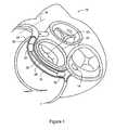
- FIG. 1is a schematic view of a tissue shaping device according to a preferred embodiment as deployed within a coronary sinus.
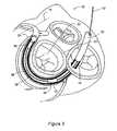
- FIG. 2is a schematic view of a tissue shaping device according to an alternative embodiment as deployed within a coronary sinus.
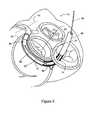
- FIG. 3is a schematic view of a tissue shaping device being delivered to a coronary sinus within a catheter.
- FIG. 4is a schematic view of a partially deployed tissue shaping device within a coronary sinus.
- FIG. 5is a schematic view of a partially deployed and cinched tissue shaping device within a coronary sinus.
- FIG. 6is an elevational view of yet another embodiment of a tissue shaping device according to this invention.
- FIG. 7is a schematic drawing showing a method of determining the crossover point between a circumflex artery and a coronary sinus.
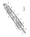
- FIG. 8is a perspective drawing of a tissue shaping device according to one embodiment of this invention.
- FIG. 9is a partial sectional view of the tissue shaping device of FIG. 8 in an unexpanded configuration within a catheter.
- FIG. 10is a perspective view of an anchor for use with a tissue shaping device according to this invention.
- FIG. 11is a perspective view of another anchor for use with a tissue shaping device according to this invention.
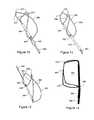
- FIG. 12is a perspective view of yet another anchor for use with a tissue shaping device according to this invention.
- FIG. 13is a perspective view of still another anchor for use with a tissue shaping device according to this invention.
- FIG. 14is a perspective view of another anchor for use with a tissue shaping device according to this invention.
- FIG. 15is a perspective view of yet another anchor for use with a tissue shaping device according to this invention.
- FIG. 16is a perspective view of part of an anchor for use with a tissue shaping device according to this invention.
- FIG. 17is a perspective view of still another anchor for use with a tissue shaping device according to this invention.
- FIG. 18is a perspective view of another anchor for use with a tissue shaping device according to this invention.
- FIG. 19is a perspective view of yet another anchor for use with a tissue shaping device according to this invention.
- FIG. 20is a perspective view of still another anchor for use with a tissue shaping device according to this invention.
- FIG. 21is a perspective view of a tandem anchor for use with a tissue shaping device according to this invention.
- FIG. 22is a perspective view of a connector with integral anchor crimps for us in a tissue shaping device according to this invention.
- FIG. 23is a perspective view of a tissue shaping device employing the connector of FIG. 22 .
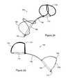
- FIG. 24is a perspective view of another connector for use with a tissue shaping device according to this invention.
- FIG. 25is a perspective view of yet another connector for use with a tissue shaping device according to this invention.
- FIG. 26is a side view of a connector for use with a tissue shaping device according to this invention.
- FIG. 27is a side view of another connector for use with a tissue shaping device according to this invention.
- FIG. 28is a perspective view of yet another tissue shaping device according to this invention.
- FIG. 29is a side view of the tissue shaping device shown in FIG. 28 .
- FIG. 30is a schematic view of another embodiment demonstrating the method of this invention.
- FIG. 31is a schematic view of yet another embodiment demonstrating the method of this invention.
- FIG. 1shows a partial view of a human heart 10 and some surrounding anatomical structures.
- the main coronary venous vesselis the coronary sinus 12 , defined as starting at the ostium 14 or opening to the right atrium and extending through the great cardiac vein to the anterior interventricular (“AIV”) sulcus or groove 16 .
- AIVanterior interventricular
- the mitral valve 20surrounded by the mitral valve annulus 22 and adjacent to at least a portion of the coronary sinus 12 .
- the circumflex artery 24 shown in FIG. 1passes between the coronary sinus 12 and the heart. The relative size and location of each of these structures vary from person to person
- tissue shaping device 30Disposed within the coronary sinus 12 is a tissue shaping device 30 . As shown in FIG. 1 , the distal end 32 of device 30 is disposed proximal to circumflex artery 24 to reshape the adjacent mitral valve annulus 22 and thereby reduce mitral valve regurgitation. As shown in FIG. 1 , device 30 has a distal anchor 34 , a proximal anchor 36 and a connector 38 .
- proximal anchor 36is deployed completely within the coronary sinus. In the alternative embodiment shown in FIG. 2 , proximal anchor is deployed at least partially outside the coronary sinus.
- FIGS. 3-6show a method according to this invention.
- a catheter 50is maneuvered in a manner known in the art through the ostium 14 into coronary sinus 12 .
- catheter 50preferably has an outer diameter no greater than ten french, most preferably with an outer diameter no more than nine french.
- device 30Disposed within catheter 50 is device 30 in an unexpanded configuration, and extending back through catheter 50 from device 30 to the exterior of the patient is a tether or control wire 52 .
- control wire 52may include multiple tether and control wire elements, such as those described in U.S. patent application Ser. No. 10/331,143.
- the deviceis deployed as far distally as possible without applying substantial compressive force on the circumflex or other major coronary artery.
- the distal end of catheter 50is disposed at a distal anchor location proximal of the crossover point between the circumflex artery 24 and the coronary sinus 12 as shown in FIG. 3 .
- catheter 50is withdrawn proximally while device 30 is held stationary by control wire 52 to uncover distal anchor 34 at the distal anchor location within coronary sinus 12 .
- the cathetermay be held stationary while device 30 is advanced distally to uncover the distal anchor.
- distal anchor 34engages the coronary sinus wall to provide an anchoring force of at least one pound, most preferably an anchoring force of at least two pounds.
- the anchor's expansion energy to supply the anchoring forcecomes from strain energy stored in the anchor due to its compression for catheter delivery, from an actuation force, or a combination of both, depending on anchor design.
- catheter 50While device 30 is held in place by the anchoring force of distal anchor 34 , catheter 50 is withdrawn further proximally to a point just distal of proximal anchor 36 , as shown in FIG. 5 .
- a proximally directed forceis then exerted on distal anchor 34 by control wire 52 through connector 38 .
- the distance between the distal and proximal anchors along the connectoris fixed, so the proximally directed force moves proximal anchor 36 proximally with respect to the coronary sinus while distal anchor 34 remains stationary with respect to the coronary sinus.
- the proximal anchoris moved proximally about 1-6 cm., most preferably at least 2 cm., in response to the proximally directed force.
- the proximal anchormay stay substantially stationary with respect to the coronary sinus despite the application of a proximally directed force on the distal anchor.
- the proximal anchoris deployed.
- Other patient vital signssuch as cardiac perfusion, may also be monitored during this procedure as described in U.S. patent application Ser. No. 10/366,585.
- the proximal anchor's anchoring forcei.e., the force with which the proximal anchor resists moving in response to a distally-directed force, must be sufficient not only to maintain the device's position within the coronary sinus but also to enable the device to maintain the adjacent tissue's cinched shape.
- the proximal anchorengages the coronary sinus wall to provide an anchoring force of at least one pound, most preferably an anchoring force of at least two pounds.
- the proximal anchor's expansion energy to supply the anchoring forcecomes from strain energy stored in the anchor due to its compression for catheter delivery, from an actuation force, or a combination of both, depending on anchor design.
- the proximal anchoris deployed by withdrawing catheter 50 proximally to uncover proximal anchor 36 , then either permitting proximal anchor 36 to self-expand, applying an actuation force to expand the anchor, or a combination of both.
- the control wire 52is then detached, and catheter 50 is removed from the patient.
- the device location and configuration as deployed according to this methodis as shown in FIG. 1 .
- proximal anchor 36may be deployed at least partially outside of the coronary sinus after cinching to modify the shape of the mitral valve tissue, as shown in FIG. 2 .
- distal anchor 34is disposed proximal to the crossover point between coronary sinus 12 and circumflex artery 24 , all of the anchoring and tissue reshaping force applied to the coronary sinus by device 30 is solely proximal to the crossover point.
- the proximal anchormay be deployed prior to the application of the proximally directed force to cinch the device to reshape the mitral valve tissue.
- FIG. 6One example of a device according to this embodiment is shown in FIG. 6 .
- Device 60includes a self-expanding distal anchor 62 , a self-expanding proximal anchor 64 and a connector 66 .
- the design of distal anchor 62enables it to maintain its anchoring force when a proximally directed force is applied on it to cinch, while the design of proximal anchor 64 permits it to be moved proximally after deployment while resisting distal movement after cinching. Cinching after proximal anchor deployment is described in more detail in U.S.
- distal anchor 62is disposed proximal to the crossover point between coronary sinus 12 and circumflex artery 24 so that all of anchoring and tissue reshaping force applied to the coronary sinus by device 30 is solely proximal to the crossover point.
- the device or one of its anchorsmay be recaptured.
- catheter 50may be moved distally to place proximal anchor 36 back inside catheter 50 , e.g., to the configuration shown in FIG. 5 . From this position, the cinching force along connector 38 may be increased or decreased, and proximal anchor 36 may then be redeployed.
- catheter 50may be advanced distally to recapture both proximal anchor 36 and distal anchor 34 , e.g., to the configuration shown in FIG. 3 . From this position, distal anchor 34 may be redeployed, a cinching force applied, and proximal anchor 36 deployed as discussed above. Also from this position, device 30 may be removed from the patient entirely by simply withdrawing the catheter from the patient.
- Fluoroscopye.g., angiograms and venograms
- Fluoroscopymay be used to determine the relative positions of the coronary sinus and the coronary arteries such as the circumflex artery, including the crossover point between the vessels and whether or not the artery is between the coronary sinus and the heart.
- Radiopaque dyemay be injected into the coronary sinus and into the arteries in a known manner while the heart is viewed on a fluoroscope.
- FIG. 7An alternative method of determining the relative positions of the vessels is shown in FIG. 7 .
- guide wires 70 and 72are inserted into the coronary sinus 12 and into the circumflex artery 24 or other coronary artery, and the relative positions of the guide wires are viewed on a fluoroscope to identify the crossover point 74 .
- FIG. 8illustrates one embodiment of a tissue shaping device in accordance with the present invention.
- the tissue shaping device 100includes a connector or support wire 102 having a proximal end 104 and a distal end 106 .
- the support wire 102is made of a biocompatible material such as stainless steel or a shape memory material such as nitinol wire.
- connector 102comprises a double length of nitinol wire that has both ends positioned within a distal crimp tube 108 .
- Proximal to the proximal end of the crimp tube 108is a distal lock bump 110 that is formed by the support wire bending away from the longitudinal axis of the support 102 and then being bent parallel to the longitudinal axis of the support before being bent again towards the longitudinal axis of the support to form one half 110 a of distal lock bump 110 .
- the wirecontinues proximally through a proximal crimp tube 112 .
- the wireOn exiting the proximal end of the proximal crimp tube 112 , the wire is bent to form an arrowhead-shaped proximal lock bump 114 .
- the wire of the support 102then returns distally through the proximal crimp tube 112 to a position just proximal to the proximal end of the distal crimp tube 108 wherein the wire is bent to form a second half 10 b of the distal lock 110 .
- the wireis then bent to form a double loop eyelet or loop 122 around the longitudinal axis of the support wire 102 before extending radially outwards and distally back over the longitudinal axis of the crimp tube 108 to form the other leg of the figure eight. Finally, the wire is bent proximally into the distal end of the crimp tube 108 to complete the distal anchor 120 .
- the distal anchoris expanded by using a catheter or locking tool to exert an actuation force sliding eyelet 122 of the distal anchor from a position that is proximal to distal lock bump 110 on the connector to a position that is distal to distal lock bump 110 .
- the bent-out portions 110 a and 110 b of connector 110are spaced wider than the width of eyelet 122 and provide camming surfaces for the locking action. Distal movement of eyelet 122 pushes these camming surfaces inward to permit eyelet 122 to pass distally of the lock bump 110 , then return to their original spacing to keep eyelet 122 in the locked position.
- Actuatable proximal anchor 140is formed and actuated in a similar manner by moving eyelet 142 over lock bump 114 . Both the distal and the proximal anchor provide anchoring forces of at least one pound, and most preferably two pounds.
- FIG. 9illustrates one method for delivering a tissue shaping device 100 in accordance with the present invention to a desired location in the body, such as the coronary sinus to treat mitral valve regurgitation.
- device 100is preferably loaded into and routed to a desired location within a catheter 200 with the proximal and distal anchors in an unexpanded or deformed condition. That is, eyelet 122 of distal anchor 120 is positioned proximal to the distal lock bump 110 and the eyelet 142 of the proximal anchor 140 is positioned proximal to the proximal lock bump 114 .
- the physicianejects the distal end of the device from the catheter 200 into the coronary sinus by advancing the device or retracting the catheter or a combination thereof.
- a pusher(not shown) provides distal movement of the device with respect to catheter 200
- a tether 201provides proximal movement of the device with respect to catheter 200 .
- the distal anchorbegins to expand as soon as it is outside the catheter.
- catheter 200is advanced to place an actuation force on distal anchor eyelet 122 to push it distally over the distal lock bump 110 so that the distal anchor 120 further expands and locks in place to securely engage the wall of the coronary sinus.
- a proximally-directed forceis applied to connector 102 and distal anchor 120 via a tether or control wire 201 extending through catheter outside the patient to apply sufficient pressure on the tissue adjacent the connector to modify the shape of that tissue.
- fluoroscopy, ultrasound or other imaging technologymay be used to see when the device supplies sufficient pressure on the mitral valve to aid in its complete closure with each ventricular contraction without otherwise adversely affecting the patient.
- proximal anchor 140moves proximally.
- proximal anchor 140can be moved about 1-6 cm., most preferably at least 2 cm., proximally to reshape the mitral valve tissue.
- the proximal anchor 140is then deployed from the catheter and allowed to begin its expansion.
- the locking toolapplies an actuation force on proximal anchor eyelet 142 to advance it distally over the proximal lock bump 114 to expand and lock the proximal anchor, thereby securely engaging the coronary sinus wall to maintain the proximal anchor's position and to maintain the reshaping pressure of the connector against the coronary sinus wall.
- catheter 200may be advanced to lock proximal anchor 140 .
- the mechanism for securing the proximal end of the devicecan be released.
- the securementis made with a braided loop 202 at the end of tether 201 and a lock wire 204 .
- the lock wire 204is withdrawn thereby releasing the loop 202 so it can be pulled through the proximal lock bump 114 at the proximal end of device 100 .
- Reduction in mitral valve regurgitation using devices of this inventioncan be maximized by deploying the distal anchor as far distally in the coronary sinus as possible.
- anchor 120 in its unexpanded configurationextends proximally along connector 102 within catheter 200 .
- a preferred catheter diameteris ten french or less (most preferably nine french), and the tissue shaping device in its unexpanded configuration must fit within the catheter.
- FIGS. 10-23show embodiments of the device of this invention having flexible and expandable wire anchors which permit the delivery of tissue shaping devices 60 mm or less in length by a ten french (or less) catheter.
- one or both of the anchorsare provided with bending points about which the anchors deform when placed in their unexpanded configuration for delivery by a catheter or recapture into a catheter. These bending points enable the anchors to deform into configurations that minimize overlap with other elements of the device.
- the distal anchoris self-expanding, thereby avoiding the need for a proximally-extending eyelet in the anchor's unexpanded configuration that might overlap with the unexpanded proximal anchor within the delivery and/or recapture catheter.
- FIG. 10shows an actuatable anchor design suitable for a shorter tissue shaping device similar to the device shown in FIGS. 8 and 9 .
- distal anchor 300is disposed distal to a connector 302 .
- anchor 300is formed in a figure eight configuration from flexible wire such as nitinol held by a crimp tube 304 .
- An eyelet 306is formed around the longitudinal axis of connector 302 . A distally directed actuation force on eyelet 306 moves it over a lock bump 308 formed in connector 302 to actuate and lock anchor 300 .
- FIG. 10shows anchor 300 in an expanded configuration.
- eyelet 306is disposed proximal to lock bump 308 , and the figure eight loops of anchor 300 are compressed against crimp 304 .
- eyelet 306In order to limit the proximal distance eyelet 306 must be moved along the connector to compress anchor 300 into an unexpanded configuration, bending points 310 are formed in the distal struts of anchor 300 . Bending points 310 are essentially kinks, i.e., points of increased curvature, formed in the wire.
- bending points 310deform such that the upper arms 312 of the distal struts bend around bending points 310 and move toward the lower arms 314 of the distal struts, thereby limiting the distance eyelet 306 and the anchor's proximal struts must be moved proximally along the connector to compress the anchor.
- anchor 300would deform about bending points 310 to limit the cross-sectional profile of the anchor within the catheter, even if eyelet 306 were not moved proximally over lock bump 308 during the recapture procedure. Bending points may also be provided on the proximal anchor in a similar fashion.
- anchor 300is its ability to conform and adapt to a variety of vessel sizes. For example, when anchor 300 is expanded inside a vessel such as the coronary sinus, the anchor's wire arms may contact the coronary sinus wall before the eyelet 306 has been advanced distally over lock bump 308 to lock the anchor in place. While continued distal advancement of eyelet 306 will create some outward force on the coronary sinus wall, much of the energy put into the anchor by the anchor actuation force will be absorbed by the deformation of the distal struts about bending points 310 , which serve as expansion energy absorption elements and thereby limit the radially outward force on the coronary sinus wall. This feature enables the anchor to be used in a wider range of vessel sizes while reducing the risk of over-expanding the vessel.
- FIG. 11shows another anchor design suitable for a shorter tissue shaping device similar to the device shown in FIGS. 8 and 9 .
- distal anchor 320is disposed distal to a connector 322 .
- anchor 320is formed in a figure eight configuration from flexible wire such as nitinol held by a crimp tube 324 .
- anchor 320is self-expanding and is not actuatable.
- Eyelet 326is held in place by a second crimp 325 to limit or eliminate movement of the anchor's proximal connection point proximally or distally, e.g., along connector 322 .
- FIG. 11shows anchor 320 in an expanded configuration.
- an unexpanded configurationsuch as a configuration suitable for loading anchor 320 and the rest of the tissue shaping device into a catheter for initial deployment to treat mitral valve regurgitation
- the figure eight loops of anchor 320are compressed.
- Bending points 330are formed in the distal struts of anchor 320 .
- bending points 330deform such that the upper arms 332 of the distal struts bend around bending points 330 and move toward the lower arms 334 of the distal struts.
- very little or none of the wire portion of anchor 320is disposed proximally along crimp 325 or connector 322 when anchor 320 is in its unexpanded configuration.
- anchor 320would deform about bending points 330 to limit the cross-sectional profile of the anchor within the catheter. Bending points may also be provided on the proximal anchor in a similar fashion.
- Distal anchor 320may be part of a tissue shaping device (such as that shown in FIGS. 8 and 9 ) having a proximal anchor and a connector disposed between the anchors. Due to the superelastic properties of its shape memory material, distal anchor 320 may be deployed from a catheter to self-expand to anchor against the coronary sinus wall to provide an anchoring force of at least one pound, preferably at least two pounds. A proximally directed force may then be applied to distal anchor 320 through connector 322 , such as by moving the proximal anchor proximally about 1-6 cm., more preferably at least 2 cm., by pulling on a tether or control wire operated from outside the patient. The proximal anchor may then be deployed to maintain the reshaping force of the device.
- FIG. 12shows another embodiment of an anchor suitable for use in a shorter tissue shaping device.
- distal anchor 340is disposed distal to a connector 342 .
- anchor 340is formed in a figure eight configuration from flexible wire such as nitinol held by a crimp tube 344 .
- anchor 340is self-expanding and is not actuatable.
- the loop of anchor 340 forming the anchor's proximal strutspasses through a loop 346 extending distally from a second crimp 345 to limit or eliminate movement of the anchor's proximal struts proximally or distally, e.g., along connector 342 .
- FIG. 12shows anchor 340 in an expanded configuration.
- an unexpanded configurationsuch as a configuration suitable for loading anchor 340 and the rest of the tissue shaping device into a catheter for initial deployment to treat mitral valve regurgitation
- the figure eight loops of anchor 340are compressed.
- bending points 350are formed in the proximal struts of anchor 340 .
- anchor 340is compressed into an unexpanded configuration
- bending points 350deform such that the upper arms 352 of the distal struts bend around bending points 350 and move toward the lower arms 354 of the distal struts.
- the amount of the wire portion of anchor 340 extending proximally along crimp 345 and connector 342 in its unexpanded configurationdepends on the location of bending points 350 .
- the bending pointsare formed at the tallest and widest part of the proximal struts.
- Distal anchor 340may be part of a tissue shaping device (such as that shown in FIGS. 8 and 9 ) having a proximal anchor and a connector disposed between the anchors. Due to the superelastic properties of its shape memory material, distal anchor 340 may be deployed from a catheter to self-expand to anchor against the coronary sinus wall to provide an anchoring force of at least one pound, preferably at least two pounds. A proximally directed force may then be applied to distal anchor 340 through connector 342 , such as by moving the proximal anchor proximally about 1-6 cm., more preferably at least 2 cm., by pulling on a tether or control wire operated from outside the patient. The proximal anchor may then be deployed to maintain the reshaping force of the device.
- Bending points 350also add to the anchoring force of distal anchor 340 , e.g., by causing the anchor height to increase as the proximal struts become more perpendicular to the connector in response to a proximally directed force, thereby increasing the anchoring force.
- bending pointsmay be added to the distal struts of a proximal anchor to increase the proximal anchor's anchoring force in response to a distally directed force.
- FIG. 13shows yet another embodiment of an anchor suitable for use in a shorter tissue shaping device.
- distal anchor 360is disposed distal to a connector 362 .
- anchor 360is formed in a figure eight configuration from flexible wire such as nitinol held by a crimp tube 364 .
- anchor 360is self-expanding and is not actuatable.
- the loop of anchor 360 forming the anchor's proximal strutspasses through a loop 366 extending distally from a second crimp 365 to limit or eliminate movement of the anchor's proximal struts proximally or distally, e.g., along connector 362 .
- FIG. 13shows anchor 360 in an expanded configuration.
- an unexpanded configurationsuch as a configuration suitable for loading anchor 360 and the rest of the tissue shaping device into a catheter for initial deployment to treat mitral valve regurgitation
- the figure eight loops of anchor 360are compressed.
- bending points 370are formed in both the proximal struts and the distal struts of anchor 360 .
- Anchor 360may be used as part of a tissue shaping device like the embodiments discussed above.
- FIG. 14shows an actuatable anchor design suitable for a shorter tissue shaping device similar to the device shown in FIGS. 8 and 9 .
- distal anchor 380is disposed distal to a connector 382 .
- anchor 380is formed in a figure eight configuration from flexible wire such as nitinol held by a crimp tube 384 .
- eyelets 386 and 387are formed in each of the anchor's proximal struts around the longitudinal axis of connector 382 . This arrangement reduces the radially outward force of the anchor.
- a distally directed actuation force on eyelets 386 and 387move them over a lock bump 388 formed in connector 382 to actuate and lock anchor 380 .
- FIG. 14shows anchor 380 in an expanded configuration.
- an unexpanded configurationsuch as a configuration suitable for loading anchor 380 and the rest of the tissue shaping device into a catheter for initial deployment to treat mitral valve regurgitation
- eyelets 386 and 387are disposed proximal to lock bump 388 and the figure eight loops of anchor 380 are compressed against crimp 384 .
- bending points 390are formed in the distal struts of anchor 380 .
- bending points 390deform such that the upper arms 392 of the distal struts bend around bending points 390 and move toward the lower arms 394 of the distal struts, thereby limiting the distance eyelets 386 and 387 and the anchor's proximal struts must be moved proximally along the connector to compress the anchor.
- anchor 380would deform about bending points 390 to limit the cross-sectional profile of the anchor within the catheter, even if eyelets 386 and 387 were not moved proximally over lock bump 388 during the recapture procedure. Bending points may also be provided on the proximal anchor in a similar fashion.
- distal anchor 380may be part of a tissue shaping device (such as that shown in FIGS. 8 and 9 ) having a proximal anchor and a connector disposed between the anchors.
- tissue shaping devicesuch as that shown in FIGS. 8 and 9
- distal anchor 380may be deployed from a catheter and expanded with an actuation force to anchor against the coronary sinus wall to provide an anchoring force of at least one pound, preferably at least two pounds, and to lock anchor 380 in an expanded configuration.
- a proximally directed forceis applied to distal anchor 380 through connector 382 , such as by moving the proximal anchor proximally about 1-6 cm., more preferably at least 2 cm., by pulling on a tether or control wire operated from outside the patient.
- the proximal anchormay then be deployed to maintain the reshaping force of the device.
- one aspect of anchor 380is its ability to conform and adapt to a variety of vessel sizes.
- the anchor's wire armsmay contact the coronary sinus wall before the eyelets 386 and 387 have been advance distally over lock bump 388 to lock the anchor in place. While continued distal advancement of eyelet 386 will create some outward force on the coronary sinus wall, much of the energy put into the anchor by the anchor actuation force will be absorbed by the deformation of the distal struts about bending points 390 .
- FIG. 15shows yet another embodiment of an actuatable anchor for use in a shorter tissue shaping device.
- Proximal anchor 400is disposed proximal to a connector 402 .
- anchor 400is formed in a figure eight configuration from flexible wire such as nitinol held by a crimp tube 404 .
- An eyelet 406is formed around a lock bump 408 extending proximally from crimp 404 . A distally directed actuation force on eyelet 406 moves it over lock bump 408 to actuate and lock anchor 400 .
- FIG. 15shows anchor 400 in an expanded configuration.
- bending points 410formed as loops in the anchor wire deform such that the upper arms 412 of the distal struts bend around bending points 410 and move toward the lower arms 414 of the distal struts.
- proximal anchor 400may be part of a tissue shaping device (such as that shown in FIGS. 8 and 9 ) having a distal anchor and a connector disposed between the anchors.
- one aspect of anchor 400is its ability to conform and adapt to a variety of vessel sizes.
- the anchor's wire armsmay contact the coronary sinus wall before the eyelet 406 has been advanced distally over lock bump 408 to lock the anchor in place. While continued distal advancement of eyelet 406 will create some outward force on the coronary sinus wall, much of the energy put into the anchor by the anchor actuation force will be absorbed by the deformation of the distal struts about bending points 410 , which serve as expansion energy absorption elements and thereby limit the radially outward force on the coronary sinus wall.
- the looped bending points of the FIG. 15 embodimentmay be formed on the anchor's proximal struts in addition to or instead of on the distal struts.
- the looped bending point embodimentmay also be used in a distal anchor, as shown in FIG. 16 (without the crimp or connector). Note that in the embodiment of FIG. 16 the proximal and distal struts of anchor 420 as well as the eyelet 422 and bending points 424 are formed from a single wire.
- FIG. 17shows an embodiment of a distal anchor 440 similar to that of FIG. 10 suitable for use in a shorter tissue shaping device.
- extra twists 442are added at the apex of the anchor's figure eight pattern.
- bending points 444are formed in the anchor's distal struts.
- anchor 440is actuatable by moving eyelet 446 distally over a lock bump 448 formed in connector 450 .
- Anchor 440may also be made as a self-expanding anchor by limiting or eliminating movement of the proximal struts of anchor 440 along connector 450 , as in the embodiment shown in FIG. 11 .
- the bending pointshelp anchor 440 adapt and conform to different vessel sizes.
- the extra twists 442also help the anchor adapt to different vessel diameters by keeping the anchor's apex together.
- anchor 440is preferably formed from nitinol wire.
- Anchor 440may be used as part of a tissue shaping device in a manner similar to the anchor of FIG. 10 (for the actuatable anchor embodiment) or the anchor of FIG. 11 (for the self-expanding anchor embodiment).
- Anchor 440may also be used as a proximal anchor.
- FIG. 18shows an embodiment of a distal anchor 460 similar to that of FIG. 17 .
- the bending points 462are formed in the anchor's proximal struts, as in the self-expanding anchor shown in FIG. 12 .
- extra twists 464are added at the apex of the anchor's figure eight pattern.
- anchor 460is actuatable by moving eyelet 466 distally over a lock bump 468 formed in connector 470 .
- Anchor 460may also be made as a self-expanding anchor by limiting or eliminating movement of the proximal connection point of anchor 460 along connector 470 , as in the embodiment shown in FIG. 11 .
- the bending pointshelp anchor 460 adapt and conform to different vessel sizes.
- the extra twists 464also help the anchor adapt to different vessel diameters by keeping the anchor's apex together.
- anchor 460is preferably formed from nitinol wire.
- Anchor 460may be used as part of a tissue shaping device in a manner similar to the anchor of FIG. 10 (for the actuatable anchor embodiment) or the anchor of FIG. 11 (for the self-expanding anchor embodiment).
- Anchor 460may also be used as a proximal anchor.
- FIG. 19shows an embodiment of a self-expanding distal anchor 480 suitable for use in a shorter tissue shaping device.
- anchor 480is formed in a figure eight configuration from flexible wire such as nitinol held by a crimp tube 482 .
- the base of the figure eight patternis narrower in this embodiment, however, with the anchor's proximal struts 484 passing through crimp 482 .
- Distal anchor 480may be part of a tissue shaping device (such as that shown in FIGS. 8 and 9 ) having a proximal anchor and a connector disposed between the anchors.
- tissue shaping devicesuch as that shown in FIGS. 8 and 9
- distal anchor 480may be deployed from a catheter and allowed to self-expand to anchor against the coronary sinus wall to provide an anchoring force of at least one pound, preferably at least two pounds.
- a proximally directed forceis applied to distal anchor 480 through connector 486 , such as by moving the proximal anchor proximally about 1-6 cm., more preferably at least 2 cm., by pulling on a tether or control wire operated from outside the patient.
- the proximal anchormay then be deployed to maintain the reshaping force of the device.
- FIG. 20shows an embodiment of a distal anchor suitable for use in a shorter tissue shaping device and similar to that of FIG. 10 .
- distal anchor 500is disposed distal to a connector 502 .
- anchor 500is formed in a figure eight configuration from flexible wire such as nitinol held by a crimp tube 504 .
- An eyelet 506is formed around the longitudinal axis of connector 502 .
- a distally directed actuation force on eyelet 506moves it over a lock bump 508 formed in connector 502 to actuate and lock anchor 500 .
- proximal struts 501 and the angle of distal struts 503are wider than corresponding angles in the FIG. 10 embodiment, however, causing anchor 500 to distend more in width than in height when expanded, as shown.
- eyelet 506is disposed proximal to lock bump 508 and the figure eight loops of anchor 500 are compressed against crimp 504 .
- bending points 510are formed in the distal struts 503 , as in the FIG. 10 embodiment, to limit the width of the device in its unexpanded configuration within a catheter.
- Distal anchor 500may be part of a tissue shaping device (such as that shown in FIGS. 8 and 9 ) having a proximal anchor and a connector disposed between the anchors.
- tissue shaping devicesuch as that shown in FIGS. 8 and 9
- distal anchor 500may be deployed from a catheter and expanded with an actuation force to anchor against the coronary sinus wall to provide an anchoring force of at least one pound, preferably at least two pounds, and to lock anchor 500 in an expanded configuration.
- a proximally directed forceis applied to distal anchor 500 through connector 502 , such as by moving the proximal anchor proximally about 1-6 cm., more preferably at least 2 cm., by pulling on a tether or control wire operated from outside the patient.
- the proximal anchormay then be deployed to maintain the reshaping force of the device.
- the anchor shown in FIG. 20may be used as a proximal anchor. This anchor may also be formed as a self-expanding anchor.
- FIG. 21shows a tandem distal anchor according to another embodiment of this invention.
- Self-expanding anchor 520is formed in a figure eight configuration from flexible wire such as nitinol held by a crimp tube 522 .
- Eyelet 524is held in place by the distal end of actuatable anchor 540 to limit or eliminate proximal and distal movement of the proximal struts of anchor 520 .
- bending points 530are formed in the distal struts of anchor 520 . Depending upon the exact location of bending points 530 , very little or none of the wire portion of anchor 520 is disposed proximal to the distal end of anchor 540 when anchor 520 is in its unexpanded configuration.
- anchor 520would deform about bending points 530 to limit the cross-sectional profile of the anchor within the catheter. Bending points may also be provided on the proximal anchor in a similar fashion.
- Anchor 540is similar to anchor 120 shown in FIG. 8 .
- Anchor 540is formed in a figure eight configuration from flexible wire such as nitinol held by a crimp tube 544 .
- An eyelet 546is formed around the longitudinal axis of connector 542 .
- a distally directed actuation force on eyelet 546moves it over a lock bump 548 formed in connector 542 to actuate and lock anchor 540 .
- Tandem anchors 520 and 540may be part of a tissue shaping device (such as that shown in FIGS. 8 and 9 ) having a proximal anchor and a connector disposed between the anchors.
- Anchors 520 and 540may be made from a single wire or from separate pieces of wire.
- distal anchors 520 and 540may be deployed from a catheter.
- Self-expanding anchor 520will then self-expand, and actuatable anchor 540 may be expanded and locked with an actuation force, to anchor both anchors against the coronary sinus wall to provide an anchoring force of at least one pound, preferably at least two pounds.
- a proximally directed forceis applied to anchors 520 and 540 through connector 542 , such as by moving the proximal anchor proximally about 1-6 cm., more preferably at least 2 cm., by pulling on a tether or control wire operated from outside the patient.
- the proximal anchormay then be deployed to maintain the reshaping force of the device.
- FIGS. 22 and 23show an alternative embodiment in which the device's connector 560 is made integral with the distal and proximal crimp tubes 562 and 564 .
- connector 560is formed by cutting away a section of a blank such as a nitinol (or other suitable material such as stainless steel) cylinder or tube, leaving crimp tube portions 562 and 564 intact.
- the radius of the semi-circular cross-section connectoris therefore the same as the radii of the two anchor crimp tubes.
- the devicemay be formed from a blank shaped as a flat ribbon or sheet by removing rectangular edge sections from a central section, creating an I-shaped sheet (e.g., nitinol or stainless steel) having greater widths at the ends and a narrower width in the center connector portion. The ends can then be rolled to form the crimp tubes, leaving the connector substantially flat.
- the connectorcan be made integral with just one of the anchors.
- a distal anchor 566is formed in a figure eight configuration from flexible wire such as nitinol.
- Distal anchor 566is self-expanding, and its proximal struts 568 are held in place by crimp tube 562 .
- Optional bending pointsmay be formed in the proximal struts 568 or distal struts 570 of anchor 566 .
- a proximal anchor 572is also formed in a figure eight configuration from flexible wire such as nitinol with an eyelet 574 on its proximal end.
- a distally directed actuation force on eyelet 574moves it over a lock bump 576 extending proximally from crimp tube 564 to actuate and lock anchor 572 .
- Lock bump 576also serves as the connection point for a tether or control wire to deploy and actuate device in the manner described above with respect to FIGS. 8 and 9 .
- Optional bending pointsmay be formed in the proximal or distal struts of anchor 572 .
- FIG. 24shows an alternative connector for use with the tissue shaping devices of this invention that distributes over more of the device any strain caused by the beat to beat bending and tensile loading.
- Connector 600has a proximal anchor area 602 , a distal anchor area 604 and a central area 606 .
- the distal anchor areamay be longer than the distal anchor attached to it, and the proximal anchor area may be longer than the proximal anchor attached to it.
- An optional lock bump 608may be formed at the proximal end of connector 600 for use with an actuatable proximal anchor and for connecting to a tether or control wire, as described above.
- An optional bulb 610may be formed at the distal end of connector 600 to prevent accidental distal slippage of a distal anchor.
- connector 600In order to reduce material fatigue caused by the heartbeat to heartbeat loading and unloading of the tissue shaping device, the moment of inertia of connector 600 varies along its length, particularly in the portion of connector disposed between the two anchors.
- connector 600is formed as a ribbon or sheet and is preferably formed from nitinol having a rectangular cross-sectional area.
- the thickness of connector 600is preferably constant in the proximal anchor area 602 and the distal anchor area 604 to facilitate attachment of crimps and other components of the anchors.
- the central area 606has a decreasing thickness (and therefore a decreasing moment of inertia) from the border between central area 606 and proximal anchor area 602 to a point about at the center of central area 606 , and an increasing thickness (and increasing moment of inertia) from that point to the border between central area 606 and distal anchor area 604 .
- the varying thickness and varying cross-sectional shape of connector 600change its moment of inertia along its length, thereby helping distribute over a wider area any strain from the heartbeat to heartbeat loading and unloading of the device and reducing the chance of fatigue failure of the connector material.
- FIG. 25shows another embodiment of the connector.
- connector 620has a proximal anchor area 622 , a distal anchor area 624 and a central area 626 .
- Proximal anchor area 622has an optional two-tined prong 628 formed at its proximal end to facilitate attachment of a crimp and other anchor elements.
- Bent prong portions 629may be formed at the proximal end of the prong to prevent accidental slippage of a proximal anchor.
- An optional bulb 630may be formed at the distal end of connector 620 to prevent accidental distal slippage of a distal anchor.
- connector 620is formed as a ribbon or sheet and is preferably formed from nitinol having a rectangular cross-sectional area.
- the thickness of connector 620is preferably constant in the proximal anchor area 622 and the distal anchor area 624 to facilitate attachment of crimps and other components of the anchors.
- the central area 626has a decreasing thickness (decreasing moment of inertia) from the border between central area 626 and proximal anchor area 622 to a point about at the center of central area 626 , and an increasing thickness (increasing moment of inertia) from that point to the border between central area 626 and distal anchor area 624 .
- the varying thickness and varying cross-sectional shape of connector 620change its moment of inertia along its length, thereby helping distribute over a wider area any strain from the heartbeat to heartbeat loading and unloading of the device and reducing the chance of fatigue failure of the connector material.
- FIG. 26shows a connector 640 in profile.
- Connector 640may be formed like the connectors 600 and 620 or FIGS. 24 and 25 , respectively, or may have some other configuration.
- Connector 640has a proximal anchor area 642 , a distal anchor area 644 and a central area 646 .
- Connector 640is preferably formed as a ribbon or sheet and is preferably formed from nitinol having a rectangular cross-sectional area.
- the thicknesses of proximal anchor area 642 and distal anchor area 644are constant.
- the thickness of central area 646decreases from the border between central area 646 and proximal anchor area 642 to a point distal of that border and increases from a point proximal to the border between distal anchor area 644 and central area 646 to that border.
- the points in the central area where the thickness decrease ends and the thickness increase beginsmay be coincident or may be separated to form an area of uniform thickness within central area 646 .
- the thickness of the central areachanges as a function of the square root of the distance from the borders between the central area and the proximal and distal anchor areas.
- FIG. 27shows yet another embodiment of the connector.
- connector 650may be formed like the connectors 600 and 620 or FIGS. 24 and 25 , respectively, or may have some other configuration.
- Connector 650has a proximal anchor area 652 , a distal anchor area 654 and a central area 656 .
- Connector 650is preferably formed as a ribbon or sheet and is preferably formed from nitinol having a rectangular cross-sectional area.
- proximal anchor area 652 and distal anchor area 654are constant.
- the thickness of a proximal portion 658 of central area 656decreases linearly from the border between central area 656 and proximal anchor area 652 to a constant thickness center portion 662 of central area 656
- the thickness of a distal portion 660 of central area 656increases linearly from center portion 662 to the border between distal anchor area 654 and central area 656 .
- the thickness of the connectormay vary in other ways.
- the cross-sectional shape of the connectormay be other than rectangular and may change over the length of the connector.
- FIGS. 28 and 29show yet another embodiment of the invention.
- Tissue shaping device 700has a connector 706 disposed between a proximal anchor 702 and a distal anchor 704 .
- Connector 706may be formed as a ribbon or sheet, such as the tapered connectors shown in FIGS. 24-27 .
- Actuatable proximal anchor 702is formed in a figure eight configuration from flexible wire such as nitinol and is fastened to connector 706 with a crimp tube 708 .
- self-expanding distal anchor 704is formed in a figure eight configuration from flexible wire such as nitinol and is fastened to connector 706 with a crimp tube 710 .
- a proximal lock bump 716extends proximally from proximal anchor 702 for use in actuating and locking proximal anchor 702 and for connecting to a tether or control wire, as described above.
- Bending points 712are formed in the loops of proximal anchor 702
- bending points 714are formed in the loops of distal anchor 704 .
- the wire portions of anchors 702 and 704bend about bending points 712 and 714 , respectively, to limit the cross-sectional profile of the anchors within the catheter.
- the bending pointsalso affect the anchor strength of the anchors and the adaptability of the anchors to different vessel diameters, as discussed above.
- the diameter of the coronary sinus at the distal and proximal anchor pointscan vary from patient to patient.
- the anchors described abovemay be made in a variety of heights and combined with connectors of varying lengths to accommodate this patient to patient variation.
- tissue shaping devices deployed in the coronary sinus to treat mitral valve regurgitationcan have distal anchor heights ranging from about 7 mm. to about 16 mm. and proximal anchor heights ranging from about 9 mm. to about 20 mm.
- tissue shaping deviceWhen treating a patient for mitral valve regurgitation, estimates can be made of the appropriate length for a tissue shaping device as well as appropriate anchor heights for the distal and proximal anchors. The clinician can then select a tissue shaping device having the appropriate length and anchor sizes from a set or sets of devices with different lengths and different anchor sizes, made, e.g., according to the embodiments described above. These device sets may be aggregated into sets or kits or may simply be a collection or inventory of different tissue shaping devices.
- One way of estimating the appropriate length and anchor sizes of a tissue shaping device for mitral valve regurgitationis to view a fluoroscopic image of a coronary sinus into which a catheter with fluoroscopically viewable markings has been inserted.
- the crossover point between the coronary sinus and the circumflex arterycan be determined as described above, and the screen size of the coronary sinus length proximal to that point and the coronary sinus diameter at the intended anchor locations can be measured.
- the length and diameter measurescan be scaled to actual size.
- a tissue shaping device with the appropriate length and anchor sizescan be selected from a set or inventory of devices for deployment in the patient to treat mitral valve regurgitation.
- FIG. 30shows yet another embodiment of the method of this invention.
- a tissue shaping device 800formed from a substantially straight rigid member 802 is disposed in the coronary sinus 804 to treat mitral valve regurgitation.
- the central portion of rigid member 802exerts a remodeling force anteriorly through the coronary sinus wall toward the mitral valve 806 , while the proximal and distal ends 808 and 810 , respectively, of rigid member 802 exert posteriorly-directed forces on the coronary sinus wall.
- device 800is disposed in relation to the circumflex artery 812 so that all of the anteriorly-directed forces from rigid member 802 are posterior to the crossover point between artery 812 and coronary sinus 804 , despite the fact that distal end 810 of device 800 and a guidewire portion 814 are distal to the crossover point.
- the device of FIG. 30may also include a less rigid portion at the distal end 810 of member 802 to further eliminate any force directed toward the mitral valve distal to the crossover point. Further details of the device (apart from the method of this invention) may be found in U.S. patent application Ser. No. 10/112,354, published as U.S. Patent Appl. Publ. No. 2002/0183838, the disclosure of which is incorporated herein by reference.
- FIG. 31shows another embodiment of the method of this invention.
- Device 900has a substantially straight rigid portion 902 disposed between a proximal angled portion 904 and a distal angled portion 906 within coronary sinus 908 .
- proximal angled portion 904extends through the coronary sinus ostium 910 within a catheter (not shown).
- Distal angled portion 906extends distally to a hooked portion 912 that is preferably disposed in the AIV.
- the device's straight portion 902reshapes the coronary sinus and adjacent tissue to apply an anteriorly directed force through the coronary sinus wall toward the mitral valve 914 . Due to the device's design, this reshaping force is applied solely proximal to the crossover point between coronary sinus 908 and the patient's circumflex artery 916 , despite the fact at least a part of the device's distal portion 906 and hooked portion 912 are disposed distal to the crossover point.
Landscapes
- Health & Medical Sciences (AREA)
- Cardiology (AREA)
- Oral & Maxillofacial Surgery (AREA)
- Transplantation (AREA)
- Engineering & Computer Science (AREA)
- Biomedical Technology (AREA)
- Heart & Thoracic Surgery (AREA)
- Vascular Medicine (AREA)
- Life Sciences & Earth Sciences (AREA)
- Animal Behavior & Ethology (AREA)
- General Health & Medical Sciences (AREA)
- Public Health (AREA)
- Veterinary Medicine (AREA)
- Prostheses (AREA)
- Surgical Instruments (AREA)
Abstract
Description
Claims (6)
Priority Applications (1)
| Application Number | Priority Date | Filing Date | Title |
|---|---|---|---|
| US11/383,115US7814635B2 (en) | 2003-12-19 | 2006-05-12 | Method of making a tissue shaping device |
Applications Claiming Priority (2)
| Application Number | Priority Date | Filing Date | Title |
|---|---|---|---|
| US10/742,742US7794496B2 (en) | 2003-12-19 | 2003-12-19 | Tissue shaping device with integral connector and crimp |
| US11/383,115US7814635B2 (en) | 2003-12-19 | 2006-05-12 | Method of making a tissue shaping device |
Related Parent Applications (1)
| Application Number | Title | Priority Date | Filing Date |
|---|---|---|---|
| US10/742,742DivisionUS7794496B2 (en) | 2003-12-19 | 2003-12-19 | Tissue shaping device with integral connector and crimp |
Publications (2)
| Publication Number | Publication Date |
|---|---|
| US20060191121A1 US20060191121A1 (en) | 2006-08-31 |
| US7814635B2true US7814635B2 (en) | 2010-10-19 |
Family
ID=34678525
Family Applications (2)
| Application Number | Title | Priority Date | Filing Date |
|---|---|---|---|
| US10/742,742Expired - LifetimeUS7794496B2 (en) | 2003-12-19 | 2003-12-19 | Tissue shaping device with integral connector and crimp |
| US11/383,115Active2027-01-03US7814635B2 (en) | 2003-12-19 | 2006-05-12 | Method of making a tissue shaping device |
Family Applications Before (1)
| Application Number | Title | Priority Date | Filing Date |
|---|---|---|---|
| US10/742,742Expired - LifetimeUS7794496B2 (en) | 2003-12-19 | 2003-12-19 | Tissue shaping device with integral connector and crimp |
Country Status (1)
| Country | Link |
|---|---|
| US (2) | US7794496B2 (en) |
Cited By (14)
| Publication number | Priority date | Publication date | Assignee | Title |
|---|---|---|---|---|
| US8250960B2 (en) | 2008-08-11 | 2012-08-28 | Cardiac Dimensions, Inc. | Catheter cutting tool |
| US8974525B2 (en) | 2002-01-30 | 2015-03-10 | Cardiac Dimensions Pty. Ltd. | Tissue shaping device |
| US9339348B2 (en) | 2011-08-20 | 2016-05-17 | Imperial Colege of Science, Technology and Medicine | Devices, systems, and methods for assessing a vessel |
| US9775524B2 (en) | 2011-01-06 | 2017-10-03 | Medsolve Limited | Apparatus and method of assessing a narrowing in a fluid filled tube |
| US9956077B2 (en) | 2003-12-19 | 2018-05-01 | Cardiac Dimensions Pty. Ltd. | Mitral valve annuloplasty device with twisted anchor |
| US10390768B2 (en) | 2011-08-20 | 2019-08-27 | Volcano Corporation | Devices, systems, and methods for visually depicting a vessel and evaluating treatment options |
| US10390953B2 (en) | 2017-03-08 | 2019-08-27 | Cardiac Dimensions Pty. Ltd. | Methods and devices for reducing paravalvular leakage |
| US10456257B2 (en) | 2002-05-08 | 2019-10-29 | Cardiac Dimensions Pty. Ltd. | Tissue shaping device |
| US11026791B2 (en) | 2018-03-20 | 2021-06-08 | Medtronic Vascular, Inc. | Flexible canopy valve repair systems and methods of use |
| US11033257B2 (en) | 2005-01-20 | 2021-06-15 | Cardiac Dimensions Pty. Ltd. | Tissue shaping device |
| US11285005B2 (en) | 2006-07-17 | 2022-03-29 | Cardiac Dimensions Pty. Ltd. | Mitral valve annuloplasty device with twisted anchor |
| US11285003B2 (en) | 2018-03-20 | 2022-03-29 | Medtronic Vascular, Inc. | Prolapse prevention device and methods of use thereof |
| US11311380B2 (en) | 2003-05-02 | 2022-04-26 | Cardiac Dimensions Pty. Ltd. | Device and method for modifying the shape of a body organ |
| US11596771B2 (en) | 2020-12-14 | 2023-03-07 | Cardiac Dimensions Pty. Ltd. | Modular pre-loaded medical implants and delivery systems |
Families Citing this family (62)
| Publication number | Priority date | Publication date | Assignee | Title |
|---|---|---|---|---|
| US6332893B1 (en) | 1997-12-17 | 2001-12-25 | Myocor, Inc. | Valve to myocardium tension members device and method |
| US6440164B1 (en) | 1999-10-21 | 2002-08-27 | Scimed Life Systems, Inc. | Implantable prosthetic valve |
| US6723038B1 (en) | 2000-10-06 | 2004-04-20 | Myocor, Inc. | Methods and devices for improving mitral valve function |
| US6602286B1 (en) | 2000-10-26 | 2003-08-05 | Ernst Peter Strecker | Implantable valve system |
| US6800090B2 (en)* | 2001-05-14 | 2004-10-05 | Cardiac Dimensions, Inc. | Mitral valve therapy device, system and method |
| US7311729B2 (en)* | 2002-01-30 | 2007-12-25 | Cardiac Dimensions, Inc. | Device and method for modifying the shape of a body organ |
| US7635387B2 (en)* | 2001-11-01 | 2009-12-22 | Cardiac Dimensions, Inc. | Adjustable height focal tissue deflector |
| US6949122B2 (en) | 2001-11-01 | 2005-09-27 | Cardiac Dimensions, Inc. | Focused compression mitral valve device and method |
| US6793673B2 (en) | 2002-12-26 | 2004-09-21 | Cardiac Dimensions, Inc. | System and method to effect mitral valve annulus of a heart |
| US7179282B2 (en)* | 2001-12-05 | 2007-02-20 | Cardiac Dimensions, Inc. | Device and method for modifying the shape of a body organ |
| US6908478B2 (en)* | 2001-12-05 | 2005-06-21 | Cardiac Dimensions, Inc. | Anchor and pull mitral valve device and method |
| US6764510B2 (en) | 2002-01-09 | 2004-07-20 | Myocor, Inc. | Devices and methods for heart valve treatment |
| US20050209690A1 (en)* | 2002-01-30 | 2005-09-22 | Mathis Mark L | Body lumen shaping device with cardiac leads |
| US6797001B2 (en)* | 2002-03-11 | 2004-09-28 | Cardiac Dimensions, Inc. | Device, assembly and method for mitral valve repair |
| US6752828B2 (en) | 2002-04-03 | 2004-06-22 | Scimed Life Systems, Inc. | Artificial valve |
| CA2877641C (en) | 2002-05-08 | 2017-01-17 | Cardiac Dimensions Pty. Ltd. | Device and method for modifying the shape of a body organ |
| AU2003285943B2 (en) | 2002-10-24 | 2008-08-21 | Boston Scientific Limited | Venous valve apparatus and method |
| US7112219B2 (en) | 2002-11-12 | 2006-09-26 | Myocor, Inc. | Devices and methods for heart valve treatment |
| US7837729B2 (en) | 2002-12-05 | 2010-11-23 | Cardiac Dimensions, Inc. | Percutaneous mitral valve annuloplasty delivery system |
| US7316708B2 (en) | 2002-12-05 | 2008-01-08 | Cardiac Dimensions, Inc. | Medical device delivery system |
| US6945957B2 (en) | 2002-12-30 | 2005-09-20 | Scimed Life Systems, Inc. | Valve treatment catheter and methods |
| US7314485B2 (en)* | 2003-02-03 | 2008-01-01 | Cardiac Dimensions, Inc. | Mitral valve device using conditioned shape memory alloy |
| US20040158321A1 (en)* | 2003-02-12 | 2004-08-12 | Cardiac Dimensions, Inc. | Method of implanting a mitral valve therapy device |
| US20060161169A1 (en)* | 2003-05-02 | 2006-07-20 | Cardiac Dimensions, Inc., A Delaware Corporation | Device and method for modifying the shape of a body organ |
| US20040220657A1 (en)* | 2003-05-02 | 2004-11-04 | Cardiac Dimensions, Inc., A Washington Corporation | Tissue shaping device with conformable anchors |
| US7887582B2 (en) | 2003-06-05 | 2011-02-15 | Cardiac Dimensions, Inc. | Device and method for modifying the shape of a body organ |
| US7351259B2 (en) | 2003-06-05 | 2008-04-01 | Cardiac Dimensions, Inc. | Device, system and method to affect the mitral valve annulus of a heart |
| US8128681B2 (en) | 2003-12-19 | 2012-03-06 | Boston Scientific Scimed, Inc. | Venous valve apparatus, system, and method |
| US7854761B2 (en) | 2003-12-19 | 2010-12-21 | Boston Scientific Scimed, Inc. | Methods for venous valve replacement with a catheter |
| US7837728B2 (en)* | 2003-12-19 | 2010-11-23 | Cardiac Dimensions, Inc. | Reduced length tissue shaping device |
| US20050137450A1 (en)* | 2003-12-19 | 2005-06-23 | Cardiac Dimensions, Inc., A Washington Corporation | Tapered connector for tissue shaping device |
| US20050137449A1 (en)* | 2003-12-19 | 2005-06-23 | Cardiac Dimensions, Inc. | Tissue shaping device with self-expanding anchors |
| US7794496B2 (en)* | 2003-12-19 | 2010-09-14 | Cardiac Dimensions, Inc. | Tissue shaping device with integral connector and crimp |
| US7566343B2 (en) | 2004-09-02 | 2009-07-28 | Boston Scientific Scimed, Inc. | Cardiac valve, system, and method |
| US20060173490A1 (en) | 2005-02-01 | 2006-08-03 | Boston Scientific Scimed, Inc. | Filter system and method |
| US7854755B2 (en) | 2005-02-01 | 2010-12-21 | Boston Scientific Scimed, Inc. | Vascular catheter, system, and method |
| US7878966B2 (en) | 2005-02-04 | 2011-02-01 | Boston Scientific Scimed, Inc. | Ventricular assist and support device |
| US7780722B2 (en) | 2005-02-07 | 2010-08-24 | Boston Scientific Scimed, Inc. | Venous valve apparatus, system, and method |
| US7670368B2 (en) | 2005-02-07 | 2010-03-02 | Boston Scientific Scimed, Inc. | Venous valve apparatus, system, and method |
| US7867274B2 (en) | 2005-02-23 | 2011-01-11 | Boston Scientific Scimed, Inc. | Valve apparatus, system and method |
| US7722666B2 (en) | 2005-04-15 | 2010-05-25 | Boston Scientific Scimed, Inc. | Valve apparatus, system and method |
| US8012198B2 (en) | 2005-06-10 | 2011-09-06 | Boston Scientific Scimed, Inc. | Venous valve, system, and method |
| US7569071B2 (en) | 2005-09-21 | 2009-08-04 | Boston Scientific Scimed, Inc. | Venous valve, system, and method with sinus pocket |
| US7799038B2 (en) | 2006-01-20 | 2010-09-21 | Boston Scientific Scimed, Inc. | Translumenal apparatus, system, and method |
| US7503932B2 (en)* | 2006-04-11 | 2009-03-17 | Cardiac Dimensions, Inc. | Mitral valve annuloplasty device with vena cava anchor |
| US20080065205A1 (en)* | 2006-09-11 | 2008-03-13 | Duy Nguyen | Retrievable implant and method for treatment of mitral regurgitation |
| US7854849B2 (en)* | 2006-10-10 | 2010-12-21 | Multiphase Systems Integration | Compact multiphase inline bulk water separation method and system for hydrocarbon production |
| US9943409B2 (en) | 2006-11-14 | 2018-04-17 | The United States Of America, As Represented By The Secretary, Department Of Health And Human Services | Transcatheter coronary sinus mitral valve annuloplasty procedure and coronary artery and myocardial protection device |
| US8211171B2 (en) | 2006-11-14 | 2012-07-03 | The United States Of America, As Represented By The Secretary Of The Department Of Health And Human Services | Transcatheter coronary sinus mitral valve annuloplasty procedure and coronary artery and myocardial protection device |
| WO2008091493A1 (en) | 2007-01-08 | 2008-07-31 | California Institute Of Technology | In-situ formation of a valve |
| US7967853B2 (en) | 2007-02-05 | 2011-06-28 | Boston Scientific Scimed, Inc. | Percutaneous valve, system and method |
| US8828079B2 (en) | 2007-07-26 | 2014-09-09 | Boston Scientific Scimed, Inc. | Circulatory valve, system and method |
| US7892276B2 (en) | 2007-12-21 | 2011-02-22 | Boston Scientific Scimed, Inc. | Valve with delayed leaflet deployment |
| KR101116867B1 (en) | 2009-08-28 | 2012-03-06 | 김준홍 | The device for delivering optimal tension safaely and effectively in cerclage annuloplasty procedure |
| US9668859B2 (en) | 2011-08-05 | 2017-06-06 | California Institute Of Technology | Percutaneous heart valve delivery systems |
| WO2014144247A1 (en) | 2013-03-15 | 2014-09-18 | Arash Kheradvar | Handle mechanism and functionality for repositioning and retrieval of transcatheter heart valves |
| WO2019046205A1 (en) | 2017-08-26 | 2019-03-07 | Macdonald, Stuart | Cardiac annuloplasty and pacing procedures, related devices and methods |
| US11039923B2 (en) | 2016-05-06 | 2021-06-22 | Transmural Systems Llc | Annuloplasty procedures, related devices and methods |
| US11007059B2 (en) | 2016-05-06 | 2021-05-18 | Transmural Systems Llc | Annuloplasty procedures, related devices and methods |
| US11980545B2 (en) | 2016-05-06 | 2024-05-14 | Transmural Systems Llc | Annuloplasty procedures, related devices and methods |
| KR102654995B1 (en) | 2016-05-06 | 2024-04-04 | 더 유나이티드 스테이츠 오브 어메리카, 애즈 리프리젠티드 바이 더 세크러테리, 디파트먼트 오브 헬쓰 앤드 휴먼 서비씨즈 | Annuloplasty procedures, related devices and methods |
| US10363138B2 (en)* | 2016-11-09 | 2019-07-30 | Evalve, Inc. | Devices for adjusting the curvature of cardiac valve structures |
Citations (200)
| Publication number | Priority date | Publication date | Assignee | Title |
|---|---|---|---|---|
| US3974526A (en) | 1973-07-06 | 1976-08-17 | Dardik Irving I | Vascular prostheses and process for producing the same |
| US3995623A (en) | 1974-12-23 | 1976-12-07 | American Hospital Supply Corporation | Multipurpose flow-directed catheter |
| US4055861A (en) | 1975-04-11 | 1977-11-01 | Rhone-Poulenc Industries | Support for a natural human heart valve |
| US4164046A (en) | 1977-05-16 | 1979-08-14 | Cooley Denton | Valve prosthesis |
| US4485816A (en) | 1981-06-25 | 1984-12-04 | Alchemia | Shape-memory surgical staple apparatus and method for use in surgical suturing |
| US4550870A (en) | 1983-10-13 | 1985-11-05 | Alchemia Ltd. Partnership | Stapling device |
| US4588395A (en) | 1978-03-10 | 1986-05-13 | Lemelson Jerome H | Catheter and method |
| US4830023A (en) | 1987-11-27 | 1989-05-16 | Medi-Tech, Incorporated | Medical guidewire |
| US5061277A (en) | 1986-08-06 | 1991-10-29 | Baxter International Inc. | Flexible cardiac valvular support prosthesis |
| US5099838A (en) | 1988-12-15 | 1992-03-31 | Medtronic, Inc. | Endocardial defibrillation electrode system |
| US5104404A (en) | 1989-10-02 | 1992-04-14 | Medtronic, Inc. | Articulated stent |
| US5250071A (en) | 1992-09-22 | 1993-10-05 | Target Therapeutics, Inc. | Detachable embolic coil assembly using interlocking clasps and method of use |
| US5261916A (en) | 1991-12-12 | 1993-11-16 | Target Therapeutics | Detachable pusher-vasoocclusive coil assembly with interlocking ball and keyway coupling |
| US5265601A (en) | 1992-05-01 | 1993-11-30 | Medtronic, Inc. | Dual chamber cardiac pacing from a single electrode |
| US5350420A (en) | 1989-07-31 | 1994-09-27 | Baxter International Inc. | Flexible annuloplasty ring and holder |
| US5433727A (en) | 1994-08-16 | 1995-07-18 | Sideris; Eleftherios B. | Centering buttoned device for the occlusion of large defects for occluding |
| US5441515A (en) | 1993-04-23 | 1995-08-15 | Advanced Cardiovascular Systems, Inc. | Ratcheting stent |
| US5449373A (en) | 1994-03-17 | 1995-09-12 | Medinol Ltd. | Articulated stent |
| US5454365A (en) | 1990-11-05 | 1995-10-03 | Bonutti; Peter M. | Mechanically expandable arthroscopic retractors |
| US5458615A (en) | 1993-07-06 | 1995-10-17 | Advanced Cardiovascular Systems, Inc. | Stent delivery system |
| US5474557A (en) | 1993-09-21 | 1995-12-12 | Mai; Christian | Multibranch osteosynthesis clip with dynamic compression and self-retention |
| US5507802A (en) | 1993-06-02 | 1996-04-16 | Cardiac Pathways Corporation | Method of mapping and/or ablation using a catheter having a tip with fixation means |
| US5507295A (en) | 1992-07-01 | 1996-04-16 | British Technology Group Limited | Medical devices |
| US5514161A (en) | 1994-04-05 | 1996-05-07 | Ela Medical S.A. | Methods and apparatus for controlling atrial stimulation in a double atrial triple chamber cardiac pacemaker |
| US5554177A (en) | 1995-03-27 | 1996-09-10 | Medtronic, Inc. | Method and apparatus to optimize pacing based on intensity of acoustic signal |
| US5562698A (en) | 1994-03-09 | 1996-10-08 | Cook Incorporated | Intravascular treatment system |
| US5575818A (en) | 1995-02-14 | 1996-11-19 | Corvita Corporation | Endovascular stent with locking ring |
| US5584867A (en) | 1994-04-05 | 1996-12-17 | Ela Medical S.A. | Method and apparatus for controlling a double atrial triple chamber cardiac pacemaker having a fallback mode |
| US5601600A (en) | 1995-09-08 | 1997-02-11 | Conceptus, Inc. | Endoluminal coil delivery system having a mechanical release mechanism |
| US5662703A (en) | 1995-04-14 | 1997-09-02 | Schneider (Usa) Inc. | Rolling membrane stent delivery device |
| US5676671A (en) | 1995-04-12 | 1997-10-14 | Inoue; Kanji | Device for introducing an appliance to be implanted into a catheter |
| US5733325A (en) | 1993-11-04 | 1998-03-31 | C. R. Bard, Inc. | Non-migrating vascular prosthesis and minimally invasive placement system |
| US5741297A (en) | 1996-08-28 | 1998-04-21 | Simon; Morris | Daisy occluder and method for septal defect repair |
| US5752969A (en) | 1993-06-17 | 1998-05-19 | Sofamor S.N.C. | Instrument for the surgical treatment of an intervertebral disc by the anterior route |
| JP2754067B2 (en) | 1989-01-17 | 1998-05-20 | 日本ゼオン株式会社 | Medical body wall hole plugging jig |
| US5800519A (en) | 1994-04-29 | 1998-09-01 | Kopin Corporation | Tubular medical prosthesis for use in a body lumen |
| US5824071A (en) | 1996-09-16 | 1998-10-20 | Circulation, Inc. | Apparatus for treatment of ischemic heart disease by providing transvenous myocardial perfusion |
| US5836882A (en) | 1997-03-17 | 1998-11-17 | Frazin; Leon J. | Method and apparatus of localizing an insertion end of a probe within a biotic structure |
| WO1998056435A1 (en) | 1997-06-13 | 1998-12-17 | Micro Therapeutics, Inc. | Contoured syringe and novel luer hub and methods for embolizing blood vessels |
| US5871501A (en) | 1994-01-18 | 1999-02-16 | Datascope Investment Corp. | Guide wire with releasable barb anchor |
| EP0903110A1 (en) | 1997-09-12 | 1999-03-24 | B. Braun Medical Inc. | Introducer for an expandable vascular occlusion device |
| US5895391A (en) | 1996-09-27 | 1999-04-20 | Target Therapeutics, Inc. | Ball lock joint and introducer for vaso-occlusive member |
| US5899882A (en) | 1994-10-27 | 1999-05-04 | Novoste Corporation | Catheter apparatus for radiation treatment of a desired area in the vascular system of a patient |
| US5908404A (en) | 1996-05-13 | 1999-06-01 | Elliott; James B. | Methods for inserting an implant |
| US5928258A (en) | 1997-09-26 | 1999-07-27 | Corvita Corporation | Method and apparatus for loading a stent or stent-graft into a delivery sheath |
| US5954761A (en) | 1997-03-25 | 1999-09-21 | Intermedics Inc. | Implantable endocardial lead assembly having a stent |
| US5961545A (en) | 1997-01-17 | 1999-10-05 | Meadox Medicals, Inc. | EPTFE graft-stent composite device |
| US5978705A (en) | 1997-03-14 | 1999-11-02 | Uab Research Foundation | Method and apparatus for treating cardiac arrhythmia using auxiliary pulse |
| US6007519A (en) | 1997-07-30 | 1999-12-28 | Rosselli; Matteo | Central access cannulation device |
| EP0968688A1 (en) | 1998-07-03 | 2000-01-05 | Cordis Europa N.V. | Improved vascular filter for controlled release |
| US6015402A (en) | 1997-03-07 | 2000-01-18 | Sahota; Harvinder | Wire perfusion catheter |
| US6022371A (en) | 1996-10-22 | 2000-02-08 | Scimed Life Systems, Inc. | Locking stent |
| US6027517A (en) | 1994-02-24 | 2000-02-22 | Radiance Medical Systems, Inc. | Fixed focal balloon for interactive angioplasty and stent implantation catheter with focalized balloon |
| US6053900A (en) | 1996-02-16 | 2000-04-25 | Brown; Joe E. | Apparatus and method for delivering diagnostic and therapeutic agents intravascularly |
| US6056775A (en) | 1996-05-31 | 2000-05-02 | Ave Galway Limited | Bifurcated endovascular stents and method and apparatus for their placement |
| US6077295A (en) | 1996-07-15 | 2000-06-20 | Advanced Cardiovascular Systems, Inc. | Self-expanding stent delivery system |
| US6080182A (en) | 1996-12-20 | 2000-06-27 | Gore Enterprise Holdings, Inc. | Self-expanding defect closure device and method of making and using |
| US6086611A (en) | 1997-09-25 | 2000-07-11 | Ave Connaught | Bifurcated stent |
| US6096064A (en) | 1997-09-19 | 2000-08-01 | Intermedics Inc. | Four chamber pacer for dilated cardiomyopthy |
| WO2000044313A1 (en) | 1999-01-27 | 2000-08-03 | Viacor Incorporated | Cardiac valve procedure methods and devices |
| US6099552A (en) | 1997-11-12 | 2000-08-08 | Boston Scientific Corporation | Gastrointestinal copression clips |
| US6129755A (en) | 1998-01-09 | 2000-10-10 | Nitinol Development Corporation | Intravascular stent having an improved strut configuration |
| WO2000060995A2 (en) | 1999-04-09 | 2000-10-19 | Evalve, Inc. | Methods and apparatus for cardiac valve repair |
| JP2000308652A (en) | 1999-03-09 | 2000-11-07 | Jostra Medizintechnik Ag | Loop forming artificial organ |
| EP1050274A1 (en) | 1998-11-20 | 2000-11-08 | Medical Industries Corporation | Hemostatic agent inserting device |
| WO2000074603A1 (en) | 1999-06-08 | 2000-12-14 | S & A Rings, Llc | Annuloplasty rings for heart valve replacement and repair |
| WO2001000111A1 (en) | 1999-06-29 | 2001-01-04 | Jan Otto Solem | Device and method for treatment of mitral insufficiency |
| US6171320B1 (en) | 1996-12-25 | 2001-01-09 | Niti Alloys Technologies Ltd. | Surgical clip |
| US6183512B1 (en) | 1999-04-16 | 2001-02-06 | Edwards Lifesciences Corporation | Flexible annuloplasty system |
| US6190406B1 (en) | 1998-01-09 | 2001-02-20 | Nitinal Development Corporation | Intravascular stent having tapered struts |
| US6200336B1 (en) | 1998-06-02 | 2001-03-13 | Cook Incorporated | Multiple-sided intraluminal medical device |
| WO2001019292A1 (en) | 1999-09-17 | 2001-03-22 | Cardiac Concepts, Inc. | Mitral valve annuloplasty ring and method |
| EP1095634A2 (en) | 1999-10-27 | 2001-05-02 | Cordis Corporation | Rapid exchange self-expanding stent delivery catheter system |
| US6228098B1 (en) | 1998-07-10 | 2001-05-08 | General Surgical Innovations, Inc. | Apparatus and method for surgical fastening |
| US6241757B1 (en) | 1997-02-04 | 2001-06-05 | Solco Surgical Instrument Co., Ltd. | Stent for expanding body's lumen |
| US6254628B1 (en) | 1996-12-09 | 2001-07-03 | Micro Therapeutics, Inc. | Intracranial stent |
| WO2001050985A1 (en) | 2000-01-14 | 2001-07-19 | Viacor Incorporated | Tissue annuloplasty band and apparatus and method for fashioning, sizing and implanting the same |
| US6267783B1 (en) | 1998-11-09 | 2001-07-31 | Cordis Corporation | Stent which is easily recaptured and repositioned within the body |
| WO2001054618A1 (en) | 2000-01-31 | 2001-08-02 | Mitralife | Percutaneous mitral annuloplasty and cardiac reinforcement |
| US6275730B1 (en) | 1997-03-14 | 2001-08-14 | Uab Research Foundation | Method and apparatus for treating cardiac arrythmia |
| US20010018611A1 (en) | 1999-06-30 | 2001-08-30 | Solem Jan Otto | Method and device for treatment of mitral insufficiency |
| US6306141B1 (en) | 1983-10-14 | 2001-10-23 | Medtronic, Inc. | Medical devices incorporating SIM alloy elements |
| US6312446B1 (en) | 1996-03-22 | 2001-11-06 | Scimed Life Systems, Inc. | Apparatus and method for closing a septal defect |
| US20010041899A1 (en) | 1998-03-27 | 2001-11-15 | James B. Hunt | Minimally-invasive medical retrieval device |
| WO2001087180A2 (en) | 2000-05-17 | 2001-11-22 | Xtent Medical Inc | Selectively expandable and releasable stent |
| US6334864B1 (en) | 2000-05-17 | 2002-01-01 | Aga Medical Corp. | Alignment member for delivering a non-symmetric device with a predefined orientation |
| WO2002000099A2 (en) | 2000-06-23 | 2002-01-03 | Viacor Incorporated | Automated annular plication for mitral valve repair |
| WO2002001999A2 (en) | 2000-06-30 | 2002-01-10 | Viacor, Incorporated | Method and apparatus for performing a procedure on a cardiac valve |
| WO2002005888A1 (en) | 2000-06-30 | 2002-01-24 | Viacor Incorporated | Intravascular filter with debris entrapment mechanism |
| US6342067B1 (en) | 1998-01-09 | 2002-01-29 | Nitinol Development Corporation | Intravascular stent having curved bridges for connecting adjacent hoops |
| US6345198B1 (en) | 1998-01-23 | 2002-02-05 | Pacesetter, Inc. | Implantable stimulation system for providing dual bipolar sensing using an electrode positioned in proximity to the tricuspid valve and programmable polarity |
| US6352561B1 (en) | 1996-12-23 | 2002-03-05 | W. L. Gore & Associates | Implant deployment apparatus |
| US6352553B1 (en) | 1995-12-14 | 2002-03-05 | Gore Enterprise Holdings, Inc. | Stent-graft deployment apparatus and method |
| WO2002019951A1 (en) | 2000-09-07 | 2002-03-14 | Viacor, Inc. | Fixation band for affixing a prosthetic heart valve to tissue |
| US6358195B1 (en) | 2000-03-09 | 2002-03-19 | Neoseed Technology Llc | Method and apparatus for loading radioactive seeds into brachytherapy needles |
| WO2002034118A2 (en) | 2000-10-27 | 2002-05-02 | Viacor, Inc. | Intracardiovascular access (icvatm) system |
| US6395017B1 (en) | 1996-11-15 | 2002-05-28 | C. R. Bard, Inc. | Endoprosthesis delivery catheter with sequential stage control |
| US20020065554A1 (en) | 2000-10-25 | 2002-05-30 | Streeter Richard B. | Mitral shield |
| WO2002047539A2 (en) | 2000-12-15 | 2002-06-20 | Viacor, Inc. | Apparatus and method for replacing aortic valve |
| US20020087173A1 (en) | 2000-12-28 | 2002-07-04 | Alferness Clifton A. | Mitral valve constricting device, system and method |
| US6419696B1 (en) | 2000-07-06 | 2002-07-16 | Paul A. Spence | Annuloplasty devices and related heart valve repair methods |
| US20020095167A1 (en) | 2000-10-23 | 2002-07-18 | Liddicoat John R. | Automated annular plication for mitral valve repair |
| WO2002060352A1 (en) | 2001-01-30 | 2002-08-08 | Ev3 Santa Rosa, Inc. | Medical system and method for remodeling an extravascular tissue structure |
| WO2002062263A2 (en) | 2001-02-05 | 2002-08-15 | Viacor, Inc. | Apparatus and method for reducing mitral regurgitation |
| WO2002062408A2 (en) | 2001-02-05 | 2002-08-15 | Viacor, Inc. | Method and apparatus for improving mitral valve function |
| US6442427B1 (en) | 2000-04-27 | 2002-08-27 | Medtronic, Inc. | Method and system for stimulating a mammalian heart |
| WO2002076284A2 (en) | 2001-03-23 | 2002-10-03 | Viacor, Inc. | Method and apparatus for reducing mitral regurgitation |
| WO2002078576A2 (en) | 2001-03-29 | 2002-10-10 | Viacor, Inc. | Method and apparatus for improving mitral valve function |
| US6464720B2 (en) | 1997-09-24 | 2002-10-15 | Cook Incorporated | Radially expandable stent |
| US20020151961A1 (en) | 2000-01-31 | 2002-10-17 | Lashinski Randall T. | Medical system and method for remodeling an extravascular tissue structure |
| US20020156526A1 (en) | 2001-04-24 | 2002-10-24 | Hlavka Edwin J. | Method and apparatus for catheter-based annuloplasty |
| US20020161377A1 (en) | 2001-04-27 | 2002-10-31 | Dmitry Rabkin | Apparatus for delivering, repositioning and/or retrieving self-expanding stents |
| EP0893133B1 (en) | 1997-07-24 | 2002-11-06 | Medex | Medical liquid injection device, syringe for use with the device and method of engaging the syringe |
| US20020183837A1 (en) | 2001-03-05 | 2002-12-05 | Streeter Richard B. | Apparatus and method for reducing mitral regurgitation |
| US20020183838A1 (en) | 2001-03-29 | 2002-12-05 | Liddicoat John R. | Method and apparatus for improving mitral valve function |
| US20020188170A1 (en) | 2001-04-27 | 2002-12-12 | Santamore William P. | Prevention of myocardial infarction induced ventricular expansion and remodeling |
| US6503271B2 (en) | 1998-01-09 | 2003-01-07 | Cordis Corporation | Intravascular device with improved radiopacity |
| US20030018358A1 (en) | 1999-06-25 | 2003-01-23 | Vahid Saadat | Apparatus and methods for treating tissue |
| US20030040771A1 (en) | 1999-02-01 | 2003-02-27 | Hideki Hyodoh | Methods for creating woven devices |
| US20030078654A1 (en) | 2001-08-14 | 2003-04-24 | Taylor Daniel C. | Method and apparatus for improving mitral valve function |
| US20030078465A1 (en) | 2001-10-16 | 2003-04-24 | Suresh Pai | Systems for heart treatment |
| US20030083613A1 (en) | 1999-05-11 | 2003-05-01 | Schaer Alan K. | Catheter positioning system |
| US20030088305A1 (en) | 2001-10-26 | 2003-05-08 | Cook Incorporated | Prostheses for curved lumens |
| WO2003037171A2 (en) | 2001-11-01 | 2003-05-08 | Cardiac Dimensions, Inc. | Focused compression mitral valve device and method |
| US6562067B2 (en) | 2001-06-08 | 2003-05-13 | Cordis Corporation | Stent with interlocking elements |
| US6569198B1 (en) | 2000-03-31 | 2003-05-27 | Richard A. Wilson | Mitral or tricuspid valve annuloplasty prosthetic device |
| WO2003049647A1 (en) | 2001-12-11 | 2003-06-19 | Bentley Surgical Gmbh | Implant for treatment of the insufficiency of a cardiac valve |
| WO2003049648A2 (en) | 2001-12-05 | 2003-06-19 | Cardiac Dimensions, Inc. | Anchor and pull mitral valve device and method |
| US6589208B2 (en) | 2000-06-20 | 2003-07-08 | Applied Medical Resources Corporation | Self-deploying catheter assembly |
| WO2003055417A1 (en) | 2001-12-28 | 2003-07-10 | Edwards Lifesciences Ag | Delayed memory device |
| US20030130730A1 (en) | 2001-10-26 | 2003-07-10 | Cohn William E. | Method and apparatus for reducing mitral regurgitation |
| US20030135267A1 (en) | 2002-01-11 | 2003-07-17 | Solem Jan Otto | Delayed memory device |
| US6602288B1 (en) | 2000-10-05 | 2003-08-05 | Edwards Lifesciences Corporation | Minimally-invasive annuloplasty repair segment delivery template, system and method of use |
| WO2003063735A2 (en) | 2002-01-30 | 2003-08-07 | Cardiac Dimensions, Inc. | Fixed length anchor and pull mitral valve device and method |
| US20030171776A1 (en) | 2002-03-06 | 2003-09-11 | Cardiac Dimensions, Inc. | Transvenous staples, assembly and method for mitral valve repair |
| US6623521B2 (en) | 1998-02-17 | 2003-09-23 | Md3, Inc. | Expandable stent with sliding and locking radial elements |
| US6629994B2 (en) | 2001-06-11 | 2003-10-07 | Advanced Cardiovascular Systems, Inc. | Intravascular stent |
| US6643546B2 (en) | 2001-02-13 | 2003-11-04 | Quetzal Biomedical, Inc. | Multi-electrode apparatus and method for treatment of congestive heart failure |
| US6648881B2 (en) | 1999-04-19 | 2003-11-18 | Cardiac Pacemakers, Inc. | Method for reducing arterial restenosis in the presence of an intravascular stent |
| US20030236569A1 (en) | 2002-01-30 | 2003-12-25 | Cardiac Dimensions, Inc. | Device and method for modifying the shape of a body organ |
| US6676702B2 (en) | 2001-05-14 | 2004-01-13 | Cardiac Dimensions, Inc. | Mitral valve therapy assembly and method |
| US20040010305A1 (en) | 2001-12-05 | 2004-01-15 | Cardiac Dimensions, Inc. | Device and method for modifying the shape of a body organ |
| US6689164B1 (en) | 1999-10-12 | 2004-02-10 | Jacques Seguin | Annuloplasty device for use in minimally invasive procedure |
| US20040039443A1 (en) | 1999-06-30 | 2004-02-26 | Solem Jan Otto | Method and device for treatment of mitral insufficiency |
| US6709425B2 (en) | 1998-09-30 | 2004-03-23 | C. R. Bard, Inc. | Vascular inducing implants |
| US6716158B2 (en) | 2001-09-07 | 2004-04-06 | Mardil, Inc. | Method and apparatus for external stabilization of the heart |
| US6721598B1 (en) | 2001-08-31 | 2004-04-13 | Pacesetter, Inc. | Coronary sinus cardiac lead for stimulating and sensing in the right and left heart and system |
| US20040073302A1 (en) | 2002-02-05 | 2004-04-15 | Jonathan Rourke | Method and apparatus for improving mitral valve function |
| US6723038B1 (en) | 2000-10-06 | 2004-04-20 | Myocor, Inc. | Methods and devices for improving mitral valve function |
| US6733521B2 (en) | 2001-04-11 | 2004-05-11 | Trivascular, Inc. | Delivery system and method for endovascular graft |
| US20040098116A1 (en) | 2002-11-15 | 2004-05-20 | Callas Peter L. | Valve annulus constriction apparatus and method |
| US6743219B1 (en) | 2000-08-02 | 2004-06-01 | Cordis Corporation | Delivery apparatus for a self-expanding stent |
| WO2004045463A2 (en) | 2002-11-15 | 2004-06-03 | Advanced Cardiovascular Systems, Inc. | Apparatuses and methods for hart valve repair |
| US20040111095A1 (en) | 2002-12-05 | 2004-06-10 | Cardiac Dimensions, Inc. | Medical device delivery system |
| US20040127982A1 (en) | 2002-10-01 | 2004-07-01 | Ample Medical, Inc. | Devices, systems, and methods for reshaping a heart valve annulus |
| US20040133220A1 (en) | 2000-01-31 | 2004-07-08 | Randall Lashinski | Adjustable transluminal annuloplasty system |
| US20040133240A1 (en) | 2003-01-07 | 2004-07-08 | Cardiac Dimensions, Inc. | Electrotherapy system, device, and method for treatment of cardiac valve dysfunction |
| US6764510B2 (en) | 2002-01-09 | 2004-07-20 | Myocor, Inc. | Devices and methods for heart valve treatment |
| US20040148021A1 (en) | 2002-08-29 | 2004-07-29 | Cartledge Richard G. | Implantable devices for controlling the internal circumference of an anatomic orifice or lumen |
| US20040148019A1 (en) | 2002-11-12 | 2004-07-29 | Vidlund Robert M. | Devices and methods for heart valve treatment |
| US20040148020A1 (en) | 2002-11-12 | 2004-07-29 | Vidlund Robert M. | Devices and methods for heart valve treatment |
| US20040153147A1 (en) | 2003-02-03 | 2004-08-05 | Cardiac Dimensions, Inc. | Mitral valve device using conditioned shape memory alloy |
| US20040158321A1 (en) | 2003-02-12 | 2004-08-12 | Cardiac Dimensions, Inc. | Method of implanting a mitral valve therapy device |
| US6776784B2 (en) | 2001-09-06 | 2004-08-17 | Core Medical, Inc. | Clip apparatus for closing septal defects and methods of use |
| US6793673B2 (en) | 2002-12-26 | 2004-09-21 | Cardiac Dimensions, Inc. | System and method to effect mitral valve annulus of a heart |
| US6797001B2 (en) | 2002-03-11 | 2004-09-28 | Cardiac Dimensions, Inc. | Device, assembly and method for mitral valve repair |
| US20040193191A1 (en) | 2003-02-06 | 2004-09-30 | Guided Delivery Systems, Inc. | Devices and methods for heart valve repair |
| US6800090B2 (en) | 2001-05-14 | 2004-10-05 | Cardiac Dimensions, Inc. | Mitral valve therapy device, system and method |
| US6805128B1 (en) | 1996-10-22 | 2004-10-19 | Epicor Medical, Inc. | Apparatus and method for ablating tissue |
| US6810882B2 (en) | 2001-01-30 | 2004-11-02 | Ev3 Santa Rosa, Inc. | Transluminal mitral annuloplasty |
| US20040220654A1 (en) | 2003-05-02 | 2004-11-04 | Cardiac Dimensions, Inc. | Device and method for modifying the shape of a body organ |
| US20040220657A1 (en) | 2003-05-02 | 2004-11-04 | Cardiac Dimensions, Inc., A Washington Corporation | Tissue shaping device with conformable anchors |
| US6821297B2 (en) | 2000-02-02 | 2004-11-23 | Robert V. Snyders | Artificial heart valve, implantation instrument and method therefor |
| US6824562B2 (en) | 2002-05-08 | 2004-11-30 | Cardiac Dimensions, Inc. | Body lumen device anchor, device and assembly |
| US6827690B2 (en) | 1999-11-16 | 2004-12-07 | Cardiac Intelligence Corporation | System and method for providing diagnosis and monitoring of myocardial ischemia for use in automated patient care |
| US20040260342A1 (en) | 1999-07-28 | 2004-12-23 | Cardica, Inc. | Apparatus for performing anastomosis |
| US20050004667A1 (en) | 2003-06-05 | 2005-01-06 | Cardiac Dimensions, Inc. A Delaware Corporation | Device, system and method to affect the mitral valve annulus of a heart |
| US20050010240A1 (en) | 2003-06-05 | 2005-01-13 | Cardiac Dimensions Inc., A Washington Corporation | Device and method for modifying the shape of a body organ |
| US20050021121A1 (en) | 2001-11-01 | 2005-01-27 | Cardiac Dimensions, Inc., A Delaware Corporation | Adjustable height focal tissue deflector |
| US20050060030A1 (en) | 2000-01-31 | 2005-03-17 | Lashinski Randall T. | Remotely activated mitral annuloplasty system and methods |
| US6881220B2 (en) | 1998-09-30 | 2005-04-19 | Bard Peripheral Vascular, Inc. | Method of recapturing a stent |
| US20050085903A1 (en) | 2003-10-17 | 2005-04-21 | Jan Lau | Heart valve leaflet locator |
| US20050096740A1 (en) | 2001-01-30 | 2005-05-05 | Edwards Lifesciences Ag | Transluminal mitral annuloplasty |
| US20050096666A1 (en) | 2002-12-05 | 2005-05-05 | Gordon Lucas S. | Percutaneous mitral valve annuloplasty delivery system |
| US20050107810A1 (en) | 2002-06-13 | 2005-05-19 | Guided Delivery Systems, Inc. | Devices and methods for heart valve repair |
| US6899734B2 (en) | 2001-03-23 | 2005-05-31 | Howmedica Osteonics Corp. | Modular implant for fusing adjacent bone structure |
| US20050137451A1 (en) | 2003-12-19 | 2005-06-23 | Cardiac Dimensions, Inc. A Washington Corporation | Tissue shaping device with integral connector and crimp |
| US20050137450A1 (en) | 2003-12-19 | 2005-06-23 | Cardiac Dimensions, Inc., A Washington Corporation | Tapered connector for tissue shaping device |
| US20050137685A1 (en) | 2003-12-19 | 2005-06-23 | Cardiac Dimensions, Inc., A Washington Corporation | Reduced length tissue shaping device |
| US20050137449A1 (en) | 2003-12-19 | 2005-06-23 | Cardiac Dimensions, Inc. | Tissue shaping device with self-expanding anchors |
| US20050177228A1 (en) | 2003-12-16 | 2005-08-11 | Solem Jan O. | Device for changing the shape of the mitral annulus |
| US20050209690A1 (en) | 2002-01-30 | 2005-09-22 | Mathis Mark L | Body lumen shaping device with cardiac leads |
| US6960229B2 (en) | 2002-01-30 | 2005-11-01 | Cardiac Dimensions, Inc. | Device and method for modifying the shape of a body organ |
| US20050272969A1 (en) | 2001-12-05 | 2005-12-08 | Alferness Clifton A | Device and method for modifying the shape of a body organ |
| US20060041305A1 (en) | 1996-06-20 | 2006-02-23 | Karl-Lutz Lauterjung | Prosthetic repair of body passages |
| US20060161169A1 (en) | 2003-05-02 | 2006-07-20 | Cardiac Dimensions, Inc., A Delaware Corporation | Device and method for modifying the shape of a body organ |
| US20060167544A1 (en) | 2005-01-20 | 2006-07-27 | Cardiac Dimensions, Inc. | Tissue Shaping Device |
| US20060271174A1 (en) | 2003-12-19 | 2006-11-30 | Gregory Nieminen | Mitral Valve Annuloplasty Device with Wide Anchor |
| US20060276891A1 (en) | 2003-12-19 | 2006-12-07 | Gregory Nieminen | Mitral Valve Annuloplasty Device with Twisted Anchor |
| US7152605B2 (en) | 1998-11-06 | 2006-12-26 | Ev3 Endovascular, Inc. | Adjustable left atrial appendage implant deployment system |
Family Cites Families (4)
| Publication number | Priority date | Publication date | Assignee | Title |
|---|---|---|---|---|
| DE10058730A1 (en)* | 2000-11-25 | 2003-01-02 | Buhler Motor Gmbh | Adjustment device for motor vehicle exterior mirrors |
| US6955689B2 (en) | 2001-03-15 | 2005-10-18 | Medtronic, Inc. | Annuloplasty band and method |
| US6908482B2 (en) | 2001-08-28 | 2005-06-21 | Edwards Lifesciences Corporation | Three-dimensional annuloplasty ring and template |
| US20040260384A1 (en) | 2003-06-17 | 2004-12-23 | Medtronic Ave | Superelastic coiled stent |
- 2003
- 2003-12-19USUS10/742,742patent/US7794496B2/ennot_activeExpired - Lifetime
- 2006
- 2006-05-12USUS11/383,115patent/US7814635B2/enactiveActive
Patent Citations (273)
| Publication number | Priority date | Publication date | Assignee | Title |
|---|---|---|---|---|
| US3974526A (en) | 1973-07-06 | 1976-08-17 | Dardik Irving I | Vascular prostheses and process for producing the same |
| US3995623A (en) | 1974-12-23 | 1976-12-07 | American Hospital Supply Corporation | Multipurpose flow-directed catheter |
| US4055861A (en) | 1975-04-11 | 1977-11-01 | Rhone-Poulenc Industries | Support for a natural human heart valve |
| US4164046A (en) | 1977-05-16 | 1979-08-14 | Cooley Denton | Valve prosthesis |
| US4588395A (en) | 1978-03-10 | 1986-05-13 | Lemelson Jerome H | Catheter and method |
| US4485816A (en) | 1981-06-25 | 1984-12-04 | Alchemia | Shape-memory surgical staple apparatus and method for use in surgical suturing |
| US4550870A (en) | 1983-10-13 | 1985-11-05 | Alchemia Ltd. Partnership | Stapling device |
| US6306141B1 (en) | 1983-10-14 | 2001-10-23 | Medtronic, Inc. | Medical devices incorporating SIM alloy elements |
| US5061277A (en) | 1986-08-06 | 1991-10-29 | Baxter International Inc. | Flexible cardiac valvular support prosthesis |
| US5061277B1 (en) | 1986-08-06 | 2000-02-29 | Baxter Travenol Lab | Flexible cardiac valvular support prosthesis |
| US4830023A (en) | 1987-11-27 | 1989-05-16 | Medi-Tech, Incorporated | Medical guidewire |
| US5099838A (en) | 1988-12-15 | 1992-03-31 | Medtronic, Inc. | Endocardial defibrillation electrode system |
| JP2754067B2 (en) | 1989-01-17 | 1998-05-20 | 日本ゼオン株式会社 | Medical body wall hole plugging jig |
| US5350420A (en) | 1989-07-31 | 1994-09-27 | Baxter International Inc. | Flexible annuloplasty ring and holder |
| US5104404A (en) | 1989-10-02 | 1992-04-14 | Medtronic, Inc. | Articulated stent |
| US5454365A (en) | 1990-11-05 | 1995-10-03 | Bonutti; Peter M. | Mechanically expandable arthroscopic retractors |
| US5261916A (en) | 1991-12-12 | 1993-11-16 | Target Therapeutics | Detachable pusher-vasoocclusive coil assembly with interlocking ball and keyway coupling |
| US5265601A (en) | 1992-05-01 | 1993-11-30 | Medtronic, Inc. | Dual chamber cardiac pacing from a single electrode |
| US5507295A (en) | 1992-07-01 | 1996-04-16 | British Technology Group Limited | Medical devices |
| US5250071A (en) | 1992-09-22 | 1993-10-05 | Target Therapeutics, Inc. | Detachable embolic coil assembly using interlocking clasps and method of use |
| US5441515A (en) | 1993-04-23 | 1995-08-15 | Advanced Cardiovascular Systems, Inc. | Ratcheting stent |
| US5507802A (en) | 1993-06-02 | 1996-04-16 | Cardiac Pathways Corporation | Method of mapping and/or ablation using a catheter having a tip with fixation means |
| US5752969A (en) | 1993-06-17 | 1998-05-19 | Sofamor S.N.C. | Instrument for the surgical treatment of an intervertebral disc by the anterior route |
| US5458615A (en) | 1993-07-06 | 1995-10-17 | Advanced Cardiovascular Systems, Inc. | Stent delivery system |
| US5474557A (en) | 1993-09-21 | 1995-12-12 | Mai; Christian | Multibranch osteosynthesis clip with dynamic compression and self-retention |
| US5733325A (en) | 1993-11-04 | 1998-03-31 | C. R. Bard, Inc. | Non-migrating vascular prosthesis and minimally invasive placement system |
| US6077297A (en) | 1993-11-04 | 2000-06-20 | C. R. Bard, Inc. | Non-migrating vascular prosthesis and minimally invasive placement system therefor |
| US5935161A (en) | 1993-11-04 | 1999-08-10 | C. R. Bard, Inc. | Non-migrating vascular prosthesis and minimally invasive placement system therefor |
| US5891193A (en) | 1993-11-04 | 1999-04-06 | C.R. Bard, Inc. | Non-migrating vascular prosthesis and minimally invasive placement system therefor |
| US5871501A (en) | 1994-01-18 | 1999-02-16 | Datascope Investment Corp. | Guide wire with releasable barb anchor |
| US6027517A (en) | 1994-02-24 | 2000-02-22 | Radiance Medical Systems, Inc. | Fixed focal balloon for interactive angioplasty and stent implantation catheter with focalized balloon |
| US5562698A (en) | 1994-03-09 | 1996-10-08 | Cook Incorporated | Intravascular treatment system |
| US5449373A (en) | 1994-03-17 | 1995-09-12 | Medinol Ltd. | Articulated stent |
| US5514161A (en) | 1994-04-05 | 1996-05-07 | Ela Medical S.A. | Methods and apparatus for controlling atrial stimulation in a double atrial triple chamber cardiac pacemaker |
| US5584867A (en) | 1994-04-05 | 1996-12-17 | Ela Medical S.A. | Method and apparatus for controlling a double atrial triple chamber cardiac pacemaker having a fallback mode |
| US5800519A (en) | 1994-04-29 | 1998-09-01 | Kopin Corporation | Tubular medical prosthesis for use in a body lumen |
| US5433727A (en) | 1994-08-16 | 1995-07-18 | Sideris; Eleftherios B. | Centering buttoned device for the occlusion of large defects for occluding |
| US5899882A (en) | 1994-10-27 | 1999-05-04 | Novoste Corporation | Catheter apparatus for radiation treatment of a desired area in the vascular system of a patient |
| US5575818A (en) | 1995-02-14 | 1996-11-19 | Corvita Corporation | Endovascular stent with locking ring |
| US5554177A (en) | 1995-03-27 | 1996-09-10 | Medtronic, Inc. | Method and apparatus to optimize pacing based on intensity of acoustic signal |
| US5676671A (en) | 1995-04-12 | 1997-10-14 | Inoue; Kanji | Device for introducing an appliance to be implanted into a catheter |
| US5662703A (en) | 1995-04-14 | 1997-09-02 | Schneider (Usa) Inc. | Rolling membrane stent delivery device |
| US5601600A (en) | 1995-09-08 | 1997-02-11 | Conceptus, Inc. | Endoluminal coil delivery system having a mechanical release mechanism |
| US6352553B1 (en) | 1995-12-14 | 2002-03-05 | Gore Enterprise Holdings, Inc. | Stent-graft deployment apparatus and method |
| US6053900A (en) | 1996-02-16 | 2000-04-25 | Brown; Joe E. | Apparatus and method for delivering diagnostic and therapeutic agents intravascularly |
| US6312446B1 (en) | 1996-03-22 | 2001-11-06 | Scimed Life Systems, Inc. | Apparatus and method for closing a septal defect |
| US5908404A (en) | 1996-05-13 | 1999-06-01 | Elliott; James B. | Methods for inserting an implant |
| US6056775A (en) | 1996-05-31 | 2000-05-02 | Ave Galway Limited | Bifurcated endovascular stents and method and apparatus for their placement |
| US20060041305A1 (en) | 1996-06-20 | 2006-02-23 | Karl-Lutz Lauterjung | Prosthetic repair of body passages |
| US6077295A (en) | 1996-07-15 | 2000-06-20 | Advanced Cardiovascular Systems, Inc. | Self-expanding stent delivery system |
| US5741297A (en) | 1996-08-28 | 1998-04-21 | Simon; Morris | Daisy occluder and method for septal defect repair |
| JP2001503291A (en) | 1996-09-16 | 2001-03-13 | サーキュレイション,インコーポレイテッド | Device for treating ischemic heart disease by providing transvenous myocardial perfusion |
| US5824071A (en) | 1996-09-16 | 1998-10-20 | Circulation, Inc. | Apparatus for treatment of ischemic heart disease by providing transvenous myocardial perfusion |
| US5895391A (en) | 1996-09-27 | 1999-04-20 | Target Therapeutics, Inc. | Ball lock joint and introducer for vaso-occlusive member |
| US6022371A (en) | 1996-10-22 | 2000-02-08 | Scimed Life Systems, Inc. | Locking stent |
| US6805128B1 (en) | 1996-10-22 | 2004-10-19 | Epicor Medical, Inc. | Apparatus and method for ablating tissue |
| US6395017B1 (en) | 1996-11-15 | 2002-05-28 | C. R. Bard, Inc. | Endoprosthesis delivery catheter with sequential stage control |
| US6254628B1 (en) | 1996-12-09 | 2001-07-03 | Micro Therapeutics, Inc. | Intracranial stent |
| US6080182A (en) | 1996-12-20 | 2000-06-27 | Gore Enterprise Holdings, Inc. | Self-expanding defect closure device and method of making and using |
| US6352561B1 (en) | 1996-12-23 | 2002-03-05 | W. L. Gore & Associates | Implant deployment apparatus |
| US6171320B1 (en) | 1996-12-25 | 2001-01-09 | Niti Alloys Technologies Ltd. | Surgical clip |
| US5961545A (en) | 1997-01-17 | 1999-10-05 | Meadox Medicals, Inc. | EPTFE graft-stent composite device |
| US6241757B1 (en) | 1997-02-04 | 2001-06-05 | Solco Surgical Instrument Co., Ltd. | Stent for expanding body's lumen |
| US6015402A (en) | 1997-03-07 | 2000-01-18 | Sahota; Harvinder | Wire perfusion catheter |
| US5978705A (en) | 1997-03-14 | 1999-11-02 | Uab Research Foundation | Method and apparatus for treating cardiac arrhythmia using auxiliary pulse |
| US6275730B1 (en) | 1997-03-14 | 2001-08-14 | Uab Research Foundation | Method and apparatus for treating cardiac arrythmia |
| US5836882A (en) | 1997-03-17 | 1998-11-17 | Frazin; Leon J. | Method and apparatus of localizing an insertion end of a probe within a biotic structure |
| US5954761A (en) | 1997-03-25 | 1999-09-21 | Intermedics Inc. | Implantable endocardial lead assembly having a stent |
| WO1998056435A1 (en) | 1997-06-13 | 1998-12-17 | Micro Therapeutics, Inc. | Contoured syringe and novel luer hub and methods for embolizing blood vessels |
| EP0893133B1 (en) | 1997-07-24 | 2002-11-06 | Medex | Medical liquid injection device, syringe for use with the device and method of engaging the syringe |
| US6007519A (en) | 1997-07-30 | 1999-12-28 | Rosselli; Matteo | Central access cannulation device |
| EP0903110A1 (en) | 1997-09-12 | 1999-03-24 | B. Braun Medical Inc. | Introducer for an expandable vascular occlusion device |
| US5984944A (en) | 1997-09-12 | 1999-11-16 | B. Braun Medical, Inc. | Introducer for an expandable vascular occlusion device |
| US6096064A (en) | 1997-09-19 | 2000-08-01 | Intermedics Inc. | Four chamber pacer for dilated cardiomyopthy |
| US6464720B2 (en) | 1997-09-24 | 2002-10-15 | Cook Incorporated | Radially expandable stent |
| US6086611A (en) | 1997-09-25 | 2000-07-11 | Ave Connaught | Bifurcated stent |
| US5928258A (en) | 1997-09-26 | 1999-07-27 | Corvita Corporation | Method and apparatus for loading a stent or stent-graft into a delivery sheath |
| US6099552A (en) | 1997-11-12 | 2000-08-08 | Boston Scientific Corporation | Gastrointestinal copression clips |
| US6935404B2 (en) | 1998-01-09 | 2005-08-30 | Thomas Duerig | Intravascular device with improved radiopacity |
| US6503271B2 (en) | 1998-01-09 | 2003-01-07 | Cordis Corporation | Intravascular device with improved radiopacity |
| US6190406B1 (en) | 1998-01-09 | 2001-02-20 | Nitinal Development Corporation | Intravascular stent having tapered struts |
| US6129755A (en) | 1998-01-09 | 2000-10-10 | Nitinol Development Corporation | Intravascular stent having an improved strut configuration |
| US6342067B1 (en) | 1998-01-09 | 2002-01-29 | Nitinol Development Corporation | Intravascular stent having curved bridges for connecting adjacent hoops |
| US6345198B1 (en) | 1998-01-23 | 2002-02-05 | Pacesetter, Inc. | Implantable stimulation system for providing dual bipolar sensing using an electrode positioned in proximity to the tricuspid valve and programmable polarity |
| US6623521B2 (en) | 1998-02-17 | 2003-09-23 | Md3, Inc. | Expandable stent with sliding and locking radial elements |
| US20010041899A1 (en) | 1998-03-27 | 2001-11-15 | James B. Hunt | Minimally-invasive medical retrieval device |
| US6200336B1 (en) | 1998-06-02 | 2001-03-13 | Cook Incorporated | Multiple-sided intraluminal medical device |
| EP0968688A1 (en) | 1998-07-03 | 2000-01-05 | Cordis Europa N.V. | Improved vascular filter for controlled release |
| US6099549A (en) | 1998-07-03 | 2000-08-08 | Cordis Corporation | Vascular filter for controlled release |
| US6228098B1 (en) | 1998-07-10 | 2001-05-08 | General Surgical Innovations, Inc. | Apparatus and method for surgical fastening |
| US6652538B2 (en) | 1998-07-10 | 2003-11-25 | General Surgical Innovations, Inc. | Apparatus and method for surgical fastening |
| US6881220B2 (en) | 1998-09-30 | 2005-04-19 | Bard Peripheral Vascular, Inc. | Method of recapturing a stent |
| US6709425B2 (en) | 1998-09-30 | 2004-03-23 | C. R. Bard, Inc. | Vascular inducing implants |
| US7152605B2 (en) | 1998-11-06 | 2006-12-26 | Ev3 Endovascular, Inc. | Adjustable left atrial appendage implant deployment system |
| US6267783B1 (en) | 1998-11-09 | 2001-07-31 | Cordis Corporation | Stent which is easily recaptured and repositioned within the body |
| EP1050274A1 (en) | 1998-11-20 | 2000-11-08 | Medical Industries Corporation | Hemostatic agent inserting device |
| WO2000044313A1 (en) | 1999-01-27 | 2000-08-03 | Viacor Incorporated | Cardiac valve procedure methods and devices |
| US20030040771A1 (en) | 1999-02-01 | 2003-02-27 | Hideki Hyodoh | Methods for creating woven devices |
| JP2000308652A (en) | 1999-03-09 | 2000-11-07 | Jostra Medizintechnik Ag | Loop forming artificial organ |
| WO2000060995A2 (en) | 1999-04-09 | 2000-10-19 | Evalve, Inc. | Methods and apparatus for cardiac valve repair |
| US6629534B1 (en) | 1999-04-09 | 2003-10-07 | Evalve, Inc. | Methods and apparatus for cardiac valve repair |
| US6183512B1 (en) | 1999-04-16 | 2001-02-06 | Edwards Lifesciences Corporation | Flexible annuloplasty system |
| US6648881B2 (en) | 1999-04-19 | 2003-11-18 | Cardiac Pacemakers, Inc. | Method for reducing arterial restenosis in the presence of an intravascular stent |
| US20030083613A1 (en) | 1999-05-11 | 2003-05-01 | Schaer Alan K. | Catheter positioning system |
| US6602289B1 (en) | 1999-06-08 | 2003-08-05 | S&A Rings, Llc | Annuloplasty rings of particular use in surgery for the mitral valve |
| WO2000074603A1 (en) | 1999-06-08 | 2000-12-14 | S & A Rings, Llc | Annuloplasty rings for heart valve replacement and repair |
| US20030018358A1 (en) | 1999-06-25 | 2003-01-23 | Vahid Saadat | Apparatus and methods for treating tissue |
| US6626899B2 (en) | 1999-06-25 | 2003-09-30 | Nidus Medical, Llc | Apparatus and methods for treating tissue |
| US6210432B1 (en) | 1999-06-29 | 2001-04-03 | Jan Otto Solem | Device and method for treatment of mitral insufficiency |
| WO2001000111A1 (en) | 1999-06-29 | 2001-01-04 | Jan Otto Solem | Device and method for treatment of mitral insufficiency |
| JP2003503101A (en) | 1999-06-29 | 2003-01-28 | ソレム、ヤン、オットー | Apparatus and method for treating mitral insufficiency |
| US20040039443A1 (en) | 1999-06-30 | 2004-02-26 | Solem Jan Otto | Method and device for treatment of mitral insufficiency |
| US20030069636A1 (en) | 1999-06-30 | 2003-04-10 | Solem Jan Otto | Method for treatment of mitral insufficiency |
| US20040102840A1 (en) | 1999-06-30 | 2004-05-27 | Solem Jan Otto | Method and device for treatment of mitral insufficiency |
| US20010018611A1 (en) | 1999-06-30 | 2001-08-30 | Solem Jan Otto | Method and device for treatment of mitral insufficiency |
| US20040260342A1 (en) | 1999-07-28 | 2004-12-23 | Cardica, Inc. | Apparatus for performing anastomosis |
| WO2001019292A1 (en) | 1999-09-17 | 2001-03-22 | Cardiac Concepts, Inc. | Mitral valve annuloplasty ring and method |
| US6689164B1 (en) | 1999-10-12 | 2004-02-10 | Jacques Seguin | Annuloplasty device for use in minimally invasive procedure |
| EP1095634A2 (en) | 1999-10-27 | 2001-05-02 | Cordis Corporation | Rapid exchange self-expanding stent delivery catheter system |
| US6827690B2 (en) | 1999-11-16 | 2004-12-07 | Cardiac Intelligence Corporation | System and method for providing diagnosis and monitoring of myocardial ischemia for use in automated patient care |
| WO2001050985A1 (en) | 2000-01-14 | 2001-07-19 | Viacor Incorporated | Tissue annuloplasty band and apparatus and method for fashioning, sizing and implanting the same |
| US20010049558A1 (en) | 2000-01-14 | 2001-12-06 | Liddicoat John R. | Tissue annuloplasty band and apparatus and method for fashioning, sizing and implanting the same |
| US20020151961A1 (en) | 2000-01-31 | 2002-10-17 | Lashinski Randall T. | Medical system and method for remodeling an extravascular tissue structure |
| US6537314B2 (en) | 2000-01-31 | 2003-03-25 | Ev3 Santa Rosa, Inc. | Percutaneous mitral annuloplasty and cardiac reinforcement |
| WO2001054618A1 (en) | 2000-01-31 | 2001-08-02 | Mitralife | Percutaneous mitral annuloplasty and cardiac reinforcement |
| US20020016628A1 (en) | 2000-01-31 | 2002-02-07 | Langberg Jonathan J. | Percutaneous mitral annuloplasty with hemodynamic monitoring |
| US20040176840A1 (en) | 2000-01-31 | 2004-09-09 | Langberg Jonathan J. | Percutaneous mitral annuloplasty with hemodynamic monitoring |
| US20040138744A1 (en) | 2000-01-31 | 2004-07-15 | Randall Lashinski | Transluminal mitral annuloplasty with active anchoring |
| US20010044568A1 (en) | 2000-01-31 | 2001-11-22 | Langberg Jonathan J. | Endoluminal ventricular retention |
| US6402781B1 (en) | 2000-01-31 | 2002-06-11 | Mitralife | Percutaneous mitral annuloplasty and cardiac reinforcement |
| US20050060030A1 (en) | 2000-01-31 | 2005-03-17 | Lashinski Randall T. | Remotely activated mitral annuloplasty system and methods |
| US20040133220A1 (en) | 2000-01-31 | 2004-07-08 | Randall Lashinski | Adjustable transluminal annuloplasty system |
| JP2003521310A (en) | 2000-01-31 | 2003-07-15 | イーヴィー3 サンタ ローザ インコーポレイテッド | Percutaneous mitral valve annuloplasty and cardiac augmentation |
| US6821297B2 (en) | 2000-02-02 | 2004-11-23 | Robert V. Snyders | Artificial heart valve, implantation instrument and method therefor |
| US6358195B1 (en) | 2000-03-09 | 2002-03-19 | Neoseed Technology Llc | Method and apparatus for loading radioactive seeds into brachytherapy needles |
| US6569198B1 (en) | 2000-03-31 | 2003-05-27 | Richard A. Wilson | Mitral or tricuspid valve annuloplasty prosthetic device |
| US6442427B1 (en) | 2000-04-27 | 2002-08-27 | Medtronic, Inc. | Method and system for stimulating a mammalian heart |
| US7175653B2 (en) | 2000-05-17 | 2007-02-13 | Xtent Medical Inc. | Selectively expandable and releasable stent |
| US6334864B1 (en) | 2000-05-17 | 2002-01-01 | Aga Medical Corp. | Alignment member for delivering a non-symmetric device with a predefined orientation |
| WO2001087180A2 (en) | 2000-05-17 | 2001-11-22 | Xtent Medical Inc | Selectively expandable and releasable stent |
| US6589208B2 (en) | 2000-06-20 | 2003-07-08 | Applied Medical Resources Corporation | Self-deploying catheter assembly |
| US20020042621A1 (en) | 2000-06-23 | 2002-04-11 | Liddicoat John R. | Automated annular plication for mitral valve repair |
| WO2002000099A2 (en) | 2000-06-23 | 2002-01-03 | Viacor Incorporated | Automated annular plication for mitral valve repair |
| US20020049468A1 (en) | 2000-06-30 | 2002-04-25 | Streeter Richard B. | Intravascular filter with debris entrapment mechanism |
| WO2002005888A1 (en) | 2000-06-30 | 2002-01-24 | Viacor Incorporated | Intravascular filter with debris entrapment mechanism |
| WO2002001999A2 (en) | 2000-06-30 | 2002-01-10 | Viacor, Incorporated | Method and apparatus for performing a procedure on a cardiac valve |
| US20020042651A1 (en) | 2000-06-30 | 2002-04-11 | Liddicoat John R. | Method and apparatus for performing a procedure on a cardiac valve |
| US6419696B1 (en) | 2000-07-06 | 2002-07-16 | Paul A. Spence | Annuloplasty devices and related heart valve repair methods |
| US6773446B1 (en) | 2000-08-02 | 2004-08-10 | Cordis Corporation | Delivery apparatus for a self-expanding stent |
| US6743219B1 (en) | 2000-08-02 | 2004-06-01 | Cordis Corporation | Delivery apparatus for a self-expanding stent |
| WO2002019951A1 (en) | 2000-09-07 | 2002-03-14 | Viacor, Inc. | Fixation band for affixing a prosthetic heart valve to tissue |
| US20020055774A1 (en) | 2000-09-07 | 2002-05-09 | Liddicoat John R. | Fixation band for affixing a prosthetic heart valve to tissue |
| US6602288B1 (en) | 2000-10-05 | 2003-08-05 | Edwards Lifesciences Corporation | Minimally-invasive annuloplasty repair segment delivery template, system and method of use |
| US6723038B1 (en) | 2000-10-06 | 2004-04-20 | Myocor, Inc. | Methods and devices for improving mitral valve function |
| US20020095167A1 (en) | 2000-10-23 | 2002-07-18 | Liddicoat John R. | Automated annular plication for mitral valve repair |
| US20020065554A1 (en) | 2000-10-25 | 2002-05-30 | Streeter Richard B. | Mitral shield |
| US20020138044A1 (en) | 2000-10-27 | 2002-09-26 | Streeter Richard B. | Intracardiovascular access (ICVATM) system |
| WO2002034118A2 (en) | 2000-10-27 | 2002-05-02 | Viacor, Inc. | Intracardiovascular access (icvatm) system |
| WO2002047539A2 (en) | 2000-12-15 | 2002-06-20 | Viacor, Inc. | Apparatus and method for replacing aortic valve |
| US20020087173A1 (en) | 2000-12-28 | 2002-07-04 | Alferness Clifton A. | Mitral valve constricting device, system and method |
| WO2002053206A2 (en) | 2000-12-28 | 2002-07-11 | Cardiac Dimensions, Inc. | Mitral valve constricting device, system and method |
| US20050096740A1 (en) | 2001-01-30 | 2005-05-05 | Edwards Lifesciences Ag | Transluminal mitral annuloplasty |
| WO2002060352A1 (en) | 2001-01-30 | 2002-08-08 | Ev3 Santa Rosa, Inc. | Medical system and method for remodeling an extravascular tissue structure |
| US6810882B2 (en) | 2001-01-30 | 2004-11-02 | Ev3 Santa Rosa, Inc. | Transluminal mitral annuloplasty |
| US6790231B2 (en) | 2001-02-05 | 2004-09-14 | Viacor, Inc. | Apparatus and method for reducing mitral regurgitation |
| WO2002062263A2 (en) | 2001-02-05 | 2002-08-15 | Viacor, Inc. | Apparatus and method for reducing mitral regurgitation |
| WO2002062408A2 (en) | 2001-02-05 | 2002-08-15 | Viacor, Inc. | Method and apparatus for improving mitral valve function |
| US6656221B2 (en) | 2001-02-05 | 2003-12-02 | Viacor, Inc. | Method and apparatus for improving mitral valve function |
| WO2002062270A1 (en) | 2001-02-05 | 2002-08-15 | Edwards Lifesciences Ag | Device for treatment of mitral insufficiency |
| US6643546B2 (en) | 2001-02-13 | 2003-11-04 | Quetzal Biomedical, Inc. | Multi-electrode apparatus and method for treatment of congestive heart failure |
| WO2002096275A2 (en) | 2001-03-05 | 2002-12-05 | Viacor, Incorporated | Apparatus and method for reducing mitral regurgitation |
| US20020183837A1 (en) | 2001-03-05 | 2002-12-05 | Streeter Richard B. | Apparatus and method for reducing mitral regurgitation |
| US20020183841A1 (en) | 2001-03-23 | 2002-12-05 | Cohn William E. | Method and apparatus for reducing mitral regurgitation |
| US6899734B2 (en) | 2001-03-23 | 2005-05-31 | Howmedica Osteonics Corp. | Modular implant for fusing adjacent bone structure |
| WO2002076284A2 (en) | 2001-03-23 | 2002-10-03 | Viacor, Inc. | Method and apparatus for reducing mitral regurgitation |
| US20020183838A1 (en) | 2001-03-29 | 2002-12-05 | Liddicoat John R. | Method and apparatus for improving mitral valve function |
| WO2002078576A2 (en) | 2001-03-29 | 2002-10-10 | Viacor, Inc. | Method and apparatus for improving mitral valve function |
| US6733521B2 (en) | 2001-04-11 | 2004-05-11 | Trivascular, Inc. | Delivery system and method for endovascular graft |
| US20020156526A1 (en) | 2001-04-24 | 2002-10-24 | Hlavka Edwin J. | Method and apparatus for catheter-based annuloplasty |
| US6718985B2 (en) | 2001-04-24 | 2004-04-13 | Edwin J. Hlavka | Method and apparatus for catheter-based annuloplasty using local plications |
| US20020161377A1 (en) | 2001-04-27 | 2002-10-31 | Dmitry Rabkin | Apparatus for delivering, repositioning and/or retrieving self-expanding stents |
| US20020188170A1 (en) | 2001-04-27 | 2002-12-12 | Santamore William P. | Prevention of myocardial infarction induced ventricular expansion and remodeling |
| US20050261704A1 (en) | 2001-05-14 | 2005-11-24 | Mathis Mark L | Mitral valve therapy assembly and method |
| US20050038507A1 (en) | 2001-05-14 | 2005-02-17 | Alferness Clifton A. | Mitral valve therapy device, system and method |
| US6800090B2 (en) | 2001-05-14 | 2004-10-05 | Cardiac Dimensions, Inc. | Mitral valve therapy device, system and method |
| US6676702B2 (en) | 2001-05-14 | 2004-01-13 | Cardiac Dimensions, Inc. | Mitral valve therapy assembly and method |
| US6966926B2 (en) | 2001-05-14 | 2005-11-22 | Cardiac Dimensions, Inc. | Mitral valve therapy assembly and method |
| US20050027351A1 (en) | 2001-05-14 | 2005-02-03 | Cardiac Dimensions, Inc. A Washington Corporation | Mitral valve regurgitation treatment device and method |
| US20050027353A1 (en) | 2001-05-14 | 2005-02-03 | Alferness Clifton A. | Mitral valve therapy device, system and method |
| US20050033419A1 (en) | 2001-05-14 | 2005-02-10 | Alferness Clifton A. | Mitral valve therapy device, system and method |
| US6562067B2 (en) | 2001-06-08 | 2003-05-13 | Cordis Corporation | Stent with interlocking elements |
| US6599314B2 (en) | 2001-06-08 | 2003-07-29 | Cordis Corporation | Apparatus and method for stenting a vessel using balloon-actuated stent with interlocking elements |
| US6629994B2 (en) | 2001-06-11 | 2003-10-07 | Advanced Cardiovascular Systems, Inc. | Intravascular stent |
| WO2003015611A2 (en) | 2001-08-14 | 2003-02-27 | Viacor, Inc. | Method and apparatus for improving mitral valve function |
| US20030078654A1 (en) | 2001-08-14 | 2003-04-24 | Taylor Daniel C. | Method and apparatus for improving mitral valve function |
| US6721598B1 (en) | 2001-08-31 | 2004-04-13 | Pacesetter, Inc. | Coronary sinus cardiac lead for stimulating and sensing in the right and left heart and system |
| US6776784B2 (en) | 2001-09-06 | 2004-08-17 | Core Medical, Inc. | Clip apparatus for closing septal defects and methods of use |
| US6716158B2 (en) | 2001-09-07 | 2004-04-06 | Mardil, Inc. | Method and apparatus for external stabilization of the heart |
| US20050197694A1 (en) | 2001-10-16 | 2005-09-08 | Extensia Medical, Inc. | Systems for heart treatment |
| US20050197693A1 (en) | 2001-10-16 | 2005-09-08 | Extensia Medical, Inc. | Systems for heart treatment |
| US20030078465A1 (en) | 2001-10-16 | 2003-04-24 | Suresh Pai | Systems for heart treatment |
| US20050197692A1 (en) | 2001-10-16 | 2005-09-08 | Extensia Medical, Inc. | Systems for heart treatment |
| US20030088305A1 (en) | 2001-10-26 | 2003-05-08 | Cook Incorporated | Prostheses for curved lumens |
| US20030130730A1 (en) | 2001-10-26 | 2003-07-10 | Cohn William E. | Method and apparatus for reducing mitral regurgitation |
| US20040249452A1 (en) | 2001-11-01 | 2004-12-09 | Adams John M. | Focused compression mitral valve device and method |
| WO2003037171A2 (en) | 2001-11-01 | 2003-05-08 | Cardiac Dimensions, Inc. | Focused compression mitral valve device and method |
| US20050021121A1 (en) | 2001-11-01 | 2005-01-27 | Cardiac Dimensions, Inc., A Delaware Corporation | Adjustable height focal tissue deflector |
| US6949122B2 (en) | 2001-11-01 | 2005-09-27 | Cardiac Dimensions, Inc. | Focused compression mitral valve device and method |
| US20070055293A1 (en) | 2001-12-05 | 2007-03-08 | Alferness Clifton A | Device and method for modifying the shape of a body organ |
| US20040010305A1 (en) | 2001-12-05 | 2004-01-15 | Cardiac Dimensions, Inc. | Device and method for modifying the shape of a body organ |
| US6908478B2 (en) | 2001-12-05 | 2005-06-21 | Cardiac Dimensions, Inc. | Anchor and pull mitral valve device and method |
| WO2003049648A2 (en) | 2001-12-05 | 2003-06-19 | Cardiac Dimensions, Inc. | Anchor and pull mitral valve device and method |
| US20050149182A1 (en) | 2001-12-05 | 2005-07-07 | Alferness Clifton A. | Anchor and pull mitral valve device and method |
| US20050272969A1 (en) | 2001-12-05 | 2005-12-08 | Alferness Clifton A | Device and method for modifying the shape of a body organ |
| US20060142854A1 (en) | 2001-12-05 | 2006-06-29 | Cardiac Dimensions, Inc. | Device and method for modifying the shape of a body organ |
| US20040193260A1 (en) | 2001-12-05 | 2004-09-30 | Alferness Clifton A. | Anchor and pull mitral valve device and method |
| WO2003049647A1 (en) | 2001-12-11 | 2003-06-19 | Bentley Surgical Gmbh | Implant for treatment of the insufficiency of a cardiac valve |
| WO2003055417A1 (en) | 2001-12-28 | 2003-07-10 | Edwards Lifesciences Ag | Delayed memory device |
| US6764510B2 (en) | 2002-01-09 | 2004-07-20 | Myocor, Inc. | Devices and methods for heart valve treatment |
| US20030135267A1 (en) | 2002-01-11 | 2003-07-17 | Solem Jan Otto | Delayed memory device |
| US20040019377A1 (en) | 2002-01-14 | 2004-01-29 | Taylor Daniel C. | Method and apparatus for reducing mitral regurgitation |
| WO2003059198A2 (en) | 2002-01-14 | 2003-07-24 | Viacor, Inc. | Method and apparatus for reducing mitral regurgitation |
| US6960229B2 (en) | 2002-01-30 | 2005-11-01 | Cardiac Dimensions, Inc. | Device and method for modifying the shape of a body organ |
| US20050216077A1 (en) | 2002-01-30 | 2005-09-29 | Mathis Mark L | Fixed length anchor and pull mitral valve device and method |
| US20030236569A1 (en) | 2002-01-30 | 2003-12-25 | Cardiac Dimensions, Inc. | Device and method for modifying the shape of a body organ |
| US20070066879A1 (en) | 2002-01-30 | 2007-03-22 | Mathis Mark L | Body lumen shaping device with cardiac leads |
| US20050209690A1 (en) | 2002-01-30 | 2005-09-22 | Mathis Mark L | Body lumen shaping device with cardiac leads |
| WO2003063735A2 (en) | 2002-01-30 | 2003-08-07 | Cardiac Dimensions, Inc. | Fixed length anchor and pull mitral valve device and method |
| US6976995B2 (en) | 2002-01-30 | 2005-12-20 | Cardiac Dimensions, Inc. | Fixed length anchor and pull mitral valve device and method |
| US20040073302A1 (en) | 2002-02-05 | 2004-04-15 | Jonathan Rourke | Method and apparatus for improving mitral valve function |
| US20060030882A1 (en) | 2002-03-06 | 2006-02-09 | Adams John M | Transvenous staples, assembly and method for mitral valve repair |
| US20030171776A1 (en) | 2002-03-06 | 2003-09-11 | Cardiac Dimensions, Inc. | Transvenous staples, assembly and method for mitral valve repair |
| US20050065598A1 (en) | 2002-03-11 | 2005-03-24 | Mathis Mark L. | Device, assembly and method for mitral valve repair |
| US6797001B2 (en) | 2002-03-11 | 2004-09-28 | Cardiac Dimensions, Inc. | Device, assembly and method for mitral valve repair |
| US20050149180A1 (en) | 2002-05-08 | 2005-07-07 | Mathis Mark L. | Body lumen device anchor, device and assembly |
| US20060173536A1 (en) | 2002-05-08 | 2006-08-03 | Mathis Mark L | Body lumen device anchor, device and assembly |
| US20050187619A1 (en) | 2002-05-08 | 2005-08-25 | Mathis Mark L. | Body lumen device anchor, device and assembly |
| US6824562B2 (en) | 2002-05-08 | 2004-11-30 | Cardiac Dimensions, Inc. | Body lumen device anchor, device and assembly |
| US20050149179A1 (en) | 2002-05-08 | 2005-07-07 | Mathis Mark L. | Body lumen device anchor, device and assembly |
| US20050107810A1 (en) | 2002-06-13 | 2005-05-19 | Guided Delivery Systems, Inc. | Devices and methods for heart valve repair |
| US20040102839A1 (en) | 2002-06-26 | 2004-05-27 | Cohn William E. | Method and apparatus for improving mitral valve function |
| US20040148021A1 (en) | 2002-08-29 | 2004-07-29 | Cartledge Richard G. | Implantable devices for controlling the internal circumference of an anatomic orifice or lumen |
| US20040127982A1 (en) | 2002-10-01 | 2004-07-01 | Ample Medical, Inc. | Devices, systems, and methods for reshaping a heart valve annulus |
| US20040148019A1 (en) | 2002-11-12 | 2004-07-29 | Vidlund Robert M. | Devices and methods for heart valve treatment |
| US20040148020A1 (en) | 2002-11-12 | 2004-07-29 | Vidlund Robert M. | Devices and methods for heart valve treatment |
| US20040133273A1 (en) | 2002-11-15 | 2004-07-08 | Cox Daniel L. | Apparatuses and methods for heart valve repair |
| US20040098116A1 (en) | 2002-11-15 | 2004-05-20 | Callas Peter L. | Valve annulus constriction apparatus and method |
| WO2004045463A2 (en) | 2002-11-15 | 2004-06-03 | Advanced Cardiovascular Systems, Inc. | Apparatuses and methods for hart valve repair |
| US20040111095A1 (en) | 2002-12-05 | 2004-06-10 | Cardiac Dimensions, Inc. | Medical device delivery system |
| US20050119673A1 (en) | 2002-12-05 | 2005-06-02 | Gordon Lucas S. | Percutaneous mitral valve annuloplasty device delivery method |
| US20050096666A1 (en) | 2002-12-05 | 2005-05-05 | Gordon Lucas S. | Percutaneous mitral valve annuloplasty delivery system |
| US6793673B2 (en) | 2002-12-26 | 2004-09-21 | Cardiac Dimensions, Inc. | System and method to effect mitral valve annulus of a heart |
| US6964683B2 (en) | 2002-12-26 | 2005-11-15 | Cardiac Dimensions, Inc. | System and method to effect the mitral valve annulus of a heart |
| US20060020335A1 (en) | 2002-12-26 | 2006-01-26 | Leonard Kowalsky | System and method to effect the mitral valve annulus of a heart |
| US20040133240A1 (en) | 2003-01-07 | 2004-07-08 | Cardiac Dimensions, Inc. | Electrotherapy system, device, and method for treatment of cardiac valve dysfunction |
| US20040153147A1 (en) | 2003-02-03 | 2004-08-05 | Cardiac Dimensions, Inc. | Mitral valve device using conditioned shape memory alloy |
| US20040193191A1 (en) | 2003-02-06 | 2004-09-30 | Guided Delivery Systems, Inc. | Devices and methods for heart valve repair |
| US20040158321A1 (en) | 2003-02-12 | 2004-08-12 | Cardiac Dimensions, Inc. | Method of implanting a mitral valve therapy device |
| US20060161169A1 (en) | 2003-05-02 | 2006-07-20 | Cardiac Dimensions, Inc., A Delaware Corporation | Device and method for modifying the shape of a body organ |
| US20040220654A1 (en) | 2003-05-02 | 2004-11-04 | Cardiac Dimensions, Inc. | Device and method for modifying the shape of a body organ |
| US20040220657A1 (en) | 2003-05-02 | 2004-11-04 | Cardiac Dimensions, Inc., A Washington Corporation | Tissue shaping device with conformable anchors |
| US20050004667A1 (en) | 2003-06-05 | 2005-01-06 | Cardiac Dimensions, Inc. A Delaware Corporation | Device, system and method to affect the mitral valve annulus of a heart |
| US20060116758A1 (en) | 2003-06-05 | 2006-06-01 | Gary Swinford | Device, System and Method to Affect the Mitral Valve Annulus of a Heart |
| US20050010240A1 (en) | 2003-06-05 | 2005-01-13 | Cardiac Dimensions Inc., A Washington Corporation | Device and method for modifying the shape of a body organ |
| US20050085903A1 (en) | 2003-10-17 | 2005-04-21 | Jan Lau | Heart valve leaflet locator |
| US20050177228A1 (en) | 2003-12-16 | 2005-08-11 | Solem Jan O. | Device for changing the shape of the mitral annulus |
| US20050137451A1 (en) | 2003-12-19 | 2005-06-23 | Cardiac Dimensions, Inc. A Washington Corporation | Tissue shaping device with integral connector and crimp |
| US20060271174A1 (en) | 2003-12-19 | 2006-11-30 | Gregory Nieminen | Mitral Valve Annuloplasty Device with Wide Anchor |
| US20060276891A1 (en) | 2003-12-19 | 2006-12-07 | Gregory Nieminen | Mitral Valve Annuloplasty Device with Twisted Anchor |
| US20050137450A1 (en) | 2003-12-19 | 2005-06-23 | Cardiac Dimensions, Inc., A Washington Corporation | Tapered connector for tissue shaping device |
| US20050137685A1 (en) | 2003-12-19 | 2005-06-23 | Cardiac Dimensions, Inc., A Washington Corporation | Reduced length tissue shaping device |
| US20050137449A1 (en) | 2003-12-19 | 2005-06-23 | Cardiac Dimensions, Inc. | Tissue shaping device with self-expanding anchors |
| US20060167544A1 (en) | 2005-01-20 | 2006-07-27 | Cardiac Dimensions, Inc. | Tissue Shaping Device |
Non-Patent Citations (19)
| Title |
|---|
| Alferness et al.; U.S. Appl. No. 12/719,758 entitled "Device and Method for Modifying the Shape of a Body Organ," filed Mar. 8, 2010. |
| El-Maasarany et al.; The coronary sinus conduit function: Anatomical study (relationship to adjacent structures); http://europace.oxfordjournals.org/cge/content/full/7/5/475. |
| Gordon et al.; U.S. Appl. No. 11/971,174 entitled "Medical device delivery system," filed Jan. 8, 2008. |
| Gray, H. Anatomy of the Human Body. The Systemic Veins. Philadelphia: Lea & Febiger, 1918; Bartleby.com. 2000. Available at www.bartleby.com/107/. Accessed Jun. 7, 2006. |
| Hayner et al.; U.S. Appl. No. 12/189,527 entitled "Catheter cutting tool," filed Aug. 11, 2008. |
| Heartsite.com. Echocardiogram, 1999; p. 1-4. A.S.M. Systems Inc. Available at: http://www.heartsite.com/html/echocardiogram.html. Accessed Jul. 1, 2005. |
| Mathis et al., U.S. Appl. No. 11/782,490 entitled "Device and method for modifying the shape of a body organ," filed Jul. 24, 2007. |
| Mathis et al., U.S. Appl. No. 11/782,508, entitled "Device and method for modifying the shape of a body organ," filed Jul. 24, 2007. |
| Mathis et al., U.S. Appl. No. 11/782,527 entitled "Device and method for modifying the shape of a body organ," filed Jul. 24, 2007. |
| Mathis et al.; U.S. Appl. No. 12/016,054 entitled "Fixed anchor and pull mitral valve device and method," filed Jan. 17, 2008. |
| Mathis et al; U.S. Appl. No. 11/963,417 entitled "Device and method for modifying the shape of a body organ," filed Dec. 21, 2007. |
| Mathis, et al; U.S. Appl. No. 11/279,352, entitled "Mitral Valve Annuloplasty Device with Vena Cava Anchor," filed Apr. 11, 2006. |
| Mathis, Mark; U.S. Appl. No. 11/655,710, entitled "Mitral Valve Device Using Conditioned Shape Memory Alloy," filed Jan. 18, 2007. |
| Nieminen et al; U.S. Appl. No. 12/060,781 entitled "Tissue shaping device," filed Apr. 1, 2008. |
| Pai, Suresh; U.S. Appl. No. 60/329,694 entitled "Percutaneous cardiac support structures and deployment means," filed Oct. 16, 2001. |
| Papageorgiou, P., et al. Coronary Sinus Pacing Prevents Induction of Atrial Fibrillation. Circulation. 1997; 96(6): 1893-1898. |
| Pijls et al.; Measurement of fractional flow reserve to assess the functional severity of coronary-artery stenoses; The New England J. of Med.; vol. 334; No. 26; pp. 1703-1708; Jun. 27, 1996. |
| Reuter et al.; U.S. Appl. No. 12/642,525 entitled "Adjustable Height Focal Tissue Deflector," filed Dec. 18, 2009. |
| Yamanouchi, et al.; Activation Mapping from the coronary sinus may be limited by anatomic variations; vol. 21 pp. 2522-2526; Nov. 1998. |
Cited By (39)
| Publication number | Priority date | Publication date | Assignee | Title |
|---|---|---|---|---|
| US9956076B2 (en) | 2002-01-30 | 2018-05-01 | Cardiac Dimensions Pty. Ltd. | Tissue shaping device |
| US8974525B2 (en) | 2002-01-30 | 2015-03-10 | Cardiac Dimensions Pty. Ltd. | Tissue shaping device |
| US9320600B2 (en) | 2002-01-30 | 2016-04-26 | Cardiac Dimensions Pty. Ltd. | Tissue shaping device |
| US10206778B2 (en) | 2002-01-30 | 2019-02-19 | Cardiac Dimensions Pty. Ltd. | Tissue shaping device |
| US9597186B2 (en) | 2002-01-30 | 2017-03-21 | Cardiac Dimensions Pty. Ltd. | Tissue shaping device |
| US10052205B2 (en) | 2002-01-30 | 2018-08-21 | Cardiac Dimensions Pty. Ltd. | Fixed anchor and pull mitral valve device and method |
| US9827099B2 (en) | 2002-01-30 | 2017-11-28 | Cardiac Dimensions Pty. Ltd. | Tissue shaping device |
| US9827098B2 (en) | 2002-01-30 | 2017-11-28 | Cardiac Dimensions Pty. Ltd. | Fixed anchor and pull mitral valve device and method |
| US9827100B2 (en) | 2002-01-30 | 2017-11-28 | Cardiac Dimensions Pty. Ltd. | Tissue shaping device |
| US10327900B2 (en) | 2002-01-30 | 2019-06-25 | Cardiac Dimensions Pty. Ltd. | Tissue shaping device |
| US10456258B2 (en) | 2002-05-08 | 2019-10-29 | Cardiac Dimensions Pty. Ltd. | Tissue shaping device |
| US10456257B2 (en) | 2002-05-08 | 2019-10-29 | Cardiac Dimensions Pty. Ltd. | Tissue shaping device |
| US11311380B2 (en) | 2003-05-02 | 2022-04-26 | Cardiac Dimensions Pty. Ltd. | Device and method for modifying the shape of a body organ |
| US11452603B2 (en) | 2003-05-02 | 2022-09-27 | Cardiac Dimensions Pty. Ltd. | Device and method for modifying the shape of a body organ |
| US9956077B2 (en) | 2003-12-19 | 2018-05-01 | Cardiac Dimensions Pty. Ltd. | Mitral valve annuloplasty device with twisted anchor |
| US11318016B2 (en) | 2003-12-19 | 2022-05-03 | Cardiac Dimensions Pty. Ltd. | Mitral valve annuloplasty device with twisted anchor |
| US11109971B2 (en) | 2003-12-19 | 2021-09-07 | Cardiac Dimensions Pty. Ltd. | Mitral valve annuloplasty device with twisted anchor |
| US10449048B2 (en) | 2003-12-19 | 2019-10-22 | Cardiac Dimensions Pty. Ltd. | Mitral valve annuloplasty device with twisted anchor |
| US10166102B2 (en) | 2003-12-19 | 2019-01-01 | Cardiac Dimensions Pty. Ltd. | Mitral valve annuloplasty device with twisted anchor |
| US12016538B2 (en) | 2005-01-20 | 2024-06-25 | Cardiac Dimensions Pty. Ltd. | Tissue shaping device |
| US11033257B2 (en) | 2005-01-20 | 2021-06-15 | Cardiac Dimensions Pty. Ltd. | Tissue shaping device |
| US11285005B2 (en) | 2006-07-17 | 2022-03-29 | Cardiac Dimensions Pty. Ltd. | Mitral valve annuloplasty device with twisted anchor |
| US12193936B2 (en) | 2006-07-17 | 2025-01-14 | Cardiac Dimensions Pty. Ltd. | Mitral valve annuloplasty device with twisted anchor |
| US8250960B2 (en) | 2008-08-11 | 2012-08-28 | Cardiac Dimensions, Inc. | Catheter cutting tool |
| US12383147B2 (en) | 2011-01-06 | 2025-08-12 | Medsolve Pte Ltd | Apparatus and method of assessing a narrowing in a fluid fileld tube |
| US9775524B2 (en) | 2011-01-06 | 2017-10-03 | Medsolve Limited | Apparatus and method of assessing a narrowing in a fluid filled tube |
| US11389068B2 (en) | 2011-01-06 | 2022-07-19 | Medsolve Limited | Apparatus and method of assessing a narrowing in a fluid filled tube |
| US11950884B2 (en) | 2011-08-20 | 2024-04-09 | Philips Image Guided Therapy Corporation | Devices, systems, and methods for assessing a vessel |
| US9339348B2 (en) | 2011-08-20 | 2016-05-17 | Imperial Colege of Science, Technology and Medicine | Devices, systems, and methods for assessing a vessel |
| US10390768B2 (en) | 2011-08-20 | 2019-08-27 | Volcano Corporation | Devices, systems, and methods for visually depicting a vessel and evaluating treatment options |
| US10912463B2 (en) | 2011-08-20 | 2021-02-09 | Philips Image Guided Therapy Corporation | Devices, systems, and methods for assessing a vessel |
| US10390953B2 (en) | 2017-03-08 | 2019-08-27 | Cardiac Dimensions Pty. Ltd. | Methods and devices for reducing paravalvular leakage |
| US11399939B2 (en) | 2017-03-08 | 2022-08-02 | Cardiac Dimensions Pty. Ltd. | Methods and devices for reducing paravalvular leakage |
| US11026791B2 (en) | 2018-03-20 | 2021-06-08 | Medtronic Vascular, Inc. | Flexible canopy valve repair systems and methods of use |
| US11931261B2 (en) | 2018-03-20 | 2024-03-19 | Medtronic Vascular, Inc. | Prolapse prevention device and methods of use thereof |
| US11701228B2 (en) | 2018-03-20 | 2023-07-18 | Medtronic Vascular, Inc. | Flexible canopy valve repair systems and methods of use |
| US12343257B2 (en) | 2018-03-20 | 2025-07-01 | Medtronic Vascular, Inc. | Prolapse prevention device and methods of use thereof |
| US11285003B2 (en) | 2018-03-20 | 2022-03-29 | Medtronic Vascular, Inc. | Prolapse prevention device and methods of use thereof |
| US11596771B2 (en) | 2020-12-14 | 2023-03-07 | Cardiac Dimensions Pty. Ltd. | Modular pre-loaded medical implants and delivery systems |
Also Published As
| Publication number | Publication date |
|---|---|
| US7794496B2 (en) | 2010-09-14 |
| US20060191121A1 (en) | 2006-08-31 |
| US20050137451A1 (en) | 2005-06-23 |
Similar Documents
| Publication | Publication Date | Title |
|---|---|---|
| US7814635B2 (en) | Method of making a tissue shaping device | |
| US7837728B2 (en) | Reduced length tissue shaping device | |
| US20050137449A1 (en) | Tissue shaping device with self-expanding anchors | |
| US20050027351A1 (en) | Mitral valve regurgitation treatment device and method | |
| US20050137450A1 (en) | Tapered connector for tissue shaping device | |
| US20040220657A1 (en) | Tissue shaping device with conformable anchors | |
| US11318016B2 (en) | Mitral valve annuloplasty device with twisted anchor | |
| US7887582B2 (en) | Device and method for modifying the shape of a body organ | |
| US7503932B2 (en) | Mitral valve annuloplasty device with vena cava anchor | |
| US20060271174A1 (en) | Mitral Valve Annuloplasty Device with Wide Anchor | |
| US11285005B2 (en) | Mitral valve annuloplasty device with twisted anchor | |
| EP3037065B1 (en) | Device for modifying the shape of a body organ | |
| CA2775628C (en) | Device for modifying the shape of a body organ | |
| ES2663219T3 (en) | Device to modify the shape of an organ of the body | |
| WO2008011386A2 (en) | Mitral valve annuloplasty device with twisted anchor |
Legal Events
| Date | Code | Title | Description |
|---|---|---|---|
| AS | Assignment | Owner name:CARDIAC DIMENSIONS, INC., WASHINGTON Free format text:ASSIGNMENT OF ASSIGNORS INTEREST;ASSIGNORS:GORDON, LUCAS;MATHIS, MARK L.;ARONSON, NATHAN;SIGNING DATES FROM 20060530 TO 20060622;REEL/FRAME:017852/0903 Owner name:CARDIAC DIMENSIONS, INC., WASHINGTON Free format text:ASSIGNMENT OF ASSIGNORS INTEREST;ASSIGNORS:GORDON, LUCAS;MATHIS, MARK L.;ARONSON, NATHAN;REEL/FRAME:017852/0903;SIGNING DATES FROM 20060530 TO 20060622 | |
| STCF | Information on status: patent grant | Free format text:PATENTED CASE | |
| FPAY | Fee payment | Year of fee payment:4 | |
| AS | Assignment | Owner name:CARDIAC DIMENSIONS PTY. LTD., WASHINGTON Free format text:ASSIGNMENT OF ASSIGNORS INTEREST;ASSIGNOR:CARDIAC DIMENSIONS, INC.;REEL/FRAME:032759/0069 Effective date:20140411 | |
| MAFP | Maintenance fee payment | Free format text:PAYMENT OF MAINTENANCE FEE, 8TH YR, SMALL ENTITY (ORIGINAL EVENT CODE: M2552) Year of fee payment:8 | |
| AS | Assignment | Owner name:OXFORD FINANCE LLC, AS COLLATERAL AGENT, VIRGINIA Free format text:SECURITY INTEREST;ASSIGNOR:CARDIAC DIMENSIONS PTY LTD;REEL/FRAME:045958/0663 Effective date:20180413 | |
| MAFP | Maintenance fee payment | Free format text:PAYMENT OF MAINTENANCE FEE, 12TH YR, SMALL ENTITY (ORIGINAL EVENT CODE: M2553); ENTITY STATUS OF PATENT OWNER: SMALL ENTITY Year of fee payment:12 | |
| AS | Assignment | Owner name:OXFORD FINANCE LLC, VIRGINIA Free format text:FIRST AMENDMENT TO INTELLECTUAL PROPERTY SECURITY AGREEMENT;ASSIGNOR:CARDIAC DIMENSIONS PTY LTD;REEL/FRAME:063167/0447 Effective date:20230223 | |
| AS | Assignment | Owner name:CLARET EUROPEAN SPECIALTY LENDING COMPANY III, S.A R.L, LUXEMBOURG Free format text:SECURITY INTEREST;ASSIGNOR:CARDIAC DIMENSIONS PTY LTD;REEL/FRAME:064181/0642 Effective date:20230629 | |
| AS | Assignment | Owner name:CARDIAC DIMENSIONS PTY LTD, AUSTRALIA Free format text:TERMINATION AND RELEASE OF INTELLECTUAL PROPERTY SECURITY AGREEMENT;ASSIGNOR:OXFORD FINANCE LLC;REEL/FRAME:064224/0199 Effective date:20230630 | |
| AS | Assignment | Owner name:CARDIAC DIMENSIONS PTY LTD, AUSTRALIA Free format text:RELEASE BY SECURED PARTY;ASSIGNOR:CLARET EUROPEAN SPECIALTY LENDING COMPANY III, S.A R.L.;REEL/FRAME:071936/0011 Effective date:20250714 | |
| AS | Assignment | Owner name:FORTRESS CREDIT CORP., AS ADMINISTRATIVE AGENT, NEW YORK Free format text:SECURITY INTEREST;ASSIGNOR:CARDIAC DIMENSIONS PTY. LTD;REEL/FRAME:071978/0523 Effective date:20250715 |