US7813876B2 - Dismount tablet computer assembly for wireless communication applications - Google Patents
Dismount tablet computer assembly for wireless communication applicationsDownload PDFInfo
- Publication number
- US7813876B2 US7813876B2US10/634,295US63429503AUS7813876B2US 7813876 B2US7813876 B2US 7813876B2US 63429503 AUS63429503 AUS 63429503AUS 7813876 B2US7813876 B2US 7813876B2
- Authority
- US
- United States
- Prior art keywords
- transceiver
- global positioning
- location information
- computer assembly
- tablet computer
- Prior art date
- Legal status (The legal status is an assumption and is not a legal conclusion. Google has not performed a legal analysis and makes no representation as to the accuracy of the status listed.)
- Expired - Fee Related, expires
Links
Images


Classifications
- H—ELECTRICITY
- H04—ELECTRIC COMMUNICATION TECHNIQUE
- H04B—TRANSMISSION
- H04B1/00—Details of transmission systems, not covered by a single one of groups H04B3/00 - H04B13/00; Details of transmission systems not characterised by the medium used for transmission
- H04B1/06—Receivers
- H04B1/08—Constructional details, e.g. cabinet
- H04B1/082—Constructional details, e.g. cabinet to be used in vehicles
- B—PERFORMING OPERATIONS; TRANSPORTING
- B60—VEHICLES IN GENERAL
- B60R—VEHICLES, VEHICLE FITTINGS, OR VEHICLE PARTS, NOT OTHERWISE PROVIDED FOR
- B60R11/00—Arrangements for holding or mounting articles, not otherwise provided for
- B60R11/02—Arrangements for holding or mounting articles, not otherwise provided for for radio sets, television sets, telephones, or the like; Arrangement of controls thereof
- B60R11/0252—Arrangements for holding or mounting articles, not otherwise provided for for radio sets, television sets, telephones, or the like; Arrangement of controls thereof for personal computers, e.g. laptops, notebooks
- B—PERFORMING OPERATIONS; TRANSPORTING
- B60—VEHICLES IN GENERAL
- B60R—VEHICLES, VEHICLE FITTINGS, OR VEHICLE PARTS, NOT OTHERWISE PROVIDED FOR
- B60R11/00—Arrangements for holding or mounting articles, not otherwise provided for
- B60R11/02—Arrangements for holding or mounting articles, not otherwise provided for for radio sets, television sets, telephones, or the like; Arrangement of controls thereof
- B60R11/0258—Arrangements for holding or mounting articles, not otherwise provided for for radio sets, television sets, telephones, or the like; Arrangement of controls thereof for navigation systems
Definitions
- This inventionrelates to the field of portable computing devices, specifically the field of laptop or tablet computers.
- Wireless communication systemsthat operate within a cell or coverage area provide several important advantages over conventional wired systems. For example, wireless communication users can communicate in locations where wired service is not available or feasible, such as remote or rugged locations. Additionally, wireless communication users within the cell have much more mobility because the units do not have to be connected to a fixed wired network. These and other favorable characteristics make wireless communications ideally suited for personal, business, military, search and rescue, law enforcement, water vehicle, and other field related applications.
- vehicle mounted wireless communications systemsoffer many convenient features, they are disadvantageous in that they require the operator to remain within the vehicle to be useful. Often, the very time where a wireless device would be most useful is a situation where a motor vehicle has become damaged or inoperative. In such a case, it may become hazardous for an operator to remain within the vehicle to make use of the communications system. Similarly, situations may arise where an occupant must leave the vehicle for another reason. For these situations, a dismount solution would be desirable that maintains much of the functionality of the vehicle communications system while maintaining a minimal size and weight.
- dismount devicesare limited by a number of considerations. Increased functionality requires an increased number of components increasing the size, weight, and power consumption of the dismount device. These considerations are aggravated by the redundancy of the dismount device in the context of a vehicle communications system, as the dismount device is necessary only on those infrequent occasions where the operator requires wireless communications while separated from the vehicle.
- a tablet computer assemblyincludes a global positioning system module that produces location information associated with the position of the tablet computer assembly.
- An L-band satellite transceiverbroadcasts the location information to at least one portable communication device through a relay network and receives location information from the at least one portable communications device via the relay network.
- a computer processing unitprovides messages to the L-band transceiver and updates a display associated with the tablet computer assembly according the received location information and the location information produced at the global positioning system module.
- the tablet computer assemblycan be provided with custom software and one or more antennas.
- a vehicle communications systemincludes a dismount communications device and a mounting unit.
- the dismount communications devicecomprises a global positioning system module, and L-band transceiver, and a tablet computer.
- the global positioning system moduledetermines the location of the device.
- the L-band transceiverreceives data from at least one portable communications device via a satellite relay.
- the tablet computerthat provides a user interface for the global positioning module and the L-band transceiver.
- the mounting unitallows the dismount communication device to be mechanically fixed to the interior of a vehicle and electrically connected to a power supply within the vehicle.
- a methodfor updating location information at a tablet computer via a communications relay network.
- the location of the tablet computeris determined at regular intervals via a global positioning system.
- the determined location informationis broadcast on an L-band frequency via the relay network to at least one communications device.
- Location informationis received from at least one portable communications device on an L-band frequency via the relay network at the tablet computer.
- the determined location and the received location informationare displayed on a display associated with the tablet computer.
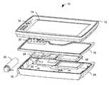
- FIG. 1illustrates an exploded view of a tablet computer assembly in accordance with an aspect of the present invention.
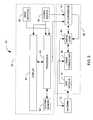
- FIG. 2illustrates a block diagram of an exemplary tablet computer assembly in accordance with an aspect of the present invention.
- FIG. 3illustrates a schematic block diagram of an exemplary implementation of a tablet computer assembly as part of a battlefield tactical network in accordance with an aspect of the present invention.
- FIG. 4illustrates an exemplary relay network in accordance with one or more aspects of the present invention.
- FIG. 5illustrates an exemplary display from a tablet computer in accordance with one or more aspects of the present invention.
- FIG. 6illustrates software architecture for an exemplary navigation and tracking software program operative on a tablet computer in accordance with one or more aspects of the present invention.
- FIG. 7illustrates power management states of an exemplary tablet computer assembly in accordance with one aspect of the present invention.
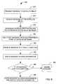
- FIG. 8illustrates an exemplary methodology for updating location data at a tablet computer in accordance with an aspect of the present invention.
- FIG. 9illustrates an exemplary methodology for the operation of a tablet computer in accordance with one or more aspects of the present invention.
- the present inventionrelates to systems and methods for utilizing one or more tablet computers in a communications network.
- a tablet computercan be in the form of tablet, a laptop, notebook computer or other portable computing device.
- the tablet computersincorporate L-band transceivers and GPS modules to allow automated communication of position data to and from other portable communications devices within the communications network.
- Each tablet computercan contain geographic information and appropriate software for viewing and manipulating the position data and the geographic information.
- the tablet computerscan also include the capacity for broadcasting text messages, either with or without position data associated with the tablet. These messages can include preset messages, such as a request for supporting fire or a hazardous materials warning, or they can simply be a free-text message composed on a touchscreen keyboard.
- the tablet computercan comprise one element of a vehicle communications system within a tactical network.
- the tablet computercan be mounted to a mount within the vehicle interior to serve as a display for a communications system within the vehicle.
- One or more portscan be made available within the tablet for electrically connecting to vehicle components to receive power or exchange data.
- the tablet computercan also be removed from the vehicle at need to provide a self-contained dismount communications system compatible with the tactical network.
- the tablet computer assemblycan be made modular to allow replacement of obsolete portions of the assembly without incurring significant reengineering costs.
- a suitable tablet computer assemblycan be adapted from a commercially available tablet computer. Converting an existing tablet computer requires the addition of one or more new computer boards as part of a transceiver module and an antenna to interface with GPS and L-band communications satellites.
- the transceiver modulecomprises three board assemblies.
- the three boardsinclude an RF transceiver assembly containing circuitry for L-band communications, an amplifier board that contains amplifiers necessary for transmitting and receiving L-band and GPS signals, and a digital board that includes a GPS module for determining the location of the tablet and control circuitry for the GPS module and the transceiver.
- a major problem with incorporating additional boardsis the accumulation of heat from the amplifiers and other digital components in the proximity of the heat sensitive components, such as a central processing unit and one or more memory chips, within the tablet computer.
- an aluminum enclosurecan be added to enclose and support the additional circuit board assemblies.
- the enclosureprovides both a mechanical interface for the transceiver module and support for the satellite antenna.
- the enclosurealso acts as a Faraday cage, which shields the internal circuitry from unwanted electromagnetic interference (EMI) radiating from external devices and the tablet computer.
- EMIelectromagnetic interference
- the tablet computercan be connected to the transceiver module through hardwired circuitry or an expansion board.
- the connection to the transceiver modulepasses through filters installed in the lid of the Faraday cage.
- the design approachis modular, enabling quick replacement of damaged components, with minimal invasion to the tablet computer.
- Internal metal shielding with the Faraday cageprovides additional protection to the RF and amplifier assemblies from both the tablet computer and the other circuit boards within the transceiver module.
- the present designovercomes previous problems in isolating the interference caused by normal antenna radiation patterns and internal RF emissions, which previously had interfered with the proper functioning of the compact satellite communications devices.
- FIG. 1illustrates an exploded view of a tablet computer assembly 10 in accordance with an aspect of the present invention.
- a control module 12comprises a processor (not shown) and a display 14 .
- the control moduleis a commercially available tablet computer, with various protective measures included to allow the tablet to withstand extreme conditions.
- the control module 12can comprise one or more integrated input devices (e.g., 16 ) such as keypads, trackballs, and touchscreens. Alternatively, user input may be provided with an external input device through one or more input ports (not shown).
- the control module 12is fitted with a back plate 18 .
- This back plate 18includes an opening 20 to admit one or more data communication connections and a power supply cable between a digital board 22 and the control module 12 .
- a Faraday cage 24comprising a metallic enclosure mounted to the back portion of the control module 12 , protects various RF circuit board components 26 and 28 from electromagnetic interference, such that the Faraday cage forms the rear portion of the tablet computer assembly 10 .
- the back plate 18comprises one wall of the Faraday cage 24 .
- the digital board 22contains control circuitry for an RF transceiver assembly 26 and a GPS module 28 .
- the RF transceiver assembly 26operates within the L-band of the electromagnetic spectrum.
- the Faraday cage 24comprises a metallic enclosure that substantially encompasses both the RF transceiver assembly 26 and the GPS module 28 to protect the transceiver and the GPS module from external electromagnetic interference.
- the control module 12is operatively connected to the RF transceiver assembly 26 and the GPS module 28 through the digital board 22 , such that the control module 12 can receive information from the transceiver and GPS module and submit commands to control their operation.
- the tablet computer assemblyfurther comprises an input/output board (not shown) that regulates the data connection between the control module 12 and the digital board 22 .
- the Faraday cage 24is an aluminum enclosure that serves as a heat sink that directs heat from the RF transceiver assembly 26 away from sensitive electrical components within the digital board 22 and the control module 12 .
- the RF transceiver assemblycan include additional metal shielding to reduce electromagnetic interference from components within the Faraday cage as well as to provide additional protection against exterior sources of interference.
- An antenna mount 30 operatively connected to the RF transceiver assembly 26extends through the Faraday cage 24 .
- the antenna mount 30includes a connector designed to mate with a similar connector on a detachable antenna 32 .
- the antenna mount 30allows signals to pass between the antenna 32 and the RF transceiver assembly and the GPS module 28 .
- the antenna 32is designed to allow transmission of signals at an L-band frequency to one or more satellite relays, and to receive transmissions on both the L-band and the various GPS frequencies (e.g., L1 and L2).
- the antenna 32can be separated from the tablet computer assembly 10 , to increase the compactness of the tablet computer assembly 10 .
- the antenna 32is a quadrifilar helix antenna.
- FIG. 2illustrates a block diagram of an exemplary tablet computer assembly 50 in accordance with one aspect of the present invention.
- the tablet computer 50includes a control module 52 that is operatively connected to a transceiver module 54 .
- the control module 52includes a display 56 that provides received messages and other data to a user.
- the display 56can include touchscreen capabilities, through an associated stylus, for example, to double as an input device for the user.
- one or more input devices 58can be provided, such as a miniature keyboard, a mouse, a microphone, or any of a number of other suitable devices for inputting commands.
- the input devices 58may be integrated into the tablet computer, or they can be provided for attachment to one or more input ports on the tablet.
- the tablet computerincludes an integrated microphone and one or more speakers for audio recording and playback.
- the control modulefurther includes a processor 60 that processes user input and messages received at the transceiver 54 .
- the processor 60produces messages for broadcast at the transceiver 54 in response to user input.
- the input devices 58can allow the user to select one of a plurality of predetermined messages.
- the usermay also enter free text or voice messages via an attached keyboard, microphone, or touchscreen.
- the processor 60will also process messages received at the transceiver module 54 to provide information to the user at the display 56 .
- the processor 60is operatively connected to a system memory 62 .
- the system memory 62can comprise any of a number of data storage mediums known in the art.
- the system memory 62comprises a block of random access memory (RAM) that serves as a working memory and a Secure Digital (SD) flash card that serves for data storage.
- the flash memorycan contain one or more software programs that provide and display geographic information concerning a particular area.
- the memorycan also include the known location of units of terrain, friendly figures, and enemy figures. This information can be updated periodically both through user input and through location update messages received at the transceiver module 54 .
- the system memory 62can also contain a log of messages and location updates received at the transceiver module 54 .
- the transceiver module 54comprises a digital logic board 66 , an RF transceiver assembly 68 , and a GPS module 70 .
- the digital logic board 66provides a control function for the transceiver 54 .
- the digital logic board 66can format messages to be sent by the transceiver 54 according to instructions from the control system 52 .
- the digital logic board 66can reformat received messages into a form acceptable at the control module 52 . This can include filtering and demodulating the messages, as well as other known signal processing techniques.
- the digital logic board 66is also responsible for the conversion of data between analog and digital formats, where it is necessary.
- the digital logic board 66can include an analog-to-digital converter and/or a digital-to-analog converter for digital sampling.
- the GPS module 70provides position information to be included in broadcast messages.
- one of the predetermined messages available for user selectioncan be a request for evacuation and medical assistance.
- the GPS module 70can provide location information for the requesting unit, so the information can be automatically include in the call for assistance.
- the location information for the unitwill be automatically broadcast to one or more other portable communications devices (not shown) over a tactical network.
- the RF transceiver assembly 68contains the hardware components necessary for the communications functions of the transceiver module 54 . These hardware components are located on one or more circuit boards comprising the RF transceiver assembly.
- the RF assembly 68can include an IF (intermediate frequency) board with frequency tuning circuitry for upmixing signals from the digital logic board 66 for transmission and for downmixing received signals to appropriate frequencies for processing, as well as an amplifier board with one or more amplifiers.
- the RF transceiver assembly 68can include appropriate shielding to prevent interference with the processing by external electrical and magnetic fields. For example, portions of the RF transceiver assembly 68 can be encompassed by a Faraday cage to reduce external electromagnetic interference.
- the antenna 72can be an integral part of the tablet computer assembly 50 , but in an exemplary implementation, the antenna 72 is detachable to increase the compactness of the tablet.
- the antenna 72can be capable of receiving signals of multiple frequencies, including L-band transmissions and global positioning signals.
- the antenna 72can assume any of a number of configurations designed to enable long-range transmission of RF signals at minimal power. In an exemplary implementation, the antenna has a helical configuration stretching over a length of approximately four inches.
- An input/output conversion card 76regulates the logic and power connections between the control module 52 and the transceiver module 54 .
- the input/output conversion card 76can regulate a power supply voltage to the transceiver module 54 via a DC-to-DC converter that produces an appropriate supply voltage from a power supply 78 associated with the control device 52 .
- the input/output conversion card 76can also regulate the logic level of signals passing between the control device 52 and the transceiver module 54 .
- the input/output conversion card 76can comprise a voltage regulator for converting a logic signal at a first characteristic voltage into a logic signal at a second characteristic voltage.
- FIG. 3illustrates an exemplary implementation of a tablet computer assembly 100 in accordance with an aspect of the present invention.
- the tablet computer assembly 100is a dismount portion of a vehicle communications system within of a battlefield tactical network that shares location information among a plurality of mobile and portable communications systems.
- the tablet computer assembly 100 of the exemplary implementationcan be mounted to the interior of a vehicle to provide communications capability to an occupant of the vehicle. When the occupant departs the vehicle, the tablet computer assembly can be removed to provide a portable communications assembly.
- the tablet computer assembly 100 of the present inventionis not limited to this use and can be used in a variety of applications requiring compact communications and navigation devices.
- the tablet computer assembly 100includes a control portion 102 that processes information to display to a user and receives user input and a transceiver module 104 allows the tablet computer 100 to communicate with one or more other communications devices.
- An input/output board 106 within the transceiver module 104regulates power and logic connections between the control module 102 and the transceiver module 104 .
- control module 102is part of a tablet computer adapted to provide control logic to the transceiver 104 module.
- These adaptationscan include providing the tablet computer with additional control software as well as hardware changes. For example, a connection to a power supply associated with the tablet computer may be provided to power the transceiver 104 .
- control logic from the tablet computercan be routed through a serial port to allow for more efficient connectivity with the transceiver.
- the control module 102includes a display 108 that provides information to a user.
- the display 108is a touch sensitive display that doubles as a touchscreen input for the tablet computer assembly 100 .
- the control module 102can include one or more other connections 110 for the addition of external input devices, such as keyboards, trackballs, and similar devices.
- a central processing unit 112receives communication requests as input from the display 108 and encodes each request as a message readable by the transceiver module 104 . The processor 112 then provides the encoded request to the transceiver module 104 through the input/output board 106 .
- the processor 112also generates a map image on the display 108 based on data stored on a flash card 114 and a random access memory (RAM) 116 .
- the RAM 116is a block of synchronous dynamic random access memory (SDRAM).
- SDRAMsynchronous dynamic random access memory
- the RAM 116can include messages recently received at the transceiver module 104 , such as position updates for friendly and enemy units. Received messages can be queued within the RAM 116 for a time and then written to the flash card 114 for later reference.
- the flash card 114can also include geographic data concerning an area of interest and the locations of various items of interest.
- the flash card 114can also contain software allowing the user can manipulate the displayed map via the touchscreen display or an external input device.
- the transceiver module 104comprises a digital board 118 and an RF board 120 .
- the transceiver module 104also includes a mount for a detachable antenna 122 .
- the digital board 118includes a transceiver control 124 that handles network protocol for communications with the tactical network.
- the transceiver control 124also provides an application programming interface to external applications.
- the digital board 118further comprises a modulator/demodulator 126 that translates between the baseband signal associated with the transceiver control 124 and the intermediate frequency associated with the a frequency converter 128 on the RF board 120 .
- the modulator/demodulator 126comprises a field programmable gate array (FPGA) configured to provide the acquisition of a forward channel from the tactical network and to track the signal within that channel. After acquiring and tracking the signal from the forward channel, the FPGA decodes the forward error correction information coded into the data and provides the signal information to the transceiver control 124 for further processing.
- FPGAfield programmable gate array
- the FPGAreceives encoded network layer bits from the processor and provides link and physical layer processing to produce an intermediate frequency signal. The intermediate frequency signal is then provided to the RF assembly 120 for upconversion and transmission.
- An analog-to-digital converter 130is provided to digitally sample incoming signals and provide the samples to the modulator/demodulator 126 .
- the digital board 118further includes a GPS module 132 that determines the location of the tablet computer assembly 100 upon a command from the processor 112 .
- the GPS module 132receives radio frequency input directly from the RF board 120 via a coaxial connector split off from the signal path.
- the present location of the tablet computer assembly 100can be determined from this input as is known in the art.
- the generated location informationis made available to the transceiver control 124 for inclusion in outgoing location update messages to the tactical network.
- the RF assembly 120comprises an IF board 134 and an HPA/LNA amplifier assembly 135 .
- the IF boardincludes a frequency converter 128 .
- the amplifier assemblyincludes a high power amplifier 136 , a low noise amplifier 137 , and a switch 138 that switches the RF assembly 120 between a transmit and a receive state.
- the frequency converter 128upconverts a modulated intermediate frequency signal provided by the modulator/demodulator 126 to a radio frequency and provides it to a high power amplifier 136 via the switch 138 .
- the amplified signalis then provided to the antenna 122 for transmission.
- the antenna 122is a detachable quadrifilar helix antenna operative to receive both L-band frequencies and the frequencies associated with global position systems (e.g., L1 and L2).
- a signalis received at the antenna 122 and amplified at a low noise amplifier 137 .
- the amplified radio frequency signalis passed through the switch 138 to the frequency converter 128 for down conversion to an intermediate frequency.
- the components of the RF board 120are enclosed in a Faraday cage (not shown) to reduce electromagnetic interference with the transmitted and received RF signals.
- the transceiver module 104is powered by an internal power supply 140 associated with the control module 102 .
- the internal power supply 140comprises one or more rechargeable batteries generating between sixteen and twenty-five volts.
- the assemblycan be electrically connected to a vehicle power supply 142 to continuously recharge the internal power supply 140 .
- An electrical connectioncan be made available through a power supply port (not shown) on the control module 102 to allow an electrical connection between the internal power supply 140 and the vehicle power supply 142 .
- the power supply voltageis provided to a DC-to-DC converter 144 on the I/O board 106 , which converts the voltage down to a necessary voltage for the transceiver module 104 .
- the transceiver module 104requires a power supply within a range of ten to about fourteen and a half volts, and the DC-to-DC converter 144 provides a twelve-volt supply to the transceiver 104 .
- the specific voltage levels experienced by the DC-to-DC convertercan be adjusted according to the respective power requirements of the control module 102 and the transceiver 104 .
- the I/O board 106further includes a voltage regulator 146 that standardizes the voltage level of the logic signals passing between the control module 102 and the transceiver module 104 .
- the control module 102operates at a voltage of five volts, but the transceiver module 104 requires logic signals at 3.3 volts.
- the voltage regulator 146converts the five-volt logic of the control module into the 3.3 volt logic appropriate for the transceiver.
- the transceiver module 104can be adapted to accept logic signals at the same voltage as the control module 102 , rendering the voltage regulator 146 unnecessary.
- FIG. 4illustrates an exemplary communications system 150 in accordance with one or more aspects of the present invention.
- the exemplary communications system 150comprises a tablet computer 152 in accordance with an aspect of the present invention, as well as a plurality of other communications devices 154 - 160 , operative at least to transmit and receive text messages and location information among themselves.
- These communications devicescan include portable communications devices 154 , for dismounted soldiers, mobile communications devices 156 , such as those found in vehicle units, and stationary communications platforms 158 and 160 , as might be expected in a command center.
- the communications system 100facilitates transmissions between communications devices 154 - 160 at reduced power requirements, thus extending the useful life of batteries in portable and mobile units while also reducing the size and weight of associated power supplies.
- the communications system 150further comprises a relay network comprising a plurality of relays (e.g., 164 and 166 ) that are arranged to relay messages over a predetermined coverage area.
- the relay networkcan include ground installations, spacecraft, and other appropriate relay platforms.
- the relayse.g., 164 and 166
- the relaysare operative to receive transmissions from a tablet computer 152 and to re-broadcast the transmissions at the same or boosted power levels to communications devices (e.g., 154 - 160 ) within the coverage area.
- the transmissionscan be passed along the relay network until an appropriate relay (e.g., 166 ) is found to re-broadcast the transmission to one or more intended recipients.
- a location update messageis provided by a tablet computer 152 .
- the messagecan contain a geographic location, expressed in a standard set of coordinates, a unique identification string for the tablet computer 152 , and any necessary error coding or routing information. Any of a variety of encryption mechanisms (e.g., hashing, key pairs) can be employed to encrypt the message for security purposes.
- the generated messageis multicast by the tablet computer as an analog signal.
- the transmitted messageis received at a relay 164 within the relay network.
- the relay 164will analyze the routing information within the signal and determine one or more appropriate relays within the network to re-broadcast the signal, as o make it available to the intended recipients of the message.
- the analog signalis sent to and re-broadcast by one or more appropriate relays (e.g., 166 ) at increased power levels so as to reach the intended recipients within the coverage area.
- the relay networkcan consist of terrestrial relays as well as spacebound relays.
- signals from a satellite relaye.g., 166
- a land-based Ethernet connection 170can be provided to carry signals to a second stationary communications platform 160 outside of the coverage area of the satellite relays
- the relayed signalis received at one or more communication devices (e.g., 154 - 162 ) within the tactical network.
- the signalis processed to produce updated position data for the transmitting tablet computer 154 .
- This processingcan include filtering and demodulating the signal, as well as decrypting the transmitted message and identifying the originating communication device (i.e., the tablet computer 152 ).
- the messageis stored in memory and provided to a processor within the receiving device (e.g., 156 ).
- the processorprovides appropriate input to an associated display to update the position of the originating communications device 152 .
- FIG. 5illustrates an exemplary display 200 from a tablet computer in accordance with one or more aspects of the present invention.
- the displayshows a map 202 of an area, including elements of the terrain, such as rivers 204 , roads 206 , bridges 208 , and wooded areas 210 .
- the map 202may also include a compass 212 and a legend 214 to assist with reading the map.
- the system memorycan include location information 216 (e.g., longitude, latitude) from a global positioning module to allow the various elements of terrain to be presented on the map relative to the position 218 of the tablet computer.
- the positions of friendly 220 and enemy units 222may also be represented on the map on the tablet computer.
- the positions of friendly 220 and enemy units 222can be provided, for example, via periodic updates to the tablet computer.
- the respective locations of enemy unitscan be determined by soldiers on the ground and broadcast from a portable communication device as a location update. This allows the user of the tablet computer to be aware of the locations of both friendly and hostile units and react accordingly.
- the display 200includes one or more scroll bars 226 for controlling the positioning of the map 202 .
- the perspective, or zoom, of the mapcan be controlled either by one or more touchscreen buttons 228 on the display 200 or by a drop-down menu 230 that allows the user to set a preferred perspective.
- the displayalso includes the global position 216 (e.g., longitude and latitude) of the tablet computer, the battery status 232 and the current time 234 .
- the global position information and timecan be provided by a GPS module.
- the display 200further includes a plurality of drop down menus.
- a message drop down menu 236allows a user to choose from a list of message options. These entry options can include a number of preset messages.
- the NBC1 optioncan be used to instantly send a message indicating the presence of nuclear, biological, or chemical weapons along with a location obtained from the GPS module.
- the SPOT optionallows for automated reporting of the location of enemy troops.
- the type (e.g., artillery, infantry, etc.) and approximate number of the enemy troopscan be entered at a menu along with an estimate of their location.
- the Medical Evacuation and Check Fire commandswork similarly, broadcasting a request for assistance from the user with location data for the tablet computer.
- Free textcan be entered via an attached keyboard, or as part of an on-screen keyboard accessible via an appropriate input device, such as a touchscreen or a mouse.
- free-text messagescan be assigned a destination device by the user. For example, it might be desirable to send a free-text message only to the commander of a particular unit.
- the free-text messaging functioncan include a drop-down menu that allows the commander to be chosen as a recipient, as well as an option for excluding personnel below a particular rank.
- a zoom drop-down menu 230allows the user to select a zoom perspective for the displayed map.
- a filter menu 238allows filters to be applied to the map image.
- the map 202can be filtered to display only enemy units.
- the mapcan be filtered to show only units of a certain type, such as infantry or artillery. It will be appreciated that the filters can include other functions, and need not be limited to the above.
- An options menu 240allows a user to determine the network status, review logged messages, and change any necessary settings on the navigation and tracking software. It is to be appreciated that the information presented in FIG. 5 is exemplary only, and that more or less information could be presented on one or more screens in similar or different manners.
- FIG. 6illustrates software architecture 300 for an exemplary navigation and tracking program operative to run on a tablet computer in accordance with one or more aspects of the present invention.
- the illustrated software architecture 300operates in conjunction with a standard operating system designed for use in a mobile computing environment.
- the various functions performed by the described softwarecan include functions or routines provided with the operating system.
- the operating systemcan provide routines for accepting input at an input device.
- the software architectureoperates in conjunction with a Windows CE operating system.
- the Windows CE operating systemprovides device drivers for the various input devices associated with the tablet computer, network protocols, and general object handling protocols.
- a start-up routine 302initializes the software architecture 300 when the navigation and tracking software is started.
- the start-up routine 302can be called as part of the overall start-up process of the tablet computer's operating system, such that the navigation and tracking software is initiated upon powering up the tablet computer.
- the start-up routine 302can reset all objects and classes associated with the software architecture to an appropriate initial state and prepare a location associated with a working memory within the tablet computer to receive location data and text messages.
- the start-up routine 302can include a start-up sequence of commands, such as a command to display a map screen at a particular level of detail, broadcast a location update giving the present position of the tablet, and update the location of the tablet on the map.
- a user interface routine 304formats data from other software routines within the architecture 300 to be shown on a display (not shown). For example, location data associated with the tablet computer can be obtained via a GPS module 306 on the tablet.
- a GPS interface routine 308interprets the GPS module 306 and provides the data to the user interface routine 304 in a usable form. The GPS interface routine 308 also drives the GPS module 306 periodically to produce updated location data according to a predetermined update schedule.
- the user interface routine 304is responsive to commands from an input device, such as a touchscreen keypad. This can include commands to adjust the display of data, to generate a message for an associated transceiver 310 , or to initiate a tablet destruct routine 312 that completely erases and destroys the device memory.
- the tablet computer assemblycan contain security protocols besides the memory destruction of the tablet destroy routine 312 .
- the tablet computer assemblycan include remote challenge protocols, remote lockout protocols, remote memory destruction, and remote re-keying of the L-band SATCOM transceiver from a central station.
- the user interface routine 304When a command is received requiring the broadcast of a message at the transceiver, the user interface routine 304 provides the command to a message processing routine 312 .
- the message processing routine 312generates an appropriate message according to the user command and provides the message to a transceiver interface routine 314 .
- the message processing routinecan also generate automated messages according to a predetermined schedule.
- the generated messagecan include location data provided from the user interface process 304 as well as appropriate encryption.
- the message processing routine 312decrypts the message, logs it to a memory, and assigns a time and date stamp to the message. Any text or position data provided within the message is then extracted and provided to the user interface routine 304 to be displayed to the user.
- the transceiver interface routine 314interfaces with the control circuitry of the transceiver 310 to drive the processor to broadcast messages from the message processing routine 312 .
- the transceiver interfacecan drive the transceiver to error code a message and modulate to a radio frequency signal. The message is then amplified and broadcast over an associated antenna.
- the transceiver interface routine 314also oversees the demodulation and error checking of messages received at the transceiver 306 . Once the message is demodulated and checked for error, it is passed to the message processing routine 312 .
- FIG. 7illustrates power management states 320 of an exemplary tablet computer assembly in accordance with one aspect of the present invention. Extending the effective battery life of the tablet computer to useful levels requires careful management of power resources within the tablet computer, the transceiver, and the GPS module. Accordingly, each of the tablet computer, the transceiver, and the GPS module can be controlled by one or more customized software applications running at the tablet computer or the digital board to alternate between various states of activity and power consumption.
- the softwarecan transition the tablet to a state of lower power consumption, such as a blank display condition, when it has not received input from a user for a predetermined period.
- the transitionscan also be instigated directly by user input at a graphical user interface on the tablet.
- the graphical user interfacecan display an estimate of the remaining battery power for the device to guide the user in determining an appropriate power consumption state for the tablet, the transceiver, and the GPS module.
- the tabletcan produce visual and audible alerts when the battery level reaches one or more predetermined levels.
- the tabletwhen it is displaying or receiving information, it remains in a Tablet On mode 322 .
- the tabletIn the On mode 322 , the tablet can display geographical information and received location updates, receive additional location updates from the transceiver and the GPS module, and process message requests from the user.
- the tabletWhen the tablet has been idle for a set period of time, the tablet will enter a Stand-by mode 324 .
- the tablet stand-by mode 324the tablet will blank its display until it receives input the user.
- the tabletcan transition from Stand-by mode 324 to On mode 322 when it receives input from the GPS module, or the transceiver, providing an audible alert to the user that updated information is available.
- the lowest power consumption stage for the tabletis the Tablet Off mode 326 .
- the Off mode 326can be selected by a user or automatically selected after a predetermined idle period for the tablet. As the name would suggest, in the Off mode 326 , the tablet cannot display or receive information or receive user input until it is restarted. Position updates and text messages received during the tablet Off mode will not be stored at the tablet, but in an exemplary embodiment, incoming messages can be cached at the transceiver control hardware until the tablet is reactivated.
- the transceiveris also controlled by circuitry, and can be transitioned through its power management stages by control software at the transceiver as well as the tablet software.
- the transceivergenerally remains within a Keep Alive mode 328 until it is necessary to receive or transmit data.
- the transceiverconsumes a minimal amount of power to monitor the antenna for incoming signals and to maintain memory in power sensitive applications within the transceiver control.
- the transceiveronly transmits data at a user command and at predefined intervals, so the transceiver will generally spend a majority of its operation at the Keep Alive mode 328 .
- the transceiveris switched to an On mode 330 when it is actively transmitting and receiving data. This can be the result of user intervention (e.g., a message request) or automated processes within the control software of the tablet and the transceiver (e.g., a scheduled location update transmission).
- the transceivercan also be switched to an ON mode 330 in response to an incoming transmission.
- a transceiver off mode 332can be selected by the user or by a control process for situations requiring extreme power conservation. While in the Off mode, the transceiver cannot send or receive messages and can lose queued data stored in memory within the transceiver control circuitry.
- the GPSis controlled through GPS power cycling software at the GPS module and has three primary power modes 336 , 338 , and 340 , as well as an Off stage 342 .
- the GPShas normal functionality. In other words, the GPS module determines the location of the tablet and provides this information to the tablet.
- the GPS moduleremains in a Stand-By mode 338 between periodic position updates. As it is only necessary to update the location data for the tablet information at periodic intervals (e.g., every 150 seconds), the GPS module In the Stand-by mode 338 , the GPS module does not actively acquire position data, but maintains a ready state to conduct periodic updates of the device position.
- the third primary power modeis a Keep Alive mode 340 .
- the Keep Alive modehas the lowest power consumption of the three primary power modes.
- the Keep Alive modeprovides enough power to retain data stored in nonvolatile memory, such as almanac data, cryptography parameters, operator entered data, the current time, the last recorded position, and similar data.
- a GPS off mode 342can be selected by the user or by a GPS control process for situations requiring extreme power conservation. While in the Off mode 342 , the GPS cannot send or receive messages and will lose any stored initialization data in memory. It would thus be necessary for the GPS module to repeat the “first fix” initialization process when reactivated.
- FIGS. 8 and 9methodologies in accordance with various aspects of the present invention will be better appreciated with reference to FIGS. 8 and 9 . While, for purposes of simplicity of explanation, the methodologies of FIGS. 8 and 9 are shown and described as executing serially, it is to be understood and appreciated that the present invention is not limited by the illustrated order, as some aspects could, in accordance with the present invention, occur in different orders and/or concurrently with other aspects from that shown and described herein. Moreover, not all illustrated features may be required to implement a methodology in accordance with an aspect the present invention.
- FIG. 8illustrates an exemplary methodology 350 for updating information associated with a portable communications device at a tablet computer in accordance with an aspect of the present invention.
- the methodologybegins at 352 wherein a message is sent from a portable communications device to a satellite relay.
- the messagecan contain any or all of location data for the device, a unique identification for the device, a text message, and routing information to ensure that the message is received only by an associated plurality of portable communication systems.
- the satellite relaycomprises part of a relay network establishing a communication coverage area.
- the messageis received at the satellite network.
- routing information within the messageis processed to determine which of a plurality of relay points within the relay network should rebroadcast the message to the associated plurality of portable communication devices.
- the friendly communication unitscan include tablet computers intended for dismounted units in accordance with the present invention, as well as larger tactical systems within vehicles and stationary encampments.
- One or more selected relayscan re-broadcast the message at a power level substantially larger than the received message signal to increase the coverage area of the tactical communication system.
- the messageis multicast at the one or more selected relay points.
- the rebroadcast messageis received at the tablet computer.
- the messageis checked for routing data at 362 , and at 364 , the tablet computer determines if the message is intended for the tablet computer. If not, the methodology advances to 366 where the message is ignored. If the message is intended for the tablet computer, the methodology advances to 368 , where the display of the tablet computer and the system memory are updated to reflect the information from the message. For example, if the message includes location data, the system memory will be changed to reflect the new position of the originating object will be moved relative to the map on the display. If the message includes a text message, the message will be logged in the memory, and the message will be displayed at the screen of the tablet computer.
- FIG. 9illustrates an exemplary methodology 450 for the operation of a tablet computer assembly in accordance with one or more aspects of the present invention.
- the methodology 450begins at 452 , with a transceiver module associated with the tablet computer assembly in a low power, or sleep mode.
- the methodologycontinues at 454 , where the tablet computer determines if any message request has been input by a user. For example, the user can request that the assembly send a preset message to a relay network requesting assistance. If a request has been received, the tablet computer assembly generates and broadcasts the requested message at 456 . The methodology then proceeds to 458 . If no request is received from the user, the methodology proceeds directly to 458 .
- the tablet computer assemblydetermines if any incoming messages have been received.
- a received messagecould be a position report updating the position of a friendly unit, a spot report giving the present location of an enemy unit, or a text message from one of a plurality of portable communications devices within a logical network associated with the tablet computer assembly. If an incoming message has been received, the tablet computer processes the incoming message at 460 and updates a memory and a display associated with the tablet computer to reflect the message data, and the methodology advances to 462 . If no messages have been received, the methodology proceeds directly to 462 .
- the tablet computerdetermines if a first, predetermined interval of time has elapsed. At the end of this interval, the tablet computer assembly updates its location information using a GPS module. In an exemplary embodiment, the first interval has a length of two and one-half minutes. If it is necessary to update the GPS location information, the transceiver module enters a GPS receiver mode at 464 . In the GPS receiver mode, the transceiver module sends received L1 and L2 signals directly to a GPS module for analysis. The methodology then continues to 466 , where the GPS module analyzes the received signals to determine the present location of the tablet computer assembly. This can be accomplished by any of a number of means known in the art. The methodology then advances to 468 . If the first predetermined interval has not elapsed at 462 , the methodology proceeds directly to 468 .
- the tablet computerdetermines if a second, predetermined interval of time interval has elapsed, indicating that a situational awareness message should be broadcast to a relay network for multicast to one or more friendly units in the area. In an exemplary embodiment, this second interval has a length of five minutes. If the second interval has elapsed, the methodology advances to 470 , where the transceiver module enters an L-band transmission mode. At 472 , the transceiver broadcasts an L-band transmission to one or more friendly units through a relay network. This transmission will include the present position of the tablet computer assembly. The methodology then advances to 474 . If the second interval has not elapsed at 468 , the methodology advances directly to 474 . At 474 , the transceiver module resumes a low power mode. The methodology then returns to 452 to await user input or an incoming message.
Landscapes
- Engineering & Computer Science (AREA)
- Mechanical Engineering (AREA)
- Computer Networks & Wireless Communication (AREA)
- Signal Processing (AREA)
- Radar, Positioning & Navigation (AREA)
- Remote Sensing (AREA)
- Position Fixing By Use Of Radio Waves (AREA)
- Mobile Radio Communication Systems (AREA)
Abstract
Description
Claims (17)
Priority Applications (3)
| Application Number | Priority Date | Filing Date | Title |
|---|---|---|---|
| US10/634,295US7813876B2 (en) | 2003-08-05 | 2003-08-05 | Dismount tablet computer assembly for wireless communication applications |
| GB0417167AGB2406477B (en) | 2003-08-05 | 2004-08-02 | Dismount tablet computer assembly for wireless communication applications |
| AU2004203602AAU2004203602B2 (en) | 2003-08-05 | 2004-08-04 | Dismount tablet computer assembly for wireless communication applications |
Applications Claiming Priority (1)
| Application Number | Priority Date | Filing Date | Title |
|---|---|---|---|
| US10/634,295US7813876B2 (en) | 2003-08-05 | 2003-08-05 | Dismount tablet computer assembly for wireless communication applications |
Publications (2)
| Publication Number | Publication Date |
|---|---|
| US20050033513A1 US20050033513A1 (en) | 2005-02-10 |
| US7813876B2true US7813876B2 (en) | 2010-10-12 |
Family
ID=32962818
Family Applications (1)
| Application Number | Title | Priority Date | Filing Date |
|---|---|---|---|
| US10/634,295Expired - Fee RelatedUS7813876B2 (en) | 2003-08-05 | 2003-08-05 | Dismount tablet computer assembly for wireless communication applications |
Country Status (3)
| Country | Link |
|---|---|
| US (1) | US7813876B2 (en) |
| AU (1) | AU2004203602B2 (en) |
| GB (1) | GB2406477B (en) |
Cited By (1)
| Publication number | Priority date | Publication date | Assignee | Title |
|---|---|---|---|---|
| US10923869B2 (en)* | 2019-06-10 | 2021-02-16 | Toyota Motor Engineering & Manufacturing North America, Inc. | Vehicle harness connector interface assemblies |
Families Citing this family (122)
| Publication number | Priority date | Publication date | Assignee | Title |
|---|---|---|---|---|
| US6658091B1 (en) | 2002-02-01 | 2003-12-02 | @Security Broadband Corp. | LIfestyle multimedia security system |
| US11244545B2 (en) | 2004-03-16 | 2022-02-08 | Icontrol Networks, Inc. | Cross-client sensor user interface in an integrated security network |
| US11677577B2 (en) | 2004-03-16 | 2023-06-13 | Icontrol Networks, Inc. | Premises system management using status signal |
| US7711796B2 (en) | 2006-06-12 | 2010-05-04 | Icontrol Networks, Inc. | Gateway registry methods and systems |
| US11113950B2 (en) | 2005-03-16 | 2021-09-07 | Icontrol Networks, Inc. | Gateway integrated with premises security system |
| US12063220B2 (en) | 2004-03-16 | 2024-08-13 | Icontrol Networks, Inc. | Communication protocols in integrated systems |
| US10142392B2 (en) | 2007-01-24 | 2018-11-27 | Icontrol Networks, Inc. | Methods and systems for improved system performance |
| US11190578B2 (en) | 2008-08-11 | 2021-11-30 | Icontrol Networks, Inc. | Integrated cloud system with lightweight gateway for premises automation |
| US10237237B2 (en) | 2007-06-12 | 2019-03-19 | Icontrol Networks, Inc. | Communication protocols in integrated systems |
| US10156959B2 (en) | 2005-03-16 | 2018-12-18 | Icontrol Networks, Inc. | Cross-client sensor user interface in an integrated security network |
| US11489812B2 (en) | 2004-03-16 | 2022-11-01 | Icontrol Networks, Inc. | Forming a security network including integrated security system components and network devices |
| US9609003B1 (en) | 2007-06-12 | 2017-03-28 | Icontrol Networks, Inc. | Generating risk profile using data of home monitoring and security system |
| US10444964B2 (en) | 2007-06-12 | 2019-10-15 | Icontrol Networks, Inc. | Control system user interface |
| US10313303B2 (en) | 2007-06-12 | 2019-06-04 | Icontrol Networks, Inc. | Forming a security network including integrated security system components and network devices |
| GB2428821B (en) | 2004-03-16 | 2008-06-04 | Icontrol Networks Inc | Premises management system |
| US10348575B2 (en) | 2013-06-27 | 2019-07-09 | Icontrol Networks, Inc. | Control system user interface |
| US8963713B2 (en) | 2005-03-16 | 2015-02-24 | Icontrol Networks, Inc. | Integrated security network with security alarm signaling system |
| US10382452B1 (en) | 2007-06-12 | 2019-08-13 | Icontrol Networks, Inc. | Communication protocols in integrated systems |
| US10522026B2 (en) | 2008-08-11 | 2019-12-31 | Icontrol Networks, Inc. | Automation system user interface with three-dimensional display |
| US11159484B2 (en) | 2004-03-16 | 2021-10-26 | Icontrol Networks, Inc. | Forming a security network including integrated security system components and network devices |
| US9531593B2 (en) | 2007-06-12 | 2016-12-27 | Icontrol Networks, Inc. | Takeover processes in security network integrated with premise security system |
| US10721087B2 (en) | 2005-03-16 | 2020-07-21 | Icontrol Networks, Inc. | Method for networked touchscreen with integrated interfaces |
| US8635350B2 (en) | 2006-06-12 | 2014-01-21 | Icontrol Networks, Inc. | IP device discovery systems and methods |
| US11277465B2 (en) | 2004-03-16 | 2022-03-15 | Icontrol Networks, Inc. | Generating risk profile using data of home monitoring and security system |
| US11343380B2 (en) | 2004-03-16 | 2022-05-24 | Icontrol Networks, Inc. | Premises system automation |
| US20090077623A1 (en) | 2005-03-16 | 2009-03-19 | Marc Baum | Security Network Integrating Security System and Network Devices |
| US10200504B2 (en) | 2007-06-12 | 2019-02-05 | Icontrol Networks, Inc. | Communication protocols over internet protocol (IP) networks |
| US11316958B2 (en) | 2008-08-11 | 2022-04-26 | Icontrol Networks, Inc. | Virtual device systems and methods |
| US11201755B2 (en) | 2004-03-16 | 2021-12-14 | Icontrol Networks, Inc. | Premises system management using status signal |
| US9191228B2 (en) | 2005-03-16 | 2015-11-17 | Icontrol Networks, Inc. | Cross-client sensor user interface in an integrated security network |
| US11582065B2 (en) | 2007-06-12 | 2023-02-14 | Icontrol Networks, Inc. | Systems and methods for device communication |
| US8988221B2 (en) | 2005-03-16 | 2015-03-24 | Icontrol Networks, Inc. | Integrated security system with parallel processing architecture |
| US11916870B2 (en) | 2004-03-16 | 2024-02-27 | Icontrol Networks, Inc. | Gateway registry methods and systems |
| US11368429B2 (en) | 2004-03-16 | 2022-06-21 | Icontrol Networks, Inc. | Premises management configuration and control |
| US10339791B2 (en) | 2007-06-12 | 2019-07-02 | Icontrol Networks, Inc. | Security network integrated with premise security system |
| US20170118037A1 (en) | 2008-08-11 | 2017-04-27 | Icontrol Networks, Inc. | Integrated cloud system for premises automation |
| US9141276B2 (en) | 2005-03-16 | 2015-09-22 | Icontrol Networks, Inc. | Integrated interface for mobile device |
| US11811845B2 (en) | 2004-03-16 | 2023-11-07 | Icontrol Networks, Inc. | Communication protocols over internet protocol (IP) networks |
| US9729342B2 (en) | 2010-12-20 | 2017-08-08 | Icontrol Networks, Inc. | Defining and implementing sensor triggered response rules |
| US10375253B2 (en) | 2008-08-25 | 2019-08-06 | Icontrol Networks, Inc. | Security system with networked touchscreen and gateway |
| US9306809B2 (en) | 2007-06-12 | 2016-04-05 | Icontrol Networks, Inc. | Security system with networked touchscreen |
| US10999254B2 (en) | 2005-03-16 | 2021-05-04 | Icontrol Networks, Inc. | System for data routing in networks |
| US11496568B2 (en) | 2005-03-16 | 2022-11-08 | Icontrol Networks, Inc. | Security system with networked touchscreen |
| US11700142B2 (en) | 2005-03-16 | 2023-07-11 | Icontrol Networks, Inc. | Security network integrating security system and network devices |
| US20170180198A1 (en) | 2008-08-11 | 2017-06-22 | Marc Baum | Forming a security network including integrated security system components |
| US20110128378A1 (en) | 2005-03-16 | 2011-06-02 | Reza Raji | Modular Electronic Display Platform |
| US20120324566A1 (en) | 2005-03-16 | 2012-12-20 | Marc Baum | Takeover Processes In Security Network Integrated With Premise Security System |
| US11615697B2 (en) | 2005-03-16 | 2023-03-28 | Icontrol Networks, Inc. | Premise management systems and methods |
| US8296388B2 (en)* | 2005-07-18 | 2012-10-23 | Microsoft Corporation | Cross-application encoding of geographical location information |
| US20070042708A1 (en)* | 2005-08-16 | 2007-02-22 | Arinc Inc. | Systems and methods for voice and data communication |
| US20070042727A1 (en)* | 2005-08-16 | 2007-02-22 | Arinc Inc. | Systems and methods for voice and data communication |
| US20070050183A1 (en)* | 2005-08-26 | 2007-03-01 | Garmin Ltd. A Cayman Islands Corporation | Navigation device with integrated multi-language dictionary and translator |
| US8194585B2 (en)* | 2005-11-28 | 2012-06-05 | OMNI-WiFi, LLC. | Wireless communication system |
| US7515576B2 (en)* | 2006-01-31 | 2009-04-07 | Microsoft Corporation | User interface and data structure for transmitter fingerprints of network locations |
| US7885668B2 (en)* | 2006-01-31 | 2011-02-08 | Microsoft Corporation | Determining the network location of a user device based on transmitter fingerprints |
| US8145719B2 (en)* | 2006-03-03 | 2012-03-27 | Gogroups | Method and system for messaging and communication based on groups |
| US10079839B1 (en) | 2007-06-12 | 2018-09-18 | Icontrol Networks, Inc. | Activation of gateway device |
| US12063221B2 (en) | 2006-06-12 | 2024-08-13 | Icontrol Networks, Inc. | Activation of gateway device |
| US11706279B2 (en) | 2007-01-24 | 2023-07-18 | Icontrol Networks, Inc. | Methods and systems for data communication |
| US7633385B2 (en) | 2007-02-28 | 2009-12-15 | Ucontrol, Inc. | Method and system for communicating with and controlling an alarm system from a remote server |
| US7640105B2 (en) | 2007-03-13 | 2009-12-29 | Certus View Technologies, LLC | Marking system and method with location and/or time tracking |
| US8060304B2 (en)* | 2007-04-04 | 2011-11-15 | Certusview Technologies, Llc | Marking system and method |
| US8451986B2 (en) | 2007-04-23 | 2013-05-28 | Icontrol Networks, Inc. | Method and system for automatically providing alternate network access for telecommunications |
| US11316753B2 (en) | 2007-06-12 | 2022-04-26 | Icontrol Networks, Inc. | Communication protocols in integrated systems |
| US10523689B2 (en) | 2007-06-12 | 2019-12-31 | Icontrol Networks, Inc. | Communication protocols over internet protocol (IP) networks |
| US12283172B2 (en) | 2007-06-12 | 2025-04-22 | Icontrol Networks, Inc. | Communication protocols in integrated systems |
| US11646907B2 (en) | 2007-06-12 | 2023-05-09 | Icontrol Networks, Inc. | Communication protocols in integrated systems |
| US11237714B2 (en) | 2007-06-12 | 2022-02-01 | Control Networks, Inc. | Control system user interface |
| US10423309B2 (en) | 2007-06-12 | 2019-09-24 | Icontrol Networks, Inc. | Device integration framework |
| US10051078B2 (en) | 2007-06-12 | 2018-08-14 | Icontrol Networks, Inc. | WiFi-to-serial encapsulation in systems |
| US11212192B2 (en) | 2007-06-12 | 2021-12-28 | Icontrol Networks, Inc. | Communication protocols in integrated systems |
| US11423756B2 (en) | 2007-06-12 | 2022-08-23 | Icontrol Networks, Inc. | Communication protocols in integrated systems |
| US10389736B2 (en) | 2007-06-12 | 2019-08-20 | Icontrol Networks, Inc. | Communication protocols in integrated systems |
| US10666523B2 (en) | 2007-06-12 | 2020-05-26 | Icontrol Networks, Inc. | Communication protocols in integrated systems |
| US12003387B2 (en) | 2012-06-27 | 2024-06-04 | Comcast Cable Communications, Llc | Control system user interface |
| US12184443B2 (en) | 2007-06-12 | 2024-12-31 | Icontrol Networks, Inc. | Controlling data routing among networks |
| US10498830B2 (en) | 2007-06-12 | 2019-12-03 | Icontrol Networks, Inc. | Wi-Fi-to-serial encapsulation in systems |
| US11601810B2 (en) | 2007-06-12 | 2023-03-07 | Icontrol Networks, Inc. | Communication protocols in integrated systems |
| US11089122B2 (en) | 2007-06-12 | 2021-08-10 | Icontrol Networks, Inc. | Controlling data routing among networks |
| US10616075B2 (en) | 2007-06-12 | 2020-04-07 | Icontrol Networks, Inc. | Communication protocols in integrated systems |
| US11218878B2 (en) | 2007-06-12 | 2022-01-04 | Icontrol Networks, Inc. | Communication protocols in integrated systems |
| US10223903B2 (en) | 2010-09-28 | 2019-03-05 | Icontrol Networks, Inc. | Integrated security system with parallel processing architecture |
| US11831462B2 (en) | 2007-08-24 | 2023-11-28 | Icontrol Networks, Inc. | Controlling data routing in premises management systems |
| US11916928B2 (en) | 2008-01-24 | 2024-02-27 | Icontrol Networks, Inc. | Communication protocols over internet protocol (IP) networks |
| DE102008008502B4 (en)* | 2008-02-11 | 2014-08-14 | Siemens Aktiengesellschaft | Arrangement for controlling an antenna arrangement in a magnetic resonance apparatus |
| US8290204B2 (en) | 2008-02-12 | 2012-10-16 | Certusview Technologies, Llc | Searchable electronic records of underground facility locate marking operations |
| US8532342B2 (en)* | 2008-02-12 | 2013-09-10 | Certusview Technologies, Llc | Electronic manifest of underground facility locate marks |
| US8672225B2 (en) | 2012-01-31 | 2014-03-18 | Ncr Corporation | Convertible barcode reader |
| US8249306B2 (en)* | 2008-03-18 | 2012-08-21 | Certusview Technologies, Llc | Virtual white lines for delimiting planned excavation sites |
| CA2707246C (en)* | 2009-07-07 | 2015-12-29 | Certusview Technologies, Llc | Automatic assessment of a productivity and/or a competence of a locate technician with respect to a locate and marking operation |
| US8280117B2 (en) | 2008-03-18 | 2012-10-02 | Certusview Technologies, Llc | Virtual white lines for indicating planned excavation sites on electronic images |
| US20170185278A1 (en) | 2008-08-11 | 2017-06-29 | Icontrol Networks, Inc. | Automation system user interface |
| US8280631B2 (en)* | 2008-10-02 | 2012-10-02 | Certusview Technologies, Llc | Methods and apparatus for generating an electronic record of a marking operation based on marking device actuations |
| US8620587B2 (en)* | 2008-10-02 | 2013-12-31 | Certusview Technologies, Llc | Methods, apparatus, and systems for generating electronic records of locate and marking operations, and combined locate and marking apparatus for same |
| US11729255B2 (en) | 2008-08-11 | 2023-08-15 | Icontrol Networks, Inc. | Integrated cloud system with lightweight gateway for premises automation |
| US11792036B2 (en) | 2008-08-11 | 2023-10-17 | Icontrol Networks, Inc. | Mobile premises automation platform |
| US11258625B2 (en) | 2008-08-11 | 2022-02-22 | Icontrol Networks, Inc. | Mobile premises automation platform |
| US11758026B2 (en) | 2008-08-11 | 2023-09-12 | Icontrol Networks, Inc. | Virtual device systems and methods |
| US8059040B2 (en)* | 2008-09-25 | 2011-11-15 | Apple Inc. | Wireless electronic devices with clutch barrel transceivers |
| GB2497028B (en) | 2008-10-02 | 2013-07-03 | Certusview Technologies Llc | Methods and apparatus for generating electronic records of locate operations |
| US8442766B2 (en) | 2008-10-02 | 2013-05-14 | Certusview Technologies, Llc | Marking apparatus having enhanced features for underground facility marking operations, and associated methods and systems |
| US8902251B2 (en) | 2009-02-10 | 2014-12-02 | Certusview Technologies, Llc | Methods, apparatus and systems for generating limited access files for searchable electronic records of underground facility locate and/or marking operations |
| US8572193B2 (en) | 2009-02-10 | 2013-10-29 | Certusview Technologies, Llc | Methods, apparatus, and systems for providing an enhanced positive response in underground facility locate and marking operations |
| CA2691780C (en) | 2009-02-11 | 2015-09-22 | Certusview Technologies, Llc | Management system, and associated methods and apparatus, for providing automatic assesment of a locate operation |
| US8384742B2 (en)* | 2009-02-11 | 2013-02-26 | Certusview Technologies, Llc | Virtual white lines (VWL) for delimiting planned excavation sites of staged excavation projects |
| US8566737B2 (en) | 2009-02-11 | 2013-10-22 | Certusview Technologies, Llc | Virtual white lines (VWL) application for indicating an area of planned excavation |
| US8638211B2 (en) | 2009-04-30 | 2014-01-28 | Icontrol Networks, Inc. | Configurable controller and interface for home SMA, phone and multimedia |
| US8269675B2 (en) | 2009-06-23 | 2012-09-18 | Apple Inc. | Antennas for electronic devices with conductive housing |
| CA2710269C (en)* | 2009-08-11 | 2012-05-22 | Certusview Technologies, Llc | Locating equipment communicatively coupled to or equipped with a mobile/portable device |
| CA2710189C (en)* | 2009-08-20 | 2012-05-08 | Certusview Technologies, Llc | Methods and apparatus for assessing marking operations based on acceleration information |
| WO2011022102A1 (en)* | 2009-08-20 | 2011-02-24 | Certusview Technologies, Llc | Methods and marking devices with mechanisms for indicating and/or detecting marking material color |
| CA2713282C (en)* | 2009-08-20 | 2013-03-19 | Certusview Technologies, Llc | Marking device with transmitter for triangulating location during marking operations |
| US8583372B2 (en)* | 2009-12-07 | 2013-11-12 | Certusview Technologies, Llc | Methods, apparatus, and systems for facilitating compliance with marking specifications for dispensing marking material |
| WO2011143273A1 (en) | 2010-05-10 | 2011-11-17 | Icontrol Networks, Inc | Control system user interface |
| US8836467B1 (en) | 2010-09-28 | 2014-09-16 | Icontrol Networks, Inc. | Method, system and apparatus for automated reporting of account and sensor zone information to a central station |
| US11750414B2 (en) | 2010-12-16 | 2023-09-05 | Icontrol Networks, Inc. | Bidirectional security sensor communication for a premises security system |
| US9147337B2 (en) | 2010-12-17 | 2015-09-29 | Icontrol Networks, Inc. | Method and system for logging security event data |
| US11405463B2 (en) | 2014-03-03 | 2022-08-02 | Icontrol Networks, Inc. | Media content management |
| US11146637B2 (en) | 2014-03-03 | 2021-10-12 | Icontrol Networks, Inc. | Media content management |
| GB2578793B (en)* | 2018-11-09 | 2021-04-07 | Iceye Oy | Satellite, manufacturing method and modules for use in satellite assembly |
| KR102711795B1 (en)* | 2019-02-01 | 2024-09-30 | 주식회사 케이엠더블유 | Wireless Communication Device |
| CN113335195A (en)* | 2021-07-23 | 2021-09-03 | 南京慢慢开软件科技有限公司 | Vehicle-mounted GPS system device convenient to install |
Citations (49)
| Publication number | Priority date | Publication date | Assignee | Title |
|---|---|---|---|---|
| DE4228605A1 (en)* | 1992-08-28 | 1994-03-03 | Blaupunkt Werke Gmbh | Mobile communications device - has notebook computer with pivotable display, connections for car aerial and power supply when inserted in dashboard |
| US5548822A (en) | 1993-06-15 | 1996-08-20 | Aisin Seiki Kabushiki Kaisha | Mobile station monitoring system |
| WO1997014048A2 (en) | 1995-10-13 | 1997-04-17 | American Technology Corp. | Gps relative position detection system |
| EP0817152A1 (en) | 1996-07-01 | 1998-01-07 | Sun Microsystems, Inc. | System for displaying the characteristics, position, velocity and acceleration of nearby vehicles on a moving-map |
| US5919239A (en) | 1996-06-28 | 1999-07-06 | Fraker; William F. | Position and time-at-position logging system |
| US5952959A (en)* | 1995-01-25 | 1999-09-14 | American Technology Corporation | GPS relative position detection system |
| US6104815A (en) | 1997-01-10 | 2000-08-15 | Silicon Gaming, Inc. | Method and apparatus using geographical position and universal time determination means to provide authenticated, secure, on-line communication between remote gaming locations |
| WO2000067397A1 (en) | 1999-05-04 | 2000-11-09 | Qualcomm Incorporated | Method and apparatus for minimizing the number of channels used for paging |
| US6148261A (en)* | 1997-06-20 | 2000-11-14 | American Calcar, Inc. | Personal communication system to send and receive voice data positioning information |
| US6278402B1 (en)* | 1998-09-28 | 2001-08-21 | Vxt, L.L.C. | Hybrid system and method for golf course distance determination using GPS navigation signals |
| US6285341B1 (en)* | 1998-08-04 | 2001-09-04 | Vistar Telecommunications Inc. | Low profile mobile satellite antenna |
| EP1148754A2 (en) | 2000-04-17 | 2001-10-24 | Nokia Mobile Phones Ltd. | Mobile station using text messaging and position location to determine location of another mobile station |
| EP1162474A2 (en) | 2000-06-06 | 2001-12-12 | Pioneer Corporation | A portable terminal apparatus and the positional information communication method using it |
| US20020046259A1 (en) | 1999-12-29 | 2002-04-18 | Glorikian Harry A. | Internet system for connecting client-travelers with geographically-associated data |
| US20020055368A1 (en) | 2000-11-06 | 2002-05-09 | Johnson Lee | Wireless digital transceiver |
| US20020077123A1 (en)* | 2000-12-20 | 2002-06-20 | Sanyo Electric Co., Ltd. | Portable communication device |
| WO2002063327A2 (en) | 2001-02-06 | 2002-08-15 | Itt Manufacturing Enterprises, Inc. | Method and apparatus for determining the position of a mobile communication device |
| US6466453B2 (en)* | 1999-05-21 | 2002-10-15 | Intel Corporation | Electronic assembly with an electromagnetic radiation shielding cap |
| US20020173909A1 (en)* | 2001-03-09 | 2002-11-21 | Verbil Christopher J. | Server-assisted position determination in a radio network |
| US6486534B1 (en)* | 2001-02-16 | 2002-11-26 | Ashvattha Semiconductor, Inc. | Integrated circuit die having an interference shield |
| EP1261221A1 (en) | 2000-12-28 | 2002-11-27 | Matsushita Electric Industrial Co., Ltd. | Position information notifying system and method |
| US6492941B1 (en) | 1999-05-07 | 2002-12-10 | Garmin Corporation | Combined global positioning system receiver and radio |
| US20030016143A1 (en)* | 2001-07-23 | 2003-01-23 | Ohanes Ghazarian | Intersection vehicle collision avoidance system |
| US20030032426A1 (en)* | 2001-07-24 | 2003-02-13 | Gilbert Jon S. | Aircraft data and voice communications system and method |
| EP1286247A2 (en) | 2001-08-01 | 2003-02-26 | Hewlett-Packard Company | Docking station with GPS receiver |
| WO2003026143A2 (en) | 2001-09-14 | 2003-03-27 | Mobile Satellite Ventures, Lp | Modifying satellite antenna cell patterns in response to terrestrial reuse of satellite frequencies |
| US6542117B1 (en)* | 1997-05-14 | 2003-04-01 | Inmarsat Limited | Satellite apparatus with omnidirectional and manually steerable directional antenna |
| US20030066672A1 (en)* | 2001-05-10 | 2003-04-10 | Watchko George R. | Thermal-sprayed metallic conformal coatings used as heat spreaders |
| US20030074114A1 (en)* | 2001-10-02 | 2003-04-17 | Takashi Okuyama | Watercraft information sharing system |
| US6639800B1 (en)* | 2002-04-30 | 2003-10-28 | Advanced Micro Devices, Inc. | Heat sink subassembly |
| US20040165369A1 (en)* | 2003-02-13 | 2004-08-26 | Lionetta William G. | Combination metal and plastic EMI shield |
| US20040196634A1 (en)* | 2003-04-02 | 2004-10-07 | Debendra Mallik | Metal ball attachment of heat dissipation devices |
| US20040203854A1 (en)* | 2002-04-26 | 2004-10-14 | Nowak Steven P. | Formatting location information based on output device specifications |
| US20040203923A1 (en)* | 2002-03-25 | 2004-10-14 | Mullen Jeffrey D. | Systems and methods for locating cellular phones and security measures for the same |
| US20040209578A1 (en)* | 2001-12-27 | 2004-10-21 | Craig Schultz | EMI shield for reducing clock jitter of a transceiver |
| US20040233617A1 (en)* | 2003-05-23 | 2004-11-25 | Kenneth Martin | Component retention mechanism and method |
| US20040233930A1 (en)* | 2003-05-19 | 2004-11-25 | Modular Computing & Communications Corporation | Apparatus and method for mobile personal computing and communications |
| US20050032532A1 (en)* | 2001-10-17 | 2005-02-10 | Petri Kokkonen | Method for the provision of location information |
| US20050032525A1 (en)* | 2003-08-05 | 2005-02-10 | Gasbarro Henry Frank | Personal digital assistant having satellite communications capacity |
| US6860641B1 (en)* | 2001-01-26 | 2005-03-01 | Ciena Corporation | Faceplate electrostatic discharge attenuating waveguide |
| US20050054351A1 (en)* | 2002-10-09 | 2005-03-10 | Mdf Holdings, Inc. | System and method for tracking the location of multiple mobile radio transceiver units |
| US6866544B1 (en)* | 2003-03-25 | 2005-03-15 | Cisco Technology, Inc. | Methods and apparatus for mounting an electromagnetic interference shielding cage to a circuit board |
| US20050143093A1 (en)* | 2003-12-26 | 2005-06-30 | Pantech Co., Ltd. | Mobile communication system and method for capturing information of other mobile communication terminals |
| US20050148320A1 (en)* | 2003-12-26 | 2005-07-07 | Kyocera Corporation | Radio communication system, mobile terminal and radio communication method |
| US6917860B1 (en)* | 2000-05-26 | 2005-07-12 | Aerotech Research (Usa), Inc. | Transmission, receipt, and presentation of vehicle specific environmental conditions and hazards information |
| US20050153707A1 (en)* | 2003-07-25 | 2005-07-14 | Liza Ledyard | Portable service identification, notification and location device and method |
| US20050152117A1 (en)* | 2003-04-28 | 2005-07-14 | Belady Christian L. | Stack up assembly |
| US20050162334A1 (en)* | 2002-02-20 | 2005-07-28 | University Of Surrey | Multifilar helix antennas |
| US20060241865A1 (en)* | 2003-03-01 | 2006-10-26 | User-Centric Ip, L.P. | Audio hazard warning system |
Family Cites Families (7)
| Publication number | Priority date | Publication date | Assignee | Title |
|---|---|---|---|---|
| US55368A (en)* | 1866-06-05 | Improvement in dentists chairs | ||
| US46259A (en)* | 1865-02-07 | Improvement in breech-loading ordnance | ||
| US3191798A (en)* | 1962-07-31 | 1965-06-29 | Alan M White | Lined waste container |
| US3741434A (en)* | 1971-02-22 | 1973-06-26 | R Traverse | Trash disposal device |
| US3944110A (en)* | 1975-01-08 | 1976-03-16 | Willis William B | Combined trash and ash receptacle |
| US4133319A (en)* | 1977-02-17 | 1979-01-09 | Bloomfield Ellis L | Can supported ashtray |
| US6364147B1 (en)* | 2001-05-04 | 2002-04-02 | Creative Bath Products, Inc | Waste can with concealed waste bag and swing-open lid |
- 2003
- 2003-08-05USUS10/634,295patent/US7813876B2/ennot_activeExpired - Fee Related
- 2004
- 2004-08-02GBGB0417167Apatent/GB2406477B/ennot_activeExpired - Fee Related
- 2004-08-04AUAU2004203602Apatent/AU2004203602B2/ennot_activeCeased
Patent Citations (55)
| Publication number | Priority date | Publication date | Assignee | Title |
|---|---|---|---|---|
| DE4228605A1 (en)* | 1992-08-28 | 1994-03-03 | Blaupunkt Werke Gmbh | Mobile communications device - has notebook computer with pivotable display, connections for car aerial and power supply when inserted in dashboard |
| US5548822A (en) | 1993-06-15 | 1996-08-20 | Aisin Seiki Kabushiki Kaisha | Mobile station monitoring system |
| US5952959A (en)* | 1995-01-25 | 1999-09-14 | American Technology Corporation | GPS relative position detection system |
| WO1997014048A2 (en) | 1995-10-13 | 1997-04-17 | American Technology Corp. | Gps relative position detection system |
| US5919239A (en) | 1996-06-28 | 1999-07-06 | Fraker; William F. | Position and time-at-position logging system |
| EP0817152A1 (en) | 1996-07-01 | 1998-01-07 | Sun Microsystems, Inc. | System for displaying the characteristics, position, velocity and acceleration of nearby vehicles on a moving-map |
| US6104815A (en) | 1997-01-10 | 2000-08-15 | Silicon Gaming, Inc. | Method and apparatus using geographical position and universal time determination means to provide authenticated, secure, on-line communication between remote gaming locations |
| US6542117B1 (en)* | 1997-05-14 | 2003-04-01 | Inmarsat Limited | Satellite apparatus with omnidirectional and manually steerable directional antenna |
| US6148261A (en)* | 1997-06-20 | 2000-11-14 | American Calcar, Inc. | Personal communication system to send and receive voice data positioning information |
| US6285341B1 (en)* | 1998-08-04 | 2001-09-04 | Vistar Telecommunications Inc. | Low profile mobile satellite antenna |
| US6278402B1 (en)* | 1998-09-28 | 2001-08-21 | Vxt, L.L.C. | Hybrid system and method for golf course distance determination using GPS navigation signals |
| WO2000067397A1 (en) | 1999-05-04 | 2000-11-09 | Qualcomm Incorporated | Method and apparatus for minimizing the number of channels used for paging |
| US6492941B1 (en) | 1999-05-07 | 2002-12-10 | Garmin Corporation | Combined global positioning system receiver and radio |
| US6466453B2 (en)* | 1999-05-21 | 2002-10-15 | Intel Corporation | Electronic assembly with an electromagnetic radiation shielding cap |
| US20020046259A1 (en) | 1999-12-29 | 2002-04-18 | Glorikian Harry A. | Internet system for connecting client-travelers with geographically-associated data |
| EP1148754A3 (en) | 2000-04-17 | 2002-04-03 | Nokia Corporation | Mobile station using text messaging and position location to determine location of another mobile station |
| EP1148754A2 (en) | 2000-04-17 | 2001-10-24 | Nokia Mobile Phones Ltd. | Mobile station using text messaging and position location to determine location of another mobile station |
| US6917860B1 (en)* | 2000-05-26 | 2005-07-12 | Aerotech Research (Usa), Inc. | Transmission, receipt, and presentation of vehicle specific environmental conditions and hazards information |
| EP1162474A2 (en) | 2000-06-06 | 2001-12-12 | Pioneer Corporation | A portable terminal apparatus and the positional information communication method using it |
| EP1162474A3 (en) | 2000-06-06 | 2002-12-04 | Pioneer Corporation | A portable terminal apparatus and the positional information communication method using it |
| US20020055368A1 (en) | 2000-11-06 | 2002-05-09 | Johnson Lee | Wireless digital transceiver |
| US20020077123A1 (en)* | 2000-12-20 | 2002-06-20 | Sanyo Electric Co., Ltd. | Portable communication device |
| EP1261221A1 (en) | 2000-12-28 | 2002-11-27 | Matsushita Electric Industrial Co., Ltd. | Position information notifying system and method |
| US6860641B1 (en)* | 2001-01-26 | 2005-03-01 | Ciena Corporation | Faceplate electrostatic discharge attenuating waveguide |
| WO2002063327A3 (en) | 2001-02-06 | 2002-10-17 | Itt Mfg Enterprises Inc | Method and apparatus for determining the position of a mobile communication device |
| WO2002063327A2 (en) | 2001-02-06 | 2002-08-15 | Itt Manufacturing Enterprises, Inc. | Method and apparatus for determining the position of a mobile communication device |
| US6486534B1 (en)* | 2001-02-16 | 2002-11-26 | Ashvattha Semiconductor, Inc. | Integrated circuit die having an interference shield |
| US20030017646A1 (en)* | 2001-02-16 | 2003-01-23 | Ashvattha Semiconductor, Inc. | Integrated circuit die having an interference shield |
| US20020173909A1 (en)* | 2001-03-09 | 2002-11-21 | Verbil Christopher J. | Server-assisted position determination in a radio network |
| US20030066672A1 (en)* | 2001-05-10 | 2003-04-10 | Watchko George R. | Thermal-sprayed metallic conformal coatings used as heat spreaders |
| US20030016143A1 (en)* | 2001-07-23 | 2003-01-23 | Ohanes Ghazarian | Intersection vehicle collision avoidance system |
| US20030032426A1 (en)* | 2001-07-24 | 2003-02-13 | Gilbert Jon S. | Aircraft data and voice communications system and method |
| EP1286247A2 (en) | 2001-08-01 | 2003-02-26 | Hewlett-Packard Company | Docking station with GPS receiver |
| EP1286247A3 (en) | 2001-08-01 | 2004-03-17 | Hewlett-Packard Company | Docking station with GPS receiver |
| WO2003026143A2 (en) | 2001-09-14 | 2003-03-27 | Mobile Satellite Ventures, Lp | Modifying satellite antenna cell patterns in response to terrestrial reuse of satellite frequencies |
| WO2003026143A3 (en) | 2001-09-14 | 2003-10-09 | Mobile Satellite Ventures Lp | Modifying satellite antenna cell patterns in response to terrestrial reuse of satellite frequencies |
| US20030074114A1 (en)* | 2001-10-02 | 2003-04-17 | Takashi Okuyama | Watercraft information sharing system |
| US20050032532A1 (en)* | 2001-10-17 | 2005-02-10 | Petri Kokkonen | Method for the provision of location information |
| US20040209578A1 (en)* | 2001-12-27 | 2004-10-21 | Craig Schultz | EMI shield for reducing clock jitter of a transceiver |
| US20050162334A1 (en)* | 2002-02-20 | 2005-07-28 | University Of Surrey | Multifilar helix antennas |
| US20040203923A1 (en)* | 2002-03-25 | 2004-10-14 | Mullen Jeffrey D. | Systems and methods for locating cellular phones and security measures for the same |
| US20040203854A1 (en)* | 2002-04-26 | 2004-10-14 | Nowak Steven P. | Formatting location information based on output device specifications |
| US6639800B1 (en)* | 2002-04-30 | 2003-10-28 | Advanced Micro Devices, Inc. | Heat sink subassembly |
| US20050054351A1 (en)* | 2002-10-09 | 2005-03-10 | Mdf Holdings, Inc. | System and method for tracking the location of multiple mobile radio transceiver units |
| US20040165369A1 (en)* | 2003-02-13 | 2004-08-26 | Lionetta William G. | Combination metal and plastic EMI shield |
| US20060241865A1 (en)* | 2003-03-01 | 2006-10-26 | User-Centric Ip, L.P. | Audio hazard warning system |
| US6866544B1 (en)* | 2003-03-25 | 2005-03-15 | Cisco Technology, Inc. | Methods and apparatus for mounting an electromagnetic interference shielding cage to a circuit board |
| US20040196634A1 (en)* | 2003-04-02 | 2004-10-07 | Debendra Mallik | Metal ball attachment of heat dissipation devices |
| US20050152117A1 (en)* | 2003-04-28 | 2005-07-14 | Belady Christian L. | Stack up assembly |
| US20040233930A1 (en)* | 2003-05-19 | 2004-11-25 | Modular Computing & Communications Corporation | Apparatus and method for mobile personal computing and communications |
| US20040233617A1 (en)* | 2003-05-23 | 2004-11-25 | Kenneth Martin | Component retention mechanism and method |
| US20050153707A1 (en)* | 2003-07-25 | 2005-07-14 | Liza Ledyard | Portable service identification, notification and location device and method |
| US20050032525A1 (en)* | 2003-08-05 | 2005-02-10 | Gasbarro Henry Frank | Personal digital assistant having satellite communications capacity |
| US20050143093A1 (en)* | 2003-12-26 | 2005-06-30 | Pantech Co., Ltd. | Mobile communication system and method for capturing information of other mobile communication terminals |
| US20050148320A1 (en)* | 2003-12-26 | 2005-07-07 | Kyocera Corporation | Radio communication system, mobile terminal and radio communication method |
Non-Patent Citations (5)
| Title |
|---|
| Bielby, Robert,"Xilinx High-Volume Prgrammable Logic Applications in Satellite Modem Desings". Jul. 21, 2000, Xilinx, WP120(v1.0) pp. 1-6.* |
| Microsoft, Use Power Schemes for the Tablet PC, "http://www.microsoft.com/windowsxp/using/tabletpc/learnmore/powerschemes.mspx", Nov. 7, 2002.* |
| Russell, Charlie, "Power Management in Windows XP," Mar. 25, 2002, Microsoft, pp. 1-6.* |
| Search Report for GB 0417167.4 filed Aug. 2, 2004, Dated of Search Jan. 18, 2005. |
| Search Report under Section 17 in the United Kingdom for corresponding GB 0417167.4, search completed Aug. 16, 2005. |
Cited By (1)
| Publication number | Priority date | Publication date | Assignee | Title |
|---|---|---|---|---|
| US10923869B2 (en)* | 2019-06-10 | 2021-02-16 | Toyota Motor Engineering & Manufacturing North America, Inc. | Vehicle harness connector interface assemblies |
Also Published As
| Publication number | Publication date |
|---|---|
| AU2004203602B2 (en) | 2006-12-21 |
| US20050033513A1 (en) | 2005-02-10 |
| AU2004203602A1 (en) | 2005-02-24 |
| GB2406477A (en) | 2005-03-30 |
| GB2406477B (en) | 2006-03-01 |
| GB0417167D0 (en) | 2004-09-01 |
Similar Documents
| Publication | Publication Date | Title |
|---|---|---|
| US7813876B2 (en) | Dismount tablet computer assembly for wireless communication applications | |
| US7805243B2 (en) | Personal digital assistant having satellite communications capacity | |
| US6020845A (en) | Satellite for increasing the utility of satellite communication systems | |
| US7184744B1 (en) | GPS enabled emergency messaging system | |
| US8144008B2 (en) | Mobile asset tracking unit, system and method | |
| US7830305B2 (en) | Locator beacon system having global communication capability | |
| US20040097227A1 (en) | Communication system with mobile coverage area | |
| US7215282B2 (en) | Two-way distress alert and emergency location apparatus and method | |
| KR101853512B1 (en) | Emergency alert system | |
| US8064378B2 (en) | Location-based broadcast messaging for radioterminal users | |
| US20070293149A1 (en) | Portable handheld satellite phone conversion module | |
| US9591466B2 (en) | Method and apparatus for activating an emergency beacon signal | |
| KR101803112B1 (en) | Alert warning method | |
| US9661483B2 (en) | Multi-function emergency assistance request, tracking, and communication system | |
| US20110136428A1 (en) | Enhanced communication device having terrestrial and satellite communication capabilities | |
| US20120157035A1 (en) | Position Locating Device and Position Determining System | |
| EP1555542A2 (en) | Method and system for transmitting assistance location data for fleet and asset management | |
| US20090061891A1 (en) | Method for requesting rescue by receiving disaster alarm signal and apparatus thereof | |
| WO2021129473A1 (en) | Airborne beidou system and method for application thereof | |
| US20080227446A1 (en) | Portable handheld satellite phone conversion module | |
| EP2870786B1 (en) | Method and apparatus for activating an emergency beacon signal | |
| US12401418B2 (en) | Low earth orbit satellite communication using device diversity reception and transmission | |
| Hurtado | US Army Space and Missile Defense Command (SMDC) Nanosatellite Program (SNaP)-3 Joint Capability Technology Demonstration (JCTD) Concept of Operations (CONOPS) | |
| Glass | Small portable radio provides enhanced situational awareness in law enforcement missions | |
| KR20040104896A (en) | Mobile communication repeater mounting moving object |
Legal Events
| Date | Code | Title | Description |
|---|---|---|---|
| AS | Assignment | Owner name:NORTHROP GRUMMAN CORPORATION, CALIFORNIA Free format text:ASSIGNMENT OF ASSIGNORS INTEREST;ASSIGNOR:GASBARRO, HENRY FRANK;REEL/FRAME:014378/0170 Effective date:20030801 | |
| AS | Assignment | Owner name:NORTHROP GRUMMAN CORPORATION, CALIFORNIA Free format text:ASSIGNMENT OF ASSIGNORS INTEREST;ASSIGNORS:CARPENTER, JOSEPH EDWIN;BERRY, ROBERT R.;REEL/FRAME:014704/0761;SIGNING DATES FROM 20031014 TO 20031015 Owner name:NORTHROP GRUMMAN CORPORATION, CALIFORNIA Free format text:ASSIGNMENT OF ASSIGNORS INTEREST;ASSIGNORS:CARPENTER, JOSEPH EDWIN;BERRY, ROBERT R.;SIGNING DATES FROM 20031014 TO 20031015;REEL/FRAME:014704/0761 | |
| FEPP | Fee payment procedure | Free format text:PAYER NUMBER DE-ASSIGNED (ORIGINAL EVENT CODE: RMPN); ENTITY STATUS OF PATENT OWNER: LARGE ENTITY Free format text:PAYOR NUMBER ASSIGNED (ORIGINAL EVENT CODE: ASPN); ENTITY STATUS OF PATENT OWNER: LARGE ENTITY | |
| AS | Assignment | Owner name:NORTHROP GRUMMAN SPACE & MISSION SYSTEMS CORP.,CAL Free format text:ASSIGNMENT OF ASSIGNORS INTEREST;ASSIGNOR:NORTHROP GRUMMAN CORPORTION;REEL/FRAME:023699/0551 Effective date:20091125 Owner name:NORTHROP GRUMMAN SPACE & MISSION SYSTEMS CORP., CA Free format text:ASSIGNMENT OF ASSIGNORS INTEREST;ASSIGNOR:NORTHROP GRUMMAN CORPORTION;REEL/FRAME:023699/0551 Effective date:20091125 | |
| AS | Assignment | Owner name:NORTHROP GRUMMAN SYSTEMS CORPORATION,CALIFORNIA Free format text:ASSIGNMENT OF ASSIGNORS INTEREST;ASSIGNOR:NORTHROP GRUMMAN SPACE & MISSION SYSTEMS CORP.;REEL/FRAME:023915/0446 Effective date:20091210 Owner name:NORTHROP GRUMMAN SYSTEMS CORPORATION, CALIFORNIA Free format text:ASSIGNMENT OF ASSIGNORS INTEREST;ASSIGNOR:NORTHROP GRUMMAN SPACE & MISSION SYSTEMS CORP.;REEL/FRAME:023915/0446 Effective date:20091210 | |
| STCF | Information on status: patent grant | Free format text:PATENTED CASE | |
| FPAY | Fee payment | Year of fee payment:4 | |
| MAFP | Maintenance fee payment | Free format text:PAYMENT OF MAINTENANCE FEE, 8TH YEAR, LARGE ENTITY (ORIGINAL EVENT CODE: M1552) Year of fee payment:8 | |
| FEPP | Fee payment procedure | Free format text:MAINTENANCE FEE REMINDER MAILED (ORIGINAL EVENT CODE: REM.); ENTITY STATUS OF PATENT OWNER: LARGE ENTITY | |
| LAPS | Lapse for failure to pay maintenance fees | Free format text:PATENT EXPIRED FOR FAILURE TO PAY MAINTENANCE FEES (ORIGINAL EVENT CODE: EXP.); ENTITY STATUS OF PATENT OWNER: LARGE ENTITY | |
| STCH | Information on status: patent discontinuation | Free format text:PATENT EXPIRED DUE TO NONPAYMENT OF MAINTENANCE FEES UNDER 37 CFR 1.362 | |
| FP | Lapsed due to failure to pay maintenance fee | Effective date:20221012 |