US7813334B2 - Method and apparatus for co-socket telephony - Google Patents
Method and apparatus for co-socket telephonyDownload PDFInfo
- Publication number
- US7813334B2 US7813334B2US11/142,369US14236905AUS7813334B2US 7813334 B2US7813334 B2US 7813334B2US 14236905 AUS14236905 AUS 14236905AUS 7813334 B2US7813334 B2US 7813334B2
- Authority
- US
- United States
- Prior art keywords
- wireless handheld
- connection
- internet
- handheld device
- packet
- Prior art date
- Legal status (The legal status is an assumption and is not a legal conclusion. Google has not performed a legal analysis and makes no representation as to the accuracy of the status listed.)
- Expired - Fee Related, expires
Links
- 238000004891communicationMethods0.000abstractdescription37
- 238000000034methodMethods0.000description175
- 230000006870functionEffects0.000description69
- 230000008569processEffects0.000description60
- 230000008878couplingEffects0.000description38
- 238000010168coupling processMethods0.000description38
- 238000005859coupling reactionMethods0.000description38
- 238000013519translationMethods0.000description30
- 230000014616translationEffects0.000description30
- 239000003795chemical substances by applicationSubstances0.000description18
- 238000005516engineering processMethods0.000description17
- 238000012546transferMethods0.000description16
- 230000011664signalingEffects0.000description14
- 108091006146ChannelsProteins0.000description11
- 230000004044responseEffects0.000description11
- 238000012545processingMethods0.000description10
- 238000013459approachMethods0.000description9
- 230000005540biological transmissionEffects0.000description8
- 238000004590computer programMethods0.000description8
- 238000010586diagramMethods0.000description7
- 230000008901benefitEffects0.000description6
- 230000009471actionEffects0.000description4
- 239000004744fabricSubstances0.000description4
- 238000007726management methodMethods0.000description4
- 230000007246mechanismEffects0.000description4
- 238000013515scriptMethods0.000description4
- 239000000969carrierSubstances0.000description3
- 238000013461designMethods0.000description3
- 230000000977initiatory effectEffects0.000description3
- 239000000835fiberSubstances0.000description2
- 230000010354integrationEffects0.000description2
- 230000002093peripheral effectEffects0.000description2
- 238000003672processing methodMethods0.000description2
- 239000004065semiconductorSubstances0.000description2
- 239000007787solidSubstances0.000description2
- 230000003068static effectEffects0.000description2
- 239000008186active pharmaceutical agentSubstances0.000description1
- 230000003466anti-cipated effectEffects0.000description1
- 230000009286beneficial effectEffects0.000description1
- 230000002860competitive effectEffects0.000description1
- 230000000295complement effectEffects0.000description1
- 238000012790confirmationMethods0.000description1
- 238000013480data collectionMethods0.000description1
- 230000001934delayEffects0.000description1
- 230000009977dual effectEffects0.000description1
- 230000000694effectsEffects0.000description1
- 238000009432framingMethods0.000description1
- 230000008014freezingEffects0.000description1
- 238000007710freezingMethods0.000description1
- 230000006872improvementEffects0.000description1
- 230000003993interactionEffects0.000description1
- 230000002452interceptive effectEffects0.000description1
- 238000012423maintenanceMethods0.000description1
- 238000013507mappingMethods0.000description1
- 230000008520organizationEffects0.000description1
- 238000012163sequencing techniqueMethods0.000description1
- 230000001360synchronised effectEffects0.000description1
- 230000026676system processEffects0.000description1
- 230000001960triggered effectEffects0.000description1
Images


Classifications
- H—ELECTRICITY
- H04—ELECTRIC COMMUNICATION TECHNIQUE
- H04M—TELEPHONIC COMMUNICATION
- H04M7/00—Arrangements for interconnection between switching centres
- H04M7/006—Networks other than PSTN/ISDN providing telephone service, e.g. Voice over Internet Protocol (VoIP), including next generation networks with a packet-switched transport layer
- H04M7/0075—Details of addressing, directories or routing tables
- H—ELECTRICITY
- H04—ELECTRIC COMMUNICATION TECHNIQUE
- H04L—TRANSMISSION OF DIGITAL INFORMATION, e.g. TELEGRAPHIC COMMUNICATION
- H04L69/00—Network arrangements, protocols or services independent of the application payload and not provided for in the other groups of this subclass
- H04L69/16—Implementation or adaptation of Internet protocol [IP], of transmission control protocol [TCP] or of user datagram protocol [UDP]
- H04L69/161—Implementation details of TCP/IP or UDP/IP stack architecture; Specification of modified or new header fields
- H04L69/162—Implementation details of TCP/IP or UDP/IP stack architecture; Specification of modified or new header fields involving adaptations of sockets based mechanisms
- H—ELECTRICITY
- H04—ELECTRIC COMMUNICATION TECHNIQUE
- H04L—TRANSMISSION OF DIGITAL INFORMATION, e.g. TELEGRAPHIC COMMUNICATION
- H04L69/00—Network arrangements, protocols or services independent of the application payload and not provided for in the other groups of this subclass
- H04L69/16—Implementation or adaptation of Internet protocol [IP], of transmission control protocol [TCP] or of user datagram protocol [UDP]
- H04L69/163—In-band adaptation of TCP data exchange; In-band control procedures
- H—ELECTRICITY
- H04—ELECTRIC COMMUNICATION TECHNIQUE
- H04L—TRANSMISSION OF DIGITAL INFORMATION, e.g. TELEGRAPHIC COMMUNICATION
- H04L69/00—Network arrangements, protocols or services independent of the application payload and not provided for in the other groups of this subclass
- H04L69/16—Implementation or adaptation of Internet protocol [IP], of transmission control protocol [TCP] or of user datagram protocol [UDP]
- H04L69/165—Combined use of TCP and UDP protocols; selection criteria therefor
- H—ELECTRICITY
- H04—ELECTRIC COMMUNICATION TECHNIQUE
- H04M—TELEPHONIC COMMUNICATION
- H04M11/00—Telephonic communication systems specially adapted for combination with other electrical systems
- H04M11/06—Simultaneous speech and data transmission, e.g. telegraphic transmission over the same conductors
- H—ELECTRICITY
- H04—ELECTRIC COMMUNICATION TECHNIQUE
- H04M—TELEPHONIC COMMUNICATION
- H04M3/00—Automatic or semi-automatic exchanges
- H04M3/42—Systems providing special services or facilities to subscribers
- H04M3/50—Centralised arrangements for answering calls; Centralised arrangements for recording messages for absent or busy subscribers ; Centralised arrangements for recording messages
- H04M3/51—Centralised call answering arrangements requiring operator intervention, e.g. call or contact centers for telemarketing
- H04M3/5183—Call or contact centers with computer-telephony arrangements
- H04M3/5191—Call or contact centers with computer-telephony arrangements interacting with the Internet
- H—ELECTRICITY
- H04—ELECTRIC COMMUNICATION TECHNIQUE
- H04M—TELEPHONIC COMMUNICATION
- H04M7/00—Arrangements for interconnection between switching centres
- H04M7/0024—Services and arrangements where telephone services are combined with data services
- H04M7/0057—Services where the data services network provides a telephone service in addition or as an alternative, e.g. for backup purposes, to the telephone service provided by the telephone services network
- H—ELECTRICITY
- H04—ELECTRIC COMMUNICATION TECHNIQUE
- H04L—TRANSMISSION OF DIGITAL INFORMATION, e.g. TELEGRAPHIC COMMUNICATION
- H04L2101/00—Indexing scheme associated with group H04L61/00
- H04L2101/60—Types of network addresses
- H04L2101/618—Details of network addresses
- H04L2101/663—Transport layer addresses, e.g. aspects of transmission control protocol [TCP] or user datagram protocol [UDP] ports
- H—ELECTRICITY
- H04—ELECTRIC COMMUNICATION TECHNIQUE
- H04L—TRANSMISSION OF DIGITAL INFORMATION, e.g. TELEGRAPHIC COMMUNICATION
- H04L67/00—Network arrangements or protocols for supporting network services or applications
- H04L67/01—Protocols
- H04L67/02—Protocols based on web technology, e.g. hypertext transfer protocol [HTTP]
- H—ELECTRICITY
- H04—ELECTRIC COMMUNICATION TECHNIQUE
- H04L—TRANSMISSION OF DIGITAL INFORMATION, e.g. TELEGRAPHIC COMMUNICATION
- H04L69/00—Network arrangements, protocols or services independent of the application payload and not provided for in the other groups of this subclass
- H04L69/16—Implementation or adaptation of Internet protocol [IP], of transmission control protocol [TCP] or of user datagram protocol [UDP]
- H—ELECTRICITY
- H04—ELECTRIC COMMUNICATION TECHNIQUE
- H04L—TRANSMISSION OF DIGITAL INFORMATION, e.g. TELEGRAPHIC COMMUNICATION
- H04L69/00—Network arrangements, protocols or services independent of the application payload and not provided for in the other groups of this subclass
- H04L69/30—Definitions, standards or architectural aspects of layered protocol stacks
- H04L69/32—Architecture of open systems interconnection [OSI] 7-layer type protocol stacks, e.g. the interfaces between the data link level and the physical level
- H04L69/322—Intralayer communication protocols among peer entities or protocol data unit [PDU] definitions
- H04L69/329—Intralayer communication protocols among peer entities or protocol data unit [PDU] definitions in the application layer [OSI layer 7]
- H—ELECTRICITY
- H04—ELECTRIC COMMUNICATION TECHNIQUE
- H04M—TELEPHONIC COMMUNICATION
- H04M3/00—Automatic or semi-automatic exchanges
- H04M3/42—Systems providing special services or facilities to subscribers
- H04M3/42025—Calling or Called party identification service
- H04M3/42034—Calling party identification service
- H04M3/42042—Notifying the called party of information on the calling party
Definitions
- This inventionrelates generally to the integration of telephone and internet services and protocols. More particularly, the invention relates to a system whereby an internet co-socket may be associated with a standard telephone call.
- Multimedia telephonyis also emerging whereby various types of multimedia calls may be established to carry voice, video, and data. Multimedia calls are traditionally expensive and often consume large amounts of bandwidth, especially if real-time video is involved. Multimedia calls are also traditionally more complex to establish and often require technical support personnel to run specialized multimedia telephony equipment.
- One form of multimedia call which does not require extra telephone bandwidthis a voice-over-data modem link. Voice-over-data modems allow voice to be compressed and routed across a modem connection along with data.
- CTIComputer telephony integration
- IVRinteractive voice response
- DTMFdual tone multifrequency
- the call center's IVR computerdecodes the touch tone values and either provides information or routes a call accordingly.
- Some call centersuse speech recognition in lieu of, or in addition to, touch tones.
- CLIDcall line identification
- ANIautomatic number identification
- SS7Signaling system number seven links carry CLID and/or ANI information across a PSTN.
- SS7 call set-up informationis carried on a common signaling channel separate from channels used to carry voice traffic.
- the PSTNis the traditional telephone network made up of local-exchange carriers (LECs), competitive local exchange carriers (CLECs) and long distance inter-exchange carriers (IXCs).
- LECslocal-exchange carriers
- CLECscompetitive local exchange carriers
- IXCslong distance inter-exchange carriers
- POTSplain old telephone service
- ISDNintegrated services digital network
- a campus call which uses POTS or ISDN over standard telephone wiring and is switched by a PBXis considered a PSTN call.
- a call which originates using a packet switched protocol such as H.323 or other form of native multimedia packetized callis not considered to be a PSTN call.
- an internetin the present disclosure, a distinction is made between “an internet” and “the Internet”.
- the term “internet”(lower case) is meant to apply broadly to any type of mixed media packet switched network.
- an internetmay be a local area network (LAN), a metropolitan area network (MAN), a wide area network (WAN), an enterprise network or a modernized public network.
- LANlocal area network
- MANmetropolitan area network
- WANwide area network
- enterprise networka modernized public network.
- networks of different typesare joined by what is properly termed an internet.
- an internetis a network of two or more networks joined together, normally by a bridge, router, or switch.
- an “internet”refers to a network which may be joined to another network using a properly selected bridge, router, or switch.
- Internet(upper case) refers to the ubiquitous world wide web (WWW). In most cases, a given internet is connected to and hence is a part of the Internet.
- Some other types of internets which may not be connected to the Internetinclude, for example, various enterprise WANs and some cable television (CATV) networks.
- CATVcable television
- CTI systemsThere are a wide variety of known CTI systems.
- One systemis called “screen pop.”
- Screen pop systemsrecognize incoming phone numbers using CLID type information and display a screen containing information about the caller to an agent.
- screen popmay provide an agent with a screen of information including the caller's name, personal data, buying habits, and needs.
- the CLID informationmay also be used by CTI switching apparatus to route an incoming call to an appropriate agent based on the caller's profile. These features enhance customer satisfaction and eliminate the need to ask the caller for information which may already be in an available database.
- Another CTI systemis called screen transfer. When a call needs to be transferred from a first agent to a second agent, the CTI information screens and data associated with the call may be transferred to the second agent.
- Another form of CTIinvolves outbound dialing.
- An outbound dialeris a computer telephony device which dials telephone numbers to initiate telephone calls.
- a callernavigates the IVR menu system to select an area of interest so the call can be routed to an appropriate agent.
- Calls to call center oriented IVRsoften require the caller to wait in a waiting queue until an agent becomes available to accept the call. In most cases the caller may wait several minutes before an agent becomes available. In more extreme cases the caller may need to wait as many as fifteen minutes, for example.
- An average call to an IVR call centertypically involves too long of a wait in a queue. Beside offering poor customer service, long waiting queues cost companies with IVR call centers significant amounts of money. If a company has a 1-800/888 number, the company will often pay on the order of twenty cents per minute for the caller to wait in the queue.
- the longer the queuethe more active calls the call center will need to support at a given time. This means the call center must purchase more local loop telephone lines each month from the LEC. For example, a relatively small call center with ten to twenty operators may require the equivalent of 200 or more phone lines to be able to accommodate peak traffic loads without returning busy signals. Aggregated over the United states, millions of dollars per day are spent by call centers to pay for the toll charges of callers navigating IVR systems and waiting in queues. Millions of more dollars are spent each month on the local lines needed to accommodate these callers waiting in the queues.
- call-backa caller calls the call center, navigates an IVR menu system, and is offered the option to hang up so the IVR system can call back in an estimated number of minutes.
- the calleris entered into a call queue and the connection is dropped.
- the systemwill call the caller back, thus saving the expense of leaving the line busy while waiting in the queue.
- This solutionis attractive because the caller can be freed to do other tasks while waiting for the call-back.
- Thisincreases customer satisfaction while at the same time the company handling the call saves money on telephone line and toll charges.
- customer trustOne difficulty implicit in this approach is customer trust. Many call centers use variants of this approach where the caller is not called back in a timely fashion, often not even in the same day. Hence callers are often untrusting of the system and reluctant to hang up. Accordingly, such systems typically enjoy only limited use.
- Another approach to solving the telephone queue problemis through the use an Internet call center such as the Internet Call Center recently announced by Lucent Technologies Inc. of Murray Hill, N.J.
- an Internet call centersuch as the Internet Call Center recently announced by Lucent Technologies Inc. of Murray Hill, N.J.
- Lucent Technologies Inc.of Murray Hill, N.J.
- a standard web browseris used to access the Internet call center by either keying in a URL, finding Internet call center using a search engine, or clicking on a browser bookmark which references the Internet call center.
- an IVR systemis replaced by a set of Internet browser-related dialog forms.
- the useraccesses the call center via the Internet, navigates a set of menus, and then, if needed, clicks on a button displayed in the browser with a mouse which requests an agent to call back through the Internet using Internet telephony voice packetization methods.
- the useris called back through the Internet and is able to talk to an agent using a multimedia PC.
- All of the CTI related featuressuch as screen pop and screen transfer are available just as though the user had entered the system using a regular telephone. This system has the advantage that no telephone charges are incurred, all data and voice traffic occurs through the Internet, saving a significant amount of money for the company operating the Internet Call Center.
- the Internet Call centeris compatible with a normal 1-800/888 call center, so agents may interact with callers entering the system through the normal phone lines or via the Internet. In either case, the same types of screen pop and screen transfer technologies may be used.
- a disadvantage with using this systemrelates to user access.
- An Internet call centeris designed primarily to attract web users. Many users may find it difficult or tedious to find a given web site. Users may desire to call a company over the telephone network as is common practice rather than search for a web site. Hence an innovative way is needed to obtain the benefits of an Internet call center technology while providing a simple telephone access technique.
- web call-backThis is a newer version of normal PSTN call-back as discussed above.
- a usernavigates the Internet to reach a destination web call center.
- the usermanipulates Internet screens using a web browser instead of a set of IVR menus, similarly to the Lucent system previously described.
- web call-backwhen the user selects a button, he/she will receive a call back via the PSTN from a call center associated with the Internet site. Since the call-back is placed over the PSTN, the resulting connection maintains quality and a greater degree of security.
- Some web call-back systemsdisplay a timer on a client web browser indicative of when the PSTN telephone call-back may be expected.
- IPstands for “internet protocol”
- H.323represents a packetized IP telephony protocol whereby voice and video telephone calls may be transmitted and received over an internet such as the Internet.
- Callersmay initiate H.323 phone calls by dialing a web based telephone number.
- H.323 call centersmay respond by providing video of a live agent.
- data conferencingmay also be employed.
- the agentcan see screens synchronized with a user's web browser and can “push” webpages and the like to a caller's browser.
- peer-to-peer data conferencesmay be established for multimedia communication between colleagues.
- a data conferenceis a real-time multimedia telephony session whereby two or more user's may share images, computer screens, documents and other similar information while also being able to talk and exchange video. While existing systems allow a PSTN caller to patch into a data conference, the PSTN caller is limited to voice. A system is therefore needed to allow PSTN callers to enjoy toll quality voice and to set up data conferencing services with a computer attached to an internet.
- Web-TVis a technology whereby inexpensive Internet appliances may be installed and operated using the television (TV) set as a display monitor while a CATV network provides Internet service.
- the cable systemprovides the link layer interface to the user, and hence home Web-TV users will have a telephone free to make and receive PSTN calls while the CATV network provides internet service.
- a link layer interfaceis a signaling protocol combined with a physical channel and is used to carry data between stations.
- ADSLdigital subscriber line
- DSLdigital subscriber line
- DSL subscriberswill also be able to leave a telephone line free while being connected to the internet.
- Office workers and growing numbers of home usersalready have access to both a telephone line and a separate internet connection.
- many userswill use the Internet for packet transfers and a telephone line for toll quality circuit switched voice traffic.
- As Internet bandwidth increases and delays decrease, better quality Internet telephony voice circuitswill also become available. This will allow user's to both place internet telephony calls and access traditional internet services using a single internet connection.
- the '412 patentdiscloses a method and apparatus which allows internet data to be appended to CLID packets.
- This patentdiscloses a message structure to allow callers to send a called party a message, to include a multimedia message via a CLID type packet.
- the invention disclosed in the '412 patentrelates primarily to allowing a called party to receive a CLID notification which permits the called party to contact the caller over the internet.
- the patentenvisions sending a screen of information, an e-mail address, a uniform resource locator (URL) to a home page, an FTP site, or other information.
- URLuniform resource locator
- the conceptenables a form of mixed PSTN and internet messaging from the caller to the call recipient.
- the invention set forth in the '412 patentdoes not provide a means to allow such information to be used 1) to save toll charges related to call centers and IVR systems; 2) to enable more efficient web call-back systems; or 3) to provide real-time multimedia phone calls.
- a more capable approachis needed to send information via new forms of CLID packets which can address these problems.
- Another desirable feature lacking in prior art systemsrelates to allowing a caller and an agent to converse using a toll-quality voice connection.
- This type of arrangementpermits business transactions to occur while also providing the ability to jointly view information provided by screen pop, screen transfer, database access, and related CTI features. Additionally, providing a caller waiting in a telephone queue the ability to perform other tasks (including making other telephone calls and waiting in multiple call queues simultaneously). would be of great utility
- a telephone connectionis established between a caller and a callee through the PSTN or other form of telecommunications network in response to a call placed by the caller. It would be useful to automatically provide a shared-screen of information visible on computer screens to both the caller and the callee on both sides of the telephone connection. Such communication would also include the ability to converse and share information over an inventive link which enables full service data conferencing to become automatically associated with a PSTN telephone call.
- the present inventionsatisfies the foregoing needs by providing systems and methods which allow PSTN telephone users to make use of a mixed-media packet switched internet to support a call.
- the present inventioncenters around the concept of a co-socket.
- a co-socketis established in support of a telephone connection.
- a callerdials a callee to establish a point-to-point telephone connection.
- This established telephone connectionis used to carry a SYN segment which is a part of a SYN sequence to establish an internet socket connection in support of the call.
- the callee's computerpreferably pops a screen of information directly on the caller's computer screen.
- the calleecan identify the caller and thus establish internet communication with the caller without picking up the telephone. Alternatively, the caller can pop a screen of information on the callee's computer screen.
- a call queue management methodis presented which exploits an established co-socket.
- Apparatusis presented for smart phones and CTI servers which support co-socket telephony as defined herein. Methods for use of the smart telephone and CTI server apparatus are presented to set up co-sockets in support of telephone calls.
- Computer software structuresare presented which allow the apparatus to practice the methods.
- computer hardware structuresare presented which are allow apparatus to run software to support co-socket telephony methods.
- apparatusis presented for internet and telephone network equipment to support aspects of co-socket telephony.
- the present inventionincludes various aspects which support co-socket telephony. These aspects are summarized immediately below.
- a first aspect of the present inventioninvolves a computer telephony server which supports co-socket telephony.
- the computer telephony serverincludes a first coupling operably connected to a telephone line so as to receive information indicative of at least one internet address associated with a caller on the telephone line.
- the serveralso includes a second coupling to a protocol stack.
- the protocol stackis operably connected to a link layer interface.
- the serveralso includes a computer device operably connected to the first and second couplings.
- the computer deviceis operative to route at least one data packet via the second coupling.
- the link layer interfaceis operably connected to an internet and the data packet is addressed so as to be routed to the at least one internet address in the internet.
- Another similar computer telephony serveris also taught which is similar to the one discussed above but which includes a computer device which maintains a call queue.
- a related server method employing a database translationis provided as well.
- operably connectedimplies a structural relationship but not necessarily a direct connection.
- an “operable connection”may involve a relationship such as a connection between a CPU and a software module which runs on a CPU. It may also involve a software connection between software modules.
- the phrase “caller on the telephone line”refers to the caller who placed the call received on the telephone line.
- a “module”is a computer device which may comprise hardware and/or software.
- a “computer module”is a functional block which is embodied as a logic circuit controlled by software or a hard-wired sequential logic.
- a second aspect of the present inventioninvolves a method of managing a call queue.
- the methodis provided for use in a computer telephony server employing co-socket telephony.
- a first step of the methodinvolves reading data from and writing data to a coupling to a protocol stack.
- the protocol stackis coupled to a link layer interface, and the link layer interface is coupled to an internet.
- a second step of the methodinvolves accepting inputs from the protocol stack indicative of selections made by a remote user.
- a third step of the methodinvolves transmitting a data value via the protocol stack indicative of when a response can be expected from the computer telephony server to the caller.
- a fourth step of the methodinvolves maintaining a call queue, whereby information received via the protocol stack from the caller may be used to alter the priority of a caller within the call queue.
- a fifth step of the methodinvolves dialing a telephone number to establish a telephone connection with the caller when the caller's priority in the queue has reached a specific value.
- a third aspect of the present inventionis a method of establishing a co-socket connection. This method is practiced by equipment which initiates a connection. Equipment which initiates a connection is said to be at the “requesting end” of the connection. In a client-server paradigm, the requesting end corresponds to the client.
- a first step of the methodinvolves sending a data segment from a requesting end to a telephony interface. The data segment is transmitted from the telephony interface to a remote computer via a telephone connection to initiate the establishment of a co-socket.
- a second stepinvolves communicating via the co-socket with the remote computer via a link layer interface different from the telephone connection.
- the remote computermay be a CTI server, a peer smart telephone, or any other computerized device capable of a call via a telecommunications network. While the aforementioned method is practiced on a requesting end of a connection, a similar method is disclosed for use on the server end of the same connection. Another similar method with a slightly varying scope is also presented for use on the server end of the connection.
- the smart telephoneis analogous to the aforementioned CTI server apparatus, but involves a client or requesting end of the connection.
- the smart telephonepractices the method for establishing a co-socket as discussed above.
- the smart telephoneconsists of a computer telephony interface which is operative to initiate a telephone connection.
- the smart telephonealso has a dialer operative to dial a telephone number to initiate the establishment of the telephone connection.
- the smart telephonehas a module which initiates the establishment of a co-socket with a remote device by transmitting a data segment via the telephone connection. Subsequent communication using the co-socket is coupled via a link layer interface other than the telephone connection.
- Another version of a smart telephoneis also presented which uses a database translation to determine a co-socket address of a caller.
- An application program, for execution on the database version of the smart telephoneis also presented.
- An internet database server used to provide co-socket addresses for use with the database version of the smart telephoneis taught as well.
- a fifth aspect of the present inventioncenters around a sockets-telephony API software library.
- the sockets-telephony API software libraryincludes a co-socket connection establishment function.
- the co-socket connection establishment functioninvolves a first software module coupled to a telephone connection.
- the first software moduleis operative to direct information to be transmitted and/or received via the telephone connection.
- the co-socket establishment functionalso includes a second software module coupled to the first software module and coupled to a co-socket data structure which is visible to the function.
- the second software moduleis operative to communicate with a remote computer by transmitting and/or receiving at least one data segment in a co-socket establishment sequence.
- the second software modulecauses the first software module to be run so the at least one data segment is routed via the telephone connection.
- the co-socket connectionis established, subsequent communication proceeds between a process owning the co-socket data structure and a process located on the remote computer via a link layer interface other than the telephone connection.
- an application programwhich calls the forgoing function.
- an operating systemincluding the foregoing function.
- a computer or smart telephone running the operating system with the foregoing functionis disclosed.
- a sixth aspect of the present inventioninvolves a computer program.
- the programincludes a coupling used to establish a PSTN telephone connection via a computer telephony interface API.
- the programalso includes a coupling to a network via a network interface API.
- a software module operative to initiate a point-to-point PSTN telephone connection to a remote station using the computer telephony APIis included in the program.
- the computer programalso has a software module operative to send a SYN segment to the remote station via the point-to-point PSTN telephone connection using the computer telephony interface API to establish a co-socket.
- the programalso has a software module operative to accept information from a local data buffer, perform application layer formatting of the data, and transmit the formatted application layer data to the remote station via the network interface API function call.
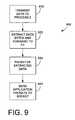
- Another aspect of the present inventioninvolves a method of sharing information with a remote computer for use in a computer operating system.
- a first step of the methodinvolves intercepting information contained within an information stream transmitted from a first local process to a second local process.
- a second step of the methoddeals with making a copy of the information.
- a third stepinvolves allowing the original information stream to reach the second local process.
- a fourth stepinvolves passing at least some of the copied information to a protocol stack process which in turn forwards the information to the remote computer via a co-socket associated with a PSTN telephone call.
- An eighth aspect of the present inventiondeals with apparatus coupled to a telephone switch.
- the apparatusemploys a translation unit which receives ANI or CLID data and translates said information relating to a caller's client internet socket address.
- the apparatusalso employs a module which places information relating to the caller's internet socket address into a data packet for transmission to a dialed telephone number.
- the internet socket addressincludes a port number to enable a callee to send a screen of information via an internet to be displayed on the caller's computer screen.
- a apparatus similaris also disclosed which evaluates dialed number information and ANI or CLID information and generates a packet sent via an internet to establish a co-socket in support of a call.
- a related method of processing telephone calls within a telephone network in support of co-socket telephonywhich may be practiced by the disclosed apparatus is also presented.
- FIG. 1is a block diagram representing a CTI server and a smart telephone connected via a point-to-point PSTN connection and an internet socket connection according to the present invention.
- FIG. 2is a flow chart illustrating a CTI server web call-back processing method according to the present invention.
- FIG. 3is an exemplary information window display used to assist a user in managing multiple telephone queues.
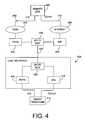
- FIG. 4is a functional block diagram illustrating a point-to-point PSTN connection/co-socket architecture using a single DSL or multiplexed telephone line.
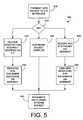
- FIG. 5is a flow chart illustrating a method of co-socket initiation utilized by a calling device according to the present invention.
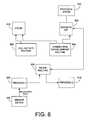
- FIG. 6is a flow chart illustrating a complementary method of processing utilized by a called device to respond to and participate in the establishment of a co-socket in accordance with the method of FIG. 5 .
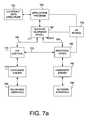
- FIG. 7is a block diagram illustrating an application programmer interface used to interface to a protocol stack having co-socket establishment capabilities.
- FIG. 7 ais a block diagram illustrating one embodiment of a software architecture for use on a smart telephone or computer according to the present invention.
- FIG. 8is a block diagram illustrating a filter program according to the present invention which is operative to intercept bytes within an information stream and transmit a copy of the intercepted bytes across a socket or co-socket.
- FIG. 9is a flow chart illustrating a method of sharing screen information with a remote computer using a filter module.
- FIG. 10is a block diagram of one embodiment of a central office switching apparatus according to the present invention, which is used to perform ANI to co-socket address database translations.
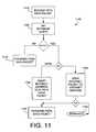
- FIG. 11is a flow chart illustrating a method of performing caller identification to co-socket address database translations.
- FIG. 12is a block diagram of an inter-exchange carrier network architecture used to perform ANI to co-socket address database translations according to the present invention.
- FIG. 13is a flow chart illustrating a method of initiating the establishment of a co-socket by a calling device using an internet database approach.
- FIG. 14is a flow chart illustrating a method of removing internet address data from PSTN data packets according to the present invention.
- FIG. 1illustrates a first embodiment of a communication configuration whereby a CTI server 100 and a smart telephone 115 are each coupled to a PSTN 105 and an internet 110 .
- a peer device 102may be another device similar to the smart telephone 115 , and is also coupled to the PSTN 105 and the internet 110 .
- An optional database system 112may also be coupled to the network configuration via the internet 110 . As will be discussed in connection with the embodiments illustrated by FIGS. 10-12 , the database 112 may also be implemented by equipment within the PSTN 105 .
- the PSTN 105may be coupled to the internet 110 via various types of connections 107 which may include a gateway connection to route long distance voice traffic across the internet 110 .
- the database moduleis an internet server.
- the database module 112includes a coupling to the internet 110 . This coupling is operative to receive a client request from the internet 110 including information relating to a telephone number associated with a potential callee.
- the database 112associates the telephone number with an internet address.
- the database 112includes a reply module connected to the coupling and is operative to return a data packet via the coupling to the internet 112 upon association of the request with the internet address.
- the data packet sent out by the database 112is related to the internet address of the callee. Once this data packet is returned to the smart telephone 115 , the smart telephone 115 may initiate a co-socket with the callee instead of, or in addition to a telephone connection.
- the CTI server 100may read CLID data associated with an incoming call and send this information to the database 112 to find out an internet address related to the caller. This allows the CTI server 100 to pop a screen of information on the caller's screen in response to an incoming call.
- the CTI server and/or the smart telephone 115may incorporate a local database to translate telephone numbers to internet socket addresses.
- the CTI server 100includes a main computer 120 which is coupled to a CTI interface 125 , an internet protocol stack 130 , a storage unit 135 , and an optional call center 140 .
- the main computer 120may be implemented with an Intel Pentium processor or a computer board such as a mother board built around an Intel Pentium processor.
- the coupling to the storage area 135may be implemented using a bus connection to a solid state memory.
- the storage area 135is implemented at least partially with a mass storage device such as a disk drive.
- the mass storage unit 135is preferably coupled via a disk controller which is itself coupled to the main computer 120 via a standard type of bus interface such a peripheral component interconnect (PCI) bus.
- PCIperipheral component interconnect
- the storage unit 135may be configured to support voice mail and other forms of multimedia message storage.
- the internet protocol stack 130is typically implemented as software process on the main computer 120 and hence is coupled via a software connection such as an interprocess communications channel.
- Application programs running on the main computer 120typically access the internet protocol stack 130 using a function call to an API such as a WinSock API or a UNIX Sockets API.
- the CTI interface 125is also usually implemented as one or more software processes which execute on the main computer 120 .
- An application program running on the main computer 120is coupled to the CTI interface 125 via an interprocess communications link provided by an operating system running on the main computer 120 .
- the couplingis provided between an application program running the main computer 120 and the CTI interface 125 via a call to a CTI API.
- an argument list to a function calltypically coupled information from the main computer 120 to the CTI interface 125 . Call queue and IVR systems are ideally maintained by applications programs which run on the computer 120 .
- the call center 140preferably consists of an automatic call distribution (ACD) system which routes incoming calls to one or more call processing agents.
- the main computer 120is typically coupled to the call center 140 using a plurality of twisted pair cables, one pair for each agent station.
- trunckingmay be employed whereby a single twisted pair carries a plurality of calls to a remote call center and multiplexing and demultiplexing equipment is used to separate and combine the multiple calls on the single twisted pair.
- Some systemsmay couple the call center 140 to the main computer 120 using LAN technology.
- LAN technology for call distributioninvolves compressing and packetizing calls for shipment over a coaxial cable.
- An optional data link 145couples the CTI interface 125 directly to the internet protocol stack 130 , which is of the type well known in the art.
- This direct data link 145allows information at lower layers (network, link and physical layers) of the protocol stack 130 to communicate with the CTI interface 125 .
- This data linkis typically embodied either as a parameter list involved in a function call or via an interprocess communication mechanism.
- Couplings between all the modules in the CTI servermay be implemented through the computer 120 .
- these couplingsmay be implemented by auxiliary data paths, direct memory access transfers, or directly by the processor using move operations.
- the input/output structure of the internet protocol stack 130preferably includes a first coupling to an application layer via an API accessed by an application program running on the computer 120 , and a link layer interface to a remote network device in the internet 110 .
- Common examples of link layer interfacesinclude modems which connect a home to an ISP, a PSTN voice telephone circuit established between two users, a CATV connection from a Web-TV client to a CATV based ISP, or a LAN connecting from a computer to a remote internet server.
- Each of the foregoing link layer interfaces(as well as other similar arrangements) may be used within the present invention.
- the smart telephone 115includes several subcomponents.
- the smart telephoneis controlled by a processor 150 which can be any logic processor including for example an ASIC, an embedded microprocessor, or computer motherboard, each of which are well known in the art.
- a processor 150which can be any logic processor including for example an ASIC, an embedded microprocessor, or computer motherboard, each of which are well known in the art.
- an Intel Pentium processormay be used in a smart telephone implemented as a personal computer.
- the Intel Pentium processoremploys on-board functional units and an on-board cache to execute a version of the so-called Intel Instruction-Set.
- the Intel Pentiuminterfaces to an external system using a data bus, an address bus, and a control bus.
- Stand-alone smart phoneswhich are not implemented as a part of a personal computer may be implemented with specialized microprocessors such as the ARM processor from Advanced RISC Machines Inc.
- the ARM processoremploys a reduced instruction set computer (RISC) architecture and may be integrated on the same chip with special purpose circuitry to form a customized type of microcontroller.
- More standard types of microcontrollerssuch as the MC68HC16 by Motorola Inc. may be also be used to implement the processor 150 of the smart telephone.
- the MC68HC16integrates a 16-bit MC68000 processor core by Motorola Inc. with a collection of peripheral devices on the same chip.
- the interface and design techniques for all of these types of processorsare well known and are documented in the microprocessor literature and the documentation available from the aforementioned companies.
- the processor 150Once programmed, the processor 150 may be viewed as being constructed of various computer modules which interact and perform their programmed functions. In an ASIC design, the processor 150 may be implemented as an interconnected combination of hardwired computer modules
- the processor 150is coupled to a CTI interface 155 and to an internet protocol stack 160 .
- the CTI interfaceis also preferably coupled to a handset 158 which may alternatively be coupled directly to the processor 150 .
- the internet protocol stack 160ideally has a structure similar to the protocol stack 130 as discussed in connection with the CTI server 100 above.
- An optional direct coupling 163may be provided between the CTI interface 155 and the protocol stack 160 .
- the processor 150is preferably also coupled to a storage unit 165 which includes memory and which may include mass storage implemented in technologies such as hard disk drives, solid state disk drives, or other means.
- the processor 150is also coupled to an input/output terminal 170 which includes a graphics display capable of displaying windows and/or dialog boxes.
- the input/output terminalalso preferably includes a keyboard and/or mouse to accept user inputs.
- the processor 150is also be advantageously coupled to a one or more sensors 175 . Examples of sensors which may be coupled to the processor include a video camera, a digital camera, a scanner or other multimedia data collection means.
- the processor 150is also coupled to a wireless link layer interface 180 .
- the wireless interface 180may involve a wireless LAN and is preferably used to couple the smart telephone 115 to a remote unit 185 .
- the remote unit 185provides mobility to the user by allowing him or her to leave the vicinity of the smart telephone but still be able to handle calls and manage program operation on the smart telephone.
- the apparatus of FIG. 1may operate in many different modes to support various methods and applications.
- a caller using the smart telephone 115wishes to call the call center 140 which is coupled via the CTI server 100 .
- the smart telephone 100is associated with the caller.
- the call center 140is reachable via a PSTN 1-800/888 number.
- a callerpreferably dials the 1-800/888 number using either a keypad associated with the handset 158 or an automatic CTI-controlled dialer which may be part of CTI interface 155 .
- the phone numberis found in a list or is entered using the I/O windows interface 170 .
- PSTN 105whichever dialing method is selected, the dialed 1-800/888 number transmitted over a telephone line to a PSTN switch located in PSTN 105 , possibly via a PBX (not shown).
- the PSTNmay interact with the dialed number or the CTI interface may add extra data to the dialed number indicative of an internet socket address.
- a PSTN data packetis defined as any data packet which routes over the PSTN. PSTN data packets are used for call set-up, communication systems management, and other purposes. PSTN data packets are most typically sent using SS7 or X.25 protocols.
- the CTI interface 125controls the line pick-up process to accept the call.
- CTI interface 125listens for a tone sequence.
- the expected tone sequencecontains a synchronize sequence numbers (SYN) segment used to set up an internet connection. SYN segments, and internet stream socket and datagram socket connection establishment procedures are well known in the prior art, and are discussed in full detail in “TCP/IP Illustrated Vol. 1-3,” by W.R.
- a segmentis generally defined in TCP as a timed packet. When a segment is transmitted, a timer starts, and when an acknowledgment is received, the timer stops. If the timer runs out, a new segment is transmitted.
- SYNThis flag is set during the exchange of segments used to establish a TCP connection.
- a TCP connectionis also called a stream socket. The SYN packet exchange sequences used to set up a TCP connection are discussed in detail in Section 18.6 of Volume 1 of the aforementioned Stevens reference. SYN segments are embodied as UDP datagrams in the TCP protocol.
- TCPis chosen as the protocol for use with the present embodiment, other protocols and formats may be used with equal success.
- a “co-socket”may be established using a session layer protocol which executes over a transport layer protocol. Standard sockets are transport layer connections. Co-sockets as defined within the scope of the present invention may be defined at any specified layer of any selected protocol stack without restriction. Hence at any point, a SYN segment may be replaced with a connection establishment packet for a given protocol.
- a “SYN segment”is generally defined as any data which may be transmitted via various methods and formats as a part of any internet connection establishment process.
- a SYN segmentmay simply constitute an internet address used to indicate an internet address and port number needed to begin a TCP/IP SYN segment exchange sequence.
- a point-to-point telephone connectionis generally defined as any dialed telephone connection set up between two or more telephones.
- a point-to-point PSTN telephone callis defined as any telephone connection between users set up using a PSTN or PBX originating or terminating line. This connection may be established via a PBX between phones within an enterprise, and may also route partially across an internet.
- the point-to-point PSTN telephone callis not established as a PC-to-PC multimedia packetized telephone call using a format such as H.323. Such telephone calls already have full multimedia capabilities.
- the CTI interface 125answers the phone in response to a ring-signal and listens for a tone sequence. If the caller is using a smart telephone such as the smart telephone 115 , the smart telephone 115 is the requesting end of the connection so transmits a SYN packet over the established point-to-point telephone connection. If the phone goes unanswered, but CLID or related information is accepted by the called number, then a point-to-point connection is still established in response to the call, but the point-to-point connection may be termed a PSTN-datagram connection instead of a voice circuit.
- the CTI interfacereceives and decodes a sequence of tones indicative of a SYN segment.
- the SYN packetis transmitted from CTI interface 155 to CTI interface 125 and is used to set up a TCP/IP stream socket connection across the Internet.
- internet 110corresponds to the Internet.
- FIG. 1Several methods may be used by the apparatus of FIG. 1 to establish an internet connection using a point-to-point telephone connection which has been established via the PSTN 105 . These methods are discussed in greater detail below in connection with FIGS. 5-7 and FIG. 11 .
- an entire TCP/IP stream socket connection establishment SYN sequenceis exchanged between smart telephone 115 and the CTI server 100 using the CTI interface 155 and the CTI interface 125 .
- the CTI interface 125is coupled to the protocol stack 130 via the computer 120 or the optional direct coupling 145 .
- the CTI interface 155is coupled to the protocol stack 160 via the processor 150 or the optional direct coupling 163 .
- a TCP/IP stream socketis established via the CTI interfaces 125 and 155 .
- the connectionis then passed across to the protocol stacks 130 , 160 to enable internet data communication.
- the direct couplings 145 and 163are provided to allow the protocol stack processes 130 , 160 to directly interact using the CTI interfaces 125 , 155 which communicate using the point-to-point telephone connection established across the PSTN 105 as a link layer.
- the protocol stackmay then switch its link layer interface from the point-to-point PSTN link to a link coupled to the internet 110 .
- Note a stream socket established in this manneris a co-socket as defined hereinabove.
- the above described methodmay be used to establish an internet co-socket.
- the above exampleillustrates one variation whereby the entire co-socket connection establishment sequence is carried out using the point to-point PSTN connection to supply the link layer interface. Subsequently, the link layer of the co-socket is switched a link layer interfaces coupled from the protocol stacks 120 , 160 to the internet 110 .
- Another embodimentrequires that only a first SYN segment be transmitted over the point-to-point telephone link with all subsequent SYN segments being transmitted on the link coupled to the internet 110 .
- Still other embodimentsutilize an initial SYN segment which is encoded into a CLID packet and transmitted via a PSTN data packet such as an SS7 packet.
- the CLID information of the callermay be replaced by SYN data using a variety of methods as discussed herein in connection with FIGS. 5-7 and FIG. 11 .
- a call processing method 200 employed by the CTI server 100 when called by a smart telephone client 115 via a point-to-point PSTN connectionis disclosed.
- a calleris required to navigate a set of menus and wait in a queue to speak to an agent residing in the call center 140 .
- the CTI serverreceives a SYN segment over the PSTN.
- This SYN segmentmay be transmitted using a CLID-like packet sent via SS7 before the server 100 answers the call, or the data packet may be transmitted over the point-to-point PSTN connection using a tone sequence once it is answered by the CTI server 100 .
- the SYN segmentmay be transmitted by having the caller key in touch tones, press an automatic dialer button, or speak an internet address which is then converted using voice-to-text translation within the CTI server 100 . It can be appreciated that a broad variety of different combinations may be used in such applications without departing from the spirit of the invention.
- an internet connectionis established in a second step 210 .
- the internet connectionis a TCP/IP stream socket set up using the co-socket techniques of the present invention. More details of how this step may be performed are provided in connection with FIGS. 5-7 and FIG. 11 .
- controlpasses to a third step 215 .
- the callmay be preferably dropped or rejected. This step 215 is optional and may be initiated, for example, only after receiving a caller consent input.
- the callneed never be answered, but may be rejected outright in the third step 215 .
- controlis passed to a fourth step 220 which transmits a dialog form to the caller via an internet.
- the reason the call may be dropped or rejectedis that the caller may use a dialog box such as the dialog box 300 (see discussion of FIG. 3 below) displayed on the computer screen 170 instead of the IVR voice prompts presented by the CTI server 100 .
- the callis preferably rejected because the caller will use the internet call queue discussed below and the more expensive and less friendly telephone connection is not presently needed.
- the dialog box 300is maintained over the internet, ideally using a web browser.
- the dialog boxmay appear directly in a web browser window, or alternatively may be displayed in a separate window using, for example, a CGI script, a browser plug-in, or a Java applet.
- CGI scripts, browser plug-ins, and Java appletsare well known in the computer arts and are discussed in detail, for example, in “Netscape Technologies Developers Guide” by L. Duncan and S. Michaels, Ventana Publishing, 1997, and “Web Developer's Secrets,” by Harold Davis, IDS Books Worldwide, 1997, both of which are incorporated by reference in their entirety herein.
- any application layer programmay be used to accept and display the aforementioned dialog box.
- controlpasses to an optional fifth step 225 which accepts a remote caller's inputs across the internet, preferably by accessing a sockets API.
- a decision 230is made to determine if more input is needed, in which case control is passed back to the fourth step 220 .
- the fourth step 220transmits another dialog box and passes control to the fifth step 225 which waits for more user input.
- controlis passed to a sixth step 235 which transmits one or more queue timer values to the remote caller via the internet.
- the timercan be continually decremented and redisplayed in a count-down fashion on the display to the remote caller's terminal. If the CTI server 100 wishes to modify the estimated caller queue wait time, it sends out an updated time which will divert the decrementing counter from its path by reinitializing it to a new estimate.
- the sixth step 235proceeds until either the timer runs out or additional wait time is requested by the remote caller. If additional time is requested, a decision 250 is made to accept the additional time and to pass control back to the sixth step 235 to add this time to the timer.
- the decision 250also allows the user to freeze a timer which in effect, adds more time to the queue-wait.
- the PSTN phone numbermay be obtained by the CTI server 100 from a CLID packet, a CGI script, a Java applet, user input to a dialog box, a database, or other well known technique.
- the aforementioned method 200is especially useful because it allows a caller to manage multiple tasks in parallel.
- a callerwishes to make three phone calls at once, each of which involve non-trivial telephone queue waiting times.
- the callerinitiates the calls from the smart telephone 115 .
- the callercalls a first CTI server and establishes an internet dialog session as discussed in connection with the method 200 above.
- the userreceives an estimated queue time according to the sixth step 235 . This time is displayed in a first timer window. Assume for example that the queue wait is ten minutes.
- the callerdecides to make a second phone call while the first timer is running.
- a timer-manager windowallows a user to conveniently view multiple queue-wait times and increment times in various increments using point-and-click technology as discussed in connection with FIG. 3 herein. The user may click on various buttons to freeze remote queue-timers or add time. Further assume that by the time the user receives the six minute time for the third call-queue, the first call queue is reduced to five minutes.
- the callermay freeze the timer at the eighteen minute mark until the urgent matter or second call is completed.
- a freeze buttonsuch as the freeze button 315 of FIG. 3 below may be actuated whereby the timer is again allowed to proceed.
- the callerhas allowed others in the queue to progress ahead without having to reinitiate the call and start at the beginning of the queue again.
- the CTI server associated with the call centerhas not accrued telephone toll charges during the “freeze” period. The ability for the user to interact with the amount of time left in the call queue represents an improvement over prior art web call-back systems as previously described.
- the wireless interface 180is used to transmit timer status information (and optionally a voice connection) to a user who is remote to the smart telephone 115 .
- timer status informationand optionally a voice connection
- the callerthen directs the system to forward all the timer data and a voice circuit to the remote unit 185 .
- the remote unit 185By carrying the remote unit 185 , the caller can be at a different location from the smart telephone and perform many or all of the functions discussed above using the smart telephone 115 via the remote unit 185 .
- the web call-back system as described abovemay be initiated by either PSTN calls or, for example, H.323 packet calls.
- the first step 205 of the method 200involves receiving SYN packets over an internet instead of the PSTN.
- the benefits of allowing the caller to freeze queue timers or add time to call queuesmay thus provided to web callers as well.
- FIG. 3A first embodiment of a user interface menu 300 displayed by a smart phone according to the present invention is illustrated in FIG. 3 .
- the user interface menu 300may be displayed by an application program to include a web browser's main window, a plug-in, a CGI script, an applet, or any program from within an operating system.
- a timer window 305may preferably display the remaining wait-queue time for each active wait-queue.
- An add button 310is used to cause time to be added to the associated time as displayed by timer 305 .
- a freeze button 315is used to cause the associated timer 305 to freeze, as previously described.
- a count button 320is used to cause the associated timer 305 to resume counting.
- buttonsWhen these buttons are selected, packets are transmitted to the remote CTI server 100 and are acted thereupon in the eighth step 250 of method 200 as shown in FIG. 2 . Additional inputs and buttons may be made available to add times and perform other interactions with the wait queues using extra dialog windows or icons as illustrated by the graphics object 325 .
- a graphics object 325may support control commands to forward data and calls to the remote unit 185 .
- the smart telephone 115supports other inventive uses for CTI initiated co-sockets. These uses are discussed below in connection with FIGS. 8 and 9 . Note also that the smart telephone 115 may also be used to perform internet database dialing as discussed in connection with FIG. 13 .
- a line interface techniqueis illustrated for connecting the smart telephone 115 to support a point-to-point telephone connection and an internet link layer interfaces using a single telephone line as a physical layer interface.
- the smart telephone 115is coupled to a line interface 400 which preferably includes a digital subscriber line (DSL) modem of the type well known in the art.
- DSLdigital subscriber line
- the DSL modemis operative to convert a high speed data stream, for example on the order of up to 6 Mb/s into an out-of-band carrier signal used to transmit data across a phone line.
- POTSplain old telephone service
- the POTS interfacemay be substituted for a digital interface such as an ISDN line.
- voice trafficmay be multiplexed directly into the DSL data signal.
- a splitter 420is used to separate the POTS voice circuit from the out-of-band DSL data.
- a splitterless DSL modem technologymay be used. The basic concept behind the splitter 420 is to provide a means to separate the voice channel from the data stream transmitted over the DSL channel. If the voice data is packetized and multiplexed onto the DSL data signal, then the splitter 420 may be viewed as the multiplexer which performs this function. In this case the splitter block 420 should be physically located to the other side of the DSL modem 415 and the POTS interface 405 so as to be connected between these devices and the smart telephone 115 .
- the splitter 420provides a coupling to a telephone line 425 .
- the telephone line 425couples via local wiring or wireless means to a second splitter 430 .
- the splitter 430separates the PSTN voice circuit from the DSL circuit and forwards the PSTN voice frequency signal to the PSTN while forwarding the DSL signal to a DSL interface.
- the splitter/multiplexer 430decode the DSL signal and sends a bit stream to an internet service provider (ISP) 440 over a digital link.
- ISPinternet service provider
- the digital datais forwarded from the ISP 440 via an internet 465 to a link layer interface 470 which carries typically a TCP/IP packet stream to a remote site 460 .
- a link layer interface 470which carries typically a TCP/IP packet stream to a remote site 460 .
- the splitter/multiplexer 430will separate the voice data and forward it to a PSTN (or local) voice circuit.
- a PSTN interface 435is used to process the voice circuit and to couple it to the PSTN 445 .
- the PSTN 445is used to couple the voice circuit to the remote site 460 over a line telephone 450 , preferably controlled by a CTI interface.
- FIG. 4The operation of the apparatus of FIG. 4 is essentially the same as that discussed in connection with FIGS. 1-3 above. Details of the CTI based co-socket connection techniques are discussed in connection with FIGS. 5-6 and FIG. 11 herein.
- a telephone connectionis a link layer interface which connects a caller to a callee.
- This functionalitycan in fact be implemented in separate links using a single telephone line as a physical layer interface. Additional but related embodiments involve a second telephone line, a separate LAN connection, a Web-TV internet access point or an enterprise WAN connection, for example.
- DSLis a special case of the smart telephone configuration wherein two separate links are effectively provided by a single telephone line used as a shared physical layer interface between two link layer interfaces.
- a method 500is illustrated to establish an internet co-socket with a remote station via a separate point-to-point telephone connection.
- This methodenables, inter alia, multimedia phone calls which route voice traffic over the PSTN, and also route data traffic over the Internet.
- the method 500is practiced by the smart telephone 115 of FIG. 1 which represents the calling or requesting end of a connection, although other configurations can be used.
- the method 500may be practiced by any telephone device which initiates a multimedia co-socket connection.
- the method 500starts when the smart phone 115 has already dialed a phone number corresponding, for example, to the distant end CTI server 100 or the peer smart phone 102 of FIG.
- a SYN segmentis sent to the distant end using a CLID packet, touch tones, speech, or other available means.
- a CLID packetIn campus or similar environments, a fixed or dynamic table mapping ANI data to socket addresses may be used.
- a “dumb” telephonei.e., a standard telephone without processing capabilities
- an enterprise computercan be used to map the dialed number and ANI data into a SYN segment containing the information needed to initiate a session to establish a co-socket between the computers belonging to the caller and the callee.
- the first step 505involves transmitting at least enough information to notify the distant end and prompt it to establish a co-socket.
- controlpasses to an options decision point 510 .
- the options decision point 510may represent a selection operation or may represent a hard-wired transfer of control to, for example, either a second step 520 , a fifth step 550 , or a sixth step 560 .
- the second step 520receives an acknowledgment packet over the CTI interface 155 .
- the received packetpreferably contains an internet address. With this internet address available, control passes from the step 520 to the third step 530 which passes the received internet address to a protocol stack which in turn establishes an internet connection with the remote CTI server 100 or the remote peer 102 .
- the internet connectionis a TCP/IP stream socket established across the Internet, although other configurations are possible.
- controlthen passes to a fourth step 540 which uses the internet connection to pass data, preferably between application processes residing on the smart telephone 115 and the remote CTI server 100 , or the peer 102 .
- the established internet connectionis a co-socket to the point-to-point PSTN telephone connection used to receive the server's internet address. Note that if control transfers from the first step 505 to the second step 520 , the first step 505 only must transmit enough information to prompt the distant end to send an internet address. It is contemplated by the present invention that in such a situation, the first step 505 could be eliminated altogether by having the distant end transmit an internet address to all callers, thereby simplifying call processing.
- an entire SYN sequenceis exchanged using a point-to-point PSTN connection between the smart telephone 115 and either the remote server 100 or the peer 102 .
- This SYN sequenceis used to establish an internet connection.
- This internet connectionis a co-socket.
- controlis transferred to the fourth step 540 which uses a separate link layer interface to connect to the internet.
- This separate link layer interfaceis connected to an internet and is also called a “network interface.” The separate link layer interface connected to an internet is different from the telephone connection.
- the point-to-point telephone connectionmay continue to be used or may be dropped if desired and communication may take place only over an internet.
- peer-to-peer communicationsfor example, it may be desirable for users to converse over the PSTN link and to exchange multimedia data over the co-socket.
- at least one SYN acknowledge packet(which is typically the first part of a connection establishment sequence) is received over the CTI interface 155 . If the path involving the sixth step 560 is selected, the first step 505 will preferably send the first SYN segment in the internet socket establishment sequence.
- control passes to the fourth step 540which allows application processes residing in the smart telephone 115 and the remote CTI server 100 or peer 102 to exchange information.
- a method 600is illustrated for establishing an internet co-socket at a remote station via a separate point-to-point PSTN connection.
- This methodis practiced by a receiving (i.e., callee) side of a connection such as the CTI server 100 .
- this method 600interacts with the previously described method 500 ( FIG. 5 ) to enable multimedia phone calls which route voice traffic over the PSTN and data traffic over an internet.
- the method 600is practiced by the CTI sever 100 or the peer 102 upon receipt of a connection request from smart telephone 115 .
- a first step 605is carried out to receive the SYN segment sent from the first step 505 of the method 500 as placed by the smart telephone 115 .
- a SYN segmentis received from the distant end via a CLID packet, touch tones, speech, or other suitable transmission format.
- controlpasses to an options decision point 610 .
- the options decision point 610may represent a selection operation or may represent a hard-wired transfer of control to, for example, to either the a second step 620 , a fifth step 650 , or a sixth step 660 .
- the second step 620responds to an internet address query received in the first step 605 and transmits an acknowledgment which is preferably an internet address over the CTI interface 125 .
- controlpasses from the second step 620 to the third step 630 which represents a listening server side internet connection preferably corresponding to the transmitted internet address.
- the third step 630is used to perform the server side protocol of a client-server connection establishment exchange with the remote client who received the appropriate internet via the CTI interface.
- the smart telephone 115calls the CTI server 100 or the peer 102 of FIG. 1 and establishes a co-socket.
- controlpasses to a fourth step 640 which uses the internet connection to pass data, preferably between application processes residing on the CTI server 100 and smart telephone 115 . If this method is practiced by a peer device 102 , then a peer-to-peer connection establishment protocol may be employed similarly to a client-server protocol, or the peer may act as a server in the connection.
- an entire SYN sequenceis exchanged using a point-to-point PSTN connection between the called CTI device and the calling smart telephone 115 .
- This SYN sequenceis used to establish an internet connection.
- This internet connectionmay be termed a co-socket connection because it requires a PSTN (or PBX) co-channel to establish it.
- controlis transferred to the fourth step 640 which uses a separate link which connects to the internet.
- the point-to-point connectionmay continue to be used or may be dropped and communication may take place over the internet connection.
- peer-to-peer communicationsit may be desirable for two or more parties to converse over the PSTN link and to exchange images and other forms of data over the established co-socket connection.
- the sixth step 660at least one SYN acknowledge packet which is part of a connection establishment sequence is transmitted over the CTI interface 125 . If the sixth step 660 is selected, the first step 605 will preferably receive at least one SYN segment in an internet socket establishment sequence. Once at least SYN acknowledgment packet is sent in the sixth step 660 over the internet, control passes to a seventh step 665 which continues to exchange SYN segments over a separate link connected to the internet 110 . Once the internet co-socket connection is established, control passes to the fourth step 640 which allows application processes residing in the called computer to exchange information with the application processes in the calling computer. For example, the called CTI server 100 or peer 102 may exchange information with the calling smart telephone 115 .
- the method 600also contemplates an alternative co-socket establishment procedure.
- the data packet received in first step 605is preferably a CLID data packet.
- the CLID data packetmay comprise a caller's name and telephone number as is common in the art.
- the received informationmay comprise a modified CLID packet which includes a caller's internet socket address suitable for popping a screen of information on the caller's computer screen. Apparatus to provide such an internet socket address in a CLID data packet is discussed in connection with FIGS. 10-13 . If the CLID data packet does not include an internet socket address, then the first step 605 is operative to perform a database translation to convert the CLID information to a caller's internet socket address.
- the database used to perform this translationmay be local or remote. That is, the step 605 may involve performing a database query to a remote database accessible through the internet. A remote database which may be used for this purpose is shown as the database 112 in FIG. 1 .
- controlnext passes from the first step 605 directly to the step 665 , bypassing the optional step 660 .
- an internet socketis established from a computer practicing the method 600 back to a computer controlled by the caller.
- the step 665is preferably performed over a link layer interface other than the telephone connection on which the CLID data packet Was received.
- This alternative procedurehas the advantage that a caller can call from a standard telephone and still receive a screen of information from the callee.
- a callercan call from a standard office telephone and receive a screen of information from the callee.
- a callercan initiate a call from a standard telephone in a home and receive a screen of information on a computer connected to a second line, a CATV terminal, or a Web-TV internet appliance connected to a television set.
- the method 500 and the methods 200 , 500 , and 600may all be advantageously implemented via a computer program which executes on a processor coupled to a memory.
- a computer programis defined herein generally as a sequence of instructions which executes on a processor. Typically the computer program is stored in a semiconductor memory, and instructions are read by a processor from the memory in sequence. The processor typically executes the instructions sequentially in the order in which they are read from memory. In modem processors with out-of-order execution, slight variations from strict sequential orderings are allowed to provide speed advantages.
- a computer programis represented at its lowest level in machine language.
- Machine languageis a representation of instructions as operation codes (opcodes) which are embodied as binary words consisting of zeros and ones. Programs are more conveniently written in a high level programming language such as C and Pascal are even easier. High level programming languages are well known in the art and are used to construct high level instruction sequences wherein each high level instruction may be translated into a collection of machine language instructions.
- opcodesoperation codes
- C and Pascalhigh level programming languages
- Most computer systemssupply an operating system as an interface between a user's program and a computer's hardware resources.
- Well known operating systemsinclude UNIX as originated from AT&T Bell Labs, and Windows95 and Windows NT as produced by Microsoft Inc.
- An operating systemis a computer program which provides driver programs and programs which load and execute other programs. Modern operating systems also typically provide mechanisms to allow different programs to communicate with each other.
- APIapplication programmer's interfaces
- An APIis accessed by an application through a so-called “function call.”
- a functionis a software routine which performs some specified action.
- a function callis a set of one or more instructions which sends a set of parameters to the function and invokes the function. For example, if a program is written in C and runs on a personal computer running Windows95 , an API may provide a function to allow an application program to access a protocol stack coupled to an internet.
- a telephony APImay also be supplied to allow an application program to interact with a telephone interface.
- telephony API function to pick up a telephone line or to digitize a signal received on a telephone linemay be supplied as a function associated with a given API.
- Operating systemsoften provide API's as a library functions.
- An example of an API implemented as a library of functionsis the WinSock API which supports Windows95 and related Windows based operating systems.
- the WinSock APIprovides roughly fifty function calls, and hence the WinSock system includes a library of fifty functions. It is important to note a given application program may be written to include a call to an API.
- an operating systemmay be developed which provides an API as a part of its environment so applications which call the API may execute properly.
- an application programmer's interface (API) function 700is illustrated.
- This functionmay be included as a part of an operating system and may serve as a gateway between an application process and an operating system process which implements a protocol stack.
- the inventive APIincludes two essential inputs.
- a first input 710receives information relating to the establishment of an internet socket address, while a second input 720 receives information relating to a PSTN telephone number and/or other CTI related information used for signaling on a CTI link provided by a point-to-point PSTN connection.
- the APIprovides access to a protocol stack which may transmit and/or receive data on two separate link layer interfaces.
- a point-to-point telephone oriented link layer 730is coupled to a telephone line.
- An internet layer link interface 740is coupled via the accessed protocol stack to the internet 110 .
- the inventive APImay be used to provide an interface between an application layer process and a protocol stack in devices such as the smart telephone 115 , the CTI server 100 , or various versions of the peer devices 102 .
- the API 700 of FIG. 7may be used as a means to program the caller side method 500 or the callee side method 600 previously described.
- the API 700is operative to accept both CTI call establishment information as well as internet socket establishment information.
- This socket establishment aspect of the API 700provides a functionality associated with a network interface API.
- a network interface APIprovides an interface between an application program process and a protocol stack process which is coupled to an internet. Common network interface APIs include the Sockets API and the WinSock API.
- the API 700enables an application or operating system program to interact with a CTI enabled protocol stack used to both set up a point-to-point telephone call and an associated co-socket connection. Utilizing the methods 500 , 600 previously described (and variations thereof), the API 700 is operative to transmit internet co-socket establishment data over the point-to-point telephone link layer interface 730 , and to perform subsequent co-socket communications over the internet link layer interface 740 .
- FIG. 7 aa preferred embodiment of a software architecture to be run on a central processing unit (CPU) in a smart telephone or CTI server is presented.
- An operating system kernel 755controls various processes which share time on the CPU.
- the operating system kernel 755is coupled to an application program 750 , a sockets-telephony API 760 , and a protocol stack 785 .
- the coupling between the operating system kernel 755 and the application program 750is implemented as a task control block data structure.
- the task control block data structureis a data which holds task (i.e. process) related information.
- Task control block data structuresare maintained for one or more resident processes and are manipulated by the operating system kernel 755 .
- a processis an instance of a computer program represented by an execution flow.
- a set of process related variablessuch as a machine state relating to the process are stored in a task control block.
- the operating system kernel 755performs task switching by moving the process from a dormant state where it is stored in the task control block to an active state where it is allowed to run on the CPU.
- the coupling between the operating system kernel 755 and the protocol stack 785is implemented using a second task control block.
- the protocol stackmay itself be implemented as one or more processes, each of which are coupled to the operating system 755 via their own task control blocks.
- the operating system kernel 755is coupled to the sockets-telephony API 760 by virtue of the fact that the sockets telephony API supplies an interprocess communications function which interacts with kernel level data structures and related communication mechanisms.
- the protocol stack 785may be implemented as a part of an operating system associated with the operating system kernel 755 .
- the application program 750is coupled to a co-socket data structure 752 .
- the application programis said to “own” the co-socket 752 when the program makes a function call to create the co-socket.
- a process which owns the co-socketis able to use the co-socket to communicate with a process on a remote computer.
- a remote computermay comprise a smart telephone as described hereinabove.
- the co-socket data structureis embodied within a memory as a collection of information bits.
- the co-socket data structureincludes a standard socket data structure with the possible addition of extra fields for telephone connection related parameters as discussed below.
- the application program 750is also coupled to the sockets-telephony API 760 .
- This couplingis implemented within the application program 750 as a function call to a sockets-telephony API function.
- the couplingis implemented via a function call which references a function stored in a runtime library.
- a runtime libraryis a collection of functions which may be accessed at runtime.
- the sockets telephony API 760is coupled to a CTI control module 770 via a coupling 765 which carries telephone connection related information such as connection commands and digitized telephone signals.
- the CTI control module 770is coupled to a first hardware driver routine 775 .
- the first hardware driver routine 775is coupled to a telephone interface 780 .
- the sockets telephony API 760is also coupled to a protocol stack 785 via a coupling 767 which carries network connection related information such as socket addresses and internet data.
- the protocol stack 785is coupled to a second hardware driver routine 790 .
- the second hardware driver routine 790is coupled to a network interface 795 .
- a coupling 772may be implemented to allow the protocol stack 785 to communicate with the CTI control module 770 . This is preferably implemented in the form of a function call or via an interprocess communications mechanism supplied by the operating system.
- the coupling 765becomes optional since the sockets-telephony API 760 may pass both socket related and telephone connection related parameters to a transport layer of the protocol stack, and the transport layer can couple link level information to both the telephone interface 780 and the network interface 795 .
- the telephone interface 780 and the network interface 795represent link layer interfaces.
- a link layer interfaceis defined as a physical layer interface which carries signals, plus a signaling format such as a framing protocol.
- the physical layer interfaces of the telephone interface 780 and the network interface 795are different.
- the two link layer interfaces 780 and 795may be carried on the same physical connection.
- the telephone interface 780is coupled directly to a remote computer via a point-to-point telephone connection
- the network interface 795is coupled to the remote computer via an indirect connection through an internet.
- the sockets-telephony API function module 760itself includes structural features.
- the module 760includes a first software sub-module which is coupled to the CTI control interface 770 which is itself operably connected to the telephone interface 780 .
- the module 760also includes a second software sub-module coupled to the first software sub-module.
- the second software sub-moduleis coupled to the co-socket data structure 752 .
- this couplingis implemented by having the application program 750 pass a pointer to the sockets-telephony function 760 .
- the module 760may optionally also include a connection to the protocol stack 785 .
- the operating systemUpon application of power to the system, the operating system is loaded into memory at boot-time from a disk. In alternative embedded embodiments, the operating system may be resident in a semiconductor memory such as ROM when power is turned off, in which case the operating system is not loaded from disk.
- controlpasses to the operating system kernel 755 .
- the operating system kernelloads various processes to run such as the application program 750 and the protocol stack 785 .
- the application program 750makes function calls to the sockets-telephony API 760 in order to establish a communication socket with a remote computer.
- a function called “socket”is called to create a socket data structure.
- the socket functionreturns a pointer to the created socket data structure.
- a socket data structureis an endpoint for communication and provides a means to allow the application 760 to send and receive messages with a remote computer.
- An alternative function called “co-socket”may be used create and return a pointer to the co-socket 752 .
- the co-socket 752contains the same information as a socket data structure plus information relating to a telephone connection.
- a process which makes a function call to the co-socket functionis said to “own” the co-socket.
- the function owning the co-socketis able to use the co-socket for as a data structure in support of network communication. Further details describing the use of the co-socket data structure 752 are discussed immediately below.
- a connect functionis a software function which accepts as an argument a pointer to a socket data structure, an address of a remote socket, and a length of the remote socket address.
- a new type of connect functioncalled a “co-socket connect” function is supplied which takes an additional argument of a telephone number.
- the co-socket connect functionaccording to the present invention only requires a pointer to a socket data structure and a telephone number of the remote computer to be sent as input parameters.
- the co-socket connect functiononly requires a pointer to the co-socket data structure 752 as an input parameter.
- the co-socket data structure 752then contains the same information as a standard socket data structure plus a field relating to a telephone connection.
- the fieldmay contain a telephone number to be dialed to establish a connection with a remote smart telephone or CTI server.
- the co-socket connect functionis operative to direct a data segment to be sent to the remote computer by dialing the telephone number of the remote computer and sending a data segment to the remote computer via the dialed telephone connection.
- the data segmentis a SYN segment used in the establishment of a TCP/IP stream socket in accordance with the method 600 .
- a SYN segmentis routed over the telephone interface 780 via a point-to-point connection to the remote computer, and a TCP/IP co-socket is established to support the call using the network interface 795 .
- the sockets-telephony API 760need only be aware of the remote computer's telephone number in order to establish an internet co-socket connection with the remote computer. In practice, this sequence of events may be initiated when a caller using the smart telephone 115 dials a phone number which is answered by the CTI server 100 .
- the application program 750is configured to receive incoming phone calls.
- a CTI server application programmay be designed which receives incoming telephone calls from clients and sets up co-sockets in response thereto.
- the application program 750calls a socket function to establish a socket data structure or the co-socket data structure 752 .
- the co-socket data structure 752differs from a standard socket data structure in that it holds additional information relating to a telephone connection.
- the co-socket 752be a communication end point for a co-socket established at least partially over a point-to-point telephone connection.
- the application program 750calls a co-socket listen function.
- the sockets-telephony API 760includes a co-socket listen function which listens for incoming telephone calls carrying co-socket establishment segments.
- the listen functionis triggered into an active state.
- the listen functioncauses the CTI control module 770 to process an incoming signal to determine whether a SYN data segment has been received. If a SYN data segment has been received, the CTI control module 770 passes the SYN segment to the protocol stack 785 via the coupling 772 .
- the protocol stack 780thus uses the telephone connection as a second link layer interface over which to receive incoming SYN segments. While it is anticipated that other types information may advantageously be passed over the telephone connection to the protocol stack, the transmission of SYN segments is viewed as the preferred use.
- the listen functionis operative to receive incoming phone calls and to set up co-sockets across an internet in response thereto, just as a conventional listen function does using only the network interface 795 .
- similar structures using session layer interfacesare also within the scope of the invention. These embodiments may use session layer packets different from SYN segments and session-layer versions of a co-socket data structure.
- the software architecture of FIG. 7 aillustrates an aspect of the present invention relating to the protocol stack 785 .
- the protocol stack 785includes the coupling 772 to the telephone connection oriented link layer interface 780 and a coupling to the network connection oriented link layer interface 795 .
- the protocol stackmay be passed a first input relating to a socket data structure and a second input relating to a telephone connection.
- the second inputpreferably includes the telephone number of the remote computer to which the protocol stack is directed to connect.
- the first and second inputsmay be embodied within in the co-socket data structure 752 .
- the protocol stack 785receives a pointer to the co-socket 752 as an input parameter.
- the co-socket 752contains the first and second inputs.
- the protocol stackcauses the telephone number to be dialed, and then transmits a SYN segment over the established point-to-point telephone connection.
- the method 600is preferably employed by the protocol stack to establish a co-socket connection with the remote computer.
- the telephone numbermay be directed to be dialed using the coupling 765 , in which case the co-socket data structure 752 need only contain a telephone connection identifier.
- the protocol stackthus transmits the SYN segment over the designated connection 780 and preferably implements the method 600 . Once the co-socket is established, subsequent internet communication occurs over the network connection 795 .
- the second inputpreferably includes a telephone line identifier for one or more telephone lines over which telephone calls requiring co-socket services may be received.
- the co-socket listen functionis passed a pointer to the co-socket 752 which includes a socket data structure plus a telephone line identifier.
- the CTI control module 770signals the event to the protocol stack 785 via the coupling 772 .
- the protocol stack 785is operative set up a co-socket for subsequent communication over the network connection 795 . This connection is set up in response to the SYN segment received on the telephone interface 790 .
- the protocol stack 785preferably implements the method 500 to establish the co-socket connection with the remote computer in response to the incoming call. If the coupling 765 is used, the application program may be involved in routing the received SYN segment back to the protocol stack via the coupling 767 .
- FIG. 8illustrates a filter program according to the present invention which enables users to, inter alia, share images and other forms of computer data over a co-socket internet connection while conversing over a PSTN telephone connection.
- a filter routine 800is coupled via software connections to a first process 805 and a second process 810 .
- the filter programis also coupled to a sockets API 820 which provides access to a protocol stack 822 .
- the process 805may receive input from various sources to include a sensor device 815 .
- the sensor devicemay include a digital camera, a keyboard, a mouse, and/or any other devices which may be connected to receive input.
- Resident in the same computeris a “call initiate” routine 825 which is coupled to a CTI API 830 .
- the CTI API 830may optionally receive an input from a connection establishment routine 840 .
- the connection establishment routine 840is coupled to provide input and make calls to the CTI API 830 and the sockets API 820 .
- the inventive filteris operative to intercept at least a portion of a data stream sent from the first process 805 to the second process 810 and to route the intercepted data across a co-socket maintained by the protocol stack 822 .
- the filter 800may be coupled directly to the protocol stack 822 without using an API, but an API represents a preferable approach.
- the first process 805is a word processing program.
- the second process 810is a windows process which receives data from the first process and displays the received data in a window on a local computer display screen.
- the filter routine 800copies this data stream and preferably formats it into an application layer packet stream suitable for transmission to an application layer program which resides on a remote computer coupled to an internet co-socket connection as managed by the protocol stack 822 .
- the co-socketis established using the method 500 or the method 600 .
- the CTI API 830 and the sockets API 820may also be merged using functions similar to the function 700 .
- the preferred use of the filter 800is to allow remote users to converse on a communications device (such as a telephone) while sharing computer data via an internet co-socket.
- a communications devicesuch as a telephone
- remote colleaguesmay be discussing a document over the telephone.
- the filter programintercepts and copies the data stream sent from a word processor to a windows display process, the copied data stream will contain display information needed to display the word processor data on the remote computer's screen.
- the filtersends this data across the co-socket to the remote site so the colleague on the remote end of the phone line may view and discuss the same word processor display window.
- this type of data and media sharingis known as data conferencing.
- the filter 700enables a mixed mode of data conferencing whereby preferably voice is carried over a toll quality PSTN circuit and other forms of media and data are transported across an internet via a co-socket.
- FIG. 9illustrates a method of processing 900 carried out within a computer or smart phone.
- a first processtransmits a data stream to a second process.
- the data streammay be transmitted from a first thread to a second thread, from a first module to a second module, or most generally from the domain of a first set of instructions to the domain of a second set of instructions.
- a “thread”is an execution flow which may exist independently from others.
- a processmay have one or more threads of execution.
- a second step 920is preferably implemented using a third process separate from the first and second processes. This third process is a preferably a filter process interposed between the first process and the second process.
- Control in the filter processnext passes to a third step 930 which packetizes the intercepted information stream.
- the packetized datais preferably packetized into an application layer packet stream formatted for use by an application program residing on a remote computer (which is coupled via a co-socket).
- Controlnext passes to a fourth step 940 which sends the packetized data stream to the co-socket.
- This methodenables real-time data conferencing to occur by sending voice data over a PSTN voice circuit and image or other forms of computer data across an internet co-socket.
- FIG. 10illustrates an exemplary central office switching arrangement 1000 in accordance with the present invention.
- a subscriber line interface circuit moduleis preferably coupled to fiber and cables carrying large numbers of twisted pairs which provide subscribers with local loop access to the PSTN.
- the signals carried on this wiringare typically digitized and multiplexed and coupled to a digital central office (DCO) 1020 .
- the digital central office 1020includes a stored program computer (SPC) module 1030 which executes a switch generic program providing digital control, network management, and other services.
- the SPC module 1030is coupled to an automatic number identification/automatic socket identification (ANI/ASI) data base and translation module 1040 .
- ANI/ASI database and translation module 1040may be a part of the DCO and coupled to mass storage devices (not shown).
- the ANI/ASI database and translation modulemay optionally be coupled to a TCP/IP protocol stack 1050 , preferably via a sockets API (not shown).
- the DCOpreferably includes a main communication data path and a signaling path which couples to a switching fabric 1060 .
- the switching fabric 1060couples to an interoffice trunk interface module 1070 which couples long distance traffic out of the local access transport area (LATA).
- LATAlocal access transport area
- the central office switching arrangement 1000 of FIG. 10is operative to switch intra-LATA traffic as well as inter-LATA traffic as is well known in the art.
- the central office switching arrangementpreferably uses a standard SPC DCO architecture which is operative to perform time division multiplexing of subscriber channels and to provide services such as ANI/CLID, automatic message accounting, and maintenance and control functions.
- the switching fabric 1060may be implemented using any one of a number of well understood switching fabric architectures such as space-time-space, time-space-time, or shared memory ATM-packet, for example. Since central office switching is a mature technology and well known to those of ordinary skill in the telephonic arts, these aspects will not be discussed further herein.
- ANI/ASI database and translation module 1040associated with the central office switch in the present invention.
- the ANI/ASI moduleis operative to translate ANI or related CLID information available to the DCO 1020 into internet socket address information. This translation is carried out in the present embodiment statistically by sending a database query to a mass storage unit which uses the ANI or CLID data as a key and returns an internet socket address.
- ANImay be interpreted to mean “ANI or CLID” data.
- ANI datais used within a telecommunications network for billing while a CLID packet is delivered to the user.
- CLID packetis delivered to the user.
- the issue of importance for use hereinis that ANI and CLID both to carry information indicative of the identity of the caller.
- the process of converting ANI data to an internet socket addressis called ASI, for “automatic socket identification.”
- the translationis preferably carried out dynamically by maintaining socket connections to users or connection servers via an internet coupled via the protocol stack 1050 , although other approaches are possible.
- a dynamic databaseis accessed which keeps track of users currently connected with active internet connections.
- an application program resident on the user's computer or ISPautomatically establishes a socket connection for co-socket use and forwards this socket number to an internet address associated with the central office 1000 .
- the central office 1000performs the ANI/ASI translation and preferably either replaces CLID information in PSTN data packets with ASI data, or else appends the ASI data to the CLID data so both the caller's number and internet socket address are available to the called end of the telephone connection.
- the PSTN data packetscorrespond to SS7 packets.
- SS7 signalinguses common channel signaling to perform call set-up and call termination.
- This systemdiffers from prior art systems in that the database translation is used to identify an active internet port address such as used in a PPP connection to allow the callee to return the call by popping a screen of information on the caller's computer screen using the co-socket address information found in the database translation.
- prior art systemsprovided static information such as e-mail, FTP, and web-page URL information within CLID packets
- the present inventionprovides socket port numbers to enable real-time multimedia communications via co-sockets.
- a telephone switchmay be a PBX, central office switch, long distance switch, or a switch involving internet telephony used to switch internet calls.
- the apparatus 1000may be applied in general to a telephone switch.
- FIG. 11illustrates a method 1100 practiced primarily by a local switching office employing the central office switching arrangement 1000 .
- This methodmay also be practiced more generally by a telephone switch.
- a PSTN data packetis received containing ANI or CLID) information.
- This data packetis preferably a call-set-up related data packet which is received before the actual voice circuit is established.
- the received data packetuses an SS7 structure, and in other cases it uses a different structure for the particular central office in use.
- the databasemay be a static database maintained in a mass storage device, or may preferably be a dynamic database updated each time a user opens an active client internet session.
- An active client internet sessionmay be, for example registered by an Internet server when a user has connected over a PPP connection. If no match is found associating the caller's number to an internet address, control passes from the second step 1120 to a third step 1130 .
- a call set-up packetis preferably forwarded to the calling end containing only standard CLID information.
- controlmay pass to either a fourth step 1140 or a sixth step 1160 .
- the decision as to which of the steps 1140 or 1160 is carried outis set according to a state variable SV 1 which may represent a software variable setting or a hardwired setting. That is, in some embodiments, only one of the steps 1140 or 1160 may be available.
- a matchis found in the second step 1120 and the state variable SV 1 is in a first position, control passes from the second step 1120 to the fourth step 1140 .
- an internet socket addressis inserted into a PSTN data packet for transmission to the called party.
- the PSTN data packetis preferably an SS7 call set-up packet carried over a common channel using common channel signaling. If a match is found in the second step 1120 and the state variable SV 1 is in a second position, control passes from the second step 1120 to the sixth step 1160 .
- a data packetis sent to the caller via an internet connection which is preferably the socket found in the ANI/ASI translation database step 1120 .
- controlmay pass to different places after the step 1160 .
- the state variable SV 2may represent a software bit field or a hardwire setting depending on the implementation. If the state variable SV 2 has a first value, no further action is taken and the call set up process is terminated as illustrated in the termination oval 1170 . If the state variable SV 2 has a second value, control is passed to step the 1140 which behaves as discussed above. If the state variable SV 2 has a third value, control passes to the fifth step 1150 which passes a PSTN data packet with no internet address information supplied.
- a calleris to call a 1-800/888 phone number.
- the calleris calling from either a smart phone 115 or from an office with a separate phone line and internet connection.
- the calleralso has registered for ANI/ASI service with the LEC.
- a socket addressis found in the database query step 1120 . If the state variables are configured to pass control to the fourth step 1140 , the caller's co-socket address will be provided in a PSTN call-set up packet which will be carried to the called 1-800/888 phone number's location.
- the caller's co-socketWhen the phone rings at the remote location, the caller's co-socket will preferably be made available along with CLID information.
- CLID informationis delivered in a CLID packet which may be a part of an SS7 packet, some other form of PSTN data packet, or an emerging standard's internet telephony packet.
- the remote 1-800/888 service providermay display a screen of information on the caller's computer and optionally reject the call. This saves the 1-800/888 service provider money and gives the caller a more friendly user interface than IVR voice prompts.
- the call centeralso may provide a web-call back timer according to the aspects of the present invention previously discussed in connection with FIG. 2 , or may be used for peer-to-peer multimedia co-socket communication.
- the ANI/ASI translation systemmay provide the called number's internet address back to the caller. In this way, the caller's computer may initiate a session with the called phone number's server. No PSTN packet need be forwarded across the PSTN in this case. In this mode of operation, the database query step 1120 must also locate the called number's internet address in the database.
- FIG. 12illustrates an arrangement whereby the method 1100 and related methods may be implemented in a IXC network configuration 1200 .
- a LEC 1210is viewed by the IXC network 1200 as a signaling end point.
- the LECis coupled to transfer SS7 call set-up and call termination packets to a tandem switch 1220 .
- the tandem switchis an IXC long distance switch, also known as a class 4 switch.
- the tandem switch 1220is coupled via an SS7 link to an adjunct processor (AP) 1230 .
- APadjunct processor
- the tandem switch 1220may include an embedded service switching point which processes calls requiring database translations.
- the tandem switch 1220is also coupled via an SS7 link to a signal transfer point (STP) 1240 .
- STPsignal transfer point
- An STPis a signaling node which acts as a hub for SS7 signaling messages.
- the STPis linked via an SS7 link to a service control point (SCP) 1250 which supplies database information to a set of network nodes.
- the networkis controlled by an operations system 1260 which provides network management and other capabilities.
- the operations system 1260is coupled normally by X.25 data links to the adjunct processor 1230 and the service control point 1250 .
- the adjunct processor 1230contains an adjunct service point which responds to requests for service processing.
- This adjunct service pointis coupled to a CLID-to/from internet address translation unit 1240 to provide automatic socket identification (ASI).
- the translation unit 1240may optionally be coupled to an internet 1250 to provide a dynamic database of current internet addresses available for use as co-sockets and related purposes. In some embodiments the translation unit 1240 may be coupled to the SCP 1250 .
- a calleraccesses the LEC 1210 via a subscriber loop. Supposing a long distance call is placed, an SS7 call set-up packet is routed from the LEC to the IXC. In which case, the LEC is viewed by the network 1200 as a signaling end point. When the SS7 packet reaches the tandem switch 1220 , it is routed through an internal service switching point. In the illustrative embodiment, if the call is identified as requiring internet co-socket database translation services, the SSP may route at least part of the SS7 packet to either the adjunct processor 1230 or the service control point 1250 for database translation. In FIG.
- the packetis routed to the adjunct processor 1230 for translation.
- the IXC network nodemay implement the method 1100 or similar methods to provide internet co-socket information to a called end of a connection. Data may transfer from the common channel signaling SS7 network to the internet 1250 to facilitate the establishment of co-sockets using a dynamic database as discussed in connection with FIG. 10 and FIG. 11 above.
- a method 1300is illustrated in flow chart form for establishing a co-socket without the need to transmit SYN segments over a telephone network.
- This methodis practiced by the smart telephone 115 in the present embodiment; however, it can be appreciated that other types of devices may utilize the method with equal success.
- a phone numberis dialed or retrieved for automatic dialing from a calling list.
- Controlis then passed to a second step 1320 which performs a database translation to convert the telephone number into an internet address.
- a database used to perform the translationis located in the local storage unit 165 .
- the databasemay be located in the remote internet database server 112 , or other locations based on the specific application.
- a state variable(SV) is set. In some embodiments this state variable may be hard-wired, or different control flow logic may be employed.
- controlpasses from the second step 1320 to either a third step 1330 , a fourth step 1340 , or a sixth step 1360 . If SV is in a first position, control passes from the second step 1320 to the third step 1330 .
- a telephone numberis dialed to establish a point-to-point PSTN or PBX telephone connection with the called party.
- Controlthen passes from the third step 1330 to a seventh step 1370 where communication with the distant end occurs. In this case communication is via the point-to-point PSTN or PBX telephone connection established in the third step 1330 .
- This control pathis typically executed if no database match is found or if the database supplies information indicating no co-socket address is available for the called number.
- a telephone numberis dialed to establish a point-to-point telephone PSTN connection with the callee.
- the fourth step 1340 and the fifth step 1350may be executed in any sequence or in parallel.
- an internet connectionis established by sending SYN segments across an internet.
- datagramsmay be sent without establishing a TCP stream socket.
- This control pathis useful for establishing an internet link to an internet call center such as the call center 140 accessible via the CTI server 100 . It may also be used to reach a web page by dialing a telephone number from a smart phone. If the number is dialed from a non-smart phone a CTI server may be reached.
- a graphical interfacecan be reached.
- the method 200 previously discussedmay be used to obtain a call-back from the call center at a later time in this form of co-socket telephony. No voice connection is initially needed.
- An alternative useis to establish an H.323 link if the database translates the PSTN telephone number into a packetized connection telephone number.
- FIG. 14illustrates a method 1400 of removing internet socket address information from an SS7 call set-up packet.
- a PSTN data packetis received. For example, this step may be carried out in a switching service point within the tandem switch 1220 .
- Controlnext passes to a second step 1420 which preferably checks the PSTN data packet for internet address information embedded into the CLID portion of the packet. If no internet address information is found, control transfers to a third step 1430 . The third step 1430 forwards the PSTN data packet for further processing and transmission. Alternatively, if an internet address is found in the second step 1420 , control passes to a fourth step 1440 which is operative to remove the internet information from the data packet.
- This fourth stepmay be performed by adjunct processor 1230 , for example, built around an Intel Pentium processor or other such device.
- This methodis advantageous to an IXC whom does not want to pass traffic which may be useful to internet competitors.
Landscapes
- Engineering & Computer Science (AREA)
- Signal Processing (AREA)
- Computer Networks & Wireless Communication (AREA)
- Computer Security & Cryptography (AREA)
- General Engineering & Computer Science (AREA)
- Business, Economics & Management (AREA)
- Marketing (AREA)
- Telephonic Communication Services (AREA)
Abstract
Description

Claims (36)
Priority Applications (1)
| Application Number | Priority Date | Filing Date | Title |
|---|---|---|---|
| US11/142,369US7813334B2 (en) | 1998-07-21 | 2005-06-02 | Method and apparatus for co-socket telephony |
Applications Claiming Priority (3)
| Application Number | Priority Date | Filing Date | Title |
|---|---|---|---|
| US09/120,499US6714536B1 (en) | 1998-07-21 | 1998-07-21 | Method and apparatus for cosocket telephony |
| US10/780,350US7277424B1 (en) | 1998-07-21 | 2004-02-16 | Method and apparatus for co-socket telephony |
| US11/142,369US7813334B2 (en) | 1998-07-21 | 2005-06-02 | Method and apparatus for co-socket telephony |
Related Parent Applications (1)
| Application Number | Title | Priority Date | Filing Date |
|---|---|---|---|
| US10/780,350DivisionUS7277424B1 (en) | 1998-07-21 | 2004-02-16 | Method and apparatus for co-socket telephony |
Publications (2)
| Publication Number | Publication Date |
|---|---|
| US20050220086A1 US20050220086A1 (en) | 2005-10-06 |
| US7813334B2true US7813334B2 (en) | 2010-10-12 |
Family
ID=35054192
Family Applications (9)
| Application Number | Title | Priority Date | Filing Date |
|---|---|---|---|
| US10/780,350Expired - Fee RelatedUS7277424B1 (en) | 1998-07-21 | 2004-02-16 | Method and apparatus for co-socket telephony |
| US11/142,370Expired - Fee RelatedUS7778237B2 (en) | 1998-07-21 | 2005-06-02 | Method and apparatus for co-socket telephony |
| US11/142,498AbandonedUS20050207405A1 (en) | 1998-07-21 | 2005-06-02 | Method and apparatus for co-socket telephony |
| US11/142,369Expired - Fee RelatedUS7813334B2 (en) | 1998-07-21 | 2005-06-02 | Method and apparatus for co-socket telephony |
| US11/142,481Expired - Fee RelatedUS7508777B2 (en) | 1998-07-21 | 2005-06-02 | Method and apparatus for co-socket telephony |
| US11/142,474AbandonedUS20050232244A1 (en) | 1998-07-21 | 2005-06-02 | Method and apparatus for co-socket telephony |
| US11/142,189Expired - Fee RelatedUS7813333B2 (en) | 1998-07-21 | 2005-06-02 | Method and apparatus for co-socket telephony |
| US11/142,475AbandonedUS20050232245A1 (en) | 1998-07-21 | 2005-06-02 | Method and apparatus for co-socket telephony |
| US11/142,371Expired - Fee RelatedUS8451822B2 (en) | 1998-07-21 | 2005-06-02 | Method and apparatus for co-socket telephony |
Family Applications Before (3)
| Application Number | Title | Priority Date | Filing Date |
|---|---|---|---|
| US10/780,350Expired - Fee RelatedUS7277424B1 (en) | 1998-07-21 | 2004-02-16 | Method and apparatus for co-socket telephony |
| US11/142,370Expired - Fee RelatedUS7778237B2 (en) | 1998-07-21 | 2005-06-02 | Method and apparatus for co-socket telephony |
| US11/142,498AbandonedUS20050207405A1 (en) | 1998-07-21 | 2005-06-02 | Method and apparatus for co-socket telephony |
Family Applications After (5)
| Application Number | Title | Priority Date | Filing Date |
|---|---|---|---|
| US11/142,481Expired - Fee RelatedUS7508777B2 (en) | 1998-07-21 | 2005-06-02 | Method and apparatus for co-socket telephony |
| US11/142,474AbandonedUS20050232244A1 (en) | 1998-07-21 | 2005-06-02 | Method and apparatus for co-socket telephony |
| US11/142,189Expired - Fee RelatedUS7813333B2 (en) | 1998-07-21 | 2005-06-02 | Method and apparatus for co-socket telephony |
| US11/142,475AbandonedUS20050232245A1 (en) | 1998-07-21 | 2005-06-02 | Method and apparatus for co-socket telephony |
| US11/142,371Expired - Fee RelatedUS8451822B2 (en) | 1998-07-21 | 2005-06-02 | Method and apparatus for co-socket telephony |
Country Status (1)
| Country | Link |
|---|---|
| US (9) | US7277424B1 (en) |
Cited By (2)
| Publication number | Priority date | Publication date | Assignee | Title |
|---|---|---|---|---|
| US20100185771A1 (en)* | 2009-01-22 | 2010-07-22 | Selim Gurun | System and method for hybrid communication mechanism utilizing both communication server-based and direct endpoint-to-endpoint connections |
| US9646163B2 (en) | 2014-11-14 | 2017-05-09 | Getgo, Inc. | Communicating data between client devices using a hybrid connection having a regular communications pathway and a highly confidential communications pathway |
Families Citing this family (92)
| Publication number | Priority date | Publication date | Assignee | Title |
|---|---|---|---|---|
| US6169789B1 (en) | 1996-12-16 | 2001-01-02 | Sanjay K. Rao | Intelligent keyboard system |
| US7031442B1 (en) | 1997-02-10 | 2006-04-18 | Genesys Telecommunications Laboratories, Inc. | Methods and apparatus for personal routing in computer-simulated telephony |
| US6104802A (en) | 1997-02-10 | 2000-08-15 | Genesys Telecommunications Laboratories, Inc. | In-band signaling for routing |
| US6985943B2 (en) | 1998-09-11 | 2006-01-10 | Genesys Telecommunications Laboratories, Inc. | Method and apparatus for extended management of state and interaction of a remote knowledge worker from a contact center |
| US6711611B2 (en) | 1998-09-11 | 2004-03-23 | Genesis Telecommunications Laboratories, Inc. | Method and apparatus for data-linking a mobile knowledge worker to home communication-center infrastructure |
| USRE46528E1 (en) | 1997-11-14 | 2017-08-29 | Genesys Telecommunications Laboratories, Inc. | Implementation of call-center outbound dialing capability at a telephony network level |
| US7907598B2 (en) | 1998-02-17 | 2011-03-15 | Genesys Telecommunication Laboratories, Inc. | Method for implementing and executing communication center routing strategies represented in extensible markup language |
| US7277424B1 (en) | 1998-07-21 | 2007-10-02 | Dowling Eric M | Method and apparatus for co-socket telephony |
| USRE46153E1 (en) | 1998-09-11 | 2016-09-20 | Genesys Telecommunications Laboratories, Inc. | Method and apparatus enabling voice-based management of state and interaction of a remote knowledge worker in a contact center environment |
| US6522875B1 (en) | 1998-11-17 | 2003-02-18 | Eric Morgan Dowling | Geographical web browser, methods, apparatus and systems |
| FI106499B (en)* | 1998-12-29 | 2001-02-15 | Nokia Networks Oy | Data transfer method and network elements |
| US7039040B1 (en)* | 1999-06-07 | 2006-05-02 | At&T Corp. | Voice-over-IP enabled chat |
| FI113827B (en)* | 2000-02-17 | 2004-06-15 | Wicom Comm Oy | Package Network Telephone |
| US7328239B1 (en)* | 2000-03-01 | 2008-02-05 | Intercall, Inc. | Method and apparatus for automatically data streaming a multiparty conference session |
| US6816732B1 (en)* | 2000-07-27 | 2004-11-09 | Ipr Licensing, Inc. | Optimal load-based wireless session context transfer |
| US20020031115A1 (en)* | 2000-09-11 | 2002-03-14 | Petryna Brian J. | System and method for automatically establishing a telephone call over a computer network |
| GB0030958D0 (en)* | 2000-12-19 | 2001-01-31 | Smart Card Solutions Ltd | Compartmentalized micro-controller operating system architecture |
| ITTO20010525A1 (en)* | 2001-06-01 | 2002-12-01 | Telecom Italia Lab Spa | TRANSMISSION PROCEDURE, FOR EXAMPLE FOR THE DIVIDED TRANSMISSION OF AUDIOVISUAL OR MULTIMEDIA FLOWS, TRANSMISSION SYSTEM, TRANSMISSION |
| US20050198379A1 (en)* | 2001-06-13 | 2005-09-08 | Citrix Systems, Inc. | Automatically reconnecting a client across reliable and persistent communication sessions |
| US7562146B2 (en) | 2003-10-10 | 2009-07-14 | Citrix Systems, Inc. | Encapsulating protocol for session persistence and reliability |
| US7054939B2 (en)* | 2001-06-28 | 2006-05-30 | Bellsouth Intellectual Property Corportion | Simultaneous visual and telephonic access to interactive information delivery |
| US20030016661A1 (en)* | 2001-07-18 | 2003-01-23 | Emerson Harry E. | Telephone switching system for integrating the internet with the public switched telephone network |
| US7113503B1 (en)* | 2001-12-18 | 2006-09-26 | At&T Corp. | Intelligent network interface device for caller identification multicasting |
| US7661129B2 (en) | 2002-02-26 | 2010-02-09 | Citrix Systems, Inc. | Secure traversal of network components |
| US7984157B2 (en) | 2002-02-26 | 2011-07-19 | Citrix Systems, Inc. | Persistent and reliable session securely traversing network components using an encapsulating protocol |
| US20050182824A1 (en)* | 2002-04-30 | 2005-08-18 | Pierre-Alain Cotte | Communications web site |
| US20030236980A1 (en)* | 2002-06-20 | 2003-12-25 | Hsu Raymond T. | Authentication in a communication system |
| US8630414B2 (en)* | 2002-06-20 | 2014-01-14 | Qualcomm Incorporated | Inter-working function for a communication system |
| US8370420B1 (en) | 2002-07-11 | 2013-02-05 | Citrix Systems, Inc. | Web-integrated display of locally stored content objects |
| US20080261633A1 (en)* | 2002-10-22 | 2008-10-23 | Research In Motion Limited | System and Method for Pushing Information from a Host System to a Mobile Data Communication Device |
| US7542471B2 (en) | 2002-10-30 | 2009-06-02 | Citrix Systems, Inc. | Method of determining path maximum transmission unit |
| US8270423B2 (en) | 2003-07-29 | 2012-09-18 | Citrix Systems, Inc. | Systems and methods of using packet boundaries for reduction in timeout prevention |
| US8233392B2 (en) | 2003-07-29 | 2012-07-31 | Citrix Systems, Inc. | Transaction boundary detection for reduction in timeout penalties |
| US7616638B2 (en) | 2003-07-29 | 2009-11-10 | Orbital Data Corporation | Wavefront detection and disambiguation of acknowledgments |
| US7630305B2 (en) | 2003-07-29 | 2009-12-08 | Orbital Data Corporation | TCP selective acknowledgements for communicating delivered and missed data packets |
| KR100475879B1 (en)* | 2002-11-11 | 2005-03-11 | 한국전자통신연구원 | An internet phone terminal for wire and wireless communication |
| US8437284B2 (en) | 2003-07-29 | 2013-05-07 | Citrix Systems, Inc. | Systems and methods for additional retransmissions of dropped packets |
| US7656799B2 (en) | 2003-07-29 | 2010-02-02 | Citrix Systems, Inc. | Flow control system architecture |
| US8432800B2 (en) | 2003-07-29 | 2013-04-30 | Citrix Systems, Inc. | Systems and methods for stochastic-based quality of service |
| US8238241B2 (en) | 2003-07-29 | 2012-08-07 | Citrix Systems, Inc. | Automatic detection and window virtualization for flow control |
| US7656895B2 (en)* | 2004-03-04 | 2010-02-02 | Wiline Networks, Inc. | Method and device for coupling a POTS terminal to a non-PSTN communications network |
| US20050243871A1 (en)* | 2004-04-20 | 2005-11-03 | Murata Kikai Kabushiki Kaisha | Communication deivce and communication method |
| ATE451776T1 (en)* | 2004-05-10 | 2009-12-15 | Ericsson Telefon Ab L M | METHOD AND TELECOMMUNICATIONS SYSTEM FOR INITIATING AN EXTENDED COMMUNICATIONS CONNECTION |
| US7099445B2 (en)* | 2004-06-22 | 2006-08-29 | International Business Machines Corporation | Name-alias based delivery of subscriber services |
| US7400322B1 (en)* | 2004-06-24 | 2008-07-15 | Julian Michael Urbach | Viewport-based desktop rendering engine |
| US8094821B2 (en)* | 2004-08-06 | 2012-01-10 | Qualcomm Incorporated | Key generation in a communication system |
| US7451921B2 (en)* | 2004-09-01 | 2008-11-18 | Eric Morgan Dowling | Methods, smart cards, and systems for providing portable computer, VoIP, and application services |
| US7233648B2 (en)* | 2004-09-22 | 2007-06-19 | Sbc Knowledge Ventures, L.P. | Method and apparatus for a telephone user interface control for enabling and disabling a web interface |
| KR100640469B1 (en)* | 2005-01-28 | 2006-10-31 | 삼성전자주식회사 | Method and apparatus for providing mirroring service in communication system and communication system |
| US8045484B2 (en) | 2005-05-20 | 2011-10-25 | Yaron Menahem Peleg | Method for problematic user detection |
| US8619816B2 (en) | 2005-05-20 | 2013-12-31 | Go Net Systems Ltd. | Method and corresponding device for improved bandwidth utilization |
| EP1889459A1 (en)* | 2005-05-23 | 2008-02-20 | Cybertech B.V. | Real-time voice logging of telephone calls |
| EP1729477B1 (en)* | 2005-05-30 | 2011-08-03 | Siemens Enterprise Communications GmbH & Co. KG | Method for setting up a connection via a communication device to a terminal device, terminal device and communication device to carry out said method |
| US9008075B2 (en) | 2005-12-22 | 2015-04-14 | Genesys Telecommunications Laboratories, Inc. | System and methods for improving interaction routing performance |
| US20070183398A1 (en)* | 2006-02-07 | 2007-08-09 | Bennett James D | Computing device supporting bridging between a packet switched network and the public switched telephone network |
| US7596150B2 (en)* | 2006-02-27 | 2009-09-29 | Cisco Technology, Inc. | System and method for consolidating media signaling to facilitate internet protocol (IP) telephony |
| US20070203708A1 (en)* | 2006-02-28 | 2007-08-30 | Intervoice Limited Partnership | System and method for providing transcription services using a speech server in an interactive voice response system |
| US20070274300A1 (en)* | 2006-05-04 | 2007-11-29 | Microsoft Corporation | Hover to call |
| US7817792B2 (en)* | 2006-05-04 | 2010-10-19 | Microsoft Corporation | Hyperlink-based softphone call and management |
| WO2007143778A1 (en)* | 2006-06-12 | 2007-12-21 | Thebuzz Corp Pty Ltd | Method and apparatus for forming communications between telephony devices |
| US9030968B2 (en)* | 2006-06-16 | 2015-05-12 | Alcatel Lucent | System and method for processing a conference session through a communication channel |
| AU2007291927B2 (en)* | 2006-08-27 | 2008-07-17 | Miwatch Holdings Limited | GSM mobile watch phone |
| US8514872B2 (en)* | 2007-06-19 | 2013-08-20 | Virtual Hold Technology, Llc | Accessory queue management system and method for interacting with a queuing system |
| CA2698281C (en) | 2007-07-30 | 2016-08-16 | Twenty20, Inc. | Components of a portable digital video camera |
| US7584147B2 (en)* | 2007-09-07 | 2009-09-01 | Pence Joseph A | System for identifying an individual and managing an account |
| US8359270B2 (en)* | 2007-09-07 | 2013-01-22 | Btm Investments Llc | System for identifying an individual and managing an account |
| US8073112B2 (en)* | 2008-07-02 | 2011-12-06 | International Business Machines Corporation | Method and system to manage multiple IVRs |
| KR101123118B1 (en)* | 2008-07-11 | 2012-03-20 | 삼성전자주식회사 | An apparatus for video communication in a dual standby portable terminal and a method thereof |
| WO2010041682A1 (en)* | 2008-10-07 | 2010-04-15 | インターナショナル・ビジネス・マシーンズ・コーポレーション | Device and method for announcing user status |
| US9805129B2 (en)* | 2009-01-28 | 2017-10-31 | Virtual Hold Technology, Llc | System and method for contact information integration with search results |
| US8516128B2 (en)* | 2010-06-23 | 2013-08-20 | Microsoft Corporation | Handling of a communication session |
| BRPI1007924A2 (en)* | 2010-07-02 | 2018-03-06 | Suzhou Codyy Network Science & Technology Co., Ltd | method to achieve p2p communication on the webpage. |
| HRP20220077T1 (en) | 2010-09-13 | 2022-04-15 | Contour Ip Holding, Llc | Portable digital video camera configured for remote image acquisition control and viewing |
| CN102780805B (en)* | 2011-05-12 | 2016-08-24 | 中兴通讯股份有限公司 | Method for information display based on terminal, device and system |
| CN103841124B (en)* | 2012-11-20 | 2017-04-26 | 华为终端有限公司 | A method, device and system for establishing a communication connection between users |
| EP4027749B1 (en) | 2014-07-24 | 2023-09-13 | Huawei Technologies Co., Ltd. | Methods and apparatuses for call termination |
| GB2535434A (en)* | 2014-12-12 | 2016-08-24 | Aeriandi Ltd | Method and apparatus for implementing telephone payments |
| US10834065B1 (en) | 2015-03-31 | 2020-11-10 | F5 Networks, Inc. | Methods for SSL protected NTLM re-authentication and devices thereof |
| US10404698B1 (en) | 2016-01-15 | 2019-09-03 | F5 Networks, Inc. | Methods for adaptive organization of web application access points in webtops and devices thereof |
| CN106131702B (en)* | 2016-07-29 | 2019-04-02 | 上海幻电信息科技有限公司 | Barrage supplying system and method |
| EP3563598B1 (en) | 2016-12-30 | 2021-11-03 | British Telecommunications Public Limited Company | Automatic pairing of devices to wireless networks |
| CN110268688B (en)* | 2016-12-30 | 2022-02-25 | 英国电讯有限公司 | Device auto-pairing |
| EP3563599B1 (en) | 2016-12-30 | 2021-10-13 | British Telecommunications Public Limited Company | Automatic pairing of devices to wireless networks |
| US10972740B2 (en) | 2018-03-06 | 2021-04-06 | Forcepoint, LLC | Method for bandwidth reduction when streaming large format multi-frame image data |
| US11134087B2 (en) | 2018-08-31 | 2021-09-28 | Forcepoint, LLC | System identifying ingress of protected data to mitigate security breaches |
| US11140190B2 (en) | 2018-10-23 | 2021-10-05 | Forcepoint, LLC | Automated user module assessment |
| US11048611B2 (en) | 2018-11-29 | 2021-06-29 | Forcepoint, LLC | Web extension JavaScript execution control by service/daemon |
| US11132973B2 (en)* | 2019-02-01 | 2021-09-28 | Forcepoint, LLC | System for capturing images from applications rendering video to a native platform with a graphics rendering library |
| US10917382B2 (en) | 2019-04-03 | 2021-02-09 | Forcepoint, LLC | Virtual point of presence in a country to allow for local web content |
| CN110417805A (en)* | 2019-08-07 | 2019-11-05 | 上海浦东发展银行股份有限公司信用卡中心 | The seat soft telephone system and method for more voice integrated platform based on WebSocket agreement |
| US11431743B2 (en) | 2020-02-03 | 2022-08-30 | Forcepoint, LLC | Cross domain dynamic data protection intermediary message transform platform |
| CN111294399B (en)* | 2020-02-04 | 2023-06-23 | 网宿科技股份有限公司 | A data transmission method and device |
Citations (148)
| Publication number | Priority date | Publication date | Assignee | Title |
|---|---|---|---|---|
| US5081707A (en) | 1989-08-08 | 1992-01-14 | Motorola, Inc. | Knowledge based radio |
| US5313582A (en) | 1991-04-30 | 1994-05-17 | Standard Microsystems Corporation | Method and apparatus for buffering data within stations of a communication network |
| US5365451A (en) | 1991-12-09 | 1994-11-15 | Motorola, Inc. | Mobile unit tracking system |
| US5392390A (en) | 1992-04-10 | 1995-02-21 | Intellilink Corp. | Method for mapping, translating, and dynamically reconciling data between disparate computer platforms |
| US5416642A (en) | 1991-12-27 | 1995-05-16 | Teac Corporation | Dust-immune method and apparatus for gain control of a read amplifier in a magnetic tape transport |
| US5416473A (en) | 1993-02-01 | 1995-05-16 | Motorola, Inc. | Calendar driven selective call messaging system and operating method |
| US5436960A (en) | 1991-05-20 | 1995-07-25 | Campana, Jr.; Thomas J. | Electronic mail system with RF communications to mobile processors and method of operation thereof |
| US5479491A (en) | 1990-05-01 | 1995-12-26 | Tele Guia Talking Yellow Pages | Integrated voice-mail based voice and information processing system |
| US5479472A (en) | 1991-05-20 | 1995-12-26 | Ntp Incorporated | System for interconnecting electronic mail systems by RF communications and method of operation thereof |
| US5487100A (en) | 1992-09-30 | 1996-01-23 | Motorola, Inc. | Electronic mail message delivery system |
| US5561704A (en) | 1994-03-16 | 1996-10-01 | At&T Corp. | Proximity based toll free communication services |
| US5565874A (en) | 1994-09-16 | 1996-10-15 | Siemens Automotive Corporation | Expandable, multi-level intelligent vehicle highway system |
| US5570417A (en) | 1995-03-28 | 1996-10-29 | Lucent Technologies Inc. | System for automatically providing customer access to alternative telephony service providers |
| US5572528A (en) | 1995-03-20 | 1996-11-05 | Novell, Inc. | Mobile networking method and apparatus |
| US5603054A (en) | 1993-12-03 | 1997-02-11 | Xerox Corporation | Method for triggering selected machine event when the triggering properties of the system are met and the triggering conditions of an identified user are perceived |
| US5608786A (en) | 1994-12-23 | 1997-03-04 | Alphanet Telecom Inc. | Unified messaging system and method |
| US5612730A (en) | 1995-03-03 | 1997-03-18 | Multimedia Systems Corporation | Interactive system for a closed cable network |
| US5627549A (en) | 1994-07-29 | 1997-05-06 | Seiko Communications Holding N.V. | Dual channel advertising referencing vehicle location |
| US5675507A (en) | 1995-04-28 | 1997-10-07 | Bobo, Ii; Charles R. | Message storage and delivery system |
| US5689825A (en) | 1995-07-28 | 1997-11-18 | Motorola, Inc. | Method and apparatus for downloading updated software to portable wireless communication units |
| US5724412A (en) | 1996-10-07 | 1998-03-03 | U S West, Inc. | Method and system for displaying internet identification on customer premises equipment |
| US5729544A (en) | 1994-05-09 | 1998-03-17 | Motorola, Inc. | Method for transmitting data packets based on message type |
| US5737414A (en) | 1995-05-24 | 1998-04-07 | Walker Asset Management Limited Partnership | 900 number billing and collection system and method for on-line computer services |
| US5742906A (en) | 1996-06-25 | 1998-04-21 | At&T Corp | Intelligent PBX in-building and out-of-building personal reach communications system |
| US5745702A (en) | 1994-08-22 | 1998-04-28 | Nec Corporation | Apparatus and method for interconnecting ISDN/internetwork users |
| US5745695A (en) | 1996-01-16 | 1998-04-28 | Motorola Inc. | Radio system with suspension of packet data service during non-data service connection |
| US5745556A (en) | 1995-09-22 | 1998-04-28 | At&T Corp. | Interactive and information data services telephone billing system |
| US5754786A (en) | 1996-09-13 | 1998-05-19 | At&T Corp | System and method for integrated overload control and message distribution |
| US5767795A (en) | 1996-07-03 | 1998-06-16 | Delta Information Systems, Inc. | GPS-based information system for vehicles |
| US5771353A (en) | 1995-11-13 | 1998-06-23 | Motorola Inc. | System having virtual session manager used sessionless-oriented protocol to communicate with user device via wireless channel and session-oriented protocol to communicate with host server |
| US5790642A (en) | 1995-04-28 | 1998-08-04 | Dialogic Corporation | Competitively bidding service centers |
| US5796728A (en) | 1996-06-25 | 1998-08-18 | Ericsson Inc. | Communication system and method for modifying a remote radio using an internet address |
| US5809118A (en) | 1996-05-30 | 1998-09-15 | Softell | System and method for triggering actions at a host computer by telephone |
| US5809415A (en) | 1995-12-11 | 1998-09-15 | Unwired Planet, Inc. | Method and architecture for an interactive two-way data communication network |
| US5812776A (en) | 1995-06-07 | 1998-09-22 | Open Market, Inc. | Method of providing internet pages by mapping telephone number provided by client to URL and returning the same in a redirect command by server |
| US5819046A (en) | 1996-05-08 | 1998-10-06 | Mci Communications Corporation | System for invoking in computer application associated with second user connected to the computer and subject to any active conditions associated with the second user |
| US5825854A (en) | 1993-10-12 | 1998-10-20 | Intel Corporation | Telephone access system for accessing a computer through a telephone handset |
| US5838682A (en) | 1995-11-28 | 1998-11-17 | Bell Atlantic Network Services, Inc. | Method and apparatus for establishing communications with a remote node on a switched network based on hypertext dialing information received from a packet network |
| US5862339A (en) | 1996-07-09 | 1999-01-19 | Webtv Networks, Inc. | Client connects to an internet access provider using algorithm downloaded from a central server based upon client's desired criteria after disconnected from the server |
| US5864764A (en) | 1996-11-25 | 1999-01-26 | Motorola, Inc. | Infrastructure transceiver and method for configuration based on location information |
| US5867110A (en) | 1995-08-11 | 1999-02-02 | Hitachi, Ltd. | Information reporting system |
| US5887254A (en) | 1996-04-26 | 1999-03-23 | Nokia Mobile Phones Limited | Methods and apparatus for updating the software of a mobile terminal using the air interface |
| US5889845A (en) | 1995-11-15 | 1999-03-30 | Data Race, Inc. | System and method for providing a remote user with a virtual presence to an office |
| US5898880A (en) | 1996-03-13 | 1999-04-27 | Samsung Electronics Co., Ltd. | Power saving apparatus for hard disk drive and method of controlling the same |
| US5900825A (en) | 1996-08-01 | 1999-05-04 | Manitto Technologies, Inc. | System and method for communicating location and direction specific information to a vehicle |
| US5907811A (en) | 1996-07-25 | 1999-05-25 | At&T Corp | Personal reach service with paging and optional point of entry via cellular network |
| GB2307324B (en) | 1995-11-15 | 1999-07-21 | Leonard Sim | Queue management system |
| US5941946A (en) | 1995-04-20 | 1999-08-24 | At&T Ipm Corp. | System for storing message in a wide area network storage controlled by a sender and notifying intended recipients of the availability and the WAN address thereof |
| US5949776A (en) | 1990-01-18 | 1999-09-07 | Norand Corporation | Hierarchical communication system using premises, peripheral and vehicular local area networking |
| US5959677A (en) | 1996-12-13 | 1999-09-28 | Hitachi, Ltd. | Digital data transmission system |
| US5961590A (en) | 1997-04-11 | 1999-10-05 | Roampage, Inc. | System and method for synchronizing electronic mail between a client site and a central site |
| US5978770A (en) | 1997-04-24 | 1999-11-02 | Visible Interactive Corporation | Assigning and managing patron reservations for distributed services using wireless personal communication devices |
| US5983263A (en) | 1998-01-02 | 1999-11-09 | Intel Corporation | Method and apparatus for transmitting images during a multimedia teleconference |
| US5987062A (en) | 1995-12-15 | 1999-11-16 | Netwave Technologies, Inc. | Seamless roaming for wireless local area networks |
| US6005926A (en) | 1997-08-29 | 1999-12-21 | Anip, Inc. | Method and system for global communications network management |
| US6023708A (en) | 1997-05-29 | 2000-02-08 | Visto Corporation | System and method for using a global translator to synchronize workspace elements across a network |
| US6029141A (en) | 1997-06-27 | 2000-02-22 | Amazon.Com, Inc. | Internet-based customer referral system |
| US6035104A (en) | 1996-06-28 | 2000-03-07 | Data Link Systems Corp. | Method and apparatus for managing electronic documents by alerting a subscriber at a destination other than the primary destination |
| US6046762A (en) | 1997-04-01 | 2000-04-04 | Cosmocom, Inc. | Multimedia telecommunication automatic call distribution system |
| US6061565A (en) | 1996-04-02 | 2000-05-09 | Hewlett-Packard Company | Mobile radio systems |
| US6073165A (en) | 1997-07-29 | 2000-06-06 | Jfax Communications, Inc. | Filtering computer network messages directed to a user's e-mail box based on user defined filters, and forwarding a filtered message to the user's receiver |
| US6075784A (en) | 1998-06-08 | 2000-06-13 | Jetstream Communications, Inc. | System and method for communicating voice and data over a local packet network |
| US6078581A (en) | 1997-09-12 | 2000-06-20 | Genesys Telecommunications Laboratories, Inc. | Internet call waiting |
| US6078583A (en) | 1996-10-31 | 2000-06-20 | Hitachi, Ltd. | Communication method and communication system |
| US6085192A (en) | 1997-04-11 | 2000-07-04 | Roampage, Inc. | System and method for securely synchronizing multiple copies of a workspace element in a network |
| US6097793A (en) | 1998-06-22 | 2000-08-01 | Telefonaktiebolaget Lm Ericsson | WWW-telephony integration |
| US6101531A (en) | 1995-12-19 | 2000-08-08 | Motorola, Inc. | System for communicating user-selected criteria filter prepared at wireless client to communication server for filtering data transferred from host to said wireless client |
| US6112249A (en) | 1997-05-30 | 2000-08-29 | International Business Machines Corporation | Non-disruptively rerouting network communications from a secondary network path to a primary path |
| US6115754A (en) | 1997-12-29 | 2000-09-05 | Nortel Networks Limited | System and method for appending location information to a communication sent from a mobile terminal operating in a wireless communication system to an internet server |
| US6118780A (en) | 1997-03-17 | 2000-09-12 | International Business Machines Corporation | Communication network and method of operation for real time user selection of voice and/or data paths in the network |
| US6131121A (en) | 1995-09-25 | 2000-10-10 | Netspeak Corporation | Point-to-point computer network communication utility utilizing dynamically assigned network protocol addresses |
| US6134432A (en) | 1997-06-17 | 2000-10-17 | Bulletin.Net, Inc. | System and process for allowing wireless messaging |
| US6141345A (en) | 1997-03-06 | 2000-10-31 | Lucent Technologies Inc. | Signal processing resource allocation for internet-based telephony |
| US6151606A (en) | 1998-01-16 | 2000-11-21 | Visto Corporation | System and method for using a workspace data manager to access, manipulate and synchronize network data |
| US6154212A (en) | 1997-11-06 | 2000-11-28 | Lucent Technologies Inc. | Method and apparatus for constructing network interfaces |
| US6154461A (en) | 1997-05-14 | 2000-11-28 | Telxon Corporation | Seamless roaming among multiple networks |
| US6175589B1 (en) | 1996-06-10 | 2001-01-16 | Morphics Technology, Inc. | Method and apparatus for communicating information |
| US6185205B1 (en) | 1998-06-01 | 2001-02-06 | Motorola, Inc. | Method and apparatus for providing global communications interoperability |
| US6185288B1 (en) | 1997-12-18 | 2001-02-06 | Nortel Networks Limited | Multimedia call signalling system and method |
| US6185210B1 (en) | 1997-09-30 | 2001-02-06 | Bbn Corporation | Virtual circuit management for multi-point delivery in a network system |
| US6185204B1 (en) | 1997-03-06 | 2001-02-06 | Bell Atlantic Network Services, Inc. | Internet phone to PSTN cellular/PCS system |
| US6188909B1 (en)* | 1996-02-26 | 2001-02-13 | Nokia Mobile Phones, Ltd. | Communication network terminal supporting a plurality of applications |
| US6199045B1 (en) | 1996-08-15 | 2001-03-06 | Spatial Adventures, Inc. | Method and apparatus for providing position-related information to mobile recipients |
| US6196846B1 (en) | 1998-06-02 | 2001-03-06 | Virtual Village, Inc. | System and method for establishing a data session and a voice session for training a user on a computer program |
| US6201962B1 (en) | 1997-05-14 | 2001-03-13 | Telxon Corporation | Seamless roaming among multiple networks including seamless transitioning between multiple devices |
| US6219694B1 (en) | 1998-05-29 | 2001-04-17 | Research In Motion Limited | System and method for pushing information from a host system to a mobile data communication device having a shared electronic address |
| US6256498B1 (en) | 1997-07-15 | 2001-07-03 | Telefonaktiebolaget Lm Ericsson (Publ) | Location dependent WWW service in digital cellular communication networks |
| US6256389B1 (en)* | 1998-04-23 | 2001-07-03 | Nortel Networks Limited | Integrated telecommunication collaboration system |
| US6269402B1 (en) | 1998-07-20 | 2001-07-31 | Motorola, Inc. | Method for providing seamless communication across bearers in a wireless communication system |
| US6289464B1 (en) | 1998-01-07 | 2001-09-11 | Microsoft Corporation | Receiving wireless information on a mobile device with reduced power consumption |
| US6298120B1 (en) | 1996-06-28 | 2001-10-02 | At&T Corp. | Intelligent processing for establishing communication over the internet |
| US6324279B1 (en) | 1998-08-04 | 2001-11-27 | At&T Corp. | Method for exchanging signaling messages in two phases |
| US6324574B1 (en) | 1997-11-07 | 2001-11-27 | International Business Machines Corporation | Relay server for unsigned applets |
| US6330244B1 (en)* | 1996-09-05 | 2001-12-11 | Jerome Swartz | System for digital radio communication between a wireless lan and a PBX |
| US6345047B1 (en) | 1998-06-12 | 2002-02-05 | Northern Telecom Limited | Computer telephony adapter and method |
| US6359880B1 (en) | 1997-03-11 | 2002-03-19 | James E. Curry | Public wireless/cordless internet gateway |
| US6359881B1 (en) | 1997-12-31 | 2002-03-19 | At&T Corp. | Hybrid fiber twisted pair local loop network service architecture |
| US6366650B1 (en) | 1996-03-01 | 2002-04-02 | General Magic, Inc. | Method and apparatus for telephonically accessing and navigating the internet |
| US6404861B1 (en) | 1999-10-25 | 2002-06-11 | E-Cell Technologies | DSL modem with management capability |
| US6421707B1 (en) | 1998-02-13 | 2002-07-16 | Lucent Technologies Inc. | Wireless multi-media messaging communications method and apparatus |
| US6430174B1 (en)* | 1997-12-26 | 2002-08-06 | Nortel Networks Ltd. | Communication system supporting simultaneous voice and multimedia communications and method of operation therefore |
| US6442609B1 (en)* | 1997-06-10 | 2002-08-27 | International Business Machines Corporation | Distributed data processing system method for controlling such a system |
| US6463051B1 (en) | 1997-07-17 | 2002-10-08 | Inter—tel, Inc. | Internet calling system |
| US6473423B1 (en) | 1996-09-26 | 2002-10-29 | Net2Phone, Inc. | Method and system for interactive communication between two telephone sets via the internet |
| US6484205B1 (en) | 1997-07-16 | 2002-11-19 | International Business Machines Corporation | Wireless data communications network and a method of obtaining data files via transmitters in said network |
| US6487200B1 (en) | 1996-04-04 | 2002-11-26 | At&T Corp. | Packet telephone system |
| US6498797B1 (en) | 1997-11-14 | 2002-12-24 | At&T Corp. | Method and apparatus for communication services on a network |
| US6522875B1 (en) | 1998-11-17 | 2003-02-18 | Eric Morgan Dowling | Geographical web browser, methods, apparatus and systems |
| US6535493B1 (en) | 1998-01-15 | 2003-03-18 | Symbol Technologies, Inc. | Mobile internet communication protocol |
| US6539077B1 (en) | 1998-06-05 | 2003-03-25 | Netnumber.Com, Inc. | Method and apparatus for correlating a unique identifier, such as a PSTN telephone number, to an internet address to enable communications over the internet |
| US6542489B1 (en) | 1997-04-04 | 2003-04-01 | Nokia Mobile Phones Limited | Method and means for transmitting a service page in a communication system |
| US6542751B1 (en) | 1999-11-27 | 2003-04-01 | Long Range Systems, Inc. | Multi-mode paging system |
| US6546261B1 (en) | 1996-06-10 | 2003-04-08 | Morphics Technology, Inc. | Method and apparatus for configuring communication apparatus in accordance with communication services and protocols |
| US20030069937A1 (en) | 1997-08-29 | 2003-04-10 | Khouri Joseph F. | Method and apparatus for establishing connections |
| US6549612B2 (en) | 1998-05-06 | 2003-04-15 | Telecommunications Premium Services, Inc. | Unified communication services via e-mail |
| US6556586B1 (en) | 1995-09-11 | 2003-04-29 | Nokia Mobile Phones Limited | Messaging system |
| US6560222B1 (en) | 1998-04-03 | 2003-05-06 | Vertical Networks, Inc. | Systems and methods for multiple voice and data communications using intelligently bridged TDM and packet buses and methods for performing telephony and data functions using the same |
| US6563914B2 (en) | 1997-02-26 | 2003-05-13 | Call Sciences Limited | Personal web-based teleconferencing method and system |
| US6571290B2 (en) | 1997-06-19 | 2003-05-27 | Mymail, Inc. | Method and apparatus for providing fungible intercourse over a network |
| US6574239B1 (en) | 1998-10-07 | 2003-06-03 | Eric Morgan Dowling | Virtual connection of a remote unit to a server |
| US6580700B1 (en) | 1995-10-27 | 2003-06-17 | Symbol Technologies, Inc. | Data rate algorithms for use in wireless local area networks |
| US6594692B1 (en) | 1994-05-31 | 2003-07-15 | Richard R. Reisman | Methods for transacting electronic commerce |
| US6600734B1 (en) | 1998-12-17 | 2003-07-29 | Symbol Technologies, Inc. | Apparatus for interfacing a wireless local network and a wired voice telecommunications system |
| US6628666B1 (en) | 1998-03-30 | 2003-09-30 | Genesys Telecomm Lab Inc | Managing bandwidth on demand for internet protocol messaging with capability for transforming telephony calls from one media type to another media type |
| US6639550B2 (en) | 1997-08-19 | 2003-10-28 | Siemens Vdo Automotive Corporation | Vehicle information system |
| US6643684B1 (en) | 1998-10-08 | 2003-11-04 | International Business Machines Corporation | Sender- specified delivery customization |
| US6654766B1 (en) | 2000-04-04 | 2003-11-25 | International Business Machines Corporation | System and method for caching sets of objects |
| US6661785B1 (en)* | 1999-10-12 | 2003-12-09 | Bellsouth Intellectual Property Corporation | Method and apparatus for providing internet call waiting with voice over internet protocol |
| US6683870B1 (en)* | 1997-02-10 | 2004-01-27 | Mci Communications Corporation | Method and system for multicasting call notifications |
| US6690654B2 (en) | 1996-11-18 | 2004-02-10 | Mci Communications Corporation | Method and system for multi-media collaboration between remote parties |
| US6708221B1 (en) | 1996-12-13 | 2004-03-16 | Visto Corporation | System and method for globally and securely accessing unified information in a computer network |
| US6707811B2 (en) | 1999-03-19 | 2004-03-16 | Estara, Inc. | Internet telephony for ecommerce |
| US6714536B1 (en) | 1998-07-21 | 2004-03-30 | Eric M. Dowling | Method and apparatus for cosocket telephony |
| US6724833B1 (en) | 1996-06-10 | 2004-04-20 | Infineon Technologies Ag | Method and apparatus for communicating information |
| US6807168B2 (en) | 1997-06-03 | 2004-10-19 | At&T Wireless Services, Inc. | Method and system for providing data communication with a mobile station |
| US6826405B2 (en) | 1995-06-01 | 2004-11-30 | Padcom, Inc. | Apparatus and method for intelligent routing of data between a remote device and a host system |
| US20040264439A1 (en)* | 2003-06-25 | 2004-12-30 | Sbc Properties, L.P. | Remote Location VOIP Roaming Behind Firewalls |
| US6845361B1 (en) | 1998-07-21 | 2005-01-18 | Eric M. Dowling | Virtual-wait queue for mobile commerce |
| US6885660B2 (en)* | 2000-04-09 | 2005-04-26 | Lead Ip Systems Ltd. | End to end network communication |
| US6954454B1 (en)* | 1999-05-03 | 2005-10-11 | Ut Starcom, Inc. | Architecture for a central office using IP technology |
| US20050249195A1 (en)* | 2004-05-07 | 2005-11-10 | Anita Simpson | Methods, systems and computer program products for handling multiple incoming calls simultaneously using central office voice over network (co_von) |
| US7035250B2 (en)* | 2001-08-13 | 2006-04-25 | Utstarcom, Inc. | System for organizing voice channel data for network transmission and/or reception |
| US7050427B2 (en) | 1998-06-25 | 2006-05-23 | Mci Communications Corporation | Method and system for multicasting call notifications |
| US7092379B1 (en) | 1996-10-30 | 2006-08-15 | 8×8, Inc. | Internet telephony arrangement and method |
| US7277424B1 (en) | 1998-07-21 | 2007-10-02 | Dowling Eric M | Method and apparatus for co-socket telephony |
| US7376129B2 (en)* | 2003-10-29 | 2008-05-20 | International Business Machines Corporation | Enabling collaborative applications using Session Initiation Protocol (SIP) based Voice over Internet protocol Networks (VoIP) |
| US7425987B2 (en) | 1997-12-04 | 2008-09-16 | Pentax Of America, Inc. | Method of transmitting image data from standalone device |
| US20100061531A1 (en) | 1997-02-18 | 2010-03-11 | At&T Intellectual Property I, L.P. | Method And Apparatus For Communicating Information About A Called Party To A Calling Party |
Family Cites Families (28)
| Publication number | Priority date | Publication date | Assignee | Title |
|---|---|---|---|---|
| US533582A (en)* | 1895-02-05 | Dumping-scow | ||
| US4603054A (en)* | 1985-03-21 | 1986-07-29 | Colorado State Univ. Research Foundation | Process for preparing algin/calcium gel structured meat products |
| US5165340A (en)* | 1991-03-06 | 1992-11-24 | Karlyn William M | Multicolor printing system for the silk-screen printing of compact discs |
| NL9201625A (en)* | 1992-09-21 | 1994-04-18 | Nedap Nv | Identification and weighing device for identification of groups of animals. |
| US5498751A (en)* | 1993-09-03 | 1996-03-12 | Cps Chemical Company, Inc. | Organotin catalyzed transesterification |
| US5416842A (en) | 1994-06-10 | 1995-05-16 | Sun Microsystems, Inc. | Method and apparatus for key-management scheme for use with internet protocols at site firewalls |
| DE69517797T2 (en)* | 1994-12-05 | 2001-02-22 | Koninklijke Philips Electronics N.V., Eindhoven | OPTICAL UNIT FOR OPTICAL SCANING OF AN INFORMATION SURFACE AND OPTICAL SCAN ORGANIZATION INCLUDING THIS UNIT |
| US5565784A (en) | 1995-03-20 | 1996-10-15 | Derenne; Lawrence L. | Coaxial cable testing and tracing device |
| JPH1055352A (en) | 1996-08-08 | 1998-02-24 | Fuji Xerox Co Ltd | Floating-point number cumulative adding device |
| US5898680A (en) | 1996-11-05 | 1999-04-27 | Worldspace, Inc. | System for providing location-specific data to a user |
| US5800825A (en)* | 1996-11-08 | 1998-09-01 | Mcmullen; Alexandra | Mascara having enhanced drying capability |
| US5981590A (en)* | 1997-03-17 | 1999-11-09 | Probiotix, Inc. | Oral glutamine in the prevention of neonatal necrotizing enterocolitis and other gastrointestinal mucosal damage |
| US5959577A (en) | 1997-08-28 | 1999-09-28 | Vectorlink, Inc. | Method and structure for distribution of travel information using network |
| US6654786B1 (en) | 1998-04-30 | 2003-11-25 | Openwave Systems Inc. | Method and apparatus for informing wireless clients about updated information |
| US6339842B1 (en)* | 1998-06-10 | 2002-01-15 | Dennis Sunga Fernandez | Digital television with subscriber conference overlay |
| WO2000004564A1 (en)* | 1998-07-16 | 2000-01-27 | Mitsubishi Denki Kabushiki Kaisha | Synchronous switchgear |
| US6258498B1 (en) | 1998-12-25 | 2001-07-10 | Canon Kabushiki Kaisha | Electrophotographic photosensitive member, and process cartridge and electrophotographic photosensitive member |
| US6219884B1 (en)* | 1999-09-27 | 2001-04-24 | Renwick N Adriano | Method and apparatus for decorative toilet flush handles |
| US6654348B1 (en)* | 1999-12-27 | 2003-11-25 | Cisco Technology, Inc. | Modem pass through for remote testing |
| US6340547B1 (en)* | 2000-01-11 | 2002-01-22 | Taiwan Semiconductor Manufacturing Company, Ltd | Method of forming circuit patterns on semiconductor wafers using two optical steppers having nonaligned imaging systems |
| US6850496B1 (en)* | 2000-06-09 | 2005-02-01 | Cisco Technology, Inc. | Virtual conference room for voice conferencing |
| DE10049844A1 (en) | 2000-10-09 | 2002-04-11 | Philips Corp Intellectual Pty | Miniaturized microwave antenna |
| JP4049988B2 (en)* | 2000-11-24 | 2008-02-20 | 株式会社東芝 | Logic circuit |
| US6751297B2 (en)* | 2000-12-11 | 2004-06-15 | Comverse Infosys Inc. | Method and system for multimedia network based data acquisition, recording and distribution |
| US6944452B2 (en)* | 2000-12-26 | 2005-09-13 | Nortel Networks Limited | Apparatus and method for hard handoff of data packet transmissions |
| US6996076B1 (en)* | 2001-03-29 | 2006-02-07 | Sonus Networks, Inc. | System and method to internetwork wireless telecommunication networks |
| JP2002353423A (en)* | 2001-05-25 | 2002-12-06 | Canon Inc | Plate member separating apparatus and processing method |
| US8199045B1 (en)* | 2009-04-13 | 2012-06-12 | Exelis Inc. | Nickel nanostrand ESD/conductive coating or composite |
- 2004
- 2004-02-16USUS10/780,350patent/US7277424B1/ennot_activeExpired - Fee Related
- 2005
- 2005-06-02USUS11/142,370patent/US7778237B2/ennot_activeExpired - Fee Related
- 2005-06-02USUS11/142,498patent/US20050207405A1/ennot_activeAbandoned
- 2005-06-02USUS11/142,369patent/US7813334B2/ennot_activeExpired - Fee Related
- 2005-06-02USUS11/142,481patent/US7508777B2/ennot_activeExpired - Fee Related
- 2005-06-02USUS11/142,474patent/US20050232244A1/ennot_activeAbandoned
- 2005-06-02USUS11/142,189patent/US7813333B2/ennot_activeExpired - Fee Related
- 2005-06-02USUS11/142,475patent/US20050232245A1/ennot_activeAbandoned
- 2005-06-02USUS11/142,371patent/US8451822B2/ennot_activeExpired - Fee Related
Patent Citations (152)
| Publication number | Priority date | Publication date | Assignee | Title |
|---|---|---|---|---|
| US5081707A (en) | 1989-08-08 | 1992-01-14 | Motorola, Inc. | Knowledge based radio |
| US5949776A (en) | 1990-01-18 | 1999-09-07 | Norand Corporation | Hierarchical communication system using premises, peripheral and vehicular local area networking |
| US5479491A (en) | 1990-05-01 | 1995-12-26 | Tele Guia Talking Yellow Pages | Integrated voice-mail based voice and information processing system |
| US5313582A (en) | 1991-04-30 | 1994-05-17 | Standard Microsystems Corporation | Method and apparatus for buffering data within stations of a communication network |
| US5479472A (en) | 1991-05-20 | 1995-12-26 | Ntp Incorporated | System for interconnecting electronic mail systems by RF communications and method of operation thereof |
| US5436960A (en) | 1991-05-20 | 1995-07-25 | Campana, Jr.; Thomas J. | Electronic mail system with RF communications to mobile processors and method of operation thereof |
| US5365451A (en) | 1991-12-09 | 1994-11-15 | Motorola, Inc. | Mobile unit tracking system |
| US5416642A (en) | 1991-12-27 | 1995-05-16 | Teac Corporation | Dust-immune method and apparatus for gain control of a read amplifier in a magnetic tape transport |
| US5392390A (en) | 1992-04-10 | 1995-02-21 | Intellilink Corp. | Method for mapping, translating, and dynamically reconciling data between disparate computer platforms |
| US5487100A (en) | 1992-09-30 | 1996-01-23 | Motorola, Inc. | Electronic mail message delivery system |
| US5416473A (en) | 1993-02-01 | 1995-05-16 | Motorola, Inc. | Calendar driven selective call messaging system and operating method |
| US5825854A (en) | 1993-10-12 | 1998-10-20 | Intel Corporation | Telephone access system for accessing a computer through a telephone handset |
| US5603054A (en) | 1993-12-03 | 1997-02-11 | Xerox Corporation | Method for triggering selected machine event when the triggering properties of the system are met and the triggering conditions of an identified user are perceived |
| US5561704A (en) | 1994-03-16 | 1996-10-01 | At&T Corp. | Proximity based toll free communication services |
| US5729544A (en) | 1994-05-09 | 1998-03-17 | Motorola, Inc. | Method for transmitting data packets based on message type |
| US6594692B1 (en) | 1994-05-31 | 2003-07-15 | Richard R. Reisman | Methods for transacting electronic commerce |
| US5627549A (en) | 1994-07-29 | 1997-05-06 | Seiko Communications Holding N.V. | Dual channel advertising referencing vehicle location |
| US5745702A (en) | 1994-08-22 | 1998-04-28 | Nec Corporation | Apparatus and method for interconnecting ISDN/internetwork users |
| US5565874A (en) | 1994-09-16 | 1996-10-15 | Siemens Automotive Corporation | Expandable, multi-level intelligent vehicle highway system |
| US5608786A (en) | 1994-12-23 | 1997-03-04 | Alphanet Telecom Inc. | Unified messaging system and method |
| US5612730A (en) | 1995-03-03 | 1997-03-18 | Multimedia Systems Corporation | Interactive system for a closed cable network |
| US5572528A (en) | 1995-03-20 | 1996-11-05 | Novell, Inc. | Mobile networking method and apparatus |
| US5570417A (en) | 1995-03-28 | 1996-10-29 | Lucent Technologies Inc. | System for automatically providing customer access to alternative telephony service providers |
| US5941946A (en) | 1995-04-20 | 1999-08-24 | At&T Ipm Corp. | System for storing message in a wide area network storage controlled by a sender and notifying intended recipients of the availability and the WAN address thereof |
| US5675507A (en) | 1995-04-28 | 1997-10-07 | Bobo, Ii; Charles R. | Message storage and delivery system |
| US5790642A (en) | 1995-04-28 | 1998-08-04 | Dialogic Corporation | Competitively bidding service centers |
| US5737414A (en) | 1995-05-24 | 1998-04-07 | Walker Asset Management Limited Partnership | 900 number billing and collection system and method for on-line computer services |
| US6826405B2 (en) | 1995-06-01 | 2004-11-30 | Padcom, Inc. | Apparatus and method for intelligent routing of data between a remote device and a host system |
| US5812776A (en) | 1995-06-07 | 1998-09-22 | Open Market, Inc. | Method of providing internet pages by mapping telephone number provided by client to URL and returning the same in a redirect command by server |
| US5689825A (en) | 1995-07-28 | 1997-11-18 | Motorola, Inc. | Method and apparatus for downloading updated software to portable wireless communication units |
| US5867110A (en) | 1995-08-11 | 1999-02-02 | Hitachi, Ltd. | Information reporting system |
| US6556586B1 (en) | 1995-09-11 | 2003-04-29 | Nokia Mobile Phones Limited | Messaging system |
| US5745556A (en) | 1995-09-22 | 1998-04-28 | At&T Corp. | Interactive and information data services telephone billing system |
| US6131121A (en) | 1995-09-25 | 2000-10-10 | Netspeak Corporation | Point-to-point computer network communication utility utilizing dynamically assigned network protocol addresses |
| US6580700B1 (en) | 1995-10-27 | 2003-06-17 | Symbol Technologies, Inc. | Data rate algorithms for use in wireless local area networks |
| US5771353A (en) | 1995-11-13 | 1998-06-23 | Motorola Inc. | System having virtual session manager used sessionless-oriented protocol to communicate with user device via wireless channel and session-oriented protocol to communicate with host server |
| US5889845A (en) | 1995-11-15 | 1999-03-30 | Data Race, Inc. | System and method for providing a remote user with a virtual presence to an office |
| GB2307324B (en) | 1995-11-15 | 1999-07-21 | Leonard Sim | Queue management system |
| US5838682A (en) | 1995-11-28 | 1998-11-17 | Bell Atlantic Network Services, Inc. | Method and apparatus for establishing communications with a remote node on a switched network based on hypertext dialing information received from a packet network |
| US5809415A (en) | 1995-12-11 | 1998-09-15 | Unwired Planet, Inc. | Method and architecture for an interactive two-way data communication network |
| US7054626B2 (en) | 1995-12-11 | 2006-05-30 | Openwave Systems Inc. | Method and architecture for an interactive two-way data communication network |
| US5987062A (en) | 1995-12-15 | 1999-11-16 | Netwave Technologies, Inc. | Seamless roaming for wireless local area networks |
| US6101531A (en) | 1995-12-19 | 2000-08-08 | Motorola, Inc. | System for communicating user-selected criteria filter prepared at wireless client to communication server for filtering data transferred from host to said wireless client |
| US5745695A (en) | 1996-01-16 | 1998-04-28 | Motorola Inc. | Radio system with suspension of packet data service during non-data service connection |
| US6188909B1 (en)* | 1996-02-26 | 2001-02-13 | Nokia Mobile Phones, Ltd. | Communication network terminal supporting a plurality of applications |
| US6366650B1 (en) | 1996-03-01 | 2002-04-02 | General Magic, Inc. | Method and apparatus for telephonically accessing and navigating the internet |
| US5898880A (en) | 1996-03-13 | 1999-04-27 | Samsung Electronics Co., Ltd. | Power saving apparatus for hard disk drive and method of controlling the same |
| US6061565A (en) | 1996-04-02 | 2000-05-09 | Hewlett-Packard Company | Mobile radio systems |
| US6487200B1 (en) | 1996-04-04 | 2002-11-26 | At&T Corp. | Packet telephone system |
| US5887254A (en) | 1996-04-26 | 1999-03-23 | Nokia Mobile Phones Limited | Methods and apparatus for updating the software of a mobile terminal using the air interface |
| US5819046A (en) | 1996-05-08 | 1998-10-06 | Mci Communications Corporation | System for invoking in computer application associated with second user connected to the computer and subject to any active conditions associated with the second user |
| US5809118A (en) | 1996-05-30 | 1998-09-15 | Softell | System and method for triggering actions at a host computer by telephone |
| US6546261B1 (en) | 1996-06-10 | 2003-04-08 | Morphics Technology, Inc. | Method and apparatus for configuring communication apparatus in accordance with communication services and protocols |
| US6175589B1 (en) | 1996-06-10 | 2001-01-16 | Morphics Technology, Inc. | Method and apparatus for communicating information |
| US6724833B1 (en) | 1996-06-10 | 2004-04-20 | Infineon Technologies Ag | Method and apparatus for communicating information |
| US5796728A (en) | 1996-06-25 | 1998-08-18 | Ericsson Inc. | Communication system and method for modifying a remote radio using an internet address |
| US5742906A (en) | 1996-06-25 | 1998-04-21 | At&T Corp | Intelligent PBX in-building and out-of-building personal reach communications system |
| US6035104A (en) | 1996-06-28 | 2000-03-07 | Data Link Systems Corp. | Method and apparatus for managing electronic documents by alerting a subscriber at a destination other than the primary destination |
| US6298120B1 (en) | 1996-06-28 | 2001-10-02 | At&T Corp. | Intelligent processing for establishing communication over the internet |
| US5767795A (en) | 1996-07-03 | 1998-06-16 | Delta Information Systems, Inc. | GPS-based information system for vehicles |
| US5862339A (en) | 1996-07-09 | 1999-01-19 | Webtv Networks, Inc. | Client connects to an internet access provider using algorithm downloaded from a central server based upon client's desired criteria after disconnected from the server |
| US5907811A (en) | 1996-07-25 | 1999-05-25 | At&T Corp | Personal reach service with paging and optional point of entry via cellular network |
| US5900825A (en) | 1996-08-01 | 1999-05-04 | Manitto Technologies, Inc. | System and method for communicating location and direction specific information to a vehicle |
| US6199045B1 (en) | 1996-08-15 | 2001-03-06 | Spatial Adventures, Inc. | Method and apparatus for providing position-related information to mobile recipients |
| US20020034168A1 (en) | 1996-09-05 | 2002-03-21 | Jerome Swartz | System for digital radio communication between a wireless LAN and a PBX |
| US6330244B1 (en)* | 1996-09-05 | 2001-12-11 | Jerome Swartz | System for digital radio communication between a wireless lan and a PBX |
| US5754786A (en) | 1996-09-13 | 1998-05-19 | At&T Corp | System and method for integrated overload control and message distribution |
| US6473423B1 (en) | 1996-09-26 | 2002-10-29 | Net2Phone, Inc. | Method and system for interactive communication between two telephone sets via the internet |
| US5724412A (en) | 1996-10-07 | 1998-03-03 | U S West, Inc. | Method and system for displaying internet identification on customer premises equipment |
| US7092379B1 (en) | 1996-10-30 | 2006-08-15 | 8×8, Inc. | Internet telephony arrangement and method |
| US6078583A (en) | 1996-10-31 | 2000-06-20 | Hitachi, Ltd. | Communication method and communication system |
| US6690654B2 (en) | 1996-11-18 | 2004-02-10 | Mci Communications Corporation | Method and system for multi-media collaboration between remote parties |
| US5864764A (en) | 1996-11-25 | 1999-01-26 | Motorola, Inc. | Infrastructure transceiver and method for configuration based on location information |
| US5959677A (en) | 1996-12-13 | 1999-09-28 | Hitachi, Ltd. | Digital data transmission system |
| US6708221B1 (en) | 1996-12-13 | 2004-03-16 | Visto Corporation | System and method for globally and securely accessing unified information in a computer network |
| US6683870B1 (en)* | 1997-02-10 | 2004-01-27 | Mci Communications Corporation | Method and system for multicasting call notifications |
| US20100061531A1 (en) | 1997-02-18 | 2010-03-11 | At&T Intellectual Property I, L.P. | Method And Apparatus For Communicating Information About A Called Party To A Calling Party |
| US6563914B2 (en) | 1997-02-26 | 2003-05-13 | Call Sciences Limited | Personal web-based teleconferencing method and system |
| US6141345A (en) | 1997-03-06 | 2000-10-31 | Lucent Technologies Inc. | Signal processing resource allocation for internet-based telephony |
| US6185204B1 (en) | 1997-03-06 | 2001-02-06 | Bell Atlantic Network Services, Inc. | Internet phone to PSTN cellular/PCS system |
| US6542497B1 (en)* | 1997-03-11 | 2003-04-01 | Verizon Services Corp. | Public wireless/cordless internet gateway |
| US6359880B1 (en) | 1997-03-11 | 2002-03-19 | James E. Curry | Public wireless/cordless internet gateway |
| US6118780A (en) | 1997-03-17 | 2000-09-12 | International Business Machines Corporation | Communication network and method of operation for real time user selection of voice and/or data paths in the network |
| US6046762A (en) | 1997-04-01 | 2000-04-04 | Cosmocom, Inc. | Multimedia telecommunication automatic call distribution system |
| US6542489B1 (en) | 1997-04-04 | 2003-04-01 | Nokia Mobile Phones Limited | Method and means for transmitting a service page in a communication system |
| US5961590A (en) | 1997-04-11 | 1999-10-05 | Roampage, Inc. | System and method for synchronizing electronic mail between a client site and a central site |
| US6085192A (en) | 1997-04-11 | 2000-07-04 | Roampage, Inc. | System and method for securely synchronizing multiple copies of a workspace element in a network |
| US5978770A (en) | 1997-04-24 | 1999-11-02 | Visible Interactive Corporation | Assigning and managing patron reservations for distributed services using wireless personal communication devices |
| US6154461A (en) | 1997-05-14 | 2000-11-28 | Telxon Corporation | Seamless roaming among multiple networks |
| US6201962B1 (en) | 1997-05-14 | 2001-03-13 | Telxon Corporation | Seamless roaming among multiple networks including seamless transitioning between multiple devices |
| US6023708A (en) | 1997-05-29 | 2000-02-08 | Visto Corporation | System and method for using a global translator to synchronize workspace elements across a network |
| US6112249A (en) | 1997-05-30 | 2000-08-29 | International Business Machines Corporation | Non-disruptively rerouting network communications from a secondary network path to a primary path |
| US6807168B2 (en) | 1997-06-03 | 2004-10-19 | At&T Wireless Services, Inc. | Method and system for providing data communication with a mobile station |
| US6442609B1 (en)* | 1997-06-10 | 2002-08-27 | International Business Machines Corporation | Distributed data processing system method for controlling such a system |
| US6134432A (en) | 1997-06-17 | 2000-10-17 | Bulletin.Net, Inc. | System and process for allowing wireless messaging |
| US6571290B2 (en) | 1997-06-19 | 2003-05-27 | Mymail, Inc. | Method and apparatus for providing fungible intercourse over a network |
| US6029141A (en) | 1997-06-27 | 2000-02-22 | Amazon.Com, Inc. | Internet-based customer referral system |
| US6256498B1 (en) | 1997-07-15 | 2001-07-03 | Telefonaktiebolaget Lm Ericsson (Publ) | Location dependent WWW service in digital cellular communication networks |
| US6484205B1 (en) | 1997-07-16 | 2002-11-19 | International Business Machines Corporation | Wireless data communications network and a method of obtaining data files via transmitters in said network |
| US6463051B1 (en) | 1997-07-17 | 2002-10-08 | Inter—tel, Inc. | Internet calling system |
| US6073165A (en) | 1997-07-29 | 2000-06-06 | Jfax Communications, Inc. | Filtering computer network messages directed to a user's e-mail box based on user defined filters, and forwarding a filtered message to the user's receiver |
| US6639550B2 (en) | 1997-08-19 | 2003-10-28 | Siemens Vdo Automotive Corporation | Vehicle information system |
| US20030069937A1 (en) | 1997-08-29 | 2003-04-10 | Khouri Joseph F. | Method and apparatus for establishing connections |
| US6005926A (en) | 1997-08-29 | 1999-12-21 | Anip, Inc. | Method and system for global communications network management |
| US6078581A (en) | 1997-09-12 | 2000-06-20 | Genesys Telecommunications Laboratories, Inc. | Internet call waiting |
| US6185210B1 (en) | 1997-09-30 | 2001-02-06 | Bbn Corporation | Virtual circuit management for multi-point delivery in a network system |
| US6154212A (en) | 1997-11-06 | 2000-11-28 | Lucent Technologies Inc. | Method and apparatus for constructing network interfaces |
| US6324574B1 (en) | 1997-11-07 | 2001-11-27 | International Business Machines Corporation | Relay server for unsigned applets |
| US6498797B1 (en) | 1997-11-14 | 2002-12-24 | At&T Corp. | Method and apparatus for communication services on a network |
| US7425987B2 (en) | 1997-12-04 | 2008-09-16 | Pentax Of America, Inc. | Method of transmitting image data from standalone device |
| US6185288B1 (en) | 1997-12-18 | 2001-02-06 | Nortel Networks Limited | Multimedia call signalling system and method |
| US6430174B1 (en)* | 1997-12-26 | 2002-08-06 | Nortel Networks Ltd. | Communication system supporting simultaneous voice and multimedia communications and method of operation therefore |
| US6115754A (en) | 1997-12-29 | 2000-09-05 | Nortel Networks Limited | System and method for appending location information to a communication sent from a mobile terminal operating in a wireless communication system to an internet server |
| US6359881B1 (en) | 1997-12-31 | 2002-03-19 | At&T Corp. | Hybrid fiber twisted pair local loop network service architecture |
| US5983263A (en) | 1998-01-02 | 1999-11-09 | Intel Corporation | Method and apparatus for transmitting images during a multimedia teleconference |
| US6289464B1 (en) | 1998-01-07 | 2001-09-11 | Microsoft Corporation | Receiving wireless information on a mobile device with reduced power consumption |
| US6535493B1 (en) | 1998-01-15 | 2003-03-18 | Symbol Technologies, Inc. | Mobile internet communication protocol |
| US6151606A (en) | 1998-01-16 | 2000-11-21 | Visto Corporation | System and method for using a workspace data manager to access, manipulate and synchronize network data |
| US6421707B1 (en) | 1998-02-13 | 2002-07-16 | Lucent Technologies Inc. | Wireless multi-media messaging communications method and apparatus |
| US6628666B1 (en) | 1998-03-30 | 2003-09-30 | Genesys Telecomm Lab Inc | Managing bandwidth on demand for internet protocol messaging with capability for transforming telephony calls from one media type to another media type |
| US6560222B1 (en) | 1998-04-03 | 2003-05-06 | Vertical Networks, Inc. | Systems and methods for multiple voice and data communications using intelligently bridged TDM and packet buses and methods for performing telephony and data functions using the same |
| US6256389B1 (en)* | 1998-04-23 | 2001-07-03 | Nortel Networks Limited | Integrated telecommunication collaboration system |
| US6549612B2 (en) | 1998-05-06 | 2003-04-15 | Telecommunications Premium Services, Inc. | Unified communication services via e-mail |
| US6219694B1 (en) | 1998-05-29 | 2001-04-17 | Research In Motion Limited | System and method for pushing information from a host system to a mobile data communication device having a shared electronic address |
| US6185205B1 (en) | 1998-06-01 | 2001-02-06 | Motorola, Inc. | Method and apparatus for providing global communications interoperability |
| US6196846B1 (en) | 1998-06-02 | 2001-03-06 | Virtual Village, Inc. | System and method for establishing a data session and a voice session for training a user on a computer program |
| US6539077B1 (en) | 1998-06-05 | 2003-03-25 | Netnumber.Com, Inc. | Method and apparatus for correlating a unique identifier, such as a PSTN telephone number, to an internet address to enable communications over the internet |
| US6075784A (en) | 1998-06-08 | 2000-06-13 | Jetstream Communications, Inc. | System and method for communicating voice and data over a local packet network |
| US6345047B1 (en) | 1998-06-12 | 2002-02-05 | Northern Telecom Limited | Computer telephony adapter and method |
| US6097793A (en) | 1998-06-22 | 2000-08-01 | Telefonaktiebolaget Lm Ericsson | WWW-telephony integration |
| US7050427B2 (en) | 1998-06-25 | 2006-05-23 | Mci Communications Corporation | Method and system for multicasting call notifications |
| US6269402B1 (en) | 1998-07-20 | 2001-07-31 | Motorola, Inc. | Method for providing seamless communication across bearers in a wireless communication system |
| US6845361B1 (en) | 1998-07-21 | 2005-01-18 | Eric M. Dowling | Virtual-wait queue for mobile commerce |
| US7277424B1 (en) | 1998-07-21 | 2007-10-02 | Dowling Eric M | Method and apparatus for co-socket telephony |
| US6714536B1 (en) | 1998-07-21 | 2004-03-30 | Eric M. Dowling | Method and apparatus for cosocket telephony |
| US6324279B1 (en) | 1998-08-04 | 2001-11-27 | At&T Corp. | Method for exchanging signaling messages in two phases |
| US6483912B1 (en) | 1998-08-04 | 2002-11-19 | At&T Corp. | Method for allocating network resources |
| US6574239B1 (en) | 1998-10-07 | 2003-06-03 | Eric Morgan Dowling | Virtual connection of a remote unit to a server |
| US6643684B1 (en) | 1998-10-08 | 2003-11-04 | International Business Machines Corporation | Sender- specified delivery customization |
| US6522875B1 (en) | 1998-11-17 | 2003-02-18 | Eric Morgan Dowling | Geographical web browser, methods, apparatus and systems |
| US6600734B1 (en) | 1998-12-17 | 2003-07-29 | Symbol Technologies, Inc. | Apparatus for interfacing a wireless local network and a wired voice telecommunications system |
| US6707811B2 (en) | 1999-03-19 | 2004-03-16 | Estara, Inc. | Internet telephony for ecommerce |
| US6954454B1 (en)* | 1999-05-03 | 2005-10-11 | Ut Starcom, Inc. | Architecture for a central office using IP technology |
| US6661785B1 (en)* | 1999-10-12 | 2003-12-09 | Bellsouth Intellectual Property Corporation | Method and apparatus for providing internet call waiting with voice over internet protocol |
| US6404861B1 (en) | 1999-10-25 | 2002-06-11 | E-Cell Technologies | DSL modem with management capability |
| US6542751B1 (en) | 1999-11-27 | 2003-04-01 | Long Range Systems, Inc. | Multi-mode paging system |
| US6654766B1 (en) | 2000-04-04 | 2003-11-25 | International Business Machines Corporation | System and method for caching sets of objects |
| US6885660B2 (en)* | 2000-04-09 | 2005-04-26 | Lead Ip Systems Ltd. | End to end network communication |
| US7035250B2 (en)* | 2001-08-13 | 2006-04-25 | Utstarcom, Inc. | System for organizing voice channel data for network transmission and/or reception |
| US20040264439A1 (en)* | 2003-06-25 | 2004-12-30 | Sbc Properties, L.P. | Remote Location VOIP Roaming Behind Firewalls |
| US7376129B2 (en)* | 2003-10-29 | 2008-05-20 | International Business Machines Corporation | Enabling collaborative applications using Session Initiation Protocol (SIP) based Voice over Internet protocol Networks (VoIP) |
| US20050249195A1 (en)* | 2004-05-07 | 2005-11-10 | Anita Simpson | Methods, systems and computer program products for handling multiple incoming calls simultaneously using central office voice over network (co_von) |
Non-Patent Citations (78)
| Title |
|---|
| Advisory Action mailed Feb. 9, 2009 in related U.S. Appl. No. 11/142,498, 4 pages. |
| Amended Terminal Disclaimer filed Jun. 17, 2004 in related U.S. Appl. No. 10/834,557, 2 pages. |
| Amendment filed Dec. 23, 2009 in U.S. Appl. No. 11/142,475, 33 pages. |
| Amendment filed Mar. 9, 2009 in related U.S. Appl. No. 11/142,475, 24 pages. |
| Amendment filed Sep. 30, 2009 in U.S. Appl. No. 11/142,498, 22 pages. |
| Attorney's Interview Summary filed Dec. 7, 2009 in U.S. Appl. No. 10/834,557, 5 pages. |
| Election of Species and Supplemental Preliminary Amendment filed Apr. 21, 2008 in related U.S. Appl. No. 10/834,557, 21 pages. |
| Examiner's Interview Summary mailed Jan. 20, 2010 in U.S. Appl. No. 11/142,370, 3 pages. |
| Examiner's Interview Summary mailed Jan. 20, 2010 in U.S. Appl. No. 11/142,371, 3 pages. |
| Examiner's Interview Summary mailed Jan. 27, 2010 in U.S. Appl. No. 11/142,474, 3 pages. |
| Examiner's Interview Summary mailed Nov. 5, 2009 in U.S. Appl. No. 10/834,557, 3 pages. |
| Final Office action mailed Jan. 19, 2010 in U.S. Appl. No. 11/142,498, 21 pages. |
| Final Office action mailed Jun. 17, 2009 in related U.S. Appl. No. 11/142,474, 27 pages. |
| Final Office Action mailed Mar. 24, 2010 in co-pending U.S. Appl. No. 11/142,475, 45 pages. |
| Final Office action mailed Mar. 4, 2009 in related U.S. Appl. No. 10/834,557, 32 pages. |
| Final Office Action mailed May 26, 2010 in co-pending U.S. Appl. No. 11/142,371, 14 pages. |
| Final Office action mailed Oct. 28, 2009 in U.S. Appl. No. 11/142,189, 26 pages. |
| Final Office action mailed Oct. 29, 2008 in related U.S. Appl. No. 11/142,498, 9 pages. |
| Interview Summary mailed Aug. 28, 2009 in U.S. Appl. No. 11/142,498, 2 pages. |
| Interview Summary mailed Feb. 1, 2010 in U.S. Appl. No. 11/142,189, 3 pages. |
| Issue Fee filed Jan. 21, 2009 in related U.S. Appl. No. 11/142,481, 1 page. |
| Issue Notice mailed Mar. 4, 2009 in related U.S. Appl. No. 11/142,481, 1 page. |
| Non-final Office action mailed Nov. 13, 2008 in related U.S. Appl. No. 11/142,474, 27 pages. |
| Notice of Allowance mailed Oct. 20, 2008 in related U.S. Appl. No. 11/142,481, 7 pages. |
| Notice of Allowance/Allowability mailed May 27, 2010 in co-pending U.S. Appl. No. 11/142,370, 11 pages. |
| Office action mailed Aug. 18, 2009 in U.S. Appl. No. 11/142,370, 24 pages. |
| Office action mailed Aug. 18, 2009 in U.S. Appl. No. 11/142,371, 23 pages. |
| Office action mailed Aug. 6, 2008 in related U.S. Appl. No. 10/834,557, 36 pages. |
| Office action mailed Dec. 9, 2008 in related U.S. Appl. No. 11/142,475, 31 pages. |
| Office action mailed Feb. 2, 2010 in U.S. Appl. No. 11/142,474, 37 pages. |
| Office action mailed Feb. 20, 2009 in related U.S. Appl. No. 11/142,189, 22 pages. |
| Office Action mailed Jul. 19, 2010 in co-pending U.S. Appl. No. 11/142,371, 8 pages. |
| Office action mailed Jun. 24, 2009 in related U.S. Appl. No. 11/142,475, 45 pages. |
| Office Action mailed Mar. 16, 2010 in co-pending U.S. Appl. No. 11/142,189, 25 pages. |
| Office Action mailed Mar. 24, 2010 in co-pending U.S. Appl. No. 11/142,498, 12 pages. |
| Office Action mailed Mar. 30, 2009 in related U.S. Appl. No. 11/142,498, 16 pages. |
| Office action mailed May 1, 2008 in related U.S. Appl. No. 11/142,498, 15 pages. |
| Office action mailed May 2, 2008 in related U.S. Appl. No. 11/142,481, 13 pages. |
| Office action mailed Nov. 24, 2009 in U.S. Appl. No. 10/834,557, 39 pages. |
| Patent Application filed Jun. 2, 2005 in related U.S. Appl. No. 11/142,370, 79 pages. |
| Patent Application filed Jun. 2, 2005 in related U.S. Appl. No. 11/142,371, 80 pages. |
| Preliminary Amendment filed Apr. 29, 2004 in related U.S. Appl. No. 10/834,557, 19 pages. |
| Preliminary Amendment filed Apr. 4, 2006 in related U.S. Appl. No. 11/142,370, 11 pages. |
| Preliminary Amendment filed Jun. 2, 2005 in related U.S. Appl. No. 11/142,189, 9 pages. |
| Preliminary Amendment filed Jun. 2, 2005 in related U.S. Appl. No. 11/142,371, 9 pages. |
| Preliminary Amendment filed Jun. 2, 2005 in related U.S. Appl. No. 11/142,474, 10 pages. |
| Preliminary Amendment filed Jun. 2, 2005 in related U.S. Appl. No. 11/142,498, 10 pages. |
| RCE and Amendment filed Feb. 27, 2009 in related U.S. Appl. No. 11/142,498, 17 pages. |
| Request for Continued Examination and Amendment filed Sep. 4, 2009 in U.S. Appl. No. 10/834,557, 51 pages. |
| Request for Continued Examination filed Nov. 13, 2009 in U.S. Appl. No. 11/142,189, 6 pages. |
| Request for Continued Examination filed Nov. 13, 2009 in U.S. Appl. No. 11/142,474, 6 pages. |
| Response filed Dec. 8, 2008 in related U.S. Appl. No. 10/834,557, 38 pages. |
| Response filed Feb. 18, 2010 in U.S. Appl. No. 11/142,370, 27 pages. |
| Response filed Feb. 18, 2010 in U.S. Appl. No. 11/142,371, 22 pages. |
| Response filed Feb. 26, 2009 in related U.S. Appl. No. 11/142,474, 23 pages. |
| Response filed Jan. 29, 2009 in related U.S. Appl. No. 11/142,498, 18 pages. |
| Response filed Jul. 20, 2009 in related U.S. Appl. No. 11/142,189, 20 pages. |
| Response filed Jul. 7, 2008 in related U.S. Appl. No. 11/142,481, 28 pages. |
| Response filed Jul. 7, 2008 in related U.S. Appl. No. 11/142,498, 26 pages. |
| Response to Final Office Action filed Jun. 23, 2010 in co-pending U.S. Appl. No. 11/142,371, 17 pages. |
| Response to Notice of Allowability filed Jun. 18, 2010 in co-pending U.S. Appl. No. 11/142,370, 17 pages. |
| Response to Office Action filed Apr. 30, 2010 in co-pending U.S. Appl. No. 11/142,189, 33 pages. |
| Response to Office Action filed May 24, 2010 in co-pending U.S. Appl. No. 10/834,557, 18 pages. |
| Restriction Requirement mailed Apr. 1, 2008 in related U.S. Appl. No. 10/834,557, 6 pages. |
| Second Preliminary Amendment filed Apr. 4, 2006 in related U.S. Appl. No. 11/142,371, 9 pages. |
| Second Supplemental Preliminary Amendment filed Mar. 26, 2007 in related U.S. Appl. No. 10/834,557, 22 pages. |
| Supplemental Amendment filed Feb. 22, 2010 in U.S. Appl. No. 11/142,189, 26 pages. |
| Supplemental Notice of Allowance mailed Feb. 18, 2009 in related U.S. Appl. No. 11/142,481, 5 pages. |
| Supplemental Preliminary Amendment filed Mar. 28, 2007 in related U.S. Appl. No. 11/142,475, 13 pages. |
| Supplemental Preliminary Amendment filed Mar. 30, 2007 in related U.S. Appl. No. 11/142,481, 11 pages. |
| Supplemental Preliminary Amendment filed Mar. 30, 2007, in related U.S. Appl. No. 11/142,474, 11 pages. |
| Supplemental Preliminary Amendment filed Mar. 31, 2007 in related U.S. Appl. No. 11/142,498, 9 pages. |
| Supplemental Preliminary Amendment filed Nov. 6, 2006 in related U.S. Appl. No. 10/834,557, 22 pages. |
| Terminal Disclaimer filed Jun. 1, 2006 in related U.S. Appl. No. 10/834,557, 1 page. |
| Unknown, "Six Flag Introduces Computerized Virtual Queue Technology at Nine U.S. Theme Parks for 2002 Season", Business Wire, Feb. 1, 2002, 2 pages. |
| WAP Architecture Version Apr. 30, 1998-Wireless Application Protocol Architecture Specification (20 pages). |
| WAP WSP Version Apr. 30, 1998-Wireless Application Protocol Wireless Session Protocol Specification (95 pages). |
| WAP WTA Draft Version Apr. 30, 1998-Wireless Application Protocol Wireless Telephony Application Specification (31 pages). |
Cited By (3)
| Publication number | Priority date | Publication date | Assignee | Title |
|---|---|---|---|---|
| US20100185771A1 (en)* | 2009-01-22 | 2010-07-22 | Selim Gurun | System and method for hybrid communication mechanism utilizing both communication server-based and direct endpoint-to-endpoint connections |
| US8738780B2 (en)* | 2009-01-22 | 2014-05-27 | Citrix Systems, Inc. | System and method for hybrid communication mechanism utilizing both communication server-based and direct endpoint-to-endpoint connections |
| US9646163B2 (en) | 2014-11-14 | 2017-05-09 | Getgo, Inc. | Communicating data between client devices using a hybrid connection having a regular communications pathway and a highly confidential communications pathway |
Also Published As
| Publication number | Publication date |
|---|---|
| US7508777B2 (en) | 2009-03-24 |
| US7778237B2 (en) | 2010-08-17 |
| US20050226229A1 (en) | 2005-10-13 |
| US20050226228A1 (en) | 2005-10-13 |
| US20050207405A1 (en) | 2005-09-22 |
| US20050232244A1 (en) | 2005-10-20 |
| US20050232245A1 (en) | 2005-10-20 |
| US7277424B1 (en) | 2007-10-02 |
| US20050232246A1 (en) | 2005-10-20 |
| US8451822B2 (en) | 2013-05-28 |
| US20050220086A1 (en) | 2005-10-06 |
| US20050220087A1 (en) | 2005-10-06 |
| US7813333B2 (en) | 2010-10-12 |
Similar Documents
| Publication | Publication Date | Title |
|---|---|---|
| US7813334B2 (en) | Method and apparatus for co-socket telephony | |
| US6714536B1 (en) | Method and apparatus for cosocket telephony | |
| CA2283815C (en) | Method and apparatus for establishing and facilitating a direct quality voice call to a telephone extension | |
| US6259692B1 (en) | Internet call waiting | |
| US6868140B2 (en) | Telephony call control using a data network and a graphical user interface and exchanging datagrams between parties to a telephone call | |
| AU759578B2 (en) | Point-of-presence call center management system | |
| JP3686337B2 (en) | Integrated telephony network combining packet data network and dedicated connection network | |
| EP0856981A2 (en) | A telephone system integrating a public switched telephone network, a packet-switched network and a call answering system | |
| EP0915596A2 (en) | Method for interconnecting a telephone network with a data network | |
| US6507647B1 (en) | Bulk calling using voice over IP telephony | |
| JP2005245022A (en) | Multimedia telecommunication automatic call distribution system | |
| JP2001527354A (en) | Calling architecture-independent applications over the telephone network | |
| EP1103133A1 (en) | Method and apparatus for facilitating tiered collaboration | |
| US6937593B1 (en) | System and method for servicing calls originating via the internet | |
| US20040218588A1 (en) | Method and apparatus for establishing a collect call originated through a packet based network | |
| JP2000513190A (en) | Systems and methods for internet enabled services | |
| US20030061354A1 (en) | Delivery of call queue messages for calls launched from the internet | |
| CN1764217B (en) | System for Distributing VXML Capabilities for Execution on Client Devices | |
| EP1517526A2 (en) | Call appearance shared by PSTN phone and Voice over IP phone | |
| CN1115836C (en) | Indication method of network user's coming call | |
| KR20010060627A (en) | Web server apparatus for providing conference call | |
| HK1019375A (en) | Method for interconnecting a telephone network with a data network |
Legal Events
| Date | Code | Title | Description |
|---|---|---|---|
| AS | Assignment | Owner name:NEXTWAVE SOULUTIONS, LP, COSTA RICA Free format text:ASSIGNMENT OF ASSIGNORS INTEREST;ASSIGNOR:DOWLING, ERIC M.;REEL/FRAME:020270/0407 Effective date:20071213 Owner name:NEXTWAVE SOULUTIONS, LP,COSTA RICA Free format text:ASSIGNMENT OF ASSIGNORS INTEREST;ASSIGNOR:DOWLING, ERIC M.;REEL/FRAME:020270/0407 Effective date:20071213 | |
| AS | Assignment | Owner name:RPX-NW ACQUISITION LLC, DELAWARE Free format text:ASSIGNMENT OF ASSIGNORS INTEREST;ASSIGNOR:NEXTWAVE SOLUTIONS, LP;REEL/FRAME:021679/0145 Effective date:20080911 Owner name:NEXTWAVE SOLUTIONS, LP, COSTA RICA Free format text:SECURITY AGREEMENT;ASSIGNOR:RPX-NW ACQUISITION LLC;REEL/FRAME:021679/0155 Effective date:20081008 Owner name:RPX-NW ACQUISITION LLC,DELAWARE Free format text:ASSIGNMENT OF ASSIGNORS INTEREST;ASSIGNOR:NEXTWAVE SOLUTIONS, LP;REEL/FRAME:021679/0145 Effective date:20080911 Owner name:NEXTWAVE SOLUTIONS, LP,COSTA RICA Free format text:SECURITY AGREEMENT;ASSIGNOR:RPX-NW ACQUISITION LLC;REEL/FRAME:021679/0155 Effective date:20081008 | |
| AS | Assignment | Owner name:RPX CORPORATION, CALIFORNIA Free format text:ASSIGNMENT OF ASSIGNORS INTEREST;ASSIGNOR:RPX-NW ACQUISITION LLC;REEL/FRAME:027082/0368 Effective date:20110923 | |
| AS | Assignment | Owner name:RPX-NW ACQUISITION LLC, DELAWARE Free format text:RELEASE BY SECURED PARTY;ASSIGNOR:NEXTWAVE SOLUTIONS, LP;REEL/FRAME:029065/0369 Effective date:20120919 | |
| FPAY | Fee payment | Year of fee payment:4 | |
| FEPP | Fee payment procedure | Free format text:MAINTENANCE FEE REMINDER MAILED (ORIGINAL EVENT CODE: REM.) | |
| AS | Assignment | Owner name:JEFFERIES FINANCE LLC, NEW YORK Free format text:SECURITY INTEREST;ASSIGNOR:RPX CORPORATION;REEL/FRAME:046486/0433 Effective date:20180619 | |
| LAPS | Lapse for failure to pay maintenance fees | Free format text:PATENT EXPIRED FOR FAILURE TO PAY MAINTENANCE FEES (ORIGINAL EVENT CODE: EXP.); ENTITY STATUS OF PATENT OWNER: LARGE ENTITY | |
| STCH | Information on status: patent discontinuation | Free format text:PATENT EXPIRED DUE TO NONPAYMENT OF MAINTENANCE FEES UNDER 37 CFR 1.362 | |
| FP | Lapsed due to failure to pay maintenance fee | Effective date:20181012 | |
| AS | Assignment | Owner name:RPX CORPORATION, CALIFORNIA Free format text:RELEASE BY SECURED PARTY;ASSIGNOR:JEFFERIES FINANCE LLC;REEL/FRAME:054486/0422 Effective date:20201023 |