US7812735B2 - Method for automatically identifying a type of transparent conveyor belt - Google Patents
Method for automatically identifying a type of transparent conveyor beltDownload PDFInfo
- Publication number
- US7812735B2 US7812735B2US11/853,914US85391407AUS7812735B2US 7812735 B2US7812735 B2US 7812735B2US 85391407 AUS85391407 AUS 85391407AUS 7812735 B2US7812735 B2US 7812735B2
- Authority
- US
- United States
- Prior art keywords
- conveyor belt
- marking
- detecting
- printer
- belt
- Prior art date
- Legal status (The legal status is an assumption and is not a legal conclusion. Google has not performed a legal analysis and makes no representation as to the accuracy of the status listed.)
- Expired - Fee Related, expires
Links
Images


Classifications
- G—PHYSICS
- G03—PHOTOGRAPHY; CINEMATOGRAPHY; ANALOGOUS TECHNIQUES USING WAVES OTHER THAN OPTICAL WAVES; ELECTROGRAPHY; HOLOGRAPHY
- G03G—ELECTROGRAPHY; ELECTROPHOTOGRAPHY; MAGNETOGRAPHY
- G03G15/00—Apparatus for electrographic processes using a charge pattern
- G03G15/14—Apparatus for electrographic processes using a charge pattern for transferring a pattern to a second base
- G03G15/16—Apparatus for electrographic processes using a charge pattern for transferring a pattern to a second base of a toner pattern, e.g. a powder pattern, e.g. magnetic transfer
- G03G15/1665—Apparatus for electrographic processes using a charge pattern for transferring a pattern to a second base of a toner pattern, e.g. a powder pattern, e.g. magnetic transfer by introducing the second base in the nip formed by the recording member and at least one transfer member, e.g. in combination with bias or heat
- G03G15/167—Apparatus for electrographic processes using a charge pattern for transferring a pattern to a second base of a toner pattern, e.g. a powder pattern, e.g. magnetic transfer by introducing the second base in the nip formed by the recording member and at least one transfer member, e.g. in combination with bias or heat at least one of the recording member or the transfer member being rotatable during the transfer
- G—PHYSICS
- G03—PHOTOGRAPHY; CINEMATOGRAPHY; ANALOGOUS TECHNIQUES USING WAVES OTHER THAN OPTICAL WAVES; ELECTROGRAPHY; HOLOGRAPHY
- G03G—ELECTROGRAPHY; ELECTROPHOTOGRAPHY; MAGNETOGRAPHY
- G03G2215/00—Apparatus for electrophotographic processes
- G03G2215/01—Apparatus for electrophotographic processes for producing multicoloured copies
- G03G2215/0103—Plural electrographic recording members
- G03G2215/0119—Linear arrangement adjacent plural transfer points
- G03G2215/0138—Linear arrangement adjacent plural transfer points primary transfer to a recording medium carried by a transport belt
- G03G2215/0141—Linear arrangement adjacent plural transfer points primary transfer to a recording medium carried by a transport belt the linear arrangement being horizontal
Definitions
- the inventionrelates to printing methods, particularly electrophotographic printing methods and more particularly relates to a method for automatically identifying a type of transparent conveyor belt.
- Circulatory conveyor belts for conveying sheets of material to be printedare generally known in printing technology. Some of these conveyor belts are transparent. This allows detecting and identifying of sheets of print media through the belt.
- the conveyor beltsare generally made of a strip of suitable material joined together at the ends to form an endless belt. The ends are generally laid over one another and welded or adhesively bonded together to form a seam. Since this seam can have an effect upon a printing process in a printing station, it is known to detect the seam and to control a sheet feed such that no sheets to be printed are laid over the seam and sheets are instead positioned a pre-determined distance away from the seam.
- a markerto a printer conveyor belt, such as an opaque marker on a transparent belt, the leading edge of which opaque marker is disposed a specific distance away from the seam in the direction of travel of the conveyor belt.
- the position of the seamis determined by detecting the leading edge of the marker and the sheet feed is controlled on that basis.
- conveyor beltswhich require the use of different control parameters
- some types of electrophotographic printercan use either coated or uncoated conveyor belts, which have different fuser oil absorption properties. Fuser oil is used in a fuser during fixing of toner images and can be transferred as a contaminant onto the conveyor belt during duplex printing.
- Fuser oilis used in a fuser during fixing of toner images and can be transferred as a contaminant onto the conveyor belt during duplex printing.
- conveyor belts having low absorbencyit may be necessary to pass blank sheets through the printer at specific intervals of time in order to clean the conveyor belt.
- the cycle of passing blank sheets through the printermay be omitted, or the time interval between such cleaning cycles may be extended.
- the type of conveyor beltwas manually entered by a machine operator.
- the printerlooked-up and applied an associated set of control parameters.
- Manual inputpresents a risk of error, particularly if the operator is inexperienced.
- the inventionin broader aspects, provides a method for automatically identifying a conveyor belt in a printer as being one of a plurality of belt types.
- the conveyor beltis moved along a circulatory path.
- a start and an end of a longitudinal marking on the moving conveyor beltare detected.
- a distance of travel of the moving conveyor belt between the detecting of the start and the endis sensed to provide a sensed marking length.
- the sensed marking lengthis allocated to a nearest of a plurality of nominal marking lengths. Each nominal marking length is associated with a respective one of said belt types.
- the belt typeis associated with or defined by a set of one or more printer control parameters.
- FIG. 1is a diagrammatic side view of an electrophotographic printer.
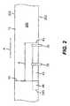
- FIG. 2is a diagrammatic top view of a section of the conveyor belt and sensors of the printer of FIG. 1 .
- FIG. 3is a diagrammatic side view of the conveyor and sensors of FIG. 2 .
- FIG. 4is an enlarged cross-section view taken substantially along line IV-IV in FIG. 3 .
- FIG. 5is a flow chart showing details of detecting, sensing, and allocating, in an embodiment of the method.
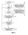
- FIG. 6is a flow chart showing details of optional features of the embodiment of FIG. 5 .
- the methodautomatically identifies a conveyor belt in a printer as being one of a plurality of belt types.
- the belt typeis defined by an applicable set of one or more control parameters for the printer. After the type of conveyor belt is automatically identified, appropriate control parameters are applied to the printer. In particular, as described above, sheet feed cycles of the printer can be set in accordance with the type of conveyor belt identified.
- the conveyor beltis moved along a circuit within a printer through one or more printing stations.
- the conveyor beltis an endless loop and has a longitudinal marking.
- the conveyor belthas a main portion between a pair of opposed, longitudinal edges.
- the main portion, which receives the sheets to be printed,is transparent.
- the markingis an opaque, longitudinal streak disposed in one of the edges.
- a start and an end of a longitudinal marking on the conveyor beltare detected as the conveyor belt is moved.
- a distance of travel of the moving conveyor belt between detecting the start and the endis then sensed. This distance corresponds to the length of the marking and is also referred to herein as the “sensed marking length”.
- the manner in which the sensed marking length is determinedis not critical. For example, the distance of travel can be sensed directly from a timing signal encoder on a roller synchronized with the conveyor belt or the like. Distance of travel can also be sensed indirectly as an elapsed time of travel of the conveyor belt at a known speed.
- the sensed marking lengthis allocated to the nearest of a plurality of nominal marking lengths.
- Each nominal marking lengthis associated with a respective one of the belt types.
- the nominal marking lengthsare nominal, that is, each one includes a range of lengths about a “nominal” center value. The ranges can be selected to accommodate expected variations in conveyor belt speed and the like. The ranges are mutually exclusive to prevent ambiguity.
- the sensed marking lengthis allocated to a nominal marking length that has a range that is inclusive of the sensed marking length.
- the belt typedirectly provides applicable control parameters for the printer or is used to determine such parameters in a look-up table.
- the set of control parametersare then applied to the printer.
- a sensor used to detect the start and end of the markingis a light barrier (such as a photocell and a light emitter).
- a light barrierdetects the leading and trailing edges of the marking as they pass through the light barrier, blocking or admitting the light from the emitter, respectively.
- the conveyor belthas a seam which is spaced a predetermined distance away from the start of the marking in the direction of travel of the conveyor belt.
- the position of the seamis calculated from the detected start of the marking. It is preferred that the predetermined distance is independent of the type of conveyor belt. In other words, in all of the different types of belts, the distance from the start of the marking to the seam is the same, but the distances between the ends of the different markings and the seam are different.
- the markingextends over the seam. This allows the start of the marking to be conveniently positioned for indicating the seam location without constraining the length of the marking.
- the type of transparent conveyor beltis automatically identified after each re-start of the printer before a printing process is begun.
- the printerfirst undergoes a shut-down and then restarts.
- the restartenables detecting of the start and end of the marking, sensing of the marking length, and the determination of the belt type.
- the identification of the conveyor beltis enabled when an access flap is opened.
- a belt access signalis generated when an access flap of the printer is moved from a closed position to an open position.
- the access flapdenies operator access to the conveyor belt when the access flap is in the closed position and allows operator access only when the access flap is in the open position.
- the conveyor belthas an alignment indicator, such as a laterally inward portion of the start of the marking or a separate indicator disposed on the other edge.
- an offset between the start and the indicatoris sensed.
- a cross-track alignment of the conveyor belt relative to the positions of the sensorsis computed from the offset.
- the sensor used to detect the indicatorcan be a light barrier, as earlier discussed.
- the conveyor belthas a side-to-side dimension that defines a cross-track axis that is optimally aligned perpendicular to the direction of travel of the conveyor belt.
- the longitudinal dimension of the conveyor beltdefines a longitudinal axis that is optimally parallel to the direction of travel of the conveyor belt.
- the start of the marking and the indicatorare at known positions in the longitudinal direction. The detection of the start and the detection of the indicator coincide or occur at a predetermined separation. Any further separation is an offset that indicates a cross-track misalignment of the conveyor belt.
- detecting the start of the marking with a first sensorinitializes a second sensor that is then used to detect the indicator.
- the cross-track alignment of the beltis then determined. This allows the second sensor to only be activated, when needed to detect the indicator.
- FIG. 1shows a particular embodiment, in which the printer is an electrophotographic printer 1 .
- the printer 1has a sheet alignment unit 3 , a transport unit 5 , a plurality of printing mechanisms 7 , and a fixing station 9 .
- Other features, such as sheet feeders and deliverers, and other sheet guide paths,are not shown in detail. These and other features are well known to those of skill in the art.
- the sheet alignment unit 3transfers a sheet of media to be printed to the transport unit 5 in an aligned and controlled manner.
- the transport unit 5includes an endless conveyor belt 12 and a plurality of rollers 14 , about which the conveyor belt 12 is guided. At least one of the rollers 14 is coupled to a drive unit, which moves the conveyor belt 12 in a circulatory direction as indicated by arrow A. In a particular embodiment, the conveyor belt 12 is wrapped around this driven roller 14 at an angle of at least 90° in order to avoid any slippage between the conveyor belt 12 and the corresponding roller 14 .
- Driven roller 14has an angular position sensor (also referred to as an encoder) 16 , which makes it possible to determine the movement and the position of the conveyor belt 12 .
- the conveyor belt 12is guided to move a sheet to be printed through a plurality of printing mechanisms 7 .
- Each of the printing mechanisms 7has an imaging cylinder 20 , a writing device 22 , a toner station 24 , an intermediate cylinder 26 , and an impression cylinder 28 .
- the imaging cylinder 20has a surface onto which an electrostatically charged image can be applied in a known way by the writing device 22 .
- toner particlesadhere to the electrostatically charged image regions on the surface of the imaging cylinder 20 and are conveyed onwards.
- the toner particlesare then transferred to the respective intermediate cylinder 26 , which has a rubber coating.
- the toner particlesare then transferred onto a sheet to be printed located on the conveyor belt 12 , the transfer taking place in a nip region between the intermediate cylinder 26 and the impression cylinder 28 .
- an electrostatic chargecan be generated on the conveyor belt 12 by the impression cylinder 28 .
- FIG. 1four printing mechanisms 7 are shown which are suitable, for example, for applying toner images of different color separations, for example, in the colors cyan, magenta, yellow and black.
- the printing mechanismsare controlled in a known way so that the color separations are applied in registration over one another on the sheet of media to be printed so as to produce a multi-colored image.
- a number of printing mechanisms different to that shown in FIG. 1can also or instead be provided.
- the respective printing mechanisms 7can apply the toner images directly onto the media or indirectly via and intermediate element, which then applies the whole toner image to the media to be printed.
- the fixing station 9is disposed downstream of the printing mechanisms 7 and has a fuser that fuses the toner image onto the sheet of media.
- Sensor 30can, for example, be a sheet identification sensor, which identifies the front edge of a sheet on the conveyor belt 12 during a print job and correspondingly controls the writing device 22 of the printing modules 7 .
- the identification of the sheet by the sensor 30is, for example, correlated with the data of the angular position sensor 16 in order to provide corresponding control of the writing device 22 of the printing modules 7 .
- the sensor 31is used in calibration runs of the electrophotographic printer. In such calibration runs, a plurality of index marks, such as at least one toner line for each printing mechanism, are printed onto media or onto the conveyor belt 12 , and are then detected by the sensor 31 . In this way, the control of the writing devices 22 can be calibrated in a known manner so that images can be printed in registration.
- FIG. 2shows a diagrammatic top view of a section of the conveyor belt in the region of the sensors 32 , 33 .
- FIG. 3shows a diagrammatic side view of the section of the conveyor belt, and
- FIG. 4shows a diagrammatic sectional view along line IV-IV in FIG. 3 .
- the conveyor belt 12is a conveyor belt of the previously described type with a seam 40 .
- the seam 40is formed by adhesively bonding, welding or connecting in some other way overlapping ends of a conveyor belt material.
- the conveyor belthas a transparent main portion 200 between a pair of opposed longitudinal edges 202 .
- One side edge 202 of the conveyor belt 12has a marking 42 , in the form of an opaque streak.
- the front edge or start 43 of the marking 42is a pre-determined distance ‘d’ from the seam 40 in the direction of travel.
- the marking 42has an overall length dependent upon the type of conveyor belt 12 which can extend, dependently upon belt type, over the seam 40 , as shown by the dashed region 44 to a rear edge or end 243 . In a particular embodiment, the overall length of the marking 42 and the distance ‘d’ between the leading edge 43 and the seam 40 always remains the same.
- the sensor 32is disposed downstream in relation to the sensor 33 in the direction of travel A of the conveyor belt 12 . Both sensors 32 , 33 encompass the conveyor belt 12 on the side on which the marking 42 is provided. This is shown diagrammatically for the sensor 33 in FIG. 4 .
- the sensor 32has a light emitter, which directs a beam of light through the conveyor belt 12 onto a corresponding detector. Since the conveyor belt 12 is transparent, the beam of light can normally be detected by the detector. When the opaque marking 42 enters the path of the beam between the emitter and the detector, the detector is shaded and a corresponding start signal is emitted. When the marking emerges again from the path of the beam, the beam of light hits the detector again and a corresponding end signal can be emitted.
- the sensor 32is therefore capable of identifying both the front edge 43 and rear edge 243 of the marking by corresponding light/dark and dark/light transitions.
- the sensor 33can be in the form of a so-called line sensor, which has a linearly arranged plurality of light emitters (indicated by 50 ) and a linear arrangement of light detectors (indicated by 52 ).
- the width of the marking, in a cross-track directionis broadened. If the start of the marking 42 on the conveyor belt 12 now comes into the region of the sensor 33 , a larger or smaller proportion of detectors 52 in relation to emitters 50 is shadowed in accordance with a cross-track position of the conveyor belt 12 . This enables the cross-track position of the conveyor belt to be determined and thus corrected by appropriate adjustment means.
- FIG. 5is an exemplary flow chart.
- the processis started by the conveyor belt being set in circulatory motion and the sensor 32 being activated.
- the process controlpasses to decision block 62 , where a determination is made whether the passage of light through the conveyor belt 12 is free, i.e. whether light passes from the emitter of the sensor 32 through the conveyor belt 12 to the detector. If this is the case, the process continues to pass through the decision block until the passage of light is covered, which indicates that the front edge of the marking 42 has passed into the path of the beam of the sensor 32 . At this point in time, a first belt position of the conveyor belt in the direction of travel is determined in block 64 using the angular position sensor 16 . Next, the process passes to decision block 66 , in which a determination is made whether the passage of light is free. If this is not the case, the process is repeated until the passage of light is free again.
- the processpasses on to block 68 , in which a second belt position of the conveyor belt in the direction of travel is now determined using the angular position sensor 16 .
- the length of the markingis then determined in block 70 .
- the type of conveyor beltis then determined in accordance with the length of the marking, for example, by referring to a look-up table, in which different belt types are specified for different marking lengths.
- the processpasses to block 73 , in which the automatic identification process is ended.
- the process control of the printerapplies control parameters for the type of conveyor belt being used in the printer.
- FIG. 6a process sequence for correcting a cross-track alignment of the conveyor belt and seam identification is shown in greater detail.
- the sensor 32is activated while the conveyor belt is driven.
- decision block 76a determination is made whether the passage of light through the conveyor belt 12 is free. The process is continued until a determination is made that the passage of light is blocked, which indicates shadowing of the sensor by the marking 42 . The process can then optionally, as shown by the dashed lines, determine the positioning of the seam.
- the position of the seamis determined by means of the known distance between the leading edge of the marking and the seam.
- the printing process and the sheet feeding of the printerare controlled in accordance with the position of the seam, such that no sheets are placed on the seam. The process then passes back to decision block 76 .
- the processpasses to block 82 , after it has been determined that the passage of light is blocked.
- block 82measurement of the cross-track position of the belt is initiated, because, as can be seen in FIG. 2 , at this point in time the marking 42 is located in the region of the sensor 33 .
- the corresponding measurement of the cross-track position of the beltis implemented in block 84 .
- decision block 86a determination is made whether the cross-track position of the belt lies within pre-specified limits. If this is the case, the process loops back to decision block 76 . If the cross-track position of the belt lies outside of the pre-specified limits, the process then passes to block 88 , in which the cross-track track position of the belt is corrected. Next, the process loops back to decision block 76 . When the whole printing process has ended, the process according to FIG. 6 is also ended.
- the process sequence described above for automatically identifying the type of conveyor beltcan be automatically implemented each time the printer is re-started or each time the operator is allowed access to the conveyor belt. This can be initiated, for example, by an appropriate signal when opening an access cover, which would enable access to the conveyor belt and thus a change thereof.
- the methodcan be varied as known to those of skill in the art. For example, the above presumes that the conveyor belt has a seam. The method can also be applied to a seamless conveyor belt. The design of the respective sensors can also be changed. The length of the marking can be determined from a known belt circulation speed and the temporal difference in identifying the start and end of the marking.
- an alternative method for automatically identifying a type of conveyor beltwhich is moved along a circulatory path within the printer, through at least one printing station.
- the conveyor beltis moved past a marking unit, which applies a specific electric charge image (a non-patterned or patterned area of electric charge) to a region of the conveyor belt.
- the region of the conveyor belt to which the electric charge image has been appliedis then moved along the circuit.
- the charged region of the beltmoves past a sensor, which samples the electric charge remaining on the conveyor belt and determines the type of conveyor belt based on the change in the electric charge image.
- the electric chargeis applied by an impression cylinder of a printing module of an electrophotographic printer.
- the impression cylinderis in contact with the conveyor belt and supplies an electric charge for facilitating the transfer of toner to the print media during a printing mode of the printer.
Landscapes
- Physics & Mathematics (AREA)
- General Physics & Mathematics (AREA)
- Electrostatic Charge, Transfer And Separation In Electrography (AREA)
- Controlling Sheets Or Webs (AREA)
Abstract
Description
Claims (18)
Applications Claiming Priority (6)
| Application Number | Priority Date | Filing Date | Title |
|---|---|---|---|
| DE102006043728 | 2006-09-13 | ||
| DE102006043728.4 | 2006-09-13 | ||
| DE102006043728 | 2006-09-13 | ||
| DE102007040588.1 | 2007-08-28 | ||
| DE102007040588 | 2007-08-28 | ||
| DE102007040588ADE102007040588B4 (en) | 2006-09-13 | 2007-08-28 | Method for operating a printing machine with a transparent conveyor belt |
Publications (2)
| Publication Number | Publication Date |
|---|---|
| US20080061998A1 US20080061998A1 (en) | 2008-03-13 |
| US7812735B2true US7812735B2 (en) | 2010-10-12 |
Family
ID=39169022
Family Applications (1)
| Application Number | Title | Priority Date | Filing Date |
|---|---|---|---|
| US11/853,914Expired - Fee RelatedUS7812735B2 (en) | 2006-09-13 | 2007-09-12 | Method for automatically identifying a type of transparent conveyor belt |
Country Status (2)
| Country | Link |
|---|---|
| US (1) | US7812735B2 (en) |
| DE (1) | DE102007040588B4 (en) |
Cited By (4)
| Publication number | Priority date | Publication date | Assignee | Title |
|---|---|---|---|---|
| US20100310282A1 (en)* | 2009-06-03 | 2010-12-09 | Xerox Corporation | Printing method, apparatus and systems for generating a reg sync signal |
| US20130201246A1 (en)* | 2012-02-07 | 2013-08-08 | Jeffrey Belbeck | Apparatus and method for paper position sensing using transparent transport belt |
| US10831141B2 (en)* | 2019-01-28 | 2020-11-10 | Canon Kabushiki Kaisha | Image forming apparatus |
| US11408489B2 (en)* | 2018-10-23 | 2022-08-09 | Roche Diagnostics Operations, Inc. | Belt drive system |
Families Citing this family (3)
| Publication number | Priority date | Publication date | Assignee | Title |
|---|---|---|---|---|
| DE102011009823A1 (en) | 2011-01-31 | 2012-08-16 | Eastman Kodak Co. | Conveyor belt for conveying printing material through printing machine, comprises opaque marker, which has rectangular marker portion that is strip-shaped along running direction of conveyor belt |
| JP6748942B2 (en)* | 2016-07-15 | 2020-09-02 | 株式会社リコー | Belt device, fixing device, and image forming device |
| DE102016012500A1 (en)* | 2016-10-19 | 2018-04-19 | Texmag Gmbh Vertriebsgesellschaft | Method and device for detecting the position of a moving web |
Citations (16)
| Publication number | Priority date | Publication date | Assignee | Title |
|---|---|---|---|---|
| US4847660A (en)* | 1985-10-25 | 1989-07-11 | Colorocs Corporation | Method and apparatus for registration control in an electrophotographic print engine |
| US4967227A (en)* | 1988-09-09 | 1990-10-30 | Brother Kogyo Kabushiki Kaisha | Color image recording apparatus with mask member registering mechanism |
| US5291245A (en)* | 1993-03-23 | 1994-03-01 | Xerox Corporation | Photoreceptor belt seam detection and process control |
| US5574527A (en)* | 1995-09-25 | 1996-11-12 | Xerox Corporation | Multiple use of a sensor in a printing machine |
| US5613784A (en)* | 1994-08-31 | 1997-03-25 | Fuji Xerox Co., Ltd. | Printer and printing method thereby |
| US5966573A (en)* | 1998-10-08 | 1999-10-12 | Xerox Corporation | Seamed flexible electrostatographic imaging belt having a permanent localized solid attribute |
| US5995802A (en)* | 1996-07-08 | 1999-11-30 | Fuji Xerox Co., Ltd. | Image forming apparatus |
| DE10013982A1 (en) | 1999-04-07 | 2000-10-12 | Nexpress Solutions Llc | Light barrier arrangement has at least one beam forming sufficiently narrow bar in direction of edge to be detected light barrier signals are combined logically in common evaluation unit |
| JP2001051518A (en) | 1999-08-12 | 2001-02-23 | Ricoh Co Ltd | Image forming device |
| US20030179271A1 (en)* | 2002-03-22 | 2003-09-25 | Wray Russ | In-line marking system |
| EP1376256A2 (en) | 2002-06-17 | 2004-01-02 | Ricoh Company, Ltd. | Image forming apparatus and method using an intermediate transfer belt with a color image |
| DE10318997A1 (en) | 2003-04-25 | 2005-01-27 | Nexpress Solutions Llc | Method and control device for avoiding register errors |
| JP2005195818A (en) | 2004-01-06 | 2005-07-21 | Fuji Xerox Co Ltd | Electric apparatus and abnormal component detection device for apparatus |
| US7021738B2 (en)* | 2003-10-10 | 2006-04-04 | Hewlett-Packard Development Company, L.P. | Multi-color printer |
| US20060228129A1 (en) | 2003-01-31 | 2006-10-12 | Canon Kabushiki Kaisha | Image forming apparatus and method for controlling an image forming operation of primarily transferring an image onto an intermediate transfer member |
| US20070058992A1 (en)* | 2005-09-13 | 2007-03-15 | Canon Kabushiki Kaisha | Image forming apparatus |
Family Cites Families (3)
| Publication number | Priority date | Publication date | Assignee | Title |
|---|---|---|---|---|
| US228129A (en)* | 1880-03-25 | 1880-05-25 | Marion H Simmons | Self-locking clevis |
| DE3834232A1 (en)* | 1987-10-09 | 1989-04-20 | Brother Ind Ltd | DEVICE AND METHOD FOR RECORDING A COLOR IMAGE |
| JP2000132048A (en)* | 1998-10-27 | 2000-05-12 | Canon Inc | Image forming device |
- 2007
- 2007-08-28DEDE102007040588Apatent/DE102007040588B4/ennot_activeExpired - Fee Related
- 2007-09-12USUS11/853,914patent/US7812735B2/ennot_activeExpired - Fee Related
Patent Citations (18)
| Publication number | Priority date | Publication date | Assignee | Title |
|---|---|---|---|---|
| US4847660A (en)* | 1985-10-25 | 1989-07-11 | Colorocs Corporation | Method and apparatus for registration control in an electrophotographic print engine |
| US4967227A (en)* | 1988-09-09 | 1990-10-30 | Brother Kogyo Kabushiki Kaisha | Color image recording apparatus with mask member registering mechanism |
| US5291245A (en)* | 1993-03-23 | 1994-03-01 | Xerox Corporation | Photoreceptor belt seam detection and process control |
| US5613784A (en)* | 1994-08-31 | 1997-03-25 | Fuji Xerox Co., Ltd. | Printer and printing method thereby |
| US5574527A (en)* | 1995-09-25 | 1996-11-12 | Xerox Corporation | Multiple use of a sensor in a printing machine |
| US5995802A (en)* | 1996-07-08 | 1999-11-30 | Fuji Xerox Co., Ltd. | Image forming apparatus |
| US5966573A (en)* | 1998-10-08 | 1999-10-12 | Xerox Corporation | Seamed flexible electrostatographic imaging belt having a permanent localized solid attribute |
| DE10013982A1 (en) | 1999-04-07 | 2000-10-12 | Nexpress Solutions Llc | Light barrier arrangement has at least one beam forming sufficiently narrow bar in direction of edge to be detected light barrier signals are combined logically in common evaluation unit |
| JP2001051518A (en) | 1999-08-12 | 2001-02-23 | Ricoh Co Ltd | Image forming device |
| US20030179271A1 (en)* | 2002-03-22 | 2003-09-25 | Wray Russ | In-line marking system |
| US6793302B2 (en)* | 2002-03-22 | 2004-09-21 | Microboards Technology, Llc | In-line marking system |
| EP1376256A2 (en) | 2002-06-17 | 2004-01-02 | Ricoh Company, Ltd. | Image forming apparatus and method using an intermediate transfer belt with a color image |
| US20060228129A1 (en) | 2003-01-31 | 2006-10-12 | Canon Kabushiki Kaisha | Image forming apparatus and method for controlling an image forming operation of primarily transferring an image onto an intermediate transfer member |
| DE10318997A1 (en) | 2003-04-25 | 2005-01-27 | Nexpress Solutions Llc | Method and control device for avoiding register errors |
| US7021738B2 (en)* | 2003-10-10 | 2006-04-04 | Hewlett-Packard Development Company, L.P. | Multi-color printer |
| JP2005195818A (en) | 2004-01-06 | 2005-07-21 | Fuji Xerox Co Ltd | Electric apparatus and abnormal component detection device for apparatus |
| US20070058992A1 (en)* | 2005-09-13 | 2007-03-15 | Canon Kabushiki Kaisha | Image forming apparatus |
| US7522849B2 (en)* | 2005-09-13 | 2009-04-21 | Canon Kabushiki Kaisha | Image forming apparatus with belt recognition device |
Cited By (6)
| Publication number | Priority date | Publication date | Assignee | Title |
|---|---|---|---|---|
| US20100310282A1 (en)* | 2009-06-03 | 2010-12-09 | Xerox Corporation | Printing method, apparatus and systems for generating a reg sync signal |
| US8180266B2 (en)* | 2009-06-03 | 2012-05-15 | Xerox Corporation | Method, apparatus and systems for registering the transfer of an image associated with a printing device |
| US20130201246A1 (en)* | 2012-02-07 | 2013-08-08 | Jeffrey Belbeck | Apparatus and method for paper position sensing using transparent transport belt |
| US8857947B2 (en)* | 2012-02-07 | 2014-10-14 | Delphax Technologies Inc. | Apparatus and method for paper position sensing using transparent transport belt |
| US11408489B2 (en)* | 2018-10-23 | 2022-08-09 | Roche Diagnostics Operations, Inc. | Belt drive system |
| US10831141B2 (en)* | 2019-01-28 | 2020-11-10 | Canon Kabushiki Kaisha | Image forming apparatus |
Also Published As
| Publication number | Publication date |
|---|---|
| DE102007040588A1 (en) | 2008-04-24 |
| US20080061998A1 (en) | 2008-03-13 |
| DE102007040588B4 (en) | 2011-05-12 |
Similar Documents
| Publication | Publication Date | Title |
|---|---|---|
| US7812735B2 (en) | Method for automatically identifying a type of transparent conveyor belt | |
| US7548316B2 (en) | System and method for lead edge and trail edge sheet constraint and curl sensing | |
| US8005388B2 (en) | Media velocity, media present and bubble control in an electrophotographic process | |
| US20020081132A1 (en) | Printing system | |
| US11148891B2 (en) | Sheet conveying device and image forming apparatus incorporating the sheet conveying device | |
| CA2435403C (en) | Lead edge paper curl sensor | |
| KR101321459B1 (en) | Image forming apparatus | |
| JP5445221B2 (en) | Mark detection method | |
| CN101566815B (en) | Image forming apparatus | |
| JP2017114659A (en) | Sheet length measurement device, image formation apparatus and sheet material detection method | |
| US20090194938A1 (en) | Image forming apparatus | |
| US7778559B2 (en) | Method to improve data collection accuracy by improved windowing in a toner density control system | |
| US8213847B2 (en) | Image forming apparatus including transport unit | |
| US5126762A (en) | Recording sheet used with image recording apparatus, and method and apparatus for forming image | |
| US7914001B2 (en) | Systems and methods for determining skew contribution in lateral sheet registration | |
| JP2009128440A (en) | Image forming apparatus | |
| JP7085133B2 (en) | Conveyor device, image forming device | |
| US6137981A (en) | Apparatus for forming multiple toner images in register with each other on a substrate | |
| CN103576492B (en) | Image processing system | |
| JP2002532739A (en) | Electrophotographic printing device with sensor for slip recognition | |
| US7162956B2 (en) | Method and control device for determining a register error | |
| US8437681B2 (en) | Printer or copier for printing an endless support material comprising transversal folds, and method for controlling such a printer or copier | |
| JP2004149265A (en) | Image forming device | |
| CN101571687B (en) | image forming device | |
| JP2007060516A (en) | Image photographing system and image-forming device |
Legal Events
| Date | Code | Title | Description |
|---|---|---|---|
| AS | Assignment | Owner name:EASTMAN KODAK COMPANY, NEW YORK Free format text:ASSIGNMENT OF ASSIGNORS INTEREST;ASSIGNORS:KAHL, DIRK;PETERSEN, RALPH;PIEREL, FRANK;AND OTHERS;REEL/FRAME:020057/0548;SIGNING DATES FROM 20071018 TO 20071029 Owner name:EASTMAN KODAK COMPANY, NEW YORK Free format text:ASSIGNMENT OF ASSIGNORS INTEREST;ASSIGNORS:KAHL, DIRK;PETERSEN, RALPH;PIEREL, FRANK;AND OTHERS;SIGNING DATES FROM 20071018 TO 20071029;REEL/FRAME:020057/0548 | |
| STCF | Information on status: patent grant | Free format text:PATENTED CASE | |
| AS | Assignment | Owner name:CITICORP NORTH AMERICA, INC., AS AGENT, NEW YORK Free format text:SECURITY INTEREST;ASSIGNORS:EASTMAN KODAK COMPANY;PAKON, INC.;REEL/FRAME:028201/0420 Effective date:20120215 | |
| AS | Assignment | Owner name:WILMINGTON TRUST, NATIONAL ASSOCIATION, AS AGENT, Free format text:PATENT SECURITY AGREEMENT;ASSIGNORS:EASTMAN KODAK COMPANY;PAKON, INC.;REEL/FRAME:030122/0235 Effective date:20130322 Owner name:WILMINGTON TRUST, NATIONAL ASSOCIATION, AS AGENT, MINNESOTA Free format text:PATENT SECURITY AGREEMENT;ASSIGNORS:EASTMAN KODAK COMPANY;PAKON, INC.;REEL/FRAME:030122/0235 Effective date:20130322 | |
| AS | Assignment | Owner name:BARCLAYS BANK PLC, AS ADMINISTRATIVE AGENT, NEW YORK Free format text:INTELLECTUAL PROPERTY SECURITY AGREEMENT (SECOND LIEN);ASSIGNORS:EASTMAN KODAK COMPANY;FAR EAST DEVELOPMENT LTD.;FPC INC.;AND OTHERS;REEL/FRAME:031159/0001 Effective date:20130903 Owner name:JPMORGAN CHASE BANK, N.A., AS ADMINISTRATIVE, DELAWARE Free format text:INTELLECTUAL PROPERTY SECURITY AGREEMENT (FIRST LIEN);ASSIGNORS:EASTMAN KODAK COMPANY;FAR EAST DEVELOPMENT LTD.;FPC INC.;AND OTHERS;REEL/FRAME:031158/0001 Effective date:20130903 Owner name:EASTMAN KODAK COMPANY, NEW YORK Free format text:RELEASE OF SECURITY INTEREST IN PATENTS;ASSIGNORS:CITICORP NORTH AMERICA, INC., AS SENIOR DIP AGENT;WILMINGTON TRUST, NATIONAL ASSOCIATION, AS JUNIOR DIP AGENT;REEL/FRAME:031157/0451 Effective date:20130903 Owner name:BARCLAYS BANK PLC, AS ADMINISTRATIVE AGENT, NEW YO Free format text:INTELLECTUAL PROPERTY SECURITY AGREEMENT (SECOND LIEN);ASSIGNORS:EASTMAN KODAK COMPANY;FAR EAST DEVELOPMENT LTD.;FPC INC.;AND OTHERS;REEL/FRAME:031159/0001 Effective date:20130903 Owner name:PAKON, INC., NEW YORK Free format text:RELEASE OF SECURITY INTEREST IN PATENTS;ASSIGNORS:CITICORP NORTH AMERICA, INC., AS SENIOR DIP AGENT;WILMINGTON TRUST, NATIONAL ASSOCIATION, AS JUNIOR DIP AGENT;REEL/FRAME:031157/0451 Effective date:20130903 Owner name:JPMORGAN CHASE BANK, N.A., AS ADMINISTRATIVE, DELA Free format text:INTELLECTUAL PROPERTY SECURITY AGREEMENT (FIRST LIEN);ASSIGNORS:EASTMAN KODAK COMPANY;FAR EAST DEVELOPMENT LTD.;FPC INC.;AND OTHERS;REEL/FRAME:031158/0001 Effective date:20130903 Owner name:BANK OF AMERICA N.A., AS AGENT, MASSACHUSETTS Free format text:INTELLECTUAL PROPERTY SECURITY AGREEMENT (ABL);ASSIGNORS:EASTMAN KODAK COMPANY;FAR EAST DEVELOPMENT LTD.;FPC INC.;AND OTHERS;REEL/FRAME:031162/0117 Effective date:20130903 | |
| FPAY | Fee payment | Year of fee payment:4 | |
| AS | Assignment | Owner name:MIDWEST ATHLETICS AND SPORTS ALLIANCE LLC, NEBRASK Free format text:ASSIGNMENT OF ASSIGNORS INTEREST;ASSIGNOR:EASTMAN KODAK COMPANY;REEL/FRAME:044811/0502 Effective date:20171120 | |
| AS | Assignment | Owner name:MIDWEST ATHLETICS AND SPORTS ALLIANCE LLC, NEBRASK Free format text:ASSIGNMENT OF ASSIGNORS INTEREST;ASSIGNOR:EASTMAN KODAK COMPANY;REEL/FRAME:044811/0245 Effective date:20171120 | |
| AS | Assignment | Owner name:EASTMAN KODAK COMPANY, NEW YORK Free format text:RELEASE BY SECURED PARTY;ASSIGNOR:JP MORGAN CHASE BANK N.A.;REEL/FRAME:045095/0317 Effective date:20171115 Owner name:EASTMAN KODAK COMPANY, NEW YORK Free format text:RELEASE BY SECURED PARTY;ASSIGNOR:BANK OF AMERICA N.A.;REEL/FRAME:045095/0299 Effective date:20171115 | |
| MAFP | Maintenance fee payment | Free format text:PAYMENT OF MAINTENANCE FEE, 8TH YEAR, LARGE ENTITY (ORIGINAL EVENT CODE: M1552) Year of fee payment:8 | |
| AS | Assignment | Owner name:FAR EAST DEVELOPMENT LTD., NEW YORK Free format text:RELEASE BY SECURED PARTY;ASSIGNOR:JP MORGAN CHASE BANK, N.A., AS ADMINISTRATIVE AGENT;REEL/FRAME:050239/0001 Effective date:20190617 Owner name:KODAK PORTUGUESA LIMITED, NEW YORK Free format text:RELEASE BY SECURED PARTY;ASSIGNOR:JP MORGAN CHASE BANK, N.A., AS ADMINISTRATIVE AGENT;REEL/FRAME:050239/0001 Effective date:20190617 Owner name:KODAK AVIATION LEASING LLC, NEW YORK Free format text:RELEASE BY SECURED PARTY;ASSIGNOR:JP MORGAN CHASE BANK, N.A., AS ADMINISTRATIVE AGENT;REEL/FRAME:050239/0001 Effective date:20190617 Owner name:KODAK (NEAR EAST), INC., NEW YORK Free format text:RELEASE BY SECURED PARTY;ASSIGNOR:JP MORGAN CHASE BANK, N.A., AS ADMINISTRATIVE AGENT;REEL/FRAME:050239/0001 Effective date:20190617 Owner name:PAKON, INC., NEW YORK Free format text:RELEASE BY SECURED PARTY;ASSIGNOR:JP MORGAN CHASE BANK, N.A., AS ADMINISTRATIVE AGENT;REEL/FRAME:050239/0001 Effective date:20190617 Owner name:CREO MANUFACTURING AMERICA LLC, NEW YORK Free format text:RELEASE BY SECURED PARTY;ASSIGNOR:JP MORGAN CHASE BANK, N.A., AS ADMINISTRATIVE AGENT;REEL/FRAME:050239/0001 Effective date:20190617 Owner name:KODAK IMAGING NETWORK, INC., NEW YORK Free format text:RELEASE BY SECURED PARTY;ASSIGNOR:JP MORGAN CHASE BANK, N.A., AS ADMINISTRATIVE AGENT;REEL/FRAME:050239/0001 Effective date:20190617 Owner name:KODAK PHILIPPINES, LTD., NEW YORK Free format text:RELEASE BY SECURED PARTY;ASSIGNOR:JP MORGAN CHASE BANK, N.A., AS ADMINISTRATIVE AGENT;REEL/FRAME:050239/0001 Effective date:20190617 Owner name:LASER PACIFIC MEDIA CORPORATION, NEW YORK Free format text:RELEASE BY SECURED PARTY;ASSIGNOR:JP MORGAN CHASE BANK, N.A., AS ADMINISTRATIVE AGENT;REEL/FRAME:050239/0001 Effective date:20190617 Owner name:QUALEX, INC., NEW YORK Free format text:RELEASE BY SECURED PARTY;ASSIGNOR:JP MORGAN CHASE BANK, N.A., AS ADMINISTRATIVE AGENT;REEL/FRAME:050239/0001 Effective date:20190617 Owner name:FPC, INC., NEW YORK Free format text:RELEASE BY SECURED PARTY;ASSIGNOR:JP MORGAN CHASE BANK, N.A., AS ADMINISTRATIVE AGENT;REEL/FRAME:050239/0001 Effective date:20190617 Owner name:EASTMAN KODAK COMPANY, NEW YORK Free format text:RELEASE BY SECURED PARTY;ASSIGNOR:JP MORGAN CHASE BANK, N.A., AS ADMINISTRATIVE AGENT;REEL/FRAME:050239/0001 Effective date:20190617 Owner name:NPEC, INC., NEW YORK Free format text:RELEASE BY SECURED PARTY;ASSIGNOR:JP MORGAN CHASE BANK, N.A., AS ADMINISTRATIVE AGENT;REEL/FRAME:050239/0001 Effective date:20190617 Owner name:KODAK AMERICAS, LTD., NEW YORK Free format text:RELEASE BY SECURED PARTY;ASSIGNOR:JP MORGAN CHASE BANK, N.A., AS ADMINISTRATIVE AGENT;REEL/FRAME:050239/0001 Effective date:20190617 Owner name:KODAK REALTY, INC., NEW YORK Free format text:RELEASE BY SECURED PARTY;ASSIGNOR:JP MORGAN CHASE BANK, N.A., AS ADMINISTRATIVE AGENT;REEL/FRAME:050239/0001 Effective date:20190617 | |
| AS | Assignment | Owner name:KODAK PHILIPPINES, LTD., NEW YORK Free format text:RELEASE BY SECURED PARTY;ASSIGNOR:JP MORGAN CHASE BANK, N.A., AS ADMINISTRATIVE AGENT;REEL/FRAME:049901/0001 Effective date:20190617 Owner name:KODAK AMERICAS, LTD., NEW YORK Free format text:RELEASE BY SECURED PARTY;ASSIGNOR:JP MORGAN CHASE BANK, N.A., AS ADMINISTRATIVE AGENT;REEL/FRAME:049901/0001 Effective date:20190617 Owner name:NPEC, INC., NEW YORK Free format text:RELEASE BY SECURED PARTY;ASSIGNOR:JP MORGAN CHASE BANK, N.A., AS ADMINISTRATIVE AGENT;REEL/FRAME:049901/0001 Effective date:20190617 Owner name:KODAK REALTY, INC., NEW YORK Free format text:RELEASE BY SECURED PARTY;ASSIGNOR:JP MORGAN CHASE BANK, N.A., AS ADMINISTRATIVE AGENT;REEL/FRAME:049901/0001 Effective date:20190617 Owner name:KODAK (NEAR EAST), INC., NEW YORK Free format text:RELEASE BY SECURED PARTY;ASSIGNOR:JP MORGAN CHASE BANK, N.A., AS ADMINISTRATIVE AGENT;REEL/FRAME:049901/0001 Effective date:20190617 Owner name:QUALEX, INC., NEW YORK Free format text:RELEASE BY SECURED PARTY;ASSIGNOR:JP MORGAN CHASE BANK, N.A., AS ADMINISTRATIVE AGENT;REEL/FRAME:049901/0001 Effective date:20190617 Owner name:EASTMAN KODAK COMPANY, NEW YORK Free format text:RELEASE BY SECURED PARTY;ASSIGNOR:JP MORGAN CHASE BANK, N.A., AS ADMINISTRATIVE AGENT;REEL/FRAME:049901/0001 Effective date:20190617 Owner name:LASER PACIFIC MEDIA CORPORATION, NEW YORK Free format text:RELEASE BY SECURED PARTY;ASSIGNOR:JP MORGAN CHASE BANK, N.A., AS ADMINISTRATIVE AGENT;REEL/FRAME:049901/0001 Effective date:20190617 Owner name:PAKON, INC., NEW YORK Free format text:RELEASE BY SECURED PARTY;ASSIGNOR:JP MORGAN CHASE BANK, N.A., AS ADMINISTRATIVE AGENT;REEL/FRAME:049901/0001 Effective date:20190617 Owner name:PFC, INC., NEW YORK Free format text:RELEASE BY SECURED PARTY;ASSIGNOR:JP MORGAN CHASE BANK, N.A., AS ADMINISTRATIVE AGENT;REEL/FRAME:049901/0001 Effective date:20190617 Owner name:CREO MANUFACTURING AMERICA LLC, NEW YORK Free format text:RELEASE BY SECURED PARTY;ASSIGNOR:JP MORGAN CHASE BANK, N.A., AS ADMINISTRATIVE AGENT;REEL/FRAME:049901/0001 Effective date:20190617 Owner name:KODAK IMAGING NETWORK, INC., NEW YORK Free format text:RELEASE BY SECURED PARTY;ASSIGNOR:JP MORGAN CHASE BANK, N.A., AS ADMINISTRATIVE AGENT;REEL/FRAME:049901/0001 Effective date:20190617 Owner name:FAR EAST DEVELOPMENT LTD., NEW YORK Free format text:RELEASE BY SECURED PARTY;ASSIGNOR:JP MORGAN CHASE BANK, N.A., AS ADMINISTRATIVE AGENT;REEL/FRAME:049901/0001 Effective date:20190617 Owner name:KODAK AVIATION LEASING LLC, NEW YORK Free format text:RELEASE BY SECURED PARTY;ASSIGNOR:JP MORGAN CHASE BANK, N.A., AS ADMINISTRATIVE AGENT;REEL/FRAME:049901/0001 Effective date:20190617 Owner name:KODAK PORTUGUESA LIMITED, NEW YORK Free format text:RELEASE BY SECURED PARTY;ASSIGNOR:JP MORGAN CHASE BANK, N.A., AS ADMINISTRATIVE AGENT;REEL/FRAME:049901/0001 Effective date:20190617 | |
| AS | Assignment | Owner name:KODAK (NEAR EAST) INC., NEW YORK Free format text:RELEASE BY SECURED PARTY;ASSIGNOR:BARCLAYS BANK PLC;REEL/FRAME:052773/0001 Effective date:20170202 Owner name:QUALEX INC., NEW YORK Free format text:RELEASE BY SECURED PARTY;ASSIGNOR:BARCLAYS BANK PLC;REEL/FRAME:052773/0001 Effective date:20170202 Owner name:NPEC INC., NEW YORK Free format text:RELEASE BY SECURED PARTY;ASSIGNOR:BARCLAYS BANK PLC;REEL/FRAME:052773/0001 Effective date:20170202 Owner name:FAR EAST DEVELOPMENT LTD., NEW YORK Free format text:RELEASE BY SECURED PARTY;ASSIGNOR:BARCLAYS BANK PLC;REEL/FRAME:052773/0001 Effective date:20170202 Owner name:FPC INC., NEW YORK Free format text:RELEASE BY SECURED PARTY;ASSIGNOR:BARCLAYS BANK PLC;REEL/FRAME:052773/0001 Effective date:20170202 Owner name:LASER PACIFIC MEDIA CORPORATION, NEW YORK Free format text:RELEASE BY SECURED PARTY;ASSIGNOR:BARCLAYS BANK PLC;REEL/FRAME:052773/0001 Effective date:20170202 Owner name:KODAK AMERICAS LTD., NEW YORK Free format text:RELEASE BY SECURED PARTY;ASSIGNOR:BARCLAYS BANK PLC;REEL/FRAME:052773/0001 Effective date:20170202 Owner name:KODAK REALTY INC., NEW YORK Free format text:RELEASE BY SECURED PARTY;ASSIGNOR:BARCLAYS BANK PLC;REEL/FRAME:052773/0001 Effective date:20170202 Owner name:KODAK PHILIPPINES LTD., NEW YORK Free format text:RELEASE BY SECURED PARTY;ASSIGNOR:BARCLAYS BANK PLC;REEL/FRAME:052773/0001 Effective date:20170202 Owner name:EASTMAN KODAK COMPANY, NEW YORK Free format text:RELEASE BY SECURED PARTY;ASSIGNOR:BARCLAYS BANK PLC;REEL/FRAME:052773/0001 Effective date:20170202 | |
| FEPP | Fee payment procedure | Free format text:MAINTENANCE FEE REMINDER MAILED (ORIGINAL EVENT CODE: REM.); ENTITY STATUS OF PATENT OWNER: LARGE ENTITY | |
| LAPS | Lapse for failure to pay maintenance fees | Free format text:PATENT EXPIRED FOR FAILURE TO PAY MAINTENANCE FEES (ORIGINAL EVENT CODE: EXP.); ENTITY STATUS OF PATENT OWNER: LARGE ENTITY | |
| STCH | Information on status: patent discontinuation | Free format text:PATENT EXPIRED DUE TO NONPAYMENT OF MAINTENANCE FEES UNDER 37 CFR 1.362 | |
| FP | Lapsed due to failure to pay maintenance fee | Effective date:20221012 |