US7811328B2 - System, device and methods for replacing the intervertebral disc with a magnetic or electromagnetic prosthesis - Google Patents
System, device and methods for replacing the intervertebral disc with a magnetic or electromagnetic prosthesisDownload PDFInfo
- Publication number
- US7811328B2 US7811328B2US11/118,277US11827705AUS7811328B2US 7811328 B2US7811328 B2US 7811328B2US 11827705 AUS11827705 AUS 11827705AUS 7811328 B2US7811328 B2US 7811328B2
- Authority
- US
- United States
- Prior art keywords
- end portion
- load bearing
- magnetic field
- prosthesis
- electrically conductive
- Prior art date
- Legal status (The legal status is an assumption and is not a legal conclusion. Google has not performed a legal analysis and makes no representation as to the accuracy of the status listed.)
- Active, expires
Links
- 238000000034methodMethods0.000titleclaimsdescription17
- 239000000463materialSubstances0.000claimsabstractdescription15
- 238000013016dampingMethods0.000claimsabstractdescription12
- 210000000988bone and boneAnatomy0.000claimsdescription21
- 239000004744fabricSubstances0.000claimsdescription10
- 238000002513implantationMethods0.000claimsdescription9
- 230000004044responseEffects0.000claimsdescription7
- 229920000620organic polymerPolymers0.000claimsdescription6
- 239000007787solidSubstances0.000claimsdescription6
- 238000004891communicationMethods0.000claimsdescription5
- 230000033001locomotionEffects0.000claimsdescription4
- 230000037081physical activityEffects0.000claimsdescription4
- 239000000835fiberSubstances0.000claimsdescription3
- 238000000926separation methodMethods0.000claims2
- 229920000642polymerPolymers0.000claims1
- 239000002759woven fabricSubstances0.000claims1
- 238000001356surgical procedureMethods0.000description4
- 239000012530fluidSubstances0.000description3
- 208000027418Wounds and injuryDiseases0.000description2
- 230000008901benefitEffects0.000description2
- 230000008878couplingEffects0.000description2
- 238000010168coupling processMethods0.000description2
- 238000005859coupling reactionMethods0.000description2
- 230000006378damageEffects0.000description2
- 208000014674injuryDiseases0.000description2
- 230000007246mechanismEffects0.000description2
- 239000002184metalSubstances0.000description2
- 238000012986modificationMethods0.000description2
- 230000004048modificationEffects0.000description2
- 229920001296polysiloxanePolymers0.000description2
- 241000310247Amyna axisSpecies0.000description1
- OKTJSMMVPCPJKN-UHFFFAOYSA-NCarbonChemical compound[C]OKTJSMMVPCPJKN-UHFFFAOYSA-N0.000description1
- 208000032170Congenital AbnormalitiesDiseases0.000description1
- 239000000853adhesiveSubstances0.000description1
- 230000001070adhesive effectEffects0.000description1
- 230000004075alterationEffects0.000description1
- 230000003466anti-cipated effectEffects0.000description1
- 239000002131composite materialSubstances0.000description1
- 230000002950deficientEffects0.000description1
- 201000010099diseaseDiseases0.000description1
- 208000037265diseases, disorders, signs and symptomsDiseases0.000description1
- 230000008030eliminationEffects0.000description1
- 238000003379elimination reactionMethods0.000description1
- 238000005516engineering processMethods0.000description1
- 238000002474experimental methodMethods0.000description1
- 239000011521glassSubstances0.000description1
- 229910002804graphiteInorganic materials0.000description1
- 239000010439graphiteSubstances0.000description1
- 230000036541healthEffects0.000description1
- 239000007943implantSubstances0.000description1
- 238000004519manufacturing processMethods0.000description1
- 230000000399orthopedic effectEffects0.000description1
- 230000001737promoting effectEffects0.000description1
- 230000009467reductionEffects0.000description1
- 238000011477surgical interventionMethods0.000description1
- 239000012209synthetic fiberSubstances0.000description1
- 229920002994synthetic fiberPolymers0.000description1
Images


Classifications
- A—HUMAN NECESSITIES
- A61—MEDICAL OR VETERINARY SCIENCE; HYGIENE
- A61F—FILTERS IMPLANTABLE INTO BLOOD VESSELS; PROSTHESES; DEVICES PROVIDING PATENCY TO, OR PREVENTING COLLAPSING OF, TUBULAR STRUCTURES OF THE BODY, e.g. STENTS; ORTHOPAEDIC, NURSING OR CONTRACEPTIVE DEVICES; FOMENTATION; TREATMENT OR PROTECTION OF EYES OR EARS; BANDAGES, DRESSINGS OR ABSORBENT PADS; FIRST-AID KITS
- A61F2/00—Filters implantable into blood vessels; Prostheses, i.e. artificial substitutes or replacements for parts of the body; Appliances for connecting them with the body; Devices providing patency to, or preventing collapsing of, tubular structures of the body, e.g. stents
- A61F2/02—Prostheses implantable into the body
- A61F2/30—Joints
- A61F2/44—Joints for the spine, e.g. vertebrae, spinal discs
- A61F2/442—Intervertebral or spinal discs, e.g. resilient
- A—HUMAN NECESSITIES
- A61—MEDICAL OR VETERINARY SCIENCE; HYGIENE
- A61F—FILTERS IMPLANTABLE INTO BLOOD VESSELS; PROSTHESES; DEVICES PROVIDING PATENCY TO, OR PREVENTING COLLAPSING OF, TUBULAR STRUCTURES OF THE BODY, e.g. STENTS; ORTHOPAEDIC, NURSING OR CONTRACEPTIVE DEVICES; FOMENTATION; TREATMENT OR PROTECTION OF EYES OR EARS; BANDAGES, DRESSINGS OR ABSORBENT PADS; FIRST-AID KITS
- A61F2/00—Filters implantable into blood vessels; Prostheses, i.e. artificial substitutes or replacements for parts of the body; Appliances for connecting them with the body; Devices providing patency to, or preventing collapsing of, tubular structures of the body, e.g. stents
- A61F2/02—Prostheses implantable into the body
- A61F2/30—Joints
- A61F2/30721—Accessories
- A61F2/30742—Bellows or hose-like seals; Sealing membranes
- A—HUMAN NECESSITIES
- A61—MEDICAL OR VETERINARY SCIENCE; HYGIENE
- A61F—FILTERS IMPLANTABLE INTO BLOOD VESSELS; PROSTHESES; DEVICES PROVIDING PATENCY TO, OR PREVENTING COLLAPSING OF, TUBULAR STRUCTURES OF THE BODY, e.g. STENTS; ORTHOPAEDIC, NURSING OR CONTRACEPTIVE DEVICES; FOMENTATION; TREATMENT OR PROTECTION OF EYES OR EARS; BANDAGES, DRESSINGS OR ABSORBENT PADS; FIRST-AID KITS
- A61F2/00—Filters implantable into blood vessels; Prostheses, i.e. artificial substitutes or replacements for parts of the body; Appliances for connecting them with the body; Devices providing patency to, or preventing collapsing of, tubular structures of the body, e.g. stents
- A61F2/02—Prostheses implantable into the body
- A61F2/48—Operating or control means, e.g. from outside the body, control of sphincters
- A61F2/482—Electrical means
- A—HUMAN NECESSITIES
- A61—MEDICAL OR VETERINARY SCIENCE; HYGIENE
- A61F—FILTERS IMPLANTABLE INTO BLOOD VESSELS; PROSTHESES; DEVICES PROVIDING PATENCY TO, OR PREVENTING COLLAPSING OF, TUBULAR STRUCTURES OF THE BODY, e.g. STENTS; ORTHOPAEDIC, NURSING OR CONTRACEPTIVE DEVICES; FOMENTATION; TREATMENT OR PROTECTION OF EYES OR EARS; BANDAGES, DRESSINGS OR ABSORBENT PADS; FIRST-AID KITS
- A61F2/00—Filters implantable into blood vessels; Prostheses, i.e. artificial substitutes or replacements for parts of the body; Appliances for connecting them with the body; Devices providing patency to, or preventing collapsing of, tubular structures of the body, e.g. stents
- A61F2/02—Prostheses implantable into the body
- A61F2/30—Joints
- A61F2002/30001—Additional features of subject-matter classified in A61F2/28, A61F2/30 and subgroups thereof
- A61F2002/30003—Material related properties of the prosthesis or of a coating on the prosthesis
- A61F2002/3006—Properties of materials and coating materials
- A61F2002/30079—Properties of materials and coating materials magnetic
- A—HUMAN NECESSITIES
- A61—MEDICAL OR VETERINARY SCIENCE; HYGIENE
- A61F—FILTERS IMPLANTABLE INTO BLOOD VESSELS; PROSTHESES; DEVICES PROVIDING PATENCY TO, OR PREVENTING COLLAPSING OF, TUBULAR STRUCTURES OF THE BODY, e.g. STENTS; ORTHOPAEDIC, NURSING OR CONTRACEPTIVE DEVICES; FOMENTATION; TREATMENT OR PROTECTION OF EYES OR EARS; BANDAGES, DRESSINGS OR ABSORBENT PADS; FIRST-AID KITS
- A61F2/00—Filters implantable into blood vessels; Prostheses, i.e. artificial substitutes or replacements for parts of the body; Appliances for connecting them with the body; Devices providing patency to, or preventing collapsing of, tubular structures of the body, e.g. stents
- A61F2/02—Prostheses implantable into the body
- A61F2/30—Joints
- A61F2002/30001—Additional features of subject-matter classified in A61F2/28, A61F2/30 and subgroups thereof
- A61F2002/30108—Shapes
- A61F2002/3011—Cross-sections or two-dimensional shapes
- A61F2002/30112—Rounded shapes, e.g. with rounded corners
- A61F2002/30133—Rounded shapes, e.g. with rounded corners kidney-shaped or bean-shaped
- A—HUMAN NECESSITIES
- A61—MEDICAL OR VETERINARY SCIENCE; HYGIENE
- A61F—FILTERS IMPLANTABLE INTO BLOOD VESSELS; PROSTHESES; DEVICES PROVIDING PATENCY TO, OR PREVENTING COLLAPSING OF, TUBULAR STRUCTURES OF THE BODY, e.g. STENTS; ORTHOPAEDIC, NURSING OR CONTRACEPTIVE DEVICES; FOMENTATION; TREATMENT OR PROTECTION OF EYES OR EARS; BANDAGES, DRESSINGS OR ABSORBENT PADS; FIRST-AID KITS
- A61F2/00—Filters implantable into blood vessels; Prostheses, i.e. artificial substitutes or replacements for parts of the body; Appliances for connecting them with the body; Devices providing patency to, or preventing collapsing of, tubular structures of the body, e.g. stents
- A61F2/02—Prostheses implantable into the body
- A61F2/30—Joints
- A61F2002/30001—Additional features of subject-matter classified in A61F2/28, A61F2/30 and subgroups thereof
- A61F2002/30316—The prosthesis having different structural features at different locations within the same prosthesis; Connections between prosthetic parts; Special structural features of bone or joint prostheses not otherwise provided for
- A61F2002/30329—Connections or couplings between prosthetic parts, e.g. between modular parts; Connecting elements
- A61F2002/30462—Connections or couplings between prosthetic parts, e.g. between modular parts; Connecting elements retained or tied with a rope, string, thread, wire or cable
- A—HUMAN NECESSITIES
- A61—MEDICAL OR VETERINARY SCIENCE; HYGIENE
- A61F—FILTERS IMPLANTABLE INTO BLOOD VESSELS; PROSTHESES; DEVICES PROVIDING PATENCY TO, OR PREVENTING COLLAPSING OF, TUBULAR STRUCTURES OF THE BODY, e.g. STENTS; ORTHOPAEDIC, NURSING OR CONTRACEPTIVE DEVICES; FOMENTATION; TREATMENT OR PROTECTION OF EYES OR EARS; BANDAGES, DRESSINGS OR ABSORBENT PADS; FIRST-AID KITS
- A61F2/00—Filters implantable into blood vessels; Prostheses, i.e. artificial substitutes or replacements for parts of the body; Appliances for connecting them with the body; Devices providing patency to, or preventing collapsing of, tubular structures of the body, e.g. stents
- A61F2/02—Prostheses implantable into the body
- A61F2/30—Joints
- A61F2002/30001—Additional features of subject-matter classified in A61F2/28, A61F2/30 and subgroups thereof
- A61F2002/30316—The prosthesis having different structural features at different locations within the same prosthesis; Connections between prosthetic parts; Special structural features of bone or joint prostheses not otherwise provided for
- A61F2002/30535—Special structural features of bone or joint prostheses not otherwise provided for
- A61F2002/30537—Special structural features of bone or joint prostheses not otherwise provided for adjustable
- A—HUMAN NECESSITIES
- A61—MEDICAL OR VETERINARY SCIENCE; HYGIENE
- A61F—FILTERS IMPLANTABLE INTO BLOOD VESSELS; PROSTHESES; DEVICES PROVIDING PATENCY TO, OR PREVENTING COLLAPSING OF, TUBULAR STRUCTURES OF THE BODY, e.g. STENTS; ORTHOPAEDIC, NURSING OR CONTRACEPTIVE DEVICES; FOMENTATION; TREATMENT OR PROTECTION OF EYES OR EARS; BANDAGES, DRESSINGS OR ABSORBENT PADS; FIRST-AID KITS
- A61F2/00—Filters implantable into blood vessels; Prostheses, i.e. artificial substitutes or replacements for parts of the body; Appliances for connecting them with the body; Devices providing patency to, or preventing collapsing of, tubular structures of the body, e.g. stents
- A61F2/02—Prostheses implantable into the body
- A61F2/30—Joints
- A61F2002/30001—Additional features of subject-matter classified in A61F2/28, A61F2/30 and subgroups thereof
- A61F2002/30316—The prosthesis having different structural features at different locations within the same prosthesis; Connections between prosthetic parts; Special structural features of bone or joint prostheses not otherwise provided for
- A61F2002/30535—Special structural features of bone or joint prostheses not otherwise provided for
- A61F2002/30563—Special structural features of bone or joint prostheses not otherwise provided for having elastic means or damping means, different from springs, e.g. including an elastomeric core or shock absorbers
- A—HUMAN NECESSITIES
- A61—MEDICAL OR VETERINARY SCIENCE; HYGIENE
- A61F—FILTERS IMPLANTABLE INTO BLOOD VESSELS; PROSTHESES; DEVICES PROVIDING PATENCY TO, OR PREVENTING COLLAPSING OF, TUBULAR STRUCTURES OF THE BODY, e.g. STENTS; ORTHOPAEDIC, NURSING OR CONTRACEPTIVE DEVICES; FOMENTATION; TREATMENT OR PROTECTION OF EYES OR EARS; BANDAGES, DRESSINGS OR ABSORBENT PADS; FIRST-AID KITS
- A61F2/00—Filters implantable into blood vessels; Prostheses, i.e. artificial substitutes or replacements for parts of the body; Appliances for connecting them with the body; Devices providing patency to, or preventing collapsing of, tubular structures of the body, e.g. stents
- A61F2/02—Prostheses implantable into the body
- A61F2/30—Joints
- A61F2002/30001—Additional features of subject-matter classified in A61F2/28, A61F2/30 and subgroups thereof
- A61F2002/30316—The prosthesis having different structural features at different locations within the same prosthesis; Connections between prosthetic parts; Special structural features of bone or joint prostheses not otherwise provided for
- A61F2002/30535—Special structural features of bone or joint prostheses not otherwise provided for
- A61F2002/30581—Special structural features of bone or joint prostheses not otherwise provided for having a pocket filled with fluid, e.g. liquid
- A—HUMAN NECESSITIES
- A61—MEDICAL OR VETERINARY SCIENCE; HYGIENE
- A61F—FILTERS IMPLANTABLE INTO BLOOD VESSELS; PROSTHESES; DEVICES PROVIDING PATENCY TO, OR PREVENTING COLLAPSING OF, TUBULAR STRUCTURES OF THE BODY, e.g. STENTS; ORTHOPAEDIC, NURSING OR CONTRACEPTIVE DEVICES; FOMENTATION; TREATMENT OR PROTECTION OF EYES OR EARS; BANDAGES, DRESSINGS OR ABSORBENT PADS; FIRST-AID KITS
- A61F2/00—Filters implantable into blood vessels; Prostheses, i.e. artificial substitutes or replacements for parts of the body; Appliances for connecting them with the body; Devices providing patency to, or preventing collapsing of, tubular structures of the body, e.g. stents
- A61F2/02—Prostheses implantable into the body
- A61F2/30—Joints
- A61F2002/30001—Additional features of subject-matter classified in A61F2/28, A61F2/30 and subgroups thereof
- A61F2002/30667—Features concerning an interaction with the environment or a particular use of the prosthesis
- A61F2002/30668—Means for transferring electromagnetic energy to implants
- A61F2002/3067—Means for transferring electromagnetic energy to implants for data transfer
- A—HUMAN NECESSITIES
- A61—MEDICAL OR VETERINARY SCIENCE; HYGIENE
- A61F—FILTERS IMPLANTABLE INTO BLOOD VESSELS; PROSTHESES; DEVICES PROVIDING PATENCY TO, OR PREVENTING COLLAPSING OF, TUBULAR STRUCTURES OF THE BODY, e.g. STENTS; ORTHOPAEDIC, NURSING OR CONTRACEPTIVE DEVICES; FOMENTATION; TREATMENT OR PROTECTION OF EYES OR EARS; BANDAGES, DRESSINGS OR ABSORBENT PADS; FIRST-AID KITS
- A61F2/00—Filters implantable into blood vessels; Prostheses, i.e. artificial substitutes or replacements for parts of the body; Appliances for connecting them with the body; Devices providing patency to, or preventing collapsing of, tubular structures of the body, e.g. stents
- A61F2/02—Prostheses implantable into the body
- A61F2/30—Joints
- A61F2/44—Joints for the spine, e.g. vertebrae, spinal discs
- A61F2002/4495—Joints for the spine, e.g. vertebrae, spinal discs having a fabric structure, e.g. made from wires or fibres
- A—HUMAN NECESSITIES
- A61—MEDICAL OR VETERINARY SCIENCE; HYGIENE
- A61F—FILTERS IMPLANTABLE INTO BLOOD VESSELS; PROSTHESES; DEVICES PROVIDING PATENCY TO, OR PREVENTING COLLAPSING OF, TUBULAR STRUCTURES OF THE BODY, e.g. STENTS; ORTHOPAEDIC, NURSING OR CONTRACEPTIVE DEVICES; FOMENTATION; TREATMENT OR PROTECTION OF EYES OR EARS; BANDAGES, DRESSINGS OR ABSORBENT PADS; FIRST-AID KITS
- A61F2210/00—Particular material properties of prostheses classified in groups A61F2/00 - A61F2/26 or A61F2/82 or A61F9/00 or A61F11/00 or subgroups thereof
- A61F2210/009—Particular material properties of prostheses classified in groups A61F2/00 - A61F2/26 or A61F2/82 or A61F9/00 or A61F11/00 or subgroups thereof magnetic
- A—HUMAN NECESSITIES
- A61—MEDICAL OR VETERINARY SCIENCE; HYGIENE
- A61F—FILTERS IMPLANTABLE INTO BLOOD VESSELS; PROSTHESES; DEVICES PROVIDING PATENCY TO, OR PREVENTING COLLAPSING OF, TUBULAR STRUCTURES OF THE BODY, e.g. STENTS; ORTHOPAEDIC, NURSING OR CONTRACEPTIVE DEVICES; FOMENTATION; TREATMENT OR PROTECTION OF EYES OR EARS; BANDAGES, DRESSINGS OR ABSORBENT PADS; FIRST-AID KITS
- A61F2220/00—Fixations or connections for prostheses classified in groups A61F2/00 - A61F2/26 or A61F2/82 or A61F9/00 or A61F11/00 or subgroups thereof
- A61F2220/0025—Connections or couplings between prosthetic parts, e.g. between modular parts; Connecting elements
- A61F2220/0075—Connections or couplings between prosthetic parts, e.g. between modular parts; Connecting elements sutured, ligatured or stitched, retained or tied with a rope, string, thread, wire or cable
- A—HUMAN NECESSITIES
- A61—MEDICAL OR VETERINARY SCIENCE; HYGIENE
- A61F—FILTERS IMPLANTABLE INTO BLOOD VESSELS; PROSTHESES; DEVICES PROVIDING PATENCY TO, OR PREVENTING COLLAPSING OF, TUBULAR STRUCTURES OF THE BODY, e.g. STENTS; ORTHOPAEDIC, NURSING OR CONTRACEPTIVE DEVICES; FOMENTATION; TREATMENT OR PROTECTION OF EYES OR EARS; BANDAGES, DRESSINGS OR ABSORBENT PADS; FIRST-AID KITS
- A61F2230/00—Geometry of prostheses classified in groups A61F2/00 - A61F2/26 or A61F2/82 or A61F9/00 or A61F11/00 or subgroups thereof
- A61F2230/0002—Two-dimensional shapes, e.g. cross-sections
- A61F2230/0004—Rounded shapes, e.g. with rounded corners
- A61F2230/0015—Kidney-shaped, e.g. bean-shaped
- A—HUMAN NECESSITIES
- A61—MEDICAL OR VETERINARY SCIENCE; HYGIENE
- A61F—FILTERS IMPLANTABLE INTO BLOOD VESSELS; PROSTHESES; DEVICES PROVIDING PATENCY TO, OR PREVENTING COLLAPSING OF, TUBULAR STRUCTURES OF THE BODY, e.g. STENTS; ORTHOPAEDIC, NURSING OR CONTRACEPTIVE DEVICES; FOMENTATION; TREATMENT OR PROTECTION OF EYES OR EARS; BANDAGES, DRESSINGS OR ABSORBENT PADS; FIRST-AID KITS
- A61F2250/00—Special features of prostheses classified in groups A61F2/00 - A61F2/26 or A61F2/82 or A61F9/00 or A61F11/00 or subgroups thereof
- A61F2250/0001—Means for transferring electromagnetic energy to implants
- A61F2250/0002—Means for transferring electromagnetic energy to implants for data transfer
- A—HUMAN NECESSITIES
- A61—MEDICAL OR VETERINARY SCIENCE; HYGIENE
- A61F—FILTERS IMPLANTABLE INTO BLOOD VESSELS; PROSTHESES; DEVICES PROVIDING PATENCY TO, OR PREVENTING COLLAPSING OF, TUBULAR STRUCTURES OF THE BODY, e.g. STENTS; ORTHOPAEDIC, NURSING OR CONTRACEPTIVE DEVICES; FOMENTATION; TREATMENT OR PROTECTION OF EYES OR EARS; BANDAGES, DRESSINGS OR ABSORBENT PADS; FIRST-AID KITS
- A61F2250/00—Special features of prostheses classified in groups A61F2/00 - A61F2/26 or A61F2/82 or A61F9/00 or A61F11/00 or subgroups thereof
- A61F2250/0004—Special features of prostheses classified in groups A61F2/00 - A61F2/26 or A61F2/82 or A61F9/00 or A61F11/00 or subgroups thereof adjustable
Definitions
- the present inventionrelates to a prosthetic device and manner of using the same, and more particularly, but not exclusively, relates to a prosthesis that provides a magnetic load bearing and is configured for implantation between bones of a patient.
- this bearingmay be made to dynamically operate and/or adjust to different applications.
- One embodiment of the present applicationis a unique prosthesis.
- Other embodimentsinclude unique methods, systems, devices, and apparatus involving an implantable prosthesis.
- a further embodimentincludes a unique load bearing prosthesis. That is arranged for implantation in a space formed between two or more bones and provides a magnetic bearing for mechanical loads imparted by one or more of these bones.
- Another embodimentincludes: forming a cavity between two vertebrae of a patient's spine; implanting a spinal disk prostheses in the cavity that includes opposing end portions to engage each of the vertebrae and a prosthetic linking structure that connects the end portions together. Also, a magnetic field is provided with each of the end portions to provide a repulsive magnetic force to maintain the end portions in a spaced apart relationship while engaged in a load bearing relationship with the vertebrae. In one form, the magnetic field of at least one of the end portions is provided with an electromagnet, and in another form at least one of the end portions is provided with a permanent magnet.
- the prosthetic structureincludes a sleeve containing a damping material placed between the end portions.
- Still another embodimentis directed to a spinal disk prosthetic device for implantation in an intervertebral cavity.
- This deviceincludes a first end portion to engage a first one of the vertebrae, a second end portion to engage a second one of the vertebrae that is positioned opposite the first end portion.
- the first end portionis structured to provide a first magnetic pole and the second end portion is structured to provide a second magnetic pole, with both the poles being of the same type.
- a coupling structureconnects the first end portion and the second end portion together to direct the first pole and the second pole toward one another and generate a repulsive magnetic force to maintain the first end portion and the second end portion in a spaced apart relationship when bearing a load.
- Yet a further embodimentincludes: performing surgery to form an cavity between two or more bones of a patient; implanting a prostheses in the cavity to establish a load bearing relationship between the bones, that includes a first load bearing member opposite a second load bearing member and a linking structure connecting the first member and the second member together; and providing a magnetic field pattern between the first member and the second member. This pattern is oriented to generate a repulsive magnetic force that maintains the first member and the second member in a spaced apart relationship while engaged in a load bearing relationship between the bones.
- Still a further embodimentis directed to a system comprising a prosthesis and a magnetic field controller.
- the prosthesisincludes a first load bearing portion opposite a second load bearing portion and a coupling structure connecting these portions together.
- the magnetic field controlleris in communication with the prosthesis to adjust generation of a magnetic field pattern provided with the portions. This pattern is configured to generate a repulsive magnetic force between the load bearing portions to maintain them in a spaced apart relationship when the prosthesis is implanted between two or more bones.
- One object of the present applicationis to provide a unique prosthesis.
- another object of the present applicationis to provide a unique prosthesis method, system, device, or apparatus.
- FIG. 1is a partial diagrammatic view of a system including a prosthesis with a magnetic bearing.
- FIG. 2is a cross sectional side view of the FIG. 1 prosthesis taken along section line 2 - 2 shown in FIG. 1 .
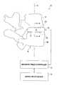
- FIG. 3is a partial sectional, cutaway view of the FIG. 1 prosthesis taken along the section line 3 - 3 shown in FIG. 2 .
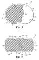
- FIG. 4is a partial diagrammatic, partial cross sectional side view of another type of prosthesis with a magnetic bearing.
- One embodiment of the present applicationis a prosthesis arranged for implantation between two or more bones inside a patient's body.
- the prosthesisincludes opposing magnetic field generating portions that are oriented to provide a repulsive magnetic force there between, that is used for load bearing.
- the magnetic field pattern resulting from the magnetic field generating portionsis adjustable to accommodate different levels of physical activity of a given patient and/or to customize operation of the prosthesis to a given patient.
- FIG. 1depicts prosthesis system 20 of a further embodiment of the present application.
- System 20is partially diagrammatic and is shown in relation to a portion of spine S of a patient along axis A.
- Axis Ais the nominal load bearing axis for spine S when the patient's upper body is upright.
- Spine Sis shown with representative vertebra V 1 and vertebra V 2 .
- System 20includes magnetic field controller 22 in operational communication with operator Input/Output (I/O) device 24 and spinal disk prosthesis 30 .
- Prosthesis 30is positioned between vertebra V 1 and vertebra V 2 in intervertebral cavity C and is configured to provide a magnetic bearing 70 as further described hereinafter.
- the intervertebral space between vertebrae V 1 and V 2(cavity C) is typically formed by removing a diseased and/or injured spinal disk during surgery.
- Prosthesis 30is then implanted in cavity C in a subsequent stage of this surgical procedure.
- FIG. 2is a cross sectional view corresponding to section line 2 - 2 shown in FIG. 1
- FIG. 3is a partial sectional, cutaway view corresponding to section line 3 - 3 shown in FIG. 2
- Prosthesis 30includes end portion 32 a opposite end portion 32 b .
- End portion 32 aincludes load bearing member 34 a defining bearing surface 36 a that is structured to be placed against vertebra V 1 in a mechanical load transmitting or bearing relationship.
- End portion 32 bincludes load bearing member 34 b defining bearing surface 36 b that is structured to be placed against vertebra V 2 in a mechanical load transmitting or bearing relationship.
- End portions 32 a and 32 beach include a respective one of magnets 40 a and 40 b .
- magnets 40 a and 40 bare further designated as corresponding electromagnets 42 a and 42 b .
- Electromagnets 42 a and 42 beach have a corresponding electrically conductive coil 44 a and 44 b of a standard type, which are schematically shown in section.
- Prosthetic linking structure 50interconnects end portions 32 a and 32 b . This interconnection can be by an adhesive, one or more fasteners, or such other joining technique as would occur to those skilled in the art. As illustrated, linking structure 50 is in the form of a flexible fabric sleeve or tube 52 .
- Tube 52can be formed of woven natural fibers and/or synthetic fibers, and can be readily reshaped and reformed by hand. Examples of materials comprising the fabric of the tube 52 include glass, graphite, metal, and/or an organic polymer. Tube 52 defines chamber 54 between end portions 32 a and 32 b . Damping material 60 is positioned in chamber 54 , and is more specifically shown as a resilient polymeric solid 62 . In one form, solid 62 is in the form of one or more types of silicone. It should be appreciated that damping material 60 is not shown in section in FIG. 2 to preserve clarity, but would appear similar to damping material 60 shown in FIG. 4 , which is further described hereinafter.
- load bearing member 34 ais arranged to be placed against one vertebra (vertebra V 1 in FIG. 1 ) and load bearing member 34 b is arranged to be placed against an opposing vertebra (vertebra V 2 in FIG. 1 ).
- magnetic bearing 70is provided by prosthesis 30 , and is configured to maintain a desired nominal degree of spacing between members 34 a and 34 b while within spine S.
- magnetic bearing 70is activated and controlled by magnetic field controller 24 .
- Controller 24is responsive to operator input with device 22 to selectively activate and/or adjust electromagnets 42 a and 42 b .
- Electromagnets 42 a and 42 bare oriented with like magnetic poles P 1 being directed inwardly toward one another in an opposing relationship.
- the opposite poles P 2 of each electromagnetare outwardly directed.
- pole P 1can be of a North (N) or South (S) type with pole P 2 being of the other (opposite) type for each magnet 40 a and 40 b.
- electromagnets 42 a and 42 bFor this orientation with like poles opposing each other, activated electromagnets 42 a and 42 b , and correspondingly end portions 32 a and 32 b , repel one another with repulsive magnetic force R as represented by a double-headed arrow in FIG. 2 .
- the corresponding magnetic fields F 1 and F 2 of electromagnets 42 a and 42 bare represented by partially depicted broken field lines inside chamber 54 . As represented by these field lines, fields F 1 and F 2 repel one another in a standard manner expected for like magnetic poles. Field lines outside chamber 54 have been omitted to preserve clarity.
- magnetic fields F 1 and F 2provide a magnetic field pattern 80 that corresponds to the repulsive magnetic force that is used to bear compressive loading by spine S.
- the repulsive magnetic force Rcauses end portions 32 a and 32 b to remain spaced apart from one another a maximum distance D as defined by linking structure 50 .
- the repulsive magnetic force Rplaces linking structure 50 under tension when no counteracting force is applied. Consequently, linking structure 50 maintains the polar orientation of magnets 40 a and 40 b and correspondingly constrains end portions 32 a and 32 b to maximum distance D.
- prosthesis 30is subjected to loads along axis A through vertebra V 1 and/or V 2 , and is operable to transmit loading from one to the other along axis A.
- damping material 60tends to be compressed and for its particular form as solid 62 , it bulges outward slightly as illustrated in FIG. 2 .
- damping material 60cushions the axial compressive load, complimenting magnetic bearing 70 —particularly with respect to sudden changes in load.
- tube 52 and solid 62also limit movement along a direction orthogonal to axis A, resisting shear loads that could dislocate member 34 a and/or member 34 b relative to axis A.
- magnetic field controller 22remains outside the patient's body, and is only used during or soon after implantation of prosthesis 30 to adjust the magnetic field pattern 80 to a desired load-bearing level, using device 24 to provide adjustment input.
- controller 22can be external or internal and can be used to set the output of an implanted electric power source (not shown) for electromagnets 42 a and 42 b that corresponds to the selected load-bearing level. Once the level is set, controller 22 is no longer needed, and can be removed, such that the magnetic field pattern 80 is maintained by this implanted power source.
- controller 22may be periodically activated by a physician or other health care provider to “fine tune” or otherwise adjust the operation of prosthesis 30 .
- controller 22may be implanted with or without device 24 , and may include an implanted electric power source for electromagnets 42 a and 42 b ; controller 22 , and/or device 24 as needed.
- controller 22 , and optionally device 24are implanted with the patient (user) being able to selectively adjust the magnetic field pattern in accordance with anticipated physical activities or the like.
- An electric power supply for electromagnets 42 a and 42 b , controller 22 , and/or device 24can likewise be implanted for this mode.
- another modeprovides for the reduction or elimination of the magnetic field so that it does not interfere or disrupt other fields for safety reasons or otherwise.
- the nonmagnetic componentsare mechanically configured to provide a desired load support structure when the magnetic field is reduced or absent. This mechanical structure can be aimed at temporary usage or longer term usage as appropriate.
- different control or regulation modesare contemplated as would occur to one skilled in the art.
- Prosthesis 130is arranged to be implanted in an intervertebral space to bear against vertebrae the same as prosthesis 30 .
- prosthesis 130includes opposing end portions 132 a and 132 b that each include a respective load bearing member 134 a and 134 b .
- Load bearing members 134 a and 134 bdefine respective load bearing surfaces 136 a and 136 b .
- End portions 132 a and 132 bare also interconnected by linking structure 50 in the form of fabric tube 52 , which defines chamber 154 .
- Tube 52encloses damping material 60 inside chamber 154 , as previously described in connection with system 20 .
- End portions 132 a and 132 beach include a corresponding magnet 140 a and 140 b .
- magnets 140 a and 140 bare each of a permanent magnet type as further designated by reference numerals 142 a and 142 b , respectively.
- Permanent magnets 142 a and 142 bare oriented with like poles P 1 being directed inward toward one another to create a repulsive magnetic force R as described in connection with prosthesis 30 .
- poles P 2(each opposite pole P 1 ) are outwardly directed away from one another. Similar to prosthesis 30 , the orientation of poles P 1 provides magnetic bearing 170 that may be used in a comparable manner. Likewise, magnetic field pattern 180 results from this polar orientation.
- prosthesis 130can be made so that magnetic field pattern 180 and resulting force R are adjustable. With permanent magnets, such adjustments can be made mechanically by orienting various permanent magnet polar geometries and corresponding shapes relative to one another.
- U.S. Pat. No. 5,595,563 to Moisdondescribes further background regarding such adjustment techniques, which is hereby incorporated by reference in its entirety.
- electromagnetscould be used in combination with permanent magnets to provide adjustability.
- prosthesis 30is implanted between two or more bones other than vertebrae.
- the magnets and corresponding fields and the resultant magnetic field patterncan include both attraction forces from placement of opposite pole types in proximity to one another and repulsion forces from placement of like pole types in proximity to one another.
- “repulsive magnetic force” or “repulsive force”refers to a force resulting from the placement of like magnetic poles in proximity to one another either with or without attractive forces also being present due to opposite magnetic poles being placed in proximity to one another, and further refers to any one of such forces when multiple instances are present.
- U.S. Pat. No. 6,387,096is cited as a source of additional information concerning repulsive forces that are provided together with attractive magnetic forces, which is hereby incorporated by reference.
- one or more of surfaces 36 a , 36 b , 136 a , and 136 bare roughened or otherwise include bone-engaging structures to secure purchase with vertebral surfaces.
- the prosthetic linking structurecan include one or more tethers, cables, braids, wires, cords, bands, filaments, fibers, and/or sheets; a nonfabric tube comprised of an organic polymer, metal, and/or composite; an accordion or bellows tube type that may or may not include a fabric, filamentous, fibrous, and/or woven structure; a combination of these, or such different arrangement as would occur to one skilled in the art.
- the linking structurecan be arranged to present one or more openings between linking structure members or portions, where such openings extend between end portions of the prosthesis.
- a number of spaced apart cordsconnect opposing end portions and define relatively large open spaces lateral to axis A.
- damping material 60can be in the form of a fluid contained in a fluid-tight chamber defined by the linking structure between the opposing end portions and/or can be comprised of a solid other than silicone.
- the linking structureis of a type suitable to retain the fluid, such as a flexible or elastic organic polymer tube structure or a metallic bellows or accordion tube structure.
Landscapes
- Health & Medical Sciences (AREA)
- Biomedical Technology (AREA)
- Engineering & Computer Science (AREA)
- Orthopedic Medicine & Surgery (AREA)
- Neurology (AREA)
- Life Sciences & Earth Sciences (AREA)
- Heart & Thoracic Surgery (AREA)
- Vascular Medicine (AREA)
- Transplantation (AREA)
- Animal Behavior & Ethology (AREA)
- General Health & Medical Sciences (AREA)
- Public Health (AREA)
- Veterinary Medicine (AREA)
- Oral & Maxillofacial Surgery (AREA)
- Cardiology (AREA)
- Prostheses (AREA)
- Materials For Medical Uses (AREA)
Abstract
Description
Claims (20)
Priority Applications (7)
| Application Number | Priority Date | Filing Date | Title |
|---|---|---|---|
| US11/118,277US7811328B2 (en) | 2005-04-29 | 2005-04-29 | System, device and methods for replacing the intervertebral disc with a magnetic or electromagnetic prosthesis |
| PCT/US2006/016484WO2006119124A1 (en) | 2005-04-29 | 2006-05-01 | System, device and methods for replacing the intervertebral disc with a magnetic or electromagnetic prosthesis |
| JP2008509217AJP2008539813A (en) | 2005-04-29 | 2006-05-01 | Artificial organ |
| CA002605861ACA2605861A1 (en) | 2005-04-29 | 2006-05-01 | System, device and methods for replacing the intervertebral disc with a magnetic or electromagnetic prosthesis |
| AU2006242358AAU2006242358A1 (en) | 2005-04-29 | 2006-05-01 | System, device and methods for replacing the intervertebral disc with a magnetic or electromagnetic prosthesis |
| EP06758797AEP1903995A1 (en) | 2005-04-29 | 2006-05-01 | System, device and methods for replacing the intervertebral disc with a magnetic or electromagnetic prosthesis |
| US12/924,009US8211179B2 (en) | 2005-04-29 | 2010-09-17 | System, device and methods for replacing the intervertebral disc with a magnetic or electromagnetic prosthesis |
Applications Claiming Priority (1)
| Application Number | Priority Date | Filing Date | Title |
|---|---|---|---|
| US11/118,277US7811328B2 (en) | 2005-04-29 | 2005-04-29 | System, device and methods for replacing the intervertebral disc with a magnetic or electromagnetic prosthesis |
Related Child Applications (1)
| Application Number | Title | Priority Date | Filing Date |
|---|---|---|---|
| US12/924,009ContinuationUS8211179B2 (en) | 2005-04-29 | 2010-09-17 | System, device and methods for replacing the intervertebral disc with a magnetic or electromagnetic prosthesis |
Publications (2)
| Publication Number | Publication Date |
|---|---|
| US20060247782A1 US20060247782A1 (en) | 2006-11-02 |
| US7811328B2true US7811328B2 (en) | 2010-10-12 |
Family
ID=36829818
Family Applications (2)
| Application Number | Title | Priority Date | Filing Date |
|---|---|---|---|
| US11/118,277Active2028-07-04US7811328B2 (en) | 2005-04-29 | 2005-04-29 | System, device and methods for replacing the intervertebral disc with a magnetic or electromagnetic prosthesis |
| US12/924,009Expired - Fee RelatedUS8211179B2 (en) | 2005-04-29 | 2010-09-17 | System, device and methods for replacing the intervertebral disc with a magnetic or electromagnetic prosthesis |
Family Applications After (1)
| Application Number | Title | Priority Date | Filing Date |
|---|---|---|---|
| US12/924,009Expired - Fee RelatedUS8211179B2 (en) | 2005-04-29 | 2010-09-17 | System, device and methods for replacing the intervertebral disc with a magnetic or electromagnetic prosthesis |
Country Status (6)
| Country | Link |
|---|---|
| US (2) | US7811328B2 (en) |
| EP (1) | EP1903995A1 (en) |
| JP (1) | JP2008539813A (en) |
| AU (1) | AU2006242358A1 (en) |
| CA (1) | CA2605861A1 (en) |
| WO (1) | WO2006119124A1 (en) |
Cited By (44)
| Publication number | Priority date | Publication date | Assignee | Title |
|---|---|---|---|---|
| US20110172768A1 (en)* | 2006-10-19 | 2011-07-14 | Cragg Andrew H | Knee joint prosthesis and hyaluronate compositions for treatment of osteoarthritis |
| US20110257749A1 (en)* | 2010-04-18 | 2011-10-20 | Fleischmann David T | Intervertebral implants having hydromagnetic joints |
| US8795378B2 (en) | 2012-09-27 | 2014-08-05 | Elwha Llc | Artificial joint components including synovial fluid deflecting structures and particle retaining structures |
| US8845741B2 (en) | 2012-09-27 | 2014-09-30 | Seavete LLC | Artificial joint components including integral magnetic fields configured to deflect wear debris particles |
| US8845740B2 (en) | 2012-09-27 | 2014-09-30 | Elwha Llc | Artificial joint components including mechanized synovial fluid deflecting structures and particle retaining structures |
| US9179938B2 (en) | 2013-03-08 | 2015-11-10 | Ellipse Technologies, Inc. | Distraction devices and method of assembling the same |
| US9179960B2 (en) | 2007-10-30 | 2015-11-10 | Ellipse Technologies, Inc. | Skeletal manipulation method |
| US9186183B2 (en) | 2010-08-09 | 2015-11-17 | Ellipse Technologies, Inc. | Maintenance feature in magnetic implant |
| US9192411B2 (en) | 2008-11-10 | 2015-11-24 | Ellipse Technologies, Inc. | External adjustment device for distraction device |
| US9198755B2 (en) | 2008-03-25 | 2015-12-01 | Ellipse Technologies, Inc. | Adjustable implant system |
| US9248043B2 (en) | 2010-06-30 | 2016-02-02 | Ellipse Technologies, Inc. | External adjustment device for distraction device |
| US9271857B2 (en) | 2006-10-20 | 2016-03-01 | Ellipse Technologies, Inc. | Adjustable implant and method of use |
| US9387080B2 (en) | 2012-09-27 | 2016-07-12 | Elwha Llc | Artificial joint components including synovial fluid deflecting structures |
| US9393119B2 (en) | 2011-02-14 | 2016-07-19 | Nuvasive Specialized Orthopedics, Inc. | Variable length device and method |
| US9421046B2 (en) | 2012-10-18 | 2016-08-23 | Nuvasive Specialized Orthopedics, Inc. | Implantable dynamic apparatus having an anti jamming feature |
| US9622792B2 (en) | 2009-04-29 | 2017-04-18 | Nuvasive Specialized Orthopedics, Inc. | Interspinous process device and method |
| US9730612B2 (en) | 2012-06-06 | 2017-08-15 | Nuvasive Specialized Orthopedics, Inc. | Devices and methods for detection of slippage of magnetic coupling in implantable medical devices |
| US9848914B2 (en) | 2009-02-23 | 2017-12-26 | Nuvasive Specialized Orthopedics, Inc. | Non-invasive adjustable distraction system |
| US10016220B2 (en) | 2011-11-01 | 2018-07-10 | Nuvasive Specialized Orthopedics, Inc. | Adjustable magnetic devices and methods of using same |
| US10130405B2 (en) | 2012-10-29 | 2018-11-20 | Nuvasive Specialized Orthopedics, Inc. | Adjustable devices for treating arthritis of the knee |
| US10226242B2 (en) | 2013-07-31 | 2019-03-12 | Nuvasive Specialized Orthopedics, Inc. | Noninvasively adjustable suture anchors |
| US10238427B2 (en) | 2015-02-19 | 2019-03-26 | Nuvasive Specialized Orthopedics, Inc. | Systems and methods for vertebral adjustment |
| US10271885B2 (en) | 2014-12-26 | 2019-04-30 | Nuvasive Specialized Orthopedics, Inc. | Systems and methods for distraction |
| US20190274834A1 (en)* | 2018-03-09 | 2019-09-12 | Stephen Bramblett Johnson | Magnetic prosthetic |
| US10617453B2 (en) | 2015-10-16 | 2020-04-14 | Nuvasive Specialized Orthopedics, Inc. | Adjustable devices for treating arthritis of the knee |
| US10743794B2 (en) | 2011-10-04 | 2020-08-18 | Nuvasive Specialized Orthopedics, Inc. | Devices and methods for non-invasive implant length sensing |
| US10751094B2 (en) | 2013-10-10 | 2020-08-25 | Nuvasive Specialized Orthopedics, Inc. | Adjustable spinal implant |
| US10835290B2 (en) | 2015-12-10 | 2020-11-17 | Nuvasive Specialized Orthopedics, Inc. | External adjustment device for distraction device |
| US10918425B2 (en) | 2016-01-28 | 2021-02-16 | Nuvasive Specialized Orthopedics, Inc. | System and methods for bone transport |
| US11202707B2 (en) | 2008-03-25 | 2021-12-21 | Nuvasive Specialized Orthopedics, Inc. | Adjustable implant system |
| US11207110B2 (en) | 2009-09-04 | 2021-12-28 | Nuvasive Specialized Orthopedics, Inc. | Bone growth device and method |
| US11246694B2 (en) | 2014-04-28 | 2022-02-15 | Nuvasive Specialized Orthopedics, Inc. | System for informational magnetic feedback in adjustable implants |
| US11357549B2 (en) | 2004-07-02 | 2022-06-14 | Nuvasive Specialized Orthopedics, Inc. | Expandable rod system to treat scoliosis and method of using the same |
| US11357547B2 (en) | 2014-10-23 | 2022-06-14 | Nuvasive Specialized Orthopedics Inc. | Remotely adjustable interactive bone reshaping implant |
| US11577097B2 (en) | 2019-02-07 | 2023-02-14 | Nuvasive Specialized Orthopedics, Inc. | Ultrasonic communication in medical devices |
| US11589901B2 (en) | 2019-02-08 | 2023-02-28 | Nuvasive Specialized Orthopedics, Inc. | External adjustment device |
| US11696836B2 (en) | 2013-08-09 | 2023-07-11 | Nuvasive, Inc. | Lordotic expandable interbody implant |
| US11737787B1 (en) | 2021-05-27 | 2023-08-29 | Nuvasive, Inc. | Bone elongating devices and methods of use |
| US11801187B2 (en) | 2016-02-10 | 2023-10-31 | Nuvasive Specialized Orthopedics, Inc. | Systems and methods for controlling multiple surgical variables |
| US11806054B2 (en) | 2021-02-23 | 2023-11-07 | Nuvasive Specialized Orthopedics, Inc. | Adjustable implant, system and methods |
| US11839410B2 (en) | 2012-06-15 | 2023-12-12 | Nuvasive Inc. | Magnetic implants with improved anatomical compatibility |
| US11925389B2 (en) | 2008-10-13 | 2024-03-12 | Nuvasive Specialized Orthopedics, Inc. | Spinal distraction system |
| US12023073B2 (en) | 2021-08-03 | 2024-07-02 | Nuvasive Specialized Orthopedics, Inc. | Adjustable implant |
| US12213708B2 (en) | 2020-09-08 | 2025-02-04 | Nuvasive Specialized Orthopedics, Inc. | Remote control module for adjustable implants |
Families Citing this family (43)
| Publication number | Priority date | Publication date | Assignee | Title |
|---|---|---|---|---|
| US6719765B2 (en) | 2001-12-03 | 2004-04-13 | Bonutti 2003 Trust-A | Magnetic suturing system and method |
| WO2006058221A2 (en) | 2004-11-24 | 2006-06-01 | Abdou Samy M | Devices and methods for inter-vertebral orthopedic device placement |
| US20070233251A1 (en)* | 2006-02-18 | 2007-10-04 | Abdou M S | Use of Magnetic Fields in Orthopedic Implants |
| US9757585B2 (en)* | 2007-06-05 | 2017-09-12 | P Tech, Llc | Magnetic joint implant |
| DE102007053362B4 (en) | 2007-11-06 | 2014-06-05 | Universität Rostock | Magnetically stored artificial joint |
| US8088163B1 (en) | 2008-02-06 | 2012-01-03 | Kleiner Jeffrey B | Tools and methods for spinal fusion |
| US20210378834A1 (en) | 2008-05-22 | 2021-12-09 | Spinal Surgical Strategies, Inc., A Nevada Corporation D/B/A Kleiner Device Labs | Spinal fusion cage system with inserter |
| US20100030337A1 (en)* | 2008-08-04 | 2010-02-04 | Nasser Ani | Spine Surgery Technique And System |
| USD853560S1 (en) | 2008-10-09 | 2019-07-09 | Nuvasive, Inc. | Spinal implant insertion device |
| US8366748B2 (en) | 2008-12-05 | 2013-02-05 | Kleiner Jeffrey | Apparatus and method of spinal implant and fusion |
| USD656610S1 (en) | 2009-02-06 | 2012-03-27 | Kleiner Jeffrey B | Spinal distraction instrument |
| US9247943B1 (en) | 2009-02-06 | 2016-02-02 | Kleiner Intellectual Property, Llc | Devices and methods for preparing an intervertebral workspace |
| US8685031B2 (en) | 2009-09-18 | 2014-04-01 | Spinal Surgical Strategies, Llc | Bone graft delivery system |
| US10973656B2 (en) | 2009-09-18 | 2021-04-13 | Spinal Surgical Strategies, Inc. | Bone graft delivery system and method for using same |
| US20170238984A1 (en) | 2009-09-18 | 2017-08-24 | Spinal Surgical Strategies, Llc | Bone graft delivery device with positioning handle |
| US10245159B1 (en) | 2009-09-18 | 2019-04-02 | Spinal Surgical Strategies, Llc | Bone graft delivery system and method for using same |
| US9629729B2 (en) | 2009-09-18 | 2017-04-25 | Spinal Surgical Strategies, Llc | Biological delivery system with adaptable fusion cage interface |
| USD723682S1 (en) | 2013-05-03 | 2015-03-03 | Spinal Surgical Strategies, Llc | Bone graft delivery tool |
| US9060877B2 (en) | 2009-09-18 | 2015-06-23 | Spinal Surgical Strategies, Llc | Fusion cage with combined biological delivery system |
| US8906028B2 (en) | 2009-09-18 | 2014-12-09 | Spinal Surgical Strategies, Llc | Bone graft delivery device and method of using the same |
| US9186193B2 (en) | 2009-09-18 | 2015-11-17 | Spinal Surgical Strategies, Llc | Fusion cage with combined biological delivery system |
| US9173694B2 (en) | 2009-09-18 | 2015-11-03 | Spinal Surgical Strategies, Llc | Fusion cage with combined biological delivery system |
| USD750249S1 (en) | 2014-10-20 | 2016-02-23 | Spinal Surgical Strategies, Llc | Expandable fusion cage |
| US20110098751A1 (en)* | 2009-10-26 | 2011-04-28 | Nasser Ani | Apparatus for compressing or decompressing a spinal disc and method of use thereof |
| US8764806B2 (en) | 2009-12-07 | 2014-07-01 | Samy Abdou | Devices and methods for minimally invasive spinal stabilization and instrumentation |
| US8454692B2 (en)* | 2010-04-18 | 2013-06-04 | F.I.S.H., Llc | Systems and devices having hydromagnetic joints and hydromagnetic springs |
| AU2011305680B2 (en) | 2010-09-20 | 2014-09-11 | Jeffrey Kleiner | Fusion cage with combined biological delivery system |
| US8845728B1 (en) | 2011-09-23 | 2014-09-30 | Samy Abdou | Spinal fixation devices and methods of use |
| US20130226240A1 (en) | 2012-02-22 | 2013-08-29 | Samy Abdou | Spinous process fixation devices and methods of use |
| CA2879210C (en)* | 2012-07-17 | 2022-07-19 | Stephen D. Cook | Magnetically levitated spinous process implant |
| US10660674B2 (en) | 2012-07-17 | 2020-05-26 | Gomboc, LLC | Magnetically levitated spinous process implants and methods thereof |
| US9198767B2 (en) | 2012-08-28 | 2015-12-01 | Samy Abdou | Devices and methods for spinal stabilization and instrumentation |
| US9320617B2 (en) | 2012-10-22 | 2016-04-26 | Cogent Spine, LLC | Devices and methods for spinal stabilization and instrumentation |
| US9408714B1 (en) | 2015-06-12 | 2016-08-09 | Amendia, Inc. | Artificial disc |
| US10857003B1 (en) | 2015-10-14 | 2020-12-08 | Samy Abdou | Devices and methods for vertebral stabilization |
| USD797290S1 (en) | 2015-10-19 | 2017-09-12 | Spinal Surgical Strategies, Llc | Bone graft delivery tool |
| US10973648B1 (en) | 2016-10-25 | 2021-04-13 | Samy Abdou | Devices and methods for vertebral bone realignment |
| US10744000B1 (en) | 2016-10-25 | 2020-08-18 | Samy Abdou | Devices and methods for vertebral bone realignment |
| EP3357459A1 (en) | 2017-02-03 | 2018-08-08 | Spinal Surgical Strategies, LLC | Bone graft delivery device with positioning handle |
| US11678995B2 (en) | 2018-07-20 | 2023-06-20 | Fellowship Of Orthopaedic Researchers, Inc. | Magnetic intervertebral disc replacement devices and methods thereof |
| US11179248B2 (en) | 2018-10-02 | 2021-11-23 | Samy Abdou | Devices and methods for spinal implantation |
| CN112932750A (en)* | 2021-03-12 | 2021-06-11 | 华中科技大学 | Magnetoelectric interbody fusion cage, interbody fusion cage post-operation position monitoring method and application |
| CN115399925A (en)* | 2022-08-17 | 2022-11-29 | 四川大学华西医院 | Adjustable center of rotation intervertebral disc prosthesis |
Citations (22)
| Publication number | Priority date | Publication date | Assignee | Title |
|---|---|---|---|---|
| US2662228A (en)* | 1951-04-13 | 1953-12-15 | Modern Limb Supply Co Inc | Orthopedic and prosthetic appliance |
| US4024588A (en)* | 1974-10-04 | 1977-05-24 | Allo Pro A.G. | Artificial joints with magnetic attraction or repulsion |
| DE2821678A1 (en) | 1978-05-12 | 1979-11-22 | Sulzer Ag | IMPLANT THAT CAN BE INSERTED BETWEEN NEIGHBORING Vertebrae |
| US5236460A (en)* | 1990-02-12 | 1993-08-17 | Midas Rex Pneumatic Tools, Inc. | Vertebral body prosthesis |
| US5258031A (en)* | 1992-01-06 | 1993-11-02 | Danek Medical | Intervertebral disk arthroplasty |
| US5507835A (en)* | 1994-12-13 | 1996-04-16 | Jore; Matthew B. | Magnetic prosthetic system |
| US5595563A (en)* | 1995-09-05 | 1997-01-21 | Moisdon; Roger G. F. | Method and apparatus for maintaining the position of body parts |
| US5879386A (en)* | 1994-12-13 | 1999-03-09 | Jore; Matthew B. | Magnetic prosthetic system |
| US6110210A (en) | 1999-04-08 | 2000-08-29 | Raymedica, Inc. | Prosthetic spinal disc nucleus having selectively coupled bodies |
| US6292680B1 (en)* | 1997-05-21 | 2001-09-18 | Christopher P. Somogyi | Non-invasive sensing of a physical parameter |
| US20020032484A1 (en)* | 2000-06-13 | 2002-03-14 | Hyde Edward R. | Magnetic array implant and prosthesis |
| US20030014111A1 (en)* | 2001-07-16 | 2003-01-16 | Ralph James D | Interververtebral spacer device having a spiral wave washer force restoring element |
| US20030187510A1 (en)* | 2001-05-04 | 2003-10-02 | Hyde Edward R. | Mobile bearing prostheses |
| US6645248B2 (en)* | 2001-08-24 | 2003-11-11 | Sulzer Orthopedics Ltd. | Artificial intervertebral disc |
| US20030236572A1 (en)* | 2000-10-18 | 2003-12-25 | Morton Bertram | Total joint replacements using magnetism to control instability |
| US20040059423A1 (en)* | 2001-09-28 | 2004-03-25 | Barnes Darryl E. | Implantation of magnets in bone to reduce contact pressure |
| US20040260396A1 (en) | 1999-10-08 | 2004-12-23 | Ferree Bret A. | Artificial disc and joint replacements with modular cushioning components |
| US20050027364A1 (en)* | 2003-08-01 | 2005-02-03 | Kim Daniel H. | Prosthetic intervertebral disc and methods for using the same |
| US6899667B2 (en)* | 2002-10-21 | 2005-05-31 | Paul F. Becker | Method and apparatus for the treatment of physical and mental disorders with low frequency, low flux density magnetic fields |
| US20050234555A1 (en)* | 2004-04-16 | 2005-10-20 | Depuy Spine, Inc. | Intervertebral disc with monitoring and adjusting capabilities |
| US20060069447A1 (en)* | 2004-09-30 | 2006-03-30 | Disilvestro Mark R | Adjustable, remote-controllable orthopaedic prosthesis and associated method |
| US20060079897A1 (en)* | 2004-09-29 | 2006-04-13 | Harrison Michael R | Apparatus and methods for magnetic alteration of anatomical features |
Family Cites Families (5)
| Publication number | Priority date | Publication date | Assignee | Title |
|---|---|---|---|---|
| JPH01249014A (en)* | 1988-03-30 | 1989-10-04 | Masunori Mori | Rocking chair equipped with automatic rocking device and rocking bed for baby |
| JP3276654B2 (en)* | 1992-01-17 | 2002-04-22 | 住友特殊金属株式会社 | Magnetic therapy device |
| EP1542626B1 (en)* | 2002-08-15 | 2012-09-26 | Synthes GmbH | Controlled artificial intervertebral disc implant |
| WO2004057191A1 (en)* | 2002-12-19 | 2004-07-08 | Joma-Hydromechanic Gmbh | Variable volume flow internal gear pump |
| JP2004222832A (en)* | 2003-01-21 | 2004-08-12 | Kanazawa Inst Of Technology | Artificial magnetic joint |
- 2005
- 2005-04-29USUS11/118,277patent/US7811328B2/enactiveActive
- 2006
- 2006-05-01WOPCT/US2006/016484patent/WO2006119124A1/enactiveApplication Filing
- 2006-05-01JPJP2008509217Apatent/JP2008539813A/enactivePending
- 2006-05-01AUAU2006242358Apatent/AU2006242358A1/ennot_activeAbandoned
- 2006-05-01CACA002605861Apatent/CA2605861A1/ennot_activeAbandoned
- 2006-05-01EPEP06758797Apatent/EP1903995A1/ennot_activeWithdrawn
- 2010
- 2010-09-17USUS12/924,009patent/US8211179B2/ennot_activeExpired - Fee Related
Patent Citations (23)
| Publication number | Priority date | Publication date | Assignee | Title |
|---|---|---|---|---|
| US2662228A (en)* | 1951-04-13 | 1953-12-15 | Modern Limb Supply Co Inc | Orthopedic and prosthetic appliance |
| US4024588A (en)* | 1974-10-04 | 1977-05-24 | Allo Pro A.G. | Artificial joints with magnetic attraction or repulsion |
| DE2821678A1 (en) | 1978-05-12 | 1979-11-22 | Sulzer Ag | IMPLANT THAT CAN BE INSERTED BETWEEN NEIGHBORING Vertebrae |
| US5236460A (en)* | 1990-02-12 | 1993-08-17 | Midas Rex Pneumatic Tools, Inc. | Vertebral body prosthesis |
| US5258031A (en)* | 1992-01-06 | 1993-11-02 | Danek Medical | Intervertebral disk arthroplasty |
| US5507835A (en)* | 1994-12-13 | 1996-04-16 | Jore; Matthew B. | Magnetic prosthetic system |
| US5879386A (en)* | 1994-12-13 | 1999-03-09 | Jore; Matthew B. | Magnetic prosthetic system |
| US5595563A (en)* | 1995-09-05 | 1997-01-21 | Moisdon; Roger G. F. | Method and apparatus for maintaining the position of body parts |
| US6292680B1 (en)* | 1997-05-21 | 2001-09-18 | Christopher P. Somogyi | Non-invasive sensing of a physical parameter |
| US6110210A (en) | 1999-04-08 | 2000-08-29 | Raymedica, Inc. | Prosthetic spinal disc nucleus having selectively coupled bodies |
| US20040260396A1 (en) | 1999-10-08 | 2004-12-23 | Ferree Bret A. | Artificial disc and joint replacements with modular cushioning components |
| US20020032484A1 (en)* | 2000-06-13 | 2002-03-14 | Hyde Edward R. | Magnetic array implant and prosthesis |
| US6599321B2 (en)* | 2000-06-13 | 2003-07-29 | Edward R. Hyde, Jr. | Magnetic array implant and prosthesis |
| US20030236572A1 (en)* | 2000-10-18 | 2003-12-25 | Morton Bertram | Total joint replacements using magnetism to control instability |
| US20030187510A1 (en)* | 2001-05-04 | 2003-10-02 | Hyde Edward R. | Mobile bearing prostheses |
| US20030014111A1 (en)* | 2001-07-16 | 2003-01-16 | Ralph James D | Interververtebral spacer device having a spiral wave washer force restoring element |
| US6645248B2 (en)* | 2001-08-24 | 2003-11-11 | Sulzer Orthopedics Ltd. | Artificial intervertebral disc |
| US20040059423A1 (en)* | 2001-09-28 | 2004-03-25 | Barnes Darryl E. | Implantation of magnets in bone to reduce contact pressure |
| US6899667B2 (en)* | 2002-10-21 | 2005-05-31 | Paul F. Becker | Method and apparatus for the treatment of physical and mental disorders with low frequency, low flux density magnetic fields |
| US20050027364A1 (en)* | 2003-08-01 | 2005-02-03 | Kim Daniel H. | Prosthetic intervertebral disc and methods for using the same |
| US20050234555A1 (en)* | 2004-04-16 | 2005-10-20 | Depuy Spine, Inc. | Intervertebral disc with monitoring and adjusting capabilities |
| US20060079897A1 (en)* | 2004-09-29 | 2006-04-13 | Harrison Michael R | Apparatus and methods for magnetic alteration of anatomical features |
| US20060069447A1 (en)* | 2004-09-30 | 2006-03-30 | Disilvestro Mark R | Adjustable, remote-controllable orthopaedic prosthesis and associated method |
Cited By (120)
| Publication number | Priority date | Publication date | Assignee | Title |
|---|---|---|---|---|
| US11357549B2 (en) | 2004-07-02 | 2022-06-14 | Nuvasive Specialized Orthopedics, Inc. | Expandable rod system to treat scoliosis and method of using the same |
| US11712268B2 (en) | 2004-07-02 | 2023-08-01 | Nuvasive Specialized Orthopedics, Inc. | Expandable rod system to treat scoliosis and method of using the same |
| US20110172768A1 (en)* | 2006-10-19 | 2011-07-14 | Cragg Andrew H | Knee joint prosthesis and hyaluronate compositions for treatment of osteoarthritis |
| US8287594B2 (en)* | 2006-10-19 | 2012-10-16 | Intersect Partners, Llc | Knee joint prosthesis and hyaluronate compositions for treatment of osteoarthritis |
| US11672684B2 (en) | 2006-10-20 | 2023-06-13 | Nuvasive Specialized Orthopedics, Inc. | Adjustable implant and method of use |
| US11234849B2 (en) | 2006-10-20 | 2022-02-01 | Nuvasive Specialized Orthopedics, Inc. | Adjustable implant and method of use |
| US10039661B2 (en) | 2006-10-20 | 2018-08-07 | Nuvasive Specialized Orthopedics, Inc. | Adjustable implant and method of use |
| US9271857B2 (en) | 2006-10-20 | 2016-03-01 | Ellipse Technologies, Inc. | Adjustable implant and method of use |
| US9526650B2 (en) | 2006-10-20 | 2016-12-27 | Nuvasive Specialized Orthopedics, Inc. | Adjustable implant and method of use |
| US10349995B2 (en) | 2007-10-30 | 2019-07-16 | Nuvasive Specialized Orthopedics, Inc. | Skeletal manipulation method |
| US11172972B2 (en) | 2007-10-30 | 2021-11-16 | Nuvasive Specialized Orthopedics, Inc. | Skeletal manipulation method |
| US9271781B2 (en) | 2007-10-30 | 2016-03-01 | Ellipse Technologies, Inc. | Skeletal manipulation method |
| US11871974B2 (en) | 2007-10-30 | 2024-01-16 | Nuvasive Specialized Orthopedics, Inc. | Skeletal manipulation method |
| US9179960B2 (en) | 2007-10-30 | 2015-11-10 | Ellipse Technologies, Inc. | Skeletal manipulation method |
| US9693813B2 (en) | 2007-10-30 | 2017-07-04 | Nuvasive Specialized Orthopedics, Inc. | Skeletal manipulation method |
| US9198755B2 (en) | 2008-03-25 | 2015-12-01 | Ellipse Technologies, Inc. | Adjustable implant system |
| US11202707B2 (en) | 2008-03-25 | 2021-12-21 | Nuvasive Specialized Orthopedics, Inc. | Adjustable implant system |
| US10076413B2 (en) | 2008-03-25 | 2018-09-18 | Nuvasive Specialized Orthopedics, Inc. | Adjustable implant system |
| US12076241B2 (en) | 2008-03-25 | 2024-09-03 | Nuvasive Specialized Orthopedics, Inc. | Adjustable implant system |
| US11925389B2 (en) | 2008-10-13 | 2024-03-12 | Nuvasive Specialized Orthopedics, Inc. | Spinal distraction system |
| US9192411B2 (en) | 2008-11-10 | 2015-11-24 | Ellipse Technologies, Inc. | External adjustment device for distraction device |
| US11974782B2 (en) | 2008-11-10 | 2024-05-07 | Nuvasive Specialized Orthopedics, Inc. | External adjustment device for distraction device |
| US10004537B2 (en) | 2008-11-10 | 2018-06-26 | Nuvasive Specialized Orthopedics, Inc. | External adjustment device for distraction device |
| US10729470B2 (en) | 2008-11-10 | 2020-08-04 | Nuvasive Specialized Orthopedics, Inc. | External adjustment device for distraction device |
| US11304729B2 (en) | 2009-02-23 | 2022-04-19 | Nuvasive Specialized Orthhopedics, Inc. | Non-invasive adjustable distraction system |
| US11918254B2 (en) | 2009-02-23 | 2024-03-05 | Nuvasive Specialized Orthopedics Inc. | Adjustable implant system |
| US10517643B2 (en) | 2009-02-23 | 2019-12-31 | Nuvasive Specialized Orthopedics, Inc. | Non-invasive adjustable distraction system |
| US9848914B2 (en) | 2009-02-23 | 2017-12-26 | Nuvasive Specialized Orthopedics, Inc. | Non-invasive adjustable distraction system |
| US11602380B2 (en) | 2009-04-29 | 2023-03-14 | Nuvasive Specialized Orthopedics, Inc. | Interspinous process device and method |
| US9622792B2 (en) | 2009-04-29 | 2017-04-18 | Nuvasive Specialized Orthopedics, Inc. | Interspinous process device and method |
| US10478232B2 (en) | 2009-04-29 | 2019-11-19 | Nuvasive Specialized Orthopedics, Inc. | Interspinous process device and method |
| US11207110B2 (en) | 2009-09-04 | 2021-12-28 | Nuvasive Specialized Orthopedics, Inc. | Bone growth device and method |
| US11944358B2 (en) | 2009-09-04 | 2024-04-02 | Nuvasive Specialized Orthopedics, Inc. | Bone growth device and method |
| US20130261756A1 (en)* | 2010-04-18 | 2013-10-03 | F.I.S.H., Llc | Knee implants having hydromagnetic joints |
| US20110257749A1 (en)* | 2010-04-18 | 2011-10-20 | Fleischmann David T | Intervertebral implants having hydromagnetic joints |
| US9055780B2 (en)* | 2010-04-18 | 2015-06-16 | Roar Labs, Llc | Knee implants having hydromagnetic joints |
| US8449615B2 (en)* | 2010-04-18 | 2013-05-28 | F.I.S.H., Llc | Intervertebral implants having hydromagnetic joints |
| US10660675B2 (en) | 2010-06-30 | 2020-05-26 | Nuvasive Specialized Orthopedics, Inc. | External adjustment device for distraction device |
| US11497530B2 (en) | 2010-06-30 | 2022-11-15 | Nuvasive Specialized Orthopedics, Inc. | External adjustment device for distraction device |
| US12178477B2 (en) | 2010-06-30 | 2024-12-31 | Globus Medical Inc. | External adjustment device for distraction system |
| US9248043B2 (en) | 2010-06-30 | 2016-02-02 | Ellipse Technologies, Inc. | External adjustment device for distraction device |
| US9757159B2 (en) | 2010-08-09 | 2017-09-12 | Nuvasive Specialized Orthopedics, Inc. | Maintenance feature in magnetic implant |
| US9186183B2 (en) | 2010-08-09 | 2015-11-17 | Ellipse Technologies, Inc. | Maintenance feature in magnetic implant |
| US10405891B2 (en) | 2010-08-09 | 2019-09-10 | Nuvasive Specialized Orthopedics, Inc. | Maintenance feature in magnetic implant |
| US11406424B2 (en) | 2010-08-09 | 2022-08-09 | Nuvasive Specialized Orthopedics, Inc. | Maintenance feature in magnetic implant |
| US9393117B2 (en) | 2011-02-14 | 2016-07-19 | Nuvasive Specialized Orthopedics, Inc. | System and method for altering rotational alignment of bone sections |
| US12290290B2 (en) | 2011-02-14 | 2025-05-06 | Nuvasive, Inc. | System and method for altering rotational alignment of bone sections |
| US11406432B2 (en) | 2011-02-14 | 2022-08-09 | Nuvasive Specialized Orthopedics, Inc. | System and method for altering rotational alignment of bone sections |
| US10105167B2 (en) | 2011-02-14 | 2018-10-23 | Nuvasive Specialized Orthopedics, Inc. | System and method for altering rotational alignment of bone sections |
| US9393119B2 (en) | 2011-02-14 | 2016-07-19 | Nuvasive Specialized Orthopedics, Inc. | Variable length device and method |
| US10646262B2 (en) | 2011-02-14 | 2020-05-12 | Nuvasive Specialized Orthopedics, Inc. | System and method for altering rotational alignment of bone sections |
| US10743794B2 (en) | 2011-10-04 | 2020-08-18 | Nuvasive Specialized Orthopedics, Inc. | Devices and methods for non-invasive implant length sensing |
| US11445939B2 (en) | 2011-10-04 | 2022-09-20 | Nuvasive Specialized Orthopedics, Inc. | Devices and methods for non-invasive implant length sensing |
| US10016220B2 (en) | 2011-11-01 | 2018-07-10 | Nuvasive Specialized Orthopedics, Inc. | Adjustable magnetic devices and methods of using same |
| US11123107B2 (en) | 2011-11-01 | 2021-09-21 | Nuvasive Specialized Orthopedics, Inc. | Adjustable magnetic devices and methods of using same |
| US10349982B2 (en) | 2011-11-01 | 2019-07-16 | Nuvasive Specialized Orthopedics, Inc. | Adjustable magnetic devices and methods of using same |
| US11918255B2 (en) | 2011-11-01 | 2024-03-05 | Nuvasive Specialized Orthopedics Inc. | Adjustable magnetic devices and methods of using same |
| US10265101B2 (en) | 2011-11-01 | 2019-04-23 | Nuvasive Specialized Orthopedics, Inc. | Adjustable magnetic devices and methods of using same |
| US9730612B2 (en) | 2012-06-06 | 2017-08-15 | Nuvasive Specialized Orthopedics, Inc. | Devices and methods for detection of slippage of magnetic coupling in implantable medical devices |
| US11839410B2 (en) | 2012-06-15 | 2023-12-12 | Nuvasive Inc. | Magnetic implants with improved anatomical compatibility |
| US8845740B2 (en) | 2012-09-27 | 2014-09-30 | Elwha Llc | Artificial joint components including mechanized synovial fluid deflecting structures and particle retaining structures |
| US8795378B2 (en) | 2012-09-27 | 2014-08-05 | Elwha Llc | Artificial joint components including synovial fluid deflecting structures and particle retaining structures |
| US9387080B2 (en) | 2012-09-27 | 2016-07-12 | Elwha Llc | Artificial joint components including synovial fluid deflecting structures |
| US8845739B2 (en) | 2012-09-27 | 2014-09-30 | Elwha Llc | Artificial joint components including mechanized synovial fluid deflecting structures |
| US9398955B2 (en) | 2012-09-27 | 2016-07-26 | Elwha Llc | Artificial joint components including mechanized synovial fluid deflecting structures and particle retaining structures |
| US9387081B2 (en) | 2012-09-27 | 2016-07-12 | Elwha Llc | Artificial joint components including synovial fluid deflecting structures and particle retaining structures |
| US9398954B2 (en) | 2012-09-27 | 2016-07-26 | Elwha Llc | Artificial joint components including mechanized synovial fluid deflecting structures |
| US8845741B2 (en) | 2012-09-27 | 2014-09-30 | Seavete LLC | Artificial joint components including integral magnetic fields configured to deflect wear debris particles |
| US8828081B2 (en) | 2012-09-27 | 2014-09-09 | Elwha Llc | Artificial joint components including synovial fluid deflecting structures |
| US9421046B2 (en) | 2012-10-18 | 2016-08-23 | Nuvasive Specialized Orthopedics, Inc. | Implantable dynamic apparatus having an anti jamming feature |
| USRE49061E1 (en) | 2012-10-18 | 2022-05-10 | Nuvasive Specialized Orthopedics, Inc. | Intramedullary implants for replacing lost bone |
| USRE49720E1 (en) | 2012-10-18 | 2023-11-07 | Nuvasive Specialized Orthopedics, Inc. | Intramedullary implants for replacing lost bone |
| US9770274B2 (en) | 2012-10-18 | 2017-09-26 | Nuvasive Specialized Orthopedics, Inc. | Intramedullary implants for replacing lost bone |
| US11871971B2 (en) | 2012-10-29 | 2024-01-16 | Nuvasive Specialized Orthopedics, Inc. | Adjustable devices for treating arthritis of the knee |
| US11213330B2 (en) | 2012-10-29 | 2022-01-04 | Nuvasive Specialized Orthopedics, Inc. | Adjustable devices for treating arthritis of the knee |
| US10130405B2 (en) | 2012-10-29 | 2018-11-20 | Nuvasive Specialized Orthopedics, Inc. | Adjustable devices for treating arthritis of the knee |
| US11191579B2 (en) | 2012-10-29 | 2021-12-07 | Nuvasive Specialized Orthopedics, Inc. | Adjustable devices for treating arthritis of the knee |
| US10463406B2 (en) | 2013-03-08 | 2019-11-05 | Nuvasive Specialized Orthopedics, Inc. | Systems and methods for ultrasonic detection of device distraction |
| US11344342B2 (en) | 2013-03-08 | 2022-05-31 | Nuvasive Specialized Orthopedics, Inc. | Systems and methods for ultrasonic detection of device distraction |
| US11857226B2 (en) | 2013-03-08 | 2024-01-02 | Nuvasive Specialized Orthopedics | Systems and methods for ultrasonic detection of device distraction |
| US9179938B2 (en) | 2013-03-08 | 2015-11-10 | Ellipse Technologies, Inc. | Distraction devices and method of assembling the same |
| US11090039B2 (en) | 2013-07-31 | 2021-08-17 | Nuvasive Specialized Orthopedics, Inc. | Noninvasively adjustable suture anchors |
| US10226242B2 (en) | 2013-07-31 | 2019-03-12 | Nuvasive Specialized Orthopedics, Inc. | Noninvasively adjustable suture anchors |
| US11766252B2 (en) | 2013-07-31 | 2023-09-26 | Nuvasive Specialized Orthopedics, Inc. | Noninvasively adjustable suture anchors |
| US12329374B2 (en) | 2013-07-31 | 2025-06-17 | Nuvasive Specialized Orthopedics Inc. | Noninvasively adjustable suture anchors |
| US12213893B2 (en) | 2013-08-09 | 2025-02-04 | Nuvasive, Inc. | Lordotic expandable interbody implant and method of using same |
| US11696836B2 (en) | 2013-08-09 | 2023-07-11 | Nuvasive, Inc. | Lordotic expandable interbody implant |
| US11576702B2 (en) | 2013-10-10 | 2023-02-14 | Nuvasive Specialized Orthopedics, Inc. | Adjustable spinal implant |
| US10751094B2 (en) | 2013-10-10 | 2020-08-25 | Nuvasive Specialized Orthopedics, Inc. | Adjustable spinal implant |
| US11246694B2 (en) | 2014-04-28 | 2022-02-15 | Nuvasive Specialized Orthopedics, Inc. | System for informational magnetic feedback in adjustable implants |
| US11357547B2 (en) | 2014-10-23 | 2022-06-14 | Nuvasive Specialized Orthopedics Inc. | Remotely adjustable interactive bone reshaping implant |
| US12226127B2 (en) | 2014-10-23 | 2025-02-18 | Nuvasive Specialized Orthopedics, Inc. | Remotely adjustable interactive implantable device |
| US11439449B2 (en) | 2014-12-26 | 2022-09-13 | Nuvasive Specialized Orthopedics, Inc. | Systems and methods for distraction |
| US11963705B2 (en) | 2014-12-26 | 2024-04-23 | Nuvasive Specialized Orthopedics, Inc. | Systems and methods for distraction |
| US10271885B2 (en) | 2014-12-26 | 2019-04-30 | Nuvasive Specialized Orthopedics, Inc. | Systems and methods for distraction |
| US11890043B2 (en) | 2014-12-26 | 2024-02-06 | Nuvasive Specialized Orthopedics, Inc. | Systems and methods for distraction |
| US12076051B2 (en) | 2015-02-19 | 2024-09-03 | Nuvasive Specialized Orthopedics, Inc. | Systems and methods for vertebral adjustment |
| US10238427B2 (en) | 2015-02-19 | 2019-03-26 | Nuvasive Specialized Orthopedics, Inc. | Systems and methods for vertebral adjustment |
| US11612416B2 (en) | 2015-02-19 | 2023-03-28 | Nuvasive Specialized Orthopedics, Inc. | Systems and methods for vertebral adjustment |
| US11596456B2 (en) | 2015-10-16 | 2023-03-07 | Nuvasive Specialized Orthopedics, Inc. | Adjustable devices for treating arthritis of the knee |
| US10617453B2 (en) | 2015-10-16 | 2020-04-14 | Nuvasive Specialized Orthopedics, Inc. | Adjustable devices for treating arthritis of the knee |
| US11504162B2 (en) | 2015-12-10 | 2022-11-22 | Nuvasive Specialized Orthopedics, Inc. | External adjustment device for distraction device |
| US10835290B2 (en) | 2015-12-10 | 2020-11-17 | Nuvasive Specialized Orthopedics, Inc. | External adjustment device for distraction device |
| US12185982B2 (en) | 2015-12-10 | 2025-01-07 | Globus Medical Inc. | External adjustment device for distraction device |
| US10918425B2 (en) | 2016-01-28 | 2021-02-16 | Nuvasive Specialized Orthopedics, Inc. | System and methods for bone transport |
| US11801187B2 (en) | 2016-02-10 | 2023-10-31 | Nuvasive Specialized Orthopedics, Inc. | Systems and methods for controlling multiple surgical variables |
| US12263128B2 (en) | 2016-02-10 | 2025-04-01 | Nuvasive Specialized Orthopedics, Inc. | Systems and methods for controlling multiple surgical variables |
| US11617653B2 (en)* | 2018-03-09 | 2023-04-04 | Stephen Bramblett Johnson | Magnetic prosthetic |
| US20190274834A1 (en)* | 2018-03-09 | 2019-09-12 | Stephen Bramblett Johnson | Magnetic prosthetic |
| US10507111B2 (en)* | 2018-03-09 | 2019-12-17 | Stephen Bramblett Johnson | Magnetic prosthetic |
| US12274896B2 (en) | 2019-02-07 | 2025-04-15 | Nuvasive Specialized Orthopedics, Inc. | Ultrasonic communication in medical devices |
| US11577097B2 (en) | 2019-02-07 | 2023-02-14 | Nuvasive Specialized Orthopedics, Inc. | Ultrasonic communication in medical devices |
| US11589901B2 (en) | 2019-02-08 | 2023-02-28 | Nuvasive Specialized Orthopedics, Inc. | External adjustment device |
| US12213708B2 (en) | 2020-09-08 | 2025-02-04 | Nuvasive Specialized Orthopedics, Inc. | Remote control module for adjustable implants |
| US12004784B2 (en) | 2021-02-23 | 2024-06-11 | Nuvasive Specialized Orthopedics, Inc. | Adjustable implant, system and methods |
| US11806054B2 (en) | 2021-02-23 | 2023-11-07 | Nuvasive Specialized Orthopedics, Inc. | Adjustable implant, system and methods |
| US11944359B2 (en) | 2021-02-23 | 2024-04-02 | Nuvasive Specialized Orthopedics, Inc. | Adjustable implant, system and methods |
| US11737787B1 (en) | 2021-05-27 | 2023-08-29 | Nuvasive, Inc. | Bone elongating devices and methods of use |
| US12303169B1 (en) | 2021-05-27 | 2025-05-20 | Nuvasive, Inc. | Bone elongating devices and methods of use |
| US12023073B2 (en) | 2021-08-03 | 2024-07-02 | Nuvasive Specialized Orthopedics, Inc. | Adjustable implant |
Also Published As
| Publication number | Publication date |
|---|---|
| US20060247782A1 (en) | 2006-11-02 |
| JP2008539813A (en) | 2008-11-20 |
| AU2006242358A1 (en) | 2006-11-09 |
| CA2605861A1 (en) | 2006-11-09 |
| US8211179B2 (en) | 2012-07-03 |
| WO2006119124A1 (en) | 2006-11-09 |
| US20110015748A1 (en) | 2011-01-20 |
| EP1903995A1 (en) | 2008-04-02 |
Similar Documents
| Publication | Publication Date | Title |
|---|---|---|
| US7811328B2 (en) | System, device and methods for replacing the intervertebral disc with a magnetic or electromagnetic prosthesis | |
| US7112223B2 (en) | Pseudo arthrosis device | |
| JP2008539813A5 (en) | ||
| JP3256281B2 (en) | Intervertebral stabilization device | |
| JP4303589B2 (en) | Vertebral stabilization assembly | |
| US8226720B2 (en) | Disk augmentation system | |
| CN102341066B (en) | Device for vertebral body distraction and fusion using curved members | |
| JP5916838B2 (en) | Extendable interbody spacer | |
| JP2009544359A (en) | Device for insertion between anatomical structures and its use procedure | |
| US20070156237A1 (en) | Facet joint and spinal ligament replacement | |
| US20080183292A1 (en) | Compliant intervertebral prosthetic devices employing composite elastic and textile structures | |
| US20060167457A1 (en) | Orthopedic fusion plate having both active and passive subsidence controlling features | |
| US8262729B2 (en) | Dynamic ossicular prosthesis | |
| JP2004503289A (en) | Implantation of magnetic array and its prosthesis | |
| US20110015744A1 (en) | Prosthetic spinal disc system | |
| JP2009508633A (en) | Spine stabilization system and method | |
| US7208014B2 (en) | Intervertebral spacer device utilizing a belleville washer having radially extending grooves | |
| CN101006937A (en) | Connecting-rod having external elastic member | |
| WO2006133315A2 (en) | Pseudo arthrosis device | |
| US10835384B2 (en) | Facet joint replacement devices | |
| CN216148283U (en) | Prosthetic device for joint tissue | |
| US20180085227A1 (en) | Total ankle replacement joint | |
| KR101939213B1 (en) | Spinal posterior metallic mesh | |
| JP7720081B2 (en) | Pelvic orthopedic devices | |
| CN109996516A (en) | Magnetic implants for arthrodesis |
Legal Events
| Date | Code | Title | Description |
|---|---|---|---|
| AS | Assignment | Owner name:SDGI HOLDINGS, INC., DELAWARE Free format text:ASSIGNMENT OF ASSIGNORS INTEREST;ASSIGNORS:MOLZ, FRED J., IV;BRUNEAU, AURELIEN;CARLS, THOMAS;AND OTHERS;SIGNING DATES FROM 20050420 TO 20050422;REEL/FRAME:016525/0662 Owner name:SDGI HOLDINGS, INC., DELAWARE Free format text:ASSIGNMENT OF ASSIGNORS INTEREST;ASSIGNORS:MOLZ, FRED J., IV;BRUNEAU, AURELIEN;CARLS, THOMAS;AND OTHERS;REEL/FRAME:016525/0662;SIGNING DATES FROM 20050420 TO 20050422 | |
| AS | Assignment | Owner name:WARSAW ORTHOPEDIC, INC., INDIANA Free format text:MERGER;ASSIGNOR:SDGI HOLDINGS, INC.;REEL/FRAME:020558/0116 Effective date:20060428 Owner name:WARSAW ORTHOPEDIC, INC.,INDIANA Free format text:MERGER;ASSIGNOR:SDGI HOLDINGS, INC.;REEL/FRAME:020558/0116 Effective date:20060428 | |
| STCF | Information on status: patent grant | Free format text:PATENTED CASE | |
| FPAY | Fee payment | Year of fee payment:4 | |
| MAFP | Maintenance fee payment | Free format text:PAYMENT OF MAINTENANCE FEE, 8TH YEAR, LARGE ENTITY (ORIGINAL EVENT CODE: M1552) Year of fee payment:8 | |
| MAFP | Maintenance fee payment | Free format text:PAYMENT OF MAINTENANCE FEE, 12TH YEAR, LARGE ENTITY (ORIGINAL EVENT CODE: M1553); ENTITY STATUS OF PATENT OWNER: LARGE ENTITY Year of fee payment:12 |