US7811320B2 - Intraocular lens system - Google Patents
Intraocular lens systemDownload PDFInfo
- Publication number
- US7811320B2 US7811320B2US12/000,364US36407AUS7811320B2US 7811320 B2US7811320 B2US 7811320B2US 36407 AUS36407 AUS 36407AUS 7811320 B2US7811320 B2US 7811320B2
- Authority
- US
- United States
- Prior art keywords
- lens
- mid
- intraocular
- intraocular lens
- base
- Prior art date
- Legal status (The legal status is an assumption and is not a legal conclusion. Google has not performed a legal analysis and makes no representation as to the accuracy of the status listed.)
- Active, expires
Links
Images


Classifications
- A—HUMAN NECESSITIES
- A61—MEDICAL OR VETERINARY SCIENCE; HYGIENE
- A61F—FILTERS IMPLANTABLE INTO BLOOD VESSELS; PROSTHESES; DEVICES PROVIDING PATENCY TO, OR PREVENTING COLLAPSING OF, TUBULAR STRUCTURES OF THE BODY, e.g. STENTS; ORTHOPAEDIC, NURSING OR CONTRACEPTIVE DEVICES; FOMENTATION; TREATMENT OR PROTECTION OF EYES OR EARS; BANDAGES, DRESSINGS OR ABSORBENT PADS; FIRST-AID KITS
- A61F2/00—Filters implantable into blood vessels; Prostheses, i.e. artificial substitutes or replacements for parts of the body; Appliances for connecting them with the body; Devices providing patency to, or preventing collapsing of, tubular structures of the body, e.g. stents
- A61F2/02—Prostheses implantable into the body
- A61F2/14—Eye parts, e.g. lenses or corneal implants; Artificial eyes
- A61F2/16—Intraocular lenses
- A61F2/1613—Intraocular lenses having special lens configurations, e.g. multipart lenses; having particular optical properties, e.g. pseudo-accommodative lenses, lenses having aberration corrections, diffractive lenses, lenses for variably absorbing electromagnetic radiation, lenses having variable focus
- A61F2/1648—Multipart lenses
- A—HUMAN NECESSITIES
- A61—MEDICAL OR VETERINARY SCIENCE; HYGIENE
- A61F—FILTERS IMPLANTABLE INTO BLOOD VESSELS; PROSTHESES; DEVICES PROVIDING PATENCY TO, OR PREVENTING COLLAPSING OF, TUBULAR STRUCTURES OF THE BODY, e.g. STENTS; ORTHOPAEDIC, NURSING OR CONTRACEPTIVE DEVICES; FOMENTATION; TREATMENT OR PROTECTION OF EYES OR EARS; BANDAGES, DRESSINGS OR ABSORBENT PADS; FIRST-AID KITS
- A61F2/00—Filters implantable into blood vessels; Prostheses, i.e. artificial substitutes or replacements for parts of the body; Appliances for connecting them with the body; Devices providing patency to, or preventing collapsing of, tubular structures of the body, e.g. stents
- A61F2/02—Prostheses implantable into the body
- A61F2/14—Eye parts, e.g. lenses or corneal implants; Artificial eyes
- A61F2/16—Intraocular lenses
- A61F2002/1681—Intraocular lenses having supporting structure for lens, e.g. haptics
- A61F2002/16905—Having means on lens to reduce overall dimension of lens for insertion into small incision
- A61F2002/169051—Segmented zones
- A61F2002/169053—Segments fold
- A—HUMAN NECESSITIES
- A61—MEDICAL OR VETERINARY SCIENCE; HYGIENE
- A61F—FILTERS IMPLANTABLE INTO BLOOD VESSELS; PROSTHESES; DEVICES PROVIDING PATENCY TO, OR PREVENTING COLLAPSING OF, TUBULAR STRUCTURES OF THE BODY, e.g. STENTS; ORTHOPAEDIC, NURSING OR CONTRACEPTIVE DEVICES; FOMENTATION; TREATMENT OR PROTECTION OF EYES OR EARS; BANDAGES, DRESSINGS OR ABSORBENT PADS; FIRST-AID KITS
- A61F2220/00—Fixations or connections for prostheses classified in groups A61F2/00 - A61F2/26 or A61F2/82 or A61F9/00 or A61F11/00 or subgroups thereof
- A61F2220/0025—Connections or couplings between prosthetic parts, e.g. between modular parts; Connecting elements
- A61F2220/0033—Connections or couplings between prosthetic parts, e.g. between modular parts; Connecting elements made by longitudinally pushing a protrusion into a complementary-shaped recess, e.g. held by friction fit
- A—HUMAN NECESSITIES
- A61—MEDICAL OR VETERINARY SCIENCE; HYGIENE
- A61F—FILTERS IMPLANTABLE INTO BLOOD VESSELS; PROSTHESES; DEVICES PROVIDING PATENCY TO, OR PREVENTING COLLAPSING OF, TUBULAR STRUCTURES OF THE BODY, e.g. STENTS; ORTHOPAEDIC, NURSING OR CONTRACEPTIVE DEVICES; FOMENTATION; TREATMENT OR PROTECTION OF EYES OR EARS; BANDAGES, DRESSINGS OR ABSORBENT PADS; FIRST-AID KITS
- A61F2220/00—Fixations or connections for prostheses classified in groups A61F2/00 - A61F2/26 or A61F2/82 or A61F9/00 or A61F11/00 or subgroups thereof
- A61F2220/0025—Connections or couplings between prosthetic parts, e.g. between modular parts; Connecting elements
- A61F2220/005—Connections or couplings between prosthetic parts, e.g. between modular parts; Connecting elements using adhesives
- A—HUMAN NECESSITIES
- A61—MEDICAL OR VETERINARY SCIENCE; HYGIENE
- A61F—FILTERS IMPLANTABLE INTO BLOOD VESSELS; PROSTHESES; DEVICES PROVIDING PATENCY TO, OR PREVENTING COLLAPSING OF, TUBULAR STRUCTURES OF THE BODY, e.g. STENTS; ORTHOPAEDIC, NURSING OR CONTRACEPTIVE DEVICES; FOMENTATION; TREATMENT OR PROTECTION OF EYES OR EARS; BANDAGES, DRESSINGS OR ABSORBENT PADS; FIRST-AID KITS
- A61F2250/00—Special features of prostheses classified in groups A61F2/00 - A61F2/26 or A61F2/82 or A61F9/00 or A61F11/00 or subgroups thereof
- A61F2250/0058—Additional features; Implant or prostheses properties not otherwise provided for
- A61F2250/0059—Additional features; Implant or prostheses properties not otherwise provided for temporary
Definitions
- This inventionrelates to a method for correcting the optical system of an eye using an intraocular lens system. Particularly, this invention relates to a method of correcting focusing abnormalities and optical aberrations measured by wave front or similar technology to quantify optical aberrations in the optical system of the eye, using a laser, or other apparatus and/or methods of fabricating or modifying a lens, for the optical system of an eye having a foldable, interchangeable intraocular lens system provided therein.
- refractive surgeryhas evolved rapidly during the past few decades. Current procedures and methods used by refractive surgeons may not satisfy the total refractive needs of the patient. Particularly, the most commonly performed refractive surgical procedures, such as, for example, cataract extraction with intraocular lens implantation, in addition to the most recently popularized corneal refractive surgical procedures, such as eximer laser photoblation, exhibit limitations. One reason for the limitations is the lack of post-operative refractive accuracy. The lack of post-operative refractive accuracy renders the commonly known refractive surgical procedures uncompetitive with currently available non-surgical alternatives for patients, for example, glasses and contact lenses. Further, because refractive surgery requires local or general anesthesia and incisions into the eye, a need exists for decreasing the trauma resultant from the surgery.
- Presbyopiais a condition which typically affects a large number of people as they age, with the severity of the condition varying depending on the person. Difficulties arise in treating presbyopia because typically once a person manifests symptoms of presbyopia, the symptoms worsen as the person ages. As a person's condition worsens, a different, usually more powerful, lens is required to correct the condition. Conventional techniques for replacing an intraocular lens each time the patient's vision deteriorated do not always present a practical or cost-effective approach. Recent developments in the field, of refractive surgery have made intraocular treatment of presbyopia a feasible course of treatment for those patients that desire or need improved vision, however a need exists for more precise techniques and devices for use in refractive intraocular surgery.
- an adjustable intraocular lenshereinafter referred to as the MC-IOL (multi-component) or C-IOL (compound)
- MC-IOLmulti-component
- C-IOLcompound
- An adjustable IOLallows fine tuning of the initial refractive result by exchanging at least one of the optical elements of the lens implant. As a result, accuracies in the +/ ⁇ 0.25 D range are readily attainable. Furthermore, patients are provided with an opportunity to exchange the “old” lens components with new and hopefully more accurate components. Such an objective is obtainable if the surgeon has an effective, efficient, and safe method of performing lens element exchanges. Additionally, months and/or years after the refractive surgical procedure, if the optical properties of the inserted IOL, for example, the multifocality, become problematic, the surgeon should have the ability to safely exchange the undesirable optical elements of the IOL to correct any optical aberrations that the patient will not or cannot tolerate.
- the inventor of this applicationdeveloped a multi-component intraocular lens, hereinafter referred to as the MC-IOL ( FIG. 1 ), for use following clear lens or refractive cataract surgery, wherein the optical properties of the MC-IOL can be modified at any post-operative time.
- the base intraocular lens component of the MC-IOLis shown in FIG. 1 .
- the mid lensattaches to the top of the base lens and holds the third component of the MC-IOL, the top lens, in place.
- the base intraocular lens 10 and the mid lens 20each have securing flanges 16 , 18 and 20 , 24 , respectively, extending therefrom.
- the MC-IOLalso comprises at least one top lens 30 , as illustrated in FIG. 1 .
- the top lens 30is positioned on top of the mid lens 20 . See FIGS. 1-2 .
- the MC-IOLalso includes projections (or haptics) 11 and 13 which securely hold the MC-IOL in the tissue of the human eye.
- the above-described structurepermits the base intraocular lens 10 to form a platform upon which the mid lens 20 is placed, and to hold the top lens 30 .
- the MC-IOLreplaces the crystalline lens of the human eye. Once a patient's eye has healed after such a surgery, the surgeon reenters the eye and replaces, if necessary, and more than once, the top lens 30 and the mid lens 20 to modify the optical characteristics of the eye until the desired levels for each optical characteristic are attained.
- FIGS. 3A-3Billustrate an assembled compound intraocular lens, hereinafter C-IOL, used with a preexisting lens within the human eye.
- the C-IOLhas two components similar to the mid lens ( FIGS. 4A-4B ) and the top lens ( FIGS. 5A-5B ) components of the MC-IOL.
- FIG. 5Aalso illustrates the axis orientation mark 85 used in some embodiments of MC-IOL lenses, to aid in positioning and orienting the lens.
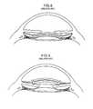
- the preexisting lenscan be the crystalline lens of the eye with the C-IOL placed in the sulcus ( FIG. 6 ) or in the anterior chamber angle ( FIG. 7 ) of the eye's optical system.
- the C-IOLcan also be used with a conventional IOL, as well as with an accommodating IOL, and mounted in the sulcus ( FIG. 8 ), in the anterior chamber angle ( FIG. 9 ), in the anterior chamber with posterior chamber fixation ( FIG. 10 ) or in the anterior chamber with iris fixation ( FIG. 11 ).
- a surgeonmodifies the optical characteristics of the optical system of the eye by using the mid and top lenses in tandem with the preexisting conventional IOL implant or crystalline lens of the eye.
- the C-IOL and MC-IOLprovide numerous enhanced features.
- the C-IOL and MC-IOLcan each be structured as a monofocal or multifocal optical system, correct astigmatism, as well as comprise ultraviolet light-absorbing, tinted, or other such chemically treated materials.
- an adjustable MC-IOL or C-IOLis more desirable than a single component implant.
- MC-IOLmultiple components
- an inventory of about one hundred componentswould be necessary.
- anterior chamber lensesprogressive encapsulation or engulfment of the lens haptics by uveal tissue in the angle often occurs 1-2 years post-operatively. The engulfment typically makes the removal of the lenses and their haptics more difficult.
- Exchange of iris fixated anterior chamber lensesdoes not typically guarantee precise position or orientation. Posterior chamber lenses similarly cannot be removed because of posterior capsule fibrosis. Easy removal and exchangeability is critical for any customized emmetropic system, which can be provided by a specially designed multicomponent lens system.
- a MC-IOL having three elements rather than onepermits refractive customization and adjustability for all refractive errors, as well as for all patients, while using a minimal number of lens elements or parts and requiring little customization on the part of the manufacturer.
- U.S. Pat. No. 5,288,293 to O'Donnell, Jr.discloses a method of modifying a single IOL.
- O'Donnellsuggests that the refractive power of a single IOL may be varied before implantation so that the changes can be made in situ by the ophthalmologist after determining the extent of correction required to improve the vision of the patient before the lens is made.
- the surgical implantation procedureitself may create additional optical aberrations which cannot be anticipated preoperatively and thus the primary lens implant cannot account for these optical aberrations.
- a single component intraocular lenswhich in general is not designed to be removed and with only two optical surfaces, cannot accurately allow for compensation of sphere, cylinder, cylindrical axis, and all forms of optical aberrations that may be discovered after the initial implantation.
- the MC-IOLtypically will have four removable optical surfaces which can compensate for these optical properties.
- the inventor of this applicationinvented the previously discussed MC-IOL and C-IOL that are designed specifically to permit the easy exchange of optical elements at a post-operative period without risk to the human eye or to the patient, beyond the risk of ordinary intraocular surgery.
- the easy exchangeability of optical elementsis critical because the actual surgery of implanting the lens in the first place, as well as variances in the manner in which the eye heals after implantation, potentially create distortions which may not stabilize for several months after the operation. Therefore, the ability to measure and to compensate for the distortion(s) optimally takes place several months after surgery and cannot typically be predicted prior thereto. Since the same surgical wound is used for both the primary and secondary operations, additional distortion due to wound healing would not be anticipated as a result of the second operation.
- the ability to exchange optical elements of a multicomponent or compound intraocular lenscan be economical compared to removing, modifying, and re-implanting a single component lens, as well as easier to perform.
- the MC-IOLhas four surfaces available for modification, two piano and two convex.
- the modificationis made only to the piano surfaces to avoid interfering with the convex side which may already be used for correction of astigmatism (cylinder) or used as a multifocal lens surface.
- cylinderastigmatism
- multifocal lens surfaceThe same preference applies to the CIOL, which has two surfaces available for modification, one piano and the other convex.
- the inventor of this applicationalso developed a system for correcting optical aberrations in the MC-IOL, as described, for example, in U.S. Pat. No. 6,413,276, for conducting measurements to determine any residual or new aberrations present in an operated eye after the biological healing parameters have stabilized, as well as to correct any errors in sphere, cylinder, or cylindrical axis, and for modifying one, two, or more existing lens elements within the implanted optical system based on the conducted measurements.
- the surgical procedure required to implant the intraocular lens componentsrequires a high level of surgeon skill.
- implantation of the removable component of the lensrequires the surgeon to directly visualize the placement of the lens in order to match the notches with the flanges.
- removal of the removable lens componentrequires a special forceps tool for grabbing the base lens, and releasing the tabs holding the sandwich and cap lens together with the base lens (see, for example, the system described in U.S. Pat. No. 5,968,094).
- intraocular lens systemsused a rigid one piece poly methyl methacrylate (PMMA) lens.
- PMMApoly methyl methacrylate
- the PMMA lensis approximately six millimeters in diameter. Because the PMMA lens is rigid, insertion of the PMMA intraocular lens generally requires a seven or eight millimeter incision to be inserted into the eye. In contrast, a flexible or foldable lens can be manipulated and compacted to a much smaller size. Once compacted, the multi-component intraocular lens can be delivered using a relatively smaller incision, for example, about three millimeters or less. By using a smaller incision, the patient reaps optical and practical benefits.
- any time incisions are made to the corneathe cornea loses some of its natural globularity due to imperfections caused by the incisions and the resultant trauma.
- the imperfections in the cornealead to induced astigmatism, or optical aberrations caused by irregularities in the shape of the cornea.
- a surgeonmay also minimize the amount of induced astigmatism. Even though the three-component design simplifies the process of correcting induced astigmatism, minimizing the amount of induced astigmatism remains a primary goal for all intraocular surgeries.
- FIGS. 12-16illustrate the invention disclosed in the '875 patent application.
- FIG. 12Ashows a top or plan view of an intraocular foldable base lens 100 , which is similar to the MC-IOL base lens illustrated in FIG. 3 .
- the base lens 100attaches to the eye by at least one haptic 120 and while the base lens 100 in FIG. 12A can be secured to the eye by at least one haptic, it is preferable that at least two haptics 120 be used.
- each haptic 120extends outward from the base lens 100 , and is tilted from between 10 to 20 degrees, in either direction, relative to a plane taken across the base lens, preferably having a 15 degree positive tilt.
- the base lens 100can also include one or more flanges 105 disposed on and extending outwardly away from the body of the base lens 100 .
- Each flange 105can also have a slot 110 designed or configured to receive or accept an assembly of a top lens 300 and a mid lens 200 therein.
- the base lens in FIG. 13is similar to the base lens 100 ( FIGS. 12A-12B ), except for a groove 130 being defined therein that extends along the entire outer periphery, and a plurality of attachment points 140 , which serve to attach the optical region 150 to the base lens.
- the foldable MC-IOL disclosed in the inventor's '875 applicationincludes two or more additional refractive components, i.e., a top lens 300 and a mid lens 200 .
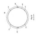
- the mid lens 200which typically allows spherical adjustments, is illustrated in FIGS. 14A-14B , while the top lens 300 ( FIG. 15 ) carries the astigmatic correction and has an orientation projection 305 .
- the mid lens 200may include at least one projection 210 extending away from the body of the mid lens 200 and may have varying lengths depending on the shape and number of projections.
- the mid lens 200also includes a side portion 250 which extends upward, and terminates at a lip 225 , as illustrated in FIG. 14B .
- the side portion 250 and lip 225extend along the outer circumference of the mid lens 200 , thereby defining a notch 230 .
- the top lens 300Prior to insertion into the eye, the top lens 300 engages the notch 225 of the mid lens, such that a seal is formed between the notch 225 and the top lens 300 , and which holds the mid lens 200 and the top lens 300 together as a single assembly.
- the top lens 300is oriented so that, when the top lens 300 is inserted into the mid lens 200 , raised projections or notches 305 of the top lens 300 face the mid lens 200 or may also project away from the mid lens 200 .
- the notches or projections 305can provide directional and axial orientation for the top lens, similar to the axis orientation marks 85 of FIG. 5 .
- the surgeon performing the operation or the lens manufacturerassembles the mid lens 200 and the top lens 300 outside the eye to a predetermined axis orientation to correct the astigmatism, and then inserts the completed assembly into the eye as one folded piece such that the mid lens 200 is sandwiched between the base lens 100 and top lens 300 .
- the surgeoninserts the top lens 300 and the mid lens 200 assembly into the base lens 100 by sliding a projection 210 of the mid lens 200 into a slot 110 of a corresponding flange 105 of the base lens 100 .
- the surgeonadjusts the mid lens 200 and the top lens 300 until the other projection(s) 210 line up with the other slot(s) 105 . Once all projections 210 have been inserted into their corresponding slots 110 , the assembly of the top lens 300 and the mid lens 200 is secured in the base lens 100 , and the procedure is completed.
- the surgeonmay perform a disassembly procedure as discussed herein.
- a cannula containing visco elastic materialwould be introduced into the eye and positioned at the interface between the lens assembly (mid lens 200 and top lens 300 ) and the base lens 100 .
- the injection of visco elasticcauses the mid 200/top 300 lens assembly to elevate, thus disengaging the projections 210 from the slots 110 in the base lens 100 .
- the original lens assemblywould then be removed from the eye, and a new lens assembly placed into the eye and attached to the base lens 100 similar to as described above in the primary operation.
- An embodiment of the present inventionincludes a multi-component intraocular lens, wherein the base lens is attached with haptics, and the top and mid lenses are assembled outside the eye.
- the present inventionprovides a different orientation of the mid lens and top lens than the orientation disclosed in the inventor's '875 application.
- an embodiment of the present inventionincludes inverting or reversing the order of the mid lens and top lens such that the top lens is placed on top of the base lens and the mid lens then positioned on top of the top lens such that the three components are oriented in an order where the base lens is most posterior relative to the patient's eye.
- the top lensis then placed on the base lens and the mid lens arranged on the top lens such that the mid lens is most anterior relative to the patient's eye and the top lens is arranged between or in the middle of the base and mid lens.
- the mid lensincludes a notch with which a projection of the top lens engages to securely maintain the mid/top lens assembly
- an embodiment of the instant applicationprovides the top and mid lenses being joined to each other by a joining means, such as, for example, a medical adhesive that is applied in at least one location where the mid lens interfaces with the top lens.
- the present inventionincludes a feature wherein the haptic of the mid lens has projections extending anteriorly and posteriorly that capture the top lens (circular configuration) and retain the top and mid lens (circular configuration) as an optical assembly.
- the dual direction extending projectionsallow the surgeon or manufacturer the ability to orient the components independently at each of 360° orientations.
- Each of the circular componentsi.e., the mid lens and top lens
- the present inventionincludes an embodiment wherein the mid and top lenses are integrated into a single component such that an adhesive or other such joining mechanism is not necessary to join the mid and top lenses together.
- the front lens or optical assemblycan be custom manufactured into a single piece for each patient to correct sphere cylinder presbyopia, spherical aberrations, and higher order aberrations
- the intraocular lens system of the present inventionallows assembly without the use of special equipment or techniques for securing the top and mid lenses together.
- FIG. 1is a plan view of the base, mid, and top lens components of a currently known multi-component intraocular rigid lens
- FIG. 2is an exploded side view of the assembled base, top, and mid lenses of the currently known multi-component intraocular rigid lens shown in FIG. 1 ;
- FIGS. 3A-3Bare exploded views of a two component compound intraocular lens
- FIGS. 4A-4Bare top and side views, respectively, of a type of compound intraocular lens-top lens component
- FIGS. 5A-5Bare top and side views, respectively, of a type of compound intraocular lens-top lens component
- FIG. 6is a side view of a compound intraocular lens implanted within a human eye ciliary sulcus
- FIG. 7is a side view of another compound intraocular lens implanted within a human eye using the anterior chamber angle as support;
- FIG. 8is a side view of a sulcus mounted compound intraocular lens implanted within a human eye with a previously implanted single component conventional intraocular lens mounted in the capsular bag;
- FIG. 9is a side view of an anterior chamber mounted compound intraocular lens implanted within a human eye with a previously implanted single component conventional intraocular lens mounted in the capsular bag;
- FIG. 10is a side view of an anterior chamber mounted compound intraocular lens on a support secured in the posterior chamber and is implanted within a human eye with a previously implanted single component conventional intraocular lens mounted in the capsular bag;
- FIG. 11is a side view of an iris fixated compound intraocular lens in the anterior chamber that is implanted within a human eye with a previously implanted single component conventional intraocular lens mounted in the capsular bag;
- FIG. 12Ais a top view, with an enlarged side view cutaway, of the base component of a foldable multi-component intraocular lens
- FIG. 12Bis a side view of an enlarged portion of the base lens shown in FIG. 12A ;
- FIG. 13is a top view of the base component of a foldable multi-component intraocular lens
- FIGS. 14A and 14Bare an exploded top view and an exploded side view, respectively, of the mid lens replaceable component of a foldable multi-component intraocular lens;
- FIG. 15is an exploded top view of the top lens component of a foldable multi-component intraocular lens
- FIG. 16is a side view of an optical assembly when the top lens is inserted into the mid lens
- FIGS. 17A-17Care exploded views detailing the assembly process of the flange with the base lens component of a foldable multi-component intraocular lens according to an embodiment of the present invention
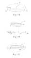
- FIGS. 18A and 18Bare an exploded top view and an exploded side view, respectively, of the top lens replaceable component of a foldable multi-component intraocular lens according to an embodiment of the present invention
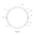
- FIG. 19is an exploded top view of the mid lens component of a foldable multi-component intraocular lens according to an embodiment of the present invention.
- FIG. 20is a side view of an assembly that is formed when the mid lens engages the top lens
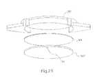
- FIG. 21is an exploded view of an optical assembly according to another embodiment of the present invention.
- FIG. 22is a perspective view of the optical assembly shown in FIG. 21 in the assembled state
- FIG. 23is a perspective view of the optical assembly shown in FIG. 22 assembled with a base lens according to another embodiment of the base lens;
- FIG. 24is a perspective view of an optical assembly according to yet another embodiment of the present invention.
- FIG. 25is a perspective view of the optical assembly shown in FIG. 24 assembled with the base lens shown in FIG. 23
- the fully assembled or end appearance of the base lens 100 ′ of the present invention compared to the base lens 100 described above and illustrated in FIGS. 12A , 12 B and 13is substantially similar to the base lens 100 disclosed in the '875 application. Therefore, a detailed description of many of the common features of the base lens 100 ′ with the base lens 100 is omitted herefrom in order to avoid redundancy.
- the base lens 100 ′ of the present inventiondiffers from the above-described base lens 100 in that the base lens 100 ′ is initially manufactured to be in three components that are to be assembled together and haptics 120 ′ in the base lens 100 ′ are configured to be a plate shape haptic 120 ′ as opposed to the C-loop haptic 120 in the above-described base lens 100 .
- the plate shaped hepatic 120 ′( FIG. 24 ) is configured to have ears 121 ′, 121 ′ which are enveloped and retained by the eye tissues of the patient.
- a notch 101 ′(or cutout or depression) is formed in at least one and preferably two locations of a body of the base lens 100 ′ that diametrically oppose each other across the body of the base lens 100 ′ (only one notch 101 ′ is illustrated).
- a flange 105 ′(or vertical projection) is configured to engage or be inserted into the notch 101 ′.
- the flange 105 ′is previously manufactured to have a slot 110 ′ defined therein.
- the flange 105 ′is snug or snap fit into the notch 101 ′ and can mechanically be held therein to form the base lens 100 ′ ( FIG. 17C ).
- the flange 105 ′to be held in the notch 101 ′ by other conventional and well-known techniques for joining two components of an apparatus, such as, for example only, placing an adhesive or glue in discrete locations along a perimeter of the notch 101 ′ or along the entire perimeter of the notch 101 ′ to join the flange 105 ′ to the base lens 100 ′ at the notch 105 ′, or using a laser to join the flange 105 ′ to the base lens 100 ′, or ultrasonically welding the flange 105 ′ and base lens 100 ′ together, or any other suitable technique that is now known or later developed.
- the slot 110 ′to be formed in the flange 105 ′ by cutting the opening of the slot 110 ′ using a laser.
- the foldable MC-IOL according to the present inventionalso includes two or more additional refractive components, including an assembly of a mid lens 300 ′ and a top lens 200 ′, described more fully herein.
- the top lens 300 and the mid lens 200 of the '875 applicationare similar to the mid lens 300 ′ and top lens 200 ′ described below, with the exception of certain key differences.
- a key difference between the disclosure of the '875 application and the present inventionis the orientation of the top lens 300 and the mid lens 200 .
- the mid lens 200was disposed between the base lens 100 and the top lens 300 .
- the top lens 300is now the mid lens 300 ′ and the mid lens 200 is now the top lens 200 ′.
- top lens 200 ′is illustrated in FIGS. 18A and 18B .
- the top lens 200 ′allows spherical adjustments from ⁇ 4.00 D to +4.00 D in 0.25 D increments.
- the mid lens 300 ′carries the astigmatic correction, which can range, for example, from 0.00 D to 5.00 D cylinder in 0.25 D increments and has an orientation projection 305 .
- the present valuesare presented merely for illustrative purposes, and other possible ranges for the cylinder and the sphere values are considered to be within the scope and pervue of the invention.
- the mid lens 300 ′may be constructed from acrylic, silicone, or any other material suitable for manufacturing a foldable intraocular lens.
- the mid lens 300 ′has a central thickness ranging from 0.1 millimeters to 0.4 millimeters, and a diameter ranging from 1.50 to 8.50 millimeters, but preferably is between 5.50 and 7.00 millimeters.
- the mid lens 300 ′features an optical aperture ranging from 3.0 millimeters to 7.0 millimeters, with a preferable optical aperture of 5.5 millimeters.
- the top lens 200 ′ and/or the mid lens 300 ′may serve multiple purposes depending on the specific embodiment and the specific nature of the problem to be solved.
- the mid lens 300 ′ and/or the top lens 200 ′may correct myopia, presbyopia, astigmatism, spherical aberrations and other higher order aberrations.
- the mid lens 300 ′ and/or the top lens 200 ′may also be used to correct cosmetic defects in the eye.
- the mid lens 300 ′ and/or the top lens 200 ′may also be tinted to protect the eye from ultraviolet rays, or blue light, or to reduce glare, or to change the color of the eye for cosmetic or other purposes.
- the mid lens 300 ′ and/or the top lens 200 ′may also be constructed in a manner which allows the mid lens 300 ′ and/or the top lens 200 ′ to absorb light in the ultraviolet wavelength portion of the light spectrum, for the purpose of achieving the same goals as mentioned above.
- the mid lens 300 ′ and/or the top lens 200 ′may be designed to change the light-gathering aspects of the eye to improve night vision.
- a lens with these characteristicshas potential use for military applications, such as low light or telescopic use, or for underground workers, or in any other application where the patient desires reversibly enhanced night vision, or vision enhancement in a specific area of the spectrum.
- military applicationssuch as low light or telescopic use, or for underground workers, or in any other application where the patient desires reversibly enhanced night vision, or vision enhancement in a specific area of the spectrum.
- athletessuch as baseball players may desire amber-tinted lenses to improve their ability to perform the tasks critical to their sport, such as seeing the ball. Lenses designed for this purpose could be removed when the patient no longer desires the enhanced vision characteristic, for example when the military application is finished, or the athlete's season or career ends.
- the mid lens 300 ′ and/or the top lens 200 ′may be used to deliver pharmacological compounds, such as medicines, into the eye.
- the mid lens 300 ′ and/or the top lens 200 ′ in this embodimentfeature a system for delivering a compound into the eye over a predetermined period of time.
- the surgeonremoves the mid lens 300 ′ and/or the top lens 200 ′, and replaces the mid lens 300 ′ and/or the top lens 200 ′ with a new lens for delivering a compound into the eye, if needed.
- the patientmay conveniently receive delivery of a compound directly into the inner portions of the eye, while minimizing the risk to the patient, and simplifying the delivery of the compound. Because this treatment does not require recurring action by the patient, the treatment avoids the problem of patient non-compliance, which is critically important to the treatment of chronic eye disorders, such as glaucoma, diabetes, and macular degeneration.
- FIG. 18Aillustrates a top view of the top lens 200 ′ of an embodiment of the present invention.
- the top lens 200 ′includes one or more projections 210 extending horizontally from the body of the top lens 200 ′, preferably in the plane parallel to the edge of the top lens 200 ′, but optionally at any angle from 150 to 180 degrees in either direction.
- Each projection 210may extend outward from the lens ranging from 0.5 to 5.0 millimeters from the outer edge of the top lens 200 ′.
- Each projection 210may also have varying lengths depending on the shape and number of projections. The projections 210 are illustrated in FIG.
- any shape which would accomplish the stated purpose of fitting into slot 110 ′ of the flange 105 ′ extending from the base lens 100 ′is considered to be within the scope and pervue of the present invention.
- any shape, indentation, marking, notching, or surface treatment of the flange 105 ′including, for example, ribbing, roughening, adding bumps, notches, and indentations, are considered to be within the scope and pervue of the present invention.
- any adhesive material on the flangefor example, glues, VelcrosTM, cements, resins, pastes, or any other adherent, is also considered to be within the scope and pervue of the present invention.
- the top lens 200 ′also comprises a side portion 250 ′ which extends away from, both anteriorly and posteriory or up and down as viewed in the figure, and along the outer circumference of the top lens 200 ′.
- the top lens 200 ′includes an inner surface 250 a that defines an interface region where the inner surface 250 a of the side portion 250 ′ receives a medical adhesive MA that will securely retain the mid lens 300 ′ thereto in order to define a top lens 200 ′/mid lens 300 ′ assembly.
- the medical adhesive MAPrior to insertion into the eye, the medical adhesive MA is applied to the inner surface 250 a of the top lens 200 ′. It should be noted that the medical adhesive MA may be applied to completely cover the entire surface area of the inner surface 250 a as will be described in further detail below, or less than the entire surface area. The minimum amount of medical adhesive to be applied to the inner surface 250 a should be sufficient to securely retain the mid lens 300 ′ in the top lens 200 ′.
- the medical adhesives MAmay be selected from one of a group including cyanoacrylate adhesives, which may be applied with or without cyanoacrylate accelerators and primers, light cure acrylics, light cure cyanoacrylates, light cure silicones, epoxy adhesives, and any other adhesive that is suitable for the present invention. Although not a requirement, it is preferable that whichever adhesive is selected, that the medical adhesive MA be capable of curing under either UV or visible light sources and respond to low, medium or high intensity light.
- the mid lens 300 ′ of the present inventionincludes a groove 320 defined in a surface of the mid lens 300 ′, and extends along the circumference of the outer periphery of the mid lens 300 ′.
- the groove 320extends along the circumference of the mid lens 300 ′, except for the location of the compression slots 315 , as shown in FIG. 19 . Although four compression slots 315 are illustrated here, embodiments with more compression slots or fewer compression slots are also considered to be within the scope and pervue of the invention. Groove 320 and a series of compression slots 315 allow for an easier engagement of the mid lens 300 ′ with the top lens 200 ′. In other embodiments, the groove 320 could be replaced with other slots or channels defined in the periphery of the lens, and the invention should not be considered to be limited to this specific embodiment.
- the mid lens 300 ′also includes one or more end notches 305 .
- end notches 305are illustrated, but varying numbers of end notches, or no end notches at all, are considered to be within the scope of the invention.
- the end notches 305are raised slightly from the surface of the mid lens 300 ′, and can be configured to be any one of notches, bumps, ridges, or indentations. The notches could also be of various shapes, sizes, and lengths.
- the mid lens 300 ′is oriented so that, when the mid lens 300 ′ engages the top lens 200 ′, the raised projections or notches 305 face the top lens 200 ′ or may also project away from the top lens 200 ′ and toward the base lens 100 .
- the notches or projections 305can provide directional and axial orientation for the mid lens, similar to the axis orientation marks 85 of FIG. 5 .
- the surgeon performing the operation or the lens manufacturerassembles the top lens 200 ′ and the mid lens 300 ′ outside the eye to a predetermined axis orientation to correct the astigmatism, and then inserts the completed assembly into the eye as one folded piece.
- a side view of the completed assembly of the top lens 200 ′ and the mid lens 300 ′is illustrated in FIG. 20 . It should be noted that unlike the assembly shown in FIG.
- the arrangement order of the mid lens 300 ′ and the top lens 200 ′ assembly of the present inventionis reversed such that the mid lens 300 ′, which is the top lens 300 in the '875 application, is not the mid lens 300 ′ of the present invention, wherein the mid lens 200 of the '875 application is the top lens 200 ′, such that the arrangement order of the present invention is base lens 100 , mid lens 300 ′ and top lens 200 ′.
- FIG. 20the sizes have been exaggerated in order to illustrate the relationship between the side surfaces 350 a and 250 a , respectively, of the mid lens 300 ′ and the top lens 200 ′. It is also noted that, although in FIG. 20 , the side surface 350 a of the mid lens 300 ′ is flush with the side surface 250 a of the top lens 200 ′, and the top portion of mid lens 300 ′ is flush with the bottom portion of the top lens 200 ′, this fitting is not required for the assembly of the mid lens 300 ′ and top lens 200 ′. That is, embodiments in which the side surface 350 a of the mid lens 300 ′ is not flush with side surface 250 a of the top lens 200 ′ are considered to be within the scope and pervue of the invention.
- FIG. 21illustrates an exploded view of another embodiment of the present invention wherein the medical adhesive MA is administered along an entire upper surface of the mid lens 300 ′′ and/or an entire lower surface of the top lens 200 ′′ which directly opposes the upper surface of the mid lens 300 ′′.
- the mid lens 300 ′′is provided with at least one projection for engaging the slot 110 ′ formed in the flange 105 ′ of the base lens 100 ′ and, as such, the outer circumferential surface of the top lens 200 ′′ has a constant diameter.
- FIG. 22illustrates an assembled state of the top lens 200 ′′ and the mid lens 300 ′′ with the medical adhesive MA joining the two lenses 200 ′′ and 300 ′′ together into a front lens assembly. As shown in FIG.
- the front assembly( 200 ′′ and 300 ′′) is then assembled with the base lens 100 ′′ which, in this embodiment, has the plate shaped haptic 120 ′, wherein each haptic 120 ′ has at least one pair of the previously discussed dog ears 121 ′, 121 ′.
- the surgeoninserts the mid lens 300 ′ ( 300 ′′) and the top lens 200 ′ ( 200 ′′) assembly into the base lens 100 ′ by sliding a projection 210 into a slot 110 ′ of a corresponding flange 105 ′ of the base lens 100 ′.
- the surgeondoes not need to visually see the individual pieces line up together. Instead, the projection 210 is designed to slide into place with the slot 110 ′.
- the surgeonunfolds the assembly of the mid lens 300 ′ ( 300 ′′) and the top lens 200 ′ ( 200 ′′), and then slides the assembly across the base lens 100 ′ until a first projection 210 lines up with a first slot 110 ′.
- a projection 210lines up with a slot 110 ′
- the projection 210catches in the slot 110 ′, and the surgeon will feel the two pieces lock into place.
- the surgeonadjusts the top lens 200 ′ ( 200 ′′) and the mid lens 300 ′ ( 300 ′′) until the other projection(s) 210 line up with the other slot(s) 105 ′.
- the assembly of the mid lens 300 ′ and the top lens 200 ′is secured in the base lens 100 ′, and the procedure is completed.
- a cannula containing visco elastic materialwould be introduced into the eye and positioned at the interface between the lens assembly (mid lens 300 ′, 300 ′′ and top lens 200 ′, 200 ′′) and the base lens 100 ′.
- the injection of visco elasticcauses the mid lens 300 ′ ( 300 ′′) and top lens 200 ′ ( 200 ′′) assembly to elevate, thus disengaging the projections 210 from the slots 110 ′ in the base lens 100 ′.
- the original lens assemblywould then be removed from the eye, and a new lens assembly placed into the eye and attached to the base lens 100 ′ similar to as described above in the primary operation.
- the top lens 200 ′ ( 200 ′′)may also have additional spherical power ranging from ⁇ 9.50 D to 9.50 D in 0.25 D increments, and may be either monofocal or multifocal.
- the mid lens 300 ′ ( 300 ′′)may also be constructed from acrylic, silicone, or any other material suitable for crafting a foldable intraocular lens.
- the top lens 200 ′ ( 200 ′′)has a plano-convex lens with a central thickness ranging from 0.1 to 0.3 millimeters, and a diameter ranging from 1.5 to 8.5 millimeters, preferably between 6.0 and 6.5 millimeters, and an optical clear aperture ranging from 5.0 to 6.0 millimeters, preferably 5.5 mm.
- the top lens 200 ′may also be manufactured in a manner to allow absorption of light in the ultraviolet wavelength portion of the light spectrum, or other portions of the light spectrum for which it may be clinically important to absorb light, such as the blue light portion.
- the top lens 200 ′ ( 200 ′′)may have at least one bevel 210 formed along an outer edge thereof, allowing the top lens 200 ′ ( 200 ′′) to fit into the opening 110 of the base lens 100 ′.
- the three piece system(i.e. the base lens 100 ′, the mid lens 300 ′ ( 300 ′′), and the top lens 200 ′ ( 200 ′′)) described herein has a spherical power range of ⁇ 20.00 D to +40.00 D and accuracy of +/ ⁇ 0.25 D.
- the three piece systemhas an adjustable cylindrical power of 5.00 D, and adjustable spherical power of +/ ⁇ 9.00 D. Its maximum central thickness is 1.88 millimeters, but could be as thick as 4.0 millimeters.
- the optical element diameterranges from 1.00 millimeters to 8.00 millimeters.
- the optical apertureranges from 3.0 to 7.0 millimeters, with an optimal optical aperture of 5.5 millimeters.
- any of the base, top, and/or mid lens componentsmay be coated with chemicals to decrease their cellular reactivity, such as heparin or other surface passivation techniques to prevent building of cellular debris at the optical interface.
- any of the lens componentsmay be configured with a multifocal corrective component of any of several varieties: derefractive or refractive, bull's eye or aspheric, depending upon the desired optical characteristics.
- extra components beyond the basic base, top, and mid componentsmay be added to help with optical aberrations or other focusing refinements.
- additional top lensesmay be added to the base lens 100 ′, and attached in the same manner as the assembly of the mid lens 300 ′ ( 300 ′′) and the top lens 200 ′ ( 200 ′′) described above.
- a telescopic lenscan be introduced into the lens system for the treatment of macular degeneration. If the base lens 105 illustrated in FIG. 13 is used, then the surgeon can cut the attachment points 140 while the lens is in the eye, and remove the central optic 150 of the base lens 105 . The surgeon can then implant a telescopic assembly, for example a Lipschitz telescopic assembly, in place of the optic portion of the base lens 105 , to allow optical correction for macular degeneration.
- a telescopic assemblyfor example a Lipschitz telescopic assembly
- Optical aberrations and abnormalities present after implantation of the intraocular lensare identified by measuring the optical system using, for example, wave front technology.
- a surface modifiermay be used to modify either a surface of the eye itself, or a component of the intraocular lens system. If a component requires modification or replacement, the surgeon can remove the component, alter the component or replace it with another, and reinsert the component through the same wound which was used to implant the lens. This process is described more fully in U.S. Pat. No. 6,413,276, “Modified Intraocular Lens and Method of Correcting Optical Aberrations Therein,” by the same inventor.
- the mid lens ( 300 ′, 300 ′′) and top lens ( 200 ′, 200 ′′) assemblycan be prefabricated as a singe component or lens 500 that incorporates the two lenses as a single unit.
- the single component or lens 500would preferably be manufactured to the patient's prescription and the lens 500 inserted into the base lens 100 ′ as shown in FIG. 25 . That is, the embodiment shown in FIG. 24 does not require the medical adhesive MA between the mid lens 300 ′, 300 ′′ and the top lens 200 ′, 200 ′′ because the mid and top lenses are integrated together to form the single piece lens 500 .
- the lens assembliesinclude at least one axis orientation mark 185 provided therein that provide the surgeon with assistance in terms of directional and axial orientation of the mid lens 300 ′, 300 ′′ or lens 500 during the insertion procedure.
Landscapes
- Health & Medical Sciences (AREA)
- Ophthalmology & Optometry (AREA)
- Cardiology (AREA)
- Oral & Maxillofacial Surgery (AREA)
- Transplantation (AREA)
- Engineering & Computer Science (AREA)
- Biomedical Technology (AREA)
- Heart & Thoracic Surgery (AREA)
- Vascular Medicine (AREA)
- Life Sciences & Earth Sciences (AREA)
- Animal Behavior & Ethology (AREA)
- General Health & Medical Sciences (AREA)
- Public Health (AREA)
- Veterinary Medicine (AREA)
- Prostheses (AREA)
Abstract
Description
Claims (26)
Priority Applications (8)
| Application Number | Priority Date | Filing Date | Title |
|---|---|---|---|
| US12/000,364US7811320B2 (en) | 2007-01-29 | 2007-12-12 | Intraocular lens system |
| PCT/US2008/001114WO2008094518A1 (en) | 2007-01-29 | 2008-01-29 | Intraocular lens system |
| CA2676408ACA2676408C (en) | 2007-01-29 | 2008-01-29 | Multi-component intraocular lens implanted in an optical system of a human eye |
| ES08724893.6TES2580158T3 (en) | 2007-01-29 | 2008-01-29 | Intraocular lens system |
| EP08724893.6AEP2129331B1 (en) | 2007-01-29 | 2008-01-29 | Intraocular lens system |
| JP2009547324AJP5501767B2 (en) | 2007-01-29 | 2008-01-29 | Intraocular lens system |
| US12/499,613US8066769B2 (en) | 2007-01-29 | 2009-07-08 | Intraocular lens system |
| US12/910,405US9398949B2 (en) | 2007-01-29 | 2010-10-22 | Intraocular lens system |
Applications Claiming Priority (2)
| Application Number | Priority Date | Filing Date | Title |
|---|---|---|---|
| US11/698,875US8066768B2 (en) | 2007-01-29 | 2007-01-29 | Intraocular lens system |
| US12/000,364US7811320B2 (en) | 2007-01-29 | 2007-12-12 | Intraocular lens system |
Related Parent Applications (1)
| Application Number | Title | Priority Date | Filing Date |
|---|---|---|---|
| US11/698,875Continuation-In-PartUS8066768B2 (en) | 2007-01-29 | 2007-01-29 | Intraocular lens system |
Related Child Applications (1)
| Application Number | Title | Priority Date | Filing Date |
|---|---|---|---|
| US12/499,613Continuation-In-PartUS8066769B2 (en) | 2007-01-29 | 2009-07-08 | Intraocular lens system |
Publications (2)
| Publication Number | Publication Date |
|---|---|
| US20080215147A1 US20080215147A1 (en) | 2008-09-04 |
| US7811320B2true US7811320B2 (en) | 2010-10-12 |
Family
ID=39674395
Family Applications (1)
| Application Number | Title | Priority Date | Filing Date |
|---|---|---|---|
| US12/000,364Active2027-04-25US7811320B2 (en) | 2007-01-29 | 2007-12-12 | Intraocular lens system |
Country Status (6)
| Country | Link |
|---|---|
| US (1) | US7811320B2 (en) |
| EP (1) | EP2129331B1 (en) |
| JP (1) | JP5501767B2 (en) |
| CA (1) | CA2676408C (en) |
| ES (1) | ES2580158T3 (en) |
| WO (1) | WO2008094518A1 (en) |
Cited By (25)
| Publication number | Priority date | Publication date | Assignee | Title |
|---|---|---|---|---|
| RU2513958C1 (en)* | 2012-11-09 | 2014-04-20 | федеральное государственное бюджетное учреждение "Межотраслевой научно-технический комплекс "Микрохирургия глаза" имени академика С.Н. Федорова" Министерства здравоохранения Российской Федерации | Artificial implant |
| US9095424B2 (en) | 2012-01-24 | 2015-08-04 | Clarvista Medical, Inc. | Modular intraocular lens designs and methods |
| RU2562360C1 (en)* | 2014-09-24 | 2015-09-10 | Общество с ограниченной ответственностью "НаноВижн" | Intraocular lens design |
| US9195074B2 (en) | 2012-04-05 | 2015-11-24 | Brien Holden Vision Institute | Lenses, devices and methods for ocular refractive error |
| US9201250B2 (en) | 2012-10-17 | 2015-12-01 | Brien Holden Vision Institute | Lenses, devices, methods and systems for refractive error |
| US9220590B2 (en) | 2010-06-10 | 2015-12-29 | Z Lens, Llc | Accommodative intraocular lens and method of improving accommodation |
| US9364316B1 (en) | 2012-01-24 | 2016-06-14 | Clarvista Medical, Inc. | Modular intraocular lens designs, tools and methods |
| US9364318B2 (en) | 2012-05-10 | 2016-06-14 | Z Lens, Llc | Accommodative-disaccommodative intraocular lens |
| US9439754B2 (en) | 2012-02-22 | 2016-09-13 | Omega Opthalmics LLC | Prosthetic capsular bag and method of inserting the same |
| US9504558B2 (en) | 2015-02-10 | 2016-11-29 | Omega Ophthalmics Llc | Attachable optic prosthetic capsular devices |
| US9541773B2 (en) | 2012-10-17 | 2017-01-10 | Brien Holden Vision Institute | Lenses, devices, methods and systems for refractive error |
| US9642699B2 (en) | 2014-06-19 | 2017-05-09 | Omega Ophthalmics Llc | Prosthetic capsular devices, systems, and methods |
| US9993336B2 (en) | 2016-06-06 | 2018-06-12 | Omega Ophthalmics Llc | Prosthetic capsular devices, systems, and methods |
| US10028824B2 (en) | 2012-01-24 | 2018-07-24 | Clarvista Medical, Inc. | Modular intraocular lens designs, tools and methods |
| US10080648B2 (en) | 2012-01-24 | 2018-09-25 | Clarvista Medical, Inc. | Modular intraocular lens designs, tools and methods |
| US10111746B2 (en) | 2016-10-21 | 2018-10-30 | Omega Ophthalmics Llc | Prosthetic capsular devices, systems, and methods |
| RU191715U1 (en)* | 2018-05-07 | 2019-08-19 | Сергей Николаевич Косарев | MODIFICATION OF FIXING ELEMENTS OF THE TELESCOPIC PART OF THE VOLUME-REPLACING INTRAOCULAR LENS |
| US10512535B2 (en) | 2016-08-24 | 2019-12-24 | Z Lens, Llc | Dual mode accommodative-disaccomodative intraocular lens |
| US10603162B2 (en) | 2018-04-06 | 2020-03-31 | Omega Ophthalmics Llc | Prosthetic capsular devices, systems, and methods |
| US11045309B2 (en) | 2016-05-05 | 2021-06-29 | The Regents Of The University Of Colorado | Intraocular lens designs for improved stability |
| US11076948B2 (en) | 2015-11-04 | 2021-08-03 | Alcon Inc. | Modular intraocular lens designs, tools and methods |
| US11364107B2 (en) | 2020-10-12 | 2022-06-21 | Omega Ophthalmics Llc | Prosthetic capsular devices, systems, and methods |
| US11382736B2 (en) | 2017-06-27 | 2022-07-12 | Alcon Inc. | Injector, intraocular lens system, and related methods |
| US11406491B2 (en) | 2015-01-30 | 2022-08-09 | Alcon Inc | Modular intraocular lens designs, tools and methods |
| US11446138B2 (en) | 2014-02-18 | 2022-09-20 | Alcon Inc. | Modular intraocular lens designs, tools and methods |
Families Citing this family (31)
| Publication number | Priority date | Publication date | Assignee | Title |
|---|---|---|---|---|
| US8066769B2 (en)* | 2007-01-29 | 2011-11-29 | Werblin Research & Development Corp. | Intraocular lens system |
| US9398949B2 (en)* | 2007-01-29 | 2016-07-26 | Emmetropia, Inc. | Intraocular lens system |
| JP5591226B2 (en)* | 2008-05-12 | 2014-09-17 | ユニバーシティ・オブ・ユタ・リサーチ・ファウンデイション | Intraocular drug delivery device and related methods |
| EP2177179B1 (en)* | 2008-10-15 | 2011-06-15 | Carl Zeiss Meditec France S.A.S. | Method for modelling an intraocular lens and intraocular lens |
| US9486311B2 (en) | 2013-02-14 | 2016-11-08 | Shifamed Holdings, Llc | Hydrophilic AIOL with bonding |
| JP6838964B2 (en) | 2013-03-21 | 2021-03-03 | シファメド・ホールディングス・エルエルシー | Adjustable intraocular lens |
| US10195018B2 (en) | 2013-03-21 | 2019-02-05 | Shifamed Holdings, Llc | Accommodating intraocular lens |
| KR102287459B1 (en) | 2013-08-20 | 2021-08-09 | 텔레온 홀딩 비.브이. | Intraocular lens assembly |
| DE202013009162U1 (en) | 2013-10-17 | 2013-11-13 | Oculentis Holding B.V. | Intraocular lens assembly |
| CA2959354C (en) | 2014-08-26 | 2018-08-21 | Shifamed Holdings, Llc | Accommodating intraocular lens |
| US10945832B2 (en) | 2014-09-22 | 2021-03-16 | Onpoint Vision, Inc. | Intraocular pseudophakic contact lens with mechanism for securing by anterior leaflet of capsular wall and related system and method |
| US10159562B2 (en) | 2014-09-22 | 2018-12-25 | Kevin J. Cady | Intraocular pseudophakic contact lenses and related systems and methods |
| US11938018B2 (en) | 2014-09-22 | 2024-03-26 | Onpoint Vision, Inc. | Intraocular pseudophakic contact lens (IOPCL) for treating age-related macular degeneration (AMD) or other eye disorders |
| US11109957B2 (en) | 2014-09-22 | 2021-09-07 | Onpoint Vision, Inc. | Intraocular pseudophakic contact lens with mechanism for securing by anterior leaflet of capsular wall and related system and method |
| US10299910B2 (en)* | 2014-09-22 | 2019-05-28 | Kevin J. Cady | Intraocular pseudophakic contact lens with mechanism for securing by anterior leaflet of capsular wall and related system and method |
| ES2651511T3 (en)* | 2015-01-06 | 2018-01-26 | Infinitevision Optics | Multi-component intraocular lens |
| US11141263B2 (en) | 2015-11-18 | 2021-10-12 | Shifamed Holdings, Llc | Multi-piece accommodating intraocular lens |
| JP6934197B2 (en) | 2015-11-18 | 2021-09-15 | シファメド・ホールディングス・エルエルシー | Multiple pieces of adjustable intraocular lens |
| US10350056B2 (en) | 2016-12-23 | 2019-07-16 | Shifamed Holdings, Llc | Multi-piece accommodating intraocular lenses and methods for making and using same |
| CN110446474B (en) | 2016-12-23 | 2021-04-23 | 施菲姆德控股有限责任公司 | Multi-piece accommodating intraocular lens and methods of making and using the same |
| JP7370052B2 (en) | 2017-05-30 | 2023-10-27 | シファメド・ホールディングス・エルエルシー | Surface treatments and related methods and devices for accommodating intraocular lenses |
| AU2018279101B2 (en) | 2017-06-07 | 2023-07-13 | Shifamed Holdings, Llc | Adjustable optical power intraocular lenses |
| US11298262B2 (en) | 2018-07-23 | 2022-04-12 | The Regents Of The University Of Colorado, A Body Corporate | Ophthalmic device for drug delivery |
| US11344406B2 (en)* | 2018-12-20 | 2022-05-31 | Alcon Inc. | Cam-actuated optic lockout mechanism |
| CN110151394A (en)* | 2019-06-19 | 2019-08-23 | 沈阳眼产业技术研究院有限公司 | It is additional to chase after strong type intraocular lens and its application |
| CN110151358A (en)* | 2019-06-19 | 2019-08-23 | 沈阳眼产业技术研究院有限公司 | A kind of double optics portion artificial lens external member and its application |
| TR201922569A2 (en)* | 2019-12-30 | 2021-07-26 | Ondokuz Mayis Ueniversitesi Rektoerluek | Intraocular secondary lens that can be adhered on the intraocular lens in pseudophakic eyes and its application methods. |
| JP2023515280A (en)* | 2020-02-24 | 2023-04-12 | スパイグラス ファーマ インコーポレイテッド | Intraocular drug delivery platform |
| US11399977B2 (en) | 2020-06-04 | 2022-08-02 | SpyGlass Pharma, Inc. | Ophthalmic implant system for drug delivery |
| US11864991B2 (en) | 2020-07-28 | 2024-01-09 | Onpoint Vision, Inc. | Intraocular pseudophakic contact lens (IOPCL)-based telescopic approach for treating age-related macular degeneration (AMD) or other eye disorders |
| US11357620B1 (en) | 2021-09-10 | 2022-06-14 | California LASIK & Eye, Inc. | Exchangeable optics and therapeutics |
Citations (72)
| Publication number | Priority date | Publication date | Assignee | Title |
|---|---|---|---|---|
| US2036379A (en) | 1932-06-06 | 1936-04-07 | Translode Joint Company | Concrete pavement |
| US2039144A (en) | 1934-12-08 | 1936-04-28 | Smith Corp A O | Combination road parting strip and sealing cap |
| US2168925A (en) | 1937-02-25 | 1939-08-08 | Laurence I Hewes | Joint in concrete slabs or pavements |
| DE707212C (en) | 1938-06-28 | 1941-06-16 | Alexander Musall Dipl Ing | Anchorage of the pavement slabs of finished concrete pavement |
| US2354586A (en) | 1940-01-26 | 1944-07-25 | Albert C Fischer | Method of and machine for treating and laying strip material from packages |
| US2798373A (en) | 1953-02-17 | 1957-07-09 | Zelma D Harza | Water stop |
| US2806809A (en) | 1953-08-12 | 1957-09-17 | Charles H Schuh | Art of decorative laminated vinylite panels |
| US3128576A (en) | 1960-11-25 | 1964-04-14 | Detroit Macoid Corp | Waterstop |
| US3194130A (en) | 1961-01-10 | 1965-07-13 | Guntert & Zimmerman Const Div | Apparatus for forming a weakened zone in pavements |
| US3200482A (en) | 1963-02-25 | 1965-08-17 | Brown Co D S | Tool for inserting elastomer highway joint seals and the like |
| US3265556A (en) | 1961-10-20 | 1966-08-09 | Butler Manufacturing Co | Fiber reinforced plastic panel and method of making same |
| US3269282A (en) | 1964-06-11 | 1966-08-30 | Robert L Beesley | Apparatus for providing failure planes in concrete |
| US3458870A (en) | 1964-05-25 | 1969-08-05 | William Stone Jr | Artificial corneal implants having a removable lens member |
| US3945054A (en) | 1973-03-04 | 1976-03-23 | Svyatoslav Nikolaevich Fedorov | Through corneal prosthesis and method of installing same |
| US4010496A (en) | 1975-10-01 | 1977-03-08 | Neefe Charles W | Bifocal lens which positions within the anterior chamber |
| US4240163A (en) | 1979-01-31 | 1980-12-23 | Galin Miles A | Medicament coated intraocular lens |
| US4373218A (en) | 1980-11-17 | 1983-02-15 | Schachar Ronald A | Variable power intraocular lens and method of implanting into the posterior chamber |
| US4402579A (en) | 1981-07-29 | 1983-09-06 | Lynell Medical Technology Inc. | Contact-lens construction |
| DE3428895A1 (en) | 1984-08-04 | 1986-02-13 | Dr. K. Schmidt-Apparatebau, 5205 St Augustin | Intraocular lens |
| US4575373A (en) | 1984-11-02 | 1986-03-11 | Johnson Don R | Laser adjustable intraocular lens and method of altering lens power |
| US4585456A (en) | 1984-03-12 | 1986-04-29 | Ioptex Inc. | Corrective lens for the natural lens of the eye |
| US4585457A (en) | 1985-05-16 | 1986-04-29 | Kalb Irvin M | Inflatable intraocular lens |
| US4636212A (en) | 1982-05-10 | 1987-01-13 | Optical Radiation Corporation | Ultraviolet radiation absorbing intraocular lens |
| US4655770A (en) | 1985-06-06 | 1987-04-07 | Ioptex, Inc. | Surface passivated intraocular lens |
| US4685921A (en) | 1986-02-24 | 1987-08-11 | Peyman Gholam A | Variable refractive power, expandable intraocular lenses |
| US4685922A (en) | 1986-06-25 | 1987-08-11 | Peyman Gholam A | Alterable refractive power intraocular lenses |
| US4731078A (en) | 1985-08-21 | 1988-03-15 | Kingston Technologies Limited Partnership | Intraocular lens |
| EP0269198A1 (en) | 1986-10-20 | 1988-06-01 | Kelman, Charles D. | Intraocular lens with optic of expandable hydrophilic material |
| EP0269197A2 (en) | 1986-11-26 | 1988-06-01 | Industrial Technology Research Institute | Method and means for making pultruded fibre reinforced articles |
| US4769035A (en) | 1987-06-02 | 1988-09-06 | Kelman Charles D | Artificial lens and the method for implanting such lens |
| US4778463A (en) | 1986-07-10 | 1988-10-18 | Jens Hetland | Artificial intraocular lens |
| US4787903A (en) | 1985-07-24 | 1988-11-29 | Grendahl Dennis T | Intraocular lens |
| US4834754A (en) | 1983-07-08 | 1989-05-30 | Shearing Steven P | Intraocular lens |
| US4838266A (en) | 1986-09-08 | 1989-06-13 | Koziol Jeffrey E | Lens shaping device using a laser attenuator |
| US4842601A (en) | 1987-05-18 | 1989-06-27 | Smith S Gregory | Accommodating intraocular lens and method of implanting and using same |
| US4863466A (en) | 1986-04-01 | 1989-09-05 | Schlegel Hans Joachim | Intra-ocular implant lens |
| US4892543A (en) | 1989-02-02 | 1990-01-09 | Turley Dana F | Intraocular lens providing accomodation |
| US4932971A (en) | 1989-06-05 | 1990-06-12 | Kelman Charles D | Clip-on optic assembly |
| US4950289A (en) | 1986-11-03 | 1990-08-21 | Coopervision, Inc. | Small incision intraocular lens with adjustable refractive power |
| WO1991006259A1 (en) | 1988-06-13 | 1991-05-16 | Koziol Jeffrey E | Intraocular lens assembly |
| EP0435528A2 (en) | 1989-12-26 | 1991-07-03 | General Electric Company | X-ray system |
| US5066301A (en) | 1990-10-09 | 1991-11-19 | Wiley Robert G | Variable focus lens |
| US5085013A (en)* | 1990-04-12 | 1992-02-04 | Ascosi Vito S | Contact lens orientation method and apparatus |
| FR2666735A1 (en) | 1990-09-13 | 1992-03-20 | Klw | Intraocular implant with internal cavity |
| US5098444A (en) | 1990-03-16 | 1992-03-24 | Feaster Fred T | Epiphakic intraocular lens and process of implantation |
| US5133748A (en)* | 1990-03-16 | 1992-07-28 | Feaster Fred T | Intraocular lens fixated to the capsular membrane or iris with adhesive |
| WO1992020302A1 (en) | 1991-05-20 | 1992-11-26 | Jan Gerben Frans Worst | Intraocular refractive lens |
| US5171267A (en) | 1989-08-31 | 1992-12-15 | The Board Of Regents Of The University Of Washington | Surface-modified self-passivating intraocular lenses |
| US5196027A (en) | 1990-05-02 | 1993-03-23 | Thompson Keith P | Apparatus and process for application and adjustable reprofiling of synthetic lenticules for vision correction |
| US5222981A (en) | 1991-08-15 | 1993-06-29 | Werblin Research & Development Corp. | Multi-component intraocular lens |
| US5288293A (en) | 1992-09-24 | 1994-02-22 | Donnell Jr Francis E O | In vivo modification of refractive power of an intraocular lens implant |
| US5366502A (en) | 1989-04-28 | 1994-11-22 | Nestle S.A. | Supplementary intraocular lens system |
| EP0435525B1 (en) | 1989-12-27 | 1995-03-08 | Nestle S.A. | Multifocal diffractive ophthalmic lens and method of manufacture |
| US5628798A (en)* | 1996-03-18 | 1997-05-13 | Harry C. Eggleston | Adjustable and removable intraocular lens implant |
| US5728155A (en) | 1996-01-22 | 1998-03-17 | Quantum Solutions, Inc. | Adjustable intraocular lens |
| US5777719A (en) | 1996-12-23 | 1998-07-07 | University Of Rochester | Method and apparatus for improving vision and the resolution of retinal images |
| US5892617A (en) | 1997-07-28 | 1999-04-06 | Wallace; Robert E. | Multi-function day/night observation, ranging, and sighting device and method of its operation |
| US5943117A (en) | 1996-11-22 | 1999-08-24 | Jozef F. Van de Velde | Scanning laser ophthalmoscope for retinal microphotocoagulation and measurement of wavefront aberrations |
| US5968094A (en)* | 1995-09-18 | 1999-10-19 | Emmetropia, Inc. | Compound intraocular lens |
| US6113633A (en)* | 1996-01-26 | 2000-09-05 | Allergan | Primary and supplemental intraocular lens system |
| US6254637B1 (en)* | 2000-04-10 | 2001-07-03 | Lucid Korea Co., Ltd. | Artificial cornea and implantation thereof |
| US6255338B1 (en) | 1995-05-19 | 2001-07-03 | The University Of East Anglia | Use of calcium intracellular store inactivators and formulations thereof as cell growth inhibitors |
| US6413276B1 (en) | 2000-04-26 | 2002-07-02 | Emmetropia, Inc. | Modified intraocular lens and method of correcting optical aberrations therein |
| US6524340B2 (en) | 2001-05-23 | 2003-02-25 | Henry M. Israel | Accommodating intraocular lens assembly |
| US6551354B1 (en) | 2000-03-09 | 2003-04-22 | Advanced Medical Optics, Inc. | Accommodating intraocular lens |
| US20030204254A1 (en) | 2002-04-29 | 2003-10-30 | Qun Peng | Accommodative intraocular lens |
| US20050125058A1 (en) | 2003-12-03 | 2005-06-09 | Eyeonics, Inc. | Accommodating hybrid intraocular lens |
| US6991651B2 (en)* | 2002-11-27 | 2006-01-31 | Valdemar Portney | Adjustable intraocular lens system and intraocular lenses therefor |
| US20060047339A1 (en)* | 2004-08-27 | 2006-03-02 | Brown David C | Intracapsular pseudophakic device |
| US7008449B2 (en) | 2001-01-30 | 2006-03-07 | Willis Timothy R | Refractive intraocular implant lens and method |
| US7097660B2 (en) | 2001-12-10 | 2006-08-29 | Valdemar Portney | Accommodating intraocular lens |
| US7300464B2 (en)* | 2004-09-30 | 2007-11-27 | Alcon, Inc. | Intraocular lens |
Family Cites Families (3)
| Publication number | Priority date | Publication date | Assignee | Title |
|---|---|---|---|---|
| US20060206206A1 (en)* | 2003-06-06 | 2006-09-14 | Peyman Gholam A | Intraocular telescope |
| US7223288B2 (en) | 2003-05-21 | 2007-05-29 | Alcon, Inc. | Accommodative intraocular lens |
| US20070010881A1 (en)* | 2005-07-11 | 2007-01-11 | Alcon, Inc. | Intraocular lens system |
- 2007
- 2007-12-12USUS12/000,364patent/US7811320B2/enactiveActive
- 2008
- 2008-01-29CACA2676408Apatent/CA2676408C/enactiveActive
- 2008-01-29JPJP2009547324Apatent/JP5501767B2/enactiveActive
- 2008-01-29ESES08724893.6Tpatent/ES2580158T3/enactiveActive
- 2008-01-29WOPCT/US2008/001114patent/WO2008094518A1/enactiveApplication Filing
- 2008-01-29EPEP08724893.6Apatent/EP2129331B1/enactiveActive
Patent Citations (73)
| Publication number | Priority date | Publication date | Assignee | Title |
|---|---|---|---|---|
| US2036379A (en) | 1932-06-06 | 1936-04-07 | Translode Joint Company | Concrete pavement |
| US2039144A (en) | 1934-12-08 | 1936-04-28 | Smith Corp A O | Combination road parting strip and sealing cap |
| US2168925A (en) | 1937-02-25 | 1939-08-08 | Laurence I Hewes | Joint in concrete slabs or pavements |
| DE707212C (en) | 1938-06-28 | 1941-06-16 | Alexander Musall Dipl Ing | Anchorage of the pavement slabs of finished concrete pavement |
| US2354586A (en) | 1940-01-26 | 1944-07-25 | Albert C Fischer | Method of and machine for treating and laying strip material from packages |
| US2798373A (en) | 1953-02-17 | 1957-07-09 | Zelma D Harza | Water stop |
| US2806809A (en) | 1953-08-12 | 1957-09-17 | Charles H Schuh | Art of decorative laminated vinylite panels |
| US3128576A (en) | 1960-11-25 | 1964-04-14 | Detroit Macoid Corp | Waterstop |
| US3194130A (en) | 1961-01-10 | 1965-07-13 | Guntert & Zimmerman Const Div | Apparatus for forming a weakened zone in pavements |
| US3265556A (en) | 1961-10-20 | 1966-08-09 | Butler Manufacturing Co | Fiber reinforced plastic panel and method of making same |
| US3200482A (en) | 1963-02-25 | 1965-08-17 | Brown Co D S | Tool for inserting elastomer highway joint seals and the like |
| US3458870A (en) | 1964-05-25 | 1969-08-05 | William Stone Jr | Artificial corneal implants having a removable lens member |
| US3269282A (en) | 1964-06-11 | 1966-08-30 | Robert L Beesley | Apparatus for providing failure planes in concrete |
| US3945054A (en) | 1973-03-04 | 1976-03-23 | Svyatoslav Nikolaevich Fedorov | Through corneal prosthesis and method of installing same |
| US4010496A (en) | 1975-10-01 | 1977-03-08 | Neefe Charles W | Bifocal lens which positions within the anterior chamber |
| US4240163A (en) | 1979-01-31 | 1980-12-23 | Galin Miles A | Medicament coated intraocular lens |
| US4373218A (en) | 1980-11-17 | 1983-02-15 | Schachar Ronald A | Variable power intraocular lens and method of implanting into the posterior chamber |
| US4402579A (en) | 1981-07-29 | 1983-09-06 | Lynell Medical Technology Inc. | Contact-lens construction |
| US4636212A (en) | 1982-05-10 | 1987-01-13 | Optical Radiation Corporation | Ultraviolet radiation absorbing intraocular lens |
| US4834754A (en) | 1983-07-08 | 1989-05-30 | Shearing Steven P | Intraocular lens |
| US4585456A (en) | 1984-03-12 | 1986-04-29 | Ioptex Inc. | Corrective lens for the natural lens of the eye |
| DE3428895A1 (en) | 1984-08-04 | 1986-02-13 | Dr. K. Schmidt-Apparatebau, 5205 St Augustin | Intraocular lens |
| US4575373A (en) | 1984-11-02 | 1986-03-11 | Johnson Don R | Laser adjustable intraocular lens and method of altering lens power |
| US4585457A (en) | 1985-05-16 | 1986-04-29 | Kalb Irvin M | Inflatable intraocular lens |
| US4655770A (en) | 1985-06-06 | 1987-04-07 | Ioptex, Inc. | Surface passivated intraocular lens |
| US4787903A (en) | 1985-07-24 | 1988-11-29 | Grendahl Dennis T | Intraocular lens |
| US4731078A (en) | 1985-08-21 | 1988-03-15 | Kingston Technologies Limited Partnership | Intraocular lens |
| US4685921A (en) | 1986-02-24 | 1987-08-11 | Peyman Gholam A | Variable refractive power, expandable intraocular lenses |
| US4863466A (en) | 1986-04-01 | 1989-09-05 | Schlegel Hans Joachim | Intra-ocular implant lens |
| US4685922A (en) | 1986-06-25 | 1987-08-11 | Peyman Gholam A | Alterable refractive power intraocular lenses |
| US4778463A (en) | 1986-07-10 | 1988-10-18 | Jens Hetland | Artificial intraocular lens |
| US4838266A (en) | 1986-09-08 | 1989-06-13 | Koziol Jeffrey E | Lens shaping device using a laser attenuator |
| EP0269198A1 (en) | 1986-10-20 | 1988-06-01 | Kelman, Charles D. | Intraocular lens with optic of expandable hydrophilic material |
| US4950289A (en) | 1986-11-03 | 1990-08-21 | Coopervision, Inc. | Small incision intraocular lens with adjustable refractive power |
| EP0269197A2 (en) | 1986-11-26 | 1988-06-01 | Industrial Technology Research Institute | Method and means for making pultruded fibre reinforced articles |
| US4842601A (en) | 1987-05-18 | 1989-06-27 | Smith S Gregory | Accommodating intraocular lens and method of implanting and using same |
| US4769035A (en) | 1987-06-02 | 1988-09-06 | Kelman Charles D | Artificial lens and the method for implanting such lens |
| WO1991006259A1 (en) | 1988-06-13 | 1991-05-16 | Koziol Jeffrey E | Intraocular lens assembly |
| US4892543A (en) | 1989-02-02 | 1990-01-09 | Turley Dana F | Intraocular lens providing accomodation |
| US5366502A (en) | 1989-04-28 | 1994-11-22 | Nestle S.A. | Supplementary intraocular lens system |
| US4932971A (en) | 1989-06-05 | 1990-06-12 | Kelman Charles D | Clip-on optic assembly |
| US5171267A (en) | 1989-08-31 | 1992-12-15 | The Board Of Regents Of The University Of Washington | Surface-modified self-passivating intraocular lenses |
| EP0435528A2 (en) | 1989-12-26 | 1991-07-03 | General Electric Company | X-ray system |
| EP0435525B1 (en) | 1989-12-27 | 1995-03-08 | Nestle S.A. | Multifocal diffractive ophthalmic lens and method of manufacture |
| US5098444A (en) | 1990-03-16 | 1992-03-24 | Feaster Fred T | Epiphakic intraocular lens and process of implantation |
| US5133748A (en)* | 1990-03-16 | 1992-07-28 | Feaster Fred T | Intraocular lens fixated to the capsular membrane or iris with adhesive |
| US5085013A (en)* | 1990-04-12 | 1992-02-04 | Ascosi Vito S | Contact lens orientation method and apparatus |
| US5196027A (en) | 1990-05-02 | 1993-03-23 | Thompson Keith P | Apparatus and process for application and adjustable reprofiling of synthetic lenticules for vision correction |
| FR2666735A1 (en) | 1990-09-13 | 1992-03-20 | Klw | Intraocular implant with internal cavity |
| US5066301A (en) | 1990-10-09 | 1991-11-19 | Wiley Robert G | Variable focus lens |
| WO1992020302A1 (en) | 1991-05-20 | 1992-11-26 | Jan Gerben Frans Worst | Intraocular refractive lens |
| US5222981A (en) | 1991-08-15 | 1993-06-29 | Werblin Research & Development Corp. | Multi-component intraocular lens |
| US5288293A (en) | 1992-09-24 | 1994-02-22 | Donnell Jr Francis E O | In vivo modification of refractive power of an intraocular lens implant |
| US6255338B1 (en) | 1995-05-19 | 2001-07-03 | The University Of East Anglia | Use of calcium intracellular store inactivators and formulations thereof as cell growth inhibitors |
| US5968094A (en)* | 1995-09-18 | 1999-10-19 | Emmetropia, Inc. | Compound intraocular lens |
| US5728155A (en) | 1996-01-22 | 1998-03-17 | Quantum Solutions, Inc. | Adjustable intraocular lens |
| US20020161436A1 (en)* | 1996-01-26 | 2002-10-31 | Allergan | Primary and supplemental intraocular lens system |
| US6113633A (en)* | 1996-01-26 | 2000-09-05 | Allergan | Primary and supplemental intraocular lens system |
| US5628798A (en)* | 1996-03-18 | 1997-05-13 | Harry C. Eggleston | Adjustable and removable intraocular lens implant |
| US5943117A (en) | 1996-11-22 | 1999-08-24 | Jozef F. Van de Velde | Scanning laser ophthalmoscope for retinal microphotocoagulation and measurement of wavefront aberrations |
| US5777719A (en) | 1996-12-23 | 1998-07-07 | University Of Rochester | Method and apparatus for improving vision and the resolution of retinal images |
| US5892617A (en) | 1997-07-28 | 1999-04-06 | Wallace; Robert E. | Multi-function day/night observation, ranging, and sighting device and method of its operation |
| US6551354B1 (en) | 2000-03-09 | 2003-04-22 | Advanced Medical Optics, Inc. | Accommodating intraocular lens |
| US6254637B1 (en)* | 2000-04-10 | 2001-07-03 | Lucid Korea Co., Ltd. | Artificial cornea and implantation thereof |
| US6413276B1 (en) | 2000-04-26 | 2002-07-02 | Emmetropia, Inc. | Modified intraocular lens and method of correcting optical aberrations therein |
| US7008449B2 (en) | 2001-01-30 | 2006-03-07 | Willis Timothy R | Refractive intraocular implant lens and method |
| US6524340B2 (en) | 2001-05-23 | 2003-02-25 | Henry M. Israel | Accommodating intraocular lens assembly |
| US7097660B2 (en) | 2001-12-10 | 2006-08-29 | Valdemar Portney | Accommodating intraocular lens |
| US20030204254A1 (en) | 2002-04-29 | 2003-10-30 | Qun Peng | Accommodative intraocular lens |
| US6991651B2 (en)* | 2002-11-27 | 2006-01-31 | Valdemar Portney | Adjustable intraocular lens system and intraocular lenses therefor |
| US20050125058A1 (en) | 2003-12-03 | 2005-06-09 | Eyeonics, Inc. | Accommodating hybrid intraocular lens |
| US20060047339A1 (en)* | 2004-08-27 | 2006-03-02 | Brown David C | Intracapsular pseudophakic device |
| US7300464B2 (en)* | 2004-09-30 | 2007-11-27 | Alcon, Inc. | Intraocular lens |
Non-Patent Citations (11)
| Title |
|---|
| Binder et al. "Hydrogel Refractive Keratoplasty. Lens Removal and Exchanges" vol. 2, Cornea at pp. 119-125. |
| Cyw Khng, et al., "The IOL flip: rescue for foldable lens implantation gone wrong", BJO Online Journals, Br. J. Ophthalmol 2003;87;656-657 doi:10.1136/bjo.87.5.656. |
| Cyw Khng, et al., "The IOL flip: rescue for foldable lens implantation gone wrong", The BMJ Interview-BJO Online Journals, Oct. 30, 2006, pp. 1-5. |
| Ernani Serpa Junior, et al., "Comparison of PMMA, foldable silicone and foldable acrylic hydrophobic intraocular lenses in combined phacoemulsification and trabeculectomy", Arq Bras Oftalmol. 2005; 68 (1):29-35. |
| Theodore P. Werblin, "Why Should Refractive Surgeons Be Looking Beyond the Corenea?", Barraquer Lecture 1998, Journal of Refractive Surgery vol. 15 May/Jun. 1999, pp. 359-376. |
| Werblin "Lamellar Refractive Surgery: Where Have We Been and Where are we going?" vol. 5, No. 3, Refractive and Corneal Surgery, pp. 167-176 (Jan. 1989). |
| Werblin et al., "Epikeratophakia: The surgical correction of aphakia. III. Preliminary results of a prospective clinical trial," 93 Arch. Opth., pp. 342-347 (1982). |
| Werblin et al., "Hydrogel Keratophakia: Measurement of Intraocular Pressure," vol. 11, No. 4 CLAO Journal, pp. 354-357 (Oct. 1985). |
| Werblin et al., "Refractive Corneal Surgery: The Use of Implantable Alloplastic Lens Material," 11 Austrial Journal of Opthalmology, pp. 325-331 (1983). |
| Werblin et al., Epikeratophakia: The surgical correction of aphakia. II. Preliminary results in a non-human primate model; 1(3) Curr. Eye Res., pp. 131-137; 1981. |
| Wikipedia, "Presbyopia", The Free Encyclopedia, pp. 1-4, Oct. 30, 2006. |
Cited By (86)
| Publication number | Priority date | Publication date | Assignee | Title |
|---|---|---|---|---|
| US9220590B2 (en) | 2010-06-10 | 2015-12-29 | Z Lens, Llc | Accommodative intraocular lens and method of improving accommodation |
| US10524900B2 (en) | 2010-06-10 | 2020-01-07 | Z Lens, Llc | Accommodative intraocular lens and method of improving accommodation |
| US9681946B2 (en) | 2012-01-24 | 2017-06-20 | Clarvista Medical, Inc. | Modular intraocular lens designs and methods |
| US9125736B2 (en) | 2012-01-24 | 2015-09-08 | Clarvista Medical, Inc. | Modular intraocular lens designs and methods |
| US10080648B2 (en) | 2012-01-24 | 2018-09-25 | Clarvista Medical, Inc. | Modular intraocular lens designs, tools and methods |
| US10028824B2 (en) | 2012-01-24 | 2018-07-24 | Clarvista Medical, Inc. | Modular intraocular lens designs, tools and methods |
| US9364316B1 (en) | 2012-01-24 | 2016-06-14 | Clarvista Medical, Inc. | Modular intraocular lens designs, tools and methods |
| US11406490B2 (en) | 2012-01-24 | 2022-08-09 | Alcon Inc. | Modular intraocular lens designs and methods |
| US9095424B2 (en) | 2012-01-24 | 2015-08-04 | Clarvista Medical, Inc. | Modular intraocular lens designs and methods |
| US9877825B2 (en) | 2012-01-24 | 2018-01-30 | Clarvista Medical, Inc. | Modular intraocular lens designs and methods |
| US9387069B2 (en) | 2012-01-24 | 2016-07-12 | ClarViata Medical, Inc. | Modular intraocular lens designs and methods |
| US9421088B1 (en) | 2012-01-24 | 2016-08-23 | Clarvista Medical, Inc. | Modular intraocular lens designs, tools and methods |
| US9289287B2 (en) | 2012-01-24 | 2016-03-22 | Clarvista Medical, Inc. | Modular intraocular lens designs and methods |
| US9925040B2 (en) | 2012-01-24 | 2018-03-27 | Clarvista Medical, Inc. | Modular intraocular lens designs, tools and methods |
| US11007050B1 (en) | 2012-02-22 | 2021-05-18 | Omega Ophthalmics Llc | Prosthetic capsular devices, systems, and methods |
| US11607307B2 (en) | 2012-02-22 | 2023-03-21 | Omega Ophthalmics Llc | Prosthetic capsular devices, systems, and methods |
| US10136989B2 (en) | 2012-02-22 | 2018-11-27 | Omega Ophthalmics Llc | Prosthetic implant devices |
| US12186179B2 (en) | 2012-02-22 | 2025-01-07 | Omega Ophthalmics Llc | Prosthetic capsular devices, systems, and methods |
| US10492903B1 (en) | 2012-02-22 | 2019-12-03 | Omega Ophthalmics Llc | Prosthetic capsular devices, systems, and methods |
| US11224504B2 (en) | 2012-02-22 | 2022-01-18 | Omega Ophthalmics Llc | Prosthetic capsular devices, systems, and methods |
| US10820985B2 (en) | 2012-02-22 | 2020-11-03 | Omega Ophthalmics Llc | Prosthetic capsular devices, systems, and methods |
| US11033381B2 (en) | 2012-02-22 | 2021-06-15 | Omega Ophthalmics Llc | Prosthetic capsular devices, systems, and methods |
| US11013592B1 (en) | 2012-02-22 | 2021-05-25 | Omega Ophthalmics Llc | Prosthetic capsular devices, systems, and methods |
| US9439754B2 (en) | 2012-02-22 | 2016-09-13 | Omega Opthalmics LLC | Prosthetic capsular bag and method of inserting the same |
| US9575334B2 (en) | 2012-04-05 | 2017-02-21 | Brien Holden Vision Institute | Lenses, devices and methods of ocular refractive error |
| US10948743B2 (en) | 2012-04-05 | 2021-03-16 | Brien Holden Vision Institute Limited | Lenses, devices, methods and systems for refractive error |
| US10466507B2 (en) | 2012-04-05 | 2019-11-05 | Brien Holden Vision Institute Limited | Lenses, devices and methods for ocular refractive error |
| US9535263B2 (en) | 2012-04-05 | 2017-01-03 | Brien Holden Vision Institute | Lenses, devices, methods and systems for refractive error |
| US10209535B2 (en) | 2012-04-05 | 2019-02-19 | Brien Holden Vision Institute | Lenses, devices and methods for ocular refractive error |
| US10838235B2 (en) | 2012-04-05 | 2020-11-17 | Brien Holden Vision Institute Limited | Lenses, devices, and methods for ocular refractive error |
| US11644688B2 (en) | 2012-04-05 | 2023-05-09 | Brien Holden Vision Institute Limited | Lenses, devices and methods for ocular refractive error |
| US11809024B2 (en) | 2012-04-05 | 2023-11-07 | Brien Holden Vision Institute Limited | Lenses, devices, methods and systems for refractive error |
| US9195074B2 (en) | 2012-04-05 | 2015-11-24 | Brien Holden Vision Institute | Lenses, devices and methods for ocular refractive error |
| US12298605B2 (en) | 2012-04-05 | 2025-05-13 | Brien Holden Vision Institute Limited | Lenses, devices, methods and systems for refractive error |
| US10203522B2 (en) | 2012-04-05 | 2019-02-12 | Brien Holden Vision Institute | Lenses, devices, methods and systems for refractive error |
| US9364318B2 (en) | 2012-05-10 | 2016-06-14 | Z Lens, Llc | Accommodative-disaccommodative intraocular lens |
| US10898317B2 (en) | 2012-05-10 | 2021-01-26 | Carl Zeiss Meditec Ag | Accommodative-disaccommodative intraocular lens |
| US11320672B2 (en) | 2012-10-07 | 2022-05-03 | Brien Holden Vision Institute Limited | Lenses, devices, systems and methods for refractive error |
| US11333903B2 (en) | 2012-10-17 | 2022-05-17 | Brien Holden Vision Institute Limited | Lenses, devices, methods and systems for refractive error |
| US9759930B2 (en) | 2012-10-17 | 2017-09-12 | Brien Holden Vision Institute | Lenses, devices, systems and methods for refractive error |
| US12360398B2 (en) | 2012-10-17 | 2025-07-15 | Brien Holden Vision Institute Limited | Lenses, devices, systems and methods for refractive error |
| US10520754B2 (en) | 2012-10-17 | 2019-12-31 | Brien Holden Vision Institute Limited | Lenses, devices, systems and methods for refractive error |
| US12298604B2 (en) | 2012-10-17 | 2025-05-13 | Brien Holden Vision Institute Limited | Lenses, devices, methods and systems for refractive error |
| US10534198B2 (en) | 2012-10-17 | 2020-01-14 | Brien Holden Vision Institute Limited | Lenses, devices, methods and systems for refractive error |
| US9541773B2 (en) | 2012-10-17 | 2017-01-10 | Brien Holden Vision Institute | Lenses, devices, methods and systems for refractive error |
| US9201250B2 (en) | 2012-10-17 | 2015-12-01 | Brien Holden Vision Institute | Lenses, devices, methods and systems for refractive error |
| RU2513958C1 (en)* | 2012-11-09 | 2014-04-20 | федеральное государственное бюджетное учреждение "Межотраслевой научно-технический комплекс "Микрохирургия глаза" имени академика С.Н. Федорова" Министерства здравоохранения Российской Федерации | Artificial implant |
| US11446138B2 (en) | 2014-02-18 | 2022-09-20 | Alcon Inc. | Modular intraocular lens designs, tools and methods |
| US11554008B2 (en) | 2014-06-19 | 2023-01-17 | Omega Opthalmics LLC | Prosthetic capsular devices, systems, and methods |
| US10004594B2 (en) | 2014-06-19 | 2018-06-26 | Omega Ophthalmics Llc | Prosthetic capsular devices, systems, and methods |
| US10842615B2 (en) | 2014-06-19 | 2020-11-24 | Omega Ophthalmics Llc | Prosthetic capsular devices, systems, and methods |
| US9642699B2 (en) | 2014-06-19 | 2017-05-09 | Omega Ophthalmics Llc | Prosthetic capsular devices, systems, and methods |
| RU2562360C1 (en)* | 2014-09-24 | 2015-09-10 | Общество с ограниченной ответственностью "НаноВижн" | Intraocular lens design |
| US11406491B2 (en) | 2015-01-30 | 2022-08-09 | Alcon Inc | Modular intraocular lens designs, tools and methods |
| US12419739B2 (en) | 2015-01-30 | 2025-09-23 | Alcon Inc. | Modular intraocular lens designs, tools and methods |
| US9517127B2 (en) | 2015-02-10 | 2016-12-13 | Omega Ophthalmics Llc | Prosthetic capsular devices, systems, and methods |
| US9522060B2 (en) | 2015-02-10 | 2016-12-20 | Omega Ophthalmics Llc | Attachment structure prosthetic capsular devices |
| US10743983B2 (en) | 2015-02-10 | 2020-08-18 | Omega Ophthalmics Llc | Prosthetic capsular devices, systems, and methods |
| US12042374B2 (en) | 2015-02-10 | 2024-07-23 | Omega Ophthalmics Llc | Prosthetic capsular devices, systems, and methods |
| US11213381B2 (en) | 2015-02-10 | 2022-01-04 | Omega Ophthalmics Llc | Prosthetic capsular devices, systems, and methods |
| US9554890B2 (en) | 2015-02-10 | 2017-01-31 | Omega Ophthalmics Llc | Medicament delivery devices |
| US9504558B2 (en) | 2015-02-10 | 2016-11-29 | Omega Ophthalmics Llc | Attachable optic prosthetic capsular devices |
| US9763771B1 (en) | 2015-02-10 | 2017-09-19 | Omega Ophthalmics, LLC | Prosthetic capsular devices, systems, and methods |
| US9925037B2 (en) | 2015-02-10 | 2018-03-27 | Omega Ophthalmics Llc | Prosthetic capsular devices, systems, and methods |
| US11638641B2 (en) | 2015-02-10 | 2023-05-02 | Omega Ophthalmics Llc | Prosthetic capsular devices, systems, and methods |
| US9597176B2 (en) | 2015-02-10 | 2017-03-21 | Omega Ophthalmics Llc | Overlapping side prosthetic capsular devices |
| US9522059B2 (en) | 2015-02-10 | 2016-12-20 | Omega Ophthalmics Llc | Insulated prosthetic capsular devices |
| US11076948B2 (en) | 2015-11-04 | 2021-08-03 | Alcon Inc. | Modular intraocular lens designs, tools and methods |
| US12144723B2 (en) | 2015-11-04 | 2024-11-19 | Alcon Inc. | Modular intraocular lens designs, tools and methods |
| US11045309B2 (en) | 2016-05-05 | 2021-06-29 | The Regents Of The University Of Colorado | Intraocular lens designs for improved stability |
| US11278394B2 (en) | 2016-06-06 | 2022-03-22 | Omega Ophthalmics Llc | Prosthetic capsular devices, systems, and methods |
| US9993336B2 (en) | 2016-06-06 | 2018-06-12 | Omega Ophthalmics Llc | Prosthetic capsular devices, systems, and methods |
| US10271945B2 (en) | 2016-06-06 | 2019-04-30 | Omega Ophthalmics Llc | Prosthetic capsular devices, systems, and methods |
| US10813745B2 (en) | 2016-06-06 | 2020-10-27 | Omega Ophthalmics Llc | Prosthetic capsular devices, systems, and methods |
| US11696824B2 (en) | 2016-06-06 | 2023-07-11 | Omega Ophthalmics Llc | Prosthetic capsular devices, systems, and methods |
| US12076230B2 (en) | 2016-06-06 | 2024-09-03 | Omega Ophthalmics Llc | Prosthetic capsular devices, systems, and methods |
| US10512535B2 (en) | 2016-08-24 | 2019-12-24 | Z Lens, Llc | Dual mode accommodative-disaccomodative intraocular lens |
| US10898315B2 (en) | 2016-10-21 | 2021-01-26 | Omega Ophthalmics Llc | Prosthetic capsular devices, systems, and methods |
| US11654016B2 (en) | 2016-10-21 | 2023-05-23 | Omega Ophthalmics Llc | Prosthetic capsular devices, systems, and methods |
| US12290434B2 (en) | 2016-10-21 | 2025-05-06 | Omega Ophthalmics Llc | Prosthetic capsular devices, systems, and methods |
| US10111746B2 (en) | 2016-10-21 | 2018-10-30 | Omega Ophthalmics Llc | Prosthetic capsular devices, systems, and methods |
| US11382736B2 (en) | 2017-06-27 | 2022-07-12 | Alcon Inc. | Injector, intraocular lens system, and related methods |
| US11992401B2 (en) | 2018-04-06 | 2024-05-28 | Omega Ophthalmics Llc | Prosthetic capsular devices, systems, and methods |
| US10603162B2 (en) | 2018-04-06 | 2020-03-31 | Omega Ophthalmics Llc | Prosthetic capsular devices, systems, and methods |
| RU191715U1 (en)* | 2018-05-07 | 2019-08-19 | Сергей Николаевич Косарев | MODIFICATION OF FIXING ELEMENTS OF THE TELESCOPIC PART OF THE VOLUME-REPLACING INTRAOCULAR LENS |
| US11364107B2 (en) | 2020-10-12 | 2022-06-21 | Omega Ophthalmics Llc | Prosthetic capsular devices, systems, and methods |
Also Published As
| Publication number | Publication date |
|---|---|
| EP2129331A4 (en) | 2012-04-04 |
| EP2129331A1 (en) | 2009-12-09 |
| CA2676408A1 (en) | 2008-08-07 |
| CA2676408C (en) | 2015-03-31 |
| JP5501767B2 (en) | 2014-05-28 |
| US20080215147A1 (en) | 2008-09-04 |
| EP2129331B1 (en) | 2016-04-06 |
| ES2580158T3 (en) | 2016-08-19 |
| JP2010516394A (en) | 2010-05-20 |
| WO2008094518A1 (en) | 2008-08-07 |
Similar Documents
| Publication | Publication Date | Title |
|---|---|---|
| US7811320B2 (en) | Intraocular lens system | |
| US8066768B2 (en) | Intraocular lens system | |
| US8066769B2 (en) | Intraocular lens system | |
| US9398949B2 (en) | Intraocular lens system | |
| US20240024095A1 (en) | Methods and apparatuses to increase intraocular lenses positional stability | |
| US11432921B2 (en) | Intraocular pseudophakic contact lenses and related systems and methods | |
| US6413276B1 (en) | Modified intraocular lens and method of correcting optical aberrations therein | |
| JP2013230376A5 (en) | ||
| HK40050008A (en) | Intraocular pseudophakic contact lenses and related systems | |
| HK40078421A (en) | Intraocular pseudophakic contact lens with mechanism for securing by anterior leaflet of capsular wall and related system and method | |
| HK1242171B (en) | System with an intraocular pseudophakic contact lens and an artifical intracocular lens |
Legal Events
| Date | Code | Title | Description |
|---|---|---|---|
| AS | Assignment | Owner name:WERBLIN RESEARCH & DEVELOPMENT CORP., WEST VIRGINI Free format text:ASSIGNMENT OF ASSIGNORS INTEREST;ASSIGNOR:WERBLIN, THEODORE P.;REEL/FRAME:020282/0662 Effective date:20071212 | |
| FEPP | Fee payment procedure | Free format text:PAYOR NUMBER ASSIGNED (ORIGINAL EVENT CODE: ASPN); ENTITY STATUS OF PATENT OWNER: LARGE ENTITY | |
| STCF | Information on status: patent grant | Free format text:PATENTED CASE | |
| FEPP | Fee payment procedure | Free format text:PAYOR NUMBER ASSIGNED (ORIGINAL EVENT CODE: ASPN); ENTITY STATUS OF PATENT OWNER: LARGE ENTITY Free format text:PAYER NUMBER DE-ASSIGNED (ORIGINAL EVENT CODE: RMPN); ENTITY STATUS OF PATENT OWNER: LARGE ENTITY | |
| FPAY | Fee payment | Year of fee payment:4 | |
| AS | Assignment | Owner name:EMMETROPIA, INC., WEST VIRGINIA Free format text:CHANGE OF NAME;ASSIGNOR:WERBLIN RESEARCH & DEVELOPMENT CORPORATION;REEL/FRAME:033331/0979 Effective date:19930122 | |
| MAFP | Maintenance fee payment | Free format text:PAYMENT OF MAINTENANCE FEE, 8TH YR, SMALL ENTITY (ORIGINAL EVENT CODE: M2552) Year of fee payment:8 | |
| FEPP | Fee payment procedure | Free format text:MAINTENANCE FEE REMINDER MAILED (ORIGINAL EVENT CODE: REM.); ENTITY STATUS OF PATENT OWNER: SMALL ENTITY | |
| FEPP | Fee payment procedure | Free format text:11.5 YR SURCHARGE- LATE PMT W/IN 6 MO, LARGE ENTITY (ORIGINAL EVENT CODE: M1556); ENTITY STATUS OF PATENT OWNER: LARGE ENTITY Free format text:ENTITY STATUS SET TO UNDISCOUNTED (ORIGINAL EVENT CODE: BIG.); ENTITY STATUS OF PATENT OWNER: LARGE ENTITY | |
| MAFP | Maintenance fee payment | Free format text:PAYMENT OF MAINTENANCE FEE, 12TH YEAR, LARGE ENTITY (ORIGINAL EVENT CODE: M1553); ENTITY STATUS OF PATENT OWNER: LARGE ENTITY Year of fee payment:12 |