US7811316B2 - Device for regulating blood flow - Google Patents
Device for regulating blood flowDownload PDFInfo
- Publication number
- US7811316B2 US7811316B2US11/801,691US80169107AUS7811316B2US 7811316 B2US7811316 B2US 7811316B2US 80169107 AUS80169107 AUS 80169107AUS 7811316 B2US7811316 B2US 7811316B2
- Authority
- US
- United States
- Prior art keywords
- support
- implantable device
- membrane
- recited
- neck portion
- Prior art date
- Legal status (The legal status is an assumption and is not a legal conclusion. Google has not performed a legal analysis and makes no representation as to the accuracy of the status listed.)
- Expired - Fee Related, expires
Links
Images


Classifications
- A—HUMAN NECESSITIES
- A61—MEDICAL OR VETERINARY SCIENCE; HYGIENE
- A61F—FILTERS IMPLANTABLE INTO BLOOD VESSELS; PROSTHESES; DEVICES PROVIDING PATENCY TO, OR PREVENTING COLLAPSING OF, TUBULAR STRUCTURES OF THE BODY, e.g. STENTS; ORTHOPAEDIC, NURSING OR CONTRACEPTIVE DEVICES; FOMENTATION; TREATMENT OR PROTECTION OF EYES OR EARS; BANDAGES, DRESSINGS OR ABSORBENT PADS; FIRST-AID KITS
- A61F2/00—Filters implantable into blood vessels; Prostheses, i.e. artificial substitutes or replacements for parts of the body; Appliances for connecting them with the body; Devices providing patency to, or preventing collapsing of, tubular structures of the body, e.g. stents
- A61F2/02—Prostheses implantable into the body
- A61F2/24—Heart valves ; Vascular valves, e.g. venous valves; Heart implants, e.g. passive devices for improving the function of the native valve or the heart muscle; Transmyocardial revascularisation [TMR] devices; Valves implantable in the body
- A61F2/2412—Heart valves ; Vascular valves, e.g. venous valves; Heart implants, e.g. passive devices for improving the function of the native valve or the heart muscle; Transmyocardial revascularisation [TMR] devices; Valves implantable in the body with soft flexible valve members, e.g. tissue valves shaped like natural valves
- A61F2/2418—Scaffolds therefor, e.g. support stents
- A—HUMAN NECESSITIES
- A61—MEDICAL OR VETERINARY SCIENCE; HYGIENE
- A61F—FILTERS IMPLANTABLE INTO BLOOD VESSELS; PROSTHESES; DEVICES PROVIDING PATENCY TO, OR PREVENTING COLLAPSING OF, TUBULAR STRUCTURES OF THE BODY, e.g. STENTS; ORTHOPAEDIC, NURSING OR CONTRACEPTIVE DEVICES; FOMENTATION; TREATMENT OR PROTECTION OF EYES OR EARS; BANDAGES, DRESSINGS OR ABSORBENT PADS; FIRST-AID KITS
- A61F2/00—Filters implantable into blood vessels; Prostheses, i.e. artificial substitutes or replacements for parts of the body; Appliances for connecting them with the body; Devices providing patency to, or preventing collapsing of, tubular structures of the body, e.g. stents
- A61F2/02—Prostheses implantable into the body
- A61F2/24—Heart valves ; Vascular valves, e.g. venous valves; Heart implants, e.g. passive devices for improving the function of the native valve or the heart muscle; Transmyocardial revascularisation [TMR] devices; Valves implantable in the body
- A61F2/2475—Venous valves
- A—HUMAN NECESSITIES
- A61—MEDICAL OR VETERINARY SCIENCE; HYGIENE
- A61F—FILTERS IMPLANTABLE INTO BLOOD VESSELS; PROSTHESES; DEVICES PROVIDING PATENCY TO, OR PREVENTING COLLAPSING OF, TUBULAR STRUCTURES OF THE BODY, e.g. STENTS; ORTHOPAEDIC, NURSING OR CONTRACEPTIVE DEVICES; FOMENTATION; TREATMENT OR PROTECTION OF EYES OR EARS; BANDAGES, DRESSINGS OR ABSORBENT PADS; FIRST-AID KITS
- A61F2230/00—Geometry of prostheses classified in groups A61F2/00 - A61F2/26 or A61F2/82 or A61F9/00 or A61F11/00 or subgroups thereof
- A61F2230/0002—Two-dimensional shapes, e.g. cross-sections
- A61F2230/0004—Rounded shapes, e.g. with rounded corners
- A61F2230/0008—Rounded shapes, e.g. with rounded corners elliptical or oval
- A—HUMAN NECESSITIES
- A61—MEDICAL OR VETERINARY SCIENCE; HYGIENE
- A61F—FILTERS IMPLANTABLE INTO BLOOD VESSELS; PROSTHESES; DEVICES PROVIDING PATENCY TO, OR PREVENTING COLLAPSING OF, TUBULAR STRUCTURES OF THE BODY, e.g. STENTS; ORTHOPAEDIC, NURSING OR CONTRACEPTIVE DEVICES; FOMENTATION; TREATMENT OR PROTECTION OF EYES OR EARS; BANDAGES, DRESSINGS OR ABSORBENT PADS; FIRST-AID KITS
- A61F2230/00—Geometry of prostheses classified in groups A61F2/00 - A61F2/26 or A61F2/82 or A61F9/00 or A61F11/00 or subgroups thereof
- A61F2230/0002—Two-dimensional shapes, e.g. cross-sections
- A61F2230/0028—Shapes in the form of latin or greek characters
- A61F2230/0054—V-shaped
Definitions
- the subject inventionis directed to a device for regulating blood flow in the venous system, and more particularly, to an implantable valve device for regulating the flow of blood through a blood vessel.
- the blood systemand in particular the venous blood system of the legs and arms is provided with valves that are uniquely located in a manner so as to ensure that blood will not flow back upstream in the direction from which it has been pumped from the heart.
- valvesIn the arms and legs, there is a deep venous system and a surface venous system. Due to various causes, thrombosis can occur in the deep venous system. Blood thinning can alleviate this problem.
- valvesdo not effectively close and often leak when the blood in thinned. This can cause increased venous blood pressure in the direction of the ankles, which can lead to a variety of problems including varicose veins and open leg. Complaints of this type are wide spread among those who spend prolonged periods of time in a standing position, for instance, surgeons.
- the surface venous system of the legis relatively weaker than the deep venous system, and it has the tendency to spontaneously widen. This widening prevents the valves from functioning effectively and can lead to varicose veins, which are both unattractive and painful. Major surgery is often required to treat these blood vessel problems. For example, varicose veins are treated by either closing off the vein, which leads to a reduced blood flow capacity and increased pressure on surrounding blood vessels to ensure blood supply, or by completely removing the varicose veins, which leads to the same problem.
- the subject inventionis directed to a device for obviating problems of this type.
- the subject inventionis directed to a new and useful implantable valving device for mechanically regulating blood flow through a blood vessel.
- the deviceincludes, among other things an elongated support dimensioned and configured to be implanted in a blood vessel.
- the supportincludes axially spaced apart first and second support portions and at least one linking member connecting the axially spaced apart portions to one another.
- a valve membraneis supported between the axially spaced apart portions of the support and adapted for movement between a first position in which blood flow through the support is permitted and a second position in which blood flow through the support is inhibited. In the second position, the valve membrane has a convex outer surface and in the first position the valve membrane has a wavy shape.
- first and second support portionsare substantially annular and have a wavy configuration.
- the deviceincludes a suture extending between the first support portion and the valve membrane.
- the sutureis attached to a region of the membrane spaced from its edges to limit movement of the valve towards the first position.
- the membranecan include first and second flaps formed by a folded edge for attachment to the support portions.
- the second portion of the supportincludes an indent or a dent to form a gap between the support (and membrane) and vessel wall to enable backflow of blood when the membrane is in the second position.
- the supportcan be formed from a laser cut tube. Alternatively, it can be formed from at least one wire.
- the present inventionalso provides an implantable device for regulating blood flow through a blood vessel comprising an elongated support dimensioned and configured to be implanted in a blood vessel.
- the supportincludes first and second axially spaced apart portions and a curved linking member joining the first and second portions at about 90 degrees apart.
- a valve membraneis supported between the axially spaced apart portions and adapted for movement between a first position in which blood flow through the support is permitted and a second position in which blood flow through the support is inhibited.
- the membraneincludes a first body portion and a second narrower neck portion, wherein the first body portion is attached to the second support portion and the neck portion is attached to the first support portion.
- the neck portioncan include a first flap formed by a folded edge of the membrane and the body portion can include a second flap formed by a folded edge for attachment to the support.
- the narrower neck portionhas a length at least equal to the radius of the first support portion and preferably extends upwardly and outwardly in an arc extending away from the body portion.
- first and second portions of the supportform substantially ring-like members wherein the support is formed from two wires, the first wire forming part of the first substantially ring like member and one linking member and the second wire forming part of the second substantially ring-like member and another linking member.
- FIG. 1is a perspective view of the frame of a flow-regulating device constructed in accordance with one embodiment of the subject invention
- FIG. 2is a plan view of a membrane employed with the frame of FIG. 1 ;
- FIG. 3is a schematic perspective view of the flow-regulating device of the subject invention, wherein the frame is simplified to illustrate the position of the membrane to permit blood flow through a vessel;
- FIG. 4is a schematic perspective view of the flow-regulating device of the subject invention as in FIG. 3 , with the membrane oriented to block the flow of blood through a vessel;
- FIG. 5is a perspective view of another flow-regulating device constructed in accordance with another embodiment of the subject invention with the membrane oriented to block blood flow through a vessel;
- FIG. 6is a perspective view as in FIG. 5 , with the membrane oriented to permit blood flow through a vessel;
- FIG. 7is a perspective view of a flow-regulating device constructed in accordance with yet another embodiment of the subject invention with the frame in a collapsed condition;
- FIG. 8is a perspective view of the device shown in FIG. 7 , with the frame expanded into an open position;
- FIG. 9is a perspective view of the device of FIG. 7 , shown with a balloon catheter prior to deployment in a blood vessel;
- FIG. 10is a perspective view of the device of FIG. 7 , shown with a balloon catheter inflated to expand the device into a deployed condition within a blood vessel
- FIG. 11Ais a perspective view of an alternate embodiment of the flow regulating device of the subject invention shown in the closed position to block blood flow;
- FIG. 11Bis a perspective view of the flow regulating device of FIG. 11A with the support removed for clarity;
- FIG. 11Cis a top view of the flow regulating device of FIG. 11A ;
- FIG. 11Dis a side view of the support of FIG. 11A with the membrane removed for clarity;
- FIG. 12Ais a perspective view of the flow regulating device of FIG. 11 shown in the open position to permit blood flow;
- FIG. 12Bis a top view of the flow regulating device of FIG. 12A ;
- FIG. 12Cis an alternate embodiment of the support of FIG. 11A ;
- FIG. 13is a perspective view of the flow regulating device of FIG. 11 in the collapsed position for delivery;
- FIG. 14Ais a perspective view of another alternate embodiment of the flow regulating device of the present invention shown in the closed position to block blood flow;
- FIG. 14Bis a top view of the flow regulating device of FIG. 14A ;
- FIG. 15Ais a perspective view of the flow regulating device of FIG. 14A shown in the open position to permit blood flow;
- FIG. 15Bis a top view of the flow regulating device of FIG. 15A ;
- FIG. 16is a side view of the flow regulating device shown in the collapsed position within a delivery catheter with a portion of the catheter broken away;
- FIG. 17is a perspective view of an alternate embodiment of the flow regulating device of FIG. 14 having a dent formed in the bottom ring, the device shown in the closed position;
- FIG. 18Ais a perspective view of yet another alternate embodiment of the flow regulating device of the present invention having a wavy ring support shown in the closed position, the top and bottom rings joined by two 90 degree curved connectors;
- FIG. 18Bis a perspective view of the flow regulating device of FIG. 18A with the support removed for clarity;
- FIGS. 19A and 19Bare perspective views from different sides of the flow regulating device of FIG. 18 shown in the open position;
- FIG. 19Cis a top view of the flow regulating device of FIG. 19A ;
- FIG. 20is a perspective view of the flow regulating device of FIG. 18 in the collapsed position for delivery;
- FIG. 21is a perspective view of an alternate embodiment of the flow regulating device, wherein a dent is formed in the bottom ring of the support;
- FIG. 22is a perspective view of another alternate embodiment of the flow regulating device wherein the rings are joined by a 180 degree twisted connector;
- FIG. 23is a perspective view of another alternate embodiment of the flow regulating device of the present invention having a support formed by wires;
- FIG. 24is a drawing of the anatomy of the patient showing two examples of locations of placement of the flow regulating device.
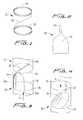
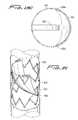
- FIG. 1a flow regulating device constructed in accordance with a preferred embodiment of the subject invention, and designated generally by reference numeral 10 .
- Regulating device 10includes an elongated frame 12 that consists of upper and lower crown-shaped or wave-like rings 14 and 16 . That is, each ring has connecting V-shapes as shown.
- These rings 14 , 16are preferably larger in diameter than the host vein in their expanded placement (deployed) configuration, to ensure that the device remains in a desired position and orientation after implantation.
- the diameter of the ringsmay be about 1.15% to about 1.30% larger than the diameter of the intended host vein, and more preferably about 1.20% to about 1.25% larger, although clearly other sizes are contemplated.
- Rings 14 and 16are connected to one another by at least one connective or linking member in the form of a bar or wire 18 .
- a bar or wire 18For ease of illustration, only one connective wire 18 is shown in FIG. 1 .
- Bar or wire 18is curved and adapted and configured to follow the circumference of the host vessel.
- the bar or wire 18is attached to the opposed rings 14 and 16 of frame 12 at locations that are about 180° apart from one another, as shown. This gives frame 12 an inherent flexibility and enables it to move with the natural movements (e.g., peristaltic) of the vein and to accommodate movement of the leg.
- the device 10can be reduced to approximately 1 ⁇ 5 of the final implanted diameter and could be introduced into a blood vessel through a relatively small delivery device.
- a device having a working diameter of 6 F to 8 Fcould be used.
- device 10includes a valve member 20 that is operatively associated with frame 12 for regulating the flow of blood through a vessel by moving between open and closed positions.
- Valve member 20(as well as the other members disclosed herein) is preferably formed from a sheet of ultra thin membrane material such as a non-expandable PTFE material or the like. It is envisioned that the membranes disclosed herein could be bonded or otherwise coated with an anti-clotting or anti-coagulant agent such as Heparin and/or an anti-proliferative coating to retard the body's desire to reject the implant.
- valve membrane 20has a narrow elongated neck portion 22 for attachment to the upper ring 14 of frame 12 and a wide body portion 24 for attachment to the lower ring 16 of frame 12 .
- the narrow neck portion 22 as shownextends across the diameter of the device, and preferably has a length greater than a radius of the device (ring) and slightly less than the diameter of the ring.
- the attachment locations ( 22 a of neck portion 22 and 24 a , 24 b of body portion 24 ) of the membrane 20 on each ringare preferably approximately 180° degrees from one another so that the body portion 24 of the membrane 20 will extend substantially if not entirely across the expanse of frame in the closed position shown in FIG. 4 .
- the membranecould be attached to ring 16 along its curved perimeter or attached at specific points, e.g. 24 a , 24 b , or at additional points.
- blood flowing through the blood vessel 30 in the downstream direction indicted by arrow “A”will act against the valve membrane 20 in such a manner so as to push the wide body portion 24 of the membrane 20 against the wall of the blood vessel 30 .
- bloodwill flow freely through the frame 12 , impeded only incidentally by the narrow neck portion 22 of membrane 20 extending across the device.
- blood flowing through the blood vessel 30 in the upstream direction indicated by arrow “B”will act against the valve membrane 20 in such a manner so as to push the wide body portion 24 in a direction as shown, substantially if not entirely closing off blood flow through the blood vessel 30 .
- the wide body portion 24Due to the length of the narrow part 22 of the valve membrane 20 , the wide body portion 24 will close at a relatively steep angle (e.g., 30°). This is important because the steeper the closure angle, the less force required to push the valve membrane back to an open position with the natural blood pressure.
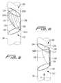
- an implantable device 100that includes a frame 112 having two axially spaced part substantially circular rings 114 , 116 and a connecting bar 118 , with an ultra thin, generally triangular shaped membrane 120 operatively associated therewith. As shown, each of the rings 114 , 116 is positioned at an angle, preferably obtuse as shown, to the connecting bar 118 .
- the lower apex of the triangular membrane 120is attached to the lower ring portion 116 of frame 112 (attachment region 121 a ), and the upper apices of the triangular membrane 120 are attached to the upper ring portion 114 of frame 112 at diametrically opposed positions (attachment regions 122 a , 122 b ).
- the upper portion of the membrane 120is loosely attached to the upper ring portion 114 , allowing it to slide down the ring during insertion.
- the lower portion of the membrane 120is attached to the lower ring portion 116 in the same general area as the connecting rod 118 .
- the membranehas a curved or convex outer surface 119 in the flow blocking position of FIG. 5 and a curved or convex outer surface 117 facing in the opposite direction (radially) in the blood flow position of FIG. 6 (see arrow D).
- the frame 112(and frame 12 ) is made from a shape-memory or super-elastic material such as Nitinol or a similar material, so as to enable the collapse and recovery of the rings during implantation in blood vessel 30 .
- the ultra thin membrane 120is preferably made from a material such as PTFE, and may be provided with an anti-clotting drug and/or an anti-proliferative agent.
- valve membrane 120can have a small slit or hole 126 adjacent the lower apex of the membrane near the connection with lower ring portion 116 to allow some of the blood trapped behind to flow back through the membrane. This will reduce the likelihood of clotting.
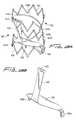
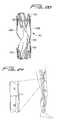
- FIGS. 11-13illustrate a variation of the flow regulating device of FIG. 5 .
- device 700has a support 712 having first and second substantially annular members forming ring-like members 714 , 716 which are substantially perpendicular to the direction of blood flow and substantially perpendicular to the linking member 718 which joins the two ring members 714 , 716 .
- the linking member 718as shown in this embodiment is substantially straight but could alternatively be curved.
- the support 712as best shown in FIG.
- 11Dis formed from a single wire which loops around in almost a complete 360 degree circle to form ring member 714 , extends perpendicular to a diameter of the ring 714 to form linking member 718 , and then loops around in almost a complete 360 degree circle to form ring 716 .
- a substantially triangular membrane 720is mounted to the support 712 .
- the lower region of the membrane 720has two adjacent flaps 722 a formed by a fold at the bottom edge 724 for attachment to the lower ring 716 as the wire extends through the flaps as shown in FIGS. 11A and 11B .
- the upper region of the membrane 720has two flaps 725 , 726 spaced about 180 degrees apart and formed by two folds in the edge 727 of the membrane 720 .
- the flaps 725 , 726receive a portion 717 , 719 , respectively, of the wire support 712 (see FIG. 11C ).
- Flaps 722 areceive portion 729 of wire support 712 therethrough. Gap 723 allows for the backflow of blood when the membrane is in the closed position.
- the W-shapecreates an outwardly curved surface 728 a facing in a first direction, and two curved surfaces 728 b , 728 c facing in a second opposite direction.
- Backflow of bloodreturns the membrane to the position of FIG. 11A .
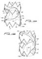
- FIG. 13The collapsed position of flow regulating device 700 is shown in FIG. 13 with the ring portions 714 , 716 collapsing to a more elongated (straighter configuration) to reduce the profile for insertion of the device 700 .
- top ring 714bends toward the linking member 718 while bottom ring 716 bends away and towards linear alignment with linking member 718 .
- the support 712 ′is similar to support 712 of FIG. 12 except first and second rings 714 ′, 716 ′ are joined by a linking member 718 ′ which has a sinuous shape intermediate portion 719 which increases flexibility.
- FIGS. 14-15illustrate an alternate embodiment of the flow regulating device, designated by generally by reference numeral 300 , wherein the support 312 has annular rings 314 and 316 of crown or wavy configuration and a suture 340 extending from the support 312 to the membrane 320 .
- support 312can be formed from a cut tube, preferably laser cut, into the configuration shown wherein the annular ring-like members 314 and 316 each have a crown shaped formed by connected V-shaped members.
- the alternating apices 315 a , 315 b and 317 a , 317 b of the V-shapesare rounded. (For clarity, not all the apices are labelled.)
- a curved linking member 318 joining the first and second rings 314 , 316preferably extends through a curve of about 90 degrees. That is, it extends from ring 314 at a region 314 a which is spaced about 90 degrees apart from the region 316 a where it extends from ring 316 .
- linking memberAlthough a single linking member is shown, as with the other embodiments disclosed herein, two or more linking members could be provided. Also, as with the other embodiments disclosed herein, the linking members could be spaced apart at regions different than 90 degrees apart, such as 180 degrees, 120 degrees, etc.
- Membrane 320includes flaps 325 , 326 in the upper region, spaced about 180 degrees apart and formed by folds in the edge 327 of the membrane 320 .
- the flaps 325 , 326extend through a slot 317 , 319 , respectively, formed in the ring portions 314 , 312 .
- the lower region of the substantially triangular membrane 320has a single flap 322 a (although alternatively multiple flaps could be formed). Flap 322 a is formed by a fold at the bottom edge 324 for attachment by extending through a slot formed in the lower ring 316 .
- a flexible material 340shown in the form of a suture, extends from a middle region of the membrane 320 to the upper ring 314 . Preferably it loops through a slot in the ring at one end and is stitched to the membrane at the other end.
- the flexible materialcould alternately be integral with the membrane 320 , i.e. formed of the same material.
- the flexible materialwould be in the form of a strap attached at its other end to the ring and would function in the same manner as suture 340 described herein.
- Suture 340is shown in the untensioned position of FIG. 14 a , corresponding the closed (blocking) position of the membrane 320 .
- the bloodacts on membrane 320 to move membrane 320 toward the opposing side of the support 312 .
- the suture 340is tensioned as shown in FIG. 15A to limit the movement of the membrane 320 . This keeps the membrane 320 away from the edge of the support 312 and away from the vessel wall. It also maintains the wavy configuration of the membrane. As shown in FIGS.
- the wavy shapeis formed by the inwardly curved surface 328 facing in a first direction, two curved surfaces 329 a , 329 b facing in a second opposite direction, and two curved surface 326 a , 326 b facing in the first direction, as the flaps are held in position through the slots of the support.
- the length of the suturecan be varied to adjust the extent of movement of the membrane.
- the collapsed configuration of the flow regulating device 300is shown in FIG. 16 positioned in a delivery catheter C.
- FIG. 17illustrates an alternate embodiment of the flow regulating device, shown for ease of illustration with the ring-like support of FIG. 11A but it is also contemplated that the crown-shaped support could be utilized.
- the support 350has an indent formed in the lower ring 362 a to create a gap 364 . That is, a dent is formed in the ring such that a portion of the circumference extends toward a center of the ring-like support to create the gap.
- This gapenables the back flow of a limited amount of blood in the direction of arrow J between the device 300 and the vessel wall when the membrane 370 is in the closed position to reduce the likelihood of clotting.
- the devicehas a suture 372 functioning in the same manner as suture 340 of FIG. 15 . As described with respect to FIG. 15 , other flexible material besides suture 372 could be utilized.
- lower ring 816 of frame 812has a dent or indentation so it is spaced from the vessel wall. That is, as can be seen in FIG. 21 , upper ring 814 fills the diameter of the vessel wall while the lower ring configuration forms a gap 817 with the vessel wall to allow back flow of blood.
- FIGS. 18-20illustrate an alternate embodiment of the flow regulating device, designated generally by reference numeral 400 .
- Support 412is similar to support 312 of FIG. 14A in that it has two annular ring portions 414 , 416 which are crown shaped. However, support 412 has two linking members 418 a , 418 b , each of which extends through an approximate 90 degree curve (twist). That is, region 415 a of ring 414 from which linking member 418 a extends, is about 90 degrees out of phase from region 417 a of ring 416 , from which the other end of linking ember 418 a extends. Region 415 b of ring 414 from which linking member 418 b extends, is about 90 degrees out of phase from region 417 b of ring 416 , from which the other end of linking ember 418 a extends.
- Membrane 420has a elongated narrow neck portion 422 and a wider body portion 424 .
- the narrow neck portion 422 as shownextends across the diameter of the device in the open position, and preferably has a length greater than a radius of the device (ring) and less than the diameter of the ring.
- Neck portion 422is attached to upper ring 414 by engagement of flap 425 with a portion of the ring extending therethrough as it extends through slot 413 .
- the body portion 424includes flaps 426 a , 426 b in the lower region, preferably spaced about 180 degrees apart, and formed by two folds in the edge 427 of the membrane 320 .
- the flaps 426 a , 426 bextend through slots 419 a , 419 b respectively, formed in the ring portion 416 .
- body portion 424extends at a slight angle to a diameter of the ring 416 and neck portion 422 extends substantially perpendicular to the ring 414 .
- the bloodacts on membrane 420 to move membrane 420 to the flow permitting position wherein the body portion 424 is moved toward an edge of the support 412 and the neck portion 42 flips so that it extends in an arc upwardly from the body portion and across a portion of the support 412 .
- convex surface 429is adjacent the edge of the support 412 , but preferably spaced from the edge and the vessel wall.
- the length of the neck portion 422limits the extent of travel of the membrane 420 and can be adjusted in manufacture accordingly to vary the extent of movement of the membrane 420 .
- the diameter of the rings 414 , 416is reduced to thereby reduce the profile.
- the supportis preferably composed of a laser cut tube.
- the supportcan be formed from wire(s).
- wire 512 of device 500is formed into two crown ring shapes 514 , 516 . Rings 514 and 516 are formed by a 180 degree linking member 518 .
- Membrane 520is similar to membrane 420 .
- FIG. 23is similar to FIG. 22 , however, the rings 614 and 616 are connected by two linking members 618 a and 618 b , each extending through a 90 degree curve.
- the first wire 613forms about half of ring 614 , linking member 618 b and about half of ring 616 .
- Wire 615forms the other section (other half) of ring 614 , linking member 618 a , and the other section of ring 616 .
- the membrane 620is substantially identical to membrane 420 of the embodiment of FIG. 19 .
- FIG. 24One example of the location of placement of the flow regulating device in a patient's leg is shown in FIG. 24 with areas A 1 and A 2 showing possible placement sites of the device, e.g. upstream or downstream of the native valve V.
- Device 200includes a frame 212 having opposed flexible straps 214 , 216 and a connecting structure 218 .
- Straps 214 and 216are preferably formed from a shape memory material that is normally biased into a coiled or closed configuration, shown for example in FIG. 7 .
- a generally triangular membrane 220is attached to frame 212 in a manner similar to the way in which membrane 120 is attached to frame 112 .
- the rings 214 , 216 of frame 212are adapted and configured for securement in an expanded or open position, shown in FIG. 8 , through the interaction of a locking tangs 217 and apertures 215 .
- device 200is implanted in a blood vessel using a balloon catheter 240 . More particularly, rings 214 and 216 are moved from a closed position to an expanded position by inflating balloon 242 . Upon expansion, to a desired position, tangs 217 engage apertures 215 to lock the rings 214 and 216 in a desired position. The balloon 242 is then deflated and the catheter 240 is removed from the blood vessel so the device 200 can regulate the flow of blood through the vessel, in the manner described previously with respect to device 100 .
- the ringscan be shaped to have a size larger than the diameter of the vessel and therefore, depending on the size of the vessel, may not assume a circular shape but have an oval shape pressing against the vessel wall toward a circular configuration.
Landscapes
- Health & Medical Sciences (AREA)
- Cardiology (AREA)
- Engineering & Computer Science (AREA)
- Biomedical Technology (AREA)
- Heart & Thoracic Surgery (AREA)
- Transplantation (AREA)
- Oral & Maxillofacial Surgery (AREA)
- Vascular Medicine (AREA)
- Life Sciences & Earth Sciences (AREA)
- Animal Behavior & Ethology (AREA)
- General Health & Medical Sciences (AREA)
- Public Health (AREA)
- Veterinary Medicine (AREA)
- Prostheses (AREA)
Abstract
Description
Claims (21)
Priority Applications (13)
| Application Number | Priority Date | Filing Date | Title |
|---|---|---|---|
| US11/801,691US7811316B2 (en) | 2006-05-25 | 2007-05-10 | Device for regulating blood flow |
| AU2007353471AAU2007353471A1 (en) | 2007-05-10 | 2007-09-21 | Device for regulating blood flow |
| EP07838616AEP2155116A1 (en) | 2007-05-10 | 2007-09-21 | Device for regulating blood flow |
| JP2010507372AJP2010526580A (en) | 2007-05-10 | 2007-09-21 | Blood flow control device |
| PCT/US2007/020449WO2008140466A1 (en) | 2007-05-10 | 2007-09-21 | Device for regulating blood flow |
| US12/319,176US8092517B2 (en) | 2006-05-25 | 2009-01-02 | Device for regulating blood flow |
| PCT/US2009/000001WO2009088957A1 (en) | 2006-05-25 | 2009-01-02 | Device for regulating blood flow |
| US12/713,476US8109993B2 (en) | 2006-05-25 | 2010-02-26 | Device for regulating blood flow |
| US13/344,928US9155618B2 (en) | 2006-05-25 | 2012-01-06 | Device for regulating blood |
| US13/367,013US8968388B2 (en) | 2006-05-25 | 2012-02-06 | Device for regulating blood flow |
| US14/880,546US9763786B2 (en) | 2006-05-25 | 2015-10-12 | Device for regulating blood flow |
| US15/707,728US10500050B2 (en) | 2006-05-25 | 2017-09-18 | Device for regulating blood flow |
| US16/707,795US20200179118A1 (en) | 2006-05-25 | 2019-12-09 | Device for regulating blood flow |
Applications Claiming Priority (3)
| Application Number | Priority Date | Filing Date | Title |
|---|---|---|---|
| US80840606P | 2006-05-25 | 2006-05-25 | |
| US80948306P | 2006-05-31 | 2006-05-31 | |
| US11/801,691US7811316B2 (en) | 2006-05-25 | 2007-05-10 | Device for regulating blood flow |
Related Parent Applications (1)
| Application Number | Title | Priority Date | Filing Date |
|---|---|---|---|
| US11/801,489Continuation-In-PartUS20070276467A1 (en) | 2006-05-25 | 2007-05-10 | Device for regulating blood flow |
Related Child Applications (2)
| Application Number | Title | Priority Date | Filing Date |
|---|---|---|---|
| US11/801,489Continuation-In-PartUS20070276467A1 (en) | 2006-05-25 | 2007-05-10 | Device for regulating blood flow |
| US12/319,176Continuation-In-PartUS8092517B2 (en) | 2006-05-25 | 2009-01-02 | Device for regulating blood flow |
Publications (2)
| Publication Number | Publication Date |
|---|---|
| US20070288086A1 US20070288086A1 (en) | 2007-12-13 |
| US7811316B2true US7811316B2 (en) | 2010-10-12 |
Family
ID=40002891
Family Applications (1)
| Application Number | Title | Priority Date | Filing Date |
|---|---|---|---|
| US11/801,691Expired - Fee RelatedUS7811316B2 (en) | 2006-05-25 | 2007-05-10 | Device for regulating blood flow |
Country Status (5)
| Country | Link |
|---|---|
| US (1) | US7811316B2 (en) |
| EP (1) | EP2155116A1 (en) |
| JP (1) | JP2010526580A (en) |
| AU (1) | AU2007353471A1 (en) |
| WO (1) | WO2008140466A1 (en) |
Cited By (45)
| Publication number | Priority date | Publication date | Assignee | Title |
|---|---|---|---|---|
| US20100256743A1 (en)* | 2006-05-25 | 2010-10-07 | Deep Vein Medical, Inc. | Device for regulating blood flow |
| US9763657B2 (en) | 2010-07-21 | 2017-09-19 | Mitraltech Ltd. | Techniques for percutaneous mitral valve replacement and sealing |
| USD800908S1 (en) | 2016-08-10 | 2017-10-24 | Mitraltech Ltd. | Prosthetic valve element |
| US9974651B2 (en) | 2015-02-05 | 2018-05-22 | Mitral Tech Ltd. | Prosthetic valve with axially-sliding frames |
| US10188397B2 (en) | 2006-03-13 | 2019-01-29 | Pneumrx, Inc. | Torque alleviating intra-airway lung volume reduction compressive implant structures |
| USD841813S1 (en) | 2017-08-03 | 2019-02-26 | Cardiovalve Ltd. | Prosthetic heart valve element |
| US20190069996A1 (en)* | 2017-09-07 | 2019-03-07 | Edwards Lifesciences Corporation | Integral flushing solution for blood stasis prevention in artificial heart valves |
| US10226341B2 (en) | 2011-08-05 | 2019-03-12 | Cardiovalve Ltd. | Implant for heart valve |
| US10245143B2 (en) | 2011-08-05 | 2019-04-02 | Cardiovalve Ltd. | Techniques for percutaneous mitral valve replacement and sealing |
| US10376361B2 (en) | 2011-08-05 | 2019-08-13 | Cardiovalve Ltd. | Techniques for percutaneous mitral valve replacement and sealing |
| US10390952B2 (en) | 2015-02-05 | 2019-08-27 | Cardiovalve Ltd. | Prosthetic valve with flexible tissue anchor portions |
| US10492908B2 (en) | 2014-07-30 | 2019-12-03 | Cardiovalve Ltd. | Anchoring of a prosthetic valve |
| US10575948B2 (en) | 2017-08-03 | 2020-03-03 | Cardiovalve Ltd. | Prosthetic heart valve |
| US10631982B2 (en) | 2013-01-24 | 2020-04-28 | Cardiovale Ltd. | Prosthetic valve and upstream support therefor |
| US10856975B2 (en) | 2016-08-10 | 2020-12-08 | Cardiovalve Ltd. | Prosthetic valve with concentric frames |
| US10888421B2 (en) | 2017-09-19 | 2021-01-12 | Cardiovalve Ltd. | Prosthetic heart valve with pouch |
| US10952842B2 (en) | 2017-06-07 | 2021-03-23 | W. L. Gore & Associates, Inc. | Prosthetic valve with improved washout |
| US10973640B2 (en)* | 2015-12-03 | 2021-04-13 | Medtronic Vascular, Inc. | Venous valve prostheses |
| US11109964B2 (en) | 2010-03-10 | 2021-09-07 | Cardiovalve Ltd. | Axially-shortening prosthetic valve |
| US11141268B2 (en) | 2009-12-08 | 2021-10-12 | Cardiovalve Ltd. | Prosthetic heart valve with upper and lower skirts |
| US11202706B2 (en) | 2019-05-04 | 2021-12-21 | Vdyne, Inc. | Cinch device and method for deployment of a side-delivered prosthetic heart valve in a native annulus |
| US11234813B2 (en) | 2020-01-17 | 2022-02-01 | Vdyne, Inc. | Ventricular stability elements for side-deliverable prosthetic heart valves and methods of delivery |
| US11246704B2 (en) | 2017-08-03 | 2022-02-15 | Cardiovalve Ltd. | Prosthetic heart valve |
| US11253359B2 (en) | 2018-12-20 | 2022-02-22 | Vdyne, Inc. | Proximal tab for side-delivered transcatheter heart valves and methods of delivery |
| US11273032B2 (en) | 2019-01-26 | 2022-03-15 | Vdyne, Inc. | Collapsible inner flow control component for side-deliverable transcatheter heart valve prosthesis |
| US11273033B2 (en) | 2018-09-20 | 2022-03-15 | Vdyne, Inc. | Side-delivered transcatheter heart valve replacement |
| US11278437B2 (en) | 2018-12-08 | 2022-03-22 | Vdyne, Inc. | Compression capable annular frames for side delivery of transcatheter heart valve replacement |
| US11291545B2 (en) | 2011-08-05 | 2022-04-05 | Cardiovalve Ltd. | Implant for heart valve |
| US11298227B2 (en)* | 2019-03-05 | 2022-04-12 | Vdyne, Inc. | Tricuspid regurgitation control devices for orthogonal transcatheter heart valve prosthesis |
| US11331186B2 (en) | 2019-08-26 | 2022-05-17 | Vdyne, Inc. | Side-deliverable transcatheter prosthetic valves and methods for delivering and anchoring the same |
| US11344413B2 (en) | 2018-09-20 | 2022-05-31 | Vdyne, Inc. | Transcatheter deliverable prosthetic heart valves and methods of delivery |
| US11344412B2 (en) | 2019-08-20 | 2022-05-31 | Vdyne, Inc. | Delivery and retrieval devices and methods for side-deliverable transcatheter prosthetic valves |
| US11382746B2 (en) | 2017-12-13 | 2022-07-12 | Cardiovalve Ltd. | Prosthetic valve and delivery tool therefor |
| US11633277B2 (en) | 2018-01-10 | 2023-04-25 | Cardiovalve Ltd. | Temperature-control during crimping of an implant |
| US11653910B2 (en) | 2010-07-21 | 2023-05-23 | Cardiovalve Ltd. | Helical anchor implantation |
| US11786366B2 (en) | 2018-04-04 | 2023-10-17 | Vdyne, Inc. | Devices and methods for anchoring transcatheter heart valve |
| US11793633B2 (en) | 2017-08-03 | 2023-10-24 | Cardiovalve Ltd. | Prosthetic heart valve |
| US11937795B2 (en) | 2016-02-16 | 2024-03-26 | Cardiovalve Ltd. | Techniques for providing a replacement valve and transseptal communication |
| US12029646B2 (en) | 2017-08-03 | 2024-07-09 | Cardiovalve Ltd. | Prosthetic heart valve |
| US12053379B2 (en) | 2016-08-01 | 2024-08-06 | Cardiovalve Ltd. | Minimally-invasive delivery systems |
| US12138158B2 (en) | 2019-03-14 | 2024-11-12 | Vdyne, Inc. | Side-deliverable transcatheter prosthetic valves and methods for delivering and anchoring the same |
| US12186187B2 (en) | 2018-09-20 | 2025-01-07 | Vdyne, Inc. | Transcatheter deliverable prosthetic heart valves and methods of delivery |
| US12310850B2 (en) | 2018-09-20 | 2025-05-27 | Vdyne, Inc. | Transcatheter deliverable prosthetic heart valves and methods of delivery |
| US12343256B2 (en) | 2019-01-10 | 2025-07-01 | Vdyne, Inc. | Anchor hook for side-delivery transcatheter heart valve prosthesis |
| US12357459B2 (en) | 2020-12-03 | 2025-07-15 | Cardiovalve Ltd. | Transluminal delivery system |
Families Citing this family (40)
| Publication number | Priority date | Publication date | Assignee | Title |
|---|---|---|---|---|
| US8092517B2 (en)* | 2006-05-25 | 2012-01-10 | Deep Vein Medical, Inc. | Device for regulating blood flow |
| US7811316B2 (en) | 2006-05-25 | 2010-10-12 | Deep Vein Medical, Inc. | Device for regulating blood flow |
| JP2009538184A (en)* | 2006-05-25 | 2009-11-05 | インターナショナル アンド サージカル イノヴェイションズ リミテッド ライアビリティ カンパニー | Blood flow adjustment device |
| WO2009088957A1 (en)* | 2006-05-25 | 2009-07-16 | Interventional & Surgical Innovations, Llc | Device for regulating blood flow |
| US20090105813A1 (en) | 2007-10-17 | 2009-04-23 | Sean Chambers | Implantable valve device |
| US20090105810A1 (en)* | 2007-10-17 | 2009-04-23 | Hancock Jaffe Laboratories | Biological valve for venous valve insufficiency |
| US8100962B2 (en) | 2008-01-08 | 2012-01-24 | Cook Medical Technologies Llc | Flow-deflecting prosthesis for treating venous disease |
| ATE507801T1 (en)* | 2008-03-27 | 2011-05-15 | Ab Medica Spa | VALVE PROSTHESIS FOR IMPLANTATION IN BODY VESSELS |
| DE102008002397A1 (en)* | 2008-06-12 | 2009-12-17 | Biotronik Vi Patent Ag | Implantable device |
| WO2010078603A2 (en)* | 2009-01-02 | 2010-07-08 | Deep Vein Medical, Inc. | Device for regulating blood flow |
| US8372140B2 (en)* | 2009-01-07 | 2013-02-12 | Cook Medical Technologies Llc | Implantable valve prosthesis with independent frame elements |
| US8348997B2 (en)* | 2009-02-24 | 2013-01-08 | Medtronic Vascular, Inc. | One-way replacement valve |
| US8075611B2 (en)* | 2009-06-02 | 2011-12-13 | Medtronic, Inc. | Stented prosthetic heart valves |
| US8475525B2 (en)* | 2010-01-22 | 2013-07-02 | 4Tech Inc. | Tricuspid valve repair using tension |
| US9307980B2 (en) | 2010-01-22 | 2016-04-12 | 4Tech Inc. | Tricuspid valve repair using tension |
| US10058323B2 (en) | 2010-01-22 | 2018-08-28 | 4 Tech Inc. | Tricuspid valve repair using tension |
| WO2011115799A2 (en) | 2010-03-17 | 2011-09-22 | Deep Vein Medical, Inc. | Fatigue-resistant flow regulating device and manufacturing methods |
| EP2598044B1 (en)* | 2010-07-27 | 2019-03-13 | Incept, LLC | Apparatus for treating neurovascular venous outflow obstruction |
| AU2011202120B1 (en)* | 2011-05-09 | 2012-09-13 | Cook Medical Technologies Llc | Paraplegia prevention valve for stent grafts |
| SE536244C2 (en)* | 2011-05-20 | 2013-07-16 | Bertil Ingvar Burstroem | Device for single-directional wiring |
| EP3281608B1 (en) | 2012-02-10 | 2020-09-16 | CVDevices, LLC | Medical product comprising a frame and visceral pleura |
| ITTO20120372A1 (en)* | 2012-04-27 | 2013-10-28 | Marcio Scorsin | MONOCUSPIDE CARDIAC VALVE PROSTHESIS |
| JP2015536744A (en)* | 2012-12-06 | 2015-12-24 | マイトラリクス リミテッドMitralix Ltd. | Device and method for replacement of heart valve function |
| CN105007832B (en) | 2013-01-09 | 2018-01-23 | 4科技有限公司 | Organize ancora equipment |
| CA2900862C (en) | 2013-02-11 | 2017-10-03 | Cook Medical Technologies Llc | Expandable support frame and medical device |
| US9907681B2 (en) | 2013-03-14 | 2018-03-06 | 4Tech Inc. | Stent with tether interface |
| CN105101909B (en)* | 2013-03-15 | 2018-03-27 | 纽姆克斯股份有限公司 | Intra-airway lung volume reduction compression implant structure with reduced torque |
| GB2514135B (en)* | 2013-05-14 | 2015-04-15 | Cook Medical Technologies Llc | Implantable flow diverter |
| GB2519932B (en)* | 2013-08-13 | 2015-10-21 | Cook Medical Technologies Llc | Implantable flow adjuster |
| US10022114B2 (en) | 2013-10-30 | 2018-07-17 | 4Tech Inc. | Percutaneous tether locking |
| US10052095B2 (en) | 2013-10-30 | 2018-08-21 | 4Tech Inc. | Multiple anchoring-point tension system |
| EP2918248A1 (en) | 2014-03-11 | 2015-09-16 | Epygon Sasu | An expandable stent-valve and a delivery device |
| EP2918247A1 (en) | 2014-03-11 | 2015-09-16 | Epygon Sasu | A prosthetic valve and a delivery device |
| WO2015193728A2 (en) | 2014-06-19 | 2015-12-23 | 4Tech Inc. | Cardiac tissue cinching |
| US9907547B2 (en) | 2014-12-02 | 2018-03-06 | 4Tech Inc. | Off-center tissue anchors |
| CN109310497B (en)* | 2017-02-07 | 2022-02-01 | 上海甲悦医疗器械有限公司 | Device for treating tricuspid regurgitation |
| RU2722797C1 (en)* | 2019-03-19 | 2020-06-03 | Александр Васильевич Самков | Artificial heart valve |
| WO2021209334A1 (en)* | 2020-04-17 | 2021-10-21 | Cortronik GmbH | Venous valve prosthesis |
| CN115462934B (en)* | 2022-10-08 | 2023-07-14 | 浙江归创医疗科技有限公司 | Detachable venous valve |
| WO2024163407A1 (en)* | 2023-01-30 | 2024-08-08 | Edwards Lifesciences Corp | Prosthetic valves and oval stents for flow balancing |
Citations (73)
| Publication number | Priority date | Publication date | Assignee | Title |
|---|---|---|---|---|
| US3589392A (en) | 1969-05-05 | 1971-06-29 | Louis C Meyer | Split leaflet check valve for cardiac surgery and the like |
| US3671979A (en) | 1969-09-23 | 1972-06-27 | Univ Utah | Catheter mounted artificial heart valve for implanting in close proximity to a defective natural heart valve |
| US4218782A (en) | 1977-05-25 | 1980-08-26 | Biocoating Anpartsselskab | Heart valve prosthesis and method for the production thereof |
| US4759758A (en) | 1984-12-07 | 1988-07-26 | Shlomo Gabbay | Prosthetic heart valve |
| US4787901A (en) | 1984-07-17 | 1988-11-29 | Doguhan Baykut | Two-way acting valve and cardiac valve prosthesis |
| US4994077A (en) | 1989-04-21 | 1991-02-19 | Dobben Richard L | Artificial heart valve for implantation in a blood vessel |
| US5104404A (en)* | 1989-10-02 | 1992-04-14 | Medtronic, Inc. | Articulated stent |
| EP0520126A1 (en) | 1991-06-25 | 1992-12-30 | Sante Camilli | Artificial venous value |
| US5500014A (en) | 1989-05-31 | 1996-03-19 | Baxter International Inc. | Biological valvular prothesis |
| US5607465A (en) | 1993-12-14 | 1997-03-04 | Camilli; Sante | Percutaneous implantable valve for the use in blood vessels |
| US5855601A (en) | 1996-06-21 | 1999-01-05 | The Trustees Of Columbia University In The City Of New York | Artificial heart valve and method and device for implanting the same |
| US5957949A (en) | 1997-05-01 | 1999-09-28 | World Medical Manufacturing Corp. | Percutaneous placement valve stent |
| US6027525A (en) | 1996-05-23 | 2000-02-22 | Samsung Electronics., Ltd. | Flexible self-expandable stent and method for making the same |
| US6110201A (en) | 1999-02-18 | 2000-08-29 | Venpro | Bifurcated biological pulmonary valved conduit |
| US6132457A (en) | 1997-10-22 | 2000-10-17 | Triad Vascular Systems, Inc. | Endovascular graft having longitudinally displaceable sections |
| US6200336B1 (en) | 1998-06-02 | 2001-03-13 | Cook Incorporated | Multiple-sided intraluminal medical device |
| US20010010017A1 (en) | 1996-12-31 | 2001-07-26 | Brice Letac | Alve prosthesis for implantation in body channels |
| WO2001054625A1 (en) | 2000-01-31 | 2001-08-02 | Cook Biotech Incorporated | Stent valves and uses of same |
| US6270526B1 (en) | 1993-11-01 | 2001-08-07 | 3F Therapeutics, Inc. | Replacement semilunar heart valves using flexible tubes |
| US6287334B1 (en)* | 1996-12-18 | 2001-09-11 | Venpro Corporation | Device for regulating the flow of blood through the blood system |
| US6299637B1 (en) | 1999-08-20 | 2001-10-09 | Samuel M. Shaolian | Transluminally implantable venous valve |
| US20010039450A1 (en) | 1999-06-02 | 2001-11-08 | Dusan Pavcnik | Implantable vascular device |
| US6315793B1 (en) | 1999-09-08 | 2001-11-13 | Medical Carbon Research Institute, Llc | Prosthetic venous valves |
| US20020099439A1 (en) | 2000-09-29 | 2002-07-25 | Schwartz Robert S. | Venous valvuloplasty device and method |
| US6425855B2 (en) | 1999-04-06 | 2002-07-30 | Cordis Corporation | Method for making a multi-laminate stent having superelastic articulated sections |
| US6440164B1 (en)* | 1999-10-21 | 2002-08-27 | Scimed Life Systems, Inc. | Implantable prosthetic valve |
| US6458153B1 (en) | 1999-12-31 | 2002-10-01 | Abps Venture One, Ltd. | Endoluminal cardiac and venous valve prostheses and methods of manufacture and delivery thereof |
| WO2002089869A2 (en)* | 2001-05-07 | 2002-11-14 | Rafael Medical Technologies Inc. | Intravascular platforms and associated devices |
| US6482228B1 (en) | 2000-11-14 | 2002-11-19 | Troy R. Norred | Percutaneous aortic valve replacement |
| US6503272B2 (en) | 2001-03-21 | 2003-01-07 | Cordis Corporation | Stent-based venous valves |
| US6517576B2 (en) | 2000-12-11 | 2003-02-11 | Shlomo Gabbay | Implantable patch prosthesis having one or more cusps for improved competency |
| US20030055492A1 (en) | 1999-08-20 | 2003-03-20 | Shaolian Samuel M. | Transluminally implantable venous valve |
| US6562068B2 (en) | 1999-06-08 | 2003-05-13 | William J. Drasler | In situ venous valve device and method of formation |
| US6569198B1 (en) | 2000-03-31 | 2003-05-27 | Richard A. Wilson | Mitral or tricuspid valve annuloplasty prosthetic device |
| US6572652B2 (en) | 2000-08-29 | 2003-06-03 | Venpro Corporation | Method and devices for decreasing elevated pulmonary venous pressure |
| US6585761B2 (en) | 2001-03-01 | 2003-07-01 | Syde A. Taheri | Prosthetic vein valve and method |
| US20030130726A1 (en) | 1999-09-10 | 2003-07-10 | Thorpe Patricia E. | Combination valve and stent for treating vascular reflux |
| US6602286B1 (en)* | 2000-10-26 | 2003-08-05 | Ernst Peter Strecker | Implantable valve system |
| US20030208261A1 (en) | 2000-03-03 | 2003-11-06 | Thorpe Patricia E. | Bulbous valve and stent for treating vascular reflux |
| US20030209835A1 (en) | 2002-05-10 | 2003-11-13 | Iksoo Chun | Method of forming a tubular membrane on a structural frame |
| US6676699B2 (en) | 2002-04-26 | 2004-01-13 | Medtronic Ave, Inc | Stent graft with integrated valve device and method |
| US20040019374A1 (en) | 2002-05-10 | 2004-01-29 | Hikmat Hojeibane | Frame based unidirectional flow prosthetic implant |
| US20040093070A1 (en)* | 2002-05-10 | 2004-05-13 | Hikmat Hojeibane | Frame based unidirectional flow prosthetic implant |
| US20040117004A1 (en) | 2002-05-16 | 2004-06-17 | Osborne Thomas A. | Stent and method of forming a stent with integral barbs |
| US6752828B2 (en) | 2002-04-03 | 2004-06-22 | Scimed Life Systems, Inc. | Artificial valve |
| US6767362B2 (en) | 2000-04-06 | 2004-07-27 | Edwards Lifesciences Corporation | Minimally-invasive heart valves and methods of use |
| US20040186558A1 (en) | 2001-02-05 | 2004-09-23 | Cook Incorporated | Implantable vascular device |
| US20040193253A1 (en) | 2001-04-30 | 2004-09-30 | Thorpe Patricia E | Replacement venous valve |
| US20040215339A1 (en) | 2002-10-24 | 2004-10-28 | Drasler William J. | Venous valve apparatus and method |
| US20040225352A1 (en) | 2003-03-12 | 2004-11-11 | Osborne Thomas A. | Prosthetic valve that permits retrograde flow |
| US20040260389A1 (en) | 2003-04-24 | 2004-12-23 | Cook Incorporated | Artificial valve prosthesis with improved flow dynamics |
| US20050059923A1 (en) | 2003-09-17 | 2005-03-17 | Ricardo Gamboa | Fenestration with intrinsic means of selective closure incorporated to a tubular body and used in interventional cardiovascular procedures |
| US6869444B2 (en) | 2000-05-22 | 2005-03-22 | Shlomo Gabbay | Low invasive implantable cardiac prosthesis and method for helping improve operation of a heart valve |
| US20050096735A1 (en) | 2003-10-31 | 2005-05-05 | Hikmat Hojeibane | Implantable valvular prosthesis |
| US20050137701A1 (en) | 2003-12-23 | 2005-06-23 | Sadra Medical | Locking heart valve anchor |
| US20050187614A1 (en) | 2004-02-20 | 2005-08-25 | Agnew Charles W. | Prosthetic valve with spacing member |
| US20050203617A1 (en) | 2004-02-27 | 2005-09-15 | Cardiacmd, Inc. | Prosthetic heart valves, scaffolding structures, and systems and methods for implantation of same |
| US6951571B1 (en) | 2004-09-30 | 2005-10-04 | Rohit Srivastava | Valve implanting device |
| US20050273159A1 (en) | 2004-01-22 | 2005-12-08 | Opie John C | Monocusp valve construction and defect closure device for deep vein regurgitation |
| US20060058889A1 (en) | 2004-09-10 | 2006-03-16 | Case Brian C | Prosthetic valve with pores |
| US20060089708A1 (en)* | 2002-02-20 | 2006-04-27 | Osse Francisco J | Venous bi-valve |
| US20060106454A1 (en) | 2004-10-29 | 2006-05-18 | Osborne Thomas A | Intraluminal medical device with cannula for controlled retrograde flow |
| US20060136044A1 (en) | 2004-10-06 | 2006-06-22 | Osborne Thomas A | Medical device with bioactive agent |
| US7087089B2 (en) | 2001-06-28 | 2006-08-08 | Cook Biotech Incorporated | Graft prosthesis devices containing renal capsule collagen |
| US20060190074A1 (en) | 2005-02-23 | 2006-08-24 | Boston Scientific Scimed, Inc. | Valve apparatus, system and method |
| US20060210597A1 (en) | 2005-03-19 | 2006-09-21 | Cook Biotech Incorporated | Prosthetic implants including ECM composite material |
| US20060259136A1 (en)* | 2005-05-13 | 2006-11-16 | Corevalve Sa | Heart valve prosthesis and methods of manufacture and use |
| US20060265053A1 (en) | 2005-05-17 | 2006-11-23 | Cook Incorporated | Prosthetic valve devices and methods of making and using such devices |
| US20060282157A1 (en) | 2005-06-10 | 2006-12-14 | Hill Jason P | Venous valve, system, and method |
| US7153324B2 (en) | 2003-07-31 | 2006-12-26 | Cook Incorporated | Prosthetic valve devices and methods of making such devices |
| US7201772B2 (en)* | 2003-07-08 | 2007-04-10 | Ventor Technologies, Ltd. | Fluid flow prosthetic device |
| US20070288086A1 (en) | 2006-05-25 | 2007-12-13 | Menno Kalmann | Device for regulating blood flow |
| US20090018636A1 (en) | 2007-07-09 | 2009-01-15 | Artventive, Inc. | Methods and apparatus for rapid endovascular vessel occlusion and blood flow interruption |
- 2007
- 2007-05-10USUS11/801,691patent/US7811316B2/ennot_activeExpired - Fee Related
- 2007-09-21AUAU2007353471Apatent/AU2007353471A1/ennot_activeAbandoned
- 2007-09-21WOPCT/US2007/020449patent/WO2008140466A1/enactiveApplication Filing
- 2007-09-21EPEP07838616Apatent/EP2155116A1/ennot_activeWithdrawn
- 2007-09-21JPJP2010507372Apatent/JP2010526580A/enactivePending
Patent Citations (83)
| Publication number | Priority date | Publication date | Assignee | Title |
|---|---|---|---|---|
| US3589392A (en) | 1969-05-05 | 1971-06-29 | Louis C Meyer | Split leaflet check valve for cardiac surgery and the like |
| US3671979A (en) | 1969-09-23 | 1972-06-27 | Univ Utah | Catheter mounted artificial heart valve for implanting in close proximity to a defective natural heart valve |
| US4218782A (en) | 1977-05-25 | 1980-08-26 | Biocoating Anpartsselskab | Heart valve prosthesis and method for the production thereof |
| US4787901A (en) | 1984-07-17 | 1988-11-29 | Doguhan Baykut | Two-way acting valve and cardiac valve prosthesis |
| US4759758A (en) | 1984-12-07 | 1988-07-26 | Shlomo Gabbay | Prosthetic heart valve |
| US4994077A (en) | 1989-04-21 | 1991-02-19 | Dobben Richard L | Artificial heart valve for implantation in a blood vessel |
| US5500014A (en) | 1989-05-31 | 1996-03-19 | Baxter International Inc. | Biological valvular prothesis |
| US5104404A (en)* | 1989-10-02 | 1992-04-14 | Medtronic, Inc. | Articulated stent |
| EP0520126A1 (en) | 1991-06-25 | 1992-12-30 | Sante Camilli | Artificial venous value |
| US5358518A (en) | 1991-06-25 | 1994-10-25 | Sante Camilli | Artificial venous valve |
| US6270526B1 (en) | 1993-11-01 | 2001-08-07 | 3F Therapeutics, Inc. | Replacement semilunar heart valves using flexible tubes |
| US5607465A (en) | 1993-12-14 | 1997-03-04 | Camilli; Sante | Percutaneous implantable valve for the use in blood vessels |
| US6027525A (en) | 1996-05-23 | 2000-02-22 | Samsung Electronics., Ltd. | Flexible self-expandable stent and method for making the same |
| US5855601A (en) | 1996-06-21 | 1999-01-05 | The Trustees Of Columbia University In The City Of New York | Artificial heart valve and method and device for implanting the same |
| US6979350B2 (en) | 1996-12-18 | 2005-12-27 | 3F Therapeutics, Inc. | Methods for regulating the flow of blood through the blood system |
| US6605112B1 (en) | 1996-12-18 | 2003-08-12 | Venpro Corporation | Device for regulating the flow of blood through the blood system |
| US6287334B1 (en)* | 1996-12-18 | 2001-09-11 | Venpro Corporation | Device for regulating the flow of blood through the blood system |
| US20010010017A1 (en) | 1996-12-31 | 2001-07-26 | Brice Letac | Alve prosthesis for implantation in body channels |
| US5957949A (en) | 1997-05-01 | 1999-09-28 | World Medical Manufacturing Corp. | Percutaneous placement valve stent |
| US6132457A (en) | 1997-10-22 | 2000-10-17 | Triad Vascular Systems, Inc. | Endovascular graft having longitudinally displaceable sections |
| US6200336B1 (en) | 1998-06-02 | 2001-03-13 | Cook Incorporated | Multiple-sided intraluminal medical device |
| US6974474B2 (en)* | 1998-06-02 | 2005-12-13 | Cook Incorporated | Multiple-sided intraluminal medical device |
| US6110201A (en) | 1999-02-18 | 2000-08-29 | Venpro | Bifurcated biological pulmonary valved conduit |
| US6425855B2 (en) | 1999-04-06 | 2002-07-30 | Cordis Corporation | Method for making a multi-laminate stent having superelastic articulated sections |
| US20010039450A1 (en) | 1999-06-02 | 2001-11-08 | Dusan Pavcnik | Implantable vascular device |
| US6562068B2 (en) | 1999-06-08 | 2003-05-13 | William J. Drasler | In situ venous valve device and method of formation |
| US6299637B1 (en) | 1999-08-20 | 2001-10-09 | Samuel M. Shaolian | Transluminally implantable venous valve |
| US20030055492A1 (en) | 1999-08-20 | 2003-03-20 | Shaolian Samuel M. | Transluminally implantable venous valve |
| US6315793B1 (en) | 1999-09-08 | 2001-11-13 | Medical Carbon Research Institute, Llc | Prosthetic venous valves |
| US20030130726A1 (en) | 1999-09-10 | 2003-07-10 | Thorpe Patricia E. | Combination valve and stent for treating vascular reflux |
| US6440164B1 (en)* | 1999-10-21 | 2002-08-27 | Scimed Life Systems, Inc. | Implantable prosthetic valve |
| US6458153B1 (en) | 1999-12-31 | 2002-10-01 | Abps Venture One, Ltd. | Endoluminal cardiac and venous valve prostheses and methods of manufacture and delivery thereof |
| US6652578B2 (en) | 1999-12-31 | 2003-11-25 | Abps Venture One, Ltd. | Endoluminal cardiac and venous valve prostheses and methods of manufacture and delivery thereof |
| WO2001054625A1 (en) | 2000-01-31 | 2001-08-02 | Cook Biotech Incorporated | Stent valves and uses of same |
| US20040210301A1 (en) | 2000-02-03 | 2004-10-21 | Obermiller Joseph F. | Implantable vascular device |
| US20030208261A1 (en) | 2000-03-03 | 2003-11-06 | Thorpe Patricia E. | Bulbous valve and stent for treating vascular reflux |
| US6569198B1 (en) | 2000-03-31 | 2003-05-27 | Richard A. Wilson | Mitral or tricuspid valve annuloplasty prosthetic device |
| US6767362B2 (en) | 2000-04-06 | 2004-07-27 | Edwards Lifesciences Corporation | Minimally-invasive heart valves and methods of use |
| US6869444B2 (en) | 2000-05-22 | 2005-03-22 | Shlomo Gabbay | Low invasive implantable cardiac prosthesis and method for helping improve operation of a heart valve |
| US6572652B2 (en) | 2000-08-29 | 2003-06-03 | Venpro Corporation | Method and devices for decreasing elevated pulmonary venous pressure |
| US20020099439A1 (en) | 2000-09-29 | 2002-07-25 | Schwartz Robert S. | Venous valvuloplasty device and method |
| US6602286B1 (en)* | 2000-10-26 | 2003-08-05 | Ernst Peter Strecker | Implantable valve system |
| US6482228B1 (en) | 2000-11-14 | 2002-11-19 | Troy R. Norred | Percutaneous aortic valve replacement |
| US6517576B2 (en) | 2000-12-11 | 2003-02-11 | Shlomo Gabbay | Implantable patch prosthesis having one or more cusps for improved competency |
| US20040186558A1 (en) | 2001-02-05 | 2004-09-23 | Cook Incorporated | Implantable vascular device |
| US6585761B2 (en) | 2001-03-01 | 2003-07-01 | Syde A. Taheri | Prosthetic vein valve and method |
| US6503272B2 (en) | 2001-03-21 | 2003-01-07 | Cordis Corporation | Stent-based venous valves |
| US20040193253A1 (en) | 2001-04-30 | 2004-09-30 | Thorpe Patricia E | Replacement venous valve |
| WO2002089869A2 (en)* | 2001-05-07 | 2002-11-14 | Rafael Medical Technologies Inc. | Intravascular platforms and associated devices |
| US7087089B2 (en) | 2001-06-28 | 2006-08-08 | Cook Biotech Incorporated | Graft prosthesis devices containing renal capsule collagen |
| US20060089708A1 (en)* | 2002-02-20 | 2006-04-27 | Osse Francisco J | Venous bi-valve |
| US7081131B2 (en)* | 2002-04-03 | 2006-07-25 | Boston Scientific Corporation | Artificial valve |
| US6752828B2 (en) | 2002-04-03 | 2004-06-22 | Scimed Life Systems, Inc. | Artificial valve |
| US6676699B2 (en) | 2002-04-26 | 2004-01-13 | Medtronic Ave, Inc | Stent graft with integrated valve device and method |
| US20040093070A1 (en)* | 2002-05-10 | 2004-05-13 | Hikmat Hojeibane | Frame based unidirectional flow prosthetic implant |
| US7270675B2 (en) | 2002-05-10 | 2007-09-18 | Cordis Corporation | Method of forming a tubular membrane on a structural frame |
| US20030209835A1 (en) | 2002-05-10 | 2003-11-13 | Iksoo Chun | Method of forming a tubular membrane on a structural frame |
| US20040019374A1 (en) | 2002-05-10 | 2004-01-29 | Hikmat Hojeibane | Frame based unidirectional flow prosthetic implant |
| US20040117004A1 (en) | 2002-05-16 | 2004-06-17 | Osborne Thomas A. | Stent and method of forming a stent with integral barbs |
| US20040215339A1 (en) | 2002-10-24 | 2004-10-28 | Drasler William J. | Venous valve apparatus and method |
| US20040225352A1 (en) | 2003-03-12 | 2004-11-11 | Osborne Thomas A. | Prosthetic valve that permits retrograde flow |
| US20070260327A1 (en) | 2003-04-24 | 2007-11-08 | Case Brian C | Artificial Valve Prosthesis with Improved Flow Dynamics |
| US20040260389A1 (en) | 2003-04-24 | 2004-12-23 | Cook Incorporated | Artificial valve prosthesis with improved flow dynamics |
| US7201772B2 (en)* | 2003-07-08 | 2007-04-10 | Ventor Technologies, Ltd. | Fluid flow prosthetic device |
| US7153324B2 (en) | 2003-07-31 | 2006-12-26 | Cook Incorporated | Prosthetic valve devices and methods of making such devices |
| US20050059923A1 (en) | 2003-09-17 | 2005-03-17 | Ricardo Gamboa | Fenestration with intrinsic means of selective closure incorporated to a tubular body and used in interventional cardiovascular procedures |
| US20050096735A1 (en) | 2003-10-31 | 2005-05-05 | Hikmat Hojeibane | Implantable valvular prosthesis |
| US20050137701A1 (en) | 2003-12-23 | 2005-06-23 | Sadra Medical | Locking heart valve anchor |
| US20050273159A1 (en) | 2004-01-22 | 2005-12-08 | Opie John C | Monocusp valve construction and defect closure device for deep vein regurgitation |
| US20050187614A1 (en) | 2004-02-20 | 2005-08-25 | Agnew Charles W. | Prosthetic valve with spacing member |
| US20050203617A1 (en) | 2004-02-27 | 2005-09-15 | Cardiacmd, Inc. | Prosthetic heart valves, scaffolding structures, and systems and methods for implantation of same |
| US7361189B2 (en)* | 2004-09-10 | 2008-04-22 | Cook Incorporated | Prosthetic valve with pores |
| US20060058889A1 (en) | 2004-09-10 | 2006-03-16 | Case Brian C | Prosthetic valve with pores |
| US6951571B1 (en) | 2004-09-30 | 2005-10-04 | Rohit Srivastava | Valve implanting device |
| US20060136044A1 (en) | 2004-10-06 | 2006-06-22 | Osborne Thomas A | Medical device with bioactive agent |
| US20060106454A1 (en) | 2004-10-29 | 2006-05-18 | Osborne Thomas A | Intraluminal medical device with cannula for controlled retrograde flow |
| US20060190074A1 (en) | 2005-02-23 | 2006-08-24 | Boston Scientific Scimed, Inc. | Valve apparatus, system and method |
| US20060210597A1 (en) | 2005-03-19 | 2006-09-21 | Cook Biotech Incorporated | Prosthetic implants including ECM composite material |
| US20060259136A1 (en)* | 2005-05-13 | 2006-11-16 | Corevalve Sa | Heart valve prosthesis and methods of manufacture and use |
| US20060265053A1 (en) | 2005-05-17 | 2006-11-23 | Cook Incorporated | Prosthetic valve devices and methods of making and using such devices |
| US20060282157A1 (en) | 2005-06-10 | 2006-12-14 | Hill Jason P | Venous valve, system, and method |
| US20070288086A1 (en) | 2006-05-25 | 2007-12-13 | Menno Kalmann | Device for regulating blood flow |
| US20090018636A1 (en) | 2007-07-09 | 2009-01-15 | Artventive, Inc. | Methods and apparatus for rapid endovascular vessel occlusion and blood flow interruption |
Non-Patent Citations (3)
| Title |
|---|
| International Preliminary Report on Patentability for PCT/US2007/020449 dated Nov. 10, 2009. |
| International Search Report for PCT/US2009/000001, dated Apr. 8, 2009. |
| Written Opinion of the International Searching Authority for PCT/US2009/000001, dated Apr. 8, 2009. |
Cited By (117)
| Publication number | Priority date | Publication date | Assignee | Title |
|---|---|---|---|---|
| US10188397B2 (en) | 2006-03-13 | 2019-01-29 | Pneumrx, Inc. | Torque alleviating intra-airway lung volume reduction compressive implant structures |
| US8109993B2 (en)* | 2006-05-25 | 2012-02-07 | Deep Vein Medical, Inc. | Device for regulating blood flow |
| US20120136429A1 (en)* | 2006-05-25 | 2012-05-31 | Deep Vein Medical, Inc. | Device for regulating blood flow |
| US8968388B2 (en)* | 2006-05-25 | 2015-03-03 | Deep Vein Medical, Inc. | Device for regulating blood flow |
| US20100256743A1 (en)* | 2006-05-25 | 2010-10-07 | Deep Vein Medical, Inc. | Device for regulating blood flow |
| US11839541B2 (en) | 2009-12-08 | 2023-12-12 | Cardiovalve Ltd. | Prosthetic heart valve with upper skirt |
| US11141268B2 (en) | 2009-12-08 | 2021-10-12 | Cardiovalve Ltd. | Prosthetic heart valve with upper and lower skirts |
| US11351026B2 (en) | 2009-12-08 | 2022-06-07 | Cardiovalve Ltd. | Rotation-based anchoring of an implant |
| US11109964B2 (en) | 2010-03-10 | 2021-09-07 | Cardiovalve Ltd. | Axially-shortening prosthetic valve |
| US12167963B2 (en) | 2010-03-10 | 2024-12-17 | Cardiovalve Ltd. | Method for use at a heart valve |
| US11426155B2 (en) | 2010-07-21 | 2022-08-30 | Cardiovalve Ltd. | Helical anchor implantation |
| US10531872B2 (en) | 2010-07-21 | 2020-01-14 | Cardiovalve Ltd. | Valve prosthesis configured for deployment in annular spacer |
| US9763657B2 (en) | 2010-07-21 | 2017-09-19 | Mitraltech Ltd. | Techniques for percutaneous mitral valve replacement and sealing |
| US12310575B2 (en) | 2010-07-21 | 2025-05-27 | Cardiovalve Ltd. | Helical anchor implantation |
| US10925595B2 (en) | 2010-07-21 | 2021-02-23 | Cardiovalve Ltd. | Valve prosthesis configured for deployment in annular spacer |
| US11653910B2 (en) | 2010-07-21 | 2023-05-23 | Cardiovalve Ltd. | Helical anchor implantation |
| US10512456B2 (en) | 2010-07-21 | 2019-12-24 | Cardiovalve Ltd. | Techniques for percutaneous mitral valve replacement and sealing |
| US11969163B2 (en) | 2010-07-21 | 2024-04-30 | Cardiovalve Ltd. | Valve prosthesis configured for deployment in annular spacer |
| US11291546B2 (en) | 2011-08-05 | 2022-04-05 | Cardiovalve Ltd. | Leaflet clip with collars |
| US10695173B2 (en) | 2011-08-05 | 2020-06-30 | Cardiovalve Ltd. | Techniques for percutaneous mitral valve replacement and sealing |
| US10245143B2 (en) | 2011-08-05 | 2019-04-02 | Cardiovalve Ltd. | Techniques for percutaneous mitral valve replacement and sealing |
| US11690712B2 (en) | 2011-08-05 | 2023-07-04 | Cardiovalve Ltd. | Clip-secured implant for heart valve |
| US11864995B2 (en) | 2011-08-05 | 2024-01-09 | Cardiovalve Ltd. | Implant for heart valve |
| US11344410B2 (en) | 2011-08-05 | 2022-05-31 | Cardiovalve Ltd. | Implant for heart valve |
| US10376361B2 (en) | 2011-08-05 | 2019-08-13 | Cardiovalve Ltd. | Techniques for percutaneous mitral valve replacement and sealing |
| US10226341B2 (en) | 2011-08-05 | 2019-03-12 | Cardiovalve Ltd. | Implant for heart valve |
| US11517436B2 (en) | 2011-08-05 | 2022-12-06 | Cardiovalve Ltd. | Implant for heart valve |
| US11517429B2 (en) | 2011-08-05 | 2022-12-06 | Cardiovalve Ltd. | Apparatus for use at a heart valve |
| US12396848B2 (en) | 2011-08-05 | 2025-08-26 | Cardiovalve Ltd. | Method for use at a heart valve |
| US11291545B2 (en) | 2011-08-05 | 2022-04-05 | Cardiovalve Ltd. | Implant for heart valve |
| US11951005B2 (en) | 2011-08-05 | 2024-04-09 | Cardiovalve Ltd. | Implant for heart valve |
| US11291547B2 (en) | 2011-08-05 | 2022-04-05 | Cardiovalve Ltd. | Leaflet clip with collars |
| US11369469B2 (en) | 2011-08-05 | 2022-06-28 | Cardiovalve Ltd. | Method for use at a heart valve |
| US10702385B2 (en) | 2011-08-05 | 2020-07-07 | Cardiovalve Ltd. | Implant for heart valve |
| US10631982B2 (en) | 2013-01-24 | 2020-04-28 | Cardiovale Ltd. | Prosthetic valve and upstream support therefor |
| US11135059B2 (en) | 2013-01-24 | 2021-10-05 | Cardiovalve Ltd. | Prosthetic valve and upstream support therefor |
| US11844691B2 (en) | 2013-01-24 | 2023-12-19 | Cardiovalve Ltd. | Partially-covered prosthetic valves |
| US12053380B2 (en) | 2014-07-30 | 2024-08-06 | Cardiovalve Ltd. | Anchoring of a prosthetic valve |
| US11872130B2 (en) | 2014-07-30 | 2024-01-16 | Cardiovalve Ltd. | Prosthetic heart valve implant |
| US11701225B2 (en) | 2014-07-30 | 2023-07-18 | Cardiovalve Ltd. | Delivery of a prosthetic valve |
| US10524910B2 (en) | 2014-07-30 | 2020-01-07 | Mitraltech Ltd. 3 Ariel Sharon Avenue | Articulatable prosthetic valve |
| US10492908B2 (en) | 2014-07-30 | 2019-12-03 | Cardiovalve Ltd. | Anchoring of a prosthetic valve |
| US10667908B2 (en) | 2015-02-05 | 2020-06-02 | Cardiovalve Ltd. | Prosthetic valve with S-shaped tissue anchors |
| US10758344B2 (en) | 2015-02-05 | 2020-09-01 | Cardiovalve Ltd. | Prosthetic valve with angularly offset frames |
| US10524903B2 (en) | 2015-02-05 | 2020-01-07 | Cardiovalve Ltd. | Prosthetic valve with aligned inner and outer frames |
| US10507105B2 (en) | 2015-02-05 | 2019-12-17 | Cardiovalve Ltd. | Prosthetic valve with tissue anchors free from lateral interconnections |
| US10973636B2 (en) | 2015-02-05 | 2021-04-13 | Cardiovalve Ltd. | Prosthetic valve with tissue anchors free from lateral interconnections |
| US10888422B2 (en) | 2015-02-05 | 2021-01-12 | Cardiovalve Ltd. | Prosthetic valve with flexible tissue anchor portions |
| US12396851B2 (en) | 2015-02-05 | 2025-08-26 | Cardiovalve Ltd. | Prosthetic valve with arms and flanges |
| US10864078B2 (en) | 2015-02-05 | 2020-12-15 | Cardiovalve Ltd. | Prosthetic valve with separably-deployable valve body and tissue anchors |
| US11534298B2 (en) | 2015-02-05 | 2022-12-27 | Cardiovalve Ltd. | Prosthetic valve with s-shaped tissue anchors |
| US9974651B2 (en) | 2015-02-05 | 2018-05-22 | Mitral Tech Ltd. | Prosthetic valve with axially-sliding frames |
| US10463488B2 (en) | 2015-02-05 | 2019-11-05 | Cardiovalve Ltd. | Prosthetic valve with separably-deployable valve body and tissue anchors |
| US10918481B2 (en) | 2015-02-05 | 2021-02-16 | Cardiovalve Ltd. | Techniques for deployment of a prosthetic valve |
| US10682227B2 (en) | 2015-02-05 | 2020-06-16 | Cardiovalve Ltd. | Prosthetic valve with pivoting tissue anchor portions |
| US10357360B2 (en) | 2015-02-05 | 2019-07-23 | Cardiovalve Ltd. | Prosthetic valve with aligned inner and outer frames |
| US11793638B2 (en) | 2015-02-05 | 2023-10-24 | Cardiovalve Ltd. | Prosthetic valve with pivoting tissue anchor portions |
| US11793635B2 (en) | 2015-02-05 | 2023-10-24 | Cardiovalve Ltd. | Prosthetic valve with angularly offset frames |
| US10849748B2 (en) | 2015-02-05 | 2020-12-01 | Cardiovalve Ltd. | Prosthetic valve delivery system with independently-movable capsule portions |
| US11672658B2 (en) | 2015-02-05 | 2023-06-13 | Cardiovalve Ltd. | Prosthetic valve with aligned inner and outer frames |
| US10390952B2 (en) | 2015-02-05 | 2019-08-27 | Cardiovalve Ltd. | Prosthetic valve with flexible tissue anchor portions |
| US10426610B2 (en) | 2015-02-05 | 2019-10-01 | Cardiovalve Ltd. | Prosthetic valve with radially-deflectable tissue anchors |
| US10449047B2 (en) | 2015-02-05 | 2019-10-22 | Cardiovalve Ltd. | Prosthetic heart valve with compressible frames |
| US10736742B2 (en) | 2015-02-05 | 2020-08-11 | Cardiovalve Ltd. | Prosthetic valve with atrial arms |
| US10463487B2 (en) | 2015-02-05 | 2019-11-05 | Cardiovalve Ltd. | Prosthetic valve delivery system with independently-movable capsule portions |
| US11801135B2 (en) | 2015-02-05 | 2023-10-31 | Cardiovalve Ltd. | Techniques for deployment of a prosthetic valve |
| US10722360B2 (en) | 2015-02-05 | 2020-07-28 | Cardiovalve Ltd. | Prosthetic valve with radially-deflectable tissue anchors |
| US10695177B2 (en) | 2015-02-05 | 2020-06-30 | Cardiovalve Ltd. | Prosthetic valve with aligned inner and outer frames |
| US10973640B2 (en)* | 2015-12-03 | 2021-04-13 | Medtronic Vascular, Inc. | Venous valve prostheses |
| US11684476B2 (en) | 2015-12-03 | 2023-06-27 | Medtronic Vascular, Inc. | Venous valve prostheses |
| US11937795B2 (en) | 2016-02-16 | 2024-03-26 | Cardiovalve Ltd. | Techniques for providing a replacement valve and transseptal communication |
| US12053379B2 (en) | 2016-08-01 | 2024-08-06 | Cardiovalve Ltd. | Minimally-invasive delivery systems |
| US10856975B2 (en) | 2016-08-10 | 2020-12-08 | Cardiovalve Ltd. | Prosthetic valve with concentric frames |
| US11779458B2 (en) | 2016-08-10 | 2023-10-10 | Cardiovalve Ltd. | Prosthetic valve with leaflet connectors |
| USD800908S1 (en) | 2016-08-10 | 2017-10-24 | Mitraltech Ltd. | Prosthetic valve element |
| US12004946B2 (en) | 2017-06-07 | 2024-06-11 | Edwards Lifesciences Corporation | Prosthetic valve with improved washout |
| US10952842B2 (en) | 2017-06-07 | 2021-03-23 | W. L. Gore & Associates, Inc. | Prosthetic valve with improved washout |
| US12029646B2 (en) | 2017-08-03 | 2024-07-09 | Cardiovalve Ltd. | Prosthetic heart valve |
| US12090048B2 (en) | 2017-08-03 | 2024-09-17 | Cardiovalve Ltd. | Prosthetic heart valve |
| US11571298B2 (en) | 2017-08-03 | 2023-02-07 | Cardiovalve Ltd. | Prosthetic valve with appendages |
| US10537426B2 (en) | 2017-08-03 | 2020-01-21 | Cardiovalve Ltd. | Prosthetic heart valve |
| USD841813S1 (en) | 2017-08-03 | 2019-02-26 | Cardiovalve Ltd. | Prosthetic heart valve element |
| US10575948B2 (en) | 2017-08-03 | 2020-03-03 | Cardiovalve Ltd. | Prosthetic heart valve |
| US12064347B2 (en) | 2017-08-03 | 2024-08-20 | Cardiovalve Ltd. | Prosthetic heart valve |
| US11793633B2 (en) | 2017-08-03 | 2023-10-24 | Cardiovalve Ltd. | Prosthetic heart valve |
| US12232958B2 (en) | 2017-08-03 | 2025-02-25 | Cardiovalve Ltd. | Prosthetic heart valve |
| USD841812S1 (en) | 2017-08-03 | 2019-02-26 | Cardiovalve Ltd. | Prosthetic heart valve element |
| US11246704B2 (en) | 2017-08-03 | 2022-02-15 | Cardiovalve Ltd. | Prosthetic heart valve |
| US20220202569A1 (en)* | 2017-09-07 | 2022-06-30 | Edwards Lifesciences Corporation | Prosthetic valve with integral flushing for blood stasis prevention |
| US20190069996A1 (en)* | 2017-09-07 | 2019-03-07 | Edwards Lifesciences Corporation | Integral flushing solution for blood stasis prevention in artificial heart valves |
| US10888421B2 (en) | 2017-09-19 | 2021-01-12 | Cardiovalve Ltd. | Prosthetic heart valve with pouch |
| US11382746B2 (en) | 2017-12-13 | 2022-07-12 | Cardiovalve Ltd. | Prosthetic valve and delivery tool therefor |
| US11872131B2 (en) | 2017-12-13 | 2024-01-16 | Cardiovalve Ltd. | Prosthetic valve and delivery tool therefor |
| US11872124B2 (en) | 2018-01-10 | 2024-01-16 | Cardiovalve Ltd. | Temperature-control during crimping of an implant |
| US11633277B2 (en) | 2018-01-10 | 2023-04-25 | Cardiovalve Ltd. | Temperature-control during crimping of an implant |
| US11786366B2 (en) | 2018-04-04 | 2023-10-17 | Vdyne, Inc. | Devices and methods for anchoring transcatheter heart valve |
| US11273033B2 (en) | 2018-09-20 | 2022-03-15 | Vdyne, Inc. | Side-delivered transcatheter heart valve replacement |
| US12186187B2 (en) | 2018-09-20 | 2025-01-07 | Vdyne, Inc. | Transcatheter deliverable prosthetic heart valves and methods of delivery |
| US11344413B2 (en) | 2018-09-20 | 2022-05-31 | Vdyne, Inc. | Transcatheter deliverable prosthetic heart valves and methods of delivery |
| US12310850B2 (en) | 2018-09-20 | 2025-05-27 | Vdyne, Inc. | Transcatheter deliverable prosthetic heart valves and methods of delivery |
| US11278437B2 (en) | 2018-12-08 | 2022-03-22 | Vdyne, Inc. | Compression capable annular frames for side delivery of transcatheter heart valve replacement |
| US12150852B2 (en) | 2018-12-20 | 2024-11-26 | Vdyne, Inc. | Proximal tab for side-delivered transcatheter heart valves and methods of delivery |
| US11253359B2 (en) | 2018-12-20 | 2022-02-22 | Vdyne, Inc. | Proximal tab for side-delivered transcatheter heart valves and methods of delivery |
| US12343256B2 (en) | 2019-01-10 | 2025-07-01 | Vdyne, Inc. | Anchor hook for side-delivery transcatheter heart valve prosthesis |
| US12144731B2 (en) | 2019-01-26 | 2024-11-19 | Vdyne, Inc. | Collapsible inner flow control component for side-deliverable transcatheter heart valve prosthesis |
| US11273032B2 (en) | 2019-01-26 | 2022-03-15 | Vdyne, Inc. | Collapsible inner flow control component for side-deliverable transcatheter heart valve prosthesis |
| US11298227B2 (en)* | 2019-03-05 | 2022-04-12 | Vdyne, Inc. | Tricuspid regurgitation control devices for orthogonal transcatheter heart valve prosthesis |
| US12324737B2 (en) | 2019-03-05 | 2025-06-10 | Vdyne, Inc. | Tricuspid regurgitation control devices for orthogonal transcatheter heart valve prosthesis |
| US12138158B2 (en) | 2019-03-14 | 2024-11-12 | Vdyne, Inc. | Side-deliverable transcatheter prosthetic valves and methods for delivering and anchoring the same |
| US12318286B2 (en) | 2019-05-04 | 2025-06-03 | Vdyne, Inc. | Cinch device and method for deployment of a side-delivered prosthetic heart valve in a native annulus |
| US11202706B2 (en) | 2019-05-04 | 2021-12-21 | Vdyne, Inc. | Cinch device and method for deployment of a side-delivered prosthetic heart valve in a native annulus |
| US11712335B2 (en) | 2019-05-04 | 2023-08-01 | Vdyne, Inc. | Cinch device and method for deployment of a side-delivered prosthetic heart valve in a native annulus |
| US11344412B2 (en) | 2019-08-20 | 2022-05-31 | Vdyne, Inc. | Delivery and retrieval devices and methods for side-deliverable transcatheter prosthetic valves |
| US11337807B2 (en) | 2019-08-26 | 2022-05-24 | Vdyne, Inc. | Side-deliverable transcatheter prosthetic valves and methods for delivering and anchoring the same |
| US11331186B2 (en) | 2019-08-26 | 2022-05-17 | Vdyne, Inc. | Side-deliverable transcatheter prosthetic valves and methods for delivering and anchoring the same |
| US11234813B2 (en) | 2020-01-17 | 2022-02-01 | Vdyne, Inc. | Ventricular stability elements for side-deliverable prosthetic heart valves and methods of delivery |
| US12357459B2 (en) | 2020-12-03 | 2025-07-15 | Cardiovalve Ltd. | Transluminal delivery system |
Also Published As
| Publication number | Publication date |
|---|---|
| JP2010526580A (en) | 2010-08-05 |
| AU2007353471A1 (en) | 2008-11-20 |
| US20070288086A1 (en) | 2007-12-13 |
| WO2008140466A1 (en) | 2008-11-20 |
| EP2155116A1 (en) | 2010-02-24 |
Similar Documents
| Publication | Publication Date | Title |
|---|---|---|
| US7811316B2 (en) | Device for regulating blood flow | |
| US20070276467A1 (en) | Device for regulating blood flow | |
| US10500050B2 (en) | Device for regulating blood flow | |
| US8968388B2 (en) | Device for regulating blood flow | |
| EP2384165B1 (en) | Device for regulating blood flow | |
| EP2237747B1 (en) | Device for regulating blood flow | |
| US9333101B2 (en) | Medical device fixation anchors | |
| CN109715112A (en) | heart valve replacement prosthesis | |
| KR20210005144A (en) | Mechanically expandable heart valve with leaflet clamp | |
| WO2009088957A1 (en) | Device for regulating blood flow | |
| HK1199700B (en) | Medical device fixation anchors |
Legal Events
| Date | Code | Title | Description |
|---|---|---|---|
| AS | Assignment | Owner name:INTERVENTIONAL & SURGICAL INNOVATIONS, LLC, NEW YO Free format text:ASSIGNMENT OF ASSIGNORS INTEREST;ASSIGNOR:SURGICAL INNOVATIONS VOF;REEL/FRAME:019753/0101 Effective date:20070706 Owner name:SURGICAL INNOVATIONS VOF, NETHERLANDS Free format text:ASSIGNMENT OF ASSIGNORS INTEREST;ASSIGNOR:KALMANN, MENNO;REEL/FRAME:019753/0301 Effective date:20070706 Owner name:INTERVENTIONAL & SURGICAL INNOVATIONS, LLC, NEW YO Free format text:ASSIGNMENT OF ASSIGNORS INTEREST;ASSIGNORS:HINCHLIFFE, PETER W. J.;LEHMAN, ADAM I.;REEL/FRAME:019755/0174;SIGNING DATES FROM 20070716 TO 20070801 Owner name:INTERVENTIONAL & SURGICAL INNOVATIONS, LLC, NEW YO Free format text:ASSIGNMENT OF ASSIGNORS INTEREST;ASSIGNORS:HINCHLIFFE, PETER W. J.;LEHMAN, ADAM I.;SIGNING DATES FROM 20070716 TO 20070801;REEL/FRAME:019755/0174 | |
| AS | Assignment | Owner name:DEEP VEIN MEDICAL, INC., NEW YORK Free format text:ASSIGNMENT OF ASSIGNORS INTEREST;ASSIGNOR:INTERVENTIONAL AND SURGICAL INNOVATIONS, LLC;REEL/FRAME:023036/0907 Effective date:20090430 | |
| STCF | Information on status: patent grant | Free format text:PATENTED CASE | |
| FPAY | Fee payment | Year of fee payment:4 | |
| MAFP | Maintenance fee payment | Free format text:PAYMENT OF MAINTENANCE FEE, 8TH YR, SMALL ENTITY (ORIGINAL EVENT CODE: M2552) Year of fee payment:8 | |
| FEPP | Fee payment procedure | Free format text:MAINTENANCE FEE REMINDER MAILED (ORIGINAL EVENT CODE: REM.); ENTITY STATUS OF PATENT OWNER: SMALL ENTITY | |
| LAPS | Lapse for failure to pay maintenance fees | Free format text:PATENT EXPIRED FOR FAILURE TO PAY MAINTENANCE FEES (ORIGINAL EVENT CODE: EXP.); ENTITY STATUS OF PATENT OWNER: SMALL ENTITY | |
| STCH | Information on status: patent discontinuation | Free format text:PATENT EXPIRED DUE TO NONPAYMENT OF MAINTENANCE FEES UNDER 37 CFR 1.362 | |
| FP | Lapsed due to failure to pay maintenance fee | Effective date:20221012 |