US7811311B2 - Screw with deployable interlaced dual rods - Google Patents
Screw with deployable interlaced dual rodsDownload PDFInfo
- Publication number
- US7811311B2 US7811311B2US11/027,501US2750104AUS7811311B2US 7811311 B2US7811311 B2US 7811311B2US 2750104 AUS2750104 AUS 2750104AUS 7811311 B2US7811311 B2US 7811311B2
- Authority
- US
- United States
- Prior art keywords
- arms
- receiver
- arm
- base
- aperture
- Prior art date
- Legal status (The legal status is an assumption and is not a legal conclusion. Google has not performed a legal analysis and makes no representation as to the accuracy of the status listed.)
- Active, expires
Links
Images


Classifications
- A—HUMAN NECESSITIES
- A61—MEDICAL OR VETERINARY SCIENCE; HYGIENE
- A61B—DIAGNOSIS; SURGERY; IDENTIFICATION
- A61B17/00—Surgical instruments, devices or methods
- A61B17/56—Surgical instruments or methods for treatment of bones or joints; Devices specially adapted therefor
- A61B17/58—Surgical instruments or methods for treatment of bones or joints; Devices specially adapted therefor for osteosynthesis, e.g. bone plates, screws or setting implements
- A61B17/68—Internal fixation devices, including fasteners and spinal fixators, even if a part thereof projects from the skin
- A61B17/70—Spinal positioners or stabilisers, e.g. stabilisers comprising fluid filler in an implant
- A61B17/7001—Screws or hooks combined with longitudinal elements which do not contact vertebrae
- A61B17/7035—Screws or hooks, wherein a rod-clamping part and a bone-anchoring part can pivot relative to each other
- A61B17/704—Screws or hooks, wherein a rod-clamping part and a bone-anchoring part can pivot relative to each other the longitudinal element passing through a ball-joint in the screw head
- A—HUMAN NECESSITIES
- A61—MEDICAL OR VETERINARY SCIENCE; HYGIENE
- A61B—DIAGNOSIS; SURGERY; IDENTIFICATION
- A61B17/00—Surgical instruments, devices or methods
- A61B17/56—Surgical instruments or methods for treatment of bones or joints; Devices specially adapted therefor
- A61B17/58—Surgical instruments or methods for treatment of bones or joints; Devices specially adapted therefor for osteosynthesis, e.g. bone plates, screws or setting implements
- A61B17/68—Internal fixation devices, including fasteners and spinal fixators, even if a part thereof projects from the skin
- A61B17/70—Spinal positioners or stabilisers, e.g. stabilisers comprising fluid filler in an implant
- A61B17/7001—Screws or hooks combined with longitudinal elements which do not contact vertebrae
- A61B17/7002—Longitudinal elements, e.g. rods
- A61B17/7004—Longitudinal elements, e.g. rods with a cross-section which varies along its length
- A61B17/7005—Parts of the longitudinal elements, e.g. their ends, being specially adapted to fit in the screw or hook heads
- A—HUMAN NECESSITIES
- A61—MEDICAL OR VETERINARY SCIENCE; HYGIENE
- A61B—DIAGNOSIS; SURGERY; IDENTIFICATION
- A61B17/00—Surgical instruments, devices or methods
- A61B17/56—Surgical instruments or methods for treatment of bones or joints; Devices specially adapted therefor
- A61B17/58—Surgical instruments or methods for treatment of bones or joints; Devices specially adapted therefor for osteosynthesis, e.g. bone plates, screws or setting implements
- A61B17/68—Internal fixation devices, including fasteners and spinal fixators, even if a part thereof projects from the skin
- A61B17/70—Spinal positioners or stabilisers, e.g. stabilisers comprising fluid filler in an implant
- A61B17/7001—Screws or hooks combined with longitudinal elements which do not contact vertebrae
- A61B17/7002—Longitudinal elements, e.g. rods
- A61B17/7004—Longitudinal elements, e.g. rods with a cross-section which varies along its length
- A61B17/7007—Parts of the longitudinal elements, e.g. their ends, being specially adapted to fit around the screw or hook heads
- A—HUMAN NECESSITIES
- A61—MEDICAL OR VETERINARY SCIENCE; HYGIENE
- A61B—DIAGNOSIS; SURGERY; IDENTIFICATION
- A61B17/00—Surgical instruments, devices or methods
- A61B17/56—Surgical instruments or methods for treatment of bones or joints; Devices specially adapted therefor
- A61B17/58—Surgical instruments or methods for treatment of bones or joints; Devices specially adapted therefor for osteosynthesis, e.g. bone plates, screws or setting implements
- A61B17/68—Internal fixation devices, including fasteners and spinal fixators, even if a part thereof projects from the skin
- A61B17/70—Spinal positioners or stabilisers, e.g. stabilisers comprising fluid filler in an implant
- A61B17/7001—Screws or hooks combined with longitudinal elements which do not contact vertebrae
- A61B17/7002—Longitudinal elements, e.g. rods
- A61B17/7011—Longitudinal element being non-straight, e.g. curved, angled or branched
- A—HUMAN NECESSITIES
- A61—MEDICAL OR VETERINARY SCIENCE; HYGIENE
- A61B—DIAGNOSIS; SURGERY; IDENTIFICATION
- A61B17/00—Surgical instruments, devices or methods
- A61B17/56—Surgical instruments or methods for treatment of bones or joints; Devices specially adapted therefor
- A61B17/58—Surgical instruments or methods for treatment of bones or joints; Devices specially adapted therefor for osteosynthesis, e.g. bone plates, screws or setting implements
- A61B17/68—Internal fixation devices, including fasteners and spinal fixators, even if a part thereof projects from the skin
- A61B17/70—Spinal positioners or stabilisers, e.g. stabilisers comprising fluid filler in an implant
- A61B17/7001—Screws or hooks combined with longitudinal elements which do not contact vertebrae
- A61B17/7032—Screws or hooks with U-shaped head or back through which longitudinal rods pass
Definitions
- This inventionrelates to medical devices.
- spinal stabilization/fixation devicesto align or position specific vertebra or a region of the spine.
- a spinal fixation elementcomprised of a relatively rigid member such as a plate, board or rod that is used as a coupler between adjacent vertebrae.
- a spinal fixation elementcan effect a rigid positioning of adjacent vertebrae when attached (e.g. to the pedicle portion of the vertebra) using bone anchorage screws (e.g. pedicle screws).
- Spinal fixation elementsmay be introduced posteriorly to stabilize the various vertebrae of the spine, for example, in conjunction with a kyphoplasty procedure wherein a void or cavity is made inside a vertebral body followed by filling with a bone substitute to form an “internal cast.”
- Some conventional devices for this purposeare designed to be attached directly to the posterior of the spine, but the generally invasive nature of a conventional posterior approach used to implant these devices poses drawbacks.
- One minimally invasive solution to the problem of the posterior approachinvolves making a longitudinal separation of the sacrospinalis group between the multifudus and longissimus utilizing the natural cleavage plane between these two muscles rather than detaching the paraspinal muscles from the posterior spinal elements.
- the inventionfeatures a medical device for supporting a structure including a screw assembly.
- the screw assemblyincludes a base, one or more arms, and an interconnection means for coupling the base to the one or more arms.
- the interconnection meansallows the one or more arms to be positionable in a first position that is substantially parallel to a long axis of the base, and secondarily positionable substantially perpendicular to the long axis of the base.
- the baseis configured for attachment to a structure in a patient and the one or more arms are configured for attachment to one or more support structures.
- Implementations of the inventioncan include one or more of the following features.
- the structure in a patientcan be bone.
- the screw assemblycan have an overall length sized for subcutaneous support of the posterior of a spine.
- the base of the screw assemblycan include a base head and an anchor.
- the interconnection means of the screw assemblycan include the base head of the screw assembly, and the base head can include a receiver and a setscrew.
- the setscrewsecures the base to the one or more arms of the screw assembly.
- tightening the setscreweffects locking of the one or more arms in a position in relation to the base of the screw assembly.
- the interconnection meansincludes the base head of the screw assembly and the base head includes a hinge means.
- the one or more arms of the devicecan include a body, wherein the body has an elongate shape and includes a connector end for attachment to a support structure, and a receiver end for connection to the base head receiver portion of the interconnection means.
- the elongate shape of the arm bodycan include an offset section, wherein the offset section is configured to provide a linear alignment of the base and the arm body when the arm is positioned substantially parallel to a long axis of the base.
- the elongate shape of the arm bodyis a shape configured for fitted interrelation between two or more arms positioned in a first position that is substantially parallel to a long axis of the base.
- the receiver end of the one or more arms and the receiver portion of the base headinclude a hinge means.
- a meansis provided for locking the arm into a position substantially perpendicular to the long axis of the base.
- the means provided for locking the armcan include a one-way ratchet, a setscrew or a cam.
- the screw assembly of the devicecan include two arms and the receiver ends of the two arms can be configured for interconnection.
- one of the receiver ends of the two armsincludes a first collet-type receiver end having a substantially cylindrical recess
- the other receiver end of the two armsincludes a substantially cylindrical shape for interconnection with the first collet-type receiver.
- one of the receiver ends of the two armscan include a first collet-type receiver end having a substantially spherical recess
- the other receiver end of the two armscan include a substantially spherical shape for interconnection with the first collet-type receiver.
- the inventioncan include following feature.
- the one or more support structures of the devicecan include an anchor, an aperture configured for attachment of an arm of the screw assembly, and a locking means configured to lock the arm of the screw assembly to the support structure.
- the inventioncan include the following feature.
- the interconnection means of the screw assemblycan include a hinge, a pin or a collet.
- the inventionfeatures a method of supporting the spine, the method comprising the steps of: 1) delivering to bone a screw assembly having one or more arms, a base and an interconnections means; 2) delivery to flanking bone one or more support structures having an aperture and locking means for the arms of the screw assemblies; 3) deploying the one or more arms of the screw assembly to the flanking support structures; 4) locking the one or more arms of the screw assembly in a desired position; and 5) engaging the locking means of the support structure aperture.
- the offset section of the arm bodycan be configured to provide a low-profile to the screw assembly when the one or more arms are positioned substantially parallel to a long axis of the base.
- the low profileis advantageous since it facilitates placement of the screw assembly and arms of the device as a single unit, in a minimally invasive manner, through for example, a narrow access channel, port or cannula.
- FIGS. 1A-1Care drawings of a screw assembly.
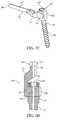
- FIG. 1Dis a cross-sectional drawing of a screw assembly.
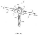
- FIG. 1Eis a drawing of a screw assembly.
- FIGS. 2A and 2Bare cross-sectional drawings of a screw assembly.
- FIG. 2Cis a drawing of a screw assembly showing a spherical-shaped collet-type connection between two arms and a cross-sectional view of a base.
- FIG. 2Dis a cross-sectional drawing of a screw assembly showing a spherical-shaped collet-type connection between two arms.
- FIG. 3Ais a drawing of a support assembly showing a screw assembly having one arm and a base attached to a support structure.
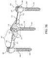
- FIG. 3Bis a drawing of a support assembly showing a screw assembly having two arms and a base attached to two support structures.
- FIG. 4is a drawing showing a support assembly implanted into the pedicles of the vertebrae of a spine.
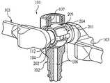
- a screw assembly 101including a base 102 and one or more arms 103 in a single unit.
- the arm 103 and base 102 of the screw assembly 101are coupled by an interconnection means.
- the base 102 of the screw assembly 101is configured for attachment to a structure (e.g., a bone) and the arm 103 is configured for attachment to a support structure (described in detail below).
- a screw assembly 101 having one or more arms 103is attached to one or more support structures to form a support assembly 301 (see FIGS. 3A and 3B ).
- the support assembly 301can be used for temporary or permanent implantation.
- the screw assembly 101 interconnection meanscan facilitate free-rotational (or multiaxial) movement of an arm 103 in relation to the base 102 .
- the interconnection meanscan be selected from any number of means including but not limited to: a hinge means, a collet means, and a pin.
- the interconnection meanscomprises a receiver end 112 disposed within a receiver 202 of a base 102 .
- the arm 103can have a substantially spherical-shaped receiver end 112 connected to a complementary-shaped receiver 202 in the base head 104 .
- the base head 104can be closed or open (e.g. open-saddle as shown in FIG. 1A ).
- the free-rotational arm 103 movement facilitated by the interconnection meansis substantially a cone-shaped range of movement having an axis about which such movement is centered (“cone axis” hereinafter).
- the implementation as shown in FIGS. 1A and 1Bcan be used to provide support to a structure in a patient (e.g. a spine having a series of vertebrae).
- a structure supportedis a spine, and the spine includes a long axis (“spinal axis” hereinafter)
- the screw assembly 101can provide support to the spine substantially collinearly with the spinal axis.
- the cone axis of movement of the arm 103 of the screw assembly 101can optionally be disposed so that the cone axis is substantially collinear with the spinal axis. This arrangement provides a degree of adjustability when positioning the arm 103 and base 102 of the screw assembly 101 in relation to the structure being supported (e.g. a series of vertebrae).
- the three points of attachment to the three vertebraecan be substantially linear.
- the three points of attachmentare not necessarily substantially linear.
- the interconnection meanscomprises one or more receiver end(s) 112 of one or more arm(s) 103 disposed within a base head 104 of a base 102 .
- the interconnection meanscan facilitate movement between the arm 103 and the base 102 , such that the arm 103 is positionable in a first position that is parallel to a long axis of the base 102 (shown in FIGS. 1D , 2 B, and 2 D) and positionable in a second position that is perpendicular to the long axis of the base 102 (shown in FIGS. 1C and 1E ).
- the screw assembly 101 interconnection meanscan facilitate free-rotational (or multiaxial) movement of an arm 103 in relation to the base 102 .
- the free-rotational movement of the arm 103can be substantially a cone-shaped range of movement having a cone axis.
- the implementation as shown in FIGS. 1C and 1Ecan be used to provide support to a structure in a patient (e.g. a spine having a series of vertebrae).
- the present implementationcan provide support to the spine substantially collinearly with the spinal axis.
- an implementation wherein support is provided substantially collinearly with the spinal axiscan include a cone axis of movement of the arm 103 of the screw assembly 101 disposed so that the cone axis is substantially perpendicular with the spinal axis.
- This arrangementprovides a similar degree of arm 103 adjustability and advantages as discussed above for the implementation shown in FIGS. 1C and 1E .
- the screw assembly 101can be made of materials that are durable and that can be implanted in a body, including titanium, stainless steel, carbon fiber, etc. In one implementation, the screw assembly 101 is made of titanium. In another implementation the screw assembly 101 is made of a biocompatible material, a reabsorbable material, or a combination of any of the foregoing materials.
- the dimensions of the screw assembly 101vary with the application. In general, in implementations as shown in FIGS. 1C and 1E , wherein the arm 103 is positionable in a first position that is substantially parallel to the long axis of the base 102 , the length of the screw assembly 101 is from substantially 20 to 1,000 millimeters. In one implementation, the length is substantially between 50 and 400 millimeters.
- the screw assembly 101is sized for applications involving support of multiples levels of the posterior of the spine (see FIG. 4 ).
- the length of the base 102is from substantially 20 to 100 millimeters and the length of the one or more arms 103 is from substantially 20 to 600 millimeters.
- the length of the base 102 and the length of the arm 103are each from substantially between 20 and 600 millimeters.
- the combined length of the base 102 and the arm 103is sized for applications involving support of multiple levels of the posterior of the spine (see FIG. 4 ).
- the screw assembly 101includes a longitudinal aperture 106 .
- the longitudinal aperture 106traverses the length of the screw assembly 101 , and provides an aperture for the passage of instruments, tools, and guides (e.g. a K-wire) when the arm 103 is positioned in a first position that is parallel to a long axis of the base 102 (see FIGS. 1D , 2 B, and 2 D).
- the base 102 of the screw assembly 101is comprised of a base head 104 and an anchor 105 .
- the anchor 105can be a screw, staple, hook, or nail, and can be of a type typically used for bone anchoring.
- the anchor 105is a screw of a type for insertion into a pedicle of a vertebra (see FIGS. 1A-1C , 1 E, 3 A- 3 B and 4 ).
- the interconnection means for coupling the base to the armsis comprised of the base head 104 .
- the base head 104can include a receiver 202 for receiving the receiver ends 112 of the screw assembly arms 103 .
- the base head 104is configured for hinged attachment of one or more screw assembly arms 103 using a hinge means (not shown). Such a means for connecting the base head 104 and the one or more screw assembly arms 103 is disclosed in U.S. application Ser. No. 10/825,962, filed Apr. 16, 2004, which is incorporated herein by reference in its entirety.
- the base head 104can include a locking means. As shown in FIGS. 1A-1D and 2 B- 2 D, the locking means can be a setscrew 107 .
- the base head 104can be designed to include an open-saddle (see FIGS. 1A and 1B ) or closed configuration (see FIGS. 1C-1E ) for accommodating the locking means (e.g. a setscrew 107 ).
- the locking meansis a setscrew 107 , which secures the base 102 and the one or more arms 103 of the screw assembly 101 together.
- a screw assembly 101including a base 102 , one or more arms 103 and a locking means can be pre-assembled for delivery to a structure.
- the screw assembly 101can be delivered as separate pieces for assembly at the site of a structure.
- tightening the setscrew 107can effect locking of one or more arms 103 into a position in relation to the base 102 .
- the setscrew 107can be tightened to effect locking of the one or more arms 103 in the second position.
- a cam(not shown) can be substituted for the setscrew 107 .
- the setscrew 107can be tightened to effect locking of the arm 103 into a position.
- the arm 103can have a substantially spherical-shaped receiver end 112 connected to a complementary-shaped receiver 202 in the base head 104 .
- the base head 104can be closed or open (e.g. open-saddle as shown in FIG. 1A ). Tightening the setscrew 107 can create a load that compresses the receiver end 112 of the arm 103 against the receiver 202 to effect locking of the arm 103 into a position. As shown in FIG.
- the receiver 202can be a substantially spherical collet-type receiver.
- tightening the setscrew 107creates a load that compresses the receiver end 201 of the arm 103 against the receiver 202 , thereby deflecting one or more deformable fingers 204 around the receiver end 112 to effect locking of the arm 103 into a position (see FIG. 2C ).
- a first arm 103can include a substantially spherical collet-type receiver end 201 and the second arm can include a receiver end 112 configured to interconnect within the receiver end 201 (see FIGS. 2C and 2D ). As shown in FIG. 1B , wherein two arms 103 are connected to the base 102 , the setscrew 107 can be tightened to effect locking of both arms 103 into a position.
- a first arm 103can include a substantially spherical collet-type receiver end 201 and the second arm can include a receiver end 112 configured to interconnect within the receiver end 201 (see FIGS. 2C and 2D ). As shown in FIG.
- tightening the setscrew 107can create a load that compresses the receiver end 201 of the first arm 103 against the receiver end 112 of the second arm 103 , thereby deflecting one or more deformable fingers 204 of the receiver end 201 around the receiver end 112 of the second arm 103 to effect simultaneous locking of both arms 103 into a position.
- the receiver end 201 of the first arm 103 and the receiver end 112 of the second arm 103can also be configured to provide for step-wise locking of each arm 103 into a position in relation to the base head 104 .
- the receiver end 201 of the first armcan be configured such that initial tightening creates a load that compresses the receiver end 112 against the base head receiver 202 to effect locking of the first arm 103 into a position without affecting the free rotational movement of the second arm 103 .
- the increased load createdthereby can compresses the receiver end 201 of the first arm 103 against the receiver end 112 of the second arm 103 , thereby deflecting one or more deformable fingers 204 of the receiver end 201 around the receiver end 112 of the second arm 103 to effect locking of the second arm 103 into a position.
- the setscrew 107can be tightened to effect locking of a single arm 103 having a cylindrical shaped receiver end 112 , by creating a load that compresses the receiver end 112 of the arm 103 against the complementary-shaped receiver 202 .
- the setscrew 107can be tightened to effect locking of two arms 103 , wherein the first arm 103 includes a substantially cylindrical collet-type receiver end 201 and the second arm 103 (not shown) includes a receiver end 112 configured to interconnect within the collet-type receiver end 201 .
- tightening the setscrew 107creates a load that compresses the substantially cylindrical collet-type receiver end 201 of the first arm 103 against the receiver 202 (see FIG. 2B ), thereby deflecting one or more deformable fingers 204 (not shown) around the receiver end 112 of the second arm 103 to effect locking of both arms 103 into a position.
- the setscrew 107can be tightened to effect locking of two arms 103 , wherein the first arm 103 includes a substantially spherical collet-type receiver end 201 and the second arm 103 includes a receiver end 112 configured to interconnect within the collet-type receiver end 201 .
- tightening the setscrew 107creates a load that compresses the substantially spherical collet-type receiver end 201 of the first arm 103 against the receiver 202 , thereby deflecting one or more deformable fingers 204 around the receiver end 112 of the second arm 103 to effect locking of both arms 103 into a position (see FIG. 2C ).
- the setscrew 107includes a setscrew aperture 115 .
- the setscrew aperture 115can be configured to substantially align with the longitudinal aperture 106 of the base 102 , thereby enabling through passage between the longitudinal aperture 106 of the arm 103 and base 102 (as discussed above).
- the one or more arms 103 of the screw assembly 101include a body 111 wherein the body 111 has an elongate shape and includes a connector end 108 for attachment to a support structure 109 , and a receiver end 112 .
- the elongate shape of the body 111 of the arm 103is a rod.
- the elongate shape of the body 111 of the arm 103is substantially a longitudinally split rod.
- the elongate shape of the body 111 of the arm 103is a shape configured for fitted interrelation between two or more arms 103 positioned in a first position that is substantially parallel to a long axis of the base 102 (not shown).
- the fitted interrelationcan be comprised of a longitudinally split rod shape.
- the elongate shape of the body 111 of the arm 103includes an offset section 113 .
- the offset section 113can be configured to provide a low-profile to the screw assembly 101 when the one or more arms 103 are positioned substantially parallel to a long axis of the base 102 (See FIGS. 1D and 2B ). Additionally, the offset section 113 can provide a linear alignment of the base 102 and the body 111 of the arm 103 when the arm 103 is positioned substantially parallel to a long axis of the base 102 (See FIGS. 1D and 2B ).
- the body 111 of the arm 103includes a longitudinal aperture 106 .
- the longitudinal aperture 106is a channel or groove running the length of the body 111 of the arm 103 (not shown).
- two interrelating arms 103can have longitudinal apertures 106 that align to form a single longitudinal aperture 106 when the arms 103 are interrelated.
- the longitudinal aperture 106 of the body 111 of the arm 103can be coaxially aligned with the longitudinal aperture 106 of the base 102 of the screw assembly 101 .
- the longitudinal aperture 106traverses the length of the screw assembly 101 , and provides an aperture for the passage of instruments, tools, and guides (e.g. a K-wire)
- the receiver ends 112 of the one or more arms 103can include a hinge means for hinged interconnection with the base head 104 (not shown).
- a locking meanscan be provided whereby after deployment, the one or more arms 103 are lockable into a position substantially perpendicular to the long axis of the base 103 .
- An example of such a locking meanscan be a one-way ratchet configuration (not shown).
- the receiver end 112 of a single arm 103can be cylindrical shape for interconnection within the receiver 202 of the base head 104 .
- the receiver 202can be an aperture in which the receiver end 112 of the arm 103 is received.
- the receiver ends 112 of two arms 103can be interconnecting and disposed within the base head 104 .
- the receiver ends 112can interconnect by way of a collet-type design.
- the two interconnecting receiver ends 112can have a cylindrical-shaped collet-type design including: a first collet-type receiver end 201 having a substantially cylindrical recess, one or more relief cuts 203 and one or more deformable fingers 204 , and; a second solid cylindrical-shaped receiver end 112 configured for fitting into the cylindrical recess of the collet-type receiver end 201 (not shown).
- the two interconnecting receiver ends 112can have a spherical-shaped collet-type design including: a first collet-type receiver end 201 having a substantially spherical recess, one or more relief cuts 203 and one or more deformable fingers 204 , and; a second solid spherical-shaped receiver end 112 configured for fitting into the first collet-type receiver end 201 .
- the respective receiver ends 112can include a longitudinal aperture 106 passing through the interconnected receiver ends 112 .
- a longitudinal aperture 106can be configured to provide coaxial alignment with the longitudinal aperture 106 of the base 102 , when the arms 103 are positioned substantially parallel to the long axis of the base 102 (see FIGS. 2B and 2D ).
- each support structure 109is comprised of an anchor 105 , an aperture 110 , and a locking means (see FIGS. 3A and 3B ).
- the one or more support structures 109can be made of materials that are durable and that can be implanted in a body, including titanium, stainless steel, carbon fiber, etc.
- the one or more support structures 109are made of titanium.
- the one or more support structures 109are made of a biocompatible material, a reabsorbable material, or a combination of any of the foregoing materials.
- each support structure 109is configured for attachment to a structure in a patient (e.g. bone).
- the locking means for the one or more support structures 109can be a setscrew 107 .
- the locking meanscan be a cam (not shown).
- two support structures 109can be attached to a screw assembly 101 to provide a support assembly 301 that can be implanted into the pedicles 403 of vertebra 402 in a spine 401 to effect support of the spine 401 .
- a single support structure 109can be attached to a screw assembly 101 to provide a support assembly 301 that can be implanted into the pedicles 403 of vertebra 402 in a spine 401 to effect support of the spine 401 .
- a method of using the invention to support the spine 401includes the steps of: 1) delivering to bone a screw assembly 101 having one or more arms 103 , a base 102 and an interconnection means (e.g.
- the one or more flanking support structures 109can be delivered, for example, to bone including one or more vertebral bodies on one or both sides of a vertebral body to which the screw assembly 101 is delivered.
- the one or more flanking support structures 109are delivered to vertebral bodies adjacent to the vertebral body to which the screw assembly 101 is delivered. In another implementation, one or more of the flanking support structures 109 are delivered to vertebral bodies distal to the adjacent-most vertebral body.
- the method of supporting the spinecan also be used in conjunction with a kyphoplasty procedure.
- Kyphoplastyis a percutaneous technique involving the use of an expandable structure, such as a balloon catheter, to create a cavity or void within the vertebral body, followed by filling the cavity with a bone substitute to form an “internal cast”.
- the bone substitutecould be any appropriate filling materials used in orthopedic surgery, including but not limited to, allograft or autograft tissue, hydroxyapatite, epoxy, PMMA bone cement or synthetic bone substitutes, medical grade plaster of Paris or calcium phosphate or calcium sulfate cements. Methods and instruments suitable for such treatment are more fully described in U.S. Pat. Nos.
- Kyphoplastycan be used to reduce vertebral compression fractures and to move bone with precision, thus restoring as close to normal the pre-fracture anatomy of the vertebral body.
- Vertebral compression fractures caused by traumahave traditionally been treated with open reduction, internal fixation stabilization hardware and fusion techniques using a posterior approach.
- the stabilization hardwareis used to offload the fractured vertebral body and to stop motion across the disk so that bone graft can fuse one vertebral body to the next and the stabilization hardware usually becomes a permanent implant.
- the stabilization hardwaremay be designed to facilitate easy removal after fusion has occurred.
- Stabilization hardwarecan take many forms, including those described herein.
Landscapes
- Health & Medical Sciences (AREA)
- Orthopedic Medicine & Surgery (AREA)
- Life Sciences & Earth Sciences (AREA)
- Neurology (AREA)
- Surgery (AREA)
- Heart & Thoracic Surgery (AREA)
- Engineering & Computer Science (AREA)
- Biomedical Technology (AREA)
- Nuclear Medicine, Radiotherapy & Molecular Imaging (AREA)
- Medical Informatics (AREA)
- Molecular Biology (AREA)
- Animal Behavior & Ethology (AREA)
- General Health & Medical Sciences (AREA)
- Public Health (AREA)
- Veterinary Medicine (AREA)
- Surgical Instruments (AREA)
Abstract
Description
Claims (20)
Priority Applications (7)
| Application Number | Priority Date | Filing Date | Title |
|---|---|---|---|
| US11/027,501US7811311B2 (en) | 2004-12-30 | 2004-12-30 | Screw with deployable interlaced dual rods |
| EP05735206AEP1740112A1 (en) | 2004-04-16 | 2005-04-15 | Screw assembly |
| JP2007508524AJP2007532258A (en) | 2004-04-16 | 2005-04-15 | Screw assembly |
| CA002562744ACA2562744A1 (en) | 2004-04-16 | 2005-04-15 | Screw assembly |
| CN2005800195865ACN1997321B (en) | 2004-04-16 | 2005-04-15 | Screw assembly |
| AU2005237459AAU2005237459A1 (en) | 2004-04-16 | 2005-04-15 | Screw assembly |
| PCT/US2005/012657WO2005104970A1 (en) | 2004-04-16 | 2005-04-15 | Screw assembly |
Applications Claiming Priority (1)
| Application Number | Priority Date | Filing Date | Title |
|---|---|---|---|
| US11/027,501US7811311B2 (en) | 2004-12-30 | 2004-12-30 | Screw with deployable interlaced dual rods |
Publications (2)
| Publication Number | Publication Date |
|---|---|
| US20060149237A1 US20060149237A1 (en) | 2006-07-06 |
| US7811311B2true US7811311B2 (en) | 2010-10-12 |
Family
ID=36641606
Family Applications (1)
| Application Number | Title | Priority Date | Filing Date |
|---|---|---|---|
| US11/027,501Active2027-03-10US7811311B2 (en) | 2004-04-16 | 2004-12-30 | Screw with deployable interlaced dual rods |
Country Status (1)
| Country | Link |
|---|---|
| US (1) | US7811311B2 (en) |
Cited By (26)
| Publication number | Priority date | Publication date | Assignee | Title |
|---|---|---|---|---|
| US20080071275A1 (en)* | 2001-03-26 | 2008-03-20 | Nu Vasive, Inc. | Spinal alignment system and related methods |
| US20080114363A1 (en)* | 2006-11-14 | 2008-05-15 | Spinefrontier Lls | Multi-component k-wire |
| US20080300630A1 (en)* | 2007-05-31 | 2008-12-04 | Baat Holding B.V. | Medical device for positioning bone elements, in particular vertebrae, relative to each other, as well as a tool for the placement, part by part, of such a medical device |
| US8007518B2 (en) | 2008-02-26 | 2011-08-30 | Spartek Medical, Inc. | Load-sharing component having a deflectable post and method for dynamic stabilization of the spine |
| US8012181B2 (en) | 2008-02-26 | 2011-09-06 | Spartek Medical, Inc. | Modular in-line deflection rod and bone anchor system and method for dynamic stabilization of the spine |
| US8016861B2 (en) | 2008-02-26 | 2011-09-13 | Spartek Medical, Inc. | Versatile polyaxial connector assembly and method for dynamic stabilization of the spine |
| US8021396B2 (en) | 2007-06-05 | 2011-09-20 | Spartek Medical, Inc. | Configurable dynamic spinal rod and method for dynamic stabilization of the spine |
| US20110251646A1 (en)* | 2008-12-10 | 2011-10-13 | Concept Spine Ltd | Surgical device for correction of spinal deformities |
| US8048115B2 (en) | 2007-06-05 | 2011-11-01 | Spartek Medical, Inc. | Surgical tool and method for implantation of a dynamic bone anchor |
| US8057515B2 (en) | 2008-02-26 | 2011-11-15 | Spartek Medical, Inc. | Load-sharing anchor having a deflectable post and centering spring and method for dynamic stabilization of the spine |
| US8083772B2 (en) | 2007-06-05 | 2011-12-27 | Spartek Medical, Inc. | Dynamic spinal rod assembly and method for dynamic stabilization of the spine |
| US8083775B2 (en) | 2008-02-26 | 2011-12-27 | Spartek Medical, Inc. | Load-sharing bone anchor having a natural center of rotation and method for dynamic stabilization of the spine |
| US8092501B2 (en) | 2007-06-05 | 2012-01-10 | Spartek Medical, Inc. | Dynamic spinal rod and method for dynamic stabilization of the spine |
| US8097024B2 (en) | 2008-02-26 | 2012-01-17 | Spartek Medical, Inc. | Load-sharing bone anchor having a deflectable post and method for stabilization of the spine |
| US8114134B2 (en) | 2007-06-05 | 2012-02-14 | Spartek Medical, Inc. | Spinal prosthesis having a three bar linkage for motion preservation and dynamic stabilization of the spine |
| US8211155B2 (en) | 2008-02-26 | 2012-07-03 | Spartek Medical, Inc. | Load-sharing bone anchor having a durable compliant member and method for dynamic stabilization of the spine |
| US8257397B2 (en) | 2009-12-02 | 2012-09-04 | Spartek Medical, Inc. | Low profile spinal prosthesis incorporating a bone anchor having a deflectable post and a compound spinal rod |
| US8267979B2 (en) | 2008-02-26 | 2012-09-18 | Spartek Medical, Inc. | Load-sharing bone anchor having a deflectable post and axial spring and method for dynamic stabilization of the spine |
| US8317836B2 (en) | 2007-06-05 | 2012-11-27 | Spartek Medical, Inc. | Bone anchor for receiving a rod for stabilization and motion preservation spinal implantation system and method |
| US8333792B2 (en) | 2008-02-26 | 2012-12-18 | Spartek Medical, Inc. | Load-sharing bone anchor having a deflectable post and method for dynamic stabilization of the spine |
| US8337536B2 (en) | 2008-02-26 | 2012-12-25 | Spartek Medical, Inc. | Load-sharing bone anchor having a deflectable post with a compliant ring and method for stabilization of the spine |
| US8430916B1 (en) | 2012-02-07 | 2013-04-30 | Spartek Medical, Inc. | Spinal rod connectors, methods of use, and spinal prosthesis incorporating spinal rod connectors |
| US8518085B2 (en) | 2010-06-10 | 2013-08-27 | Spartek Medical, Inc. | Adaptive spinal rod and methods for stabilization of the spine |
| EP3751574A2 (en) | 2014-06-25 | 2020-12-16 | Canary Medical Inc. | Devices, systems and methods for using and monitoring orthopedic hardware |
| US12138029B2 (en) | 2014-06-25 | 2024-11-12 | Canary Medical Switzerland Ag | Devices, systems and methods for using and monitoring spinal implants |
| EP4501218A2 (en) | 2014-09-17 | 2025-02-05 | Canary Medical Inc. | Devices, systems and methods for using and monitoring medical devices |
Families Citing this family (63)
| Publication number | Priority date | Publication date | Assignee | Title |
|---|---|---|---|---|
| AU2004212942A1 (en) | 2003-02-14 | 2004-09-02 | Depuy Spine, Inc. | In-situ formed intervertebral fusion device |
| US7476240B2 (en)* | 2004-02-06 | 2009-01-13 | Depuy Spine, Inc. | Devices and methods for inserting a spinal fixation element |
| US7789899B2 (en)* | 2004-12-30 | 2010-09-07 | Warsaw Orthopedic, Inc. | Bone anchorage screw with built-in hinged plate |
| US7524323B2 (en)* | 2004-04-16 | 2009-04-28 | Kyphon Sarl | Subcutaneous support |
| US7618418B2 (en)* | 2004-04-16 | 2009-11-17 | Kyphon Sarl | Plate system for minimally invasive support of the spine |
| US7648520B2 (en)* | 2004-04-16 | 2010-01-19 | Kyphon Sarl | Pedicle screw assembly |
| DE202004020396U1 (en) | 2004-08-12 | 2005-07-07 | Columbus Trading-Partners Pos und Brendel GbR (vertretungsberechtigte Gesellschafter Karin Brendel, 95503 Hummeltal und Bohumila Pos, 95445 Bayreuth) | Child seat for motor vehicles |
| US8366773B2 (en) | 2005-08-16 | 2013-02-05 | Benvenue Medical, Inc. | Apparatus and method for treating bone |
| AU2006279558B2 (en) | 2005-08-16 | 2012-05-17 | Izi Medical Products, Llc | Spinal tissue distraction devices |
| WO2008103781A2 (en) | 2007-02-21 | 2008-08-28 | Benvenue Medical, Inc. | Devices for treating the spine |
| GB0521582D0 (en) | 2005-10-22 | 2005-11-30 | Depuy Int Ltd | An implant for supporting a spinal column |
| GB0600662D0 (en) | 2006-01-13 | 2006-02-22 | Depuy Int Ltd | Spinal support rod kit |
| US8348952B2 (en) | 2006-01-26 | 2013-01-08 | Depuy International Ltd. | System and method for cooling a spinal correction device comprising a shape memory material for corrective spinal surgery |
| US7588593B2 (en)* | 2006-04-18 | 2009-09-15 | International Spinal Innovations, Llc | Pedicle screw with vertical adjustment |
| US20080058808A1 (en) | 2006-06-14 | 2008-03-06 | Spartek Medical, Inc. | Implant system and method to treat degenerative disorders of the spine |
| US20080058805A1 (en)* | 2006-08-28 | 2008-03-06 | Microdexterity Systems, Inc. | Spinal fusion implant |
| US20080071274A1 (en)* | 2006-09-15 | 2008-03-20 | Ensign Michael D | Percutaneous Screw Assembly and Placement Method |
| WO2008070863A2 (en) | 2006-12-07 | 2008-06-12 | Interventional Spine, Inc. | Intervertebral implant |
| US20080161853A1 (en) | 2006-12-28 | 2008-07-03 | Depuy Spine, Inc. | Spine stabilization system with dynamic screw |
| EP2124778B1 (en) | 2007-02-21 | 2019-09-25 | Benvenue Medical, Inc. | Devices for treating the spine |
| US8016832B2 (en) | 2007-05-02 | 2011-09-13 | Zimmer Spine, Inc. | Installation systems for spinal stabilization system and related methods |
| US8109970B2 (en) | 2007-06-05 | 2012-02-07 | Spartek Medical, Inc. | Deflection rod system with a deflection contouring shield for a spine implant and method |
| US8052722B2 (en) | 2007-06-05 | 2011-11-08 | Spartek Medical, Inc. | Dual deflection rod system for a dynamic stabilization and motion preservation spinal implantation system and method |
| US8900307B2 (en) | 2007-06-26 | 2014-12-02 | DePuy Synthes Products, LLC | Highly lordosed fusion cage |
| JP2010536533A (en)* | 2007-08-24 | 2010-12-02 | スピナル エレメンツ,インク. | Loop rod spinal fixation device |
| GB0720762D0 (en) | 2007-10-24 | 2007-12-05 | Depuy Spine Sorl | Assembly for orthopaedic surgery |
| EP2237748B1 (en) | 2008-01-17 | 2012-09-05 | Synthes GmbH | An expandable intervertebral implant |
| US8936641B2 (en) | 2008-04-05 | 2015-01-20 | DePuy Synthes Products, LLC | Expandable intervertebral implant |
| USD607103S1 (en)* | 2008-10-22 | 2009-12-29 | Ulrich Gmbh & Co. Kg | Medical implant |
| US8535327B2 (en) | 2009-03-17 | 2013-09-17 | Benvenue Medical, Inc. | Delivery apparatus for use with implantable medical devices |
| US9526620B2 (en) | 2009-03-30 | 2016-12-27 | DePuy Synthes Products, Inc. | Zero profile spinal fusion cage |
| US9827013B2 (en) | 2009-12-08 | 2017-11-28 | Concept Spine Ltd. | Surgical device for correction of spinal deformities |
| US9393129B2 (en) | 2009-12-10 | 2016-07-19 | DePuy Synthes Products, Inc. | Bellows-like expandable interbody fusion cage |
| US8979860B2 (en) | 2010-06-24 | 2015-03-17 | DePuy Synthes Products. LLC | Enhanced cage insertion device |
| US9907560B2 (en) | 2010-06-24 | 2018-03-06 | DePuy Synthes Products, Inc. | Flexible vertebral body shavers |
| US8623091B2 (en) | 2010-06-29 | 2014-01-07 | DePuy Synthes Products, LLC | Distractible intervertebral implant |
| WO2012031000A1 (en) | 2010-09-03 | 2012-03-08 | International Spinal Innovations, Llc | Polyaxial vertebral anchor assembly with vertical adjustment and split lock |
| US9402732B2 (en) | 2010-10-11 | 2016-08-02 | DePuy Synthes Products, Inc. | Expandable interspinous process spacer implant |
| US20120116458A1 (en)* | 2010-11-08 | 2012-05-10 | Warsaw Orthopedic, Inc. | Modular pivotable screw assembly and method |
| US8814873B2 (en) | 2011-06-24 | 2014-08-26 | Benvenue Medical, Inc. | Devices and methods for treating bone tissue |
| US20130110123A1 (en)* | 2011-10-26 | 2013-05-02 | Warsaw Orthopedic, Inc. | Devices and methods to position an anchor during a surgical procedure |
| US9622786B2 (en)* | 2012-01-09 | 2017-04-18 | Apifix Ltd. | Spinal cage |
| USD741485S1 (en)* | 2012-06-07 | 2015-10-20 | Southern Implants (Pty) Ltd | Bone distractor |
| US9717601B2 (en) | 2013-02-28 | 2017-08-01 | DePuy Synthes Products, Inc. | Expandable intervertebral implant, system, kit and method |
| US9522070B2 (en) | 2013-03-07 | 2016-12-20 | Interventional Spine, Inc. | Intervertebral implant |
| US10085783B2 (en) | 2013-03-14 | 2018-10-02 | Izi Medical Products, Llc | Devices and methods for treating bone tissue |
| EP3193755B1 (en) | 2014-09-19 | 2022-02-09 | In Queue Innovations, LLC | Fusion systems of assembly and use |
| US11426290B2 (en) | 2015-03-06 | 2022-08-30 | DePuy Synthes Products, Inc. | Expandable intervertebral implant, system, kit and method |
| DE102015010741A1 (en)* | 2015-03-19 | 2016-09-22 | Ngmedical Gmbh | Polyaxial pedicle screw with spherical segment-shaped head |
| EP3474784A2 (en) | 2016-06-28 | 2019-05-01 | Eit Emerging Implant Technologies GmbH | Expandable and angularly adjustable intervertebral cages with articulating joint |
| US11510788B2 (en) | 2016-06-28 | 2022-11-29 | Eit Emerging Implant Technologies Gmbh | Expandable, angularly adjustable intervertebral cages |
| US10413330B2 (en)* | 2016-08-09 | 2019-09-17 | Warsaw Orthopedic, Inc. | Spinal implant system and method |
| US10888433B2 (en) | 2016-12-14 | 2021-01-12 | DePuy Synthes Products, Inc. | Intervertebral implant inserter and related methods |
| US10398563B2 (en) | 2017-05-08 | 2019-09-03 | Medos International Sarl | Expandable cage |
| US11344424B2 (en) | 2017-06-14 | 2022-05-31 | Medos International Sarl | Expandable intervertebral implant and related methods |
| US10940016B2 (en) | 2017-07-05 | 2021-03-09 | Medos International Sarl | Expandable intervertebral fusion cage |
| US11446156B2 (en) | 2018-10-25 | 2022-09-20 | Medos International Sarl | Expandable intervertebral implant, inserter instrument, and related methods |
| US11712272B2 (en)* | 2018-12-18 | 2023-08-01 | Frank J. Schwab | Technologies for lines coupled to spines |
| US11426286B2 (en) | 2020-03-06 | 2022-08-30 | Eit Emerging Implant Technologies Gmbh | Expandable intervertebral implant |
| US12310629B2 (en) | 2021-02-10 | 2025-05-27 | Alphatec Spine, Inc. | Methods and devices for augmenting the spine |
| US11850160B2 (en) | 2021-03-26 | 2023-12-26 | Medos International Sarl | Expandable lordotic intervertebral fusion cage |
| US11752009B2 (en) | 2021-04-06 | 2023-09-12 | Medos International Sarl | Expandable intervertebral fusion cage |
| US12090064B2 (en) | 2022-03-01 | 2024-09-17 | Medos International Sarl | Stabilization members for expandable intervertebral implants, and related systems and methods |
Citations (99)
| Publication number | Priority date | Publication date | Assignee | Title |
|---|---|---|---|---|
| US3779240A (en) | 1972-03-31 | 1973-12-18 | S Kondo | Compression plate for osteosynthesis |
| US4493317A (en) | 1980-11-20 | 1985-01-15 | Synthes Ltd. (U.S.A.) | Surgical compression plate and drill guide |
| US4763644A (en) | 1984-02-28 | 1988-08-16 | Webb Peter J | Spinal fixation |
| US4805602A (en) | 1986-11-03 | 1989-02-21 | Danninger Medical Technology | Transpedicular screw and rod system |
| US4946458A (en) | 1986-04-25 | 1990-08-07 | Harms Juergen | Pedicle screw |
| US5005562A (en) | 1988-06-24 | 1991-04-09 | Societe De Fabrication De Material Orthopedique | Implant for spinal osteosynthesis device, in particular in traumatology |
| US5053036A (en) | 1987-11-03 | 1991-10-01 | Synthes (U.S.A.) | Point contact bone compression plate |
| US5057111A (en) | 1987-11-04 | 1991-10-15 | Park Joon B | Non-stress-shielding bone fracture healing device |
| US5129899A (en) | 1991-03-27 | 1992-07-14 | Smith & Nephew Richards Inc. | Bone fixation apparatus |
| US5129388A (en) | 1989-02-09 | 1992-07-14 | Vignaud Jean Louis | Device for supporting the spinal column |
| US5147361A (en) | 1989-11-29 | 1992-09-15 | Asahi Kogaku Kogyo Kabushiki Kaisha | Vertebral connecting plate |
| US5151103A (en) | 1987-11-03 | 1992-09-29 | Synthes (U.S.A.) | Point contact bone compression plate |
| US5171279A (en) | 1992-03-17 | 1992-12-15 | Danek Medical | Method for subcutaneous suprafascial pedicular internal fixation |
| US5176679A (en)* | 1991-09-23 | 1993-01-05 | Lin Chih I | Vertebral locking and retrieving system |
| US5176678A (en) | 1991-03-14 | 1993-01-05 | Tsou Paul M | Orthopaedic device with angularly adjustable anchor attachments to the vertebrae |
| US5180381A (en) | 1991-09-24 | 1993-01-19 | Aust Gilbert M | Anterior lumbar/cervical bicortical compression plate |
| US5207678A (en) | 1989-07-20 | 1993-05-04 | Prufer | Pedicle screw and receiver member therefore |
| US5234431A (en) | 1991-04-03 | 1993-08-10 | Waldemar Link Gmbh & Co. | Bone plate arrangement |
| US5246442A (en) | 1991-12-31 | 1993-09-21 | Danek Medical, Inc. | Spinal hook |
| US5253406A (en) | 1992-11-17 | 1993-10-19 | Lisle Corporation | Brake clip tool |
| US5261909A (en) | 1992-02-18 | 1993-11-16 | Danek Medical, Inc. | Variable angle screw for spinal implant system |
| US5269784A (en) | 1991-12-10 | 1993-12-14 | Synthes (U.S.A.) | Screw nut for plate osteosynthesis |
| US5290288A (en) | 1990-02-08 | 1994-03-01 | Vignaud Jean Louis | Multi-function device for the osteosynthesis of rachis |
| DE9402695U1 (en) | 1994-02-18 | 1994-04-14 | Kernforschungszentrum Karlsruhe Gmbh, 76133 Karlsruhe | Implant |
| US5324290A (en) | 1992-09-24 | 1994-06-28 | Danek Medical, Inc. | Anterior thoracolumbar plate |
| US5360431A (en) | 1990-04-26 | 1994-11-01 | Cross Medical Products | Transpedicular screw system and method of use |
| US5395371A (en) | 1991-07-15 | 1995-03-07 | Danek Group, Inc. | Spinal fixation system |
| US5429639A (en) | 1993-05-17 | 1995-07-04 | Tornier S.A. | Spine fixator for holding a vertebral column |
| US5443467A (en) | 1993-03-10 | 1995-08-22 | Biedermann Motech Gmbh | Bone screw |
| US5466238A (en)* | 1993-08-27 | 1995-11-14 | Lin; Chih-I | Vertebral locking and retrieving system having a fixation crossbar |
| US5466237A (en) | 1993-11-19 | 1995-11-14 | Cross Medical Products, Inc. | Variable locking stabilizer anchor seat and screw |
| US5474551A (en) | 1994-11-18 | 1995-12-12 | Smith & Nephew Richards, Inc. | Universal coupler for spinal fixation |
| US5476464A (en) | 1993-02-25 | 1995-12-19 | Howmedica Gmbh | Device for setting a spine |
| US5480401A (en) | 1993-02-17 | 1996-01-02 | Psi | Extra-discal inter-vertebral prosthesis for controlling the variations of the inter-vertebral distance by means of a double damper |
| US5480440A (en) | 1991-08-15 | 1996-01-02 | Smith & Nephew Richards, Inc. | Open surgical technique for vertebral fixation with subcutaneous fixators positioned between the skin and the lumbar fascia of a patient |
| US5499983A (en)* | 1994-02-23 | 1996-03-19 | Smith & Nephew Richards, Inc. | Variable angle spinal screw |
| US5501684A (en) | 1992-06-25 | 1996-03-26 | Synthes (U.S.A.) | Osteosynthetic fixation device |
| US5520690A (en) | 1995-04-13 | 1996-05-28 | Errico; Joseph P. | Anterior spinal polyaxial locking screw plate assembly |
| US5549608A (en) | 1995-07-13 | 1996-08-27 | Fastenetix, L.L.C. | Advanced polyaxial locking screw and coupling element device for use with rod fixation apparatus |
| US5554157A (en) | 1995-07-13 | 1996-09-10 | Fastenetix, L.L.C. | Rod securing polyaxial locking screw and coupling element assembly |
| US5575792A (en) | 1995-07-14 | 1996-11-19 | Fastenetix, L.L.C. | Extending hook and polyaxial coupling element device for use with top loading rod fixation devices |
| US5578033A (en) | 1995-07-13 | 1996-11-26 | Fastenetix, L.L.C. | Advanced polyaxial locking hook and coupling element device for use with side loading rod fixation devices |
| US5584834A (en) | 1995-07-13 | 1996-12-17 | Fastenetix, L.L.C. | Polyaxial locking screw and coupling element assembly for use with side loading rod fixation apparatus |
| US5586984A (en) | 1995-07-13 | 1996-12-24 | Fastenetix, L.L.C. | Polyaxial locking screw and coupling element assembly for use with rod fixation apparatus |
| US5591166A (en) | 1995-03-27 | 1997-01-07 | Smith & Nephew Richards, Inc. | Multi angle bone bolt |
| US5609593A (en) | 1995-07-13 | 1997-03-11 | Fastenetix, Llc | Advanced polyaxial locking hook and coupling element device for use with top loading rod fixation devices |
| US5649926A (en) | 1994-07-14 | 1997-07-22 | Advanced Spine Fixation Systems, Inc. | Spinal segmental reduction derotational fixation system |
| US5669911A (en) | 1995-04-13 | 1997-09-23 | Fastenetix, L.L.C. | Polyaxial pedicle screw |
| US5672176A (en) | 1995-03-15 | 1997-09-30 | Biedermann; Lutz | Anchoring member |
| US5733286A (en) | 1997-02-12 | 1998-03-31 | Third Millennium Engineering, Llc | Rod securing polyaxial locking screw and coupling element assembly |
| US5733285A (en) | 1995-07-13 | 1998-03-31 | Fastenetix, Llc | Polyaxial locking mechanism |
| US5876403A (en)* | 1996-09-06 | 1999-03-02 | Robert Reid Inc. | Bone-fixing devices |
| US5882350A (en) | 1995-04-13 | 1999-03-16 | Fastenetix, Llc | Polyaxial pedicle screw having a threaded and tapered compression locking mechanism |
| US5885286A (en) | 1996-09-24 | 1999-03-23 | Sdgi Holdings, Inc. | Multi-axial bone screw assembly |
| US5951553A (en) | 1997-07-14 | 1999-09-14 | Sdgi Holdings, Inc. | Methods and apparatus for fusionless treatment of spinal deformities |
| US5964988A (en) | 1995-03-15 | 1999-10-12 | Avery Dennison Corporation | Web feeder with controlled electrostatic force and method |
| US5964761A (en) | 1997-07-15 | 1999-10-12 | Kambin; Parviz | Method and instruments for percutaneous arthroscopic disc removal, bone biopsy and fixation of vertebrae |
| FR2780631A1 (en) | 1998-07-06 | 2000-01-07 | Dimso Sa | SPINAL OSTEOSYNTHESIS DEVICE FOR ANTERIOR FIXATION WITH PLATE |
| US6022350A (en) | 1996-05-13 | 2000-02-08 | Stryker France S.A. | Bone fixing device, in particular for fixing to the sacrum during osteosynthesis of the backbone |
| US6030389A (en) | 1997-08-04 | 2000-02-29 | Spinal Concepts, Inc. | System and method for stabilizing the human spine with a bone plate |
| US6053917A (en) | 1996-09-24 | 2000-04-25 | Sdgi Holdings, Inc. | Multi-axial bone screw assembly |
| US6063090A (en) | 1996-12-12 | 2000-05-16 | Synthes (U.S.A.) | Device for connecting a longitudinal support to a pedicle screw |
| US6074391A (en) | 1997-06-16 | 2000-06-13 | Howmedica Gmbh | Receiving part for a retaining component of a vertebral column implant |
| US6077262A (en) | 1993-06-04 | 2000-06-20 | Synthes (U.S.A.) | Posterior spinal implant |
| US6090111A (en) | 1998-06-17 | 2000-07-18 | Surgical Dynamics, Inc. | Device for securing spinal rods |
| US6090110A (en) | 1992-03-02 | 2000-07-18 | Howmedica Gmbh | Apparatus for bracing vertebrae |
| US6113601A (en) | 1998-06-12 | 2000-09-05 | Bones Consulting, Llc | Polyaxial pedicle screw having a loosely coupled locking cap |
| WO2000054681A2 (en) | 1999-03-16 | 2000-09-21 | Societe De Fabrication De Materiel Orthopedique (Sofamor) | Spinal osteosynthesis instrumentation |
| US6231575B1 (en)* | 1998-08-27 | 2001-05-15 | Martin H. Krag | Spinal column retainer |
| US6280442B1 (en) | 1999-09-01 | 2001-08-28 | Sdgi Holdings, Inc. | Multi-axial bone screw assembly |
| US6296644B1 (en)* | 1998-08-26 | 2001-10-02 | Jean Saurat | Spinal instrumentation system with articulated modules |
| US6315779B1 (en) | 1999-04-16 | 2001-11-13 | Sdgi Holdings, Inc. | Multi-axial bone anchor system |
| US20020007183A1 (en) | 1998-07-06 | 2002-01-17 | Solco Surgical Instruments Co., Ltd. | Spine fixing apparatus |
| WO2002076315A1 (en) | 2001-03-26 | 2002-10-03 | Ferree Bret A | Spinal alignment apparatus and methods |
| US20020143332A1 (en)* | 1997-05-15 | 2002-10-03 | Chih-I Lin | Clamping connector for spinal fixation systems |
| US20030032957A1 (en) | 2001-08-13 | 2003-02-13 | Mckinley Laurence M. | Vertebral alignment and fixation assembly |
| US20030105460A1 (en) | 2000-03-15 | 2003-06-05 | Dennis Crandall | Multidirectional pivoting bone screw and fixation system |
| US20030114853A1 (en) | 2001-10-12 | 2003-06-19 | Ian Burgess | Polyaxial cross connector |
| US20030135210A1 (en) | 2002-01-14 | 2003-07-17 | Dixon Robert A. | Dynamized vertebral stabilized using an outrigger implant |
| US20040054371A1 (en)* | 2002-06-11 | 2004-03-18 | Michael Dierks | Bone screw |
| US20040087949A1 (en) | 2002-10-31 | 2004-05-06 | Bono Frank S. | Snap-in washers and assemblies thereof |
| US20040092931A1 (en) | 2000-11-07 | 2004-05-13 | Jean Taylor | Vertebral arthrodesis equipment |
| US6736817B2 (en) | 1999-12-17 | 2004-05-18 | Thomas N. Troxell | Transconnector for coupling spinal rods |
| US6755829B1 (en) | 2000-09-22 | 2004-06-29 | Depuy Acromed, Inc. | Lock cap anchor assembly for orthopaedic fixation |
| US20040127897A1 (en) | 2000-01-06 | 2004-07-01 | Jim Freid | System and method for stabilizing the human spine with a bone plate |
| WO2004064603A2 (en) | 2003-01-16 | 2004-08-05 | Triage Medical Inc. | Locking plate for bone anchors |
| WO2004093701A2 (en) | 2003-04-17 | 2004-11-04 | Sdgi Holdings, Inc. | Spinal fixation sytem and method |
| US20040225290A1 (en) | 2001-03-27 | 2004-11-11 | Nuvasive, Inc. | Hinged anterior thoracic/lumbar plate |
| US6858031B2 (en) | 1999-04-16 | 2005-02-22 | Sdgi Holdings, Inc. | Multi-axial bone anchor system |
| US20050049588A1 (en) | 2003-08-28 | 2005-03-03 | Jackson Roger P. | Polyaxial bone screw with split retainer ring |
| US6884241B2 (en) | 2001-09-04 | 2005-04-26 | Orthotec, Llc | Spinal assembly plate |
| US6887241B1 (en) | 2000-10-06 | 2005-05-03 | Spinal Concepts, Inc. | Adjustable transverse connector with cam activated engagers |
| US20050113927A1 (en)* | 2003-11-25 | 2005-05-26 | Malek Michel H. | Spinal stabilization systems |
| US20050215999A1 (en) | 2004-03-19 | 2005-09-29 | Depuy Spine, Inc. | Spinal fixation element and methods |
| US20050234456A1 (en) | 2004-04-16 | 2005-10-20 | Malandain Hugues F | Plate system for minimally invasive support of the spine |
| US20050234451A1 (en) | 2004-04-16 | 2005-10-20 | Markworth Aaron D | Pedicle screw assembly |
| US20050234452A1 (en) | 2004-04-16 | 2005-10-20 | Malandain Hugues F | Subcutaneous support |
| US20060149252A1 (en) | 2004-12-30 | 2006-07-06 | Markworth Aaron D | Bone anchorage screw with built-in hinged plate |
| US7220262B1 (en)* | 2001-03-16 | 2007-05-22 | Sdgi Holdings, Inc. | Spinal fixation system and related methods |
Family Cites Families (3)
| Publication number | Priority date | Publication date | Assignee | Title |
|---|---|---|---|---|
| US2780631A (en)* | 1956-05-04 | 1957-02-05 | Dow Chemical Co | Thiazolyl chloro-aliphatic amides |
| US6744829B1 (en)* | 2000-09-21 | 2004-06-01 | Koninklijke Philips Electronics N.V. | Calibration of a quadrature receiver |
| JP4713812B2 (en)* | 2002-09-30 | 2011-06-29 | 富士通株式会社 | Information processing apparatus, program, and information processing system |
- 2004
- 2004-12-30USUS11/027,501patent/US7811311B2/enactiveActive
Patent Citations (109)
| Publication number | Priority date | Publication date | Assignee | Title |
|---|---|---|---|---|
| US3779240A (en) | 1972-03-31 | 1973-12-18 | S Kondo | Compression plate for osteosynthesis |
| US4493317A (en) | 1980-11-20 | 1985-01-15 | Synthes Ltd. (U.S.A.) | Surgical compression plate and drill guide |
| US4763644A (en) | 1984-02-28 | 1988-08-16 | Webb Peter J | Spinal fixation |
| US4946458A (en) | 1986-04-25 | 1990-08-07 | Harms Juergen | Pedicle screw |
| US4805602A (en) | 1986-11-03 | 1989-02-21 | Danninger Medical Technology | Transpedicular screw and rod system |
| US5151103A (en) | 1987-11-03 | 1992-09-29 | Synthes (U.S.A.) | Point contact bone compression plate |
| US5053036A (en) | 1987-11-03 | 1991-10-01 | Synthes (U.S.A.) | Point contact bone compression plate |
| US5057111A (en) | 1987-11-04 | 1991-10-15 | Park Joon B | Non-stress-shielding bone fracture healing device |
| US5005562A (en) | 1988-06-24 | 1991-04-09 | Societe De Fabrication De Material Orthopedique | Implant for spinal osteosynthesis device, in particular in traumatology |
| US5129388A (en) | 1989-02-09 | 1992-07-14 | Vignaud Jean Louis | Device for supporting the spinal column |
| US5207678A (en) | 1989-07-20 | 1993-05-04 | Prufer | Pedicle screw and receiver member therefore |
| US5147361A (en) | 1989-11-29 | 1992-09-15 | Asahi Kogaku Kogyo Kabushiki Kaisha | Vertebral connecting plate |
| US5290288A (en) | 1990-02-08 | 1994-03-01 | Vignaud Jean Louis | Multi-function device for the osteosynthesis of rachis |
| US5474555A (en) | 1990-04-26 | 1995-12-12 | Cross Medical Products | Spinal implant system |
| US5360431A (en) | 1990-04-26 | 1994-11-01 | Cross Medical Products | Transpedicular screw system and method of use |
| US5176678A (en) | 1991-03-14 | 1993-01-05 | Tsou Paul M | Orthopaedic device with angularly adjustable anchor attachments to the vertebrae |
| US5129899A (en) | 1991-03-27 | 1992-07-14 | Smith & Nephew Richards Inc. | Bone fixation apparatus |
| US5234431A (en) | 1991-04-03 | 1993-08-10 | Waldemar Link Gmbh & Co. | Bone plate arrangement |
| US5395371A (en) | 1991-07-15 | 1995-03-07 | Danek Group, Inc. | Spinal fixation system |
| US5480440A (en) | 1991-08-15 | 1996-01-02 | Smith & Nephew Richards, Inc. | Open surgical technique for vertebral fixation with subcutaneous fixators positioned between the skin and the lumbar fascia of a patient |
| US5176679A (en)* | 1991-09-23 | 1993-01-05 | Lin Chih I | Vertebral locking and retrieving system |
| US5180381A (en) | 1991-09-24 | 1993-01-19 | Aust Gilbert M | Anterior lumbar/cervical bicortical compression plate |
| US5269784A (en) | 1991-12-10 | 1993-12-14 | Synthes (U.S.A.) | Screw nut for plate osteosynthesis |
| US5246442A (en) | 1991-12-31 | 1993-09-21 | Danek Medical, Inc. | Spinal hook |
| US5261909A (en) | 1992-02-18 | 1993-11-16 | Danek Medical, Inc. | Variable angle screw for spinal implant system |
| US6090110A (en) | 1992-03-02 | 2000-07-18 | Howmedica Gmbh | Apparatus for bracing vertebrae |
| US5171279A (en) | 1992-03-17 | 1992-12-15 | Danek Medical | Method for subcutaneous suprafascial pedicular internal fixation |
| US20050038434A1 (en) | 1992-03-17 | 2005-02-17 | Mathews Hallett H. | Systems and methods for fixation of adjacent vertebrae |
| US5501684A (en) | 1992-06-25 | 1996-03-26 | Synthes (U.S.A.) | Osteosynthetic fixation device |
| US5324290A (en) | 1992-09-24 | 1994-06-28 | Danek Medical, Inc. | Anterior thoracolumbar plate |
| US5253406A (en) | 1992-11-17 | 1993-10-19 | Lisle Corporation | Brake clip tool |
| US5480401A (en) | 1993-02-17 | 1996-01-02 | Psi | Extra-discal inter-vertebral prosthesis for controlling the variations of the inter-vertebral distance by means of a double damper |
| US5476464A (en) | 1993-02-25 | 1995-12-19 | Howmedica Gmbh | Device for setting a spine |
| US5443467A (en) | 1993-03-10 | 1995-08-22 | Biedermann Motech Gmbh | Bone screw |
| US5429639A (en) | 1993-05-17 | 1995-07-04 | Tornier S.A. | Spine fixator for holding a vertebral column |
| US6077262A (en) | 1993-06-04 | 2000-06-20 | Synthes (U.S.A.) | Posterior spinal implant |
| US5466238A (en)* | 1993-08-27 | 1995-11-14 | Lin; Chih-I | Vertebral locking and retrieving system having a fixation crossbar |
| US5466237A (en) | 1993-11-19 | 1995-11-14 | Cross Medical Products, Inc. | Variable locking stabilizer anchor seat and screw |
| DE9402695U1 (en) | 1994-02-18 | 1994-04-14 | Kernforschungszentrum Karlsruhe Gmbh, 76133 Karlsruhe | Implant |
| US5499983A (en)* | 1994-02-23 | 1996-03-19 | Smith & Nephew Richards, Inc. | Variable angle spinal screw |
| US5649926A (en) | 1994-07-14 | 1997-07-22 | Advanced Spine Fixation Systems, Inc. | Spinal segmental reduction derotational fixation system |
| US5474551A (en) | 1994-11-18 | 1995-12-12 | Smith & Nephew Richards, Inc. | Universal coupler for spinal fixation |
| US5964988A (en) | 1995-03-15 | 1999-10-12 | Avery Dennison Corporation | Web feeder with controlled electrostatic force and method |
| US5672176A (en) | 1995-03-15 | 1997-09-30 | Biedermann; Lutz | Anchoring member |
| US5591166A (en) | 1995-03-27 | 1997-01-07 | Smith & Nephew Richards, Inc. | Multi angle bone bolt |
| US5531746A (en) | 1995-04-13 | 1996-07-02 | Fastenetix, L.L.C. | Posterior spinal polyaxial locking lateral mass screw plate assembly |
| US5882350A (en) | 1995-04-13 | 1999-03-16 | Fastenetix, Llc | Polyaxial pedicle screw having a threaded and tapered compression locking mechanism |
| US5817094A (en) | 1995-04-13 | 1998-10-06 | Fastenetix, Llc | Polyaxial locking screw and coupling element |
| US5607426A (en) | 1995-04-13 | 1997-03-04 | Fastenletix, L.L.C. | Threaded polyaxial locking screw plate assembly |
| US5520690A (en) | 1995-04-13 | 1996-05-28 | Errico; Joseph P. | Anterior spinal polyaxial locking screw plate assembly |
| US5647873A (en) | 1995-04-13 | 1997-07-15 | Fastenetix, L.L.C. | Bicentric polyaxial locking screw and coupling element |
| US5669911A (en) | 1995-04-13 | 1997-09-23 | Fastenetix, L.L.C. | Polyaxial pedicle screw |
| US5733285A (en) | 1995-07-13 | 1998-03-31 | Fastenetix, Llc | Polyaxial locking mechanism |
| US5609593A (en) | 1995-07-13 | 1997-03-11 | Fastenetix, Llc | Advanced polyaxial locking hook and coupling element device for use with top loading rod fixation devices |
| US5586984A (en) | 1995-07-13 | 1996-12-24 | Fastenetix, L.L.C. | Polyaxial locking screw and coupling element assembly for use with rod fixation apparatus |
| US5584834A (en) | 1995-07-13 | 1996-12-17 | Fastenetix, L.L.C. | Polyaxial locking screw and coupling element assembly for use with side loading rod fixation apparatus |
| US5554157A (en) | 1995-07-13 | 1996-09-10 | Fastenetix, L.L.C. | Rod securing polyaxial locking screw and coupling element assembly |
| US5549608A (en) | 1995-07-13 | 1996-08-27 | Fastenetix, L.L.C. | Advanced polyaxial locking screw and coupling element device for use with rod fixation apparatus |
| US5578033A (en) | 1995-07-13 | 1996-11-26 | Fastenetix, L.L.C. | Advanced polyaxial locking hook and coupling element device for use with side loading rod fixation devices |
| US5575792A (en) | 1995-07-14 | 1996-11-19 | Fastenetix, L.L.C. | Extending hook and polyaxial coupling element device for use with top loading rod fixation devices |
| US6022350A (en) | 1996-05-13 | 2000-02-08 | Stryker France S.A. | Bone fixing device, in particular for fixing to the sacrum during osteosynthesis of the backbone |
| US5876403A (en)* | 1996-09-06 | 1999-03-02 | Robert Reid Inc. | Bone-fixing devices |
| US6053917A (en) | 1996-09-24 | 2000-04-25 | Sdgi Holdings, Inc. | Multi-axial bone screw assembly |
| US5885286A (en) | 1996-09-24 | 1999-03-23 | Sdgi Holdings, Inc. | Multi-axial bone screw assembly |
| US6063090A (en) | 1996-12-12 | 2000-05-16 | Synthes (U.S.A.) | Device for connecting a longitudinal support to a pedicle screw |
| US5733286A (en) | 1997-02-12 | 1998-03-31 | Third Millennium Engineering, Llc | Rod securing polyaxial locking screw and coupling element assembly |
| US20020143332A1 (en)* | 1997-05-15 | 2002-10-03 | Chih-I Lin | Clamping connector for spinal fixation systems |
| US6074391A (en) | 1997-06-16 | 2000-06-13 | Howmedica Gmbh | Receiving part for a retaining component of a vertebral column implant |
| US5951553A (en) | 1997-07-14 | 1999-09-14 | Sdgi Holdings, Inc. | Methods and apparatus for fusionless treatment of spinal deformities |
| US5964761A (en) | 1997-07-15 | 1999-10-12 | Kambin; Parviz | Method and instruments for percutaneous arthroscopic disc removal, bone biopsy and fixation of vertebrae |
| US6030389A (en) | 1997-08-04 | 2000-02-29 | Spinal Concepts, Inc. | System and method for stabilizing the human spine with a bone plate |
| US6113601A (en) | 1998-06-12 | 2000-09-05 | Bones Consulting, Llc | Polyaxial pedicle screw having a loosely coupled locking cap |
| US6090111A (en) | 1998-06-17 | 2000-07-18 | Surgical Dynamics, Inc. | Device for securing spinal rods |
| US20020007183A1 (en) | 1998-07-06 | 2002-01-17 | Solco Surgical Instruments Co., Ltd. | Spine fixing apparatus |
| FR2780631A1 (en) | 1998-07-06 | 2000-01-07 | Dimso Sa | SPINAL OSTEOSYNTHESIS DEVICE FOR ANTERIOR FIXATION WITH PLATE |
| US6585738B1 (en) | 1998-07-06 | 2003-07-01 | Stryker Spine | Spinal osteosynthesis device for anterior fixation with plate |
| US6296644B1 (en)* | 1998-08-26 | 2001-10-02 | Jean Saurat | Spinal instrumentation system with articulated modules |
| US6231575B1 (en)* | 1998-08-27 | 2001-05-15 | Martin H. Krag | Spinal column retainer |
| WO2000054681A2 (en) | 1999-03-16 | 2000-09-21 | Societe De Fabrication De Materiel Orthopedique (Sofamor) | Spinal osteosynthesis instrumentation |
| US6315779B1 (en) | 1999-04-16 | 2001-11-13 | Sdgi Holdings, Inc. | Multi-axial bone anchor system |
| US20020026194A1 (en) | 1999-04-16 | 2002-02-28 | Morrison Matthew M. | Multi-axial bone anchor system |
| US6858031B2 (en) | 1999-04-16 | 2005-02-22 | Sdgi Holdings, Inc. | Multi-axial bone anchor system |
| US6280442B1 (en) | 1999-09-01 | 2001-08-28 | Sdgi Holdings, Inc. | Multi-axial bone screw assembly |
| US6736817B2 (en) | 1999-12-17 | 2004-05-18 | Thomas N. Troxell | Transconnector for coupling spinal rods |
| US20040127897A1 (en) | 2000-01-06 | 2004-07-01 | Jim Freid | System and method for stabilizing the human spine with a bone plate |
| US20030105460A1 (en) | 2000-03-15 | 2003-06-05 | Dennis Crandall | Multidirectional pivoting bone screw and fixation system |
| US7322979B2 (en)* | 2000-03-15 | 2008-01-29 | Warsaw Orthopedic, Inc. | Multidirectional pivoting bone screw and fixation system |
| US6755829B1 (en) | 2000-09-22 | 2004-06-29 | Depuy Acromed, Inc. | Lock cap anchor assembly for orthopaedic fixation |
| US6887241B1 (en) | 2000-10-06 | 2005-05-03 | Spinal Concepts, Inc. | Adjustable transverse connector with cam activated engagers |
| US20040092931A1 (en) | 2000-11-07 | 2004-05-13 | Jean Taylor | Vertebral arthrodesis equipment |
| US7220262B1 (en)* | 2001-03-16 | 2007-05-22 | Sdgi Holdings, Inc. | Spinal fixation system and related methods |
| WO2002076315A1 (en) | 2001-03-26 | 2002-10-03 | Ferree Bret A | Spinal alignment apparatus and methods |
| US20040225290A1 (en) | 2001-03-27 | 2004-11-11 | Nuvasive, Inc. | Hinged anterior thoracic/lumbar plate |
| US20030032957A1 (en) | 2001-08-13 | 2003-02-13 | Mckinley Laurence M. | Vertebral alignment and fixation assembly |
| US6884241B2 (en) | 2001-09-04 | 2005-04-26 | Orthotec, Llc | Spinal assembly plate |
| US20030114853A1 (en) | 2001-10-12 | 2003-06-19 | Ian Burgess | Polyaxial cross connector |
| US20030135210A1 (en) | 2002-01-14 | 2003-07-17 | Dixon Robert A. | Dynamized vertebral stabilized using an outrigger implant |
| US6682530B2 (en) | 2002-01-14 | 2004-01-27 | Robert A Dixon | Dynamized vertebral stabilizer using an outrigger implant |
| US20040054371A1 (en)* | 2002-06-11 | 2004-03-18 | Michael Dierks | Bone screw |
| US20040087949A1 (en) | 2002-10-31 | 2004-05-06 | Bono Frank S. | Snap-in washers and assemblies thereof |
| WO2004064603A2 (en) | 2003-01-16 | 2004-08-05 | Triage Medical Inc. | Locking plate for bone anchors |
| WO2004093701A2 (en) | 2003-04-17 | 2004-11-04 | Sdgi Holdings, Inc. | Spinal fixation sytem and method |
| US20050049588A1 (en) | 2003-08-28 | 2005-03-03 | Jackson Roger P. | Polyaxial bone screw with split retainer ring |
| US20050113927A1 (en)* | 2003-11-25 | 2005-05-26 | Malek Michel H. | Spinal stabilization systems |
| US20050215999A1 (en) | 2004-03-19 | 2005-09-29 | Depuy Spine, Inc. | Spinal fixation element and methods |
| US20050234456A1 (en) | 2004-04-16 | 2005-10-20 | Malandain Hugues F | Plate system for minimally invasive support of the spine |
| US20050234451A1 (en) | 2004-04-16 | 2005-10-20 | Markworth Aaron D | Pedicle screw assembly |
| US20050234452A1 (en) | 2004-04-16 | 2005-10-20 | Malandain Hugues F | Subcutaneous support |
| US20060149252A1 (en) | 2004-12-30 | 2006-07-06 | Markworth Aaron D | Bone anchorage screw with built-in hinged plate |
Cited By (35)
| Publication number | Priority date | Publication date | Assignee | Title |
|---|---|---|---|---|
| US20080071275A1 (en)* | 2001-03-26 | 2008-03-20 | Nu Vasive, Inc. | Spinal alignment system and related methods |
| US20080114363A1 (en)* | 2006-11-14 | 2008-05-15 | Spinefrontier Lls | Multi-component k-wire |
| US8361131B2 (en)* | 2006-11-14 | 2013-01-29 | Spinefrontier Inc | Multi-component K-wire |
| US20080300630A1 (en)* | 2007-05-31 | 2008-12-04 | Baat Holding B.V. | Medical device for positioning bone elements, in particular vertebrae, relative to each other, as well as a tool for the placement, part by part, of such a medical device |
| US8114134B2 (en) | 2007-06-05 | 2012-02-14 | Spartek Medical, Inc. | Spinal prosthesis having a three bar linkage for motion preservation and dynamic stabilization of the spine |
| US8083772B2 (en) | 2007-06-05 | 2011-12-27 | Spartek Medical, Inc. | Dynamic spinal rod assembly and method for dynamic stabilization of the spine |
| US8021396B2 (en) | 2007-06-05 | 2011-09-20 | Spartek Medical, Inc. | Configurable dynamic spinal rod and method for dynamic stabilization of the spine |
| US8317836B2 (en) | 2007-06-05 | 2012-11-27 | Spartek Medical, Inc. | Bone anchor for receiving a rod for stabilization and motion preservation spinal implantation system and method |
| US8568451B2 (en) | 2007-06-05 | 2013-10-29 | Spartek Medical, Inc. | Bone anchor for receiving a rod for stabilization and motion preservation spinal implantation system and method |
| US8048115B2 (en) | 2007-06-05 | 2011-11-01 | Spartek Medical, Inc. | Surgical tool and method for implantation of a dynamic bone anchor |
| US8092501B2 (en) | 2007-06-05 | 2012-01-10 | Spartek Medical, Inc. | Dynamic spinal rod and method for dynamic stabilization of the spine |
| US8097024B2 (en) | 2008-02-26 | 2012-01-17 | Spartek Medical, Inc. | Load-sharing bone anchor having a deflectable post and method for stabilization of the spine |
| US8337536B2 (en) | 2008-02-26 | 2012-12-25 | Spartek Medical, Inc. | Load-sharing bone anchor having a deflectable post with a compliant ring and method for stabilization of the spine |
| US8083775B2 (en) | 2008-02-26 | 2011-12-27 | Spartek Medical, Inc. | Load-sharing bone anchor having a natural center of rotation and method for dynamic stabilization of the spine |
| US8057515B2 (en) | 2008-02-26 | 2011-11-15 | Spartek Medical, Inc. | Load-sharing anchor having a deflectable post and centering spring and method for dynamic stabilization of the spine |
| US8048125B2 (en) | 2008-02-26 | 2011-11-01 | Spartek Medical, Inc. | Versatile offset polyaxial connector and method for dynamic stabilization of the spine |
| US8012181B2 (en) | 2008-02-26 | 2011-09-06 | Spartek Medical, Inc. | Modular in-line deflection rod and bone anchor system and method for dynamic stabilization of the spine |
| US8211155B2 (en) | 2008-02-26 | 2012-07-03 | Spartek Medical, Inc. | Load-sharing bone anchor having a durable compliant member and method for dynamic stabilization of the spine |
| US8057517B2 (en) | 2008-02-26 | 2011-11-15 | Spartek Medical, Inc. | Load-sharing component having a deflectable post and centering spring and method for dynamic stabilization of the spine |
| US8016861B2 (en) | 2008-02-26 | 2011-09-13 | Spartek Medical, Inc. | Versatile polyaxial connector assembly and method for dynamic stabilization of the spine |
| US8267979B2 (en) | 2008-02-26 | 2012-09-18 | Spartek Medical, Inc. | Load-sharing bone anchor having a deflectable post and axial spring and method for dynamic stabilization of the spine |
| US8007518B2 (en) | 2008-02-26 | 2011-08-30 | Spartek Medical, Inc. | Load-sharing component having a deflectable post and method for dynamic stabilization of the spine |
| US8333792B2 (en) | 2008-02-26 | 2012-12-18 | Spartek Medical, Inc. | Load-sharing bone anchor having a deflectable post and method for dynamic stabilization of the spine |
| US8216281B2 (en) | 2008-12-03 | 2012-07-10 | Spartek Medical, Inc. | Low profile spinal prosthesis incorporating a bone anchor having a deflectable post and a compound spinal rod |
| US20110251646A1 (en)* | 2008-12-10 | 2011-10-13 | Concept Spine Ltd | Surgical device for correction of spinal deformities |
| US9034015B2 (en)* | 2008-12-10 | 2015-05-19 | Ioannis Karnezis | Surgical device for correction of spinal deformities |
| US8257397B2 (en) | 2009-12-02 | 2012-09-04 | Spartek Medical, Inc. | Low profile spinal prosthesis incorporating a bone anchor having a deflectable post and a compound spinal rod |
| US8394127B2 (en) | 2009-12-02 | 2013-03-12 | Spartek Medical, Inc. | Low profile spinal prosthesis incorporating a bone anchor having a deflectable post and a compound spinal rod |
| US8372122B2 (en) | 2009-12-02 | 2013-02-12 | Spartek Medical, Inc. | Low profile spinal prosthesis incorporating a bone anchor having a deflectable post and a compound spinal rod |
| US8518085B2 (en) | 2010-06-10 | 2013-08-27 | Spartek Medical, Inc. | Adaptive spinal rod and methods for stabilization of the spine |
| US8430916B1 (en) | 2012-02-07 | 2013-04-30 | Spartek Medical, Inc. | Spinal rod connectors, methods of use, and spinal prosthesis incorporating spinal rod connectors |
| EP3751574A2 (en) | 2014-06-25 | 2020-12-16 | Canary Medical Inc. | Devices, systems and methods for using and monitoring orthopedic hardware |
| US12138029B2 (en) | 2014-06-25 | 2024-11-12 | Canary Medical Switzerland Ag | Devices, systems and methods for using and monitoring spinal implants |
| US12419567B2 (en) | 2014-06-25 | 2025-09-23 | Canary Medical Switzerland Ag | Devices, systems and methods for using and monitoring orthopedic hardware |
| EP4501218A2 (en) | 2014-09-17 | 2025-02-05 | Canary Medical Inc. | Devices, systems and methods for using and monitoring medical devices |
Also Published As
| Publication number | Publication date |
|---|---|
| US20060149237A1 (en) | 2006-07-06 |
Similar Documents
| Publication | Publication Date | Title |
|---|---|---|
| US7811311B2 (en) | Screw with deployable interlaced dual rods | |
| US7789899B2 (en) | Bone anchorage screw with built-in hinged plate | |
| US7648520B2 (en) | Pedicle screw assembly | |
| US7618418B2 (en) | Plate system for minimally invasive support of the spine | |
| US7524323B2 (en) | Subcutaneous support | |
| US5545228A (en) | Offset bone bolt | |
| US8518041B2 (en) | Modulus plating system | |
| EP2726002B1 (en) | Bone screw fixation system | |
| USRE39035E1 (en) | Universal coupler for spinal fixation | |
| US20050228380A1 (en) | Instruments and methods for minimally invasive spine surgery | |
| US7666188B2 (en) | Methods and devices for spinal fixation element placement | |
| US20090024172A1 (en) | Blocked plate with combined holes, stability control and double angulation, to join fractured bones | |
| US20070055257A1 (en) | Cannulated screw access system | |
| US10624675B2 (en) | Spinal stabilization system | |
| WO2010122472A1 (en) | Spinal implant | |
| KR20070112200A (en) | Implants in surgical approach to the spine and methods for positioning them | |
| US10687861B2 (en) | Systems and methods for spinal compression, distraction, and fixation | |
| CN101528141A (en) | Orthopedic implant assembly | |
| WO2005104970A1 (en) | Screw assembly | |
| WO2024243690A1 (en) | Pelvic fixation device | |
| HK1101117A (en) | Screw assembly | |
| KR20070022042A (en) | Screw assembly | |
| HK1100059A (en) | Support for bone |
Legal Events
| Date | Code | Title | Description |
|---|---|---|---|
| AS | Assignment | Owner name:KYPHON INC., CALIFORNIA Free format text:ASSIGNMENT OF ASSIGNORS INTEREST;ASSIGNORS:MARKWORTH, AARON D.;MALANDAIN, HUGUES F.;SIGNING DATES FROM 20050318 TO 20050322;REEL/FRAME:016008/0041 Owner name:KYPHON INC., CALIFORNIA Free format text:ASSIGNMENT OF ASSIGNORS INTEREST;ASSIGNORS:MARKWORTH, AARON D.;MALANDAIN, HUGUES F.;REEL/FRAME:016008/0041;SIGNING DATES FROM 20050318 TO 20050322 | |
| AS | Assignment | Owner name:BANK OF AMERICA, N.A., AS ADMINISTRATIVE AGENT,WAS Free format text:SECURITY AGREEMENT;ASSIGNOR:KYPHON INC.;REEL/FRAME:018875/0574 Effective date:20070118 Owner name:BANK OF AMERICA, N.A., AS ADMINISTRATIVE AGENT, WA Free format text:SECURITY AGREEMENT;ASSIGNOR:KYPHON INC.;REEL/FRAME:018875/0574 Effective date:20070118 | |
| AS | Assignment | Owner name:KYPHON, INC., CALIFORNIA Free format text:TERMINATION/RELEASE OF SECURITY INTEREST;ASSIGNOR:BANK OF AMERICA, N.A.;REEL/FRAME:020666/0869 Effective date:20071101 Owner name:KYPHON, INC.,CALIFORNIA Free format text:TERMINATION/RELEASE OF SECURITY INTEREST;ASSIGNOR:BANK OF AMERICA, N.A.;REEL/FRAME:020666/0869 Effective date:20071101 | |
| AS | Assignment | Owner name:MEDTRONIC SPINE LLC, CALIFORNIA Free format text:CHANGE OF NAME;ASSIGNOR:KYPHON INC;REEL/FRAME:020993/0042 Effective date:20080118 Owner name:MEDTRONIC SPINE LLC,CALIFORNIA Free format text:CHANGE OF NAME;ASSIGNOR:KYPHON INC;REEL/FRAME:020993/0042 Effective date:20080118 | |
| AS | Assignment | Owner name:KYPHON SARL, SWITZERLAND Free format text:ASSIGNMENT OF ASSIGNORS INTEREST;ASSIGNOR:MEDTRONIC SPINE LLC;REEL/FRAME:021070/0278 Effective date:20080325 Owner name:KYPHON SARL,SWITZERLAND Free format text:ASSIGNMENT OF ASSIGNORS INTEREST;ASSIGNOR:MEDTRONIC SPINE LLC;REEL/FRAME:021070/0278 Effective date:20080325 | |
| STCF | Information on status: patent grant | Free format text:PATENTED CASE | |
| FPAY | Fee payment | Year of fee payment:4 | |
| MAFP | Maintenance fee payment | Free format text:PAYMENT OF MAINTENANCE FEE, 8TH YEAR, LARGE ENTITY (ORIGINAL EVENT CODE: M1552) Year of fee payment:8 | |
| MAFP | Maintenance fee payment | Free format text:PAYMENT OF MAINTENANCE FEE, 12TH YEAR, LARGE ENTITY (ORIGINAL EVENT CODE: M1553); ENTITY STATUS OF PATENT OWNER: LARGE ENTITY Year of fee payment:12 |