US7811310B2 - Multistage spinal fixation locking mechanism - Google Patents
Multistage spinal fixation locking mechanismDownload PDFInfo
- Publication number
- US7811310B2 US7811310B2US11/121,414US12141405AUS7811310B2US 7811310 B2US7811310 B2US 7811310B2US 12141405 AUS12141405 AUS 12141405AUS 7811310 B2US7811310 B2US 7811310B2
- Authority
- US
- United States
- Prior art keywords
- seat
- washer
- locking
- side portion
- fixation device
- Prior art date
- Legal status (The legal status is an assumption and is not a legal conclusion. Google has not performed a legal analysis and makes no representation as to the accuracy of the status listed.)
- Expired - Fee Related, expires
Links
Images


Classifications
- A—HUMAN NECESSITIES
- A61—MEDICAL OR VETERINARY SCIENCE; HYGIENE
- A61B—DIAGNOSIS; SURGERY; IDENTIFICATION
- A61B17/00—Surgical instruments, devices or methods
- A61B17/56—Surgical instruments or methods for treatment of bones or joints; Devices specially adapted therefor
- A61B17/58—Surgical instruments or methods for treatment of bones or joints; Devices specially adapted therefor for osteosynthesis, e.g. bone plates, screws or setting implements
- A61B17/68—Internal fixation devices, including fasteners and spinal fixators, even if a part thereof projects from the skin
- A61B17/70—Spinal positioners or stabilisers, e.g. stabilisers comprising fluid filler in an implant
- A61B17/7001—Screws or hooks combined with longitudinal elements which do not contact vertebrae
- A61B17/7035—Screws or hooks, wherein a rod-clamping part and a bone-anchoring part can pivot relative to each other
- A61B17/7037—Screws or hooks, wherein a rod-clamping part and a bone-anchoring part can pivot relative to each other wherein pivoting is blocked when the rod is clamped
- A—HUMAN NECESSITIES
- A61—MEDICAL OR VETERINARY SCIENCE; HYGIENE
- A61B—DIAGNOSIS; SURGERY; IDENTIFICATION
- A61B17/00—Surgical instruments, devices or methods
- A61B17/56—Surgical instruments or methods for treatment of bones or joints; Devices specially adapted therefor
- A61B17/58—Surgical instruments or methods for treatment of bones or joints; Devices specially adapted therefor for osteosynthesis, e.g. bone plates, screws or setting implements
- A61B17/68—Internal fixation devices, including fasteners and spinal fixators, even if a part thereof projects from the skin
- A61B17/70—Spinal positioners or stabilisers, e.g. stabilisers comprising fluid filler in an implant
- A61B17/7001—Screws or hooks combined with longitudinal elements which do not contact vertebrae
- A61B17/7032—Screws or hooks with U-shaped head or back through which longitudinal rods pass
- Y—GENERAL TAGGING OF NEW TECHNOLOGICAL DEVELOPMENTS; GENERAL TAGGING OF CROSS-SECTIONAL TECHNOLOGIES SPANNING OVER SEVERAL SECTIONS OF THE IPC; TECHNICAL SUBJECTS COVERED BY FORMER USPC CROSS-REFERENCE ART COLLECTIONS [XRACs] AND DIGESTS
- Y10—TECHNICAL SUBJECTS COVERED BY FORMER USPC
- Y10T—TECHNICAL SUBJECTS COVERED BY FORMER US CLASSIFICATION
- Y10T74/00—Machine element or mechanism
- Y10T74/22—Miscellaneous
Definitions
- the present inventionrelates generally to prostheses for treating spinal pathologies, and more specifically to a bone interface anchor for holding a stabilization rod.
- Internal fixationrefers to therapeutic methods of stabilization that are wholly internal to the patient and include commonly known devices such as bone plates, screws, rods and pins.
- External fixationin contrast, involves at least some portion of the stabilization device being located external to the patient's body.
- internal fixationbecame the favored method of immobilization since it is less restrictive on the patient.
- Internal fixation of the spinemay be used to treat a variety of disorders including kyphosis, spondylolisthesis and rotation, segmental instability, such as disc degeneration and/or fracture caused by disease, trauma, congenital defects and tumor diseases.
- fixation deviceOne of the main challenges associated with spinal fixation is securing the fixation device to the spine without damaging the spinal cord.
- the pedicles of a vertebraare commonly used for fixation as they generally offer an area that is strong enough to hold the fixation device in place to fix the treatment area even when the patient suffers from degenerative instability such as osteoporosis.
- Early fixation devicesinvolved the use of screws extending through the facets and into the pedicles.
- surgeonsoften wish to fit, test, adjust and refit fixation devices numerous times during a procedure in order to ensure that the device is optimally positioned. This is particularly important when dealing with the spinal column due to the risk of paralysis.
- the fixation device disclosedincludes what is described as a variable position locking anchor having a bone screw and a seat.
- the disclosed deviceuses a nut as a locking mechanism. As disclosed, the nut is tightened to the seat to compress an attached rod along a longitudinal axis of the screw, causing the screw to engage in mating contact with the seat and thereby locking the screw in place. In use, it is difficult to maintain proper positioning of the fixation device while tightening a nut or other such locking mechanism.
- the screwcould be locked independently of the rod. It would also be preferable if the screw could be locked without compressing the rod and the screw. It would further be preferable if the locking mechanism included a partial or preliminary lock for assisting the surgeon in fitting the implant prior to finally locking the implant in place.
- the present inventionincludes a novel fixation device that overcomes the disadvantages of the prior art.
- a locking mechanismconfigured to engage and lock a relative position of a bone fixation device and a relative position of a stabilization device.
- the locking mechanismcomprises: a seat having a bottom portion configured to receive the fixation device and prevent the fixation device from passing entirely therethrough and a side portion configured to receive the stabilization device; a washer configured to engage the side portion of the seat between the stabilization device and the fixation device; and a cap configured to engage the washer and the side portion of the seat to lock the fixation device with respect to the bottom portion of the seat independent of the stabilization device.
- a locking mechanismconfigured to engage and lock a relative position of a bone fixation device and a relative position of a stabilization device.
- the locking mechanismcomprises: a seat having a bottom portion configured to receive the fixation device and prevent the fixation device from passing entirely therethrough and a side portion configured to receive the stabilization device; a washer with wings configured to engage channels of the side portion of the seat between the stabilization device and the fixation device, the wings have receivers configured for alignment with a locking channel of the side portion of the seat; and a cap configured to engage the receivers of the wings of the washer and the locking channel of the seat to lock the fixation device with respect to the bottom portion of the seat independent of the stabilization device; and a locking element configured for locking the stabilization with respect to the seat by causing compression of the stabilization device and the washer.
- a method for locking the relative positions of a fixation device and a stabilization devicecomprising: placing a fixation device through a bottom portion of a seat; engaging a washer having a receiver with a side portion of the seat having a locking channel such that the receiver of the washer and the locking channel of the seat are aligned; placing a stabilization device in a side portion of the seat; and placing a cap with a male member atop the seat such that the male member engages the locking channel and the receiver; and locking the fixation device with respect to the seat.
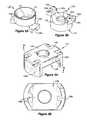
- FIGS. 1A-Care exploded perspective views of the locking mechanism of the present invention with a fixation device and a stabilization device;
- FIG. 2Ais a cross-sectional side view of the locking mechanism of the present invention with a fixation device and a stabilization device showing the washer not fully engaged with the seat;
- FIG. 2Bis a cross-sectional front view of the locking mechanism of the present invention with a fixation device and a stabilization device showing the washer not fully engaged with the seat;
- FIG. 2Cis a cross-sectional side view of the locking mechanism of the present invention with a fixation device and a stabilization device showing the washer fully engaged with the seat;
- FIG. 2Dis a cross-sectional front view of the locking mechanism of the present invention with a fixation device and a stabilization device showing the washer fully engaged with the seat;
- FIG. 2Eis a side view of the washer, cap and locking channel of the side portion of the seat with the cap not fully engaged;
- FIGS. 3A-Bare top perspective and bottom perspective views of a washer according to the present invention.
- FIGS. 4A-Bare top perspective and bottom perspective views of a cap according to the present invention.
- FIGS. 5A-Bare perspective views of exemplary fixation devices with which the present invention can be used.
- FIGS. 1A-C and 2 A-Dshow exploded perspective views of the locking mechanism of the present invention
- FIGS. 2 A-Dshow cross sectional views of the locking mechanism of the present invention.
- the locking mechanism 100is configured to engage and lock the relative position of a fixation device 104 with respect to the seat 102 .
- the locking mechanismmay also be configured to lock the relative position of the stabilization device 106 with respect to the seat 102 .
- the fixation device 104can be locked independent of the stabilization device 106 .
- the locking mechanism 100includes a seat 102 , a washer 108 and a cap 110 .
- the seat 102includes a bottom portion 114 that is configured to receive the fixation device 104 such that a socket 116 of the bottom portion 114 engages part of the fixation device 104 and prevents the fixation device 104 from passing entirely therethrough.
- the fixation device 104may be, for example, a screw having a head 140 and a shaft 142 with threads 144 . Examples of fixation devices 104 are shown in FIGS. 5A and 5B .
- the seat 102preferably includes a hole 118 that is larger than the shaft 142 and smaller than the head 140 .
- the socket 116 of the bottom portion 114 of the seat 102engages the head 140 of the fixation device 104 .
- the socket 116 of the bottom portion 114may be tapered to receive and engage the fixation device 104 .
- the seat 102also includes a side portion 112 that is configured to receive the stabilization device 106 , the washer 108 and the cap 110 .
- the stabilization device 106may be, for example, a rod, and the side portion 112 of the seat 102 may include a channel 124 for receiving the stabilization device 106 .
- the washer 108 and side portion 112are configured for engagement between the fixation device 104 and stabilization device 106 .
- the washer 108 and side portion 112may be, for example, slidably engageable, rotatably engageable and/or snapably engageable. In the presently preferred embodiment, the washer 108 and side portion 112 are rotatably engageable.
- the side portion 112 of the seat 102may include at least one groove 120 configured to accept the washer 108 .
- the washer 108is at least partially engageable with the side portion 112 such that the fixation device 104 is caused to become at least partially locked so as to facilitate placement and alignment of the stabilization device 106 .
- the washer 108is preferably disengageable from the side portion 112 so as to facilitate a change in placement or alignment of the fixation device 104 .
- the washer 108may also be configured such that the washer 108 permits access to the fixation device 104 when the washer 108 is at least partially engaged with the side portion 112 .
- the washer 108 and the cap 110are also configured for engagement, as are the cap 110 and the side portion 112 .
- the side portion 112may be configured to receive both the washer 108 and the cap 110 such that the washer 108 and the cap 110 cooperate in mating engagement.
- the side portion 112may be further configured such that the mated washer 108 and cap 110 are lockingly engageable with the side portion 112 to cause locking of the fixation device 104 independent of the stabilization device 106 .
- the locking mechanism 100may also include a locking element 201 for locking the position of the stabilization device 106 .
- the locking elementinclude a screw, a breakaway screw, a washer, a 90 degree washer, a linear wedge, a washer and nut and a snap-in lock.
- the stabilization device 106may also be locked independent of the fixation device 104 .
- FIGS. 2A-Dthe locking mechanism 100 of the present invention is illustrated in greater detail.
- FIGS. 2A and 2Care cross-sectional side views of the locking mechanism 100 of the present invention with a stabilization device 106 , as well as a fixation device 104 in unlocked and locked positions, respectively.
- FIGS. 2B and 2Dare cross-sectional front views of the locking mechanism 100 of the present invention with a stabilization device 106 , as well as a fixation device 104 in unlocked and locked positions, respectively.
- the locking mechanism 100includes a seat 102 , a washer 108 and a cap 110 for locking a fixation device 104 .
- the locking mechanism 100may also include a locking element for engaging a stabilization device 106 .
- Each of the seat 102 , fixation device 104 , stabilization device 106 , washer 108 , cap 110 and locking elementmay be made from a variety of materials known in the art and preferably are made from biocompatible materials when the locking mechanism 100 is used for bone fixation. Such materials include, but are not limited to, titanium, titanium alloys (e.g.
- titanium/aluminum/vanadium (Ti/Al/V) alloystitanium/aluminum/vanadium (Ti/Al/V) alloys), cobalt-chromium alloys, stainless steel, ceramics (alumina ceramic, zirconia ceramic, yttria zirconia ceramic, etc.), high strength polymers (e.g. PEEK, PEKK, etc.), pyrolytic carbon, tantalum, carbon composite materials and combinations thereof.
- Some materialsare more appropriate for fixation surfaces, such as cobalt-chromium alloys, titanium, and (Ti/Al/V) alloys, but any material known in the art for use with fixation surfaces can be used in the present invention. Such materials are commonly used in bone fixation and the like.
- the materialsare rigid and in one embodiment, the seat 102 , fixation device 104 , stabilization device 106 , washer 108 and cap 110 are all made from Ti/Al/V alloys, such as Ti/6Al/4V ELI.
- fixation devices 104other than a screw can be used without departing from the scope of the present invention
- a screwis shown and described herein to illustrate the engagement of the fixation device 104 and the seat 102 , as well as the method for locking the relative positions of a fixation device 104 and a stabilization device 106 .
- various types of screwsmay be used. Two exemplary types of screws are illustrated in FIGS. 5A and 5B .
- the size of the seat 102may be similar to that of prior art devices.
- the height of seat 102may range from about 0.25 inch to about 1 inch. In one embodiment, the height of the seat 102 ranges from about 0.4 inch to about 0.45 inch.
- the width of seat 102may range from about 0.25 inch to about 1 inch. In one embodiment, the width of the seat 102 ranges from about 0.39 inch to about 0.42 inch.
- the seat 102has a side portion 112 and a bottom portion 114 .
- the bottom portion 114may be tapered as shown in FIGS. 2B and 2D and includes a socket 116 and a hole 118 .
- “above”means posterior with respect to the patient and “below” means anterior with respect to the patient.
- the bottom portion 114 of the seat 102is anterior with respect to the patient and the fixation device 104 and stabilization device 106 are received by the seat 102 as the fixation device 104 and stabilization device 106 are moved in a posterior to anterior direction.
- this type of seat 102is often referred to as a “tulip” by those skilled in the art.
- the socket 116is preferably sized to accept a fixation device 104 , such as a screw, and the hole 118 is preferably sized to prevent the fixation device 104 from passing entirely therethrough.
- the hole 118is preferably located at the bottom of the seat 102 .
- the socket 116is configured for engagement of the fixation device 104 , or more specifically, the engagement surface 146 of the head 140 of the fixation device 104 .
- the surface of the socket 116may include a rough or knurled surface and/or a surface fixation mechanism, such as ridges, grooves, bumps, pips, or the like.
- an engagement surface 146 of the head 140 of the fixation device 104may have a similar surface.
- the side portion 112includes grooves 120 for engaging the washer 108 .
- the washer 108may be placed into the seat 102 from an opening in the top of the seat 102 .
- the washer 108has wings 126 that extend laterally from the body of the washer 108 .
- the grooves 120may be parallel-sided within the seat 102 , but may also be angled to help prevent splay when engaging the wings 126 of the washer 108 .
- the washer 108is preferably oriented so that the wings 126 reside within the channel 124 of the seat 102 . Once within the seat 102 , the washer 108 can be rotated to engage the grooves 120 of the side portion 112 of the seat 102 to prevent the washer 108 from retracting from the seat 102 .
- the wings 126 of the washer 108are engageable with the grooves 120 .
- the grooves 120are configured for more than one level of engagement with the wings 126 .
- each of the grooves 120narrows to create a tighter engagement as the washer 108 is rotated.
- the grooves 120may include an angle of activation 122 that narrows the channel and causes tighter engagement of the grooves 120 and the wings 126 .
- the angle of activationnarrows the top part of the groove 120 , which forces the washer 108 down onto the fixation device 104 to cause at least a partial locking of the position of the fixation device 104 .
- the washer 108may be configured such that a stabilization device 106 can be placed between the wings 126 without first engaging the wings 126 and the grooves 120 . In this configuration, the washer 108 is preferably capable of being rotated a sufficient amount without the wings 126 butting against the stabilization device 106 .
- the outer edge of the wings 126may be eccentrically round such that the eccentricity causes wedging as the wings 126 are rotated.
- the groove 120can be eccentric such that eccentricity of the groove 120 causes wedging.
- the washer 108may be engageable with the seat 102 such that the washer 108 does not pass through the side portion 112 of the seat 102 .
- the washer 108may be configured for locking engagement with grooves, such as grooves 120 , of the side portion 112 of the seat 102 .
- the washer 108 and seat 102may also be configured for engagement using any other suitable locking mechanism known in the art.
- the washer 108may be engageable with the seat 102 such that the interaction of the washer 108 and the seat 102 alone is sufficient to lock the position of the fixation device 104 .
- a toolcan be used to cause the washer 108 to engageable with the side portion 112 .
- the toolmay be attach to the washer 108 and be used to place the washer 108 at the appropriate position for engagement, and then be used to rotate the washer 108 to cause engagement with the side portion 112 .
- the seat 102also has a channel 124 in the side portion 112 for receiving the stabilization device 106 , such as a rod. While a channel 124 is preferred for receiving the stabilization device 106 , it will be understood by those skilled in the art that an aperture in the side portion 112 could also receive the stabilization device 106 , though a seat 102 with an aperture may be more cumbersome to use during surgery as a surgeon would have to thread the stabilization device 106 through the aperture instead of placing the stabilization device in the channel 124 . Using a channel 124 to receive the stabilization device 106 provides greater flexibility for a surgeon.
- a cap 110retains the stabilization device within the seat 102 and interacts with the washer 108 and seat 102 to fix the fixation device 104 .
- FIG. 2Eillustrates the engagement of the side portion 112 of the seat 102 , the washer 108 and the cap 110 .
- the side portion 112includes locking channels 152 configured for engagement with both the washer 108 and the cap 110 .
- the locking channels 152may be, for example, non-threaded, non-wedging channels.
- the locking channels 152extend to the grooves 120 and are J-shaped channels.
- the washer 108is rotated such that the female receivers 128 are aligned with alignment portions 154 of the locking channels 152 .
- the cap 110is placed over the seat 102 such that male members 158 of the cap 110 engage the locking channels 152 and the female receivers 128 .
- the cap 110 and washer 108 combinationis then rotated such that the male member 158 and female receiver 128 combination enters the locking portion 156 of the locking channel 152 .
- the locking portion 156is preferably a pull-up lock that prevents the combination from backing out. Accordingly, when the cap 110 is pulled up, the male member 158 is restrained from unlocking by the tip of the “J” shape of the locking channel 152 .
- the male members 158may be configured such that the male members 158 partially tear off when the cap 110 is disengaged after being fully engaged in the locking channel 152 . This may occur, for example, during revision surgery. The cap 110 may then be discarded and a new cap 110 having slightly different shaped male members 158 may be used to create a new locking engagement.
- the rotation of the cap 110 to a locked positioncauses the washer 108 to further engage the grooves 120 , thereby locking the fixation device 104 with respect to the seat 102 .
- the stabilization device 106is not locked by the rotation of the cap 110 and washer 108 . Rather, the stabilization device 106 can be repositioned as necessary during a procedure involving the use of the locking mechanism 100 . Accordingly, the fixation device 104 is locked independent of the stabilization device 106 .
- fixation device 104may be locked and unlocked multiple times prior to locking the stabilization device 106 .
- the washer 108is configured for placement between a fixation device 104 and a stabilization device 106 and functions to lock the fixation device 104 in a fixed position.
- the washer 108may be made from a titanium alloy and has a fixation device side 132 and a stabilization device side 130 .
- the surfaces of the fixation device side 132 and/or the stabilization device side 130may be relatively smooth, or may have a rough or knurled surface and/or a surface fixation mechanism, such as ridges, grooves, bumps, pips, or the like to increase the surface coefficient of friction.
- the stabilization device side 130 or fixation device side 132may be roughened by aluminum oxide blasting.
- any of the surfaces of the locking mechanism 100 , any of the surfaces of the fixation device 104 and/or any of the surfaces of the stabilization device 106may also be surface treated.
- the fixation device side 132may also be contoured to improve engagement with the fixation device 104 .
- the contourmay increase the area over which the washer 108 and fixation device 104 are engaged.
- the head fixation side 132may be contoured such that it includes a channel with a curvature that approximates the curvature of the head 140 .
- the stabilization device side 130may be contoured to increase the area over which the washer 108 and stabilization device 106 are engaged.
- the stabilization device side 130may be contoured such that it includes a channel with a curvature that approximates the curvature of the outer surface of the rod. It will understood by those in the art that the contour may alternatively decrease in the area over which the washer 108 and fixation device 104 are engaged.
- the fixation device side 132may be designed so that it enhances the fixation of the fixation device 104 to a target.
- the fixation device side 132may include interdigitating fingers, ridges or other mechanism for increasing the interaction between the fixation device side 132 and the fixation device 104 , such as a screw.
- the washer 108is rotatably engageable with grooves 120 a and 120 b of the side portion 112 of the seat 102 .
- the washer 108includes wings 126 a and 126 b for engagement with grooves 120 a and 120 b .
- Each of the wings 126 a and 126 bpreferably includes a chamfer 150 a and 150 b , respectively, for facilitating engagement with the grooves 120 a and 120 b .
- Each of the wings 126 a and 126 balso preferably includes a female receiver 128 a and 128 b , respectively, configured for mating engagement with male member of the cap 110 .
- the female receivers 128 a and 128 bare preferably aligned with alignment portions 154 a and 154 b of the locking channels 152 a and 152 b of the side portion 112 of the seat 102 .
- the washer 108may include an access hole 134 for providing access to the fixation device 104 after the washer 108 is at least partially engaged with the side portion 112 of the seat 102 .
- a drive mechanismcan pass through the access hole 134 to exert drive force on the fixation device 104 .
- the specific shapes and types of the grooves 120 a and 120 b and wings 126 a and 126 bmay vary substantially.
- the grooves 120may include miniature slots on their interiors to interact with small bumps on the wings 126 so that it is apparent when the wing 126 and groove 120 are properly engaged.
- the wings 126may each have a surface with small ridges to create increased friction between the wings 126 and the grooves 120 to help prevent the washer 108 from disengaging.
- Such surfacesmay be rough or knurled and/or include at least one surface fixation mechanism, such as ridges, grooves, bumps, pips, or the like to increase the surface coefficient of friction.
- the surfacesmay be roughened by aluminum oxide blasting.
- other surface treatmentsmay also be used.
- an intermediate elementmay be used between the washer 108 and either or both the fixation device 104 and stabilization device 106 without departing from the scope of the present invention.
- the intermediate elementmay be a spacer between the washer 108 and the fixation device 104 .
- the spacermay thus be configured to have contoured surface, and/or interdigitating fingers, like those described with reference to the fixation device surface 132 of the washer 108 .
- in intermediate element between the washer 108 and stabilization device 106may have a surface similar to the stabilization device surface 130 .
- FIGS. 4A and 4Billustrate an exemplary cap 110 for use with the seat 102 of FIGS. 1A-C and 2 A-F.
- the cap 110retains the stabilization device 106 in the channel 124 and engages the washer 108 to cause fixation of the fixation device 104 .
- the cap 110may be, for example, hingedly connected to the seat 102 , either vertically or horizontally.
- the cap 110is longer in one direction than in the other.
- the cap 110is preferably placed on the seat 102 such that it is generally perpendicular to the major axis of the stabilization device 106 .
- the cap 110preferably has a top surface 136 and a stabilization device surface 138 .
- the stabilization device surface 138may include a contour that approximates the outer surface of the stabilization device 106 .
- the cap 110may also have an access hole 148 for facilitating locking engagement of the stabilization device 106 within the seat 102 . The locking of the stabilization device 106 may be accomplished by a locking element (not shown) passing through the access hole 148 .
- the cap 110also preferably has male members 158 a and 158 b for engaging locking channels 152 a and 152 b and female receivers 128 a and 128 b .
- the male members 158 a and 158 bWhen placed on the seat 102 , the male members 158 a and 158 b preferably engage the locking channels 152 a and 152 b and the female receivers 128 a and 128 b .
- the male members 152 and female receivers 128may be disengageably engageable in the alignment portion 154 of the locking channel 152 .
- the cap 110can then be rotated, thereby causing the washer 108 to rotate.
- the male members 158 a and 158 bare positioned in the locking portions 156 a and 156 b of the locking channels 152 a and 152 b where the male members 152 and female receivers 128 may be lockingly engageable. Locking is accomplished as described above with reference to FIG. 2E .
- engagement of the cap 110 and washer 108may also be accomplished without using male members 158 and female receivers 128 .
- the surfaces of the cap 110 and washer 108may be configured to have grooves, ridges, a fork around the wings of the washer 108 , or the like to cause engagement of the cap 110 and washer 108 .
- the locking mechanismmay also include a locking element (not shown) for fixing the position of the stabilization device 106 .
- the locking elementmay be configured to interact with the cap 110 to cause engagement of the stabilization device.
- the locking elementmay be a screw, such as a breakaway screw, that passes through the access hole 148 , which may be threaded.
- the locking elementmay act to force the cap 110 away from the stabilization device 106 and force the male members 158 into the tip of the locking portion 154 of the locking channels 152 , thereby locking the cap 110 .
- the locking elementmay force the stabilization device 106 down into the washer 108 , thereby locking the stabilization device 106 into position.
- Other mechanisms for locking the stabilization device 106may also be used, so long as the stabilization device 106 is locked independent of the fixation device 104 .
- locking elementsinclude, for example: a screw, a breakaway screw, a 90 degree wedge, a linear wedge, a washer and nut, a snap-in lock, or the like.
- the fixation mechanism 100 of the present inventionprovides a convenient method for engaging and locking a relative position of a fixation device 104 and a stabilization device 106 .
- the fixation device 104is passed through the bottom portion 114 of the seat 102 and then fixed to a target, such as a spinal vertebra or other bone.
- a washer 108is then engaged with a side portion 112 of the seat 102 such that a receiver 128 on the washer 108 and locking channel 152 on the side portion 112 of the seat are aligned.
- a stabilization device 106is placed in a side portion 112 of the seat 102 .
- the stabilization device 106is placed in a channel 124 .
- a cap 110 having a male member 158is placed atop the seat 102 such that the male member 158 engages the locking channel 152 and the receiver 128 .
- the fixation device 104is then locked with respect to the seat 102 . Locking of the fixation device 104 may be accomplished by rotating the combination receiver 128 and male member 158 from an alignment portion 154 of the locking channel 152 into a locking portion 156 of the locking channel 152 .
- the stabilization device 106may be locked with respect to the seat 102 after the fixation device 104 is at least temporarily locked.
- a locking elementmay be engaged.
- part of the seat 102may be peened such that the fixation device 104 , washer 108 and seat 102 essentially function as a single piece. This minimizes the number of steps required during installation of the locking mechanism 100 .
Landscapes
- Health & Medical Sciences (AREA)
- Orthopedic Medicine & Surgery (AREA)
- Life Sciences & Earth Sciences (AREA)
- Neurology (AREA)
- Surgery (AREA)
- Heart & Thoracic Surgery (AREA)
- Engineering & Computer Science (AREA)
- Biomedical Technology (AREA)
- Nuclear Medicine, Radiotherapy & Molecular Imaging (AREA)
- Medical Informatics (AREA)
- Molecular Biology (AREA)
- Animal Behavior & Ethology (AREA)
- General Health & Medical Sciences (AREA)
- Public Health (AREA)
- Veterinary Medicine (AREA)
- Surgical Instruments (AREA)
- Closures For Containers (AREA)
Abstract
Description
Claims (30)
Priority Applications (6)
| Application Number | Priority Date | Filing Date | Title |
|---|---|---|---|
| US11/121,414US7811310B2 (en) | 2005-05-04 | 2005-05-04 | Multistage spinal fixation locking mechanism |
| PCT/US2006/016788WO2006119271A2 (en) | 2005-05-04 | 2006-05-04 | Multistage spinal fixation locking mechanism |
| JP2008510126AJP4995813B2 (en) | 2005-05-04 | 2006-05-04 | Spinal fixation locking mechanism |
| EP06769955.3AEP1876983B1 (en) | 2005-05-04 | 2006-05-04 | Multistage spinal fixation locking mechanism |
| CN200680014027.XACN101166477B (en) | 2005-05-04 | 2006-05-04 | Multistage spinal fixation locking mechanism |
| US12/558,046US8048124B2 (en) | 2005-05-04 | 2009-09-11 | Spinal screw assembly and screw insertion tool |
Applications Claiming Priority (1)
| Application Number | Priority Date | Filing Date | Title |
|---|---|---|---|
| US11/121,414US7811310B2 (en) | 2005-05-04 | 2005-05-04 | Multistage spinal fixation locking mechanism |
Related Child Applications (1)
| Application Number | Title | Priority Date | Filing Date |
|---|---|---|---|
| US12/558,046Continuation-In-PartUS8048124B2 (en) | 2005-05-04 | 2009-09-11 | Spinal screw assembly and screw insertion tool |
Publications (2)
| Publication Number | Publication Date |
|---|---|
| US20060264933A1 US20060264933A1 (en) | 2006-11-23 |
| US7811310B2true US7811310B2 (en) | 2010-10-12 |
Family
ID=37075067
Family Applications (1)
| Application Number | Title | Priority Date | Filing Date |
|---|---|---|---|
| US11/121,414Expired - Fee RelatedUS7811310B2 (en) | 2005-05-04 | 2005-05-04 | Multistage spinal fixation locking mechanism |
Country Status (5)
| Country | Link |
|---|---|
| US (1) | US7811310B2 (en) |
| EP (1) | EP1876983B1 (en) |
| JP (1) | JP4995813B2 (en) |
| CN (1) | CN101166477B (en) |
| WO (1) | WO2006119271A2 (en) |
Cited By (68)
| Publication number | Priority date | Publication date | Assignee | Title |
|---|---|---|---|---|
| US20090082819A1 (en)* | 2007-06-28 | 2009-03-26 | Spinal Elements, Inc. | Spinal stabilization device |
| US20100106189A1 (en)* | 2008-10-29 | 2010-04-29 | Warsaw Orthopedic, Inc. | Anchor with two member securing mechanism for attaching an elongated member to a bone |
| US20100114168A1 (en)* | 2008-10-30 | 2010-05-06 | Warsaw Orthopedic, Inc. | Anchor with non-threaded securing mechanism to attach an elongated member to a bone |
| US20110060374A1 (en)* | 2003-12-16 | 2011-03-10 | Christopher Sicvol | Percutaneous Access Devices And Bone Anchor Assemblies |
| US20110112578A1 (en)* | 2009-11-09 | 2011-05-12 | Ebi, Llc | Multiplanar bone anchor system |
| US8246657B1 (en) | 2009-06-29 | 2012-08-21 | Nuvasive, Inc. | Spinal cross connector |
| US8377067B2 (en) | 2004-02-27 | 2013-02-19 | Roger P. Jackson | Orthopedic implant rod reduction tool set and method |
| US8394133B2 (en) | 2004-02-27 | 2013-03-12 | Roger P. Jackson | Dynamic fixation assemblies with inner core and outer coil-like member |
| US8444681B2 (en) | 2009-06-15 | 2013-05-21 | Roger P. Jackson | Polyaxial bone anchor with pop-on shank, friction fit retainer and winged insert |
| US8790374B2 (en) | 2004-04-08 | 2014-07-29 | Globus Medical, Inc. | Polyaxial screw |
| US8814911B2 (en) | 2003-06-18 | 2014-08-26 | Roger P. Jackson | Polyaxial bone screw with cam connection and lock and release insert |
| US20140249590A1 (en)* | 2005-04-25 | 2014-09-04 | Depuy Synthes Products Llc | Bone anchor with locking cap and method of spinal fixation |
| US8888827B2 (en) | 2011-07-15 | 2014-11-18 | Globus Medical, Inc. | Orthopedic fixation devices and methods of installation thereof |
| US8894657B2 (en) | 2004-02-27 | 2014-11-25 | Roger P. Jackson | Tool system for dynamic spinal implants |
| US8911479B2 (en) | 2012-01-10 | 2014-12-16 | Roger P. Jackson | Multi-start closures for open implants |
| US20150088202A1 (en)* | 2013-09-25 | 2015-03-26 | Blackstone Medical, Inc. | Bone screw systems with pressure caps having biasing members |
| US8998959B2 (en) | 2009-06-15 | 2015-04-07 | Roger P Jackson | Polyaxial bone anchors with pop-on shank, fully constrained friction fit retainer and lock and release insert |
| US9044272B2 (en) | 2009-11-09 | 2015-06-02 | Ebi, Llc | Multiplanar bone anchor system |
| US9050139B2 (en) | 2004-02-27 | 2015-06-09 | Roger P. Jackson | Orthopedic implant rod reduction tool set and method |
| US9168069B2 (en) | 2009-06-15 | 2015-10-27 | Roger P. Jackson | Polyaxial bone anchor with pop-on shank and winged insert with lower skirt for engaging a friction fit retainer |
| US9186187B2 (en) | 2011-07-15 | 2015-11-17 | Globus Medical, Inc. | Orthopedic fixation devices and methods of installation thereof |
| US9198694B2 (en) | 2011-07-15 | 2015-12-01 | Globus Medical, Inc. | Orthopedic fixation devices and methods of installation thereof |
| US9216039B2 (en) | 2004-02-27 | 2015-12-22 | Roger P. Jackson | Dynamic spinal stabilization assemblies, tool set and method |
| US9259254B2 (en) | 2004-04-08 | 2016-02-16 | Globus Medical, Inc. | Polyaxial screw |
| US9271759B2 (en) | 2012-03-09 | 2016-03-01 | Institute Of Musculoskeletal Science And Education, Ltd. | Pedicle screw assembly with locking cap |
| US9358047B2 (en) | 2011-07-15 | 2016-06-07 | Globus Medical, Inc. | Orthopedic fixation devices and methods of installation thereof |
| US9393047B2 (en) | 2009-06-15 | 2016-07-19 | Roger P. Jackson | Polyaxial bone anchor with pop-on shank and friction fit retainer with low profile edge lock |
| USRE46115E1 (en) | 2005-09-19 | 2016-08-23 | Ebi, Llc | Bone screw apparatus, system and method |
| US9480517B2 (en) | 2009-06-15 | 2016-11-01 | Roger P. Jackson | Polyaxial bone anchor with pop-on shank, shank, friction fit retainer, winged insert and low profile edge lock |
| US9480501B2 (en) | 2013-10-21 | 2016-11-01 | Blackstone Medical, Inc. | Modular pedicle screw |
| US9532815B2 (en) | 2004-02-27 | 2017-01-03 | Roger P. Jackson | Spinal fixation tool set and method |
| US20170112543A1 (en)* | 2005-05-27 | 2017-04-27 | Roger P. Jackson | Polyaxial bone screw with shank articulation pressure insert and method |
| US9707100B2 (en) | 2015-06-25 | 2017-07-18 | Institute for Musculoskeletal Science and Education, Ltd. | Interbody fusion device and system for implantation |
| US9907574B2 (en) | 2008-08-01 | 2018-03-06 | Roger P. Jackson | Polyaxial bone anchors with pop-on shank, friction fit fully restrained retainer, insert and tool receiving features |
| US20180098796A1 (en)* | 2008-09-05 | 2018-04-12 | DePuy Synthes Products, Inc. | Bone Fixation Assembly |
| US9956009B1 (en) | 2011-03-01 | 2018-05-01 | Nuvasive, Inc. | Posterior cervical fixation system |
| US9980758B2 (en) | 2013-11-27 | 2018-05-29 | Blackstone Medical, Inc. | Minimally invasive counter-torque wrench system |
| US9980753B2 (en) | 2009-06-15 | 2018-05-29 | Roger P Jackson | pivotal anchor with snap-in-place insert having rotation blocking extensions |
| US9987047B2 (en) | 2013-10-07 | 2018-06-05 | Spine Wave, Inc. | Translating polyaxial screw |
| US9993269B2 (en) | 2011-07-15 | 2018-06-12 | Globus Medical, Inc. | Orthopedic fixation devices and methods of installation thereof |
| US9999452B2 (en) | 2004-11-23 | 2018-06-19 | Roger P. Jackson | Bone anchor receiver with upper tool engaging grooves and planar faces |
| US10039578B2 (en) | 2003-12-16 | 2018-08-07 | DePuy Synthes Products, Inc. | Methods and devices for minimally invasive spinal fixation element placement |
| US10194951B2 (en) | 2005-05-10 | 2019-02-05 | Roger P. Jackson | Polyaxial bone anchor with compound articulation and pop-on shank |
| US10363070B2 (en) | 2009-06-15 | 2019-07-30 | Roger P. Jackson | Pivotal bone anchor assemblies with pressure inserts and snap on articulating retainers |
| US10485588B2 (en) | 2004-02-27 | 2019-11-26 | Nuvasive, Inc. | Spinal fixation tool attachment structure |
| US11234745B2 (en) | 2005-07-14 | 2022-02-01 | Roger P. Jackson | Polyaxial bone screw assembly with partially spherical screw head and twist in place pressure insert |
| US11241261B2 (en) | 2005-09-30 | 2022-02-08 | Roger P Jackson | Apparatus and method for soft spinal stabilization using a tensionable cord and releasable end structure |
| US11360523B2 (en) | 2018-03-06 | 2022-06-14 | Hewlett-Packard Development Company, L.P. | Hinge assemblies with composite neck shafts |
| US11419642B2 (en) | 2003-12-16 | 2022-08-23 | Medos International Sarl | Percutaneous access devices and bone anchor assemblies |
| US11464545B1 (en) | 2021-07-02 | 2022-10-11 | Indius Medical Technologies Private Limited | Anti-splay bone anchor |
| US11559335B2 (en) | 2009-06-15 | 2023-01-24 | Roger P Jackson | Pivotal bone anchor assembly with insert tool deployment |
| US11730526B2 (en) | 2019-12-17 | 2023-08-22 | Roger P. Jackson | Bone anchor assembly with ring retainer and internal snap ring |
| US11751915B2 (en) | 2021-07-09 | 2023-09-12 | Roger P. Jackson | Modular spinal fixation system with bottom-loaded universal shank heads |
| US11793553B2 (en) | 2014-10-21 | 2023-10-24 | Roger P. Jackson | Pivotal bone anchor assembly having first and second split rings and an insert with post-placement tool deployment |
| US11819249B2 (en) | 2009-06-15 | 2023-11-21 | Roger P. Jackson | Pivotal bone anchor assembly having twist-in-place insert with forced interference downward displacement |
| US11872143B2 (en) | 2016-10-25 | 2024-01-16 | Camber Spine Technologies, LLC | Spinal fusion implant |
| US11877935B2 (en) | 2016-10-18 | 2024-01-23 | Camber Spine Technologies, LLC | Implant with deployable blades |
| US11925392B2 (en) | 2007-05-23 | 2024-03-12 | Roger P. Jackson | Pivotal bone anchor assembly with bottom loaded spherical shank head having a planar upper surface |
| US12042185B2 (en) | 2010-05-14 | 2024-07-23 | Roger P. Jackson | Pivotal bone anchor assembly with resiliently biased friction fit insert |
| US12070249B2 (en) | 2014-06-04 | 2024-08-27 | Jackson Roger P | Pivotal bone anchor assembly with bottom loaded shank head engaging retainer and closure engaging insert |
| US12082853B2 (en) | 2014-10-21 | 2024-09-10 | Roger P. Jackson | Pivotal bone anchor assembly with positioner-retainer containment and insert tool deployment |
| US12082850B2 (en) | 2007-09-17 | 2024-09-10 | Roger P. Jackson | Pivotal bone anchor assembly having twist-in-place insert and receiver with pre-formed axial rotation insert stops |
| US12102357B2 (en) | 2005-02-22 | 2024-10-01 | Roger P. Jackson | Pivotal bone anchor assembly with cannulated shank having a planar top surface and method of assembly |
| US12137945B2 (en) | 2018-09-13 | 2024-11-12 | Roger P. Jackson | Pivotal bone anchor system with modular receiver sub-assemblies and universal bone anchors |
| US12262920B2 (en) | 2004-11-23 | 2025-04-01 | Roger P. Jackson | Method of assembling a bottom-loaded pivotal bone anchor assembly with compression insert and two-part shank retainer |
| US12357348B2 (en) | 2005-09-30 | 2025-07-15 | Roger P. Jackson | Method of assembling a pivotal bone anchor assembly with press-in-place insert |
| US12414801B2 (en) | 2022-11-03 | 2025-09-16 | Roger P. Jackson | Spinal fixation system with modular receiver sub-assemblies for connecting with bi-spherical universal shank heads |
| US12440245B2 (en) | 2023-09-06 | 2025-10-14 | Pivotable bone anchor assembly with independent provisional locking by insert compressing member |
Families Citing this family (107)
| Publication number | Priority date | Publication date | Assignee | Title |
|---|---|---|---|---|
| US7833250B2 (en) | 2004-11-10 | 2010-11-16 | Jackson Roger P | Polyaxial bone screw with helically wound capture connection |
| US10729469B2 (en) | 2006-01-09 | 2020-08-04 | Roger P. Jackson | Flexible spinal stabilization assembly with spacer having off-axis core member |
| US8292926B2 (en) | 2005-09-30 | 2012-10-23 | Jackson Roger P | Dynamic stabilization connecting member with elastic core and outer sleeve |
| US10258382B2 (en) | 2007-01-18 | 2019-04-16 | Roger P. Jackson | Rod-cord dynamic connection assemblies with slidable bone anchor attachment members along the cord |
| WO2006052796A2 (en) | 2004-11-10 | 2006-05-18 | Jackson Roger P | Helical guide and advancement flange with break-off extensions |
| US8876868B2 (en) | 2002-09-06 | 2014-11-04 | Roger P. Jackson | Helical guide and advancement flange with radially loaded lip |
| US7141051B2 (en) | 2003-02-05 | 2006-11-28 | Pioneer Laboratories, Inc. | Low profile spinal fixation system |
| US7377923B2 (en) | 2003-05-22 | 2008-05-27 | Alphatec Spine, Inc. | Variable angle spinal screw assembly |
| US8257398B2 (en) | 2003-06-18 | 2012-09-04 | Jackson Roger P | Polyaxial bone screw with cam capture |
| US7967850B2 (en) | 2003-06-18 | 2011-06-28 | Jackson Roger P | Polyaxial bone anchor with helical capture connection, insert and dual locking assembly |
| US8377102B2 (en) | 2003-06-18 | 2013-02-19 | Roger P. Jackson | Polyaxial bone anchor with spline capture connection and lower pressure insert |
| US8926670B2 (en) | 2003-06-18 | 2015-01-06 | Roger P. Jackson | Polyaxial bone screw assembly |
| US8398682B2 (en) | 2003-06-18 | 2013-03-19 | Roger P. Jackson | Polyaxial bone screw assembly |
| US8137386B2 (en) | 2003-08-28 | 2012-03-20 | Jackson Roger P | Polyaxial bone screw apparatus |
| US7588590B2 (en) | 2003-12-10 | 2009-09-15 | Facet Solutions, Inc | Spinal facet implant with spherical implant apposition surface and bone bed and methods of use |
| US8333789B2 (en) | 2007-01-10 | 2012-12-18 | Gmedelaware 2 Llc | Facet joint replacement |
| US8562649B2 (en) | 2004-02-17 | 2013-10-22 | Gmedelaware 2 Llc | System and method for multiple level facet joint arthroplasty and fusion |
| US7507242B2 (en) | 2004-06-02 | 2009-03-24 | Facet Solutions | Surgical measurement and resection framework |
| US7651502B2 (en) | 2004-09-24 | 2010-01-26 | Jackson Roger P | Spinal fixation tool set and method for rod reduction and fastener insertion |
| US7794477B2 (en)* | 2004-10-05 | 2010-09-14 | Warsaw Orthopedic, Inc. | Spinal implants and methods with extended multi-axial anchor assemblies |
| US7722654B2 (en)* | 2004-10-05 | 2010-05-25 | Warsaw Orthopedic, Inc. | Spinal implants with multi-axial anchor assembly and methods |
| US7572280B2 (en)* | 2004-10-05 | 2009-08-11 | Warsaw Orthopedic, Inc. | Multi-axial anchor assemblies for spinal implants and methods |
| WO2006047711A2 (en) | 2004-10-25 | 2006-05-04 | Alphaspine, Inc. | Pedicle screw systems and methods |
| US7604655B2 (en) | 2004-10-25 | 2009-10-20 | X-Spine Systems, Inc. | Bone fixation system and method for using the same |
| US7691129B2 (en) | 2004-10-27 | 2010-04-06 | Felix Brent A | Spinal stabilizing system |
| US8926672B2 (en) | 2004-11-10 | 2015-01-06 | Roger P. Jackson | Splay control closure for open bone anchor |
| US9216041B2 (en) | 2009-06-15 | 2015-12-22 | Roger P. Jackson | Spinal connecting members with tensioned cords and rigid sleeves for engaging compression inserts |
| US8308782B2 (en) | 2004-11-23 | 2012-11-13 | Jackson Roger P | Bone anchors with longitudinal connecting member engaging inserts and closures for fixation and optional angulation |
| WO2006058221A2 (en) | 2004-11-24 | 2006-06-01 | Abdou Samy M | Devices and methods for inter-vertebral orthopedic device placement |
| US7901437B2 (en) | 2007-01-26 | 2011-03-08 | Jackson Roger P | Dynamic stabilization member with molded connection |
| US10076361B2 (en) | 2005-02-22 | 2018-09-18 | Roger P. Jackson | Polyaxial bone screw with spherical capture, compression and alignment and retention structures |
| US8048124B2 (en)* | 2005-05-04 | 2011-11-01 | Spinefrontier Inc | Spinal screw assembly and screw insertion tool |
| US7766946B2 (en)* | 2005-07-27 | 2010-08-03 | Frank Emile Bailly | Device for securing spinal rods |
| US7717943B2 (en) | 2005-07-29 | 2010-05-18 | X-Spine Systems, Inc. | Capless multiaxial screw and spinal fixation assembly and method |
| US8105368B2 (en) | 2005-09-30 | 2012-01-31 | Jackson Roger P | Dynamic stabilization connecting member with slitted core and outer sleeve |
| WO2007041702A2 (en) | 2005-10-04 | 2007-04-12 | Alphaspine, Inc. | Pedicle screw system with provisional locking aspects |
| US8097025B2 (en) | 2005-10-25 | 2012-01-17 | X-Spine Systems, Inc. | Pedicle screw system configured to receive a straight or curved rod |
| US7704271B2 (en) | 2005-12-19 | 2010-04-27 | Abdou M Samy | Devices and methods for inter-vertebral orthopedic device placement |
| US7833252B2 (en) | 2006-01-27 | 2010-11-16 | Warsaw Orthopedic, Inc. | Pivoting joints for spinal implants including designed resistance to motion and methods of use |
| US7722652B2 (en) | 2006-01-27 | 2010-05-25 | Warsaw Orthopedic, Inc. | Pivoting joints for spinal implants including designed resistance to motion and methods of use |
| US8057519B2 (en) | 2006-01-27 | 2011-11-15 | Warsaw Orthopedic, Inc. | Multi-axial screw assembly |
| CA2647026A1 (en) | 2006-03-22 | 2008-08-28 | Pioneer Surgical Technology, Inc. | Low top bone fixation system and method for using the same |
| US8062340B2 (en) | 2006-08-16 | 2011-11-22 | Pioneer Surgical Technology, Inc. | Spinal rod anchor device and method |
| US8016862B2 (en)* | 2006-09-27 | 2011-09-13 | Innovasis, Inc. | Spinal stabilizing system |
| JP2010505541A (en)* | 2006-10-05 | 2010-02-25 | ジャヴィン・ピアス | Anchor assembly for spinal implant system |
| US8066744B2 (en)* | 2006-11-10 | 2011-11-29 | Warsaw Orthopedic, Inc. | Keyed crown orientation for multi-axial screws |
| US8366745B2 (en) | 2007-05-01 | 2013-02-05 | Jackson Roger P | Dynamic stabilization assembly having pre-compressed spacers with differential displacements |
| US8475498B2 (en) | 2007-01-18 | 2013-07-02 | Roger P. Jackson | Dynamic stabilization connecting member with cord connection |
| US10383660B2 (en) | 2007-05-01 | 2019-08-20 | Roger P. Jackson | Soft stabilization assemblies with pretensioned cords |
| JP2010536533A (en)* | 2007-08-24 | 2010-12-02 | スピナル エレメンツ,インク. | Loop rod spinal fixation device |
| WO2009029928A1 (en)* | 2007-08-31 | 2009-03-05 | University Of South Florida | Translational manipulation polyaxial screw head |
| US20090076550A1 (en)* | 2007-09-18 | 2009-03-19 | Ortho Development Corporation | Spinal fixation system connectors |
| US8398683B2 (en) | 2007-10-23 | 2013-03-19 | Pioneer Surgical Technology, Inc. | Rod coupling assembly and methods for bone fixation |
| US8007522B2 (en) | 2008-02-04 | 2011-08-30 | Depuy Spine, Inc. | Methods for correction of spinal deformities |
| US9060813B1 (en) | 2008-02-29 | 2015-06-23 | Nuvasive, Inc. | Surgical fixation system and related methods |
| US8506601B2 (en) | 2008-10-14 | 2013-08-13 | Pioneer Surgical Technology, Inc. | Low profile dual locking fixation system and offset anchor member |
| US8636778B2 (en) | 2009-02-11 | 2014-01-28 | Pioneer Surgical Technology, Inc. | Wide angulation coupling members for bone fixation system |
| US9668771B2 (en) | 2009-06-15 | 2017-06-06 | Roger P Jackson | Soft stabilization assemblies with off-set connector |
| KR20120051692A (en)* | 2009-07-16 | 2012-05-22 | 스파인세이브 아게 | Spinal implant set including a quick closure |
| EP2485654B1 (en) | 2009-10-05 | 2021-05-05 | Jackson P. Roger | Polyaxial bone anchor with non-pivotable retainer and pop-on shank, some with friction fit |
| US8764806B2 (en) | 2009-12-07 | 2014-07-01 | Samy Abdou | Devices and methods for minimally invasive spinal stabilization and instrumentation |
| ES2525046T3 (en)* | 2009-12-21 | 2014-12-16 | Biedermann Technologies Gmbh & Co. Kg | Bone anchoring device |
| US8690924B2 (en)* | 2010-02-04 | 2014-04-08 | Spinefrontier Inc | Spinal screw assembly |
| US9198696B1 (en) | 2010-05-27 | 2015-12-01 | Nuvasive, Inc. | Cross-connector and related methods |
| AU2011299558A1 (en) | 2010-09-08 | 2013-05-02 | Roger P. Jackson | Dynamic stabilization members with elastic and inelastic sections |
| EP3047812B1 (en)* | 2010-11-22 | 2020-01-01 | Biedermann Technologies GmbH & Co. KG | Polyaxial bone anchoring device |
| EP2659845A1 (en) | 2010-12-27 | 2013-11-06 | Biedermann Technologies GmbH & Co. KG | Polyaxial bone anchoring device |
| US9247964B1 (en) | 2011-03-01 | 2016-02-02 | Nuasive, Inc. | Spinal Cross-connector |
| US8845728B1 (en) | 2011-09-23 | 2014-09-30 | Samy Abdou | Spinal fixation devices and methods of use |
| EP2591738A1 (en)* | 2011-11-14 | 2013-05-15 | Biedermann Technologies GmbH & Co. KG | Polyaxial bone anchoring device |
| US20130226240A1 (en) | 2012-02-22 | 2013-08-29 | Samy Abdou | Spinous process fixation devices and methods of use |
| EP2689734B1 (en)* | 2012-07-27 | 2016-09-14 | Biedermann Technologies GmbH & Co. KG | Polyaxial bone anchoring device with enlarged pivot angle |
| US9198767B2 (en) | 2012-08-28 | 2015-12-01 | Samy Abdou | Devices and methods for spinal stabilization and instrumentation |
| US9782204B2 (en) | 2012-09-28 | 2017-10-10 | Medos International Sarl | Bone anchor assemblies |
| US9320617B2 (en) | 2012-10-22 | 2016-04-26 | Cogent Spine, LLC | Devices and methods for spinal stabilization and instrumentation |
| US8911478B2 (en) | 2012-11-21 | 2014-12-16 | Roger P. Jackson | Splay control closure for open bone anchor |
| CN103070724B (en)* | 2013-01-28 | 2015-08-05 | 山东航维骨科医疗器械股份有限公司 | Pyramid fixator |
| US10058354B2 (en) | 2013-01-28 | 2018-08-28 | Roger P. Jackson | Pivotal bone anchor assembly with frictional shank head seating surfaces |
| US8852239B2 (en) | 2013-02-15 | 2014-10-07 | Roger P Jackson | Sagittal angle screw with integral shank and receiver |
| US9259247B2 (en) | 2013-03-14 | 2016-02-16 | Medos International Sarl | Locking compression members for use with bone anchor assemblies and methods |
| US20140277153A1 (en) | 2013-03-14 | 2014-09-18 | DePuy Synthes Products, LLC | Bone Anchor Assemblies and Methods With Improved Locking |
| US9775660B2 (en) | 2013-03-14 | 2017-10-03 | DePuy Synthes Products, Inc. | Bottom-loading bone anchor assemblies and methods |
| US9724145B2 (en) | 2013-03-14 | 2017-08-08 | Medos International Sarl | Bone anchor assemblies with multiple component bottom loading bone anchors |
| US10342582B2 (en) | 2013-03-14 | 2019-07-09 | DePuy Synthes Products, Inc. | Bone anchor assemblies and methods with improved locking |
| US9566092B2 (en) | 2013-10-29 | 2017-02-14 | Roger P. Jackson | Cervical bone anchor with collet retainer and outer locking sleeve |
| US9717533B2 (en) | 2013-12-12 | 2017-08-01 | Roger P. Jackson | Bone anchor closure pivot-splay control flange form guide and advancement structure |
| KR101499893B1 (en)* | 2013-12-26 | 2015-03-06 | 오스템임플란트 주식회사 | Attachment apparatus of dental structure |
| US9451993B2 (en) | 2014-01-09 | 2016-09-27 | Roger P. Jackson | Bi-radial pop-on cervical bone anchor |
| FR3019030B1 (en)* | 2014-03-26 | 2018-01-05 | Iceram | LACET BLOCKER OR LINK FOR SPINAL ARTHRODESIS |
| US9597119B2 (en) | 2014-06-04 | 2017-03-21 | Roger P. Jackson | Polyaxial bone anchor with polymer sleeve |
| US10149702B2 (en) | 2015-01-12 | 2018-12-11 | Imds Llc | Polyaxial screw and rod system |
| US9968378B1 (en) | 2015-07-22 | 2018-05-15 | University Of South Florida | Adaptation sphere saddle |
| US10857003B1 (en) | 2015-10-14 | 2020-12-08 | Samy Abdou | Devices and methods for vertebral stabilization |
| US9962192B2 (en) | 2016-03-17 | 2018-05-08 | Medos International Sarl | Multipoint fixation implants |
| US10744000B1 (en) | 2016-10-25 | 2020-08-18 | Samy Abdou | Devices and methods for vertebral bone realignment |
| US10973648B1 (en) | 2016-10-25 | 2021-04-13 | Samy Abdou | Devices and methods for vertebral bone realignment |
| KR101850215B1 (en)* | 2016-11-15 | 2018-04-19 | 윤홍원 | Pedicle screw assembly |
| US10070897B1 (en) | 2017-10-10 | 2018-09-11 | Spine Wave, Inc. | Translational posterior cervical polyaxial screw |
| US10898232B2 (en) | 2018-03-20 | 2021-01-26 | Medos International Sàrl | Multipoint fixation implants and related methods |
| US11179248B2 (en) | 2018-10-02 | 2021-11-23 | Samy Abdou | Devices and methods for spinal implantation |
| US11426210B2 (en) | 2019-09-25 | 2022-08-30 | Medos International Sàrl | Multipoint angled fixation implants for multiple screws and related methods |
| EP4103083B1 (en) | 2020-02-14 | 2024-10-23 | Medos International Sàrl | Integrated multipoint fixation screw |
| EP3878386B1 (en) | 2020-03-12 | 2023-08-30 | Biedermann Technologies GmbH & Co. KG | Coupling device for use with a bone anchoring element and bone anchoring device with such a coupling device |
| EP3988040B1 (en)* | 2020-10-22 | 2025-09-03 | Biedermann Technologies GmbH & Co. KG | Coupling device for coupling a rod to a bone anchor |
| WO2022184797A1 (en) | 2021-03-05 | 2022-09-09 | Medos International Sarl | Selectively locking polyaxial screw |
| US11331125B1 (en) | 2021-10-07 | 2022-05-17 | Ortho Inventions, Llc | Low profile rod-to-rod coupler |
| WO2025045603A1 (en) | 2023-08-25 | 2025-03-06 | Icotec Ag | Medical bone connection device and method for connecting bones or bone parts |
Citations (78)
| Publication number | Priority date | Publication date | Assignee | Title |
|---|---|---|---|---|
| US4611581A (en) | 1983-12-16 | 1986-09-16 | Acromed Corporation | Apparatus for straightening spinal columns |
| US4805602A (en) | 1986-11-03 | 1989-02-21 | Danninger Medical Technology | Transpedicular screw and rod system |
| US4854311A (en) | 1986-01-09 | 1989-08-08 | Acro Med Corporation | Bone screw |
| US4887596A (en) | 1988-03-02 | 1989-12-19 | Synthes (U.S.A.) | Open backed pedicle screw |
| US4946458A (en) | 1986-04-25 | 1990-08-07 | Harms Juergen | Pedicle screw |
| US5113685A (en) | 1991-01-28 | 1992-05-19 | Acromed Corporation | Apparatus for contouring spine plates and/or rods |
| US5129900A (en) | 1990-07-24 | 1992-07-14 | Acromed Corporation | Spinal column retaining method and apparatus |
| US5207678A (en) | 1989-07-20 | 1993-05-04 | Prufer | Pedicle screw and receiver member therefore |
| US5261303A (en) | 1992-03-23 | 1993-11-16 | Strippgen Walter E | Rod cutter |
| US5360431A (en) | 1990-04-26 | 1994-11-01 | Cross Medical Products | Transpedicular screw system and method of use |
| US5443467A (en) | 1993-03-10 | 1995-08-22 | Biedermann Motech Gmbh | Bone screw |
| US5466237A (en) | 1993-11-19 | 1995-11-14 | Cross Medical Products, Inc. | Variable locking stabilizer anchor seat and screw |
| US5476463A (en) | 1994-01-12 | 1995-12-19 | Acromed Corporation | Spinal column retaining apparatus |
| US5522816A (en) | 1994-03-09 | 1996-06-04 | Acromed Corporation | Transverse connection for spinal column corrective devices |
| US5534001A (en) | 1993-05-11 | 1996-07-09 | Synthes (U.S.A.) | Osteosynthetic fixation element and manipulation device |
| US5549608A (en) | 1995-07-13 | 1996-08-27 | Fastenetix, L.L.C. | Advanced polyaxial locking screw and coupling element device for use with rod fixation apparatus |
| US5554157A (en) | 1995-07-13 | 1996-09-10 | Fastenetix, L.L.C. | Rod securing polyaxial locking screw and coupling element assembly |
| US5569247A (en) | 1995-03-27 | 1996-10-29 | Smith & Nephew Richards, Inc. | Enhanced variable angle bone bolt |
| US5575792A (en) | 1995-07-14 | 1996-11-19 | Fastenetix, L.L.C. | Extending hook and polyaxial coupling element device for use with top loading rod fixation devices |
| US5578033A (en) | 1995-07-13 | 1996-11-26 | Fastenetix, L.L.C. | Advanced polyaxial locking hook and coupling element device for use with side loading rod fixation devices |
| US5584834A (en) | 1995-07-13 | 1996-12-17 | Fastenetix, L.L.C. | Polyaxial locking screw and coupling element assembly for use with side loading rod fixation apparatus |
| US5586984A (en) | 1995-07-13 | 1996-12-24 | Fastenetix, L.L.C. | Polyaxial locking screw and coupling element assembly for use with rod fixation apparatus |
| US5609593A (en) | 1995-07-13 | 1997-03-11 | Fastenetix, Llc | Advanced polyaxial locking hook and coupling element device for use with top loading rod fixation devices |
| US5609594A (en) | 1995-07-13 | 1997-03-11 | Fastenetix Llc | Extending hook and polyaxial coupling element device for use with side loading road fixation devices |
| US5643265A (en) | 1995-04-13 | 1997-07-01 | Fastenetix, L.L.C. | Dynamic compression polyaxial locking screw plate assembly |
| US5643263A (en) | 1995-08-14 | 1997-07-01 | Simonson; Peter Melott | Spinal implant connection assembly |
| US5672176A (en) | 1995-03-15 | 1997-09-30 | Biedermann; Lutz | Anchoring member |
| US5683392A (en) | 1995-10-17 | 1997-11-04 | Wright Medical Technology, Inc. | Multi-planar locking mechanism for bone fixation |
| US5688274A (en) | 1995-10-23 | 1997-11-18 | Fastenetix Llc. | Spinal implant device having a single central rod and claw hooks |
| US5690630A (en) | 1995-04-13 | 1997-11-25 | Fastenetix, Llc | Polyaxial pedicle screw |
| US5713898A (en) | 1993-05-18 | 1998-02-03 | Schafer Micomed Gmbh | Orthopedic surgical holding device |
| US5725528A (en) | 1997-02-12 | 1998-03-10 | Third Millennium Engineering, Llc | Modular polyaxial locking pedicle screw |
| US5725527A (en) | 1992-09-10 | 1998-03-10 | Biedermann Motech Gmbh | Anchoring member |
| US5728098A (en) | 1996-11-07 | 1998-03-17 | Sdgi Holdings, Inc. | Multi-angle bone screw assembly using shape-memory technology |
| US5733285A (en) | 1995-07-13 | 1998-03-31 | Fastenetix, Llc | Polyaxial locking mechanism |
| US5733286A (en) | 1997-02-12 | 1998-03-31 | Third Millennium Engineering, Llc | Rod securing polyaxial locking screw and coupling element assembly |
| US5738685A (en) | 1993-05-18 | 1998-04-14 | Schafer Micomed Gmbh | Osteosynthesis device |
| US5741255A (en) | 1996-06-05 | 1998-04-21 | Acromed Corporation | Spinal column retaining apparatus |
| US5776135A (en) | 1996-12-23 | 1998-07-07 | Third Millennium Engineering, Llc | Side mounted polyaxial pedicle screw |
| US5782833A (en) | 1996-12-20 | 1998-07-21 | Haider; Thomas T. | Pedicle screw system for osteosynthesis |
| US5797911A (en) | 1996-09-24 | 1998-08-25 | Sdgi Holdings, Inc. | Multi-axial bone screw assembly |
| US5863293A (en) | 1996-10-18 | 1999-01-26 | Spinal Innovations | Spinal implant fixation assembly |
| US5879350A (en) | 1996-09-24 | 1999-03-09 | Sdgi Holdings, Inc. | Multi-axial bone screw assembly |
| US5882350A (en) | 1995-04-13 | 1999-03-16 | Fastenetix, Llc | Polyaxial pedicle screw having a threaded and tapered compression locking mechanism |
| US5885286A (en) | 1996-09-24 | 1999-03-23 | Sdgi Holdings, Inc. | Multi-axial bone screw assembly |
| US5891145A (en) | 1997-07-14 | 1999-04-06 | Sdgi Holdings, Inc. | Multi-axial screw |
| US5964760A (en) | 1996-10-18 | 1999-10-12 | Spinal Innovations | Spinal implant fixation assembly |
| US5989250A (en) | 1996-10-24 | 1999-11-23 | Spinal Concepts, Inc. | Method and apparatus for spinal fixation |
| US6010503A (en) | 1998-04-03 | 2000-01-04 | Spinal Innovations, Llc | Locking mechanism |
| US6019759A (en) | 1996-07-29 | 2000-02-01 | Rogozinski; Chaim | Multi-Directional fasteners or attachment devices for spinal implant elements |
| US6022350A (en) | 1996-05-13 | 2000-02-08 | Stryker France S.A. | Bone fixing device, in particular for fixing to the sacrum during osteosynthesis of the backbone |
| US6074391A (en) | 1997-06-16 | 2000-06-13 | Howmedica Gmbh | Receiving part for a retaining component of a vertebral column implant |
| US6077262A (en)* | 1993-06-04 | 2000-06-20 | Synthes (U.S.A.) | Posterior spinal implant |
| US6090111A (en) | 1998-06-17 | 2000-07-18 | Surgical Dynamics, Inc. | Device for securing spinal rods |
| US6132430A (en) | 1996-10-24 | 2000-10-17 | Spinal Concepts, Inc. | Spinal fixation system |
| US6224598B1 (en) | 2000-02-16 | 2001-05-01 | Roger P. Jackson | Bone screw threaded plug closure with central set screw |
| US6248105B1 (en) | 1997-05-17 | 2001-06-19 | Synthes (U.S.A.) | Device for connecting a longitudinal support with a pedicle screw |
| US6280442B1 (en) | 1999-09-01 | 2001-08-28 | Sdgi Holdings, Inc. | Multi-axial bone screw assembly |
| US6355038B1 (en) | 1998-09-25 | 2002-03-12 | Perumala Corporation | Multi-axis internal spinal fixation |
| US6368321B1 (en) | 2000-12-04 | 2002-04-09 | Roger P. Jackson | Lockable swivel head bone screw |
| US6371957B1 (en) | 1997-01-22 | 2002-04-16 | Synthes (Usa) | Device for connecting a longitudinal bar to a pedicle screw |
| US6440132B1 (en) | 2000-05-24 | 2002-08-27 | Roger P. Jackson | Open head bone screw closure with threaded boss |
| US20020120272A1 (en) | 1998-06-17 | 2002-08-29 | Hansen Yuan | Device for securing spinal rods |
| US6451021B1 (en) | 2001-02-15 | 2002-09-17 | Third Millennium Engineering, Llc | Polyaxial pedicle screw having a rotating locking element |
| US6458132B2 (en) | 2000-03-15 | 2002-10-01 | Gil-Woon Choi | Spine supporting system |
| US6471705B1 (en) | 1999-08-02 | 2002-10-29 | Lutz Biedermann | Bone screw |
| US6485492B1 (en) | 1998-08-08 | 2002-11-26 | Bernd Schafer | Osteosynthesis device |
| US6485491B1 (en) | 2000-09-15 | 2002-11-26 | Sdgi Holdings, Inc. | Posterior fixation system |
| US6520963B1 (en) | 2001-08-13 | 2003-02-18 | Mckinley Lawrence M. | Vertebral alignment and fixation assembly |
| US6524315B1 (en) | 2000-08-08 | 2003-02-25 | Depuy Acromed, Inc. | Orthopaedic rod/plate locking mechanism |
| US6540749B2 (en) | 2001-02-17 | 2003-04-01 | Bernd Schäfer | Bone screw |
| US6554834B1 (en) | 1999-10-07 | 2003-04-29 | Stryker Spine | Slotted head pedicle screw assembly |
| US6641586B2 (en) | 2002-02-01 | 2003-11-04 | Depuy Acromed, Inc. | Closure system for spinal fixation instrumentation |
| US6733502B2 (en) | 2002-05-15 | 2004-05-11 | Cross Medical Products, Inc. | Variable locking spinal screw having a knurled collar |
| US6755829B1 (en)* | 2000-09-22 | 2004-06-29 | Depuy Acromed, Inc. | Lock cap anchor assembly for orthopaedic fixation |
| US6786903B2 (en)* | 2002-01-24 | 2004-09-07 | A-Spine Holding Group Corp. | Rotary device for fixing spinal column under treatment |
| US6793657B2 (en)* | 2001-09-10 | 2004-09-21 | Solco Biomedical Co., Ltd. | Spine fixing apparatus |
| US6896677B1 (en)* | 2003-12-11 | 2005-05-24 | A-Spine Holding Group Corp. | Rotary device for retrieving spinal column under treatment |
Family Cites Families (1)
| Publication number | Priority date | Publication date | Assignee | Title |
|---|---|---|---|---|
| US5246442A (en)* | 1991-12-31 | 1993-09-21 | Danek Medical, Inc. | Spinal hook |
- 2005
- 2005-05-04USUS11/121,414patent/US7811310B2/ennot_activeExpired - Fee Related
- 2006
- 2006-05-04WOPCT/US2006/016788patent/WO2006119271A2/enactiveApplication Filing
- 2006-05-04JPJP2008510126Apatent/JP4995813B2/ennot_activeExpired - Fee Related
- 2006-05-04EPEP06769955.3Apatent/EP1876983B1/ennot_activeNot-in-force
- 2006-05-04CNCN200680014027.XApatent/CN101166477B/ennot_activeExpired - Fee Related
Patent Citations (102)
| Publication number | Priority date | Publication date | Assignee | Title |
|---|---|---|---|---|
| US4611581A (en) | 1983-12-16 | 1986-09-16 | Acromed Corporation | Apparatus for straightening spinal columns |
| US4854311A (en) | 1986-01-09 | 1989-08-08 | Acro Med Corporation | Bone screw |
| US4946458A (en) | 1986-04-25 | 1990-08-07 | Harms Juergen | Pedicle screw |
| US4805602A (en) | 1986-11-03 | 1989-02-21 | Danninger Medical Technology | Transpedicular screw and rod system |
| US4887596A (en) | 1988-03-02 | 1989-12-19 | Synthes (U.S.A.) | Open backed pedicle screw |
| US5207678A (en) | 1989-07-20 | 1993-05-04 | Prufer | Pedicle screw and receiver member therefore |
| US5360431A (en) | 1990-04-26 | 1994-11-01 | Cross Medical Products | Transpedicular screw system and method of use |
| US5474555A (en) | 1990-04-26 | 1995-12-12 | Cross Medical Products | Spinal implant system |
| US5129900A (en) | 1990-07-24 | 1992-07-14 | Acromed Corporation | Spinal column retaining method and apparatus |
| US5312404A (en) | 1990-07-24 | 1994-05-17 | Acromed Corporation | Spinal column retaining apparatus |
| US5129900B1 (en) | 1990-07-24 | 1998-12-29 | Acromed Corp | Spinal column retaining method and apparatus |
| US5743907A (en) | 1990-07-24 | 1998-04-28 | Acromed Corporation | Spinal column retaining method and apparatus |
| US5113685A (en) | 1991-01-28 | 1992-05-19 | Acromed Corporation | Apparatus for contouring spine plates and/or rods |
| US5261303A (en) | 1992-03-23 | 1993-11-16 | Strippgen Walter E | Rod cutter |
| US5725527A (en) | 1992-09-10 | 1998-03-10 | Biedermann Motech Gmbh | Anchoring member |
| US5443467A (en) | 1993-03-10 | 1995-08-22 | Biedermann Motech Gmbh | Bone screw |
| US5534001A (en) | 1993-05-11 | 1996-07-09 | Synthes (U.S.A.) | Osteosynthetic fixation element and manipulation device |
| US5738685A (en) | 1993-05-18 | 1998-04-14 | Schafer Micomed Gmbh | Osteosynthesis device |
| US5713898A (en) | 1993-05-18 | 1998-02-03 | Schafer Micomed Gmbh | Orthopedic surgical holding device |
| US6077262A (en)* | 1993-06-04 | 2000-06-20 | Synthes (U.S.A.) | Posterior spinal implant |
| US5466237A (en) | 1993-11-19 | 1995-11-14 | Cross Medical Products, Inc. | Variable locking stabilizer anchor seat and screw |
| US5476463A (en) | 1994-01-12 | 1995-12-19 | Acromed Corporation | Spinal column retaining apparatus |
| US5522816A (en) | 1994-03-09 | 1996-06-04 | Acromed Corporation | Transverse connection for spinal column corrective devices |
| US5672176A (en) | 1995-03-15 | 1997-09-30 | Biedermann; Lutz | Anchoring member |
| US5569247A (en) | 1995-03-27 | 1996-10-29 | Smith & Nephew Richards, Inc. | Enhanced variable angle bone bolt |
| US5882350A (en) | 1995-04-13 | 1999-03-16 | Fastenetix, Llc | Polyaxial pedicle screw having a threaded and tapered compression locking mechanism |
| US5690630A (en) | 1995-04-13 | 1997-11-25 | Fastenetix, Llc | Polyaxial pedicle screw |
| US5817094A (en) | 1995-04-13 | 1998-10-06 | Fastenetix, Llc | Polyaxial locking screw and coupling element |
| US5647873A (en) | 1995-04-13 | 1997-07-15 | Fastenetix, L.L.C. | Bicentric polyaxial locking screw and coupling element |
| US5643265A (en) | 1995-04-13 | 1997-07-01 | Fastenetix, L.L.C. | Dynamic compression polyaxial locking screw plate assembly |
| US5725588A (en) | 1995-04-13 | 1998-03-10 | Fastenetix, Llc | Acetabular cup having polyaxial locking screws |
| US5609593A (en) | 1995-07-13 | 1997-03-11 | Fastenetix, Llc | Advanced polyaxial locking hook and coupling element device for use with top loading rod fixation devices |
| US5584834A (en) | 1995-07-13 | 1996-12-17 | Fastenetix, L.L.C. | Polyaxial locking screw and coupling element assembly for use with side loading rod fixation apparatus |
| US5578033A (en) | 1995-07-13 | 1996-11-26 | Fastenetix, L.L.C. | Advanced polyaxial locking hook and coupling element device for use with side loading rod fixation devices |
| US5586984A (en) | 1995-07-13 | 1996-12-24 | Fastenetix, L.L.C. | Polyaxial locking screw and coupling element assembly for use with rod fixation apparatus |
| US5554157A (en) | 1995-07-13 | 1996-09-10 | Fastenetix, L.L.C. | Rod securing polyaxial locking screw and coupling element assembly |
| US5609594A (en) | 1995-07-13 | 1997-03-11 | Fastenetix Llc | Extending hook and polyaxial coupling element device for use with side loading road fixation devices |
| US5733285A (en) | 1995-07-13 | 1998-03-31 | Fastenetix, Llc | Polyaxial locking mechanism |
| US5549608A (en) | 1995-07-13 | 1996-08-27 | Fastenetix, L.L.C. | Advanced polyaxial locking screw and coupling element device for use with rod fixation apparatus |
| US5575792A (en) | 1995-07-14 | 1996-11-19 | Fastenetix, L.L.C. | Extending hook and polyaxial coupling element device for use with top loading rod fixation devices |
| US5885285A (en) | 1995-08-14 | 1999-03-23 | Simonson; Peter Melott | Spinal implant connection assembly |
| US5643263A (en) | 1995-08-14 | 1997-07-01 | Simonson; Peter Melott | Spinal implant connection assembly |
| US5683392A (en) | 1995-10-17 | 1997-11-04 | Wright Medical Technology, Inc. | Multi-planar locking mechanism for bone fixation |
| US5688274A (en) | 1995-10-23 | 1997-11-18 | Fastenetix Llc. | Spinal implant device having a single central rod and claw hooks |
| US6022350A (en) | 1996-05-13 | 2000-02-08 | Stryker France S.A. | Bone fixing device, in particular for fixing to the sacrum during osteosynthesis of the backbone |
| US6290703B1 (en) | 1996-05-13 | 2001-09-18 | Stryker France S.A. | Device for fixing the sacral bone to adjacent vertebrae during osteosynthesis of the backbone |
| US5741255A (en) | 1996-06-05 | 1998-04-21 | Acromed Corporation | Spinal column retaining apparatus |
| US6019759A (en) | 1996-07-29 | 2000-02-01 | Rogozinski; Chaim | Multi-Directional fasteners or attachment devices for spinal implant elements |
| US5797911A (en) | 1996-09-24 | 1998-08-25 | Sdgi Holdings, Inc. | Multi-axial bone screw assembly |
| US5879350A (en) | 1996-09-24 | 1999-03-09 | Sdgi Holdings, Inc. | Multi-axial bone screw assembly |
| US5885286A (en) | 1996-09-24 | 1999-03-23 | Sdgi Holdings, Inc. | Multi-axial bone screw assembly |
| US6053917A (en) | 1996-09-24 | 2000-04-25 | Sdgi Holdings, Inc. | Multi-axial bone screw assembly |
| US5863293A (en) | 1996-10-18 | 1999-01-26 | Spinal Innovations | Spinal implant fixation assembly |
| US5964760A (en) | 1996-10-18 | 1999-10-12 | Spinal Innovations | Spinal implant fixation assembly |
| US6416515B1 (en) | 1996-10-24 | 2002-07-09 | Spinal Concepts, Inc. | Spinal fixation system |
| US6132430A (en) | 1996-10-24 | 2000-10-17 | Spinal Concepts, Inc. | Spinal fixation system |
| US5989250A (en) | 1996-10-24 | 1999-11-23 | Spinal Concepts, Inc. | Method and apparatus for spinal fixation |
| US6562040B1 (en) | 1996-10-24 | 2003-05-13 | Spinal Concepts, Inc. | Spinal fixation system |
| US6595992B1 (en) | 1996-10-24 | 2003-07-22 | Spinal Concepts, Inc. | Method and apparatus for spinal fixation |
| US6613050B1 (en) | 1996-10-24 | 2003-09-02 | Spinal Concepts, Inc. | Method and apparatus for spinal fixation |
| US6287311B1 (en) | 1996-11-07 | 2001-09-11 | Sdgi Holdings, Inc. | Multi-angle bone screw assembly using shape-memory technology |
| US5728098A (en) | 1996-11-07 | 1998-03-17 | Sdgi Holdings, Inc. | Multi-angle bone screw assembly using shape-memory technology |
| US6454773B1 (en) | 1996-11-07 | 2002-09-24 | Sdgi Holdings, Inc. | Multi-angle bone screw assembly using shape-memory technology |
| US5954725A (en) | 1996-11-07 | 1999-09-21 | Sdgi Holdings, Inc. | Multi-angle bone screw assembly using shape memory technology |
| US6132434A (en) | 1996-11-07 | 2000-10-17 | Sdgi Holdings, Inc. | Multi-angle bone screw assembly using shape-memory technology |
| US5782833A (en) | 1996-12-20 | 1998-07-21 | Haider; Thomas T. | Pedicle screw system for osteosynthesis |
| US6063089A (en) | 1996-12-23 | 2000-05-16 | Spinal Concepts, Inc. | Side mounted polyaxial pedicle screw |
| US5776135A (en) | 1996-12-23 | 1998-07-07 | Third Millennium Engineering, Llc | Side mounted polyaxial pedicle screw |
| US6371957B1 (en) | 1997-01-22 | 2002-04-16 | Synthes (Usa) | Device for connecting a longitudinal bar to a pedicle screw |
| US5733286A (en) | 1997-02-12 | 1998-03-31 | Third Millennium Engineering, Llc | Rod securing polyaxial locking screw and coupling element assembly |
| US5725528A (en) | 1997-02-12 | 1998-03-10 | Third Millennium Engineering, Llc | Modular polyaxial locking pedicle screw |
| US6248105B1 (en) | 1997-05-17 | 2001-06-19 | Synthes (U.S.A.) | Device for connecting a longitudinal support with a pedicle screw |
| US6074391A (en) | 1997-06-16 | 2000-06-13 | Howmedica Gmbh | Receiving part for a retaining component of a vertebral column implant |
| US5891145A (en) | 1997-07-14 | 1999-04-06 | Sdgi Holdings, Inc. | Multi-axial screw |
| US6010503A (en) | 1998-04-03 | 2000-01-04 | Spinal Innovations, Llc | Locking mechanism |
| US6565565B1 (en)* | 1998-06-17 | 2003-05-20 | Howmedica Osteonics Corp. | Device for securing spinal rods |
| US6090111A (en) | 1998-06-17 | 2000-07-18 | Surgical Dynamics, Inc. | Device for securing spinal rods |
| US20020120272A1 (en) | 1998-06-17 | 2002-08-29 | Hansen Yuan | Device for securing spinal rods |
| US20030125742A1 (en) | 1998-06-17 | 2003-07-03 | Howmedica Osteonics Corp. | Device for securing spinal rods |
| US6485492B1 (en) | 1998-08-08 | 2002-11-26 | Bernd Schafer | Osteosynthesis device |
| US6355038B1 (en) | 1998-09-25 | 2002-03-12 | Perumala Corporation | Multi-axis internal spinal fixation |
| US6471705B1 (en) | 1999-08-02 | 2002-10-29 | Lutz Biedermann | Bone screw |
| US6280442B1 (en) | 1999-09-01 | 2001-08-28 | Sdgi Holdings, Inc. | Multi-axial bone screw assembly |
| US6660004B2 (en) | 1999-09-01 | 2003-12-09 | Sdgi Holdings, Inc. | Multi-axial bone screw assembly |
| US6554834B1 (en) | 1999-10-07 | 2003-04-29 | Stryker Spine | Slotted head pedicle screw assembly |
| US6224598B1 (en) | 2000-02-16 | 2001-05-01 | Roger P. Jackson | Bone screw threaded plug closure with central set screw |
| US6361535B2 (en) | 2000-02-16 | 2002-03-26 | Roger P. Jackson | Bone screw threaded plug closure with central set screw |
| US6458132B2 (en) | 2000-03-15 | 2002-10-01 | Gil-Woon Choi | Spine supporting system |
| US6440132B1 (en) | 2000-05-24 | 2002-08-27 | Roger P. Jackson | Open head bone screw closure with threaded boss |
| US6547790B2 (en) | 2000-08-08 | 2003-04-15 | Depuy Acromed, Inc. | Orthopaedic rod/plate locking mechanisms and surgical methods |
| US6524315B1 (en) | 2000-08-08 | 2003-02-25 | Depuy Acromed, Inc. | Orthopaedic rod/plate locking mechanism |
| US6485491B1 (en) | 2000-09-15 | 2002-11-26 | Sdgi Holdings, Inc. | Posterior fixation system |
| US6755829B1 (en)* | 2000-09-22 | 2004-06-29 | Depuy Acromed, Inc. | Lock cap anchor assembly for orthopaedic fixation |
| US6368321B1 (en) | 2000-12-04 | 2002-04-09 | Roger P. Jackson | Lockable swivel head bone screw |
| US6451021B1 (en) | 2001-02-15 | 2002-09-17 | Third Millennium Engineering, Llc | Polyaxial pedicle screw having a rotating locking element |
| US6540749B2 (en) | 2001-02-17 | 2003-04-01 | Bernd Schäfer | Bone screw |
| US6520963B1 (en) | 2001-08-13 | 2003-02-18 | Mckinley Lawrence M. | Vertebral alignment and fixation assembly |
| US6793657B2 (en)* | 2001-09-10 | 2004-09-21 | Solco Biomedical Co., Ltd. | Spine fixing apparatus |
| US6786903B2 (en)* | 2002-01-24 | 2004-09-07 | A-Spine Holding Group Corp. | Rotary device for fixing spinal column under treatment |
| US6641586B2 (en) | 2002-02-01 | 2003-11-04 | Depuy Acromed, Inc. | Closure system for spinal fixation instrumentation |
| US6733502B2 (en) | 2002-05-15 | 2004-05-11 | Cross Medical Products, Inc. | Variable locking spinal screw having a knurled collar |
| US6896677B1 (en)* | 2003-12-11 | 2005-05-24 | A-Spine Holding Group Corp. | Rotary device for retrieving spinal column under treatment |
Cited By (140)
| Publication number | Priority date | Publication date | Assignee | Title |
|---|---|---|---|---|
| US8814911B2 (en) | 2003-06-18 | 2014-08-26 | Roger P. Jackson | Polyaxial bone screw with cam connection and lock and release insert |
| US11426216B2 (en) | 2003-12-16 | 2022-08-30 | DePuy Synthes Products, Inc. | Methods and devices for minimally invasive spinal fixation element placement |
| US10039578B2 (en) | 2003-12-16 | 2018-08-07 | DePuy Synthes Products, Inc. | Methods and devices for minimally invasive spinal fixation element placement |
| US9439699B2 (en) | 2003-12-16 | 2016-09-13 | Medos International Sarl | Percutaneous access devices and bone anchor assemblies |
| US20110060374A1 (en)* | 2003-12-16 | 2011-03-10 | Christopher Sicvol | Percutaneous Access Devices And Bone Anchor Assemblies |
| US10299839B2 (en) | 2003-12-16 | 2019-05-28 | Medos International Sárl | Percutaneous access devices and bone anchor assemblies |
| US11419642B2 (en) | 2003-12-16 | 2022-08-23 | Medos International Sarl | Percutaneous access devices and bone anchor assemblies |
| US8617210B2 (en) | 2003-12-16 | 2013-12-31 | Depuy Spine, Sarl | Percutaneous access devices and bone anchor assemblies |
| US8518082B2 (en)* | 2003-12-16 | 2013-08-27 | Depuy Spine, Sarl | Percutaneous access devices and bone anchor assemblies |
| US11147597B2 (en) | 2004-02-27 | 2021-10-19 | Roger P Jackson | Dynamic spinal stabilization assemblies, tool set and method |
| US9216039B2 (en) | 2004-02-27 | 2015-12-22 | Roger P. Jackson | Dynamic spinal stabilization assemblies, tool set and method |
| US8394133B2 (en) | 2004-02-27 | 2013-03-12 | Roger P. Jackson | Dynamic fixation assemblies with inner core and outer coil-like member |
| US8377067B2 (en) | 2004-02-27 | 2013-02-19 | Roger P. Jackson | Orthopedic implant rod reduction tool set and method |
| US9662151B2 (en) | 2004-02-27 | 2017-05-30 | Roger P Jackson | Orthopedic implant rod reduction tool set and method |
| US11648039B2 (en) | 2004-02-27 | 2023-05-16 | Roger P. Jackson | Spinal fixation tool attachment structure |
| US9636151B2 (en) | 2004-02-27 | 2017-05-02 | Roger P Jackson | Orthopedic implant rod reduction tool set and method |
| US9532815B2 (en) | 2004-02-27 | 2017-01-03 | Roger P. Jackson | Spinal fixation tool set and method |
| US10485588B2 (en) | 2004-02-27 | 2019-11-26 | Nuvasive, Inc. | Spinal fixation tool attachment structure |
| US9918751B2 (en) | 2004-02-27 | 2018-03-20 | Roger P. Jackson | Tool system for dynamic spinal implants |
| US8894657B2 (en) | 2004-02-27 | 2014-11-25 | Roger P. Jackson | Tool system for dynamic spinal implants |
| US11291480B2 (en) | 2004-02-27 | 2022-04-05 | Nuvasive, Inc. | Spinal fixation tool attachment structure |
| US9055978B2 (en) | 2004-02-27 | 2015-06-16 | Roger P. Jackson | Orthopedic implant rod reduction tool set and method |
| US9050139B2 (en) | 2004-02-27 | 2015-06-09 | Roger P. Jackson | Orthopedic implant rod reduction tool set and method |
| US9259254B2 (en) | 2004-04-08 | 2016-02-16 | Globus Medical, Inc. | Polyaxial screw |
| US8790374B2 (en) | 2004-04-08 | 2014-07-29 | Globus Medical, Inc. | Polyaxial screw |
| US8894691B2 (en) | 2004-04-08 | 2014-11-25 | Globus Medical, Inc. | Polyaxial screw |
| US9179937B2 (en) | 2004-04-08 | 2015-11-10 | Globus Medical, Inc. | Polyaxial screw |
| US9743957B2 (en) | 2004-11-10 | 2017-08-29 | Roger P. Jackson | Polyaxial bone screw with shank articulation pressure insert and method |
| US9629669B2 (en) | 2004-11-23 | 2017-04-25 | Roger P. Jackson | Spinal fixation tool set and method |
| US11523847B2 (en) | 2004-11-23 | 2022-12-13 | Roger P. Jackson | Fasteners with interlocking gripping threads for bone anchor receivers |
| US9999452B2 (en) | 2004-11-23 | 2018-06-19 | Roger P. Jackson | Bone anchor receiver with upper tool engaging grooves and planar faces |
| US10039577B2 (en) | 2004-11-23 | 2018-08-07 | Roger P Jackson | Bone anchor receiver with horizontal radiused tool attachment structures and parallel planar outer surfaces |
| US11389214B2 (en) | 2004-11-23 | 2022-07-19 | Roger P. Jackson | Spinal fixation tool set and method |
| US10751095B2 (en) | 2004-11-23 | 2020-08-25 | Roger P. Jackson | Closures with splay resisting threads for bone anchor receivers having horizontal radiused tool attachment grooves |
| US12262920B2 (en) | 2004-11-23 | 2025-04-01 | Roger P. Jackson | Method of assembling a bottom-loaded pivotal bone anchor assembly with compression insert and two-part shank retainer |
| US12102357B2 (en) | 2005-02-22 | 2024-10-01 | Roger P. Jackson | Pivotal bone anchor assembly with cannulated shank having a planar top surface and method of assembly |
| US9936979B2 (en) | 2005-04-25 | 2018-04-10 | DePuy Synthes Products, Inc. | Bone anchor with locking cap and method of spinal fixation |
| US9439700B2 (en)* | 2005-04-25 | 2016-09-13 | DePuy Synthes Products, Inc. | Bone anchor with locking cap and method of spinal fixation |
| US20140249590A1 (en)* | 2005-04-25 | 2014-09-04 | Depuy Synthes Products Llc | Bone anchor with locking cap and method of spinal fixation |
| US10194951B2 (en) | 2005-05-10 | 2019-02-05 | Roger P. Jackson | Polyaxial bone anchor with compound articulation and pop-on shank |
| US12185984B2 (en) | 2005-05-27 | 2025-01-07 | Roger P. Jackson | Method of assembling a pivotal bone anchor screw with insert tool deployment |
| US10064660B2 (en) | 2005-05-27 | 2018-09-04 | Roger P. Jackson | Pivotal bone anchor assembly with interference fit insert |
| US10245078B2 (en) | 2005-05-27 | 2019-04-02 | Roger P. Jackson | Bone anchor receiver with symmetrical horizontally extending upper tool engaging grooves |
| US11160581B2 (en) | 2005-05-27 | 2021-11-02 | Roger P. Jackson | Pivotal bone anchor assembly with lock and release insert |
| US20170112543A1 (en)* | 2005-05-27 | 2017-04-27 | Roger P. Jackson | Polyaxial bone screw with shank articulation pressure insert and method |
| US10278739B2 (en) | 2005-05-27 | 2019-05-07 | Roger P. Jackson | Pivotal bone anchor assembly having a rod-engaging insert manipulated into biased overlapping engagement wth a receiver internal surface |
| US10499958B2 (en) | 2005-05-27 | 2019-12-10 | Roger P. Jackson | Pivotal bone anchor assembly with receiver having radiused tool engaging grooves, pressure insert, and closure with splay resisting threads |
| US10722273B2 (en) | 2005-05-27 | 2020-07-28 | Roger P. Jackson | Bone anchor assembly with twist-in-place pressure insert |
| US11219474B2 (en) | 2005-05-27 | 2022-01-11 | Roger P. Jackson | Pivotal bone anchor assembly with twist-in-place insert |
| US10779864B2 (en) | 2005-05-27 | 2020-09-22 | Roger P. Jackson | Pivotal bone anchor assembly with receiving and locking members engageable by independent lock and release tooling |
| US9788866B2 (en)* | 2005-05-27 | 2017-10-17 | Roger P. Jackson | Polyaxial bone screw with shank articulation pressure insert and method |
| US12376894B2 (en) | 2005-07-14 | 2025-08-05 | Roger P. Jackson | Pivotal bone anchor assembly with ring retainer and twist-in-place pressure insert |
| US11234745B2 (en) | 2005-07-14 | 2022-02-01 | Roger P. Jackson | Polyaxial bone screw assembly with partially spherical screw head and twist in place pressure insert |
| USRE46115E1 (en) | 2005-09-19 | 2016-08-23 | Ebi, Llc | Bone screw apparatus, system and method |
| US11241261B2 (en) | 2005-09-30 | 2022-02-08 | Roger P Jackson | Apparatus and method for soft spinal stabilization using a tensionable cord and releasable end structure |
| US12357348B2 (en) | 2005-09-30 | 2025-07-15 | Roger P. Jackson | Method of assembling a pivotal bone anchor assembly with press-in-place insert |
| US11957386B2 (en) | 2005-09-30 | 2024-04-16 | Roger P. Jackson | Pivotal bone anchor assembly having a downwardly-displaceable snap-in-place insert and method of assembly |
| US10792074B2 (en) | 2007-01-22 | 2020-10-06 | Roger P. Jackson | Pivotal bone anchor assemly with twist-in-place friction fit insert |
| US11717328B2 (en) | 2007-01-22 | 2023-08-08 | Roger P. Jackson | Pivotal bone anchor assembly with twist-in-place insert |
| US11925392B2 (en) | 2007-05-23 | 2024-03-12 | Roger P. Jackson | Pivotal bone anchor assembly with bottom loaded spherical shank head having a planar upper surface |
| US12251139B2 (en) | 2007-05-23 | 2025-03-18 | Roger P. Jackson | Pivotal bone anchor screw with nested two-piece closure and independent locking twist-in-place insert |
| US9655650B2 (en) | 2007-06-28 | 2017-05-23 | Spinal Elements, Inc. | Spinal stabilization device |
| US8888820B2 (en)* | 2007-06-28 | 2014-11-18 | Spinal Elements, Inc. | Spinal stabilization device |
| US20090082819A1 (en)* | 2007-06-28 | 2009-03-26 | Spinal Elements, Inc. | Spinal stabilization device |
| US12082850B2 (en) | 2007-09-17 | 2024-09-10 | Roger P. Jackson | Pivotal bone anchor assembly having twist-in-place insert and receiver with pre-formed axial rotation insert stops |
| US9907574B2 (en) | 2008-08-01 | 2018-03-06 | Roger P. Jackson | Polyaxial bone anchors with pop-on shank, friction fit fully restrained retainer, insert and tool receiving features |
| US12376886B2 (en) | 2008-08-01 | 2025-08-05 | Roger P. Jackson | Pivotal bone anchor assembly with retainer pre-positioned in expansion chamber and tool-deployable insert |
| US20180098796A1 (en)* | 2008-09-05 | 2018-04-12 | DePuy Synthes Products, Inc. | Bone Fixation Assembly |
| US11812998B2 (en) | 2008-09-05 | 2023-11-14 | DePuy Synthes Products, Inc. | Bone fixation assembly |
| US12251137B2 (en) | 2008-09-05 | 2025-03-18 | DePuy Synthes Products, Inc. | Bone fixation assembly |
| US10357287B2 (en)* | 2008-09-05 | 2019-07-23 | DePuy Synthes Products, Inc. | Bone fixation assembly |
| US11134992B2 (en) | 2008-09-05 | 2021-10-05 | DePuy Synthes Products, Inc. | Bone fixation assembly |
| US8080040B2 (en)* | 2008-10-29 | 2011-12-20 | Warsaw Orthopedic, Inc. | Anchor with two member securing mechanism for attaching an elongated member to a bone |
| US20100106189A1 (en)* | 2008-10-29 | 2010-04-29 | Warsaw Orthopedic, Inc. | Anchor with two member securing mechanism for attaching an elongated member to a bone |
| US20100114168A1 (en)* | 2008-10-30 | 2010-05-06 | Warsaw Orthopedic, Inc. | Anchor with non-threaded securing mechanism to attach an elongated member to a bone |
| US12082854B2 (en) | 2009-06-15 | 2024-09-10 | Roger P. Jackson | Method of assembling a pivotable bone anchor assembly with a slidable retaining structure |
| US11819249B2 (en) | 2009-06-15 | 2023-11-21 | Roger P. Jackson | Pivotal bone anchor assembly having twist-in-place insert with forced interference downward displacement |
| US12185983B2 (en) | 2009-06-15 | 2025-01-07 | Roger P. Jackson | Receiver assembly having a vertical tool-engaging slot for independent lock via tooling |
| US12207847B2 (en) | 2009-06-15 | 2025-01-28 | Roger P. Jackson | Modular pivotal bone anchor assembly having pre-loaded insert engageable with restrained pre-loaded expandable retainer |
| US11998247B2 (en) | 2009-06-15 | 2024-06-04 | Roger P. Jackson | Method of assembling a pivotal bone anchor assembly using insert tool deployment |
| US9504496B2 (en) | 2009-06-15 | 2016-11-29 | Roger P. Jackson | Polyaxial bone anchor with pop-on shank, friction fit retainer and winged insert |
| US9393047B2 (en) | 2009-06-15 | 2016-07-19 | Roger P. Jackson | Polyaxial bone anchor with pop-on shank and friction fit retainer with low profile edge lock |
| US9980753B2 (en) | 2009-06-15 | 2018-05-29 | Roger P Jackson | pivotal anchor with snap-in-place insert having rotation blocking extensions |
| US11751916B2 (en) | 2009-06-15 | 2023-09-12 | Roger P. Jackson | Pivotal bone anchor assembly with polyaxial screw having frusto-conical upper surface |
| US9918745B2 (en) | 2009-06-15 | 2018-03-20 | Roger P. Jackson | Polyaxial bone anchor with pop-on shank and winged insert with friction fit compressive collet |
| US9168069B2 (en) | 2009-06-15 | 2015-10-27 | Roger P. Jackson | Polyaxial bone anchor with pop-on shank and winged insert with lower skirt for engaging a friction fit retainer |
| US9480517B2 (en) | 2009-06-15 | 2016-11-01 | Roger P. Jackson | Polyaxial bone anchor with pop-on shank, shank, friction fit retainer, winged insert and low profile edge lock |
| US8998959B2 (en) | 2009-06-15 | 2015-04-07 | Roger P Jackson | Polyaxial bone anchors with pop-on shank, fully constrained friction fit retainer and lock and release insert |
| US11559335B2 (en) | 2009-06-15 | 2023-01-24 | Roger P Jackson | Pivotal bone anchor assembly with insert tool deployment |
| US10363070B2 (en) | 2009-06-15 | 2019-07-30 | Roger P. Jackson | Pivotal bone anchor assemblies with pressure inserts and snap on articulating retainers |
| US8444681B2 (en) | 2009-06-15 | 2013-05-21 | Roger P. Jackson | Polyaxial bone anchor with pop-on shank, friction fit retainer and winged insert |
| US12402917B2 (en) | 2009-06-15 | 2025-09-02 | Roger P. Jackson | Pivotal bone anchor assembly with independent provisional locking |
| US8246657B1 (en) | 2009-06-29 | 2012-08-21 | Nuvasive, Inc. | Spinal cross connector |
| US11806051B2 (en) | 2009-11-09 | 2023-11-07 | Ebi, Llc | Multiplanar bone anchor system |
| US8449578B2 (en)* | 2009-11-09 | 2013-05-28 | Ebi, Llc | Multiplanar bone anchor system |
| US20110112578A1 (en)* | 2009-11-09 | 2011-05-12 | Ebi, Llc | Multiplanar bone anchor system |
| US9044272B2 (en) | 2009-11-09 | 2015-06-02 | Ebi, Llc | Multiplanar bone anchor system |
| US10729471B2 (en) | 2009-11-09 | 2020-08-04 | Ebi, Llc | Multiplanar bone anchor system |
| US9763701B2 (en) | 2009-11-09 | 2017-09-19 | Ebi, Llc | Multiplanar bone anchor system |
| US12383311B2 (en) | 2010-05-14 | 2025-08-12 | Roger P. Jackson | Pivotal bone anchor assembly and method for use thereof |
| US12042185B2 (en) | 2010-05-14 | 2024-07-23 | Roger P. Jackson | Pivotal bone anchor assembly with resiliently biased friction fit insert |
| US12329422B2 (en) | 2010-05-14 | 2025-06-17 | Roger P. Jackson | Pivotal bone anchor assembly with resiliently axially compressible shank head and rod engaging insert |
| US10368918B2 (en) | 2011-03-01 | 2019-08-06 | Nuvasive, Inc. | Posterior cervical fixation system |
| US11123110B2 (en) | 2011-03-01 | 2021-09-21 | Nuvasive, Inc. | Posterior cervical fixation system |
| US9956009B1 (en) | 2011-03-01 | 2018-05-01 | Nuvasive, Inc. | Posterior cervical fixation system |
| US9198694B2 (en) | 2011-07-15 | 2015-12-01 | Globus Medical, Inc. | Orthopedic fixation devices and methods of installation thereof |
| US11090087B2 (en) | 2011-07-15 | 2021-08-17 | Globus Medical, Inc. | Orthopedic fixation devices and methods of installation thereof |
| US8888827B2 (en) | 2011-07-15 | 2014-11-18 | Globus Medical, Inc. | Orthopedic fixation devices and methods of installation thereof |
| US12245795B2 (en) | 2011-07-15 | 2025-03-11 | Globus Medical, Inc. | Orthopedic fixation devices and methods of installation thereof |
| US9186187B2 (en) | 2011-07-15 | 2015-11-17 | Globus Medical, Inc. | Orthopedic fixation devices and methods of installation thereof |
| US9358047B2 (en) | 2011-07-15 | 2016-06-07 | Globus Medical, Inc. | Orthopedic fixation devices and methods of installation thereof |
| US9993269B2 (en) | 2011-07-15 | 2018-06-12 | Globus Medical, Inc. | Orthopedic fixation devices and methods of installation thereof |
| US9549763B2 (en) | 2011-07-15 | 2017-01-24 | Globus Medical, Inc. | Orthopedic fixation devices and methods of installation thereof |
| US11911075B2 (en) | 2012-01-10 | 2024-02-27 | Roger P. Jackson | Pivotal bone anchor assembly with increased shank angulation |
| US8911479B2 (en) | 2012-01-10 | 2014-12-16 | Roger P. Jackson | Multi-start closures for open implants |
| US9271759B2 (en) | 2012-03-09 | 2016-03-01 | Institute Of Musculoskeletal Science And Education, Ltd. | Pedicle screw assembly with locking cap |
| US9526529B2 (en)* | 2013-09-25 | 2016-12-27 | Blackstone Medical, Inc. | Bone screw systems with pressure caps having biasing members |
| US20150088202A1 (en)* | 2013-09-25 | 2015-03-26 | Blackstone Medical, Inc. | Bone screw systems with pressure caps having biasing members |
| US10278741B2 (en) | 2013-10-07 | 2019-05-07 | Spine Wave, Inc. | Translating polyaxial screw |
| US9987047B2 (en) | 2013-10-07 | 2018-06-05 | Spine Wave, Inc. | Translating polyaxial screw |
| US9480501B2 (en) | 2013-10-21 | 2016-11-01 | Blackstone Medical, Inc. | Modular pedicle screw |
| US9980758B2 (en) | 2013-11-27 | 2018-05-29 | Blackstone Medical, Inc. | Minimally invasive counter-torque wrench system |
| US12070249B2 (en) | 2014-06-04 | 2024-08-27 | Jackson Roger P | Pivotal bone anchor assembly with bottom loaded shank head engaging retainer and closure engaging insert |
| US11793553B2 (en) | 2014-10-21 | 2023-10-24 | Roger P. Jackson | Pivotal bone anchor assembly having first and second split rings and an insert with post-placement tool deployment |
| US12167872B2 (en) | 2014-10-21 | 2024-12-17 | Roger P. Jackson | Bottom loaded pivotal bone anchor assembly with locking and blocking rings and insert tool deployment |
| US12082853B2 (en) | 2014-10-21 | 2024-09-10 | Roger P. Jackson | Pivotal bone anchor assembly with positioner-retainer containment and insert tool deployment |
| US12251138B2 (en) | 2014-10-21 | 2025-03-18 | Roger P. Jackson | Pivotal bone anchor assembly with biasing members for pre-lock friction fit |
| US9707100B2 (en) | 2015-06-25 | 2017-07-18 | Institute for Musculoskeletal Science and Education, Ltd. | Interbody fusion device and system for implantation |
| US11877935B2 (en) | 2016-10-18 | 2024-01-23 | Camber Spine Technologies, LLC | Implant with deployable blades |
| US12329656B2 (en) | 2016-10-18 | 2025-06-17 | Camber Spine Technologies, LLC | Implant with deployable blades |
| US11872143B2 (en) | 2016-10-25 | 2024-01-16 | Camber Spine Technologies, LLC | Spinal fusion implant |
| US11360523B2 (en) | 2018-03-06 | 2022-06-14 | Hewlett-Packard Development Company, L.P. | Hinge assemblies with composite neck shafts |
| US12137945B2 (en) | 2018-09-13 | 2024-11-12 | Roger P. Jackson | Pivotal bone anchor system with modular receiver sub-assemblies and universal bone anchors |
| US12053217B2 (en) | 2019-12-17 | 2024-08-06 | Roger P. Jackson | Receiver assembly with rotation blocking side pockets for twist-in-place insert and method of assembly |
| US11730526B2 (en) | 2019-12-17 | 2023-08-22 | Roger P. Jackson | Bone anchor assembly with ring retainer and internal snap ring |
| US11464545B1 (en) | 2021-07-02 | 2022-10-11 | Indius Medical Technologies Private Limited | Anti-splay bone anchor |
| US12096964B2 (en) | 2021-07-09 | 2024-09-24 | Roger P. Jackson | Modular bone anchor system with bottom loaded shank heads having a single shank head shape |
| US11751915B2 (en) | 2021-07-09 | 2023-09-12 | Roger P. Jackson | Modular spinal fixation system with bottom-loaded universal shank heads |
| US12414801B2 (en) | 2022-11-03 | 2025-09-16 | Roger P. Jackson | Spinal fixation system with modular receiver sub-assemblies for connecting with bi-spherical universal shank heads |
| US12440245B2 (en) | 2023-09-06 | 2025-10-14 | Pivotable bone anchor assembly with independent provisional locking by insert compressing member |
Also Published As
| Publication number | Publication date |
|---|---|
| JP2008539877A (en) | 2008-11-20 |
| WO2006119271A2 (en) | 2006-11-09 |
| CN101166477A (en) | 2008-04-23 |
| JP4995813B2 (en) | 2012-08-08 |
| EP1876983B1 (en) | 2013-09-11 |
| WO2006119271A3 (en) | 2007-01-04 |
| EP1876983A2 (en) | 2008-01-16 |
| US20060264933A1 (en) | 2006-11-23 |
| CN101166477B (en) | 2011-02-02 |
Similar Documents
| Publication | Publication Date | Title |
|---|---|---|
| US7811310B2 (en) | Multistage spinal fixation locking mechanism | |
| US7338491B2 (en) | Spinal fixation locking mechanism | |
| US8157846B2 (en) | Locking mechanism with two-piece washer | |
| US20100152787A1 (en) | Spinal fixation assembly | |
| US10709479B2 (en) | Polyaxial bottom-loading screw and rod assembly | |
| US20200054365A1 (en) | Stabilizing Bone Using Spinal Fixation Devices and Systems | |
| US20110196430A1 (en) | Spinal fixation assembly with intermediate element | |
| US8920471B2 (en) | Transverse connector | |
| CN101098661B (en) | Side Loaded Vertebral Anchor | |
| US20080021455A1 (en) | Articulating Sacral or Iliac Connector | |
| US20100160978A1 (en) | Bone screw assembly with non-uniform material | |
| MXPA03009106A (en) | Spinal osteosynthesis device and preparation method. | |
| JP2005507704A (en) | Adjustable series connector for spinal column, other bone and joint correction devices | |
| US20120035667A1 (en) | Locking mechanisms for pivoting bone anchors | |
| WO2009073655A1 (en) | Spinal fixation assembly | |
| WO2011109009A1 (en) | Bone screw assembly with non-uniform material | |
| AU2005338664A1 (en) | Side-loading adjustable bone anchor | |
| EP4088675B1 (en) | Top loading quick lock construct | |
| US12185997B2 (en) | Pedicle fixation system | |
| US10828075B2 (en) | Bone fixation devices having a locking feature |
Legal Events
| Date | Code | Title | Description |
|---|---|---|---|
| AS | Assignment | Owner name:KINETIC RESEARCH & DESIGN, INC., WASHINGTON Free format text:ASSIGNMENT OF ASSIGNORS INTEREST;ASSIGNORS:BAKER, DANIEL R.;THALER, CARLY A.;KUNZLER, ALEX E.;AND OTHERS;REEL/FRAME:016376/0005 Effective date:20050616 | |
| AS | Assignment | Owner name:THE AGRARI GROUP, CALIFORNIA Free format text:ASSIGNMENT OF ASSIGNORS INTEREST;ASSIGNOR:KINETIC RESEARCH & DESIGN, INC.;REEL/FRAME:017373/0269 Effective date:20050617 | |
| AS | Assignment | Owner name:KINETIC RESEARCH & DESIGN, INC., WASHINGTON Free format text:ASSIGNMENT OF ASSIGNORS INTEREST;ASSIGNOR:THE AGRARI GROUP;REEL/FRAME:017423/0161 Effective date:20060322 | |
| AS | Assignment | Owner name:SPINEFRONTIER INC, MASSACHUSETTS Free format text:ASSIGNMENT OF ASSIGNORS INTEREST;ASSIGNOR:KINETIC RESEARCH & DESIGN, INC;REEL/FRAME:018520/0204 Effective date:20061023 | |
| STCF | Information on status: patent grant | Free format text:PATENTED CASE | |
| REMI | Maintenance fee reminder mailed | ||
| FPAY | Fee payment | Year of fee payment:4 | |
| SULP | Surcharge for late payment | ||
| AS | Assignment | Owner name:MIDCAP BUSINESS CREDIT LLC, CONNECTICUT Free format text:ASSIGNMENT OF ASSIGNORS INTEREST;ASSIGNOR:SPINEFRONTIER, INC.;REEL/FRAME:037598/0935 Effective date:20151229 | |
| MAFP | Maintenance fee payment | Free format text:PAYMENT OF MAINTENANCE FEE, 8TH YR, SMALL ENTITY (ORIGINAL EVENT CODE: M2552) Year of fee payment:8 | |
| AS | Assignment | Owner name:KIC VENTURES, LLC, MASSACHUSETTS Free format text:ASSIGNMENT OF ASSIGNORS INTEREST;ASSIGNOR:SPINEFRONTIER, INC;REEL/FRAME:053972/0737 Effective date:20190701 | |
| AS | Assignment | Owner name:SPINEFRONTIER, INC., MASSACHUSETTS Free format text:RELEASE BY SECURED PARTY;ASSIGNOR:MIDCAP BUSINESS CREDIT LLC;REEL/FRAME:053998/0119 Effective date:20170505 Owner name:MIDCAP BUSINESS CREDIT LLC, CONNECTICUT Free format text:CORRECTIVE ASSIGNMENT TO CORRECT THE COVER SHEET. IT WASRECORDED AS AN ASSIGNMENT; HOWEVER, IT IS A SECURITY INTEREST. PREVIOUSLY RECORDED ON REEL 037598 FRAME 0935. ASSIGNOR(S) HEREBY CONFIRMS THE PATENT SECURITY AGREEMENT;ASSIGNOR:SPINEFRONTIER, INC.;REEL/FRAME:054001/0506 Effective date:20151229 | |
| AS | Assignment | Owner name:SPINEFRONTIER, INC., MASSACHUSETTS Free format text:RELEASE BY SECURED PARTY;ASSIGNOR:MIDCAP BUSINESS CREDIT LLC;REEL/FRAME:054064/0310 Effective date:20201008 | |
| FEPP | Fee payment procedure | Free format text:MAINTENANCE FEE REMINDER MAILED (ORIGINAL EVENT CODE: REM.); ENTITY STATUS OF PATENT OWNER: SMALL ENTITY | |
| LAPS | Lapse for failure to pay maintenance fees | Free format text:PATENT EXPIRED FOR FAILURE TO PAY MAINTENANCE FEES (ORIGINAL EVENT CODE: EXP.); ENTITY STATUS OF PATENT OWNER: SMALL ENTITY | |
| STCH | Information on status: patent discontinuation | Free format text:PATENT EXPIRED DUE TO NONPAYMENT OF MAINTENANCE FEES UNDER 37 CFR 1.362 | |
| FP | Lapsed due to failure to pay maintenance fee | Effective date:20221012 |