US7811293B2 - System and method for rapid placement of chest tubes - Google Patents
System and method for rapid placement of chest tubesDownload PDFInfo
- Publication number
- US7811293B2 US7811293B2US10/770,829US77082904AUS7811293B2US 7811293 B2US7811293 B2US 7811293B2US 77082904 AUS77082904 AUS 77082904AUS 7811293 B2US7811293 B2US 7811293B2
- Authority
- US
- United States
- Prior art keywords
- tube
- chest
- cannula
- insertion system
- rapid
- Prior art date
- Legal status (The legal status is an assumption and is not a legal conclusion. Google has not performed a legal analysis and makes no representation as to the accuracy of the status listed.)
- Expired - Fee Related, expires
Links
Images


Classifications
- A—HUMAN NECESSITIES
- A61—MEDICAL OR VETERINARY SCIENCE; HYGIENE
- A61B—DIAGNOSIS; SURGERY; IDENTIFICATION
- A61B17/00—Surgical instruments, devices or methods
- A61B17/34—Trocars; Puncturing needles
- A61B17/3476—Powered trocars, e.g. electrosurgical cutting, lasers, powered knives
- A—HUMAN NECESSITIES
- A61—MEDICAL OR VETERINARY SCIENCE; HYGIENE
- A61B—DIAGNOSIS; SURGERY; IDENTIFICATION
- A61B17/00—Surgical instruments, devices or methods
- A61B17/34—Trocars; Puncturing needles
- A61B17/3415—Trocars; Puncturing needles for introducing tubes or catheters, e.g. gastrostomy tubes, drain catheters
- A—HUMAN NECESSITIES
- A61—MEDICAL OR VETERINARY SCIENCE; HYGIENE
- A61B—DIAGNOSIS; SURGERY; IDENTIFICATION
- A61B17/00—Surgical instruments, devices or methods
- A61B17/32—Surgical cutting instruments
- A61B17/320016—Endoscopic cutting instruments, e.g. arthroscopes, resectoscopes
- A61B17/32002—Endoscopic cutting instruments, e.g. arthroscopes, resectoscopes with continuously rotating, oscillating or reciprocating cutting instruments
- A—HUMAN NECESSITIES
- A61—MEDICAL OR VETERINARY SCIENCE; HYGIENE
- A61B—DIAGNOSIS; SURGERY; IDENTIFICATION
- A61B17/00—Surgical instruments, devices or methods
- A61B17/34—Trocars; Puncturing needles
- A61B17/3417—Details of tips or shafts, e.g. grooves, expandable, bendable; Multiple coaxial sliding cannulas, e.g. for dilating
- A61B17/3421—Cannulas
- A61B17/3423—Access ports, e.g. toroid shape introducers for instruments or hands
- A—HUMAN NECESSITIES
- A61—MEDICAL OR VETERINARY SCIENCE; HYGIENE
- A61B—DIAGNOSIS; SURGERY; IDENTIFICATION
- A61B17/00—Surgical instruments, devices or methods
- A61B17/32—Surgical cutting instruments
- A61B2017/32006—Surgical cutting instruments with a cutting strip, band or chain, e.g. like a chainsaw
- A—HUMAN NECESSITIES
- A61—MEDICAL OR VETERINARY SCIENCE; HYGIENE
- A61B—DIAGNOSIS; SURGERY; IDENTIFICATION
- A61B17/00—Surgical instruments, devices or methods
- A61B17/34—Trocars; Puncturing needles
- A61B2017/347—Locking means, e.g. for locking instrument in cannula
- A—HUMAN NECESSITIES
- A61—MEDICAL OR VETERINARY SCIENCE; HYGIENE
- A61B—DIAGNOSIS; SURGERY; IDENTIFICATION
- A61B17/00—Surgical instruments, devices or methods
- A61B17/34—Trocars; Puncturing needles
- A61B2017/348—Means for supporting the trocar against the body or retaining the trocar inside the body
- A61B2017/3482—Means for supporting the trocar against the body or retaining the trocar inside the body inside
- A61B2017/3484—Anchoring means, e.g. spreading-out umbrella-like structure
- A61B2017/3486—Balloon
- A—HUMAN NECESSITIES
- A61—MEDICAL OR VETERINARY SCIENCE; HYGIENE
- A61B—DIAGNOSIS; SURGERY; IDENTIFICATION
- A61B17/00—Surgical instruments, devices or methods
- A61B17/34—Trocars; Puncturing needles
- A61B2017/348—Means for supporting the trocar against the body or retaining the trocar inside the body
- A61B2017/3492—Means for supporting the trocar against the body or retaining the trocar inside the body against the outside of the body
Definitions
- the present inventionrelates to methods and apparatus for performing a rapid tube thoracostomy, and more particularly relates to methods and apparatus for performing a rapid tube thoracostomy using conformable tubes and cannula.
- a trocargenerally comprises an obturator and a cannula.
- the obturatorhas a pyramid-shaped piercing tip at one end, and moves the piercing tip into tissue to form a hole to provide access to a body cavity or a target tissue.
- the cannulais located around the obturator. The cannula is inserted into the body cavity together with the obturator through the hole formed by the piercing tip.
- Such a trocartherefore, forms a pathway in the inside of the cannula for inserting an endoscope or a surgical tool into the body cavity, by extracting or withdrawing the obturator from the cannula, which is inserted into the body cavity.
- Known methods of sealing the tissue to the cannulainclude the use of sutures and/or adhesive tape in order to maintain the position of the cannula and provide a fluid and air tight seal.
- this methodfails to provide adequate barrier or an appropriate seal for fluid and/or gases. Therefore what is needed is a system and method for providing an air and fluid tight seal without the use of sutures and/or adhesive tape.
- Tube thoracostomyis a method for allowing the sterile drainage of fluid or air from the pleural space utilizing a semi-rigid drainage tube.
- the present inventionalso minimizes the need for exposed sharp instruments such as scalpels.
- the present inventionprovides a chest tube installation system which includes, in an exemplary embodiment, a chest tube insertion device, a diametrically compliant cannula, a chest tube and a chest tube pneumo seal/wound dressing.
- the chest tube insertion deviceutilizes a cutter such as that disclosed in the Related Application, referenced above, and incorporated herein by reference.
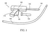
- FIG. 1illustrates in perspective view generally an insertion gun, a cannula and chest tube in accordance with one aspect of the present invention.
- FIG. 2illustrates, in side elevation view, in addition to the system of FIG. 1 , a seal in accordance with one aspect of the present invention.
- FIG. 3illustrates the gun of FIG. 1 applied to an area of tissue characteristic of a patient needing aid, with the cannula on the probe of the gun.
- FIG. 4illustrates the gun of FIG. 1 inserted partly into the patient after appropriate cuts have been made.
- FIG. 5illustrates the gun removed from the patient with the cannula remaining inserted into the patient.
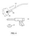
- FIG. 6illustrates the insertion of the chest tube through the cannula of FIG. 5 .
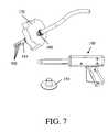
- FIG. 7illustrates the chest tube inserted into the patient through the cannula.
- FIG. 8illustrates the removal of the compliant cannula over the chest tube.
- FIG. 9illustrates the application of a sealing element over the chest tube.
- FIG. 10illustrates the sealing of the wound with the seal over the chest tube, thus completing the chest tube installation.
- FIGS. 11A-11Bshow in cut-away view one implementation of the gun of FIG. 1 , with FIG. 11B providing a detail view of the cutting tip of the gun.
- FIG. 12shows in cut-away view certain details of the implementation of FIG. 11A .
- FIG. 13illustrates in cut-away view the gun of FIG. 11A with the trigger at approximately mid-point.
- FIG. 14illustrates in more detail an implementation of the gun of FIG. 13 .
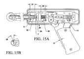
- FIG. 15Aillustrates the implementation of the gun of FIG. 11A with the trigger fully retracted.
- FIG. 15Billustrates in detail cut-away view the cutting tip of FIG. 15A .
- FIGS. 16A-16Dillustrate the eccentric nature of the cutting tip of the gun.
- FIGS. 17A-17Dillustrate cross-sectional view of various chest tubes, both in compressed and uncompressed views.
- FIGS. 18A-18Eillustrate various details of some examples of chest tubes in accordance with the present invention.
- FIGS. 19A-19Billustrate perspective and cross-sectional side views of a seal in accordance with the invention.
- FIG. 20illustrates an adhesive method for attachment of the chest tube assembly to a patient.
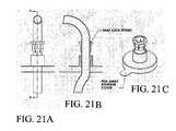
- FIGS. 21A-21Cillustrate, respectively, a side elevation view of a snap lock fitting for attachment of the chest tube to a patient, a cross-sectional side view, and a perspective view of the snap lock fitting itself.
- FIGS. 22A-22Billustrate in cross-sectional side view the attachment of the snap lock fitting of FIGS. 21A-21C to a patient.
- a chest tube insertion device 100which may also be thought of as a cutting and insertion gun, includes a housing 105 , a handle 110 with a trigger 125 , a probe tip 130 having a cutting tip 135 at the distal end thereof, a cannula 140 , a chest tube 145 and a seal 150 .
- the cutting tip 135may be of the type described in the Related Application.
- the process for inserting a chest tube according to the present inventioncan be better appreciated.
- the chest tube insertion procedure using this systemis safer, faster, and easier than other known methods.
- clinicians considering insertion of a chest tubetypically include the steps of selecting a site, preparing the patient and then draping the area, followed by anesthetizing the site.
- the anesthesiacan be of any acceptable type; one typical approach is 5 to 15 ml of 1% lidocaine delivered through a syringe and small gauge needle.
- the clinicianwill typically take the additional steps of suturing the skin on both sides of the chest tube and tying the tube in place with the tag ends of the suture; applying sterile petroleum gel over the incision to create an airtight seal and cutting notches in sterile gauze to fit around the chest tube, followed by securing the gauze and tube in place using a suitable surgical tape.
- the present inventionprovides an improvement over the standard methods of securing the chest tube in place.
- the chest tube insertion procedure in accordance with the present inventioncontinues as follows:
- the chest tube insertion device 100may be implemented in any of a variety of designs, just as the cutting tip 135 may be implemented in a variety of ways as discussed in the Related Application. Several of these implementations are described in connection with FIGS. 11A through 15 .
- FIGS. 11A-11B and 12a first implementation of the chest tube insertion device shown generally at 100 may be better appreciated.
- An eccentrically mounted circular blade 1is housed inside a bearing block 2 and is attached to the bearing block 2 by an axle 6 .
- the blade 1need not be an eccentrically mounted circular blade, but may instead be any of the forms shown in the Related Application.
- the bearing block 2is located at the distal end of a shaft or probe 3 , which is similar to the probe 130 of FIG. 1 .
- the blade 1is also connected to the distal end of an input rod 4 by a pivot pin 5 .
- a compression spring 8is constrained at a compressed height 10 , by a flange 7 at the proximal end of the input rod 4 and a wall 9 inside the mechanism housing.
- the force from the compression spring 8translates through the input rod 4 to the eccentrically mounted blade 1 through the pivot pin 5 .
- the force acting on the pivot pin 5results in a moment about the axle 6 which keeps the blade 1 recessed inside the bearing block 2 until the operator initiates a cutting event.
- an input lever or trigger 14which is similar to the trigger 125 of FIG. 1 , from a stationary position 15 , as shown in FIGS. 11A-11B and the more detailed view of FIG. 12 , through an intermediate position 16 as shown in FIG. 13 to a final position 17 shown in FIG. 15 .
- the input lever 14pivots about a lever axle 18 .
- the angular rotation of the lever 14is translated through one segment of circular gear teeth 19 mounted concentric to the lever axle 18 , to a meshing segment of circular gear teeth 20 attached to a cam 21 .
- the cam 21is allowed to rotate about a shaft 22 as it is motivated to do so by motion of the gear teeth 20 .
- the cam 21 profileis exaggerated through a pair of elongated members 23 which contact a momentum storage mass 25 through a matching pair of latches 26 which are attached to the mass 25 by pins 28 .
- the latches 26are able to rotate about the pins 28 that connect them to the mass 25 .
- the mass 25is constrained to move only longitudinally on an axis co-linear with the shaft 3 .
- Angular cam motionis translated to distal-to-proximal linear motion of the mass 25 as the cam 21 rotates from a stationary position 24 shown in FIG. 11A to a final position 29 as shown in FIG. 15 .
- the mass 25is moved rearward or toward the proximal end of the device 100 .
- Distal-to-proximal linear motion of the mass 25causes the angled outer surfaces of the matching pair of latches 26 to encounter stationary protrusions 27 .
- the protrusions 27act on the angled outer surfaces of the latches 26 so that the latches 26 rotate about their pivot pins 28 until they no longer contact the cam members 23 .
- the mass 25compresses a spring 11 from its free length 12 as depicted in FIG. 11 , as it travels proximally, to a compressed length 13 as depicted in FIG. 13 .
- the proximal to distal motion of the mass 25causes its distal most face 30 to strike the proximal end of the rod 4 .
- the mass 25 and the rod 4continue with a proximal to distal motion until the flange 7 strikes a travel limiting structure 32 .
- the proximal to distal motion of the rod 4acts on the blade 1 such that it rotates about the axle 6 , which attaches the blade 1 to the bearing block 2 .
- the blade 1rotates about the axle 6 , which connects the blade 1 to the bearing block 2 . Depicted in FIGS. 16A-D , as the blade 1 rotates, it emerges from the bearing block 2 from a stationary position to a fully exposed position when the rod 4 encounters the travel limiting structure 32 .
- the momentum storage mass 25As the momentum storage mass 25 travels in a proximal to distal direction it compresses a spring 36 constrained between a flange 39 and stationary internal structure 40 . Force stored in the spring 36 created by compressing the spring 36 to a pre-loaded height 38 acts on the mass 25 once its proximal to distal motion has been halted by the travel limiting structure 32 . The force generated by the spring 36 causes the mass 25 to move in a distal to proximal direction until equilibrium is achieved. With the mass 25 reset, the compression spring 8 that is in contact with the proximal end of the rod 4 acts on the rod 4 to move the rod 4 in a distal to proximal direction thereby recessing the blade 1 to a safe position inside the bearing block 2 .
- the operatorresets the mechanism after initiating a cutting event by releasing the input lever 14 .
- the input lever 14then returns to the stationary position 15 by means of a spring (not shown) in contact with the input lever 14 , causing the input lever 14 to rotate about the lever axle 18 .
- Motion of the lever 14causes the cam 21 to move to its stationary position 24 .
- the latches 26 attached to the mass 25are acted on by an extension spring 41 to return the latches 26 to their position 42 .
- the mechanismis now reset and ready for another operator initiated cutting event.
- an additional user controlmay be incorporated into the device 100 to hold the cutting element fully extended when actuated.
- This alternative controlallows the clinician to optionally use the device as a sharp trocar as well.
- the shaft 130is, in an least some embodiments, substantially ovate in cross section. This allows for passage of a larger bore transversely compliant cannula to be inserted between the ribs without dilating the rib cage.
- standard chest tubesare fairly diametrically compliant, across the transverse axis of the tube, and become much more compliant at body temperature. Therefore, standard chest tubes can be passed through a substantially ovate cannula.
- a larger chest tubecan be inserted with significantly less pain to the patient.
- the cannulamay be pre-formed with an ovate cross section of a less compliant material.
- Standard chest tubesare formed with uniform wall thickness. These tubes are formed with walls heavy enough to prevent kinking across the transverse axis of the tube due to longitudinal bending loads.
- the load required to pass the circular chest tube through the cannulacan be substantially reduced through the use of a tube that is preferentially more diametrically compliant, across the transverse axis, than standard tubes.
- a generally thinner walled tubewhich may for example be formed by extrusion, with walls formed with a multiplicity of longitudinal ribs, scallops or splines as shown in FIGS. 17A-17D .
- the ribsmay be on the inside or outside of the tube, and may take any of a wide variety of shapes. The space between the ribs form flexure zones, thus allowing the tube to be more diametrically compliant than a standard tube.
- Another purpose of the ribsis to provide adequate section modulus to prevent transverse kinking of the tube when bent under normal loading conditions, such as shown by the equations set forth below and shown in FIGS. 18A-18E .
- design of interior ribscould provide patent lumens, to prevent complete shut off, even when exposed to extreme loading conditions. Additionally the ribs add sufficient section to provide adequate resistance to tensile loads.
- pneumo-sealis used herein to refer to a seal that acts as a barrier to prevents the flow of fluids and gases.
- the pneumo-seal 150can be formed of a compliant material with upper flange 1900 and lower flange 1905 , and may have pressure sensitive adhesive attachment areas 1910 as shown in FIGS. 20 and 21 to adhere to and seal to the patient and the chest tube.
- the pressure sensitive seal or barrier formed by the pneumo-sealis accomplished without stitches or sutures.
- the pneumo-sealmay be pre-loaded and reside on the cannula 140 or may be used as a separate device.
- the sealing structure 150is shown in FIG. 20 as having a generally disk-shaped lower portion, the bottom surface of which is covered by adhesive for attaching the sealing structure 150 to the patient. See also FIG. 10 .
- the adhesive bottom surface of the sealing structure 150is protected by a cover which can be readily peeled away when ready to be attached to the patient. See FIGS. 9 and 21C .
- the generally disk-shaped lower portion of the sealing structure 150includes a central aperture through which the chest tube 145 passes.
- the sealing structurefurther includes two adhesive patches 1910 for attaching the sealing structure 150 to the chest tube 145 , the adhesive patches 1910 being attached to the lower portion along diametrically opposed parts of the circumference of the central aperture.
- the adhesive patches 1910are configured to fold up along the length of the chest tube 145 from the plane of the generally disk-shaped lower portion, each adhesive patch wrapping widthwise only partially around the circumference of the chest tube.
- the pneumo-seal device 150may have a fitting 2200 that mates to a matching fitting integrally formed with the chest tube or, as shown in FIG. 22B , provided as a snap-lock fitting added to the chest tube.
- the purpose of the fittingis to mechanically attach the tube to the patient patch and to form an air-tight seal.
- the basic configuration of the pneumo-seal 150can also be used for other cannulations into the body such as central venous lines and other drainage tubes.
- the devicemay be molded from a transparent material, such as Pebax, to allow visualization of the wound through the device.
- the advantages of the pneumo-seal deviceinclude that it is faster than faster than cutting bandages, requires no use of scissors, is faster than suturing or tying, requires no needles, does not require petroleum gel to form seal (thus allowing use of standard wound dressing tapes.
- FIG. 22Amechanical sealing ribs may also replace the adhesive contacting tube.
- the sealing structure 150is shown to have a cylindrical upper portion with a plurality of circumferential ribs on the inner surface of the cylindrical upper portion.
- the chest tube 145is shown to be sufficiently compliant to conform to the ribbed inner surface of the sealing structure 150 .
- the plurality of annular ribsare spaced along the length of the generally cylindrical upper portion.
- the basic configuration of the pneumo-seal 150can also be used for other cannulations into the body such as central venous lines and other drainage tubes.
- the devicemay be molded from a transparent material, such as Pebax, to allow visualization of the wound through the device.
- Pebaxa transparent material
- the advantages of the pneumo-seal deviceinclude that it is faster than cutting bandages, requires no use of scissors, is faster than suturing or tying, requires no needles, does not require petroleum gel to form a seal (thus allowing use of standard wound dressing tapes).
Landscapes
- Health & Medical Sciences (AREA)
- Surgery (AREA)
- Life Sciences & Earth Sciences (AREA)
- Heart & Thoracic Surgery (AREA)
- Nuclear Medicine, Radiotherapy & Molecular Imaging (AREA)
- Pathology (AREA)
- Engineering & Computer Science (AREA)
- Biomedical Technology (AREA)
- Medical Informatics (AREA)
- Molecular Biology (AREA)
- Animal Behavior & Ethology (AREA)
- General Health & Medical Sciences (AREA)
- Public Health (AREA)
- Veterinary Medicine (AREA)
- Gastroenterology & Hepatology (AREA)
- Surgical Instruments (AREA)
Abstract
Description
- 1. Make an incision through skin to the pleural space with the chest tube insertion device, or gun,100. Start by placing a
cannula 140 over the probe tip orshaft 130 of thedevice 100 until thecutting tip 135 extends beyond thecannula 140. - 2. Place the
device 100 against the patient'starget tissue 170 as shown inFIG. 3 . Visually aligning theshaft 130 of the device in the desired direction. Firmly press thedistal tip 135 into the skin and actuate thetrigger 125. Actuation of the trigger will initiate a cutting event, creating an incision175, as shown inFIG. 4 . Each cutting event will cut approximately 1 mm in depth as long as the cutting tip is maintained appropriately against thetissue 170. As thedevice 100 cuts through skin, thedevice 100 may be used as a blunt dissection device, and may be thought of as a blunt tip obturator. - 3. Once the tip of the
probe 130 extends into the pleural cavity in the desired amount, the cannula will also extend into the cavity as shown inFIG. 4 . Withdrawal of thegun 100 from the incision175 can be achieved while leaving thecannula 140 in place within the patient as shown inFIG. 5 . - 4. As shown best in
FIG. 6 , introduce thedistal tip 600 of thechest tube 145 into thecannula 140. - 5. Advance the
tube 145 until all of the transverse drain holes700 of thechest tube 145 are within the pleural space, as shown inFIG. 7 . - 6. Withdraw the
cannula 140 over thechest tube 145 while holding thechest tube 145 in place, best shown inFIG. 8 .
- 1. Make an incision through skin to the pleural space with the chest tube insertion device, or gun,100. Start by placing a
- 7. Place the sealing
structure 150 over thechest tube 145 and slide the sealing structure down the chest tube towards thetissue 170. Remove a protective cover from an adhesive lower surface of the sealingstructure 150 and attach the sealingstructure 150 to thetissue 170. The lower surface of the sealingstructure 150 is conformed to and adhered to thetissue 170. SeeFIGS. 9 and 10 .
- 7. Place the sealing
Claims (13)
Priority Applications (1)
| Application Number | Priority Date | Filing Date | Title |
|---|---|---|---|
| US10/770,829US7811293B2 (en) | 2003-01-31 | 2004-02-02 | System and method for rapid placement of chest tubes |
Applications Claiming Priority (3)
| Application Number | Priority Date | Filing Date | Title |
|---|---|---|---|
| US44432603P | 2003-01-31 | 2003-01-31 | |
| US44434503P | 2003-01-31 | 2003-01-31 | |
| US10/770,829US7811293B2 (en) | 2003-01-31 | 2004-02-02 | System and method for rapid placement of chest tubes |
Publications (2)
| Publication Number | Publication Date |
|---|---|
| US20050273116A1 US20050273116A1 (en) | 2005-12-08 |
| US7811293B2true US7811293B2 (en) | 2010-10-12 |
Family
ID=35450019
Family Applications (1)
| Application Number | Title | Priority Date | Filing Date |
|---|---|---|---|
| US10/770,829Expired - Fee RelatedUS7811293B2 (en) | 2003-01-31 | 2004-02-02 | System and method for rapid placement of chest tubes |
Country Status (1)
| Country | Link |
|---|---|
| US (1) | US7811293B2 (en) |
Cited By (11)
| Publication number | Priority date | Publication date | Assignee | Title |
|---|---|---|---|---|
| US20090264833A1 (en)* | 2008-01-25 | 2009-10-22 | Clear Catheter Systems, Llc | Methods and Devices to Clear Obstructions from Medical Tubes |
| US7951243B2 (en) | 2008-01-25 | 2011-05-31 | Clear Catheter Systems, Inc. | Methods and devices to clear obstructions from medical tubes |
| US8702662B2 (en) | 2003-05-02 | 2014-04-22 | Clearflow, Inc. | Body-space drainage-tube debris removal |
| EP2889012A1 (en) | 2013-12-26 | 2015-07-01 | Critical Innovations, LLC | Percutaneous access pathway system |
| US9616203B2 (en) | 2012-08-07 | 2017-04-11 | Critical Innovations, LLC | Method and device for simultaneously documenting and treating tension pneumothorax and/or hemothorax |
| EP3459476A1 (en) | 2017-09-22 | 2019-03-27 | Critical Innovations, LLC | Percutaneous access pathway system |
| US10471189B2 (en) | 2014-02-17 | 2019-11-12 | Clearflow, Inc. | Medical tube clearance device |
| WO2020076636A1 (en)* | 2018-10-08 | 2020-04-16 | Chris Salvino | Actuating scalpel device |
| WO2020113206A1 (en)* | 2018-11-30 | 2020-06-04 | Chris Salvino | Chest tube membrane |
| US10974023B2 (en) | 2014-02-17 | 2021-04-13 | Clearflow, Inc. | Medical tube clearance |
| US11491303B2 (en) | 2020-11-17 | 2022-11-08 | Clearflow, Inc. | Medical tube clearance device |
Families Citing this family (8)
| Publication number | Priority date | Publication date | Assignee | Title |
|---|---|---|---|---|
| US7811293B2 (en)* | 2003-01-31 | 2010-10-12 | Philip J. Simpson | System and method for rapid placement of chest tubes |
| US20070038180A1 (en)* | 2005-08-12 | 2007-02-15 | Sinha Anil K | Apparatus and methods for safe and efficient placement of chest tubes |
| US8652090B2 (en)* | 2006-05-18 | 2014-02-18 | Cannuflow, Inc. | Anti-extravasation surgical portal plug |
| AU2008239409B2 (en)* | 2007-04-11 | 2013-09-19 | Covidien Lp | Visualized entry trocar with moving blade |
| SG11201403027VA (en)* | 2011-12-15 | 2014-07-30 | Singapore Health Serv Pte Ltd | Device and method for in-office unsedated tracheoesophageal puncture (tep) |
| CN103933623A (en)* | 2013-01-18 | 2014-07-23 | 夏晖 | Battlefield dual-purpose chest drainage device |
| US20200107857A1 (en)* | 2018-10-08 | 2020-04-09 | Chris Salvino | Chest tube sheath |
| IT202000018193A1 (en)* | 2020-07-28 | 2022-01-28 | Redax S P A | INTRODUCER DEVICE FOR PERCUTANEOUS INTRODUCTION OF DRAINAGE TUBES, PARTICULARLY CHEST DRAINAGE TUBES, IMPROVED. |
Citations (35)
| Publication number | Priority date | Publication date | Assignee | Title |
|---|---|---|---|---|
| US3237624A (en)* | 1962-03-05 | 1966-03-01 | Medex Inc | Drainage bag |
| US4221215A (en)* | 1979-04-19 | 1980-09-09 | Isidore Mandelbaum | Anchoring and occluding surgical dressing |
| US4439189A (en)* | 1981-06-18 | 1984-03-27 | Bentley Laboratories, Inc. | Pleural drainage system |
| US4716901A (en)* | 1984-09-27 | 1988-01-05 | Pratt Burnerd International Limited | Surgical appliance for forming an opening through the skin |
| US4778446A (en)* | 1983-07-14 | 1988-10-18 | Squibb & Sons Inc | Wound irrigation and/or drainage device |
| US5045052A (en)* | 1988-11-15 | 1991-09-03 | Sans Jose V | Sealing device for controlling ileo-colostomies |
| US5098392A (en) | 1991-06-28 | 1992-03-24 | Fleischhacker John J | Locking dilator for peel away introducer sheath |
| EP0488332A2 (en) | 1990-11-29 | 1992-06-03 | Stabilus GmbH | A telescopically length variable steering column |
| US5221263A (en) | 1992-07-30 | 1993-06-22 | Gesco International, Inc. | Catheter emplacement apparatus |
| US5232453A (en)* | 1989-07-14 | 1993-08-03 | E. R. Squibb & Sons, Inc. | Catheter holder |
| US5389080A (en)* | 1990-07-26 | 1995-02-14 | Yoon; Inbae | Endoscopic portal for use in endoscopic procedures and methods therefor |
| US5429598A (en) | 1994-04-19 | 1995-07-04 | Applied Medical Resources Corporation | Surgical access device and procedure |
| CN2207149Y (en) | 1994-11-17 | 1995-09-13 | 姜小波 | Puncture needle sleeve |
| US5478333A (en) | 1994-03-04 | 1995-12-26 | Asherman, Jr.; Richard E. | Medical dressing for treating open chest injuries |
| US5545179A (en) | 1995-07-21 | 1996-08-13 | Ethicon Endo-Surgery, Inc. | Endoscopic access assembly |
| US5545517A (en) | 1994-03-15 | 1996-08-13 | The United States Of America As Represented By The Secretary Of The Navy | Selective metal ion detection using a photoluminescent indicator binding to a macromolecule-metal ion complex |
| US5685859A (en)* | 1994-06-02 | 1997-11-11 | Nikomed Aps | Device for fixating a drainage tube and a drainage tube assembly |
| US5797882A (en) | 1996-08-23 | 1998-08-25 | Becton Dickinson And Company | Arterial catheter and catheter/needle assembly with improved flow characteristics and method for its use |
| US5807341A (en) | 1996-12-11 | 1998-09-15 | Team Medical Llc | Medical catheter dressing device |
| US5897531A (en)* | 1994-01-07 | 1999-04-27 | Amirana; Omar | Adhesive surgical retaining device |
| US5919203A (en) | 1998-01-21 | 1999-07-06 | Royce H. Husted | Powered surgical tool |
| US6045535A (en)* | 1996-06-13 | 2000-04-04 | One Way Ocular Technology Ltd. | Surgical sealing sleeve |
| US6056730A (en)* | 1997-02-26 | 2000-05-02 | Medela Holding Ag | Device and method for the drainage of fluids |
| US6056766A (en)* | 1998-06-09 | 2000-05-02 | Thompson; Ronald J. | Stabilized trocar, and method of using same |
| US6074380A (en)* | 1995-09-15 | 2000-06-13 | Btg International Limited | Device and method for transcutaneous surgery |
| US6110154A (en)* | 1996-10-08 | 2000-08-29 | Hakko Electric Machine Works, Co. Ltd. | Valve and valved trocar jacket tube |
| US20020042607A1 (en)* | 2000-10-11 | 2002-04-11 | Popcab, Llc | Instrument stabilizer for through-a-port surgery |
| US20020133168A1 (en)* | 2001-03-16 | 2002-09-19 | Smedley Gregory T. | Applicator and methods for placing a trabecular shunt for glaucoma treatment |
| US20020161377A1 (en)* | 2001-04-27 | 2002-10-31 | Dmitry Rabkin | Apparatus for delivering, repositioning and/or retrieving self-expanding stents |
| WO2003008020A1 (en) | 2001-07-17 | 2003-01-30 | Yale University | Tunneler-needle combination for tunneled catheter placement |
| US20030088245A1 (en)* | 2001-11-02 | 2003-05-08 | Arthrocare Corporation | Methods and apparatus for electrosurgical ventriculostomy |
| US20030233073A1 (en)* | 2000-10-12 | 2003-12-18 | Purow Benjamin Warren | Sheath device with dressing for prevention of pneumothorax |
| US6811546B1 (en)* | 2000-08-25 | 2004-11-02 | Origin Medsystems, Inc. | Endoscopic surgical access port and method |
| US20050273116A1 (en)* | 2003-01-31 | 2005-12-08 | Simpson Philip J | System and method for rapid placement of chest tubes |
| US7377898B2 (en)* | 2003-08-22 | 2008-05-27 | Applied Medical Resources Corporation | Wound retraction apparatus and method |
- 2004
- 2004-02-02USUS10/770,829patent/US7811293B2/ennot_activeExpired - Fee Related
Patent Citations (38)
| Publication number | Priority date | Publication date | Assignee | Title |
|---|---|---|---|---|
| US3237624A (en)* | 1962-03-05 | 1966-03-01 | Medex Inc | Drainage bag |
| US4221215A (en)* | 1979-04-19 | 1980-09-09 | Isidore Mandelbaum | Anchoring and occluding surgical dressing |
| US4439189A (en)* | 1981-06-18 | 1984-03-27 | Bentley Laboratories, Inc. | Pleural drainage system |
| US4778446A (en)* | 1983-07-14 | 1988-10-18 | Squibb & Sons Inc | Wound irrigation and/or drainage device |
| US4716901A (en)* | 1984-09-27 | 1988-01-05 | Pratt Burnerd International Limited | Surgical appliance for forming an opening through the skin |
| US5045052A (en)* | 1988-11-15 | 1991-09-03 | Sans Jose V | Sealing device for controlling ileo-colostomies |
| US5232453A (en)* | 1989-07-14 | 1993-08-03 | E. R. Squibb & Sons, Inc. | Catheter holder |
| US5389080A (en)* | 1990-07-26 | 1995-02-14 | Yoon; Inbae | Endoscopic portal for use in endoscopic procedures and methods therefor |
| EP0488332A2 (en) | 1990-11-29 | 1992-06-03 | Stabilus GmbH | A telescopically length variable steering column |
| US5098392A (en) | 1991-06-28 | 1992-03-24 | Fleischhacker John J | Locking dilator for peel away introducer sheath |
| US5221263A (en) | 1992-07-30 | 1993-06-22 | Gesco International, Inc. | Catheter emplacement apparatus |
| US5897531A (en)* | 1994-01-07 | 1999-04-27 | Amirana; Omar | Adhesive surgical retaining device |
| US5478333A (en) | 1994-03-04 | 1995-12-26 | Asherman, Jr.; Richard E. | Medical dressing for treating open chest injuries |
| US5545517A (en) | 1994-03-15 | 1996-08-13 | The United States Of America As Represented By The Secretary Of The Navy | Selective metal ion detection using a photoluminescent indicator binding to a macromolecule-metal ion complex |
| US5429598A (en) | 1994-04-19 | 1995-07-04 | Applied Medical Resources Corporation | Surgical access device and procedure |
| US5685859A (en)* | 1994-06-02 | 1997-11-11 | Nikomed Aps | Device for fixating a drainage tube and a drainage tube assembly |
| CN2207149Y (en) | 1994-11-17 | 1995-09-13 | 姜小波 | Puncture needle sleeve |
| US5545179A (en) | 1995-07-21 | 1996-08-13 | Ethicon Endo-Surgery, Inc. | Endoscopic access assembly |
| US6074380A (en)* | 1995-09-15 | 2000-06-13 | Btg International Limited | Device and method for transcutaneous surgery |
| US6045535A (en)* | 1996-06-13 | 2000-04-04 | One Way Ocular Technology Ltd. | Surgical sealing sleeve |
| US5797882A (en) | 1996-08-23 | 1998-08-25 | Becton Dickinson And Company | Arterial catheter and catheter/needle assembly with improved flow characteristics and method for its use |
| US6110154A (en)* | 1996-10-08 | 2000-08-29 | Hakko Electric Machine Works, Co. Ltd. | Valve and valved trocar jacket tube |
| US5807341A (en) | 1996-12-11 | 1998-09-15 | Team Medical Llc | Medical catheter dressing device |
| US6056730A (en)* | 1997-02-26 | 2000-05-02 | Medela Holding Ag | Device and method for the drainage of fluids |
| US5919203A (en) | 1998-01-21 | 1999-07-06 | Royce H. Husted | Powered surgical tool |
| US6056766A (en)* | 1998-06-09 | 2000-05-02 | Thompson; Ronald J. | Stabilized trocar, and method of using same |
| US7276075B1 (en)* | 2000-08-25 | 2007-10-02 | Origin Medsystems, Inc. | Endoscopic surgical access port and method |
| US6811546B1 (en)* | 2000-08-25 | 2004-11-02 | Origin Medsystems, Inc. | Endoscopic surgical access port and method |
| US6579281B2 (en)* | 2000-10-11 | 2003-06-17 | Popcab, Llc | Instrument stabilizer for through-a-port surgery |
| US20020042607A1 (en)* | 2000-10-11 | 2002-04-11 | Popcab, Llc | Instrument stabilizer for through-a-port surgery |
| US20030233073A1 (en)* | 2000-10-12 | 2003-12-18 | Purow Benjamin Warren | Sheath device with dressing for prevention of pneumothorax |
| US7244245B2 (en)* | 2000-10-12 | 2007-07-17 | Benjamin Purow | Sheath device with dressing for prevention of pneumothorax. |
| US20020133168A1 (en)* | 2001-03-16 | 2002-09-19 | Smedley Gregory T. | Applicator and methods for placing a trabecular shunt for glaucoma treatment |
| US20020161377A1 (en)* | 2001-04-27 | 2002-10-31 | Dmitry Rabkin | Apparatus for delivering, repositioning and/or retrieving self-expanding stents |
| WO2003008020A1 (en) | 2001-07-17 | 2003-01-30 | Yale University | Tunneler-needle combination for tunneled catheter placement |
| US20030088245A1 (en)* | 2001-11-02 | 2003-05-08 | Arthrocare Corporation | Methods and apparatus for electrosurgical ventriculostomy |
| US20050273116A1 (en)* | 2003-01-31 | 2005-12-08 | Simpson Philip J | System and method for rapid placement of chest tubes |
| US7377898B2 (en)* | 2003-08-22 | 2008-05-27 | Applied Medical Resources Corporation | Wound retraction apparatus and method |
Non-Patent Citations (1)
| Title |
|---|
| European Search Report issued Mar. 17, 2010 in corresponding EP 04707425. |
Cited By (35)
| Publication number | Priority date | Publication date | Assignee | Title |
|---|---|---|---|---|
| US10667884B2 (en) | 2003-05-02 | 2020-06-02 | Clearflow, Inc. | Body-space drainage-tube debris removal |
| US8702662B2 (en) | 2003-05-02 | 2014-04-22 | Clearflow, Inc. | Body-space drainage-tube debris removal |
| US9597159B2 (en) | 2003-05-02 | 2017-03-21 | Clearflow, Inc. | Body-space drainage-tube debris removal |
| US10149960B2 (en) | 2008-01-25 | 2018-12-11 | Clearflow, Inc. | Methods and devices to clear obstructions from medical tubes |
| US7951243B2 (en) | 2008-01-25 | 2011-05-31 | Clear Catheter Systems, Inc. | Methods and devices to clear obstructions from medical tubes |
| US8246752B2 (en) | 2008-01-25 | 2012-08-21 | Clear Catheter Systems, Inc. | Methods and devices to clear obstructions from medical tubes |
| US8951355B2 (en) | 2008-01-25 | 2015-02-10 | Clearflow, Inc. | Methods and devices to clear obstructions from medical tubes |
| US8048233B2 (en) | 2008-01-25 | 2011-11-01 | Clear Catheter Systems, Inc. | Methods and devices to clear obstructions from medical tubes |
| US10898674B2 (en) | 2008-01-25 | 2021-01-26 | Clearflow, Inc. | Methods and devices to clear obstructions from medical tubes |
| US20090264833A1 (en)* | 2008-01-25 | 2009-10-22 | Clear Catheter Systems, Llc | Methods and Devices to Clear Obstructions from Medical Tubes |
| US8388759B2 (en) | 2008-01-25 | 2013-03-05 | Clear Catheter Systems, Inc. | Methods and devices to clear obstructions from medical tubes |
| US11364326B2 (en) | 2012-08-07 | 2022-06-21 | Critical Innovations, LLC | Method and device for simultaneously documenting and treating tension pneumothorax and/or hemothorax |
| US9616203B2 (en) | 2012-08-07 | 2017-04-11 | Critical Innovations, LLC | Method and device for simultaneously documenting and treating tension pneumothorax and/or hemothorax |
| US12419999B2 (en) | 2012-08-07 | 2025-09-23 | Critical Innovations, LLC | Method and device for simultaneously documenting and treating tension pneumothorax and/or hemothorax |
| US10314952B2 (en) | 2012-08-07 | 2019-06-11 | Critical Innovations, LLC | Method and device for simultaneously documenting and treating tension pneumothorax and/or hemothorax |
| US12005165B2 (en) | 2012-08-07 | 2024-06-11 | Critical Innovations, LLC | Method and device for simultaneously documenting and treating tension pneumothorax and/or hemothorax |
| US10864356B2 (en) | 2013-12-26 | 2020-12-15 | Critical Innovations, LLC | Percutaneous access pathway system and method |
| US12263320B2 (en) | 2013-12-26 | 2025-04-01 | Critical Innovations Llc | Percutaneous access pathway system and method |
| US10046147B2 (en) | 2013-12-26 | 2018-08-14 | Critical Innovations, LLC | Percutaneous access pathway system and method |
| US11865281B2 (en) | 2013-12-26 | 2024-01-09 | Critical Innovations, LLC | Percutaneous access pathway system and method |
| EP2889012A1 (en) | 2013-12-26 | 2015-07-01 | Critical Innovations, LLC | Percutaneous access pathway system |
| US12171952B2 (en) | 2014-02-17 | 2024-12-24 | Clearflow, Inc. | Medical tube clearance device |
| US10471189B2 (en) | 2014-02-17 | 2019-11-12 | Clearflow, Inc. | Medical tube clearance device |
| US10974023B2 (en) | 2014-02-17 | 2021-04-13 | Clearflow, Inc. | Medical tube clearance |
| EP4059457A1 (en) | 2017-09-22 | 2022-09-21 | Critical Innovations, LLC | Percutaneous access pathway system |
| US11406809B2 (en) | 2017-09-22 | 2022-08-09 | Critical Innovations, LLC | Percutaneous access pathway system |
| EP3782563A1 (en) | 2017-09-22 | 2021-02-24 | Critical Innovations, LLC | Percutaneous access pathway system |
| US10814119B2 (en) | 2017-09-22 | 2020-10-27 | Critical Innovations, LLC | Percutaneous access pathway system |
| US12324894B2 (en) | 2017-09-22 | 2025-06-10 | Critical Innovations Llc | Percutaneous access pathway system |
| EP3459476A1 (en) | 2017-09-22 | 2019-03-27 | Critical Innovations, LLC | Percutaneous access pathway system |
| EP3863538A4 (en)* | 2018-10-08 | 2022-10-12 | Chris Salvino | Actuating scalpel device |
| WO2020076636A1 (en)* | 2018-10-08 | 2020-04-16 | Chris Salvino | Actuating scalpel device |
| WO2020113206A1 (en)* | 2018-11-30 | 2020-06-04 | Chris Salvino | Chest tube membrane |
| US11491303B2 (en) | 2020-11-17 | 2022-11-08 | Clearflow, Inc. | Medical tube clearance device |
| US11724062B2 (en) | 2020-11-17 | 2023-08-15 | Clearflow, Inc. | Medical tube clearance device |
Also Published As
| Publication number | Publication date |
|---|---|
| US20050273116A1 (en) | 2005-12-08 |
Similar Documents
| Publication | Publication Date | Title |
|---|---|---|
| US7811293B2 (en) | System and method for rapid placement of chest tubes | |
| CN100515512C (en) | Safety trocar with progressive cutting tip guard and air jet tissue deflector | |
| CN100415154C (en) | Medical device used to provide access | |
| JP4290388B2 (en) | Trocar with obturator and reinforced obturator shaft | |
| EP2311394B1 (en) | Cannulated arthroscopic knife | |
| AU698515B2 (en) | Trocar having improved tip configuration | |
| JP5424722B2 (en) | Bladed / bladeless obturator for use in a surgical trocar assembly | |
| AU2005200103B2 (en) | Method for accessing an operating space | |
| US6830578B2 (en) | Trocar | |
| US7540875B2 (en) | Surgical cutting tool with automatically retractable blade assembly | |
| JPH11504234A (en) | Shrinkable safety insert with laterally expandable spring strip | |
| US10779857B2 (en) | Device and method for access to interior body regions | |
| CN107361829B (en) | Self-retraction puncture core structure | |
| CA2514857C (en) | System and method for rapid placement of chest tubes | |
| US20040193113A1 (en) | Expandable bore injection needle | |
| HK1090271B (en) | System for rapid placement of chest tubes | |
| CA2518043A1 (en) | Insufflator and method of use |
Legal Events
| Date | Code | Title | Description |
|---|---|---|---|
| AS | Assignment | Owner name:FLEX PARTNERS, INC., CALIFORNIA Free format text:ASSIGNMENT OF ASSIGNORS INTEREST;ASSIGNORS:SIMPSON, PHILIP J.;GILLESPIE, WALTER DEAN;MATSUURA, DAVID G.;AND OTHERS;REEL/FRAME:016453/0190 Effective date:20050824 | |
| AS | Assignment | Owner name:SIMPSON, PHILIP J., CALIFORNIA Free format text:ASSIGNMENT OF ASSIGNORS INTEREST;ASSIGNOR:FLEX PARTNERS, INC.;REEL/FRAME:016490/0370 Effective date:20050824 Owner name:SALVINO, CHRIS, ILLINOIS Free format text:ASSIGNMENT OF ASSIGNORS INTEREST;ASSIGNOR:FLEX PARTNERS, INC.;REEL/FRAME:016490/0370 Effective date:20050824 Owner name:GILLESPIE, WALTER DEAN, CALIFORNIA Free format text:ASSIGNMENT OF ASSIGNORS INTEREST;ASSIGNOR:FLEX PARTNERS, INC.;REEL/FRAME:016490/0370 Effective date:20050824 Owner name:MATSUURA, DAVID G., CALIFORNIA Free format text:ASSIGNMENT OF ASSIGNORS INTEREST;ASSIGNOR:FLEX PARTNERS, INC.;REEL/FRAME:016490/0370 Effective date:20050824 | |
| STCF | Information on status: patent grant | Free format text:PATENTED CASE | |
| FPAY | Fee payment | Year of fee payment:4 | |
| MAFP | Maintenance fee payment | Free format text:PAYMENT OF MAINTENANCE FEE, 8TH YR, SMALL ENTITY (ORIGINAL EVENT CODE: M2552) Year of fee payment:8 | |
| FEPP | Fee payment procedure | Free format text:MAINTENANCE FEE REMINDER MAILED (ORIGINAL EVENT CODE: REM.); ENTITY STATUS OF PATENT OWNER: SMALL ENTITY | |
| LAPS | Lapse for failure to pay maintenance fees | Free format text:PATENT EXPIRED FOR FAILURE TO PAY MAINTENANCE FEES (ORIGINAL EVENT CODE: EXP.); ENTITY STATUS OF PATENT OWNER: SMALL ENTITY | |
| STCH | Information on status: patent discontinuation | Free format text:PATENT EXPIRED DUE TO NONPAYMENT OF MAINTENANCE FEES UNDER 37 CFR 1.362 | |
| FP | Lapsed due to failure to pay maintenance fee | Effective date:20221012 |