US7811252B2 - Dosage control device - Google Patents
Dosage control deviceDownload PDFInfo
- Publication number
- US7811252B2 US7811252B2US11/688,573US68857307AUS7811252B2US 7811252 B2US7811252 B2US 7811252B2US 68857307 AUS68857307 AUS 68857307AUS 7811252 B2US7811252 B2US 7811252B2
- Authority
- US
- United States
- Prior art keywords
- dispensing chamber
- plunger
- fuse
- controller
- injection device
- Prior art date
- Legal status (The legal status is an assumption and is not a legal conclusion. Google has not performed a legal analysis and makes no representation as to the accuracy of the status listed.)
- Active
Links
- 238000002347injectionMethods0.000abstract3
- 239000007924injectionSubstances0.000abstract3
- 230000001954sterilising effectEffects0.000abstract1
- 238000004659sterilization and disinfectionMethods0.000abstract1
- 239000000126substanceSubstances0.000abstract1
Images


Classifications
- A—HUMAN NECESSITIES
- A61—MEDICAL OR VETERINARY SCIENCE; HYGIENE
- A61M—DEVICES FOR INTRODUCING MEDIA INTO, OR ONTO, THE BODY; DEVICES FOR TRANSDUCING BODY MEDIA OR FOR TAKING MEDIA FROM THE BODY; DEVICES FOR PRODUCING OR ENDING SLEEP OR STUPOR
- A61M35/00—Devices for applying media, e.g. remedies, on the human body
- A61M35/003—Portable hand-held applicators having means for dispensing or spreading integral media
- A—HUMAN NECESSITIES
- A61—MEDICAL OR VETERINARY SCIENCE; HYGIENE
- A61F—FILTERS IMPLANTABLE INTO BLOOD VESSELS; PROSTHESES; DEVICES PROVIDING PATENCY TO, OR PREVENTING COLLAPSING OF, TUBULAR STRUCTURES OF THE BODY, e.g. STENTS; ORTHOPAEDIC, NURSING OR CONTRACEPTIVE DEVICES; FOMENTATION; TREATMENT OR PROTECTION OF EYES OR EARS; BANDAGES, DRESSINGS OR ABSORBENT PADS; FIRST-AID KITS
- A61F9/00—Methods or devices for treatment of the eyes; Devices for putting in contact-lenses; Devices to correct squinting; Apparatus to guide the blind; Protective devices for the eyes, carried on the body or in the hand
- A61F9/0008—Introducing ophthalmic products into the ocular cavity or retaining products therein
- A61F9/0017—Introducing ophthalmic products into the ocular cavity or retaining products therein implantable in, or in contact with, the eye, e.g. ocular inserts
- A—HUMAN NECESSITIES
- A61—MEDICAL OR VETERINARY SCIENCE; HYGIENE
- A61F—FILTERS IMPLANTABLE INTO BLOOD VESSELS; PROSTHESES; DEVICES PROVIDING PATENCY TO, OR PREVENTING COLLAPSING OF, TUBULAR STRUCTURES OF THE BODY, e.g. STENTS; ORTHOPAEDIC, NURSING OR CONTRACEPTIVE DEVICES; FOMENTATION; TREATMENT OR PROTECTION OF EYES OR EARS; BANDAGES, DRESSINGS OR ABSORBENT PADS; FIRST-AID KITS
- A61F9/00—Methods or devices for treatment of the eyes; Devices for putting in contact-lenses; Devices to correct squinting; Apparatus to guide the blind; Protective devices for the eyes, carried on the body or in the hand
- A61F9/007—Methods or devices for eye surgery
- A—HUMAN NECESSITIES
- A61—MEDICAL OR VETERINARY SCIENCE; HYGIENE
- A61M—DEVICES FOR INTRODUCING MEDIA INTO, OR ONTO, THE BODY; DEVICES FOR TRANSDUCING BODY MEDIA OR FOR TAKING MEDIA FROM THE BODY; DEVICES FOR PRODUCING OR ENDING SLEEP OR STUPOR
- A61M5/00—Devices for bringing media into the body in a subcutaneous, intra-vascular or intramuscular way; Accessories therefor, e.g. filling or cleaning devices, arm-rests
- A61M5/14—Infusion devices, e.g. infusing by gravity; Blood infusion; Accessories therefor
- A61M5/142—Pressure infusion, e.g. using pumps
- A61M5/14212—Pumping with an aspiration and an expulsion action
- A61M5/14224—Diaphragm type
- A—HUMAN NECESSITIES
- A61—MEDICAL OR VETERINARY SCIENCE; HYGIENE
- A61M—DEVICES FOR INTRODUCING MEDIA INTO, OR ONTO, THE BODY; DEVICES FOR TRANSDUCING BODY MEDIA OR FOR TAKING MEDIA FROM THE BODY; DEVICES FOR PRODUCING OR ENDING SLEEP OR STUPOR
- A61M5/00—Devices for bringing media into the body in a subcutaneous, intra-vascular or intramuscular way; Accessories therefor, e.g. filling or cleaning devices, arm-rests
- A61M5/178—Syringes
- A61M5/20—Automatic syringes, e.g. with automatically actuated piston rod, with automatic needle injection, filling automatically
- A—HUMAN NECESSITIES
- A61—MEDICAL OR VETERINARY SCIENCE; HYGIENE
- A61M—DEVICES FOR INTRODUCING MEDIA INTO, OR ONTO, THE BODY; DEVICES FOR TRANSDUCING BODY MEDIA OR FOR TAKING MEDIA FROM THE BODY; DEVICES FOR PRODUCING OR ENDING SLEEP OR STUPOR
- A61M5/00—Devices for bringing media into the body in a subcutaneous, intra-vascular or intramuscular way; Accessories therefor, e.g. filling or cleaning devices, arm-rests
- A61M5/178—Syringes
- A61M5/31—Details
- A61M5/315—Pistons; Piston-rods; Guiding, blocking or restricting the movement of the rod or piston; Appliances on the rod for facilitating dosing ; Dosing mechanisms
- A61M5/31525—Dosing
- A—HUMAN NECESSITIES
- A61—MEDICAL OR VETERINARY SCIENCE; HYGIENE
- A61M—DEVICES FOR INTRODUCING MEDIA INTO, OR ONTO, THE BODY; DEVICES FOR TRANSDUCING BODY MEDIA OR FOR TAKING MEDIA FROM THE BODY; DEVICES FOR PRODUCING OR ENDING SLEEP OR STUPOR
- A61M5/00—Devices for bringing media into the body in a subcutaneous, intra-vascular or intramuscular way; Accessories therefor, e.g. filling or cleaning devices, arm-rests
- A61M5/44—Devices for bringing media into the body in a subcutaneous, intra-vascular or intramuscular way; Accessories therefor, e.g. filling or cleaning devices, arm-rests having means for cooling or heating the devices or media
- A—HUMAN NECESSITIES
- A61—MEDICAL OR VETERINARY SCIENCE; HYGIENE
- A61M—DEVICES FOR INTRODUCING MEDIA INTO, OR ONTO, THE BODY; DEVICES FOR TRANSDUCING BODY MEDIA OR FOR TAKING MEDIA FROM THE BODY; DEVICES FOR PRODUCING OR ENDING SLEEP OR STUPOR
- A61M2205/00—General characteristics of the apparatus
- A61M2205/02—General characteristics of the apparatus characterised by a particular materials
- A61M2205/0244—Micromachined materials, e.g. made from silicon wafers, microelectromechanical systems [MEMS] or comprising nanotechnology
- A—HUMAN NECESSITIES
- A61—MEDICAL OR VETERINARY SCIENCE; HYGIENE
- A61M—DEVICES FOR INTRODUCING MEDIA INTO, OR ONTO, THE BODY; DEVICES FOR TRANSDUCING BODY MEDIA OR FOR TAKING MEDIA FROM THE BODY; DEVICES FOR PRODUCING OR ENDING SLEEP OR STUPOR
- A61M2205/00—General characteristics of the apparatus
- A61M2205/33—Controlling, regulating or measuring
- A61M2205/3368—Temperature
- A—HUMAN NECESSITIES
- A61—MEDICAL OR VETERINARY SCIENCE; HYGIENE
- A61M—DEVICES FOR INTRODUCING MEDIA INTO, OR ONTO, THE BODY; DEVICES FOR TRANSDUCING BODY MEDIA OR FOR TAKING MEDIA FROM THE BODY; DEVICES FOR PRODUCING OR ENDING SLEEP OR STUPOR
- A61M2205/00—General characteristics of the apparatus
- A61M2205/36—General characteristics of the apparatus related to heating or cooling
- A61M2205/3653—General characteristics of the apparatus related to heating or cooling by Joule effect, i.e. electric resistance
- A—HUMAN NECESSITIES
- A61—MEDICAL OR VETERINARY SCIENCE; HYGIENE
- A61M—DEVICES FOR INTRODUCING MEDIA INTO, OR ONTO, THE BODY; DEVICES FOR TRANSDUCING BODY MEDIA OR FOR TAKING MEDIA FROM THE BODY; DEVICES FOR PRODUCING OR ENDING SLEEP OR STUPOR
- A61M2205/00—General characteristics of the apparatus
- A61M2205/60—General characteristics of the apparatus with identification means
- A61M2205/6018—General characteristics of the apparatus with identification means providing set-up signals for the apparatus configuration
- A—HUMAN NECESSITIES
- A61—MEDICAL OR VETERINARY SCIENCE; HYGIENE
- A61M—DEVICES FOR INTRODUCING MEDIA INTO, OR ONTO, THE BODY; DEVICES FOR TRANSDUCING BODY MEDIA OR FOR TAKING MEDIA FROM THE BODY; DEVICES FOR PRODUCING OR ENDING SLEEP OR STUPOR
- A61M2210/00—Anatomical parts of the body
- A61M2210/06—Head
- A61M2210/0612—Eyes
- A—HUMAN NECESSITIES
- A61—MEDICAL OR VETERINARY SCIENCE; HYGIENE
- A61M—DEVICES FOR INTRODUCING MEDIA INTO, OR ONTO, THE BODY; DEVICES FOR TRANSDUCING BODY MEDIA OR FOR TAKING MEDIA FROM THE BODY; DEVICES FOR PRODUCING OR ENDING SLEEP OR STUPOR
- A61M5/00—Devices for bringing media into the body in a subcutaneous, intra-vascular or intramuscular way; Accessories therefor, e.g. filling or cleaning devices, arm-rests
- A61M5/178—Syringes
- A61M5/31—Details
- A61M5/315—Pistons; Piston-rods; Guiding, blocking or restricting the movement of the rod or piston; Appliances on the rod for facilitating dosing ; Dosing mechanisms
- A61M5/31533—Dosing mechanisms, i.e. setting a dose
- A61M5/31545—Setting modes for dosing
- A61M5/31546—Electrically operated dose setting, e.g. input via touch screen or plus/minus buttons
- Y—GENERAL TAGGING OF NEW TECHNOLOGICAL DEVELOPMENTS; GENERAL TAGGING OF CROSS-SECTIONAL TECHNOLOGIES SPANNING OVER SEVERAL SECTIONS OF THE IPC; TECHNICAL SUBJECTS COVERED BY FORMER USPC CROSS-REFERENCE ART COLLECTIONS [XRACs] AND DIGESTS
- Y10—TECHNICAL SUBJECTS COVERED BY FORMER USPC
- Y10S—TECHNICAL SUBJECTS COVERED BY FORMER USPC CROSS-REFERENCE ART COLLECTIONS [XRACs] AND DIGESTS
- Y10S128/00—Surgery
- Y10S128/01—Motorized syringe
Definitions
- the present inventionrelates to a device for injecting a drug into an eye and more particularly to an ophthalmic drug delivery device with a dosage control mechanism.
- Age related macular degeneration(ARMD), choroidal neovascularization (CNV), retinopathies (e.g., diabetic retinopathy, vitreoretinopathy), retinitis (e.g., cytomegalovirus (CMV) retinitis), uveitis, macular edema, glaucoma, and neuropathies are several examples.
- AMDAge related macular degeneration
- CNVchoroidal neovascularization
- retinopathiese.g., diabetic retinopathy, vitreoretinopathy
- retinitise.g., cytomegalovirus (CMV) retinitis
- uveitismacular edema
- glaucomaglaucoma
- neuropathiesare several examples.
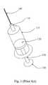
- FIG. 1is a perspective view of a prior art syringe used to inject drugs into the eye.
- the syringeincludes a needle 105 , a luer hub 110 , a chamber 115 , a plunger 120 , a plunger shaft 125 , and a thumb rest 130 .
- the drug to be injectedis located in chamber 115 . Pushing on the thumb rest 130 causes the plunger 120 to expel the drug through needle 105 .
- the surgeonis required to puncture the eye tissue with the needle, hold the syringe steady, and actuate the syringe plunger (with or without the help of a nurse) to inject the fluid into the eye.
- the volume injectedis typically not controlled in an accurate manner because the vernier on the syringe is not precise relative to the small injection volume. Fluid flow rates are uncontrolled. Reading the vernier is also subject to parallax error. Tissue damage may occur due to an “unsteady” injection.
- a commercially available fluid dispenseris the ULTRATM positive displacement dispenser available from EFD Inc. of Buffalo, R.I.
- the ULTRA dispenseris typically used in the dispensing of small volumes of industrial adhesives. It utilizes a conventional syringe and a custom dispensing tip. The syringe plunger is actuated using an electrical stepper motor and an actuating fluid. With this type of dispenser, the volumes delivered are highly dependent on fluid viscosity, surface tension, and the specific dispensing tip.
- Parker Hannifin Corporation of Cleveland, Ohiodistributes a small volume liquid dispenser for drug discovery applications made by Aurora Instruments LLC of San Diego, Calif.
- the Parker/Aurora dispenserutilizes a piezo-electric dispensing mechanism. While precise, this dispenser is expensive and requires an electrical signal to be delivered to the dispensing mechanism.
- U.S. Pat. No. 6,290,690discloses an ophthalmic system for injecting a viscous fluid (e.g. silicone oil) into the eye while simultaneously aspirating a second viscous fluid (e.g. perflourocarbon liquid) from the eye in a fluid/fluid exchange during surgery to repair a retinal detachment or tear.
- the systemincludes a conventional syringe with a plunger.
- One end of the syringeis fluidly coupled to a source of pneumatic pressure that provides a constant pneumatic pressure to actuate the plunger.
- the other end of the syringeis fluidly coupled to an infusion cannula via tubing to deliver the viscous fluid to be injected.
- a dosage control device for an ophthalmic injection systemthat assures that the correct dosage is delivered during each injection. Such a device would eliminate dosing error on the part of medical professionals during an injection and would be desirable for insuring accurate dosing during a clinical trial of a drug.
- the present inventionis an injection device with a dispensing chamber, a plunger, a controller, a memory device resistant to sterilization, and a housing at least partially enclosing the dispensing chamber and the plunger.
- the dispensing chamberhas an inner surface and an outer surface. The inner surface defines a cavity for receiving a quantity of a substance.
- the plungeris engaged with the inner surface of the dispensing chamber, is capable of sliding in the cavity of the dispensing chamber, and is fluidly sealed to the inner surface of the dispensing chamber.
- the controllercontrols the operation of the injection device.
- the controllerreads dosage data from the memory device and operates the injection device to deliver a dosage corresponding to the dosage data.
- the present inventionis an ophthalmic injection system having a tip segment and limited reuse assembly.
- the tip segmentincludes a dispensing chamber, a plunger, a memory device resistant to sterilization, and a housing at least partially enclosing the dispensing chamber and the plunger.
- the dispensing chamberhas an inner surface and an outer surface. The inner surface defines a cavity for receiving a quantity of a substance.
- the plungeris engaged with the inner surface of the dispensing chamber, is capable of sliding in the cavity of the dispensing chamber, and is fluidly sealed to the inner surface of the dispensing chamber.
- the plungerhas a proximate end with a first mechanical linkage interface. The controller controls the operation of the injection device.
- the limited reuse assemblyincludes a power source, a controller for controlling the operation of the system, a actuator with a shaft, a second mechanical linkage interface located on an end of the shaft, and a housing at least partially enclosing the controller and the actuator.
- the controllerreads dosage data from the memory device and operates the injection device to deliver a dosage corresponding to the dosage data.
- FIG. 1is a perspective view of a prior art syringe.
- FIG. 2is a view of an ophthalmic hand piece including a drug delivery tip segment and a limited reuse assembly according to an embodiment of the present invention.
- FIG. 3is a diagram of a memory device circuit for use in a drug delivery tip segment according to an embodiment of the present invention.
- FIG. 4is an exploded cross section view of a drug delivery tip segment for an ophthalmic hand piece according to an embodiment of the present invention.
- FIG. 5is cross section view of a drug delivery tip segment and a limited reuse assembly according to an embodiment of the present invention.
- FIG. 6is a perspective view of a dosage control card according to an embodiment of the present invention.
- FIG. 7is a perspective view of a console, a drug delivery device, and a dosage control card according to an embodiment of the present invention.
- FIG. 8is a circuit diagram of a hard-wired memory circuit according to an embodiment of the present invention.
- FIG. 2depicts one view of an ophthalmic hand piece including a drug delivery tip segment and a limited reuse assembly according to an embodiment of the present invention.
- the hand pieceincludes a tip segment 205 and a limited reuse assembly 250 .
- the tip segment 205includes a needle 210 , a housing 215 , a plunger connection 225 , and an optional light 275 .
- the limited reuse assembly 250includes a housing 255 , a switch 270 , a lock mechanism 265 , and a threaded portion 260 .
- Tip segment 205is capable of being connected to and removed from Limited reuse assembly 250 .
- tip segment 205has a threaded portion on an interior surface of housing 215 that screws onto the threaded portion 260 of limited reuse assembly 250 .
- lock mechanism 265secures tip segment 215 to limited reuse assembly 250 .
- Lock mechanism 265may be in the form of a button, a sliding switch, or a cantilevered mechanism.
- Other mechanisms for connecting tip segment 205 to limited reuse assembly 250such as those involving structural features that mate with each other, are commonly known in the art and are within the scope of the present invention.
- Needle 210is adapted to deliver a substance, such as a drug, into an eye. Needle 210 may be of any commonly known configuration. Preferably, needle 210 is designed such that its thermal characteristics are conducive to the particular drug delivery application. For example, when a heated drug is to be delivered, needle 210 may be relatively short (several millimeters) in length to facilitate proper delivery of the drug.
- Switch 270is adapted to provide an input to the system.
- switch 270may be used to activate the system or to turn on a heater.
- Other switches, buttons, or user-directed control inputsare commonly known and may be employed with limited reuse assembly 250 and/or tip segment 205 .
- Optional light 275is illuminated when tip segment 205 is ready to be used.
- Optional light 275may protrude from housing 215 , or it may be contained within housing 215 , in which case, optional light 275 may be seen through a clear portion of housing 215 .
- optional light 275may be replaced by an indicator, such as a liquid crystal display, segmented display, or other device that indicates a status or condition of the tip segment.
- optional light 275may also pulse on and off to indicate other states such as but not limited to a system error, fully charged battery, insufficiently charged battery or faulty connection between the tip segment 205 and limited use assembly 250 .
- FIG. 3is a diagram of a memory device circuit for use in a drug delivery tip segment according to an embodiment of the present invention.
- the circuitincludes optional light 275 , fuse 375 , controller 305 , power source 310 , and memory device 315 .
- Controller 305controls the operation of power source 310 and reads data stored on memory device 315 .
- optional light 275is a light emitting diode of any appropriate color.
- optional light 275may be a lamp, a phosphorescent light, or any other similar electric or electronic light source.
- optional light 275is any type of indicator, such as a liquid crystal display or a segmented display.
- Fuse 375is a fuse with a current rating greater than the operating current of optional light 275 .
- Fuse 375may be a common glass encapsulated fuse, a trace fuse on a printed circuit board, or other similar structure that provides the function of a fuse.
- a switch or switching circuitmay be used to provide the functionality of fuse 375 .
- Power source 310is typically a rechargeable battery with associated electronics. In other cases, power source 310 is a disposable battery or simply a connection to an independent power source, such as a switch mode power supply. In this embodiment, power source 310 also includes the charging and current driving electronics associated with it.
- Controller 305is typically an integrated circuit with power, input, and output pins capable of performing logic functions.
- controller 305is a targeted device controller.
- controller 305performs specific control functions targeted to a specific device or component, such as a heater or a power supply.
- a heater controllerhas the basic functionality to control a heater.
- controller 305is a microprocessor.
- controller 305is programmable so that it can function to control more than one component of the device.
- controller 305is not a programmable microprocessor, but instead is a special purpose controller configured to control different components that perform different functions.
- controller 305controls power supply 310 and reads data from memory device 315 . While depicted as one component in FIG. 1 , controller 305 may be made of many different components or integrated circuits.
- Memory device 315is a hard wired memory device such as that described in FIG. 8 . Unlike a typical semiconductor memory, such as an EEPROM or flash memory, which cannot withstand gamma sterilization without data loss, memory device 315 withstands gamma sterilization without data loss. Memory device 315 is typically packaged with a disposable tip segment or drug delivery device. Such a package is sterilized before leaving the factory. In order to preserve the data stored on memory device 315 , memory device 315 is hard-wired or resistant to commonly used sterilization techniques, such as gamma sterilization.
- FIG. 4is an exploded cross section view of a drug delivery tip segment for an ophthalmic hand piece according to an embodiment of the present invention.
- the drug delivery tip segmentincludes housing 215 , needle 210 , optional light 275 , fuse 375 , memory device 315 , plunger shaft 410 , plunger tip (or fluid seal) 415 , mechanical linkage interface 420 , dispensing chamber 405 , dispensing chamber housing 425 , heater 450 , thermal sensor 460 , and optional luer 430 .
- mechanical linkage interfaceis located on one end of plunger shaft 410 .
- Plunger tip 415is located on the other end of plunger shaft 410 .
- Plunger shaft 410 and plunger tip 415collectively form a plunger.
- Dispensing chamber 405is enclosed by dispensing chamber housing 425 and plunger tip 415 .
- Plunger tip 415forms a fluid seal with the interior surface of dispensing chamber housing 425 .
- Needle 210is fluidly coupled to dispensing chamber 405 . In this manner, a substance located in dispensing chamber 405 can be contacted by plunger tip 415 and pushed out of needle 210 .
- Needle 210may be secured to the drug delivery tip segment by an optional luer 430 or may be permanently attached.
- Heater 450is located on dispensing chamber housing 425 and at least partially surrounds dispensing chamber 405 .
- Housing 215forms an outer skin on the drug delivery tip segment and at least partially encloses plunger shaft 410 , plunger tip 415 , dispensing chamber 405 , and dispensing chamber housing 425 .
- a substance to be delivered into an eyeis located in dispensing chamber 405 .
- the substanceis contacted by the inner surface of dispensing chamber housing 425 and one face of plunger tip 415 .
- dispensing chamber 405is cylindrical in shape.
- Heater 450is in thermal contact with dispensing chamber housing 425 . In this manner, heater 450 is adapted to heat the contents of dispensing chamber 425 .
- Currentis applied to heater 450 through an electrical interface (not shown).
- Thermal sensor 460provides temperature information to assist in controlling the operation of heater 450 .
- the substance located in dispensing chamber 405is a drug that is preloaded into the dispensing chamber.
- the drug delivery tip segmentis appropriate as a single use consumable product.
- Such a disposable productcan be assembled at a factory with a dosage of a drug installed. A precise volume of a substance can be preloaded into the delivery device.
- a set quantity of the drugcan be preloaded. For example, 100 microliters of a drug can be loaded into dispensing chamber 405 , and any quantity up to 100 microliters can be dispensed.
- the plunger(plunger shaft 410 and plunger tip 415 ) can be moved a precise distance to deliver a precise dosage of drug from the dispensing chamber 405 , through the needle 210 , and into an eye. This provides for flexibility of dosing and for ease of assembly.
- different dosagesmay be preloaded into different tip segments. For example, dosages up to ten microliters in one microliter increments may be preloaded into dispensing chamber 405 of different tip segments. The proper dosage may be selected by selecting the tip segment with the proper amount of drug preloaded in dispensing chamber 405 .
- the drug delivery tip segment of FIG. 4is attached to a limited reuse assembly (not shown).
- the limited reuse assemblyprovides power to the tip segment and illuminates optional light 275 .
- a currentpasses through optional light 275 and fuse 375 .
- Mechanical linkage interface 420mates with a mechanical interface on the limited reuse assembly.
- Dosage informationis read from memory device 315 . This dosage information enables the controller to operate the plunger such that the correct dosage is delivered.
- plunger tip 415is displaced.
- the displacement of plunger tip 415in turn displaces the substance contained in dispensing chamber 405 .
- the substanceis pushed out of needle 210 .
- the controller(not shown) directs an increased current to be sent through fuse 375 .
- This increased currentburns out fuse 375 indicating that the tip segment has been used and is to be discarded. Since the tip segment of the depicted embodiment is a single use tip segment, once fuse 375 is blown, the tip segment is no longer operable. In addition, once fuse 375 is blown, data cannot be read from memory device 315 .
- FIG. 5is a cross section view of a drug delivery tip segment and a limited reuse assembly according to an embodiment of the present invention.
- FIG. 5shows how tip segment 205 interfaces with limited reuse assembly 250 .
- tip segment 205includes memory assembly 555 , mechanical linkage interface 420 , plunger 505 , dispensing chamber housing 425 , tip segment housing 215 , heater 450 , thermal sensor 460 , needle 210 , dispensing chamber 405 , interface 530 , and tip interface connector 520 .
- Limited reuse assembly 250includes mechanical linkage 545 , actuator shaft 510 , actuator 515 , power source 310 , controller 305 , limited reuse assembly housing 255 , interface 535 , and limited reuse assembly interface connector 525 .
- mechanical linkage 420is located on one end of plunger 505 .
- the other end of plunger 505forms one end of dispensing chamber 405 .
- Plunger 505is adapted to slide within dispensing chamber 405 .
- An outer surface of plunger 505is fluidly sealed to the inner surface of dispensing chamber housing 425 .
- Dispensing chamber housing 425surrounds the dispensing chamber 405 .
- dispensing chamber housing 425has a cylindrical shape.
- dispensing chamber 405also has a cylindrical shape.
- Needle 210is fluidly coupled to dispensing chamber 405 .
- a substance contained in dispensing chamber 405can pass through needle 210 and into an eye.
- Heater 450at least partially surrounds dispensing chamber housing 425 .
- heater 450is adapted to heat dispensing chamber housing 425 and any substance contained in dispensing chamber 405 .
- heater 450is in thermal contact with dispensing chamber housing 425 .
- Interface 530connects heater 450 with tip interface connector 520 .
- tip segment housing 215The components of tip segment 205 , including dispensing chamber housing 425 , heater 450 , and plunger 505 are at least partially enclosed by tip segment housing 215 .
- a sealis present on a bottom surface of tip segment housing 215 .
- plunger 505is sealed to tip segment housing 215 .
- This sealprevents contamination of any substance contained in dispensing chamber 405 .
- a sealis desirable.
- This sealcan be located at any point on plunger 505 or on dispensing chamber housing 425 .
- tip segment housing 215maybe connected to dispensing chamber housing 425 to form an air tight or fluid tight seal.
- tip segment housing 215maybe sealed to plunger 505 near the end on which mechanical linkage interface 420 resides. In such a case, an air tight or fluid tight seal may be formed between a location on plunger 505 and tip segment housing 215 .
- tip segment 205may contain a plunger stop mechanism.
- the bottom portion of plunger 505(the portion on which mechanical linkage interface 420 resides) is adapted to contact the bottom portion of dispensing chamber housing 425 .
- mechanical linkage interface 420also advances upward toward needle 210 .
- a top surface of mechanical linkage interface 420contacts a bottom surface of dispensing chamber housing 425 .
- the protrusions on the bottom end on plunger 505 and the bottom surface of dispensing chamber housing 425form a plunger stop mechanism.
- Such a plunger stop mechanismcan provide a safety feature, such as to prevent plunger 505 from contacting needle 210 and possibly dislodging it.
- a plunger stop mechanismmay also include a locking mechanism so that plunger 505 cannot be retracted or moved away from needle 210 when needle 210 is removed from the eye.
- Such a plunger lock mechanismhelps to prevent reflux of the substance when needle 210 is removed.
- power source 310provides power to actuator 515 .
- An interface (not shown) via the controller 305connects the power source 310 to the actuator 515 .
- Actuator 515is connected to actuator shaft 510 .
- actuator shaft 510is integral with actuator 515 .
- Mechanical linkage interface 545is connected to actuator shaft 510 . In this configuration, as actuator 515 moves actuator shaft 510 upward toward needle 210 mechanical linkage 545 also moves upward toward needle 210 .
- Controller 305is connected via interface 535 to limited reuse assembly interface connecter 525 .
- Limited reuse assembly interface connecter 525is located on a top surface of limited reuse assembly housing 255 adjacent to mechanical linkage interface 545 . In this manner, both limited reuse assembly interface connector 525 and mechanical linkage interface 545 are adapted to be connected with tip interface connector 520 and mechanical linkage interface 420 respectively.
- Controller 305 and actuator 515are connected by an interface (not shown). This interface (not shown) allows controller 305 to control the operation of actuator 515 .
- the controller 305has the ability to interface with either a rechargeable or non rechargeable power source 310 .
- Controller 305may control the current or voltage provided to memory assembly 555 , for example, to illuminate an optional light 275 and blow a fuse 375 contained within memory assembly 555 .
- Tip segment 205is adapted to mate with or attach to limited reuse assembly 250 as previously described.
- mechanical linkage interface 420 located on a bottom surface of plunger 505is adapted to connect with mechanical linkage interface 545 located near a top surface of limited reuse assembly housing 255 .
- tip interface connector 520is adapted to connect with limited reuse assembly interface connector 525 .
- actuator 515 and actuator shaft 510are adapted to drive plunger 505 upward toward needle 210 .
- an interfaceis formed between controller 305 and heater 450 . A signal can pass from controller 305 to heater 450 through interface 535 , limited reuse assembly interface connector 525 , tip interface connector 520 , and heater interface 530 .
- controller 305controls the operation of actuator 515 .
- Actuator 515is actuated and actuator shaft 510 is moved upward toward needle 210 .
- mechanical linkage interface 545which is connected to mechanical linkage interface 420 , moves plunger 505 upward toward needle 210 .
- a substance located in dispensing chamber 405is then expelled through needle 210 .
- controller 305controls the operation of heater 450 .
- Heater 450is adapted to heat an outside surface of dispensing chamber housing 425 . Since dispensing chamber housing 425 is at least partially thermally conductive, heating dispensing chamber housing 425 heats a substance located in dispensing chamber 405 . Temperature information can be transferred from thermal sensor 460 through interface 530 , tip interface connector 520 , limited reuse assembly interface connector 525 , and interface 535 back to controller 305 . This temperature information can be used to control the operation of heater 450 . Typically, controller 305 controls the amount of current that is sent to heater 450 . The more current sent to heater 450 , the hotter it gets.
- controller 305can use a feed back loop utilizing information from thermal sensor 460 to control the operation of heater 450 .
- Any suitable type of control algorithmsuch as a proportional integral derivative (PID) algorithm, can be used to control the operation of heater 450 .
- PIDproportional integral derivative
- Memory assembly 555is connected to interface 530 in tip segment 205 .
- memory assembly 555includes optional light 275 , fuse 375 , and memory device 315 as described with respect to FIGS. 3 and 4 .
- the memory device 315 in memory assembly 555is typically a hard wired memory circuit like that depicted in FIG. 8 .
- the memory device 315 in memory assembly 555is configured to store dosage information for a drug contained in dispensing chamber 405 .
- Controller 305is also adapted to interface with memory assembly 555 . In this manner, controller 305 directs current to flow from power source 310 to memory assembly 555 . Controller 305 also reads data from the memory device contained in memory assembly 555 . A current passing through optional light 275 and fuse 375 illuminates optional light 275 . After the tip segment 205 has been used (after the substance has been dispensed), controller 305 directs power source 310 to deliver an increased current to blow fuse 375 and extinguish optional light 275 . This indicates that the tip segment 205 has been used and that it should be discarded. In addition, controller 305 may check fuse 375 to see if it is blown. If it is blown, controller 305 defines tip segment 205 as rendered inoperable.
- fuse 375may be placed such that when it is blown, no power is delivered to the tip segment. In such a case, once fuse 375 is blown, optional light 275 is extinguished and the tip segment is rendered inoperable. In addition, once fuse 375 is blown, data may no longer be read from the memory device in memory assembly 555 .
- interface 530 , tip interface connector 520 , limited reuse assembly interface 525 , and interface 535all form a data interface between tip segment 205 and limited reuse assembly 250 .
- information from the thermal sensor 460maybe passed back to limited reuse assembly 250 via this series of interfaces and interface connectors.
- data stored on the memory device in memory assembly 555may also be read by controller 305 via this series of interfaces and interface connectors.
- mechanical linkage interface 545is connected to mechanical linkage interface 420 and tip interface connector 520 is connected to limited reuse assembly interface connector 525 .
- the connection of tip interface connector 520 to limited reuse assembly interface connector 525allows the transfer of information or data from thermal sensor 460 and the memory device in memory assembly 555 to controller 305 .
- the memory device in memory assembly 555stores dosage information.
- Information about a proper drug dosage for a drug contained in dispensing chamber 405is stored in the memory device in memory assembly 555 .
- controller 305can read the dosage information from the memory device in memory assembly 555 and operate actuator 515 in a manner suitable to deliver the proper dosage. For example, 100 microliters may be contained dispensing chamber 405 .
- Information stating that a dosage of 20 microliters is to be delivered into an eyemaybe stored on the memory device in memory assembly 555 . In such a case, controller 305 reads the dosage information (that 20 microliters should be delivered into the eye) from the memory device in memory assembly 555 .
- Controller 305can then operate actuator 515 to deliver the 20 microliter dosage. Controller 305 can cause actuator 515 to move actuator shaft 510 and mechanical linkage 545 a set distance related to a dosage of 20 microliters. In such a case, plunger 505 is moved this set distance so that only 20 micro liters of a drug is expelled from needle 210 and into an eye.
- controller 305has various plunger distances stored on it. Each of these plunger distances is related to a different dosage. For example, one plunger distance may be associated with a dosage of 20 microliters and a second larger plunger distance may be associated with a dosage of 40 microliters. In this manner controller 305 can use the set plunger distance to control actuator 515 , actuator shaft 510 , mechanical linkage interface 545 , and mechanical linkage interface 420 to move plunger 505 this set distance. In other words, controller 305 reads dosage information from the memory device in memory assembly 555 , finds the plunger distance associated with that dosage, and uses the distance that plunger 505 must travel to deliver a given dosage of drug.
- actuator shaft 510 and mechanical linkage interface 545are connected to mechanical linkage interface 420 , a movement of actuator shaft 510 produces a corresponding movement of plunger 505 .
- controller 305controls the movement of actuator 515 such that plunger 505 is moved the proper distance to deliver the required dosage from dispensing chamber 405 , through needle 210 , and into an eye.
- controller 305may calculate a distance that plunger 505 must be moved to deliver the desired dosage. For example, if dosage information corresponding to a drug dosage of 20 microliters is read from the memory device in memory assembly 555 by controller 305 , then controller 305 may use this information to calculate a proper distance that plunger 505 must be moved. Since the volume of dispensing chamber 405 as well as the volume of a drug loaded in dispensing chamber 405 is known, a distance that plunger 505 must be moved to deliver that required dosage can be calculated by controller 305 .
- the volume of the dispensing chambercan be calculated by using the cross section area of the cylinder (the area of a circle) times the height of the dispensing chamber. This simple mathematical formula can be used to calculate the total volume of the dispensing chamber 405 . Since the cross section area of dispensing chamber 405 is constant for any given application, the height which corresponds to a distance that plunger 505 travels can be calculated for any dosage amount.
- dispensing chamber 405For example, assume that 100 microliters of a drug is loaded into dispensing chamber 405 and that the cross section area of dispensing chamber 405 is 10. When dispensing chamber 405 is in the shape of a cylinder, the height of that cylinder is also 10. To deliver a dosage of 20 microliters which corresponds to 20% of the total volume of dispensing chamber 405 , it is necessary to move plunger 505 upward toward needle 210 a distance of 2. In other words, a dosage of 20 microliters corresponds to 20% of the total volume of dispensing chamber 405 . In such a case, plunger 505 should be moved upward toward needle 210 a distance equal to 20% of the total height of dispensing chamber 405 . Controller 305 can then control actuator 515 such that actuator shaft 510 moves drives plunger 505 upward a distance of 20% of the total height of dispensing chamber 405 .
- controller 305may read information about a rate at which plunger 505 should be moved in order to properly deliver a dosage of drug. In such a case, controller 305 reads information about the rate of drug delivery from memory assembly 555 and uses that information to operate actuator 515 to drive plunger 505 at that rate.
- the rate at which plunger 505 movesmay be fixed or variable. In some applications, it may be desirable to move plunger 505 faster than in other applications. For example, when the drug contained in dispensing 405 is a drug that should be heated before being injected into an eye, it maybe desirable to drive plunger 505 at a rate such that the heated drug does not cool and clog needle 210 . In other applications, it may be desirable to move plunger 505 slowly in order to improve the delivery of a drug contained in dispensing chamber 405 .
- a number of different drug delivery tip segments 205maybe manufactured and loaded with a drug at the factory. Dosage information can also be loaded onto the memory device in memory assembly 555 at the factory. A number of different tip segments, each with the same amount of drug contained in the dispensing chamber 405 but with different dosage information stored on the memory device in memory assembly 555 , can be manufactured and shipped. Alternatively, a number of different tip segments, each with a different amount of drug contained in the dispensing chamber 405 with corresponding dosage information stored on the memory device in memory assembly 555 , can be manufactured and shipped.
- a doctorcan then order the tip segment 205 with the required dosage information on the memory device in memory assembly 555 .
- Packagingcan be clearly labeled to identify the dosage information so that the proper dosage is administered to a patient.
- memory assembly 555is located on a separate card 600 , that card 600 can be included with the drug delivery device 405 .
- FIG. 6is a perspective view of a dosage control card according to an embodiment of the present invention.
- dosage control device 600is implemented in a memory card-type device. The same structure and functionality previously described with respect to memory assembly 555 of FIG. 5 is implemented in dosage control device 600 .
- Dosage control device 600contains a fuse, light, and memory device (not shown) as previously described.
- Dosage control device 600has a connector end 605 , a body 610 , and a lighted end 615 .
- the connector end 605is adapted to connect to and allow communication with a console box 700 .
- a light 275is incorporated in lighted end 615 .
- FIG. 7is a perspective view of a console, a drug delivery device, and a dosage control card according to an embodiment of the present invention.
- console box 700includes a slot 715 , a port 720 , a button 725 , and indicators 730 .
- Slot 715is adapted to receive the connector end 605 of dosage control card 600 .
- An injection device 705has a connector 710 .
- Port 720is adapted to receive connector 710 .
- Console box 700includes a controller (not shown) that controls the operation of injection device 705 .
- Injection device 705includes the components of the embodiment shown in FIG. 5 with the exception of the power source, the controller, and possibly several indicators or lights. Those components are contained in the console box 700 .
- the heateris optional, as it is optional in the previously described devices.
- a medical professionalremoves injection device 705 and dosage control device 600 from sterilized packaging (not shown).
- the injection device 705is connected to the console box 700 by connecting connector 710 to port 720 .
- Dosage control device 600is inserted into slot 715 .
- the controller (not shown) in console box 700reads the dosage information from the memory device on dosage control device 600 .
- the controller in console box 700then operates the injection device 705 to deliver the appropriate dosage in the manner previously described.
- FIG. 8is a circuit diagram of a hard wired memory circuit according to an embodiment of the present invention.
- seven fusesF 1 , F 2 , F 3 , F 4 , F 5 , F 6 , and F 7
- six resistorsR 1 , R 2 , R 3 , R 4 , R 5 , and R 6
- one LEDL 7
- the embodiment of FIG. 8also includes six terminals (T 1 , T 2 , T 3 , T 4 , T 5 , and T 6 ), a voltage line 810 , and a ground line 820 .
- Fuse F 7 and LED L 7correspond to fuse 375 and optional light 275 in FIGS. 3 and 4 .
- the embodiment of FIG. 8is capable of storing a five bit number and a checksum.
- a voltage applied to voltage line 810can be read across each of the six resistors. If the fuse in series with a particular resistor is blown, then no voltage will be read across that resistor. These two states (the presence or absence of a voltage across a resistor) correspond to a one or a zero in a binary number.
- five of the resistorscontain dosage data. This dosage data is one of 32 distinct numbers.
- the sixth resistorholds checksum information.
- the five bitscorrespond to the first five resistors (R 1 -R 5 ), and the checksum corresponds to the sixth resistor (R 6 ).
- the voltage across each resistoris read between the respective terminal (T 1 -T 6 ) and the ground line 820 .
- the five bit binary numberis 10011 or 19, and the checksum is 1.
- the controllerreads this number and the checksum, determines if the number is correct in light of the checksum, and then determines a dosage based on the number.
- the dosage control devicedefines 32 different dosage levels.
- the number 19could correspond to a dosage of 48 microliters. In such a case, dosages from 10 to 72 microliters in two microliter increments can be defined by the dosage control device.
- the controllercan then operate the plunger to deliver 48 microliters. After the dosage is delivered, a fuse can be blown, and the card can be rendered inoperable, as previously described.
- the present inventionprovides an improved system for delivering precise volumes of a substance into an eye.
- the present inventionprovides a drug delivery device that is capable of delivering a precise dosage.
- the tip segmentinterfaces with a universal hand piece limited reuse assembly.
- Information on the dosage control devicedirects the injection device to deliver the proper dosage.
Landscapes
- Health & Medical Sciences (AREA)
- General Health & Medical Sciences (AREA)
- Public Health (AREA)
- Biomedical Technology (AREA)
- Heart & Thoracic Surgery (AREA)
- Animal Behavior & Ethology (AREA)
- Life Sciences & Earth Sciences (AREA)
- Engineering & Computer Science (AREA)
- Veterinary Medicine (AREA)
- Vascular Medicine (AREA)
- Anesthesiology (AREA)
- Hematology (AREA)
- Ophthalmology & Optometry (AREA)
- Nuclear Medicine, Radiotherapy & Molecular Imaging (AREA)
- Surgery (AREA)
- Infusion, Injection, And Reservoir Apparatuses (AREA)
- Prostheses (AREA)
Abstract
Description
Claims (19)
Priority Applications (23)
| Application Number | Priority Date | Filing Date | Title |
|---|---|---|---|
| US11/688,573US7811252B2 (en) | 2006-05-17 | 2007-03-20 | Dosage control device |
| CA002664635ACA2664635A1 (en) | 2006-10-16 | 2007-10-04 | Dosage control device |
| EP07873980AEP2077809A2 (en) | 2006-10-16 | 2007-10-04 | Dosage control device |
| JP2009533434AJP5155326B2 (en) | 2006-10-16 | 2007-10-04 | Batch control device |
| PCT/US2007/080376WO2008112011A2 (en) | 2006-10-16 | 2007-10-04 | Dosage control device |
| AU2007348948AAU2007348948A1 (en) | 2006-10-16 | 2007-10-04 | Dosage control device |
| BRPI0717450-0A2ABRPI0717450A2 (en) | 2006-10-16 | 2007-10-09 | Ophthalmic Injection Device Including Dosage Control Device |
| US12/444,044US9022970B2 (en) | 2006-10-16 | 2007-10-09 | Ophthalmic injection device including dosage control device |
| AU2007349204AAU2007349204B2 (en) | 2006-10-16 | 2007-10-09 | Ophthalmic injection device including dosage control device |
| KR1020097010161AKR20090080983A (en) | 2006-10-16 | 2007-10-09 | Ophthalmic infusion device with dosing control device |
| MX2009003717AMX2009003717A (en) | 2006-10-16 | 2007-10-09 | Ophthalmic injection device including dosage control device. |
| EP07874450.5AEP2077810B1 (en) | 2006-10-16 | 2007-10-09 | Ophthalmic injection device including dosage control device |
| ES07874450.5TES2552716T3 (en) | 2006-10-16 | 2007-10-09 | Ophthalmic injection device that includes a dose control device |
| CN2007800383990ACN101534759B (en) | 2006-10-16 | 2007-10-09 | Ophthalmic injection device including dosage control device |
| JP2009533445AJP2010506681A (en) | 2006-10-16 | 2007-10-09 | Ophthalmic injection device including a medication control device |
| CA2920921ACA2920921C (en) | 2006-10-16 | 2007-10-09 | Ophthalmic injection device including dosage control device |
| RU2009118457/14ARU2009118457A (en) | 2006-10-16 | 2007-10-09 | EYE INJECTION DEVICE CONTAINING DOSAGE CONTROL DEVICE |
| CA2666948ACA2666948C (en) | 2006-10-16 | 2007-10-09 | Ophthalmic injection device including dosage control device |
| PCT/US2007/080756WO2008115270A2 (en) | 2006-10-16 | 2007-10-09 | Ophthalmic injection device including dosage control device |
| ARP070104556AAR063296A1 (en) | 2006-10-16 | 2007-10-12 | DOSE CONTROL DEVICE |
| ARP070104545AAR063285A1 (en) | 2006-10-16 | 2007-10-12 | DOSAGE CONTROL DEVICE |
| TW096138467ATW200833382A (en) | 2006-10-16 | 2007-10-15 | Ophthalmic injection device including dosage control device |
| TW096138460ATW200826987A (en) | 2006-10-16 | 2007-10-15 | Dosage control device |
Applications Claiming Priority (3)
| Application Number | Priority Date | Filing Date | Title |
|---|---|---|---|
| US11/435,906US20070270750A1 (en) | 2006-05-17 | 2006-05-17 | Drug delivery device |
| US92149706P | 2006-10-16 | 2006-10-16 | |
| US11/688,573US7811252B2 (en) | 2006-05-17 | 2007-03-20 | Dosage control device |
Related Parent Applications (2)
| Application Number | Title | Priority Date | Filing Date |
|---|---|---|---|
| US11/435,906Continuation-In-PartUS20070270750A1 (en) | 2006-05-17 | 2006-05-17 | Drug delivery device |
| US92149706PContinuation-In-Part | 2006-05-17 | 2006-10-16 |
Related Child Applications (1)
| Application Number | Title | Priority Date | Filing Date |
|---|---|---|---|
| US12/444,044Continuation-In-PartUS9022970B2 (en) | 2006-10-16 | 2007-10-09 | Ophthalmic injection device including dosage control device |
Publications (2)
| Publication Number | Publication Date |
|---|---|
| US20070270760A1 US20070270760A1 (en) | 2007-11-22 |
| US7811252B2true US7811252B2 (en) | 2010-10-12 |
Family
ID=39721776
Family Applications (2)
| Application Number | Title | Priority Date | Filing Date |
|---|---|---|---|
| US11/688,573ActiveUS7811252B2 (en) | 2006-05-17 | 2007-03-20 | Dosage control device |
| US12/443,898Expired - Fee RelatedUS8118790B2 (en) | 2006-05-17 | 2007-10-09 | Battery operated surgical hand piece with disposable end |
Family Applications After (1)
| Application Number | Title | Priority Date | Filing Date |
|---|---|---|---|
| US12/443,898Expired - Fee RelatedUS8118790B2 (en) | 2006-05-17 | 2007-10-09 | Battery operated surgical hand piece with disposable end |
Country Status (14)
| Country | Link |
|---|---|
| US (2) | US7811252B2 (en) |
| EP (2) | EP2077809A2 (en) |
| JP (2) | JP5155326B2 (en) |
| KR (1) | KR20090091133A (en) |
| CN (3) | CN101534758A (en) |
| AR (9) | AR063297A1 (en) |
| AU (2) | AU2007348948A1 (en) |
| BR (1) | BRPI0717303B8 (en) |
| CA (2) | CA2664635A1 (en) |
| ES (1) | ES2614646T3 (en) |
| MX (1) | MX2009003395A (en) |
| RU (1) | RU2009118434A (en) |
| TW (2) | TW200826986A (en) |
| WO (2) | WO2008112011A2 (en) |
Cited By (13)
| Publication number | Priority date | Publication date | Assignee | Title |
|---|---|---|---|---|
| US8864703B2 (en) | 2010-10-05 | 2014-10-21 | Alcon Research, Ltd. | Drug introduction and placement system |
| US9763827B2 (en) | 2013-04-30 | 2017-09-19 | Tear Film Innovations, Inc. | Systems and methods for the treatment of eye conditions |
| US10092449B2 (en) | 2013-04-30 | 2018-10-09 | Tear Film Innovations, Inc. | Systems and methods for the treatment of eye conditions |
| US10206813B2 (en) | 2009-05-18 | 2019-02-19 | Dose Medical Corporation | Implants with controlled drug delivery features and methods of using same |
| US10245178B1 (en) | 2011-06-07 | 2019-04-02 | Glaukos Corporation | Anterior chamber drug-eluting ocular implant |
| US10406029B2 (en) | 2001-04-07 | 2019-09-10 | Glaukos Corporation | Ocular system with anchoring implant and therapeutic agent |
| US10959941B2 (en) | 2014-05-29 | 2021-03-30 | Glaukos Corporation | Implants with controlled drug delivery features and methods of using same |
| US10974063B2 (en) | 2016-06-30 | 2021-04-13 | Alcon Inc. | Light therapy for eyelash growth |
| US11318043B2 (en) | 2016-04-20 | 2022-05-03 | Dose Medical Corporation | Bioresorbable ocular drug delivery device |
| US11564833B2 (en) | 2015-09-25 | 2023-01-31 | Glaukos Corporation | Punctal implants with controlled drug delivery features and methods of using same |
| US11925578B2 (en) | 2015-09-02 | 2024-03-12 | Glaukos Corporation | Drug delivery implants with bi-directional delivery capacity |
| US12201555B2 (en) | 2009-05-18 | 2025-01-21 | Dose Medical Corporation | Drug eluting ocular implant |
| US12419783B2 (en) | 2010-11-24 | 2025-09-23 | Glaukos Corporation | Drug eluting ocular implant |
Families Citing this family (41)
| Publication number | Priority date | Publication date | Assignee | Title |
|---|---|---|---|---|
| DE10224750A1 (en) | 2002-06-04 | 2003-12-24 | Fresenius Medical Care De Gmbh | Device for the treatment of a medical fluid |
| US8197231B2 (en) | 2005-07-13 | 2012-06-12 | Purity Solutions Llc | Diaphragm pump and related methods |
| US7981095B2 (en) | 2005-07-18 | 2011-07-19 | Tearscience, Inc. | Methods for treating meibomian gland dysfunction employing fluid jet |
| US8950405B2 (en)* | 2006-05-15 | 2015-02-10 | Tearscience, Inc. | Treatment of obstructive disorders of the eye or eyelid |
| US20090043365A1 (en) | 2005-07-18 | 2009-02-12 | Kolis Scientific, Inc. | Methods, apparatuses, and systems for reducing intraocular pressure as a means of preventing or treating open-angle glaucoma |
| WO2013003594A2 (en) | 2011-06-28 | 2013-01-03 | Tearscience, Inc. | Methods and systems for treating meibomian gland dysfunction using radio-frequency energy |
| US7981145B2 (en) | 2005-07-18 | 2011-07-19 | Tearscience Inc. | Treatment of meibomian glands |
| US20070060988A1 (en) | 2005-07-18 | 2007-03-15 | Grenon Stephen M | Melting meibomian gland obstructions |
| US20070016256A1 (en) | 2005-07-18 | 2007-01-18 | Korb Donald R | Method and apparatus for treating gland dysfunction |
| US20080114423A1 (en) | 2006-05-15 | 2008-05-15 | Grenon Stephen M | Apparatus for inner eyelid treatment of meibomian gland dysfunction |
| US8128673B2 (en) | 2006-05-15 | 2012-03-06 | Tearscience, Inc. | System for inner eyelid heat and pressure treatment for treating meibomian gland dysfunction |
| US8128674B2 (en) | 2006-05-15 | 2012-03-06 | Tearscience, Inc. | System for outer eyelid heat and pressure treatment for treating meibomian gland dysfunction |
| US8137390B2 (en) | 2006-05-15 | 2012-03-20 | Tearscience, Inc. | System for providing heat treatment and heat loss reduction for treating meibomian gland dysfunction |
| US9314369B2 (en)* | 2006-05-15 | 2016-04-19 | Tearscience, Inc. | System for inner eyelid treatment of meibomian gland dysfunction |
| US20080281292A1 (en)* | 2006-10-16 | 2008-11-13 | Hickingbotham Dyson W | Retractable Injection Port |
| WO2009086112A2 (en)* | 2007-12-20 | 2009-07-09 | University Of Southern California | Apparatus and methods for delivering therapeutic agents |
| US8192401B2 (en) | 2009-03-20 | 2012-06-05 | Fresenius Medical Care Holdings, Inc. | Medical fluid pump systems and related components and methods |
| US8372036B2 (en) | 2009-05-06 | 2013-02-12 | Alcon Research, Ltd. | Multi-layer heat assembly for a drug delivery device |
| US8777897B2 (en)* | 2009-07-06 | 2014-07-15 | Carefusion 303, Inc. | Fluid delivery systems and methods having wireless communication |
| WO2011008858A1 (en) | 2009-07-15 | 2011-01-20 | Fresenius Medical Care Holdings, Inc. | Medical fluid cassettes and related systems and methods |
| US20110112466A1 (en)* | 2009-11-11 | 2011-05-12 | Ramon Carsola Dimalanta | Extended Point Phacoemulsification Tip |
| US8177747B2 (en) | 2009-12-22 | 2012-05-15 | Alcon Research, Ltd. | Method and apparatus for drug delivery |
| US9624915B2 (en) | 2011-03-09 | 2017-04-18 | Fresenius Medical Care Holdings, Inc. | Medical fluid delivery sets and related systems and methods |
| MX341315B (en) | 2011-04-21 | 2016-08-12 | Fresenius Medical Care Holdings Inc | Medical fluid pumping systems and related devices and methods. |
| US9283334B2 (en) | 2011-11-23 | 2016-03-15 | Northgate Technologies Inc. | System for identifying the presence and correctness of a medical device accessory |
| EP2656865A1 (en)* | 2012-04-24 | 2013-10-30 | Sanofi-Aventis Deutschland GmbH | Syringe carrier with needle shield and data storage device for use in a medical auto-injection device |
| US9610392B2 (en) | 2012-06-08 | 2017-04-04 | Fresenius Medical Care Holdings, Inc. | Medical fluid cassettes and related systems and methods |
| US9500188B2 (en)* | 2012-06-11 | 2016-11-22 | Fresenius Medical Care Holdings, Inc. | Medical fluid cassettes and related systems and methods |
| US10842670B2 (en) | 2012-08-22 | 2020-11-24 | Johnson & Johnson Vision Care, Inc. | Apparatuses and methods for diagnosing and/or treating lipid transport deficiency in ocular tear films, and related components and devices |
| USD705924S1 (en)* | 2012-11-02 | 2014-05-27 | Corinthian Ophthalmic, Inc. | Droplet ejection device |
| US9561323B2 (en) | 2013-03-14 | 2017-02-07 | Fresenius Medical Care Holdings, Inc. | Medical fluid cassette leak detection methods and devices |
| JP7051293B2 (en) | 2013-10-24 | 2022-04-11 | アムジエン・インコーポレーテツド | Drug delivery system with temperature sensing control |
| CA2959162C (en)* | 2014-08-28 | 2023-02-28 | Unitract Syringe Pty Ltd | Sensor systems for drug delivery devices |
| CN108366839A (en) | 2015-12-16 | 2018-08-03 | 诺华股份有限公司 | System and method for surgical illuminator that can be manual |
| US10939815B2 (en) | 2016-11-21 | 2021-03-09 | Alcon Inc. | Systems and methods using a vitreous visualization tool |
| US10537401B2 (en) | 2016-11-21 | 2020-01-21 | Novartis Ag | Vitreous visualization system and method |
| CN107512745B (en)* | 2017-08-17 | 2022-04-26 | 厦门百霖净水科技有限公司 | Filter element structure |
| US11801343B2 (en) | 2018-07-12 | 2023-10-31 | Alcon Inc. | Methods and systems for delivering material to a body part |
| CN109730764A (en)* | 2018-12-28 | 2019-05-10 | 颜景臣 | A kind of tumor insertion thermotherapy instrument |
| WO2021051010A1 (en)* | 2019-09-11 | 2021-03-18 | Altaviz, Llc | Micro-volume injectors with dose guidance and methods for use |
| USD1037439S1 (en) | 2022-01-17 | 2024-07-30 | EyePoint Pharamaceuticals, Inc. | Ocular injector |
Citations (39)
| Publication number | Priority date | Publication date | Assignee | Title |
|---|---|---|---|---|
| US1252614A (en)* | 1917-04-24 | 1918-01-08 | Oscar H Pieper | Hot-air syringe. |
| US3892537A (en) | 1973-11-28 | 1975-07-01 | Corning Glass Works | Preload means for ceramic substrate in exhaust gas purifiers |
| US4122850A (en) | 1976-06-07 | 1978-10-31 | Louis Bucalo | Apparatus for providing living beings with absorbable implants |
| GB1551767A (en) | 1975-05-27 | 1979-08-30 | Bucalo L | Implantment of living beings or the like subjects |
| US4265618A (en) | 1977-09-09 | 1981-05-05 | Solar Energy Technology, Inc. | Electrically heated endodontic syringe for injecting thermoplastic material into a root canal cavity |
| US4357136A (en) | 1977-09-09 | 1982-11-02 | Solar Energy Technology, Inc. | Method for filling a root canal |
| WO1982003761A1 (en) | 1981-05-04 | 1982-11-11 | Energy Techn Inc Solar | Syringe for obturation of root canal cavities |
| US4392827A (en) | 1981-11-04 | 1983-07-12 | Howard Martin | Self-contained root canal heated condenser dental instrument |
| US4582488A (en) | 1984-04-27 | 1986-04-15 | Newman Martin H | Dental materials dispenser and applicator |
| WO1987000029A1 (en) | 1985-06-26 | 1987-01-15 | Pitz Richard J | Root canal implant-proximity indicative-delivery means |
| US4684344A (en) | 1986-04-11 | 1987-08-04 | Nalge Company | Electrically powered and heated endodontic syringe |
| US4704088A (en) | 1984-04-27 | 1987-11-03 | Newman Martin H | Dental materials dispenser and applicator |
| EP0348146A1 (en) | 1988-06-21 | 1989-12-27 | Alcon Laboratories, Inc. | Apparatus for injecting viscous fluid into the eye |
| EP0398394A2 (en) | 1983-11-15 | 1990-11-22 | KAMEN, Dean L. | Reservoir assembly for removable engagement with a motor drive |
| US4992045A (en) | 1987-04-01 | 1991-02-12 | Dentsply Research & Development Corp. | Battery powered condenser for root canals |
| US4996477A (en) | 1989-10-26 | 1991-02-26 | A.O. Smith Corporation | Apparatus and method for testing electrically controlled motor |
| EP0419117A2 (en) | 1989-09-19 | 1991-03-27 | Fujitsu Limited | Wafer-scale semiconductor device having fail-safe circuit |
| WO1993002720A1 (en) | 1991-08-06 | 1993-02-18 | Senetek Plc | Medicament injector and method |
| US5383858A (en)* | 1992-08-17 | 1995-01-24 | Medrad, Inc. | Front-loading medical injector and syringe for use therewith |
| WO1996003978A1 (en) | 1994-08-04 | 1996-02-15 | Quadrant Holdings Cambridge Limited | Solid delivery systems for controlled release of molecules incorporated therein and methods of making same |
| WO1999033853A2 (en) | 1997-12-23 | 1999-07-08 | Quadrant Holdings Cambridge Limited | Carbohydrates, useful in solid delivery systems |
| WO1999065548A1 (en) | 1998-06-15 | 1999-12-23 | Medrad, Inc. | Encoding of syringe information |
| WO2001010482A1 (en) | 1999-08-05 | 2001-02-15 | Biocardia, Inc. | A system and method for delivering thermally sensitive and reverse-thermal gelation matrials |
| US6270343B1 (en) | 2000-01-07 | 2001-08-07 | Howard Martin | Endodontic thermal condenser dental instrument |
| US6364865B1 (en) | 1998-11-13 | 2002-04-02 | Elan Pharma International Limited | Drug delivery systems and methods |
| US20020055720A1 (en) | 2000-05-18 | 2002-05-09 | Dentsply Research & Development Corp. | Fluid material dispensing syringe |
| US6436143B1 (en) | 1999-02-22 | 2002-08-20 | Anthony C. Ross | Method and apparatus for treating intervertebral disks |
| US6520930B2 (en)* | 1999-11-24 | 2003-02-18 | Medrad, Inc. | Injectors, injector systems and injector control |
| US20030055380A1 (en) | 2001-09-19 | 2003-03-20 | Flaherty J. Christopher | Plunger for patient infusion device |
| US6585700B1 (en) | 2000-10-05 | 2003-07-01 | Medrad, Inc. | Syringe, syringe plunger and attachment mechanism for front loading medical injector |
| US6595979B1 (en) | 2001-07-10 | 2003-07-22 | Myocardial Therapeutics, Inc. | Methods for sterile aspiration/reinjection of bodily fluid |
| US20040054319A1 (en) | 2000-12-22 | 2004-03-18 | Langley Christopher Nigel | Pen-type injector having an electronic control unit |
| US20040176720A1 (en) | 2002-08-31 | 2004-09-09 | Urs Kipfer | Device for administering a liquid solution of an active substance |
| US20040231667A1 (en) | 2001-06-11 | 2004-11-25 | Horton Andrew Paul | Medicament dispenser |
| US20050065477A1 (en) | 2003-09-19 | 2005-03-24 | Stefan Jost | Device for dispensing an injectable product in doses |
| US20050177137A1 (en) | 2002-08-31 | 2005-08-11 | Urs Kipfer | Administering device with temperature sensor |
| US6940209B2 (en) | 2003-09-08 | 2005-09-06 | New Scale Technologies | Ultrasonic lead screw motor |
| US6991457B2 (en) | 2003-05-06 | 2006-01-31 | Aseptico, Inc. | Endodontic obturator with disposable cartridge |
| US7176030B2 (en)* | 2002-06-17 | 2007-02-13 | O.R. Solutions, Inc. | Method and apparatus for ensuring sterility of disposable medical items used with medical equipment |
Family Cites Families (89)
| Publication number | Priority date | Publication date | Assignee | Title |
|---|---|---|---|---|
| US3089815A (en)* | 1951-10-11 | 1963-05-14 | Lieb Hans | Injectable pharmaceutical preparation, and a method of making same |
| US3199740A (en)* | 1963-08-07 | 1965-08-10 | Bayer Ag | Ejection device |
| US3608549A (en)* | 1970-01-15 | 1971-09-28 | Merrill Edward Wilson | Method of administering drugs and capsule therefor |
| US3858581A (en)* | 1973-07-02 | 1975-01-07 | Dean Kamen | Medication injection device |
| US4007742A (en)* | 1974-06-03 | 1977-02-15 | Surgical Design Corporation. | Surgical system for controlling the infusion of fluid to and the evacuation of fluid and material from an operating field |
| US3982537A (en)* | 1974-12-30 | 1976-09-28 | Louis Bucalo | Dynamic implants and method for implanting the same |
| US4030499A (en)* | 1974-12-30 | 1977-06-21 | Louis Bucalo | Method and apparatus for providing living beings with absorbable implants |
| US4054138A (en)* | 1974-12-30 | 1977-10-18 | Louis Bucalo | Implants for acting on living beings |
| US4184510A (en)* | 1977-03-15 | 1980-01-22 | Fibra-Sonics, Inc. | Valued device for controlling vacuum in surgery |
| US4246932A (en)* | 1979-10-18 | 1981-01-27 | Burron Medical, Inc. | Multiple additive valve assembly |
| US4795423A (en)* | 1980-04-14 | 1989-01-03 | Thomas Jefferson University | Oxygenated perfluorinated perfusion of the ocular globe to treat ischemic retinopathy |
| US4484915A (en)* | 1983-03-28 | 1984-11-27 | Tartaglia John A | Medical syringe |
| US4474752A (en)* | 1983-05-16 | 1984-10-02 | Merck & Co., Inc. | Drug delivery system utilizing thermosetting gels |
| DE3434930A1 (en) | 1984-09-22 | 1986-04-03 | Hans Geuder GmbH, 6900 Heidelberg | Ophthalmic surgical instrument (capsulotome) for perforation of the crystalline capsule of the eye |
| US4713446A (en)* | 1985-09-06 | 1987-12-15 | Minnesota Mining And Manufacturing Company | Viscoelastic collagen solution for ophthalmic use and method of preparation |
| US4705500A (en)* | 1986-07-17 | 1987-11-10 | Mentor O & O, Inc. | Ophthalmic aspirator-irrigator |
| US4764165A (en)* | 1986-07-17 | 1988-08-16 | Mentor O & O, Inc. | Ophthalmic aspirator-irrigator with valve |
| US4911161A (en)* | 1987-04-29 | 1990-03-27 | Noetix, Inc. | Capsulectomy cutting apparatus |
| JP2591628B2 (en)* | 1987-10-30 | 1997-03-19 | 株式会社トプコン | Surgical cutter |
| US4830855A (en)* | 1987-11-13 | 1989-05-16 | Landec Labs, Inc. | Temperature-controlled active agent dispenser |
| US5120307A (en)* | 1988-06-21 | 1992-06-09 | Alcon Laboratories, Inc. | Method for injecting viscous fluid into the eye to life retinal membrane |
| US4908015A (en) | 1988-07-26 | 1990-03-13 | Anis Aziz Y | Cataract removal technique |
| US5098443A (en)* | 1989-03-23 | 1992-03-24 | University Of Miami | Method of implanting intraocular and intraorbital implantable devices for the controlled release of pharmacological agents |
| GB8926825D0 (en)* | 1989-11-28 | 1990-01-17 | Glaxo Group Ltd | Device |
| US5620700A (en)* | 1990-10-30 | 1997-04-15 | Alza Corporation | Injectable drug delivery system and method |
| AU8935591A (en)* | 1990-10-30 | 1992-05-26 | Alza Corporation | Drug delivery system and method |
| GB9027234D0 (en)* | 1990-12-15 | 1991-02-06 | Harris Pharma Ltd | An inhalation device |
| US5228883A (en) | 1991-05-02 | 1993-07-20 | Eli Lilly And Company | Portable drug delivery system |
| US5360413A (en)* | 1991-12-06 | 1994-11-01 | Filtertek, Inc. | Needleless access device |
| US5178635A (en)* | 1992-05-04 | 1993-01-12 | Allergan, Inc. | Method for determining amount of medication in an implantable device |
| US5336175A (en)* | 1992-10-29 | 1994-08-09 | Mames Robert N | Method for the treatment of retinal detachments |
| MY113268A (en)* | 1992-12-29 | 2002-01-31 | Insite Vision Incorporated | Plasticized bioerodible controlled delivery system |
| US5882338A (en)* | 1993-05-04 | 1999-03-16 | Zeneca Limited | Syringes and syringe pumps |
| JPH075797U (en)* | 1993-06-30 | 1995-01-27 | 昇 山脇 | UV-sensitive object |
| US5602188A (en)* | 1993-07-13 | 1997-02-11 | Suzuki Sogyo Co., Ltd. | Biodegradable resin foam and method and apparatus for producing same |
| PL313222A1 (en)* | 1993-08-23 | 1996-06-10 | Larry L Hood | Method of modifying visual acuity using technical means |
| US5431630A (en)* | 1993-09-07 | 1995-07-11 | Surgic-Acid, Inc. | Needle guard and nonreusable syringe |
| US5370630A (en)* | 1993-11-12 | 1994-12-06 | Smidebush; Michael J. | Device for injection of fluidic materials into body tissue |
| US5443505A (en)* | 1993-11-15 | 1995-08-22 | Oculex Pharmaceuticals, Inc. | Biocompatible ocular implants |
| CA2129284C (en)* | 1993-11-24 | 1999-03-09 | Kenneth J. Niehoff | Controlling plunger drives for fluid injection in animals |
| US5522804A (en)* | 1994-02-15 | 1996-06-04 | Lynn; Lawrence A. | Aspiration, mixing, and injection syringe |
| US5487725A (en)* | 1994-05-12 | 1996-01-30 | Syntec, Inc. | Pneumatic vitrectomy for retinal attachment |
| US6221045B1 (en)* | 1995-04-20 | 2001-04-24 | Acist Medical Systems, Inc. | Angiographic injector system with automatic high/low pressure switching |
| US5773019A (en)* | 1995-09-27 | 1998-06-30 | The University Of Kentucky Research Foundation | Implantable controlled release device to deliver drugs directly to an internal portion of the body |
| US5582595A (en)* | 1995-09-28 | 1996-12-10 | Habley Medical Technology Corporation | Aspirating syringe having a plunger guide for a reciprocating plunger assembly |
| US5984889A (en)* | 1996-02-23 | 1999-11-16 | Allergan Sales, Inc. | Apparatus and method for delivering viscoelastic material to an eye |
| US5709662A (en)* | 1996-08-23 | 1998-01-20 | Becton Dickinson France, S.A. | Cartridge for an injection device |
| FR2756493B1 (en) | 1996-12-02 | 2001-04-13 | Delab | DEVICE FOR LOCAL ADMINISTRATION OF SOLID OR SEMI-SOLID FORMULATIONS |
| US5860949A (en)* | 1996-12-20 | 1999-01-19 | Chen; Jen-Yie | Volume homeostatic fluid-fluid exchanger |
| US5928663A (en)* | 1997-07-30 | 1999-07-27 | Vitrophage, Inc. | Intraocular perfluorcarbon compositions and surgical methods of using same |
| GB9716065D0 (en)* | 1997-07-31 | 1997-10-01 | Owen Mumford Ltd | Improvements relating to injection devices |
| ES2210799T3 (en)* | 1997-08-21 | 2004-07-01 | Ares Trading S.A. | INJECTION DEVICE. |
| US6051011A (en)* | 1997-08-28 | 2000-04-18 | Bausch & Lomb Surgical, Inc. | Surgical handpiece |
| US6311868B1 (en)* | 1998-04-06 | 2001-11-06 | New Sensations, L.L.C. | Dispenser which incrementally heats fluids with substantial non-volatile constituent parts |
| CA2269263A1 (en)* | 1998-06-04 | 1999-12-04 | Alcon Laboratories, Inc. | Control system for a liquefaction handpiece |
| US6743202B2 (en)* | 1998-06-15 | 2004-06-01 | Medrad, Inc. | Encoding of syringe information |
| US6024719A (en)* | 1998-07-06 | 2000-02-15 | Morris; Robert E | Method and apparatus for performing surgery inside the human retina using fluidic internal limiting membrane (ILM) seperation (FILMS) |
| US6620189B1 (en) | 2000-02-28 | 2003-09-16 | Radiant Medical, Inc. | Method and system for control of a patient's body temperature by way of a transluminally insertable heat exchange catheter |
| CA2349168C (en)* | 1998-11-10 | 2009-01-06 | Denki Kagaku Kogyo Kabushiki Kaisha | Hyaluronic acid gel, method of its production and medical material containing it |
| US6372246B1 (en)* | 1998-12-16 | 2002-04-16 | Ortho-Mcneil Pharmaceutical, Inc. | Polyethylene glycol coating for electrostatic dry deposition of pharmaceuticals |
| DE19912322A1 (en)* | 1999-03-19 | 2000-09-28 | Vetter & Co Apotheker | Syringe for medical purposes |
| US6820189B1 (en)* | 1999-05-12 | 2004-11-16 | Analog Devices, Inc. | Computation core executing multiple operation DSP instructions and micro-controller instructions of shorter length without performing switch operation |
| US6165190A (en)* | 1999-06-01 | 2000-12-26 | Nguyen; Nhan | Capsulectomy device and method therefore |
| US6752787B1 (en)* | 1999-06-08 | 2004-06-22 | Medtronic Minimed, Inc., | Cost-sensitive application infusion device |
| US6290690B1 (en)* | 1999-06-21 | 2001-09-18 | Alcon Manufacturing, Ltd. | Simultaneous injection and aspiration of viscous fluids in a surgical system |
| JP4399752B2 (en)* | 1999-07-06 | 2010-01-20 | 日本ケミカルリサーチ株式会社 | Syringe with drug dissolution mechanism |
| HK1049438B (en)* | 1999-10-21 | 2005-08-26 | Alcon, Inc. | Sub-tenon drug delivery |
| US6478766B1 (en) | 2000-07-25 | 2002-11-12 | Alcon, Inc. | Ultrasound handpiece |
| JP3734693B2 (en) | 2000-08-18 | 2006-01-11 | Tdk株式会社 | Liquid material discharge apparatus, temperature control apparatus and control method for liquid material in the apparatus |
| DE60135352D1 (en)* | 2000-08-30 | 2008-09-25 | Univ Johns Hopkins | DEVICE FOR INTRA-OCCULAR ACTIVE AGGREGATION |
| AU2001289589A1 (en)* | 2000-09-22 | 2002-04-02 | Novo-Nordisk A/S | A medication delivery device |
| US7621887B2 (en)* | 2000-10-10 | 2009-11-24 | Meridian Medical Technologies, Inc. | Wet/dry automatic injector assembly |
| EP1381408A4 (en)* | 2001-02-22 | 2007-06-13 | Insulet Corp | Modular infusion device and method |
| US7122042B2 (en)* | 2001-03-15 | 2006-10-17 | Lorusso Frank J | Apparatuses and methods for transcleral cautery and subretinal drainage |
| US20030078545A1 (en)* | 2001-10-23 | 2003-04-24 | Janet Howie | System for administering a drug delivery device |
| JP2003263146A (en)* | 2002-03-08 | 2003-09-19 | Matsushita Electric Ind Co Ltd | Optical output device and repeater |
| AU2003254092A1 (en)* | 2002-07-19 | 2004-02-09 | Arizona Board Of Regents, Acting For And On Behalf Of, Arizona State University | Localized delivery system for phenstatin using n-isopropylacrylamide |
| US7316676B2 (en)* | 2002-08-20 | 2008-01-08 | Gholam A. Peyman | Treatment of retinal detachment |
| US20040167466A1 (en)* | 2003-02-21 | 2004-08-26 | Drasler William J. | Delivering cooled fluid to sites inside the body |
| NZ542864A (en)* | 2003-04-16 | 2008-04-30 | Allergan Inc | Controlled volume injection/aspiration device |
| RU2270032C2 (en) | 2003-06-18 | 2006-02-20 | Виктор Александрович Богомолов | Apparatus for introducing of medicinal preparations into region under operation |
| EP1635896A1 (en) | 2003-06-20 | 2006-03-22 | Allergan, Inc. | Needless injectors |
| ES2385140T3 (en)* | 2004-02-18 | 2012-07-18 | Ares Trading S.A. | Portable electronic injection device for injecting liquid medications |
| JP4790234B2 (en)* | 2004-07-01 | 2011-10-12 | 株式会社ニデック | Vitreous cutter |
| US20060047250A1 (en)* | 2004-08-30 | 2006-03-02 | Hickingbotham Dyson W | Fluid delivery device |
| US20060217740A1 (en) | 2005-03-25 | 2006-09-28 | Alcon, Inc. | Tip assembly |
| JP2006271461A (en)* | 2005-03-28 | 2006-10-12 | Terumo Corp | Method of manufacturing medical instrument |
| EP1912135B1 (en) | 2005-04-06 | 2010-09-15 | Mallinckrodt, Inc. | System and methods for managing information relating to medical fluids and containers therefor |
| US8287535B2 (en)* | 2005-05-11 | 2012-10-16 | Mayo Foundation For Medical Education And Research | Apparatus and methods for internal surgical procedures |
- 2007
- 2007-03-20USUS11/688,573patent/US7811252B2/enactiveActive
- 2007-10-04EPEP07873980Apatent/EP2077809A2/ennot_activeWithdrawn
- 2007-10-04CACA002664635Apatent/CA2664635A1/ennot_activeAbandoned
- 2007-10-04AUAU2007348948Apatent/AU2007348948A1/ennot_activeAbandoned
- 2007-10-04JPJP2009533434Apatent/JP5155326B2/ennot_activeExpired - Fee Related
- 2007-10-04WOPCT/US2007/080376patent/WO2008112011A2/enactiveApplication Filing
- 2007-10-09WOPCT/US2007/080751patent/WO2008105957A2/enactiveApplication Filing
- 2007-10-09USUS12/443,898patent/US8118790B2/ennot_activeExpired - Fee Related
- 2007-10-09AUAU2007347668Apatent/AU2007347668B2/ennot_activeCeased
- 2007-10-09EPEP07873841.6Apatent/EP2063828B1/ennot_activeNot-in-force
- 2007-10-09CNCNA200780038400XApatent/CN101534758A/enactivePending
- 2007-10-09MXMX2009003395Apatent/MX2009003395A/ennot_activeApplication Discontinuation
- 2007-10-09ESES07873841.6Tpatent/ES2614646T3/enactiveActive
- 2007-10-09BRBRPI0717303Apatent/BRPI0717303B8/ennot_activeIP Right Cessation
- 2007-10-09KRKR1020097010060Apatent/KR20090091133A/ennot_activeCeased
- 2007-10-09CACA2663524Apatent/CA2663524C/ennot_activeExpired - Fee Related
- 2007-10-09JPJP2009533442Apatent/JP5260532B2/ennot_activeExpired - Fee Related
- 2007-10-09CNCN2007800383990Apatent/CN101534759B/ennot_activeExpired - Fee Related
- 2007-10-09CNCN2007800385375Apatent/CN101528284B/ennot_activeExpired - Fee Related
- 2007-10-09RURU2009118434/14Apatent/RU2009118434A/enunknown
- 2007-10-12ARARP070104557Apatent/AR063297A1/enunknown
- 2007-10-12ARARP070104556Apatent/AR063296A1/enunknown
- 2007-10-12TWTW096138214Apatent/TW200826986A/enunknown
- 2007-10-12ARARP070104549Apatent/AR063289A1/ennot_activeApplication Discontinuation
- 2007-10-12ARARP070104550Apatent/AR063290A1/enunknown
- 2007-10-12ARARP070104558Apatent/AR063298A1/ennot_activeApplication Discontinuation
- 2007-10-12ARARP070104555Apatent/AR063295A1/ennot_activeApplication Discontinuation
- 2007-10-12ARARP070104548Apatent/AR063288A1/ennot_activeApplication Discontinuation
- 2007-10-12ARARP070104545Apatent/AR063285A1/enunknown
- 2007-10-12ARARP070104552Apatent/AR063292A1/enunknown
- 2007-10-15TWTW096138460Apatent/TW200826987A/enunknown
Patent Citations (41)
| Publication number | Priority date | Publication date | Assignee | Title |
|---|---|---|---|---|
| US1252614A (en)* | 1917-04-24 | 1918-01-08 | Oscar H Pieper | Hot-air syringe. |
| US3892537A (en) | 1973-11-28 | 1975-07-01 | Corning Glass Works | Preload means for ceramic substrate in exhaust gas purifiers |
| GB1551767A (en) | 1975-05-27 | 1979-08-30 | Bucalo L | Implantment of living beings or the like subjects |
| US4122850A (en) | 1976-06-07 | 1978-10-31 | Louis Bucalo | Apparatus for providing living beings with absorbable implants |
| US4265618A (en) | 1977-09-09 | 1981-05-05 | Solar Energy Technology, Inc. | Electrically heated endodontic syringe for injecting thermoplastic material into a root canal cavity |
| US4357136A (en) | 1977-09-09 | 1982-11-02 | Solar Energy Technology, Inc. | Method for filling a root canal |
| WO1982003761A1 (en) | 1981-05-04 | 1982-11-11 | Energy Techn Inc Solar | Syringe for obturation of root canal cavities |
| US4392827A (en) | 1981-11-04 | 1983-07-12 | Howard Martin | Self-contained root canal heated condenser dental instrument |
| EP0398394A2 (en) | 1983-11-15 | 1990-11-22 | KAMEN, Dean L. | Reservoir assembly for removable engagement with a motor drive |
| US4582488A (en) | 1984-04-27 | 1986-04-15 | Newman Martin H | Dental materials dispenser and applicator |
| US4704088A (en) | 1984-04-27 | 1987-11-03 | Newman Martin H | Dental materials dispenser and applicator |
| WO1987000029A1 (en) | 1985-06-26 | 1987-01-15 | Pitz Richard J | Root canal implant-proximity indicative-delivery means |
| US4684344A (en) | 1986-04-11 | 1987-08-04 | Nalge Company | Electrically powered and heated endodontic syringe |
| US4992045A (en) | 1987-04-01 | 1991-02-12 | Dentsply Research & Development Corp. | Battery powered condenser for root canals |
| EP0348146A1 (en) | 1988-06-21 | 1989-12-27 | Alcon Laboratories, Inc. | Apparatus for injecting viscous fluid into the eye |
| EP0419117A2 (en) | 1989-09-19 | 1991-03-27 | Fujitsu Limited | Wafer-scale semiconductor device having fail-safe circuit |
| US4996477A (en) | 1989-10-26 | 1991-02-26 | A.O. Smith Corporation | Apparatus and method for testing electrically controlled motor |
| WO1993002720A1 (en) | 1991-08-06 | 1993-02-18 | Senetek Plc | Medicament injector and method |
| US5383858B1 (en)* | 1992-08-17 | 1996-10-29 | Medrad Inc | Front-loading medical injector and syringe for use therewith |
| US5383858A (en)* | 1992-08-17 | 1995-01-24 | Medrad, Inc. | Front-loading medical injector and syringe for use therewith |
| WO1996003978A1 (en) | 1994-08-04 | 1996-02-15 | Quadrant Holdings Cambridge Limited | Solid delivery systems for controlled release of molecules incorporated therein and methods of making same |
| WO1999033853A2 (en) | 1997-12-23 | 1999-07-08 | Quadrant Holdings Cambridge Limited | Carbohydrates, useful in solid delivery systems |
| WO1999065548A1 (en) | 1998-06-15 | 1999-12-23 | Medrad, Inc. | Encoding of syringe information |
| US6364865B1 (en) | 1998-11-13 | 2002-04-02 | Elan Pharma International Limited | Drug delivery systems and methods |
| US6436143B1 (en) | 1999-02-22 | 2002-08-20 | Anthony C. Ross | Method and apparatus for treating intervertebral disks |
| WO2001010482A1 (en) | 1999-08-05 | 2001-02-15 | Biocardia, Inc. | A system and method for delivering thermally sensitive and reverse-thermal gelation matrials |
| US6726654B2 (en) | 1999-08-05 | 2004-04-27 | Biocardia, Inc. | System and method for delivering thermally sensitive and reverse-thermal gelation materials |
| US6520930B2 (en)* | 1999-11-24 | 2003-02-18 | Medrad, Inc. | Injectors, injector systems and injector control |
| US6270343B1 (en) | 2000-01-07 | 2001-08-07 | Howard Martin | Endodontic thermal condenser dental instrument |
| US20020055720A1 (en) | 2000-05-18 | 2002-05-09 | Dentsply Research & Development Corp. | Fluid material dispensing syringe |
| US6585700B1 (en) | 2000-10-05 | 2003-07-01 | Medrad, Inc. | Syringe, syringe plunger and attachment mechanism for front loading medical injector |
| US20040054319A1 (en) | 2000-12-22 | 2004-03-18 | Langley Christopher Nigel | Pen-type injector having an electronic control unit |
| US20040231667A1 (en) | 2001-06-11 | 2004-11-25 | Horton Andrew Paul | Medicament dispenser |
| US6595979B1 (en) | 2001-07-10 | 2003-07-22 | Myocardial Therapeutics, Inc. | Methods for sterile aspiration/reinjection of bodily fluid |
| US20030055380A1 (en) | 2001-09-19 | 2003-03-20 | Flaherty J. Christopher | Plunger for patient infusion device |
| US7176030B2 (en)* | 2002-06-17 | 2007-02-13 | O.R. Solutions, Inc. | Method and apparatus for ensuring sterility of disposable medical items used with medical equipment |
| US20040176720A1 (en) | 2002-08-31 | 2004-09-09 | Urs Kipfer | Device for administering a liquid solution of an active substance |
| US20050177137A1 (en) | 2002-08-31 | 2005-08-11 | Urs Kipfer | Administering device with temperature sensor |
| US6991457B2 (en) | 2003-05-06 | 2006-01-31 | Aseptico, Inc. | Endodontic obturator with disposable cartridge |
| US6940209B2 (en) | 2003-09-08 | 2005-09-06 | New Scale Technologies | Ultrasonic lead screw motor |
| US20050065477A1 (en) | 2003-09-19 | 2005-03-24 | Stefan Jost | Device for dispensing an injectable product in doses |
Cited By (23)
| Publication number | Priority date | Publication date | Assignee | Title |
|---|---|---|---|---|
| US10406029B2 (en) | 2001-04-07 | 2019-09-10 | Glaukos Corporation | Ocular system with anchoring implant and therapeutic agent |
| US11426306B2 (en) | 2009-05-18 | 2022-08-30 | Dose Medical Corporation | Implants with controlled drug delivery features and methods of using same |
| US10206813B2 (en) | 2009-05-18 | 2019-02-19 | Dose Medical Corporation | Implants with controlled drug delivery features and methods of using same |
| US12376989B2 (en) | 2009-05-18 | 2025-08-05 | Glaukos Corporation | Drug eluting ocular implants and methods of treating an ocular disorder |
| US12201557B2 (en) | 2009-05-18 | 2025-01-21 | Dose Medical Corporation | Drug eluting ocular implant and method of treating an ocular disorder |
| US12201555B2 (en) | 2009-05-18 | 2025-01-21 | Dose Medical Corporation | Drug eluting ocular implant |
| US8864703B2 (en) | 2010-10-05 | 2014-10-21 | Alcon Research, Ltd. | Drug introduction and placement system |
| US12419783B2 (en) | 2010-11-24 | 2025-09-23 | Glaukos Corporation | Drug eluting ocular implant |
| US10245178B1 (en) | 2011-06-07 | 2019-04-02 | Glaukos Corporation | Anterior chamber drug-eluting ocular implant |
| US12427057B2 (en) | 2013-03-15 | 2025-09-30 | Glaukos Corporation | Controlled drug delivery ocular implants and methods of using same |
| US12208034B2 (en) | 2013-03-15 | 2025-01-28 | Dose Medical Corporation | Implants with controlled drug delivery features and methods of using same |
| US11253394B2 (en) | 2013-03-15 | 2022-02-22 | Dose Medical Corporation | Controlled drug delivery ocular implants and methods of using same |
| US11065152B2 (en) | 2013-04-30 | 2021-07-20 | Alcon Inc. | Systems and methods for the treatment of eye conditions |
| US10456298B2 (en) | 2013-04-30 | 2019-10-29 | Tear Film Innovations, Inc. | Systems and methods for the treatment of eye conditions |
| US10456294B2 (en) | 2013-04-30 | 2019-10-29 | Tear Film Innovations, Inc. | Systems and methods for the treatment of eye conditions |
| US10092449B2 (en) | 2013-04-30 | 2018-10-09 | Tear Film Innovations, Inc. | Systems and methods for the treatment of eye conditions |
| US9763827B2 (en) | 2013-04-30 | 2017-09-19 | Tear Film Innovations, Inc. | Systems and methods for the treatment of eye conditions |
| US11992551B2 (en) | 2014-05-29 | 2024-05-28 | Glaukos Corporation | Implants with controlled drug delivery features and methods of using same |
| US10959941B2 (en) | 2014-05-29 | 2021-03-30 | Glaukos Corporation | Implants with controlled drug delivery features and methods of using same |
| US11925578B2 (en) | 2015-09-02 | 2024-03-12 | Glaukos Corporation | Drug delivery implants with bi-directional delivery capacity |
| US11564833B2 (en) | 2015-09-25 | 2023-01-31 | Glaukos Corporation | Punctal implants with controlled drug delivery features and methods of using same |
| US11318043B2 (en) | 2016-04-20 | 2022-05-03 | Dose Medical Corporation | Bioresorbable ocular drug delivery device |
| US10974063B2 (en) | 2016-06-30 | 2021-04-13 | Alcon Inc. | Light therapy for eyelash growth |
Also Published As
Similar Documents
| Publication | Publication Date | Title |
|---|---|---|
| US7811252B2 (en) | Dosage control device | |
| US9022970B2 (en) | Ophthalmic injection device including dosage control device | |
| CA2666948C (en) | Ophthalmic injection device including dosage control device | |
| US20080234625A1 (en) | Fuse Assembly For Single Use Medical Device | |
| EP2063829B1 (en) | Universal rechargeable limited reuse assembly for ophthalmic hand piece | |
| JP2010506671A (en) | Method of operating an ophthalmic handpiece with a disposable end | |
| WO2008115270A2 (en) | Ophthalmic injection device including dosage control device |
Legal Events
| Date | Code | Title | Description |
|---|---|---|---|
| AS | Assignment | Owner name:ALCON MANUFACTURING, LTD., TEXAS Free format text:ASSIGNMENT OF ASSIGNORS INTEREST;ASSIGNORS:DACQUAY, BRUNO;DOS SANTOS, CESARIO;LIND, CASEY;REEL/FRAME:019037/0098;SIGNING DATES FROM 20070315 TO 20070319 Owner name:ALCON MANUFACTURING, LTD., TEXAS Free format text:ASSIGNMENT OF ASSIGNORS INTEREST;ASSIGNORS:DACQUAY, BRUNO;DOS SANTOS, CESARIO;LIND, CASEY;SIGNING DATES FROM 20070315 TO 20070319;REEL/FRAME:019037/0098 | |
| AS | Assignment | Owner name:ALCON RESEARCH, LTD., TEXAS Free format text:MERGER;ASSIGNOR:ALCON MANUFACTURING, LTD.;REEL/FRAME:021266/0729 Effective date:20080101 Owner name:ALCON RESEARCH, LTD.,TEXAS Free format text:MERGER;ASSIGNOR:ALCON MANUFACTURING, LTD.;REEL/FRAME:021266/0729 Effective date:20080101 | |
| STCF | Information on status: patent grant | Free format text:PATENTED CASE | |
| FPAY | Fee payment | Year of fee payment:4 | |
| MAFP | Maintenance fee payment | Free format text:PAYMENT OF MAINTENANCE FEE, 8TH YEAR, LARGE ENTITY (ORIGINAL EVENT CODE: M1552) Year of fee payment:8 | |
| AS | Assignment | Owner name:ALCON INC., SWITZERLAND Free format text:CONFIRMATORY DEED OF ASSIGNMENT EFFECTIVE APRIL 8, 2019;ASSIGNOR:NOVARTIS AG;REEL/FRAME:051454/0788 Effective date:20191111 | |
| AS | Assignment | Owner name:ALCON RESEARCH, LLC, TEXAS Free format text:MERGER;ASSIGNOR:ALCON RESEARCH, LTD.;REEL/FRAME:053273/0022 Effective date:20190228 | |
| AS | Assignment | Owner name:ALCON INC., SWITZERLAND Free format text:CONFIRMATORY DEED OF ASSIGNMENT EFFECTIVE APRIL 8, 2019;ASSIGNOR:ALCON RESEARCH, LLC;REEL/FRAME:053293/0484 Effective date:20200619 | |
| MAFP | Maintenance fee payment | Free format text:PAYMENT OF MAINTENANCE FEE, 12TH YEAR, LARGE ENTITY (ORIGINAL EVENT CODE: M1553); ENTITY STATUS OF PATENT OWNER: LARGE ENTITY Year of fee payment:12 |