US7811222B2 - Method and apparatus for treating pelvic organ prolapse - Google Patents
Method and apparatus for treating pelvic organ prolapseDownload PDFInfo
- Publication number
- US7811222B2 US7811222B2US11/518,932US51893206AUS7811222B2US 7811222 B2US7811222 B2US 7811222B2US 51893206 AUS51893206 AUS 51893206AUS 7811222 B2US7811222 B2US 7811222B2
- Authority
- US
- United States
- Prior art keywords
- needle
- radius
- curvature
- inches
- tip
- Prior art date
- Legal status (The legal status is an assumption and is not a legal conclusion. Google has not performed a legal analysis and makes no representation as to the accuracy of the status listed.)
- Active, expires
Links
- 208000013823pelvic organ prolapseDiseases0.000titleclaimsabstractdescription15
- 238000000034methodMethods0.000titleabstractdescription49
- 210000000056organAnatomy0.000claimsdescription26
- 230000037361pathwayEffects0.000claimsdescription25
- 239000004033plasticSubstances0.000claimsdescription11
- 229920003023plasticPolymers0.000claimsdescription11
- 230000007704transitionEffects0.000claimsdescription10
- 230000001225therapeutic effectEffects0.000claimsdescription6
- 230000002411adverseEffects0.000claimsdescription3
- 230000000694effectsEffects0.000claimsdescription3
- 238000011282treatmentMethods0.000abstractdescription13
- 210000001519tissueAnatomy0.000description37
- -1polypropylenePolymers0.000description24
- 208000012287ProlapseDiseases0.000description20
- 239000007943implantSubstances0.000description19
- 210000002414legAnatomy0.000description18
- 210000001215vaginaAnatomy0.000description18
- 239000004743PolypropyleneSubstances0.000description17
- 229920001155polypropylenePolymers0.000description17
- 239000000463materialSubstances0.000description16
- 210000003195fasciaAnatomy0.000description12
- 238000001356surgical procedureMethods0.000description12
- 210000003205muscleAnatomy0.000description11
- 206010011803CystoceleDiseases0.000description10
- 206010019909HerniaDiseases0.000description10
- 206010038084RectoceleDiseases0.000description9
- 210000000664rectumAnatomy0.000description9
- 201000004989EnteroceleDiseases0.000description8
- 230000003187abdominal effectEffects0.000description8
- 210000003041ligamentAnatomy0.000description8
- 206010046814Uterine prolapseDiseases0.000description7
- 210000001217buttockAnatomy0.000description7
- 230000006378damageEffects0.000description7
- 230000007547defectEffects0.000description7
- 238000002224dissectionMethods0.000description7
- 210000003811fingerAnatomy0.000description6
- 230000008439repair processEffects0.000description6
- 206010046940Vaginal prolapseDiseases0.000description5
- 238000013459approachMethods0.000description5
- 210000003903pelvic floorAnatomy0.000description5
- 239000000725suspensionSubstances0.000description5
- 206010010774ConstipationDiseases0.000description4
- 210000002808connective tissueAnatomy0.000description4
- 239000000203mixtureSubstances0.000description4
- 210000003708urethraAnatomy0.000description4
- 206010021639IncontinenceDiseases0.000description3
- 238000004873anchoringMethods0.000description3
- 230000035606childbirthEffects0.000description3
- 230000001684chronic effectEffects0.000description3
- 229920001577copolymerPolymers0.000description3
- 238000002513implantationMethods0.000description3
- 208000014674injuryDiseases0.000description3
- 238000003780insertionMethods0.000description3
- 230000037431insertionEffects0.000description3
- 238000012986modificationMethods0.000description3
- 230000004048modificationEffects0.000description3
- 238000012148non-surgical treatmentMethods0.000description3
- 238000002559palpationMethods0.000description3
- 208000024891symptomDiseases0.000description3
- 230000008733traumaEffects0.000description3
- YEJRWHAVMIAJKC-UHFFFAOYSA-N4-ButyrolactoneChemical compoundO=C1CCCO1YEJRWHAVMIAJKC-UHFFFAOYSA-N0.000description2
- OZJPLYNZGCXSJM-UHFFFAOYSA-N5-valerolactoneChemical compoundO=C1CCCCO1OZJPLYNZGCXSJM-UHFFFAOYSA-N0.000description2
- 206010011224CoughDiseases0.000description2
- AEMRFAOFKBGASW-UHFFFAOYSA-NGlycolic acidChemical compoundOCC(O)=OAEMRFAOFKBGASW-UHFFFAOYSA-N0.000description2
- 229920002292Nylon 6Polymers0.000description2
- 229920000305Nylon 6,10Polymers0.000description2
- 229920002302Nylon 6,6Polymers0.000description2
- 208000008589ObesityDiseases0.000description2
- 206010046543Urinary incontinenceDiseases0.000description2
- 210000000436anusAnatomy0.000description2
- 230000000712assemblyEffects0.000description2
- 238000000429assemblyMethods0.000description2
- 230000002238attenuated effectEffects0.000description2
- 230000003115biocidal effectEffects0.000description2
- 238000010276constructionMethods0.000description2
- 238000005520cutting processMethods0.000description2
- 238000011161developmentMethods0.000description2
- 230000003628erosive effectEffects0.000description2
- 239000000835fiberSubstances0.000description2
- 210000005224forefingerAnatomy0.000description2
- 238000009802hysterectomyMethods0.000description2
- 238000009940knittingMethods0.000description2
- JVTAAEKCZFNVCJ-UHFFFAOYSA-Nlactic acidChemical compoundCC(O)C(O)=OJVTAAEKCZFNVCJ-UHFFFAOYSA-N0.000description2
- 230000007246mechanismEffects0.000description2
- 229910052751metalInorganic materials0.000description2
- 239000002184metalSubstances0.000description2
- 235000020824obesityNutrition0.000description2
- 206010033675panniculitisDiseases0.000description2
- 230000035515penetrationEffects0.000description2
- 230000002035prolonged effectEffects0.000description2
- 238000011321prophylaxisMethods0.000description2
- 229910001220stainless steelInorganic materials0.000description2
- 239000010935stainless steelSubstances0.000description2
- 210000004304subcutaneous tissueAnatomy0.000description2
- 230000003319supportive effectEffects0.000description2
- 238000002560therapeutic procedureMethods0.000description2
- 210000003813thumbAnatomy0.000description2
- JJTUDXZGHPGLLC-ZXZARUISSA-N(3r,6s)-3,6-dimethyl-1,4-dioxane-2,5-dioneChemical compoundC[C@H]1OC(=O)[C@H](C)OC1=OJJTUDXZGHPGLLC-ZXZARUISSA-N0.000description1
- UJGHGRGFKZWGMS-UHFFFAOYSA-N1,3-dioxan-2-oneChemical compoundO=C1OCCCO1.O=C1OCCCO1UJGHGRGFKZWGMS-UHFFFAOYSA-N0.000description1
- KKGSHHDRPRINNY-UHFFFAOYSA-N1,4-dioxan-2-oneChemical compoundO=C1COCCO1.O=C1COCCO1KKGSHHDRPRINNY-UHFFFAOYSA-N0.000description1
- RKDVKSZUMVYZHH-UHFFFAOYSA-N1,4-dioxane-2,5-dioneChemical compoundO=C1COC(=O)CO1RKDVKSZUMVYZHH-UHFFFAOYSA-N0.000description1
- SJDLIJNQXLJBBE-UHFFFAOYSA-N1,4-dioxepan-2-oneChemical compoundO=C1COCCCO1SJDLIJNQXLJBBE-UHFFFAOYSA-N0.000description1
- AOLNDUQWRUPYGE-UHFFFAOYSA-N1,4-dioxepan-5-oneChemical compoundO=C1CCOCCO1AOLNDUQWRUPYGE-UHFFFAOYSA-N0.000description1
- SJZRECIVHVDYJC-UHFFFAOYSA-M4-hydroxybutyrateChemical compoundOCCCC([O-])=OSJZRECIVHVDYJC-UHFFFAOYSA-M0.000description1
- FXXZYZRHXUPAIE-UHFFFAOYSA-N6,6-dimethyl-1,4-dioxan-2-oneChemical compoundCC1(C)COCC(=O)O1FXXZYZRHXUPAIE-UHFFFAOYSA-N0.000description1
- YKVIWISPFDZYOW-UHFFFAOYSA-N6-DecanolideChemical compoundCCCCC1CCCCC(=O)O1YKVIWISPFDZYOW-UHFFFAOYSA-N0.000description1
- 102000008186CollagenHuman genes0.000description1
- 108010035532CollagenProteins0.000description1
- 206010010356Congenital anomalyDiseases0.000description1
- 229920000742CottonPolymers0.000description1
- 206010018168Genital prolapseDiseases0.000description1
- 208000032843HemorrhageDiseases0.000description1
- JHWNWJKBPDFINM-UHFFFAOYSA-NLaurolactamChemical compoundO=C1CCCCCCCCCCCN1JHWNWJKBPDFINM-UHFFFAOYSA-N0.000description1
- 208000019693Lung diseaseDiseases0.000description1
- 239000004677NylonSubstances0.000description1
- 229920000299Nylon 12Polymers0.000description1
- 239000002033PVDF binderSubstances0.000description1
- 239000004952PolyamideSubstances0.000description1
- 239000004698PolyethyleneSubstances0.000description1
- 206010057071Rectal tenesmusDiseases0.000description1
- RTAQQCXQSZGOHL-UHFFFAOYSA-NTitaniumChemical compound[Ti]RTAQQCXQSZGOHL-UHFFFAOYSA-N0.000description1
- 208000025865UlcerDiseases0.000description1
- 208000000921Urge Urinary IncontinenceDiseases0.000description1
- 206010046555Urinary retentionDiseases0.000description1
- 210000003815abdominal wallAnatomy0.000description1
- 230000005856abnormalityEffects0.000description1
- 230000001154acute effectEffects0.000description1
- 229920003232aliphatic polyesterPolymers0.000description1
- 125000000217alkyl groupChemical group0.000description1
- 210000003484anatomyAnatomy0.000description1
- 230000008901benefitEffects0.000description1
- GSCLMSFRWBPUSK-UHFFFAOYSA-Nbeta-ButyrolactoneChemical compoundCC1CC(=O)O1GSCLMSFRWBPUSK-UHFFFAOYSA-N0.000description1
- 239000012620biological materialSubstances0.000description1
- 210000000988bone and boneAnatomy0.000description1
- 210000003679cervix uteriAnatomy0.000description1
- 208000013116chronic coughDiseases0.000description1
- 229920001436collagenPolymers0.000description1
- 238000012864cross contaminationMethods0.000description1
- 238000002574cystoscopyMethods0.000description1
- 230000006866deteriorationEffects0.000description1
- 235000004879dioscoreaNutrition0.000description1
- 230000009977dual effectEffects0.000description1
- 229940011871estrogenDrugs0.000description1
- 239000000262estrogenSubstances0.000description1
- 239000004744fabricSubstances0.000description1
- 229920002313fluoropolymerPolymers0.000description1
- 239000004811fluoropolymerSubstances0.000description1
- 230000004927fusionEffects0.000description1
- 238000002695general anesthesiaMethods0.000description1
- 210000004392genitaliaAnatomy0.000description1
- 230000036541healthEffects0.000description1
- 238000009998heat settingMethods0.000description1
- 210000001624hipAnatomy0.000description1
- 229920001519homopolymerPolymers0.000description1
- 230000000642iatrogenic effectEffects0.000description1
- 208000015181infectious diseaseDiseases0.000description1
- 235000014655lactic acidNutrition0.000description1
- 239000004310lactic acidSubstances0.000description1
- JJTUDXZGHPGLLC-UHFFFAOYSA-NlactideChemical compoundCC1OC(=O)C(C)OC1=OJJTUDXZGHPGLLC-UHFFFAOYSA-N0.000description1
- 238000002504lithotomyMethods0.000description1
- 238000002690local anesthesiaMethods0.000description1
- 230000014759maintenance of locationEffects0.000description1
- 238000004519manufacturing processMethods0.000description1
- 239000012528membraneSubstances0.000description1
- 208000030159metabolic diseaseDiseases0.000description1
- 230000004220muscle functionEffects0.000description1
- 230000003387muscularEffects0.000description1
- 230000001537neural effectEffects0.000description1
- 230000002232neuromuscularEffects0.000description1
- HLXZNVUGXRDIFK-UHFFFAOYSA-Nnickel titaniumChemical compound[Ti].[Ti].[Ti].[Ti].[Ti].[Ti].[Ti].[Ti].[Ti].[Ti].[Ti].[Ni].[Ni].[Ni].[Ni].[Ni].[Ni].[Ni].[Ni].[Ni].[Ni].[Ni].[Ni].[Ni].[Ni]HLXZNVUGXRDIFK-UHFFFAOYSA-N0.000description1
- 229910001000nickel titaniumInorganic materials0.000description1
- 231100000957no side effectToxicity0.000description1
- 231100000252nontoxicToxicity0.000description1
- 230000003000nontoxic effectEffects0.000description1
- 229920001778nylonPolymers0.000description1
- 230000036407painEffects0.000description1
- UQGPCEVQKLOLLM-UHFFFAOYSA-Npentaneperoxoic acidChemical compoundCCCCC(=O)OOUQGPCEVQKLOLLM-UHFFFAOYSA-N0.000description1
- 229920002647polyamidePolymers0.000description1
- 229920000728polyesterPolymers0.000description1
- 229920000573polyethylenePolymers0.000description1
- 229920000139polyethylene terephthalatePolymers0.000description1
- 239000005020polyethylene terephthalateSubstances0.000description1
- 229920006123polyhexamethylene isophthalamidePolymers0.000description1
- 229920000642polymerPolymers0.000description1
- 229920002959polymer blendPolymers0.000description1
- 229920000098polyolefinPolymers0.000description1
- 229920001343polytetrafluoroethylenePolymers0.000description1
- 239000004810polytetrafluoroethyleneSubstances0.000description1
- 229920002981polyvinylidene fluoridePolymers0.000description1
- 235000003784poor nutritionNutrition0.000description1
- 239000011148porous materialSubstances0.000description1
- 230000002980postoperative effectEffects0.000description1
- 238000002360preparation methodMethods0.000description1
- 230000008569processEffects0.000description1
- 230000008263repair mechanismEffects0.000description1
- 210000000813small intestineAnatomy0.000description1
- 230000009469supplementationEffects0.000description1
- 208000012271tenesmusDiseases0.000description1
- KKEYFWRCBNTPAC-UHFFFAOYSA-Lterephthalate(2-)Chemical compound[O-]C(=O)C1=CC=C(C([O-])=O)C=C1KKEYFWRCBNTPAC-UHFFFAOYSA-L0.000description1
- 230000000451tissue damageEffects0.000description1
- 231100000827tissue damageToxicity0.000description1
- 239000010936titaniumSubstances0.000description1
- 229910052719titaniumInorganic materials0.000description1
- 238000009966trimmingMethods0.000description1
- 230000036269ulcerationEffects0.000description1
- 206010046459urethral obstructionDiseases0.000description1
- 206010046494urge incontinenceDiseases0.000description1
- 208000019206urinary tract infectionDiseases0.000description1
- 210000004291uterusAnatomy0.000description1
Images


Classifications
- A—HUMAN NECESSITIES
- A61—MEDICAL OR VETERINARY SCIENCE; HYGIENE
- A61F—FILTERS IMPLANTABLE INTO BLOOD VESSELS; PROSTHESES; DEVICES PROVIDING PATENCY TO, OR PREVENTING COLLAPSING OF, TUBULAR STRUCTURES OF THE BODY, e.g. STENTS; ORTHOPAEDIC, NURSING OR CONTRACEPTIVE DEVICES; FOMENTATION; TREATMENT OR PROTECTION OF EYES OR EARS; BANDAGES, DRESSINGS OR ABSORBENT PADS; FIRST-AID KITS
- A61F2/00—Filters implantable into blood vessels; Prostheses, i.e. artificial substitutes or replacements for parts of the body; Appliances for connecting them with the body; Devices providing patency to, or preventing collapsing of, tubular structures of the body, e.g. stents
- A61F2/0004—Closure means for urethra or rectum, i.e. anti-incontinence devices or support slings against pelvic prolapse
- A61F2/0031—Closure means for urethra or rectum, i.e. anti-incontinence devices or support slings against pelvic prolapse for constricting the lumen; Support slings for the urethra
- A61F2/0036—Closure means for urethra or rectum, i.e. anti-incontinence devices or support slings against pelvic prolapse for constricting the lumen; Support slings for the urethra implantable
- A61F2/0045—Support slings
- A—HUMAN NECESSITIES
- A61—MEDICAL OR VETERINARY SCIENCE; HYGIENE
- A61B—DIAGNOSIS; SURGERY; IDENTIFICATION
- A61B17/00—Surgical instruments, devices or methods
- A61B17/04—Surgical instruments, devices or methods for suturing wounds; Holders or packages for needles or suture materials
- A61B17/06—Needles ; Sutures; Needle-suture combinations; Holders or packages for needles or suture materials
- A61B17/06066—Needles, e.g. needle tip configurations
- A61B17/06109—Big needles, either gripped by hand or connectable to a handle
- A—HUMAN NECESSITIES
- A61—MEDICAL OR VETERINARY SCIENCE; HYGIENE
- A61B—DIAGNOSIS; SURGERY; IDENTIFICATION
- A61B17/00—Surgical instruments, devices or methods
- A61B17/04—Surgical instruments, devices or methods for suturing wounds; Holders or packages for needles or suture materials
- A61B17/06—Needles ; Sutures; Needle-suture combinations; Holders or packages for needles or suture materials
- A61B17/06004—Means for attaching suture to needle
- A—HUMAN NECESSITIES
- A61—MEDICAL OR VETERINARY SCIENCE; HYGIENE
- A61B—DIAGNOSIS; SURGERY; IDENTIFICATION
- A61B17/00—Surgical instruments, devices or methods
- A61B2017/0046—Surgical instruments, devices or methods with a releasable handle; with handle and operating part separable
- A—HUMAN NECESSITIES
- A61—MEDICAL OR VETERINARY SCIENCE; HYGIENE
- A61B—DIAGNOSIS; SURGERY; IDENTIFICATION
- A61B17/00—Surgical instruments, devices or methods
- A61B2017/00743—Type of operation; Specification of treatment sites
- A61B2017/00805—Treatment of female stress urinary incontinence
- A—HUMAN NECESSITIES
- A61—MEDICAL OR VETERINARY SCIENCE; HYGIENE
- A61B—DIAGNOSIS; SURGERY; IDENTIFICATION
- A61B17/00—Surgical instruments, devices or methods
- A61B17/04—Surgical instruments, devices or methods for suturing wounds; Holders or packages for needles or suture materials
- A61B2017/0496—Surgical instruments, devices or methods for suturing wounds; Holders or packages for needles or suture materials for tensioning sutures
- A—HUMAN NECESSITIES
- A61—MEDICAL OR VETERINARY SCIENCE; HYGIENE
- A61B—DIAGNOSIS; SURGERY; IDENTIFICATION
- A61B17/00—Surgical instruments, devices or methods
- A61B17/04—Surgical instruments, devices or methods for suturing wounds; Holders or packages for needles or suture materials
- A61B17/06—Needles ; Sutures; Needle-suture combinations; Holders or packages for needles or suture materials
- A61B17/06004—Means for attaching suture to needle
- A61B2017/06009—Means for attaching suture to needle having additional means for releasably clamping the suture to the needle, e.g. actuating rod slideable within the needle
- A—HUMAN NECESSITIES
- A61—MEDICAL OR VETERINARY SCIENCE; HYGIENE
- A61B—DIAGNOSIS; SURGERY; IDENTIFICATION
- A61B17/00—Surgical instruments, devices or methods
- A61B17/04—Surgical instruments, devices or methods for suturing wounds; Holders or packages for needles or suture materials
- A61B17/06—Needles ; Sutures; Needle-suture combinations; Holders or packages for needles or suture materials
- A61B17/06066—Needles, e.g. needle tip configurations
- A61B2017/06076—Needles, e.g. needle tip configurations helically or spirally coiled
- A—HUMAN NECESSITIES
- A61—MEDICAL OR VETERINARY SCIENCE; HYGIENE
- A61F—FILTERS IMPLANTABLE INTO BLOOD VESSELS; PROSTHESES; DEVICES PROVIDING PATENCY TO, OR PREVENTING COLLAPSING OF, TUBULAR STRUCTURES OF THE BODY, e.g. STENTS; ORTHOPAEDIC, NURSING OR CONTRACEPTIVE DEVICES; FOMENTATION; TREATMENT OR PROTECTION OF EYES OR EARS; BANDAGES, DRESSINGS OR ABSORBENT PADS; FIRST-AID KITS
- A61F2/00—Filters implantable into blood vessels; Prostheses, i.e. artificial substitutes or replacements for parts of the body; Appliances for connecting them with the body; Devices providing patency to, or preventing collapsing of, tubular structures of the body, e.g. stents
- A61F2/02—Prostheses implantable into the body
- A61F2/30—Joints
- A61F2002/30001—Additional features of subject-matter classified in A61F2/28, A61F2/30 and subgroups thereof
- A61F2002/30667—Features concerning an interaction with the environment or a particular use of the prosthesis
- A61F2002/3071—Identification means; Administration of patients
- A—HUMAN NECESSITIES
- A61—MEDICAL OR VETERINARY SCIENCE; HYGIENE
- A61F—FILTERS IMPLANTABLE INTO BLOOD VESSELS; PROSTHESES; DEVICES PROVIDING PATENCY TO, OR PREVENTING COLLAPSING OF, TUBULAR STRUCTURES OF THE BODY, e.g. STENTS; ORTHOPAEDIC, NURSING OR CONTRACEPTIVE DEVICES; FOMENTATION; TREATMENT OR PROTECTION OF EYES OR EARS; BANDAGES, DRESSINGS OR ABSORBENT PADS; FIRST-AID KITS
- A61F2250/00—Special features of prostheses classified in groups A61F2/00 - A61F2/26 or A61F2/82 or A61F9/00 or A61F11/00 or subgroups thereof
- A61F2250/0058—Additional features; Implant or prostheses properties not otherwise provided for
- A61F2250/0085—Identification means; Administration of patients
- A61F2250/0087—Identification means; Administration of patients colour-coded
- A—HUMAN NECESSITIES
- A61—MEDICAL OR VETERINARY SCIENCE; HYGIENE
- A61F—FILTERS IMPLANTABLE INTO BLOOD VESSELS; PROSTHESES; DEVICES PROVIDING PATENCY TO, OR PREVENTING COLLAPSING OF, TUBULAR STRUCTURES OF THE BODY, e.g. STENTS; ORTHOPAEDIC, NURSING OR CONTRACEPTIVE DEVICES; FOMENTATION; TREATMENT OR PROTECTION OF EYES OR EARS; BANDAGES, DRESSINGS OR ABSORBENT PADS; FIRST-AID KITS
- A61F2250/00—Special features of prostheses classified in groups A61F2/00 - A61F2/26 or A61F2/82 or A61F9/00 or A61F11/00 or subgroups thereof
- A61F2250/0058—Additional features; Implant or prostheses properties not otherwise provided for
- A61F2250/0085—Identification means; Administration of patients
- A61F2250/0089—Identification means; Administration of patients coded with symbols, e.g. dots, numbers, letters, words
Definitions
- the inventionrelates generally to the treatment of urogenital conditions. More particularly, the invention relates to devices and surgical techniques for use in treating female pelvic organ prolapse.
- vaginal prolapseWhen intra-abdominal pressure pushes the vagina outside the body, vaginal prolapse can develop.
- the levator ani musclesclose the pelvic floor, supporting it from below while fascia a ligaments support.
- Increases in abdominal pressure, failure of the muscles to keep the pelvic floor supported, and damage to the ligaments and fasciaall contribute to the development of prolapse.
- the vaginal anglemay be altered and ligament support reduced, causing increased pressure at a more acute angle, accelerating the prolapse.
- the vagina and uterusare generally composed of two different types of tissue.
- Anterior vaginal wall prolapsecauses the vaginal wall to fail to hold the bladder in place.
- This conditionin which the bladder sags or drops into the vagina, is termed a cystocele.
- cystoceleThere are two types of cystocele caused by anterior vaginal wall prolapse.
- Paravaginal defectis caused by weakness in the lateral supports, mainly the attachment of the bladder to the endopelvic fascia; central defect is caused by weakness in the central supports, mainly the fascial layers.
- a transverse defect, causing cystecele across the vagina,may also occur.
- Posterior vaginal wall prolapseresults in descent of the rectum into the vagina, often termed a rectocele, or the presence of small intestine in a hernia sac between the rectum and vagina, called an enterocele.
- enteroceleThere are generally four types of enteroceles based on suspected etiology. Congenital enteroceles are thought to occur because of failure of fusion or reopening of the fused peritoneal leaves down to the perineal body.
- Posthysterectomy vault prolapsesmay be “pulsion” types that are caused by pushing with increased intra-abdominal pressure.
- Enteroceles that are associated with cystocele and rectocelemay be from “traction” or pulling down of the vaginal vault by the prolapsing organs.
- iatrogenic prolapsesmay occur after a surgical procedure that changes the vaginal axis, such as certain surgical procedures for treatment of incontinence.
- rectoceleslow rectoceles may result from disruption of connective tissue supports in the distal posterior vaginal wall, perineal membrane, and perineal body.
- Mid-vaginal and high rectocelesmay result from loss of lateral supports or defects in the rectovaginal septum.
- High rectocelesmay result from loss of apical vaginal supports.
- Posterior or posthysterectomy enterocelesmay accompany rectoceles.
- Vaginal prolapse and the concomitant anterior cystocelecan lead to discomfort, urinary incontinence, and incomplete emptying of the bladder.
- Posterior vaginal prolapsemay additionally cause defecatory problems, such as tenesmus and constipation.
- Nonsurgical treatment of prolapseinvolves measures to improve the factors associated with prolapse, including treating chronic cough, obesity, and constipation.
- Other nonsurgical treatmentsmay include pelvic muscles exercises or supplementation with estrogen. These therapies may alleviate symptoms and prevent worsening, but the actual hernia will remain.
- Vaginal pessariesare the primary type of nonsurgical treatment. However there can be complications due to vaginal wall ulceration.
- anterior colporrapphyA variety of surgical techniques are used for the treatment of anterior vaginal prolapses.
- anterior colporrapphyis an option.
- This surgeryinvolves a transvaginal approach in which sutures are used to reapproximate the attenuated tissue across the midline of the vagina. More commonly, the prolapse is due to a lateral defect or a combination of lateral and central defects.
- several surgical techniqueshave been used, such as a combination of an anterior colporrapphy and a site-specific paravaginal repair. Both abdominal and vaginal approaches are utilized. Biological or synthetic grafts have been incorporated to augment repair.
- vaginal prolapsesmay vary. If symptoms are minimal, nonoperative therapy such as changes in activities, treatment of constipation, and Kegel exercises might be appropriate. Again, both vaginal and abdominal approaches are used, involving sutures to reapproximate the attenuated tissue and possibly a biological or synthetic graft to augment the repair.
- the vaginal vaultmay be attached to the sacrum by use of mesh or fascia in a procedure known as Sacral colpopexy.
- Sacral colpopexycan also be a tedious, challenging surgical procedure, with an average procedure length of 247 minutes reported in Winters et al., Abdominal Sacral Colpopexy and Abdominal Enterocele Repair in the Management of Vaginal Vault Prolapse, Urology 56 (Suppl 6A) (2000): 55-63. Some of this time is attributed to the time required for the surgeon to fashion the implant. In addition, it is often required to correct multiple pelvic floor abnormalities simultaneously, which further increases the duration of the surgery.
- sacrospinous fixationAnother procedure, called sacrospinous fixation, is also used to treat vaginal vault prolapse. This procedure involves attaching the vaginal vault to the sacrospinous ligament, which requires specialized skills and has the disadvantage of tending to place the vagina in an artificial anatomical position.
- a sling procedureis a surgical method involving the placement of a sling to stabilize or support the bladder neck or urethra.
- Slings used for pubovaginal proceduresdiffer in the type of material and anchoring methods. In some cases, the sling is placed under the bladder neck and secured via suspension sutures to a point of attachment (e.g. bone) through an abdominal and/or vaginal incision. Examples of sling procedures are disclosed in U.S. Pat. Nos. 5,112,344; 5,611,515; 5,842,478; 5,860,425; 5,899,909; 6,039,686; 6,042,534; and 6,110,101.
- the TVT Tension-free Vaginal Tape procedureutilizes a ProleneTM nonabsorbable, polypropylene mesh to treat incontinence.
- a plastic sheathsurrounds the mesh and is used to insert the mesh into the patient.
- Abdominal and vaginal incisionsare made, followed by implantation of the mesh using two curved, needle-like elements to push the mesh through the vaginal incision and into the paraurethral space.
- the meshis looped beneath the bladder neck or urethra.
- the slingis positioned to provide appropriate support to the bladder neck or urethra.
- the cross section of the meshshould be substantially flat. In this condition, the edges of the mesh do not significantly damage tissue.
- U.S. Pat. No. 6,695,855(Gatson) describes a device for treating a prolapse by vaginal suspension.
- the deviceincludes an elongated, flexible pierced material, a suture connected to the material, and a suture needle joined to the suture.
- the deviceis long enough to enable posterior suspension of the vagina at the front part of the sacrum.
- the other end of the deviceincludes a distal portion having a width such that it can cover at least a large part of the posterior part of the vagina, a rounded cut-out with dimensions that enable it to be engaged around the base of the vagina on at least a large part of the lower half of the wall of the vagina.
- the sutureis connected to the article so that it is offset sidewise in relation to the cut-out.
- PCT Publication No. WO 00/27304discloses a suspension device for treating prolapse and urinary incontinence.
- the devicecomprises at least one filiform suspension cord with limited elasticity and at least two anchoring parts linked to the ends of the cord.
- the IVS TUNNELLERTM device(available from U.S. Surgical, Norwalk, Conn.) comprises a fixed delta wing handle, a hollow metal tube, and a stylet that is placeable within the tube.
- the stylethas a rounded plastic tip on one end and an eyelet on the other end.
- the devicemay be used to implant a polypropylene tape for infracoccygeal sacropexy and other surgical procedures.
- a single rigid, hollow, metal tubeis associated with the IVS TUNNELLERTM device. This tube passes through two separate regions of the patient's body with the attendant risk of cross-contamination.
- the outer diameteris also relatively large (about 0.25 inch) with the attendant risk of tissue damage due to such large diameter.
- the polypropylene tape supplied with the IVS TUNNELLERTMis of a thin, rectangular shape and is not believed to be optimally sized and shaped to afford concomitant procedures such as enterocele, cystocele, and/or rectocele repairs.
- a minimally invasive yet highly effective device and methodthat can be used to treat pelvic organ prolapse with minimal or no side effects.
- Such a deviceshould reduce the complexity of procedures that are currently available while being biocompatible, adjustable, and non-toxic. Treatment methods using the device should reduce pain, operative risks, infections and post operative hospital stays, and generally improve a patient's quality of life.
- the present inventionis directed to an apparatus for treating pelvic organ prolapse in a patients.
- the apparatusincludes a central support portion having multiple configurations of ends.
- a first elongated end portionis connected to said first end of said support portion.
- the first elongated end portionincludes a first dilator configured to attach securely with a tip of a needle.
- a second elongated end portionis connected to said second end of said support portion.
- the second elongated end portionincludes a second dilator configured to attach securely with a tip of a needle.
- the first and second needlesinclude a straight portion, a tip, a first radius, and a second radius distinct from the first radius. The first radius and the second radius are disposed between the straight portion and the tip.
- the method of treatmentis one that allows the operator to know the location of the instruments, as final passage of the needle is aided by the operator's use of his finger, making the method less risky for the patient.
- the apparatus and methodis convenient for the operator, in that the apparatus is relatively simple to operate and contained within the described kit.
- the sling portionis relatively extensible compared to the prior art.
- the needleis of a small diameter which reduces the risk of trauma.
- the method for repairing pelvic organ prolapse in a patientgenerally includes the steps of using a first needle to establish a first pathway in tissue on a first side of said prolapsed organ.
- the pathwayextends between an external perirectal region to a region of an ischial spine of the patient.
- the first needlecomprises a tip, a straight portion, a first radius, and a second radius distinct from the first radius. The first radius and the second radius are located between the straight portion and the tip.
- the methodalso includes the step of using a second needle to establish a second pathway in tissue on a contralateral side of said prolapsed organ.
- the pathwayextends between an external perirectal region to a region of an ischial spine of the patient.
- the second needlecomprises a tip, a straight portion, a first radius, and a second radius distinct from the first radius.
- the first radius and the second radiusare located between the straight portion and the tip.
- the methodalso includes the step of positioning a support member in a position to reposition a prolapsed organ in a organ's anatomically correct location.
- the support membercomprises a support portion having a first and second end, first end portion, and second end portion. The first end portion and second end portion are respectively attached to the first end and the second end.
- the methodincludes connecting the end portions to the tips of the respective needles and introducing the first end portion through the first pathway by removing the first needle from the first pathway, and introducing said second end portion through said second pathway by removing the second needle from the second pathway.
- the methodincludes the step of adjusting the first end portion and the second end portion so that the support member is in a therapeutic relationship to a tissue of the prolapsed organ that is to be supported.
- the inventionin another embodiment, includes a kit for repairing pelvic organ prolapse in a patient.
- the kitincludes a support member comprising a support portion and two end portions. At least one of the end portions further comprises a removable plastic sheath.
- a first needleincludes a first handle, a first tip, a first radius, and a second radius, wherein the first needle is configured to atraumatically form a first pathway through tissue adjacent to said prolapsed organ. The pathway extends between an external perirectal region and a region of an ischial spine of the patient.
- a second needleincludes a second handle, a second tip, a first radius, and a second radius. The second needle is configured to atraumatically form a second pathway through tissue adjacent to the prolapsed organ.
- the inventionincludes the steps of establishing a first pathway between the external perirectal region of the patient and the region of the ischial spine space in tissue on one side of the prolapsed organ, and establishing a second pathway in tissue on the contralateral side of the prolapsed organ.
- a support member including a central support portion and two end portionsis positioned beneath the prolapsed organ in such a way as to allow repositioning of the organ into its anatomically appropriate location.
- the end portions of the support memberare introduced through the respective tissue pathways.
- the end potionsare adjusted so that the support member is located in a therapeutic relationship to the prolapsed organ that is to be supported.
- An alternative embodiment of the inventionincludes a method directed to treatment of posterior vaginal prolapse.
- the methodis directed to treatment of vaginal vault prolapse, enterocele, rectocele, or a combination of more than one of these conditions.
- the step of establishing the two tissue pathways between the external perirectal region and the region of the ischial spine of the patientincludes the steps of making a midline incision across the vagina to create access to the region of the ischial spine, through sharp and blunt dissection, and making an incision lateral and posterior to the rectum in the skin of a buttocks.
- a needleis passed from the incision lateral and posterior to the rectum toward the vaginal incision.
- the tip of the needleis palpated distal and inferior to the ischial spine and then passed through the coccygeous muscle. This step is performed on a first side, then on the contralateral side.
- the step of positioning a support member in a position to support the prolapsed organ in its anatomically correct positionincludes the step of connecting the support member to the tip of the passed needle, as disclosed in U.S. Pat. No. 6,652,450, which is incorporated by reference.
- the step of introducing the end portions through the tissue pathwaysincludes the step of retracting back through the respective pathways a needle to which the end portions have been connected.
- the step of adjusting the end portions so that the support member is in a therapeutic relationship to the prolapsed vagina that is to be supportedfurther includes the steps of attaching the support member to the vaginal wall with sutures, ensuring the vaginal vault is in an appropriate anatomical position, removing the sheath, and adjusting the support member by manipulation of the end portions.
- the present inventionfurther provides an apparatus for treatment of pelvic organ prolapse.
- the apparatusbroadly includes a support portion with two ends, for placement in a therapeutically effective position, and two elongated end portions connected respectively to each end of the support portion.
- the apparatusincludes repositioning means for effecting tightening or loosening of the apparatus without adversely affecting its therapeutic efficacy.
- the repositioning meansincludes at least one filament threaded along at least one end portion.
- the repositioning meansmay include at least one removable plastic sheath on at least one end portion, wherein the sheath is configured to affect tightening of the apparatus when the apparatus is partially implanted and the sheath is removed.
- the support portion of the apparatusis substantially rectangular, with two long sides and two short sides.
- the end portionsare connected to the first and second long sides, respectively.
- the apparatusis substantially one tape, in which the support portion is a wider center section, relative to the two end portions, in which the support and the end portions are substantially one tape.
- Such an embodimentwould allow for easier and more secure suture attachment.
- the support portionis of a different material in order to provide for better suture retention.
- the support portion of the apparatusincludes first and second elongated portions and means for inserting and securing a biological graft material between the first and second elongated portions.
- the support portion of the apparatusis made from a polypropylene monofilament mesh. At least one of the end portions is made from a polypropylene monofilament mesh according to one embodiment.
- At least one of the end portions of the support memberincludes a connector configured to attach securely with the end of the needle.
- a mesh implantthat is self-fixating, without the need to pass through an extensive amount of tissue.
- lateral and central support for the prolapsed organ(such as a cystocele) is provided with one structure.
- the implant of this embodimentincludes a middle section structured to provide support for the prolapsed organ (such as the anterior vaginal wall in a cystocele), with one or more pairs of legs extending from left and right aspects of the middle section.
- the implantmay be made from a single material or from a combination of materials.
- the implantcan be fixed via a tissue anchor on one or more of the legs. In this embodiment, the legs are pushed up to the arcus where they are fixed.
- Prolapsed organsincluding cystocele are graded based on their severity. For example, a grade 1 cystocele is mild, with the bladder drooping only a short way into the vagina. More severe cystocele are graded up to a grade 4 custocele.
- the mesh support having one or more pairs of legsthe number of legs varies based on the severity of the prolapse. For example, a grade 2-3 prolapse may require one or two pairs of legs to provide adequate support, while a grade 3 or 4 prolapse may require three or more pairs of legs.
- posterior legsare provided to allow the surgeon to attach the vault in the case of a total anterior repair. These arms associated with the vault can be attached to the uterosacral ligaments.
- the self-fixating mesh implantmay be placed using needles and dilators, as discussed herein for other embodiments of the present invention.
- the dilatormay be designed in such a fashiob to remain in the body and serve as a tissue anchor until sufficient tissue has ingrown into the mesh.
- the dilatormay also be bioresorbable.
- the legs of the implantare extended outward from the middle portion to the arcus tendineus of the patient, to which the legs are fixed. Some legs are implanted via a transobturator approach, such as the approach described in U.S. Pat. No. 7,070,556, the contents of which are herein incorporated by reference.
- the legsmay be implanted via a transvaginal, as described herein, going to the arcus or the obturator foramen, but not out of the body through a skin incision.
- the present inventionalso provides a needle for the placement of such a self-fixating implant.
- the needleadapts to the dilator to allow it to be pushed into place and released.
- the needlemay include markers to indicate the penetration depth and corresponding anatomical placement areas corresponding to the number of legs in the mesh.
- the present inventionalso provides a kit including the elements for practice of the present method.
- the kitbroadly includes a means for repositioning and supporting the prolapsed organ in a physiologically correct position and a means for attaching said repositioning and supporting means to an appropriate anatomical structure.
- the kit of the present inventionincludes a support member including a support portion and two end portions, wherein at least one end portion includes a support portion and two end portions, wherein at least one end portion includes a removable plastic sheath, first and second needles configured to atraumatically form first and second pathways through tissue adjacent to the prolapsed organ, respectively, and handles for directing the needles.
- FIG. 1is a side perspective view of a multi radii needle
- FIG. 2is a side perspective view of an alternative embodiment of a multi radii needle
- FIG. 3is a side perspective view of another alternative embodiment of a needle
- FIG. 4is a side perspective view of yet another alternative embodiment of a multi radii needle
- FIG. 5is a side perspective view of a multi radii needle with short needle shank
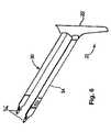
- FIG. 6is a perspective view of the support member combined with a sheath and a dilator
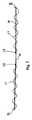
- FIG. 7is a side view of the support member showing a filament tension control member
- FIG. 8is a top view of an embodiment of the support member showing a filament tension control member
- FIG. 9is a side perspective view of the support member combined with a sheath and a dilator.
- FIG. 10is a side view of a dilator with low-profile riveted connection.
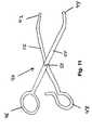
- FIG. 11is a side view of a dilator connection tool.
- FIG. 12is a fragmentary view of the support member combined with a sheath.
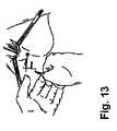
- FIG. 13illustrates the positioning of external incisions on the rectum of the patient.
- FIG. 14illustrates a method of inserting the needle in a patient.
- FIG. 15illustrates palpation to aid passage of the needle to its appropriate position.
- FIG. 16illustrates an embodiment of the connector on the end portion of the mesh.
- FIG. 17illustrates positioning of the mesh by manipulating the sheathed end portions.
- FIG. 18is a top view of the self-fixating mesh implant of the present invention.
- FIG. 19illustrates a needle with marks for implantation of the self-fixating mesh of the present invention.
- FIG. 1shows a needle 14 and handle 10 suitable for use in the present invention. Needle 14 terminates in a tip 16 . Needle 14 comprises a generally straight section 15 near handle 10 . In one embodiment, the straight section 15 shown in FIG. 1 is between about 4 inches and about 8 inches, preferably between about 5 inches and about 7 inches, more preferably between about 5.5 inches and about 6.5 inches.
- the portion of needle 14 between straight section 15 and tip 16includes a multi radii bend defined by a first radius R 1 and a second radius R 2 , distinct from the first radius.
- the first radius R 1is generally between about 2 inches and about 4 inches, preferably between about 2.5 inches and about 3.5 inches.
- the second radius R 2is generally larger than R 1 .
- R 2is between about 4 inches and about 6 inches, preferably between about 4.5 inches and 5.5 inches.
- This multi-radii bendallows for at least 1 cm of additional curvature of tip 16 for easier final passage past the ischial spine of a patient. It also enables an easier connection between the tip 16 and a mesh support structure. Moreover, the multi-radii bend provides a physician with better control of the tip 16 during a procedure.
- FIG. 2shows a needle 14 with an alternative multi-radii configuration.
- first radius R 1is on the opposite side of the needle 14 from the second radius R 2 .
- first radius R 1is smaller than the second radius R 2 .
- the tip 16 of needle 14generally lines in a line parallel to the line disposed within handle 10 .
- FIG. 3shows a needle 14 with a single-radii configuration.
- needle 14forms a single radius R 1 which terminates at tip 16 .
- Straight section 15is disposed between handle 10 and the portion where radius R 1 begins.
- the tip 16 of needle 14lines in a line generally skewed from the line disposed within handle 10 .
- FIG. 4shows an alternative embodiment of a needle 14 which includes three radii R 1 , R 2 , and R 3 .
- needle 14is attached to handle 10 and terminates in tip 16 .
- a first radiusis disposed between straight section 15 and straight section 17 .
- Straight section 15is disposed between handle 10 and first radius R 1 .
- Second radius R 2 and third radius R 3is disposed between straight section 17 and tip 16 .
- First radius R 1is on the opposite side of the needle from second radius R 2 and third radius R 3 .
- first radiusis smaller than second radius R 2 and third radius R 3 . This enables straight section 15 to be approximately perpendicular to straight section 17 .
- the tip 16 of needle 14lies in a line generally parallel to the line disposed in handle 10 .
- FIG. 5shows an alternative embodiment of the needle shown in FIG. 1 .
- FIG. 5shows a needle 14 which terminates in a tip 16 .
- Needle 14comprises a generally straight section 15 near handle 10 .
- the straight section 15 of the needle in FIG. 5is at least 2 cm shorter than the straight section of the needle shown in FIG. 1 .
- the straight section 15 shown in FIG. 5is between about 3 inches and about 7 inches, preferably between about 4 inches and about 6 inches, more preferably between about 4.5 inches and about 5.5 inches.
- the portion of needle 14 between straight section 15 and tip 16includes a multi radii bend defined by a first radius R 1 and a second radius R 2 , distinct from the first radius.
- the first radius R 1is generally between about 2 inches and about 4 inches, preferably between about 2.5 inches and about 3.5 inches.
- the second radius R 2is generally larger than R 1 .
- R 2is between about 4 inches and about 6 inches, preferably between about 4.5 inches and 5.5 inches.
- This multi-radii bendallows for at least 1 cm of additional curvature of tip 16 for easier final passage past the ischial spine of a patient. It also enables an easier connection between the tip 16 and a mesh support structure.
- the multi-radii bend, coupled with the shortened straight section 15provides a physician with increased control of the tip 16 during a procedure.
- the shortened straight section 15more easily prevents flexure of the needle 14 by providing increased rigidity.
- the shape of the needle 14should facilitate and provide controlled passage of the needle 14 through tissue as required.
- the ends or tip of the needle 14are generally not sharpened, but may be tapered to afford easy passage through tissue while providing a blunt surface that avoids cutting sensitive tissue such as the bowel.
- the diameter of the needle 14be slightly larger relative to the prior art to reduce tissue trauma and make palpation easier.
- the diameter of needle 14is between about 0.100 inches and about 0.150 inches, preferably between about 0.120 inches and about 0.130 inches, more preferably about 0.125 inches.
- the needle 14is made of a malleable, yet durable, biocompatible surgical instrument material such as, but not limited to, stainless steel, titanium, Nitinol, polymers, plastics and other materials, including combinations of materials.
- the needle 14should have sufficient structural integrity to withstand the various forces (e.g., forces caused by dilator attachment, cystoscopy aid passage, and penetration/passage of the needle 14 through the various tissues) without undergoing any significant structural deformation.
- FIGS. 1-5show needle tip 16 .
- Needle tip 16is optionally adapted to connect securely to a connector on the end of a sheath associated with as least one of the end portions of a support member.
- Many different configurations of such a systemare known in the art and within the scope of the present invention. Several configurations are disclosed in U.S. Pat. No. 6,652,450, which is incorporated herein by reference.
- FIG. 6shows an embodiment of the support member 20 of the present invention.
- the support member 20is a mesh fabric including the support portion 22 and two end portions 30 and 34 .
- the support membermay be a one piece mesh with the support portion substantially continuous with the end portions.
- Suitable non-absorbable materials for use in the present inventioninclude, but are not limited to, cotton, linen, silk, polyamides (e.g. polyhexamethylene adipamide (nylon 66), polyhexamethylene sebacamide (nylon 610), polycapramide (nylon 6), polydodecanamide (nylon 12) and polyhexamethylene isophthalamide (nylon 61) copolymers and blends thereof), polyesters (e.g.
- fluoropolymerse.g. polytetrafluoroethylene and polyvinylidene fluoride
- Suitable absorbable materials for use as yamsinclude but are not limited to aliphatic polyesters which include but are not limited to homopolymers and copolymers of lactide (which includes lactic acid and meso lactide), glycolide (including glycolic acid), epsilon.-caprolactone, p-dioxanone (1,4-dioxan-2-one), trimethylene carbonate (1,3-dioxan-2-one), alkyl derivatives of trimethylene carbonate, delta-valerolactone, beta-butyrolactone, gamma-butyrolactone, epsilon-decalactone, hydroxybutyrate, hydroxyvalerate, 1,4-dioxepan-2-one (including its dimmer 1,5,8,12-tetraoxacyclotetradecane-7,14-dionc), 1,5-dioxepan-2-one, 6,6-dimethyl-1,4-dioxan-2
- the meshis preferably fabricated from a 4.0 mil diameter monofilament polypropylene yarn by employing methods known in the art and described in “Warp Knitting Production” by Dr. S. Raz, Melliand Textilberichte GmbH, Rohrbacher Str. 76, D-6900 Heidelberg, Germany (1987), the contents of which are incorporated by reference herein.
- U.S. Pat. No. 6,638,284is also herein incorporated by reference in its entirety.
- a preferred mesh for use in the present inventionis a polypropylene mesh possessing a thickness of about 0.021 inches, has about 27.5 courses per inch, and 13 wales per inch. It has three bar warp knit construction with a bar pattern set-up of #1: 1/0, 2/3, 2/1, 2/3, 1/0, 1/2, 1/0, 1/2: #2: 1/0, 2/3, 2/3, 1/0: #3: 2/3, 1/0, 1/2, 1/0, 2/3, 2/1, 2/3, 2/1.
- the apparatus of the present inventioncan have different mesh knits in the support member and the end portions. Such a construction would allow use of the optimum knit for support or anchoring. Such an apparatus could be manufactured by use of variable knitting and/or variable heat-setting techniques.
- FIGS. 7 and 8illustrate the tension control member 27 .
- the tension control member 27serves as a repositioning means to effect tightening or loosening of the apparatus without adversely affecting the therapeutic efficacy of the apparatus.
- tension control member 27is a monofilament fiber woven into the support member and attached to the support member via attachment points 28 located near the support portion 22 of the support member.
- the tension control memberenables surgeons to easily increase (tighten) or decrease (loosen) the support member tension during the surgical procedure.
- the surgeoncontacts the support member and tension control member 27 adjacent the prolapsed organ and pulls away from the organ.
- the tension of the central portionmay be increased by grasping the support member and tension control member 27 above the vaginal incision and pulling upward.
- One or both end portions of the support member, and tension control membermay be grasped to increase the tension of the support member, effecting tightening by pulling the end portions out at the incisions in the buttocks. Affording adjustment of the support member facilitates proper support member placement and helps avoid complications such as recurrence and tissue erosion arising out of improper placement.
- the individual fibers or filaments comprising the tension control membermay be extruded, woven, braided, spun, knitted, non-woven or have other similar configurations.
- Tension control member propertiessuch as tensile strength, elongation at break point, stiffness, surface finish, etc., may be similar to or different from those of the support member and may vary along the length of the support member.
- FIGS. 6 and 9show a mesh/sheath assembly.
- the end portions 32 of the support memberare substantially enclosed by a sheath 34 .
- the sheathacts to ease the passage of the mesh end portions 32 through the tissue and to protect the mesh from deformation.
- the sheath 34further serves to maintain the mesh in a more sterile condition because, prior to removal of the sheath, the mesh itself has not contacted the vagina.
- the sheath 34further provides a means of adjusting the positioning of the support member through manual manipulation of the sheath 34 before their removal.
- the sheath 34may optionally further comprise a connecting mechanism to affect a secure attachment to the end of the needle.
- a preferred embodimentcomprises a loop for attachment of the end portions to the needle. This loop is enlarged to allow a surgeon to place his finger through the loop and push the connector onto the needle.
- FIG. 10shows the attachment of the dilator 36 to the end portion 33 of the support member.
- a transition zone 35is disposed between end portion 33 and dilator 36 .
- Transition zone 35is comprised of a riveted synthetic cape which provides a tapered transition from end portion 33 to dilator 36 .
- transition zone 35is at least partially disposed inside dilator 36 . This configuration helps minimize snagging of pelvic tissue on the transition zone 35 and end portion 33 as the dilator 36 is pulled through tissue.
- FIG. 11discloses a tool 40 for securing dilator 36 onto tip 16 of needle 14 .
- Tool 40includes a first member 52 rotatably fastened to a second member 54 at a fulcrum 50 .
- First member 52is generally elongated and includes a first handle 48 at one end and a first support surface 42 at the other end.
- second member 54is generally elongated and includes a second handle 46 at one end and a second support surface 44 at the other end.
- dilator 36can be supported by first support surface 42 while tip 16 is supported by second support surface 44 .
- handle 46is moved closer to handle 48 , needle tip 16 is secured to dilator 36 , thereby enabling the support structure to be manipulated as the needles 14 are removed from the pelvic tissue.
- FIG. 18discloses a self-fixating mesh implant of the present invention.
- the implant 55includes a middle portion 56 .
- the implant 55also includes one or more pairs of legs 57 extending out from the middle portion 56 to the right and left.
- Posterior legs 59may extend in a forward and/or rearward direction to provide needed support.
- the meshmay be fixed without the use of sutures either by relying on the properties of the mesh material itself or by adding a tissue anchor 60 to an end of at least one of the arms of the mesh.
- FIG. 19discloses a tool for implanting the self-fixating mesh implant 55 of the present invention.
- the toolincludes a handle 10 and a needle 14 .
- the needlehas markings 58 to indicate the depth for implantation of the implant 55 , based on the anatomical placement for each leg.
- the needle tipis optionally adapted to connect to an anchor or dilator to ease placement of the mesh arms.
- the procedurecan be carried out under local or general anesthesia.
- An incisionis made midline across the vaginal apex with sharp and blunt dissection to the ischial spine.
- Two small incisionsare also made in the skin of the buttocks. Needles are passed from perianal skin incisions in the buttocks through the ischial rectal fossa to the vaginal incision. The needle tip is palpated distal and inferior to the ischial spine prior to passage through the coccygeus muscle. Further dissection may be desired to aid palpation of the needle passage.
- Connectorsare connected to each needle end. Needles are retracted and mesh is positioned. The mesh is then attached to the vaginal vault, and optionally to the lateral perirectal space or perineal body, tensioned, and the incisions are closed.
- One embodiment of the present inventionis a sterile, single use product consisting of two stainless steel curved needles and a polypropylene mesh implant.
- the same polypropylene meshis available in an alternative configuration that allows the attachment of biological material.
- Locking connectors on the ends of the meshattach to each needle tip and are used to hold the mesh secure to the needle during passage of the mesh through the body.
- the connectorsmay be removed, if desired.
- the physicianmay decide at his/her discretion which configuration is most appropriate for a particular patient.
- a first embodiment(described herein as the tape embodiment) includes one-piece self-fixating mesh two removable plastic insertion sheaths over the mesh, and two locking connectors attached to the insertion sheaths.
- the tapeis knitted polypropylene monofilament mesh that is pre-cut to 1.1 cm width ⁇ 50 cm length with a non-absorbable or absorbable tensioning suture (polypropylene) threaded through the length to allow for tensioning adjustment after placement.
- the sheathaffords convenient travel of the mesh through the tissue. Finger loops are formed by the sheath to allow for easy attachment of the connectors to the needle tips.
- the synthetic mesh tapeis intended to remain in the body as a permanent implant.
- a second embodiment(described herein as the cape embodiment) adds a 4 cm ⁇ 13 cm mesh to the tape.
- This soft knitted meshhas large pores and is also made of polypropylene. The mesh is pre-attached to the tape and can be trimmed to suit surgical preference.
- a third embodiment(described herein as the bio-cape embodiment) consists of two separate 1.1 cm ⁇ 22 cm polypropylene mesh pieces, using the same material as in the tape version. However, one end has a locking connector and finger loop and the other end has a plastic clamp attached to a Y-shaped mesh used to facilitate attachment to a biological implant. The clamp is designed to facilitate the attachment of graft material with sutures.
- the patientIn order to use the present invention in treatment of pelvic organ prolapse, the patient should initially be prepared by placing the patient in a modified dorsal lithotomy position with hips flexed, legs elevated in stirrups, and buttocks even with the edge of the table. Vaginal retraction may be used, if desired. Palpate the location of the ischial spines.
- the fourth main embodiment of the present inventionis a self-fixating mesh implant having a middle portion and several pairs of legs extending therefrom, in which the arms are designed to be fixed into supportive tissue by tissue anchors or by the material characteristics of the mesh itself.
- the processincludes steps to gain access to the target organ.
- the stepsmay include:
- the inventionmay include a kit, apparatus, and method with only one needle. In these alternative embodiments, it is necessary to:
Landscapes
- Health & Medical Sciences (AREA)
- Life Sciences & Earth Sciences (AREA)
- Surgery (AREA)
- Veterinary Medicine (AREA)
- General Health & Medical Sciences (AREA)
- Biomedical Technology (AREA)
- Heart & Thoracic Surgery (AREA)
- Engineering & Computer Science (AREA)
- Public Health (AREA)
- Animal Behavior & Ethology (AREA)
- Medical Informatics (AREA)
- Molecular Biology (AREA)
- Nuclear Medicine, Radiotherapy & Molecular Imaging (AREA)
- Urology & Nephrology (AREA)
- Cardiology (AREA)
- Oral & Maxillofacial Surgery (AREA)
- Transplantation (AREA)
- Vascular Medicine (AREA)
- Prostheses (AREA)
Abstract
Description
- (1) Gaining access to the external vaginal vault using surgeon's preferred method of incision and dissection. If the cape is used, complete rectovaginal dissection may be required.
- (2) Making the appropriate incisions. In a preferred method, two small stab incisions are made on each side of the rectum approximately 3 cm lateral and 3 cm posterior to the anus, as shown in
FIG. 13 . - (3) Grasping the needle in one hand with the needle tip between the thumb and forefinger. Place the other hand near the needle bend. The two needles are identical. Either side may be done first.
- (4) Pointing the needle tip perpendicular to the skin with the handle pointing upward in a 12:00 position, as shown in
FIG. 14 . - (5) Directing the needle at a slight upward and lateral angle through the buttock. Puncture the initial layers of tissue by pushing on the needle bend until the needle enters the ischiorectal fossa.
- (6) Continuing to pass the needle tip lateral and parallel to the rectum toward the ischial spine. Palpate as needed, as shown in
FIG. 15 . - (7) Palpating the needle tip in front of the ischial spine. Penetrate the levator muscle advancing and lightly turning the needle tip medially toward the vaginal vault.
- (8) Performing digital rectal exam to verify rectal integrity.
- (9) Repeating steps 3-9 on patient's contralateral side.
- (10) Inserting a finger into the loop behind the connector on the mesh, as shown in
FIG. 16 . Insert the connector into the vagina. Snap onto the needle tip. - (11) Pulling each needle and connector back through the skin incision. Adjust the sheath and mesh into an approximate position.
- (12) Cutting the needles from the mesh near the end of the sheath, below the blue dots provided to guide the surgeon.
- (13) Attaching the mesh to the exterior apex of the vaginal wall with two or more sutures.
- (14) Ensuring the vaginal wall is in the appropriate anatomic position. If the cape is being used, lay the cape in the perirectal space, in a tension-free manner, and close the perirectal fascia over the mesh or the vaginal incision.
- (15) Pulling on the mesh assemblies to make final adjustments, as shown in
FIG. 17 . - (16) Removing plastic sheaths.
- (17) Trimming the mesh at the level of the subcutaneous tissue.
- (18) Closing the incisions.
- (19) Using a vaginal pack and antibiotic prophylaxis as appropriate.
- (1) Gain access to the external vaginal vault using surgeon's preferred method of incision and dissection. If the cape is used, complete rectovaginal dissection is required.
- (2) Make two small stab incisions on each side of the rectum approximately 3 cm lateral and 3 cm posterior to the anus, as shown in
FIG. 13 . - (3) Grasp the needle in one hand with the needle tip between the thumb and forefinger. Place the other hand near the needle bend.
- (4) Point the needle tip perpendicular to the skin with the handle pointing upward in a 12:00 position, as shown in
FIG. 14 . - (5) Direct the needle at a slight upward and lateral angle through the buttock. Puncture the initial layers of tissue by pushing on the needle bend until the needle enters the ischiorectal fossa.
- (6) Continue to pass the needle tip lateral and parallel to the rectum toward the ischial spine. Palpate as needed, as shown in
FIG. 15 . - (7) Palpate the needle tip in front of the ischial spine. Penetrate the levator muscle advancing and lightly turning the needle tip medially toward the vaginal vault.
- (8) Perform digital rectal exam to verify rectal integrity.
- (9) Repeat steps 3-9 with the single needle on the patient's contralateral side.
- (10) Insert a finger into the loop behind the connector on the mesh, as shown in
FIG. 16 . - (11) Pull the needle and connector back through each skin incision. Adjust the sheath and mesh into an approximate position.
- (12) Attach the mesh to the exterior apex of the vaginal wall with two or more sutures.
- (13) Ensure the vaginal wall is in the appropriate anatomic position. If the cape is being used, lay the cape in the perirectal space, in a tension-free manner, and close the perirectal fascia over the mesh or the vaginal incision.
- (14) Pull on the mesh assemblies to make final adjustments, as shown in
FIG. 17 . - (15) Remove plastic sheaths.
- (16) Trim the mesh at the level of the subcutaneous tissue.
- (17) Close the incisions.
- (18) Use the vaginal pack and antibiotic prophylaxis as appropriate.
Claims (17)
Priority Applications (2)
| Application Number | Priority Date | Filing Date | Title |
|---|---|---|---|
| US11/518,932US7811222B2 (en) | 2004-04-30 | 2006-09-12 | Method and apparatus for treating pelvic organ prolapse |
| US12/855,792US8206281B2 (en) | 2004-04-30 | 2010-08-13 | Method and apparatus for treating pelvic organ prolapse |
Applications Claiming Priority (4)
| Application Number | Priority Date | Filing Date | Title |
|---|---|---|---|
| US10/834,943US7500945B2 (en) | 2004-04-30 | 2004-04-30 | Method and apparatus for treating pelvic organ prolapse |
| US10/840,646US7351197B2 (en) | 2004-05-07 | 2004-05-07 | Method and apparatus for cystocele repair |
| US71611005P | 2005-09-12 | 2005-09-12 | |
| US11/518,932US7811222B2 (en) | 2004-04-30 | 2006-09-12 | Method and apparatus for treating pelvic organ prolapse |
Related Parent Applications (2)
| Application Number | Title | Priority Date | Filing Date |
|---|---|---|---|
| US10/834,943Continuation-In-PartUS7500945B2 (en) | 2004-04-30 | 2004-04-30 | Method and apparatus for treating pelvic organ prolapse |
| US10/840,646Continuation-In-PartUS7351197B2 (en) | 2004-04-30 | 2004-05-07 | Method and apparatus for cystocele repair |
Related Child Applications (1)
| Application Number | Title | Priority Date | Filing Date |
|---|---|---|---|
| US12/855,792DivisionUS8206281B2 (en) | 2004-04-30 | 2010-08-13 | Method and apparatus for treating pelvic organ prolapse |
Publications (2)
| Publication Number | Publication Date |
|---|---|
| US20070068538A1 US20070068538A1 (en) | 2007-03-29 |
| US7811222B2true US7811222B2 (en) | 2010-10-12 |
Family
ID=46326075
Family Applications (2)
| Application Number | Title | Priority Date | Filing Date |
|---|---|---|---|
| US11/518,932Active2026-05-20US7811222B2 (en) | 2004-04-30 | 2006-09-12 | Method and apparatus for treating pelvic organ prolapse |
| US12/855,792Expired - Fee RelatedUS8206281B2 (en) | 2004-04-30 | 2010-08-13 | Method and apparatus for treating pelvic organ prolapse |
Family Applications After (1)
| Application Number | Title | Priority Date | Filing Date |
|---|---|---|---|
| US12/855,792Expired - Fee RelatedUS8206281B2 (en) | 2004-04-30 | 2010-08-13 | Method and apparatus for treating pelvic organ prolapse |
Country Status (1)
| Country | Link |
|---|---|
| US (2) | US7811222B2 (en) |
Families Citing this family (26)
| Publication number | Priority date | Publication date | Assignee | Title |
|---|---|---|---|---|
| JP2009515564A (en)* | 2005-08-04 | 2009-04-16 | シー・アール・バード・インコーポレイテツド | Pelvic implant system and method |
| WO2007059199A2 (en) | 2005-11-14 | 2007-05-24 | C.R. Bard, Inc. | Sling anchor system |
| JP2009528851A (en)* | 2005-12-28 | 2009-08-13 | シー・アール・バード・インコーポレイテツド | Apparatus and method for inserting an implant |
| WO2007109062A2 (en)* | 2006-03-15 | 2007-09-27 | C.R. Bard, Inc. | Implants for the treatment of pelvic floor disorders |
| US8585733B2 (en)* | 2006-04-19 | 2013-11-19 | Vibrynt, Inc | Devices, tools and methods for performing minimally invasive abdominal surgical procedures |
| US20090281386A1 (en)* | 2006-04-19 | 2009-11-12 | Acosta Pablo G | Devices, system and methods for minimally invasive abdominal surgical procedures |
| US20090281500A1 (en)* | 2006-04-19 | 2009-11-12 | Acosta Pablo G | Devices, system and methods for minimally invasive abdominal surgical procedures |
| US20090281563A1 (en)* | 2006-04-19 | 2009-11-12 | Newell Matthew B | Devices, tools and methods for performing minimally invasive abdominal surgical procedures |
| US20090275972A1 (en)* | 2006-04-19 | 2009-11-05 | Shuji Uemura | Minimally-invasive methods for implanting obesity treatment devices |
| US20090272388A1 (en)* | 2006-04-19 | 2009-11-05 | Shuji Uemura | Minimally-invasive methods for implanting obesity treatment devices |
| US7976554B2 (en)* | 2006-04-19 | 2011-07-12 | Vibrynt, Inc. | Devices, tools and methods for performing minimally invasive abdominal surgical procedures |
| US20090281376A1 (en)* | 2006-04-19 | 2009-11-12 | Acosta Pablo G | Devices, system and methods for minimally invasive abdominal surgical procedures |
| WO2008033950A2 (en) | 2006-09-13 | 2008-03-20 | C. R. Bard, Inc. | Urethral support system |
| US20080234543A1 (en)* | 2007-03-23 | 2008-09-25 | Jjamm, Llc | Surgical devices and method for vaginal prolapse repair |
| CA2941002A1 (en) | 2007-07-16 | 2009-01-22 | Ams Research Corporation | Surgical devices and methods for treating pelvic conditions |
| CA2695212C (en)* | 2007-07-30 | 2017-11-28 | Boston Scientific Scimed, Inc. | Apparatus and method for the treatment of stress urinary incontinence |
| US8206280B2 (en) | 2007-11-13 | 2012-06-26 | C. R. Bard, Inc. | Adjustable tissue support member |
| US8727963B2 (en)* | 2008-07-31 | 2014-05-20 | Ams Research Corporation | Methods and implants for treating urinary incontinence |
| US8382775B1 (en) | 2012-01-08 | 2013-02-26 | Vibrynt, Inc. | Methods, instruments and devices for extragastric reduction of stomach volume |
| US9314362B2 (en) | 2012-01-08 | 2016-04-19 | Vibrynt, Inc. | Methods, instruments and devices for extragastric reduction of stomach volume |
| US10278694B2 (en) | 2012-02-23 | 2019-05-07 | Northwestern University | Indirect attachment of a needle to a mesh suture |
| ES2655821T3 (en) | 2012-02-23 | 2018-02-21 | Northwestern University | Enhanced Suture |
| USD760898S1 (en)* | 2015-05-06 | 2016-07-05 | VTrump Tech (Shanghai) Co., Ltd. | Kegel exercising device |
| CN111432749B (en) | 2017-10-19 | 2023-04-04 | C.R.巴德公司 | Self-gripping hernia prosthesis |
| WO2019108261A1 (en)* | 2017-11-29 | 2019-06-06 | Northwestern University | Indirect attachment of a needle to a mesh suture |
| IT201800009068A1 (en)* | 2018-10-01 | 2020-04-01 | Azzam Khader | SURGICAL DEVICE FOR TREATMENT OF PELVIC PROLAPSE |
Citations (4)
| Publication number | Priority date | Publication date | Assignee | Title |
|---|---|---|---|---|
| US6053935A (en)* | 1996-11-08 | 2000-04-25 | Boston Scientific Corporation | Transvaginal anchor implantation device |
| US20020099259A1 (en)* | 2001-01-23 | 2002-07-25 | Anderson Kimberly A. | Surgical instrument and method |
| US20040039246A1 (en)* | 2001-07-27 | 2004-02-26 | Barry Gellman | Medical slings |
| US7094199B2 (en)* | 2002-07-23 | 2006-08-22 | Sherwood Services Ag | Ivs obturator instrument and procedure |
Family Cites Families (173)
| Publication number | Priority date | Publication date | Assignee | Title |
|---|---|---|---|---|
| US3124136A (en)* | 1964-03-10 | Method of repairing body tissue | ||
| US2738790A (en)* | 1954-08-12 | 1956-03-20 | George P Pilling & Son Company | Suturing instrument |
| US3182662A (en)* | 1962-07-25 | 1965-05-11 | Vithal N Shirodkar | Plastic prosthesis useful in gynaecological surgery |
| US3384073A (en)* | 1964-04-21 | 1968-05-21 | Ethicon Inc | Surgical device for correction of urinary incontinence |
| US3311110A (en)* | 1964-07-15 | 1967-03-28 | American Cyanamid Co | Flexible composite suture having a tandem linkage |
| US3472232A (en) | 1967-05-31 | 1969-10-14 | Abbott Lab | Catheter insertion device |
| US3580313A (en)* | 1969-01-07 | 1971-05-25 | Mcknight Charles A | Surgical instrument |
| US3763860A (en) | 1971-08-26 | 1973-10-09 | H Clarke | Laparoscopy instruments and method for suturing and ligation |
| US3789828A (en)* | 1972-09-01 | 1974-02-05 | Heyer Schulte Corp | Urethral prosthesis |
| US3858783A (en)* | 1972-11-20 | 1975-01-07 | Nikolai Nikolaevich Kapitanov | Surgical instrument for stitching up tissues with lengths of suture wire |
| DE2305815A1 (en) | 1973-02-07 | 1974-08-08 | Kurt Seuberth | DEVICE FOR SEPARATING SURGICAL FEEDS |
| US3924633A (en) | 1974-01-31 | 1975-12-09 | Cook Inc | Apparatus and method for suprapubic catheterization |
| US4037603A (en)* | 1975-05-13 | 1977-07-26 | Wendorff Erwin R | Metallic surgical suture |
| US3995619A (en) | 1975-10-14 | 1976-12-07 | Glatzer Stephen G | Combination subcutaneous suture remover, biopsy sampler and syringe |
| US4019499A (en)* | 1976-04-22 | 1977-04-26 | Heyer-Schulte Corporation | Compression implant for urinary incontinence |
| US4128100A (en) | 1976-10-08 | 1978-12-05 | Wendorff Erwin R | Suture |
| SU715082A1 (en)* | 1977-01-24 | 1980-02-15 | Всесоюзный научно-исследовательский и испытательный институт медицинской техники | Surgical suturing apparatus |
| US5633286B1 (en)* | 1977-03-17 | 2000-10-10 | Applied Elastomerics Inc | Gelatinous elastomer articles |
| US4172458A (en) | 1977-11-07 | 1979-10-30 | Pereyra Armand J | Surgical ligature carrier |
| US4235238A (en) | 1978-05-11 | 1980-11-25 | Olympus Optical Co., Ltd. | Apparatus for suturing coeliac tissues |
| US4246660A (en)* | 1978-12-26 | 1981-01-27 | Queen's University At Kingston | Artificial ligament |
| US4265231A (en)* | 1979-04-30 | 1981-05-05 | Scheller Jr Arnold D | Curved drill attachment for bone drilling uses |
| SU1342486A1 (en) | 1982-06-29 | 1987-10-07 | М.А. Мороз | Needle holder |
| US4441497A (en)* | 1982-10-21 | 1984-04-10 | Paudler Franklin T | Universal suture passer |
| US4509516A (en)* | 1983-02-24 | 1985-04-09 | Stryker Corporation | Ligament tunneling instrument |
| US4865031A (en) | 1985-07-12 | 1989-09-12 | Keeffe Paul J O | Fabric and method of use for treatment of scars |
| US4632100A (en) | 1985-08-29 | 1986-12-30 | Marlowe E. Goble | Suture anchor assembly |
| GB8525565D0 (en) | 1985-10-17 | 1985-11-20 | Speedhom B B | Surgical replacement of ligaments |
| GB8611129D0 (en)* | 1986-05-07 | 1986-06-11 | Annis D | Prosthetic materials |
| US5386836A (en)* | 1986-10-14 | 1995-02-07 | Zedlani Pty Limited | Urinary incontinence device |
| US4920986A (en)* | 1986-10-14 | 1990-05-01 | Zedlani Pty. Limited | Urinary incontinence device |
| DE68921762T2 (en)* | 1988-10-04 | 1995-08-03 | Peter Emmanuel Petros | SURGICAL INSTRUMENT, PROSTHESIS. |
| US5123428A (en)* | 1988-10-11 | 1992-06-23 | Schwarz Gerald R | Laparoscopically implanting bladder control apparatus |
| US5013292A (en) | 1989-02-24 | 1991-05-07 | R. Laborie Medical Corporation | Surgical correction of female urinary stress incontinence and kit therefor |
| GB8924806D0 (en)* | 1989-11-03 | 1989-12-20 | Neoligaments Ltd | Prosthectic ligament system |
| US5256133A (en) | 1990-09-05 | 1993-10-26 | Spitz Robert M | Device for correcting stress urinary incontinence |
| US5368595A (en) | 1990-09-06 | 1994-11-29 | United States Surgical Corporation | Implant assist apparatus |
| US5053043A (en) | 1990-09-28 | 1991-10-01 | Vance Products Incorporated | Suture guide and method of placing sutures through a severed duct |
| US5085661A (en)* | 1990-10-29 | 1992-02-04 | Gerald Moss | Surgical fastener implantation device |
| JPH06506366A (en)* | 1990-12-06 | 1994-07-21 | ダブリュ.エル.ゴア アンド アソシエーツ,インコーポレイティド | Implantable bioabsorbable components |
| US5439467A (en)* | 1991-12-03 | 1995-08-08 | Vesica Medical, Inc. | Suture passer |
| CA2181674A1 (en)* | 1991-12-03 | 1993-10-04 | Theodore V. Benderev | Support structure for supporting and positioning medical equipment |
| WO1993010715A2 (en) | 1991-12-03 | 1993-06-10 | Vesitec Medical, Inc. | Surgical treatment of stress urinary incontinence |
| US5935122A (en)* | 1991-12-13 | 1999-08-10 | Endovascular Technologies, Inc. | Dual valve, flexible expandable sheath and method |
| WO1993017635A1 (en) | 1992-03-04 | 1993-09-16 | C.R. Bard, Inc. | Composite prosthesis and method for limiting the incidence of postoperative adhesions |
| US5403328A (en)* | 1992-04-22 | 1995-04-04 | United States Surgical Corporation | Surgical apparatus and method for suturing body tissue |
| US5188636A (en)* | 1992-05-07 | 1993-02-23 | Ethicon, Inc. | Purse string suture instrument |
| US5207694A (en)* | 1992-06-18 | 1993-05-04 | Surgical Invent Ab | Method for performing a surgical occlusion, and kit and applicator for carrying out the method |
| DE4220283C2 (en) | 1992-06-20 | 1994-05-19 | Singer Spezialnadelfab | Surgical needle-thread combination |
| US6048351A (en)* | 1992-09-04 | 2000-04-11 | Scimed Life Systems, Inc. | Transvaginal suturing system |
| US5362294A (en) | 1992-09-25 | 1994-11-08 | Seitzinger Michael R | Sling for positioning internal organ during laparoscopic surgery and method of use |
| US5281237A (en)* | 1992-09-25 | 1994-01-25 | Gimpelson Richard J | Surgical stitching device and method of use |
| US5337736A (en)* | 1992-09-30 | 1994-08-16 | Reddy Pratap K | Method of using a laparoscopic retractor |
| US5383904A (en)* | 1992-10-13 | 1995-01-24 | United States Surgical Corporation | Stiffened surgical device |
| DE4304353A1 (en) | 1992-10-24 | 1994-04-28 | Helmut Dipl Ing Wurster | Suturing device used in endoscopic surgical operations - has helical needle with fixed non-traumatic thread held and rotated by rollers attached to instrument head extended into patients body. |
| US5250033A (en) | 1992-10-28 | 1993-10-05 | Interventional Thermodynamics, Inc. | Peel-away introducer sheath having proximal fitting |
| US5972000A (en)* | 1992-11-13 | 1999-10-26 | Influence Medical Technologies, Ltd. | Non-linear anchor inserter device and bone anchors |
| IL103737A (en)* | 1992-11-13 | 1997-02-18 | Technion Res & Dev Foundation | Stapler device particularly useful in medical suturing |
| US6406480B1 (en)* | 1992-11-13 | 2002-06-18 | American Med Syst | Bone anchor inserter with retractable shield |
| US5328077A (en)* | 1992-11-19 | 1994-07-12 | Lou Ek Seng | Method and apparatus for treating female urinary incontinence |
| US5540703A (en)* | 1993-01-06 | 1996-07-30 | Smith & Nephew Richards Inc. | Knotted cable attachment apparatus formed of braided polymeric fibers |
| US5336239A (en)* | 1993-01-15 | 1994-08-09 | Gimpelson Richard J | Surgical needle |
| JPH08502438A (en) | 1993-02-22 | 1996-03-19 | ヴァリーラブ・インコーポレーテッド | Laparoscopic distraction tension retractor device and method |
| WO1994021197A1 (en)* | 1993-03-25 | 1994-09-29 | C.R. Bard, Inc. | Vascular graft |
| US5520703A (en)* | 1993-06-07 | 1996-05-28 | Essig; Mitchell N. | Laparoscopic deschamp and associated suturing technique |
| BR9302774A (en) | 1993-07-06 | 1995-02-14 | Antoine Jean Henri Robert | Adjustable peri-urethral expander |
| CA2124651C (en) | 1993-08-20 | 2004-09-28 | David T. Green | Apparatus and method for applying and adjusting an anchoring device |
| AU1011595A (en)* | 1994-01-13 | 1995-07-20 | Ethicon Inc. | Spiral surgical tack |
| FR2720266B1 (en)* | 1994-05-27 | 1996-12-20 | Cogent Sarl | Prosthetic fabric. |
| US5582616A (en) | 1994-08-05 | 1996-12-10 | Origin Medsystems, Inc. | Surgical helical fastener with applicator |
| SE506164C2 (en) | 1995-10-09 | 1997-11-17 | Medscand Medical Ab | Instruments for the treatment of urinary incontinence in women |
| US5899909A (en)* | 1994-08-30 | 1999-05-04 | Medscand Medical Ab | Surgical instrument for treating female urinary incontinence |
| US5562685A (en) | 1994-09-16 | 1996-10-08 | General Surgical Innovations, Inc. | Surgical instrument for placing suture or fasteners |
| US5571139A (en) | 1995-05-19 | 1996-11-05 | Jenkins, Jr.; Joseph R. | Bidirectional suture anchor |
| US5591163A (en)* | 1995-06-14 | 1997-01-07 | Incont, Inc. | Apparatus and method for laparoscopic urethropexy |
| US5997554A (en) | 1995-06-14 | 1999-12-07 | Medworks Corporation | Surgical template and surgical method employing same |
| US5669935A (en) | 1995-07-28 | 1997-09-23 | Ethicon, Inc. | One-way suture retaining device for braided sutures |
| US5662683A (en) | 1995-08-22 | 1997-09-02 | Ortho Helix Limited | Open helical organic tissue anchor and method of facilitating healing |
| AUPN562295A0 (en)* | 1995-09-26 | 1995-10-19 | Compton, Jeffrey Spencer Dr | Easy load device for raney style scalp clips |
| WO1997016121A1 (en) | 1995-10-31 | 1997-05-09 | Karl Christopher Texler | Surgical instruments |
| DE19544162C1 (en) | 1995-11-17 | 1997-04-24 | Ethicon Gmbh | Implant for suspension of the bladder in urinary incontinence in women |
| EP0950385A3 (en)* | 1995-12-14 | 1999-10-27 | Prograft Medical, Inc. | Stent-graft deployment apparatus and method |
| ES1035671Y (en) | 1996-11-21 | 1997-11-16 | Brucart Puig Ramon | CORKSCREW WITH DOUBLE SUPPORT POINT. |
| AU6329498A (en) | 1997-02-13 | 1998-09-08 | Boston Scientific Ireland Limited, Barbados Head Office | Percutaneous and hiatal devices and methods for use in minimally invasive pelvicsurgery |
| AU6329598A (en) | 1997-02-13 | 1998-09-08 | Boston Scientific Ireland Limited, Barbados Head Office | Stabilization sling for use in minimally invasive pelvic surgery |
| AU6171798A (en) | 1997-02-13 | 1998-09-08 | Boston Scientific Ireland Limited, Barbados Head Office | Method and apparatus for minimally invasive pelvic surgery |
| US6599235B2 (en)* | 1997-03-18 | 2003-07-29 | American Medical Systems Inc. | Transvaginal bone anchor implantation device |
| US6039686A (en)* | 1997-03-18 | 2000-03-21 | Kovac; S. Robert | System and a method for the long term cure of recurrent urinary female incontinence |
| US5934283A (en)* | 1997-04-15 | 1999-08-10 | Uroplasty, Inc. | Pubovaginal sling device |
| US6050935A (en)* | 1997-05-09 | 2000-04-18 | Biofertec | Container assembly for intravaginal fertilization and culture and embryo transfer and method of intravaginal fertilization and culture employing such a container |
| US6419624B1 (en) | 1999-10-11 | 2002-07-16 | Uromedica, Inc. | Apparatus and method for inserting an adjustable implantable genitourinary device |
| US5988171A (en) | 1997-06-26 | 1999-11-23 | Influence Medical Technologies, Ltd. | Methods and devices for the treatment of airway obstruction, sleep apnea and snoring |
| US5944732A (en)* | 1997-08-27 | 1999-08-31 | Medical Components, Inc. | Subcutaneous tunnelling device and methods of forming a subcutaneous tunnel |
| US5935138A (en)* | 1997-09-24 | 1999-08-10 | Ethicon, Inc. | Spiral needle for endoscopic surgery |
| ES2154133B1 (en)* | 1998-02-17 | 2001-12-01 | Puig Ramon Brucart | MULTIPURPOSE SACACORCHOS. |
| US6068591A (en)* | 1998-02-17 | 2000-05-30 | Bruckner; Norman I. | Pubo-urethral support harness apparatus for percutaneous treatment of female stress urinary incontinence |
| US6221005B1 (en)* | 1998-02-17 | 2001-04-24 | Norman I. Bruckner | Pubo-urethral support harness apparatus for percutaneous treatment of female stress urinary incontinence with urethal hypemobility |
| ES2149091B1 (en) | 1998-03-10 | 2001-05-16 | Gil Vernet Vila Jose Maria | DEVICE FOR FIXING AND ADJUSTABLE SUPPORT AT HEIGHT OF INTERNAL ANATOMICAL ORGANS. |
| US6106545A (en) | 1998-04-16 | 2000-08-22 | Axya Medical, Inc. | Suture tensioning and fixation device |
| US6382214B1 (en)* | 1998-04-24 | 2002-05-07 | American Medical Systems, Inc. | Methods and apparatus for correction of urinary and gynecological pathologies including treatment of male incontinence and female cystocele |
| US6010447A (en)* | 1998-07-31 | 2000-01-04 | Kardjian; Paul M. | Bladder sling |
| US6042536A (en)* | 1998-08-13 | 2000-03-28 | Contimed, Inc. | Bladder sling |
| US6648903B1 (en) | 1998-09-08 | 2003-11-18 | Pierson, Iii Raymond H. | Medical tensioning system |
| US6030393A (en)* | 1998-09-15 | 2000-02-29 | Corlew; Earvin L. | Needle and procedure for relieving urinary incontinence |
| US6050937A (en)* | 1998-09-21 | 2000-04-18 | Benderev; Theodore V. | Surgical tension/pressure monitor |
| US6302840B1 (en) | 1998-09-21 | 2001-10-16 | Theodore V. Benderev | Surgical monitor |
| EP1117342B1 (en) | 1998-10-01 | 2005-11-09 | Burger, Nicolaas Daniel Lombard | Distensible sling for urinary incontinence |
| US6099538A (en)* | 1999-02-02 | 2000-08-08 | T.A.G. Medical Products | Set of surgical tools and surgical method for connecting soft bone parts to one another or to connective tissue |
| US6287316B1 (en) | 1999-03-26 | 2001-09-11 | Ethicon, Inc. | Knitted surgical mesh |
| FR2792824B1 (en) | 1999-04-27 | 2001-06-22 | Sofradim Production | DEVICE FOR TREATING PROLAPSUS BY VAGINAL SUSPENSION |
| IL130307A0 (en) | 1999-06-04 | 2000-06-01 | Influence Med Tech Ltd | Bone suturing device |
| US6932759B2 (en) | 1999-06-09 | 2005-08-23 | Gene W. Kammerer | Surgical instrument and method for treating female urinary incontinence |
| US6273852B1 (en) | 1999-06-09 | 2001-08-14 | Ethicon, Inc. | Surgical instrument and method for treating female urinary incontinence |
| US7121997B2 (en)* | 1999-06-09 | 2006-10-17 | Ethicon, Inc. | Surgical instrument and method for treating female urinary incontinence |
| US7226407B2 (en) | 1999-06-09 | 2007-06-05 | Ethicon, Inc. | Surgical instrument and method for treating female urinary incontinence |
| JP4290363B2 (en) | 1999-06-09 | 2009-07-01 | エシコン・インコーポレイテッド | Method and apparatus for conditioning flexible medical polymer implants |
| US6475139B1 (en) | 1999-06-09 | 2002-11-05 | Ethicon, Inc. | Visually-directed surgical instrument and method for treating female urinary incontinence |
| US6168611B1 (en)* | 1999-09-08 | 2001-01-02 | Syed Rizvi | Suturing needle assemblies and methods of use thereof |
| AUPQ362199A0 (en) | 1999-10-22 | 1999-11-18 | Kaladelfos, George | Intra-vaginal sling placement device |
| US6626917B1 (en) | 1999-10-26 | 2003-09-30 | H. Randall Craig | Helical suture instrument |
| US6599318B1 (en) | 1999-11-30 | 2003-07-29 | Shlomo Gabbay | Implantable support apparatus and method of using same |
| US6306079B1 (en) | 1999-12-07 | 2001-10-23 | Arnaldo F. Trabucco | Mesh pubovaginal sling |
| DE19961218A1 (en)* | 1999-12-15 | 2001-07-05 | Ethicon Gmbh | Surgical needle for implanting a band |
| FR2802798B1 (en) | 1999-12-22 | 2002-02-01 | Promedon S A | PAD STRAP FOR THE TREATMENT OF URINARY INCONTINENCE |
| GB2359256B (en)* | 2000-01-21 | 2004-03-03 | Sofradim Production | Percutaneous device for treating urinary stress incontinence in women using a sub-urethral tape |
| US6406423B1 (en)* | 2000-01-21 | 2002-06-18 | Sofradim Production | Method for surgical treatment of urinary incontinence and device for carrying out said method |
| DE10004832A1 (en) | 2000-01-31 | 2001-08-16 | Ethicon Gmbh | Flat implant with X-ray visible elements |
| US7131943B2 (en) | 2000-03-09 | 2006-11-07 | Ethicon, Inc. | Surgical instrument and method for treating organ prolapse conditions |
| ATE407627T1 (en) | 2000-04-18 | 2008-09-15 | Orthopaedic Biosystems Ltd Inc | DEVICE FOR SEWING FABRIC |
| DE10019604C2 (en) | 2000-04-20 | 2002-06-27 | Ethicon Gmbh | implant |
| US6482214B1 (en) | 2000-04-27 | 2002-11-19 | Medtronic, Inc. | Intravascular seal with mesh reinforcement and method for using same |
| US6596001B2 (en)* | 2000-05-01 | 2003-07-22 | Ethicon, Inc. | Aiming device for surgical instrument and method for use for treating female urinary incontinence |
| US6638211B2 (en) | 2000-07-05 | 2003-10-28 | Mentor Corporation | Method for treating urinary incontinence in women and implantable device intended to correct urinary incontinence |
| FR2811218B1 (en) | 2000-07-05 | 2003-02-28 | Patrice Suslian | IMPLANTABLE DEVICE FOR CORRECTING URINARY INCONTINENCE |
| US6494906B1 (en) | 2000-07-25 | 2002-12-17 | Advanced Cardiovascular Systems, Inc. | Stent fold clip |
| DE10043396C1 (en) | 2000-09-04 | 2002-06-20 | Ethicon Gmbh | Flexible implant |
| US6592515B2 (en)* | 2000-09-07 | 2003-07-15 | Ams Research Corporation | Implantable article and method |
| US7025063B2 (en)* | 2000-09-07 | 2006-04-11 | Ams Research Corporation | Coated sling material |
| EP1333774B1 (en)* | 2000-09-26 | 2009-12-23 | Ethicon, Inc. | Surgical apparatus for delivery of a sling in the treatment of female urinary incontinence |
| FR2814939B1 (en)* | 2000-10-05 | 2002-12-20 | Sofradim Production | SUB-URETRAL SUPPORT KIT FOR THE TREATMENT OF URINARY INCONTINENCE OF FEMALE EXERCISE |
| US7299803B2 (en)* | 2000-10-09 | 2007-11-27 | Ams Research Corporation | Pelvic surgery drape |
| US6605097B1 (en) | 2000-10-18 | 2003-08-12 | Jorn Lehe | Apparatus and method for treating female urinary incontinence |
| US6638209B2 (en) | 2000-10-20 | 2003-10-28 | Ethicon Gmbh | System with a surgical needle and a handle |
| ATE415992T1 (en) | 2000-10-23 | 2008-12-15 | Ethicon Inc | APPARATUS FOR MEASUREMENT AND ASSESSMENT OF LOOP TENSION FOR THE TREATMENT OF FEMALE URINARY INCONTINENCE |
| US6663633B1 (en) | 2000-10-25 | 2003-12-16 | Pierson, Iii Raymond H. | Helical orthopedic fixation and reduction device, insertion system, and associated methods |
| DE10056169C2 (en) | 2000-11-13 | 2003-07-03 | Ethicon Gmbh | Implant for holding the female bladder |
| US6689047B2 (en)* | 2000-11-15 | 2004-02-10 | Scimed Life Systems, Inc. | Treating urinary incontinence |
| ES2322551T3 (en) | 2000-11-20 | 2009-06-23 | Ethicon, Inc. | SURGICAL INSTRUMENT FOR THE TREATMENT OF FEMALE URINARY INCONTINENCE. |
| US20020128670A1 (en) | 2000-11-22 | 2002-09-12 | Ulf Ulmsten | Surgical instrument and method for treating female urinary incontinence |
| US6582443B2 (en)* | 2000-12-27 | 2003-06-24 | Ams Research Corporation | Apparatus and methods for enhancing the functional longevity and for facilitating the implantation of medical devices |
| US20020147382A1 (en) | 2001-01-23 | 2002-10-10 | Neisz Johann J. | Surgical articles and methods |
| US6612977B2 (en)* | 2001-01-23 | 2003-09-02 | American Medical Systems Inc. | Sling delivery system and method of use |
| US6641525B2 (en) | 2001-01-23 | 2003-11-04 | Ams Research Corporation | Sling assembly with secure and convenient attachment |
| US7070556B2 (en) | 2002-03-07 | 2006-07-04 | Ams Research Corporation | Transobturator surgical articles and methods |
| US7229453B2 (en)* | 2001-01-23 | 2007-06-12 | Ams Research Corporation | Pelvic floor implant system and method of assembly |
| US6602260B2 (en) | 2001-02-02 | 2003-08-05 | Ams Research Corporation | Powered bone screw device |
| DE60223502T2 (en) | 2001-03-09 | 2008-11-13 | Boston Scientific Ltd., St. Michael | MEDICAL SLING |
| JP4181410B2 (en) | 2001-03-09 | 2008-11-12 | ボストン サイエンティフィック リミテッド | System and method for implanting an implant |
| AUPR406501A0 (en) | 2001-03-28 | 2001-04-26 | Kaladelfos, George | Treatment of vault prolapse |
| US7407480B2 (en) | 2001-07-27 | 2008-08-05 | Ams Research Corporation | Method and apparatus for correction of urinary and gynecological pathologies, including treatment of incontinence cystocele |
| US7037255B2 (en)* | 2001-07-27 | 2006-05-02 | Ams Research Corporation | Surgical instruments for addressing pelvic disorders |
| US6755781B2 (en)* | 2001-07-27 | 2004-06-29 | Scimed Life Systems, Inc. | Medical slings |
| DE10138950A1 (en) | 2001-08-03 | 2003-02-20 | Aesculap Ag & Co Kg | Strip for treating urinary incontinence, especially for women, by implantation in abdomen, is flexible and preferably consists (partly) of resorbable material, e.g. polyvinyl alcohol |
| US6648921B2 (en)* | 2001-10-03 | 2003-11-18 | Ams Research Corporation | Implantable article |
| US7087065B2 (en) | 2001-10-04 | 2006-08-08 | Ethicon, Inc. | Mesh for pelvic floor repair |
| MXPA04008407A (en) | 2002-03-01 | 2005-12-12 | Ethicon Inc | Method and apparatus for treating pelvic organ prolapses in female patients. |
| US6911003B2 (en) | 2002-03-07 | 2005-06-28 | Ams Research Corporation | Transobturator surgical articles and methods |
| DE10211360A1 (en) | 2002-03-14 | 2003-10-09 | Ethicon Gmbh | Implantate band and surgical needle system to support female urethra has distal end region of needle narrower than implantate band |
| CA2492630C (en)* | 2002-08-02 | 2009-01-13 | C.R. Bard, Inc. | Self anchoring sling and introducer system |
| CA2705609C (en) | 2002-08-14 | 2016-10-25 | Boston Scientific Limited | Systems, methods and devices relating to delivery of medical implants |
| CA2497158C (en) | 2002-08-29 | 2006-05-02 | Universite De Liege | Devices for surgical treatment of female urinary incontinence |
| EP1610714A2 (en)* | 2003-03-28 | 2006-01-04 | Analytic Biosurgical Solutions - ABISS | Implant for treatment of a rectocele and device for placement of said implant |
| US7347812B2 (en) | 2003-09-22 | 2008-03-25 | Ams Research Corporation | Prolapse repair |
- 2006
- 2006-09-12USUS11/518,932patent/US7811222B2/enactiveActive
- 2010
- 2010-08-13USUS12/855,792patent/US8206281B2/ennot_activeExpired - Fee Related
Patent Citations (4)
| Publication number | Priority date | Publication date | Assignee | Title |
|---|---|---|---|---|
| US6053935A (en)* | 1996-11-08 | 2000-04-25 | Boston Scientific Corporation | Transvaginal anchor implantation device |
| US20020099259A1 (en)* | 2001-01-23 | 2002-07-25 | Anderson Kimberly A. | Surgical instrument and method |
| US20040039246A1 (en)* | 2001-07-27 | 2004-02-26 | Barry Gellman | Medical slings |
| US7094199B2 (en)* | 2002-07-23 | 2006-08-22 | Sherwood Services Ag | Ivs obturator instrument and procedure |
Also Published As
| Publication number | Publication date |
|---|---|
| US20070068538A1 (en) | 2007-03-29 |
| US8206281B2 (en) | 2012-06-26 |
| US20110015479A1 (en) | 2011-01-20 |
Similar Documents
| Publication | Publication Date | Title |
|---|---|---|
| US7811222B2 (en) | Method and apparatus for treating pelvic organ prolapse | |
| US7500945B2 (en) | Method and apparatus for treating pelvic organ prolapse | |
| US10028816B2 (en) | Pelvic floor health articles and procedures | |
| AU2008203927B2 (en) | Methods for installing sling to treat fecal incontinence, and related devices | |
| US7993261B2 (en) | Method and apparatus for cystocele repair | |
| AU2005294479B2 (en) | Device and method for supporting vaginal cuff | |
| AU2007217930B2 (en) | Surgical articles and methods for treating pelvic conditions | |
| AU2016203812A1 (en) | Implants, tools, and methods for treatment of pelvic conditions | |
| AU2014200010B2 (en) | Methods for Installing Sling To Treat Fecal Incontinence, and Related Devices | |
| AU2013200166B2 (en) | Surgical Articles and Methods for Treating Pelvic Conditions | |
| AU2015264926A1 (en) | Methods for installing sling to treat fecal incontinence, and related devices |
Legal Events
| Date | Code | Title | Description |
|---|---|---|---|
| AS | Assignment | Owner name:AMS RESEARCH CORPORATION, MINNESOTA Free format text:ASSIGNMENT OF ASSIGNORS INTEREST;ASSIGNORS:ANDERSON, KIMBERLY A.;COX, JAMES E.;SIGNING DATES FROM 20061103 TO 20061109;REEL/FRAME:018543/0388 Owner name:AMS RESEARCH CORPORATION, MINNESOTA Free format text:ASSIGNMENT OF ASSIGNORS INTEREST;ASSIGNORS:ANDERSON, KIMBERLY A.;COX, JAMES E.;REEL/FRAME:018543/0388;SIGNING DATES FROM 20061103 TO 20061109 | |
| STCF | Information on status: patent grant | Free format text:PATENTED CASE | |
| AS | Assignment | Owner name:MORGAN STANLEY SENIOR FUNDING, INC., AS ADMINISTRA Free format text:SECURITY AGREEMENT;ASSIGNOR:AMS RESEARCH CORPORATION;REEL/FRAME:026632/0535 Effective date:20110617 | |
| AS | Assignment | Owner name:AMS RESEARCH CORPORATION, MINNESOTA Free format text:RELEASE OF PATENT SECURITY INTEREST;ASSIGNOR:MORGAN STANLEY SENIOR FUNDING, INC., AS ADMINISTRATIVE AGENT;REEL/FRAME:032380/0053 Effective date:20140228 | |
| AS | Assignment | Owner name:DEUTSCHE BANK AG NEW YORK BRANCH, AS COLLATERAL AGENT, NEW YORK Free format text:GRANT OF SECURITY INTEREST IN PATENTS;ASSIGNORS:ENDO PHARMACEUTICALS SOLUTIONS, INC.;ENDO PHARMACEUTICALS, INC.;AMS RESEARCH CORPORATION;AND OTHERS;REEL/FRAME:032491/0440 Effective date:20140228 Owner name:DEUTSCHE BANK AG NEW YORK BRANCH, AS COLLATERAL AG Free format text:GRANT OF SECURITY INTEREST IN PATENTS;ASSIGNORS:ENDO PHARMACEUTICALS SOLUTIONS, INC.;ENDO PHARMACEUTICALS, INC.;AMS RESEARCH CORPORATION;AND OTHERS;REEL/FRAME:032491/0440 Effective date:20140228 | |
| FPAY | Fee payment | Year of fee payment:4 | |
| AS | Assignment | Owner name:LASERSCOPE, CALIFORNIA Free format text:RELEASE BY SECURED PARTY;ASSIGNOR:DEUTSCHE BANK AG NEW YORK BRANCH;REEL/FRAME:036285/0146 Effective date:20150803 Owner name:AMERICAN MEDICAL SYSTEMS, LLC, MINNESOTA Free format text:RELEASE BY SECURED PARTY;ASSIGNOR:DEUTSCHE BANK AG NEW YORK BRANCH;REEL/FRAME:036285/0146 Effective date:20150803 Owner name:AMS RESEARCH, LLC, MINNESOTA Free format text:RELEASE BY SECURED PARTY;ASSIGNOR:DEUTSCHE BANK AG NEW YORK BRANCH;REEL/FRAME:036285/0146 Effective date:20150803 | |
| AS | Assignment | Owner name:AMS RESEARCH, LLC, MINNESOTA Free format text:CHANGE OF NAME;ASSIGNOR:AMS RESEARCH CORPATION;REEL/FRAME:037300/0728 Effective date:20141217 | |
| AS | Assignment | Owner name:ASTORA WOMEN'S HEALTH, LLC, MINNESOTA Free format text:CHANGE OF NAME;ASSIGNOR:APHRODITE WOMEN'S HEALTH, LLC;REEL/FRAME:037551/0749 Effective date:20150929 Owner name:APHRODITE WOMEN'S HEALTH, LLC, MINNESOTA Free format text:ASSIGNMENT OF ASSIGNORS INTEREST;ASSIGNOR:AMS RESEARCH, LLC;REEL/FRAME:037551/0626 Effective date:20150227 | |
| AS | Assignment | Owner name:AMS RESEARCH, LLC, MINNESOTA Free format text:CORRECTIVE ASSIGNMENT TO CORRECT THE CONVEYING PARTY DATA NAME PREVIOUSLY RECORDED AT REEL: 037300 FRAME: 0728. ASSIGNOR(S) HEREBY CONFIRMS THE CHANGE OF NAME;ASSIGNOR:AMS RESEARCH CORPORATION;REEL/FRAME:042308/0630 Effective date:20141217 | |
| AS | Assignment | Owner name:WILMINGTON TRUST, NATIONAL ASSOCIATION, AS COLLATERAL TRUSTEE, DELAWARE Free format text:SECURITY INTEREST;ASSIGNOR:ASTORA WOMEN'S HEALTH, LLC;REEL/FRAME:042743/0278 Effective date:20170427 Owner name:WILMINGTON TRUST, NATIONAL ASSOCIATION, AS COLLATE Free format text:SECURITY INTEREST;ASSIGNOR:ASTORA WOMEN'S HEALTH, LLC;REEL/FRAME:042743/0278 Effective date:20170427 | |
| AS | Assignment | Owner name:BOSTON SCIENTIFIC CORPORATION, MASSACHUSETTS Free format text:ASSIGNMENT OF ASSIGNORS INTEREST;ASSIGNORS:ASTORA WOMEN'S HEALTH, LLC;ENDO HEALTH SOLUTIONS INC.;ASTORA WOMEN'S HEALTH HOLDINGS, LLC;REEL/FRAME:043778/0302 Effective date:20161222 Owner name:BOSTON SCIENTIFIC SCIMED, INC., MINNESOTA Free format text:ASSIGNMENT OF ASSIGNORS INTEREST;ASSIGNOR:BOSTON SCIENTIFIC CORPORATION;REEL/FRAME:043780/0316 Effective date:20161222 | |
| MAFP | Maintenance fee payment | Free format text:PAYMENT OF MAINTENANCE FEE, 8TH YEAR, LARGE ENTITY (ORIGINAL EVENT CODE: M1552) Year of fee payment:8 | |
| MAFP | Maintenance fee payment | Free format text:PAYMENT OF MAINTENANCE FEE, 12TH YEAR, LARGE ENTITY (ORIGINAL EVENT CODE: M1553); ENTITY STATUS OF PATENT OWNER: LARGE ENTITY Year of fee payment:12 | |
| AS | Assignment | Owner name:VINTAGE PHARMACEUTICALS, LLC, NEW YORK Free format text:RELEASE BY SECURED PARTY;ASSIGNOR:WILMINGTON TRUST, NATIONAL ASSOCIATION;REEL/FRAME:067240/0001 Effective date:20240423 Owner name:SLATE PHARMACEUTICALS, LLC, PENNSYLVANIA Free format text:RELEASE BY SECURED PARTY;ASSIGNOR:WILMINGTON TRUST, NATIONAL ASSOCIATION;REEL/FRAME:067240/0001 Effective date:20240423 Owner name:QUARTZ SPECIALTY PHARMACEUTICALS, LLC, NEW YORK Free format text:RELEASE BY SECURED PARTY;ASSIGNOR:WILMINGTON TRUST, NATIONAL ASSOCIATION;REEL/FRAME:067240/0001 Effective date:20240423 Owner name:PAR STERILE PRODUCTS, LLC (FORMERLY KNOWN AS JHP PHARMACEUTICALS, LLC), NEW YORK Free format text:RELEASE BY SECURED PARTY;ASSIGNOR:WILMINGTON TRUST, NATIONAL ASSOCIATION;REEL/FRAME:067240/0001 Effective date:20240423 Owner name:PAR PHARMACEUTICAL, INC., NEW YORK Free format text:RELEASE BY SECURED PARTY;ASSIGNOR:WILMINGTON TRUST, NATIONAL ASSOCIATION;REEL/FRAME:067240/0001 Effective date:20240423 Owner name:GENERICS INTERNATIONAL (US), INC., NEW YORK Free format text:RELEASE BY SECURED PARTY;ASSIGNOR:WILMINGTON TRUST, NATIONAL ASSOCIATION;REEL/FRAME:067240/0001 Effective date:20240423 Owner name:GENERICS BIDCO I, LLC, NEW YORK Free format text:RELEASE BY SECURED PARTY;ASSIGNOR:WILMINGTON TRUST, NATIONAL ASSOCIATION;REEL/FRAME:067240/0001 Effective date:20240423 Owner name:ENDO PHARMACEUTICALS SOLUTIONS INC. (FORMERLY KNOWN AS INDEVUS PHARMACEUTICALS, INC.), PENNSYLVANIA Free format text:RELEASE BY SECURED PARTY;ASSIGNOR:WILMINGTON TRUST, NATIONAL ASSOCIATION;REEL/FRAME:067240/0001 Effective date:20240423 Owner name:ENDO PHARMACEUTICALS INC., PENNSYLVANIA Free format text:RELEASE BY SECURED PARTY;ASSIGNOR:WILMINGTON TRUST, NATIONAL ASSOCIATION;REEL/FRAME:067240/0001 Effective date:20240423 Owner name:ENDO GENERIC HOLDINGS, INC. (FORMERLY KNOWN AS PAR PHARMACEUTICALS COMPANIES, INC.), PENNSYLVANIA Free format text:RELEASE BY SECURED PARTY;ASSIGNOR:WILMINGTON TRUST, NATIONAL ASSOCIATION;REEL/FRAME:067240/0001 Effective date:20240423 Owner name:DAVA PHARMACEUTICALS, LLC, NEW YORK Free format text:RELEASE BY SECURED PARTY;ASSIGNOR:WILMINGTON TRUST, NATIONAL ASSOCIATION;REEL/FRAME:067240/0001 Effective date:20240423 Owner name:DAVA INTERNATIONAL, LLC, PENNSYLVANIA Free format text:RELEASE BY SECURED PARTY;ASSIGNOR:WILMINGTON TRUST, NATIONAL ASSOCIATION;REEL/FRAME:067240/0001 Effective date:20240423 Owner name:BIOSPECIFICS TECHNOLOGIES LLC, PENNSYLVANIA Free format text:RELEASE BY SECURED PARTY;ASSIGNOR:WILMINGTON TRUST, NATIONAL ASSOCIATION;REEL/FRAME:067240/0001 Effective date:20240423 Owner name:BIOSPECIFICS TECHNOLOGIES CORP., PENNSYLVANIA Free format text:RELEASE BY SECURED PARTY;ASSIGNOR:WILMINGTON TRUST, NATIONAL ASSOCIATION;REEL/FRAME:067240/0001 Effective date:20240423 Owner name:AUXILIUM US HOLDINGS, LLC, PENNSYLVANIA Free format text:RELEASE BY SECURED PARTY;ASSIGNOR:WILMINGTON TRUST, NATIONAL ASSOCIATION;REEL/FRAME:067240/0001 Effective date:20240423 Owner name:AUXILIUM PHARMACEUTICALS, LLC, PENNSYLVANIA Free format text:RELEASE BY SECURED PARTY;ASSIGNOR:WILMINGTON TRUST, NATIONAL ASSOCIATION;REEL/FRAME:067240/0001 Effective date:20240423 Owner name:ASTORA WOMEN'S HEALTH LLC, PENNSYLVANIA Free format text:RELEASE BY SECURED PARTY;ASSIGNOR:WILMINGTON TRUST, NATIONAL ASSOCIATION;REEL/FRAME:067240/0001 Effective date:20240423 Owner name:ASTORA WOMEN'S HEALTH HOLDINGS, LLC, MINNESOTA Free format text:RELEASE BY SECURED PARTY;ASSIGNOR:WILMINGTON TRUST, NATIONAL ASSOCIATION;REEL/FRAME:067240/0001 Effective date:20240423 Owner name:ACTIENT PHARMACEUTICALS LLC, PENNSYLVANIA Free format text:RELEASE BY SECURED PARTY;ASSIGNOR:WILMINGTON TRUST, NATIONAL ASSOCIATION;REEL/FRAME:067240/0001 Effective date:20240423 |